1
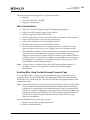
Emulex® Drivers
Version 10.2
for Windows
User Manual
P010077-01A Rev. A
Emulex Connects™ Servers, Storage and People
2
Copyright © 2003-2014 Emulex. All rights reserved worldwide. No part of this document may be reproduced by any
means or translated to any electronic medium without the prior written consent of Emulex.
Information furnished by Emulex is believed to be accurate and reliable. However, no responsibility is assumed by
Emulex for its use; or for any infringements of patents or other rights of third parties which may result from its use. No
license is granted by implication or otherwise under any patent, copyright or related rights of Emulex.
Emulex, the Emulex logo, AutoPilot Installer, AutoPilot Manager, BlockGuard, Connectivity Continuum,
Convergenomics, Emulex Connect, Emulex Secure, EZPilot, FibreSpy, HBAnyware, InSpeed, LightPulse, MultiPulse,
OneCommand, OneConnect, One Network. One Company., SBOD, SLI, and VEngine are trademarks of Emulex. All
other brand or product names referenced herein are trademarks or registered trademarks of their respective
companies or organizations.
Emulex provides this manual "as is" without any warranty of any kind, either expressed or implied, including but not
limited to the implied warranties of merchantability or fitness for a particular purpose. Emulex may make
improvements and changes to the product described in this manual at any time and without any notice. Emulex
assumes no responsibility for its use, nor for any infringements of patents or other rights of third parties that may
result. Periodic changes are made to information contained herein; although these changes will be incorporated into
new editions of this manual, Emulex disclaims any undertaking to give notice of such changes.
Emulex, 3333 Susan Street
Costa Mesa, CA 92626
Note: References to OCe11100 series products also apply to OCe11100R series products.
Emulex Drivers for Windows User Manual
P010077-01A Rev. A
Table of Contents
Table of Contents
List of Figures ......................................................................................9
List of Tables ..................................................................................... 10
1. Introduction ................................................................................... 12
Driver Information .................................................................................. 12
Compatibility .....................................................................................12
Operating System Requirements ..............................................................13
Abbreviations ........................................................................................ 13
2. Installation..................................................................................... 18
Driver Installation Options ........................................................................ 18
OneInstall Installer ..............................................................................18
Loading the OneInstall Package ................................................................... 19
Driver Kit Installer ...............................................................................19
Loading the Driver Kit...........................................................................19
AutoPilot Installer ................................................................................... 20
Starting Installers from a Command Prompt or Script .....................................21
Running a Software Installation Interactively ...............................................21
Option 1: Automatically Run the AutoPilot Installer ........................................... 22
Option 2: Run the AutoPilot Installer Separately ............................................... 22
Hardware-First Installation or Driver Update................................................23
Software-First Installation......................................................................24
Text-Only Driver Installation...................................................................... 24
Unattended Driver Installation ................................................................24
Option 1: Install the Driver Silently ............................................................... 25
Option 2: Run the Driver Kit Installer Separately ............................................... 25
Installation Failure ..............................................................................26
Manually Installing or Updating the Emulex Protocol Drivers .............................. 26
Installing the Emulex PLUS (ElxPlus) Driver for the First Time ...........................26
Updating the Emulex PLUS (ElxPlus) Driver..................................................27
Installing or Updating the FC/FCoE Storport Miniport Driver .............................27
Installing or Updating the iSCSI Driver........................................................28
Installing or Updating the NIC Driver .........................................................29
Windows Server 2008................................................................................ 29
Windows Server 2012................................................................................ 30
Removing Emulex Driver Kits and Drivers...................................................... 30
Uninstalling Emulex Driver Kits ................................................................30
Emulex Drivers for Windows User Manual
P010077-01A Rev. A
3
Table of Contents
Windows Server 2008................................................................................ 30
Windows Server 2012................................................................................ 31
Uninstalling the Emulex Drivers ...............................................................32
Windows Server 2008................................................................................ 32
Windows Server 2012................................................................................ 33
3. Configuration ................................................................................. 34
FC/FCoE Driver Configuration .................................................................... 34
Configuring FC Driver Parameters.............................................................34
Server Performance with FC Drivers ..........................................................42
I/O Coalescing ........................................................................................ 42
Performance Testing ................................................................................ 43
NIC Driver Configuration ........................................................................... 44
Configuring NIC Driver Options ................................................................44
Advisory: PowerShell Behavior..................................................................... 44
Considerations for Using UMC and NIC............................................................ 45
Configuring Windows Server NIC Driver Parameters........................................62
Modifying Advanced Properties .................................................................... 62
Statistics Property Page ............................................................................ 64
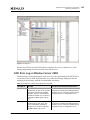
Using OCCFG for Windows NIC Driver Options...............................................68
Displaying OCCFG Help.............................................................................. 68
Selecting an Adapter ................................................................................ 70
Configuring Device Parameters .................................................................... 70
Viewing Device Parameters ........................................................................ 71
Resetting All Parameters ........................................................................... 71
Displaying All Parameters .......................................................................... 72
Using Interactive Mode.............................................................................. 74
Parameter Help ...................................................................................... 75
Using SR-IOV with Emulex Devices ............................................................75
Advisory ............................................................................................... 75
Server BIOS Configuration .......................................................................... 76
Emulex PXESelect Configuration for SR-IOV ..................................................... 76
SR-IOV Server Validation............................................................................ 77
Verifying the Driver Version........................................................................ 78
Enabling SR-IOV in the Emulex Device............................................................ 79
Hyper-V................................................................................................ 80
Verifying SR-IOV...................................................................................... 81
Configuring NVGRE for the OCe14000-series Adapters.....................................83
Setup................................................................................................... 83
Configuration ......................................................................................... 83
Configuring RoCE for the OCe14000-Series Adapters.......................................89
Emulex Drivers for Windows User Manual
P010077-01A Rev. A
4
Table of Contents
Enabling the RoCE Profile on the Client-Side.................................................... 89
Confirming That the RoCE Profile Is Enabled .................................................... 90
Using SMB Direct with NetworkDirect............................................................. 91
Mapping the RoCE-Enabled Client to the Server-Side Storage ................................ 92
SMB Multichannel .................................................................................... 92
SMB Direct Resource Usage......................................................................... 94
QoS Concepts Related to RoCE .................................................................... 96
Configuring QoS for RoCE ........................................................................... 97
Performance Considerations ....................................................................... 98
Configuring Multichannel .......................................................................98
NPar Configuration (Dell Only).................................................................99
Adapter Configuration .............................................................................. 99
NPar Partition Support .............................................................................. 99
NPar Considerations ............................................................................... 100
Enabling NPar Using the Multichannel Property Page ........................................ 100
Using NParEP ....................................................................................... 104
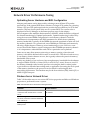
Network Driver Performance Tuning........................................................ 107
Optimizing Server Hardware and BIOS Configuration ........................................ 107
Windows Server Network Driver ................................................................. 107
NUMA Considerations for Windows Server 2012 R2 ........................................... 110
Checksum Offloading and Large Send Offloading (LSO)...................................... 111
Receive Side Scaling (RSS) for Non-Offloaded IP/TCP Network Traffic ................... 111
TCP Offloading (TOE).............................................................................. 112
Receive Window Auto Tuning and Compound TCP............................................ 115
Interrupt Coalescing ............................................................................... 115
CPU Binding Considerations ...................................................................... 116
Single TCP Connection Performance Settings ................................................. 116
iSCSI Driver Configuration ........................................................................117
Configuring iSCSI Driver Options............................................................. 117
Interrupt Moderation Policy Settings ....................................................... 119
Creating Non-Bootable Targets .............................................................. 119
Using the Microsoft iSCSI Initiator Service ..................................................... 119
Logging into a Target Using the Microsoft Software Initiator ............................... 120
Windows Multipath I/O Support ............................................................. 120
Multipath Support.................................................................................. 120
Logging into Targets for Multipath Support.................................................... 121
Maximum Transmission Unit (MTU) for iSCSI Connections ............................... 122
iSCSI Error Handling ........................................................................... 122
Configuring LDTO and ETO on the Windows Server........................................... 123
Error Handling Under MultiPath (MPIO) and Cluster Configurations ....................... 123
Emulex Drivers for Windows User Manual
P010077-01A Rev. A
5
Table of Contents
4. Troubleshooting ............................................................................ 124
General Troubleshooting .........................................................................124
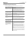
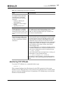
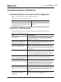
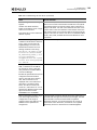
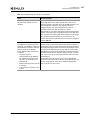
Troubleshooting the FC/FCoE Driver ...........................................................124
Troubleshooting the Cisco Nexus Switch Configuration.................................. 124
Event Trace Messages ......................................................................... 125
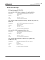
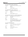
ELS Log Messages (0100–0130) ................................................................... 125
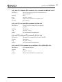
Discovery Log Messages (0202–0262) ............................................................ 128
Mailbox Log Messages (0310–0326) .............................................................. 131
INIT Log Messages (0400–0463)................................................................... 132
FCP Log Messages (0701–0749) ................................................................... 134
Link Log Messages (1302–1306) .................................................................. 137
Tag Messages (1400–1401) ........................................................................ 138
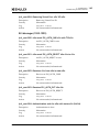
NPIV Messages (1800–1899) ....................................................................... 139
ELS Messages (1900–1999) ........................................................................ 140
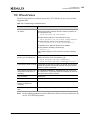
Troubleshooting the NIC Drivers ................................................................142
Monitoring TCP Offloads ...................................................................... 143
TCP Offload Failure............................................................................ 144
Troubleshooting the iSCSI Driver................................................................145
Troubleshooting the Cisco Nexus Switch Configuration.................................. 145
iSCSI Driver Troubleshooting ................................................................. 145
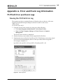
Appendix A. Error and Event Log Information........................................... 148
FC/FCoE Error and Event Logs ...................................................................148
Viewing the FC/FCoE Error Log .............................................................. 148
Severity Scheme ................................................................................... 149
Related Driver Parameter: LogError ............................................................ 149
Format of an Error Log Entry..................................................................... 149
Error Codes Tables................................................................................. 150
Viewing the FC/FCoE Event Log ............................................................. 155
Event Log Interpretation.......................................................................... 155
Additional Event Log Information ............................................................... 155
ASC/ASCQ ........................................................................................... 157
Additional Notes on Selected Error Codes ..................................................... 158
NIC Error and Event Logs .........................................................................159
Viewing the NIC Error Log .................................................................... 159
RoCE Event Log................................................................................. 159
NIC Event Log................................................................................... 160
iSCSI Error and Event Log.........................................................................164
Viewing the iSCSI Error and Event Log on Windows Server 2008 ....................... 164
iSCSI Error Log on Windows Server 2008 ................................................... 165
Emulex Drivers for Windows User Manual
P010077-01A Rev. A
6
Table of Contents
Viewing the iSCSI Error Log on Windows 7, Windows 8, Windows 8.1,
Windows Server 2008 R2, Windows Server 2012, and
Window Server 2012 R2 ....................................................................... 168
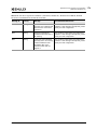
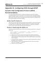
Appendix B. Configuring iSCSI through DHCP ............................................ 177
Dynamic Host Configuration Protocol (DHCP) Recommendations ........................177
Vendor-Specific Option 43.................................................................... 177
Format of Vendor-Specific Option 43 ....................................................... 177
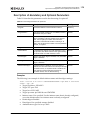
Description of Mandatory and Optional Parameters...................................... 178
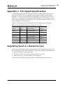
Appendix C. Port Speed Specifications ................................................... 180
Negotiating Speed on a Mezzanine Card.......................................................180
Appendix D. AutoPilot Installer Command Line and
Configuration File Parameters.............................................. 181
AParg Driver Kit Parameter and Appending to the APInstall.exe File ...................181
AutoPilot Installer Syntax.........................................................................182
Path Specifiers ................................................................................. 182
Configuration File Location .................................................................. 183
Software Configuration Parameters......................................................... 183
DiagEnable (Running Diagnostics) ............................................................... 183
ForceDriverTypeChange (Forcing a Driver Type Change) .................................... 183
ForceDriverUpdate (Forcing a Driver Version Update) ....................................... 183
ForceRegUpdate (Forcing an Update of an Existing Driver Parameter Value)............ 184
LocalDriverLocation (Specifying Location to Search for Drivers) ........................... 184
NoSoftwareFirstInstalls (Prohibiting Software First Installations).......................... 184
ReportLocation (Setting Up an Installation Report Title and Location) ................... 185
SilentInstallEnable (Enabling Unattended Installation) ...................................... 185
SilentRebootEnable (Enabling Silent Reboot) ................................................. 185
InstallWithoutQFE (Enabling Installation if a QFE Check Fails) ............................. 185
AutoPilot Configuration File .....................................................................186
Using the Windows Environment Variable (%ProgramFiles%)............................ 186
Configuration Identification [AUTOPILOT.ID].............................................. 186
Software Configuration [AUTOPILOT.CONFIG] ............................................ 187
Configuration Prompts/Vendor-Specific Questions [STORPORT.CONFIGURATION] .. 187
QFE Checks [STORPORT.QFES] ............................................................... 188
Setting Up FC Driver Parameters [STORPORT.PARAMS].................................. 189
Setting Up System Parameters [SYSTEM.PARAMS] ........................................ 189
AutoPilot Installer Exit Codes....................................................................190
AutoPilot Installer Installation Reports ........................................................191
Command Script Example ........................................................................191
Emulex Drivers for Windows User Manual
P010077-01A Rev. A
7
Table of Contents
Appendix E. RoCE Switch Support.......................................................... 193
Overview .............................................................................................193
DCBX-Enabled Switch Connection PFC Mode .................................................193
Switch Configuration for PFC Priority 5 .................................................... 193
Host—Client Configuration ................................................................... 194
DCBX-Disabled Switch Connection (Generic Pause Mode) ................................... 194
Examples for Cisco Switch........................................................................ 194
Verifying Switch Configuration in OneCommand Manager................................... 197
Emulex Drivers for Windows User Manual
P010077-01A Rev. A
8
List of Figures
List of Figures
Figure 2-1
Figure 3-1
Figure 3-2
Figure 3-3
Figure 3-4
Figure 3-5
Figure 3-6
Figure 3-7
Figure 3-8
Figure 3-9
Figure 3-10
Figure 3-11
Figure 3-12
Figure
Figure
Figure
Figure
Figure
Figure
Figure
Figure
3-13
3-14
3-15
3-16
3-17
3-18
3-19
3-20
Figure 3-21
Figure A-1
Figure A-2
AutoPilot Installer Warning (Software-First Installation) ...........................24
Partial View of Windows Device Manager .............................................63
NIC Advanced Properties in Windows Server 2008 ...................................64
NIC Statistics Properties in Windows Server 2008....................................65
Device Manager for Windows Server 2012.............................................78
Emulex NIC Driver Properties Page .....................................................79
Emulex NIC Advanced Properties Page ................................................80
Emulex NIC Statistics Properties page .................................................82
Advanced Property Configuration - RoCE-Enabled ...................................90
Get-NetAdapterRDMA - RoCE-Enabled .................................................90
Get-NetOffloadGlobal - RoCE-Enabled.................................................91
Active Network Connections and Listeners ...........................................91
SMB Share - Two RDMA Connections Per
RDMA-Enabled Network Interface ......................................................92
Get-NetAdapterStatistics ................................................................92
Two SMB Direct Connections Per Interface ...........................................93
Multichannel Constraint..................................................................94
Resource Counts on a 1-Port 10Gb or 40Gb OCe14000-Series Adapter ...........95
Resource Counts on a 2-Port 10Gb OCe14000-Series Adapter......................95
Resource Counts on a 4-Port 10Gb OCe14000-Series Adapter......................95
The Multichannel Property Page with NPar Disabled .............................. 101
The Multichannel Property Page with NPar Enabled and
NParEP Disabled ......................................................................... 103
The Multichannel Property Page with NPar Enabled and
NParEP Enabled.......................................................................... 105
Event Properties......................................................................... 148
iSCSI Error ................................................................................ 165
Emulex Drivers for Windows User Manual
P010077-01A Rev. A
9
List of Tables
List of Tables
Table 3-1
Table 3-2
Table 3-3
Table 3-4
Table 3-5
Table 3-6
Table 3-7
Table 3-8
Table 3-9
Table 3-10
Table 3-11
Table 3-12
Table 3-13
Table 3-14
Table 4-1
Table 4-2
Table 4-3
Table 4-4
Table 4-5
Table 4-6
Table A-1
Table A-2
Table A-3
Table A-4
Table A-5
Table A-6
Table A-7
Table A-8
Table A-9
Table A-10
Table A-11
Table A-12
Table A-13
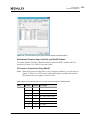
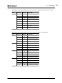
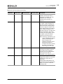
Storport Miniport Driver Parameters ...................................................35
Recommended Settings for I/O Coalescing ...........................................42
Windows Server 2008, Windows Server 2008 R2,
Windows Server 2012, and Windows Server 2012 R2
NIC Driver Options ........................................................................47
NIC Driver Properties Statistics .........................................................65
SMB Direct Active Connections (Client Mode) Per Port for
OCe14000-Series Adapters ...............................................................95
PCI Function Representation for a Two-Port Adapter ............................. 102
PCI Function Representation for a Four-Port Adapter............................. 102
PCI Function Representation for a 2-Port 16-Function Adapter—
NParEP Enabled.......................................................................... 105
PCI Function Representation for a 4-Port 16 Function Adapter—
NParEP Enabled.......................................................................... 106
Windows Server Performance Tuning Situations ................................... 107
Statistics and Fine Tuning ............................................................. 108
iSCSI Driver Options..................................................................... 117
im_policy Settings....................................................................... 119
LDTO and ETO Information on the Windows Server................................ 123
General Troubleshooting............................................................... 124
Cisco Nexus Switch Situations ......................................................... 124
Troubleshooting the NIC Drivers ...................................................... 142
Troubleshooting TCP Offload Failures ............................................... 144
Cisco Nexus Switch Situations for iSCSI .............................................. 145
Troubleshooting the iSCSI Driver ..................................................... 145
Severe Errors............................................................................. 150
Malfunction Errors ...................................................................... 152
Command Errors......................................................................... 153
Event Indications ........................................................................ 154
ELS/FCP Command Error Status Codes............................................... 155
CT Command Response Codes......................................................... 155
FC-CT Reject Reason Codes ........................................................... 156
ELS Command Codes.................................................................... 156
SCSI Status Codes ....................................................................... 156
Local Reject Status Codes ............................................................. 157
SRB Status Codes ........................................................................ 157
RoCE Event Log Entries................................................................. 159
NIC Event Log Entries................................................................... 160
Emulex Drivers for Windows User Manual
P010077-01A Rev. A
10
List of Tables
Table A-14
Table A-15
Table B-1
Table C-1
Table D-1
iSCSI Error Log Entries on Windows Server 2008 ................................... 165
iSCSI Error Log Entries on Windows 7, Windows 8, Windows 8.1,
Windows Server 2008 R2, Windows Server 2012, and
Windows Server 2012 R2 ............................................................... 168
Data String Parameters for Option 43................................................ 178
Negotiated Speed Specification per Adapter Port Connection................... 180
Unattended Installation Error Codes ................................................. 190
Emulex Drivers for Windows User Manual
P010077-01A Rev. A
11
1. Introduction
Driver Information
1. Introduction
Driver Information
This product supports the Emulex® OneConnect™ family of universal converged
network adapters (UCNAs) and the Emulex LightPulse® family of host bus adapters
(HBAs) and converged fabric adapters (CFAs).
The Windows drivers support the following protocols:
Fibre Channel (FC)
FC over Ethernet (FCoE)
Ethernet (NIC), which includes the TCP Offload Engine (TOE)
Internet Small Computer System Interface (iSCSI)
RDMA over Converged Internet (RoCE) for the OCe14000-series adapters
Note: TOE is not supported on OCe14000-series and LPe16202 adapters.
This document explains how to install the Windows drivers on your system and
configure the drivers’ capabilities based on the supported networking protocols:
FC and FCoE
Configuring the FC/FCoE driver parameters
Improving server performance with FC/FCoE drivers
Ethernet and TOE
Configuring NIC driver options
SR-IOV
Configuring NVGRE
Configuring RoCE supporting SMB Direct
Configuring Multichannel
Configuring NIC partitioning (NPAR) for Dell only
Tuning network driver performance
iSCSI
Configuring iSCSI driver options
Creating non-bootable targets
Configuring Multipath I/O
A NIC teaming package driver and manager are also available as a separate download.
The user manual, OneCommand NIC Teaming and VLAN Manager User Manual, is
available for download as well. See the Emulex website for more information.
Compatibility
For a list of adapters that are compatible with this driver, see the driver's Downloads
page on the Emulex website. For compatible firmware versions, see the Downloads
page for the specific adapter.
Emulex Drivers for Windows User Manual
P010077-01A Rev. A
12
1. Introduction
Abbreviations
Operating System Requirements
One of the following operating systems must be installed on an x64 server:
Windows Server 2008, Windows Server 2008 R2, Windows Server 2012, and
Windows Server 2012 R2: x64 versions, Enterprise and Server Core installation
Note: The Microsoft patch KB2846340 must be installed on your system in
order for the NIC installation to be successful. If the patch is not installed
on your system, the installation stops and asks you to install it. This
patch from Microsoft's Knowledge Base (kb), is available for Windows
Server 2012, Windows Server 2008 R2, and Windows Server 2008 SP2 on
the Microsoft website.
Windows 7 Ultimate, Enterprise, or Professional edition (x64 only; supported
on only OneConnect OCe11100-series Universal Converged Network Adapters
(UCNAs))
Windows 8 and Window 8.1 x64 base version, Pro and Enterprise (x64 only;
supported on only OCe11100-series UCNAs)
Notes:
Windows 7 x64, Windows 8 x64, and Windows 8.1 x64 drivers are
Emulex-signed. You must accept the Emulex certificate to install these kits.
Support is provided by Emulex, but not by Microsoft.
Check the Emulex website for required updates to the Windows operating
system or the Emulex drivers.
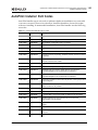
Abbreviations
ACC
accept
ACK
acknowledgement
ADISC
discover address
AL_PA
arbitrated loop physical address
API
application programming interface
ARI
Alternative Routing-ID Interpretation
ARM
Advanced RISC Machine
ASC
additional sense code
ASCQ
additional sense code qualifier
BIOS
basic input-output system
CFA
converged fabric adapter
CHAP
Challenge Handshake Authentication Protocol
CLI
command line interface
CNT
count
CPU
central processing unit
Emulex Drivers for Windows User Manual
P010077-01A Rev. A
13
1. Introduction
Abbreviations
CRC
cyclic redundancy check
CT
command transport
CTCP
compound TCP
DAS
direct-attached storage
DCB
Data Center Bridging
DCBx
Data Center Bridging Exchange Protocol
DPC
deferred procedure call
DHCP
Dynamic Host Configuration Protocol
DID
destination ID
DIMM
dual in-line memory module
DISC
discover
DISC CNT
discovery node count
DMA
direct memory access
DNS
domain name server
DSM
device specific module
ELS
extended link service
ETO
extended time out
ETS
enhanced transmission selection
FAN
file area network
FC
Fibre Channel
FC-AL
Fibre Channel arbitrated loop
FCoE
Fibre Channel over Ethernet
FCP
Fibre Channel Protocol
FDISC
Discover F_Port Service Params
FDMI
Fabric-Device Management Interface
FLOGI
fabric login
FW
firmware
Gen 2 or Gen2
Generation 2 PCIe
GET_FT
get port identifiers
GSI
General Service Interface
GUI
graphical user interface
HBA
host bus adapter
hex
hexadecimal
ICMP
Internet Control Message Protocol
IEEE
Institution of Electrical and Electronics Engineers
IET
iSCSI Enterprise Target
Int
interrupts
Emulex Drivers for Windows User Manual
P010077-01A Rev. A
14
1. Introduction
Abbreviations
I/O
Input/Output
IOCTL
Input/Output control
iocb
input/output control block
IOMMU
input/output memory management unit
IP
internet protocol
IPL
initial program load
IP NAT
IP network address translation
IPSec
IP Security protocol
IPv4
Internet Protocol version 4
IPv6
Internet Protocol version 6
iSCSI
internet Small Computer System Interface
iSNS
internet Storage Name Server
IQN
iSCSI Qualified Name
KB
kilobyte or Knowledge Base
LACP
Link Aggregation Control Protocol
LAN
local area network
LBFO
load balancing and failover
LDTO
link down time out
LOGO
N_Port Logout
LRO
large receive offload
LSO
large send offload
LS_RJT
link service reject
LUN
logical unit number
MAC
media access control
MMC
Microsoft Management Console
MPIO
multipath input/output
MSI
message signaled interrupt
MSS
maximum segment size
MTU
maximum transmission unit
N/A
not applicable
NAS
network-attached storage
NAT
network address translation
NDIS
Network Driver Interface Specification
NIC
network interface card (or controller)
NPar
NIC partition
NPIV
N_Port ID virtualization
NTFS
New Technology File System
Emulex Drivers for Windows User Manual
P010077-01A Rev. A
15
1. Introduction
Abbreviations
NUMA
non-uniform memory access
NVGRE
network virtualization generic routing encapsulation
OCCFG
OneConnect config
OS
operating system
PCI
peripheral controller interface
PCIe
peripheral controller interface express
PDISC
discover N_Port service parameter
PE
pre-installation environment
PF
PCI function
PFC
process flow control
PHY
physical layer
PLOGI
Port login
POST
power-on self-test
PRLI
process login
PRLO
process logout
PT-PT
point to point fabric topology
PXE
Pre-boot Execution Environment
QFE
Quick Fix Engineering
QoS
quality of service
QP
queue pairs
RAID
redundant array of independent disks
RCMD
Remote Command Service
RDMA
remote direct memory access
Recv
received
RNIC
RDMA network interface
RoCE
RDMA over converged Ethernet
ROM
read-only memory
RPI
remote port indicator
RSC
receive segment coalescing
RSCN
Register State Change Notify
RSS
receive side scaling
Rx
receive
SACK
selective acknowledgement
SAN
storage area network
SCSI
Small Computer System Interface
SFP
small form factor pluggable
SLI
service level interface
Emulex Drivers for Windows User Manual
P010077-01A Rev. A
16
1. Introduction
Abbreviations
SMB
server message block
SRB
SCSI Request Block
SR-IOV
Single Root I/O Virtualization
SSH
Secure Shell network protocol
TCP
Transmission Control Protocol
TCP PSH
TCP “push” flag
TMF
task management function
TMO
timed out
TOE
TCP Offload Engine
TSO
TCP segmentation offload
Tx
transmit
UCNA
Universal Converged Network Adapter
UDP
User Datagram Protocol
UE
unrecoverable error
UI
user interface
UEFI BIOS
Unified Extensible Firmware Interface BIOS
ULP
Upper Layer Protocol
UMC
Universal Multichannel
UNC
universal naming convention
VF
virtual function
VLAN
virtual local area network
VLANID
virtual local area network id
VM
virtual machine
VMQ
virtual machine queue
VPN
virtual private network
vPort
virtual port
WAIK
Windows Automated Installation Kit
WMI
Window Management Instrumentation
WWN
world wide name
WWNN
world wide node name
WWPN
world wide port name
XRI
exchange resource indicator
Emulex Drivers for Windows User Manual
P010077-01A Rev. A
17
2. Installation
Driver Installation Options
2. Installation
Driver Installation Options
There are two ways that you can install the Windows drivers:
OneInstall Installer contains all the Emulex Windows drivers (Emulex Storport
Miniport and NDIS Miniport drivers) and the OneCommand Manager
application in a single download package.
Driver kits and AutoPilot Installer provide installation options ranging from
simple installations with a few mouse clicks to unattended installations that use
predefined script files and text-only installations.
Notes:
If you are installing the NIC driver kit as an update to the Windows Server 2012
driver, some parameter defaults are different from the inbox driver. Emulex
recommends that, after you install the Emulex out-of-box driver, you select
“reset to default” on the Advanced tab of Device Manager property page. This
returns all adapter and driver settings to the default values listed in this
manual.
Low performance can result when the Emulex NIC driver is installed on a
system meeting the following conditions before installing Microsoft KB2846837:
A Windows 8, Windows 8.1, or Windows Server 2012 computer with
multi-core processors is in use.
Three or more Ethernet ports are installed on the computer.
Receive Side Scaling (RSS) is enabled and sets the RSS profile to use the
“Closest” parameter for the Ethernet adapters.
If these conditions exist, install KB2846837 before installing the Emulex NIC
driver.
OneInstall Installer
Note: The OneInstall Installer does not allow you to perform pre-installation tasks,
unattended installations, or text-only installations. For these tasks, use the
driver kits.
The OneInstall package is a self-extracting executable file that installs the following
software on your system:
All compatible protocol drivers:
FC
FCoE
iSCSI
NIC
NIC+RoCE
Emulex Drivers for Windows User Manual
P010077-01A Rev. A
18
2. Installation
Driver Installation Options
ElxPlus driver (supports the OneCommand Manager application, persistent
binding, and LUN mapping and masking)
OneCommand Manager application for Emulex adapters
Note: The Enterprise kit for the OneCommand Manager application does not
operate locally on Windows Server Core. You must install the
OneCommand Manager Core Kit (command-line interface only) to the
Windows Server Core.
Loading the OneInstall Package
To install the drivers using the OneInstall package:
1.
2.
3.
4.
5.
Download the OneInstall package from the Emulex website.
Navigate to the OneInstall package in Windows Explorer.
Double-click the OneInstall package. The Welcome screen appears.
Click Next. The Installation options screen appears.
Select the drivers and application that you want to install and click Next.
A progress screen appears while the OneInstall installer loads the selected drivers
and applications. When the drivers and application software are loaded, an
Installation completed screen appears.
6. Click Finish.
Driver Kit Installer
Each driver kit contains and loads all the Windows drivers for a specific protocol, and
includes ElxPlus.
FC driver package (elxdrvr-fc-<version>.exe)
FCoE driver package (elxdrvr-fcoe-<version>.exe)
iSCSI driver package (elxdrvr-iscsi-<version>.exe)
NIC+RoCE driver package (elxdrvr-nic-<version>.exe)
Note: Updating the NIC protocol driver may temporarily disrupt operation of any
NIC teams configured on the system.
Loading the Driver Kit
The driver kit copies the selected Emulex drivers and applications onto your computer.
Note: This procedure does not install drivers, and no driver changes are made until
you run the AutoPilot Installer.
To load the driver kit:
1.
2.
3.
4.
Download the driver kit from the Emulex website to your system.
Double-click to run the driver kit. The Emulex Kit Welcome page opens.
Click Next. The Installation Options page opens.
Select one or both of the following options:
Emulex Drivers for Windows User Manual
P010077-01A Rev. A
19
2. Installation
AutoPilot Installer
Perform Installation of Software - copies the driver kit for your operating
system to your computer.
Unpack All Drivers - extracts all drivers to the current user’s documents folder.
Select this option to perform boot from SAN installations.
The Operation in progress page shows the kit file loading progress. When the kit
files are loaded, the Installation completed page opens.
5. If you wish to continue with the installation, ensure that Start AutoPilot Installer is
checked. Click Next.
AutoPilot Installer
AutoPilot Installer runs after the driver kit is loaded and the OneCommand Manager
application is installed. AutoPilot Installer can install drivers:
Immediately after the driver kit has been loaded
At a later time using an interactive installation
Through an unattended installation
AutoPilot Installer provides:
Command line functionality – Initiates an installation from a command prompt
or script. Configuration settings can be specified in the command line.
Compatibility verification – Verifies that the driver to be installed is compatible
with the operating system and platform.
Driver installation and update – Installs and updates drivers.
Multiple adapter installation capability – Installs drivers on multiple adapters,
alleviating the need to manually install the same driver on all adapters in the
system.
Driver diagnostics – Determines whether the driver is operating properly.
Silent installation mode – Suppresses all screen output (necessary for
unattended installation).
Note: AutoPilot Installer does not allow you to install the driver if the minimum
Windows service pack or Microsoft Storport driver update is not installed.
You can install a driver by any of the following methods:
Note: These methods are not mutually exclusive.
Hardware-first installation – At least one Emulex adapter must be installed
before you can install the Emulex drivers and utilities.
Software-first installation – You can install drivers and utilities using
AutoPilot Installer prior to the installation of any adapters. You do not need to
specify the adapter models to be installed later. The appropriate drivers and
utilities automatically load when you install the adapters.
Utility-only installation – If the drivers in the driver kit share the same version
with those already installed on the system, you can reinstall or update the
previously installed utility without reinstalling the drivers.
Emulex Drivers for Windows User Manual
P010077-01A Rev. A
20
2. Installation
AutoPilot Installer
Text-only installation – Text-based installation mode is used automatically
when AutoPilot Installer is run on a Server Core system.
Network installation – You can place the driver kit installers on a shared
network drive and install them across your LAN. Network-based installation is
often used in conjunction with unattended installation and scripting. This
allows you to configure and install the same driver version on all the hosts in a
SAN.
Unattended installation – You can run the driver kit and AutoPilot Installer
with no user interaction from a command line or script. Unattended installation
works for both hardware-first and software-first installations and all driver kits.
An unattended installation operates in silent mode (also referred to as quiet
mode) and creates an extensive report file with installation status.
Note: Complete driver and utilities documentation may be downloaded from the
Emulex website (www.emulex.com). Click Downloads at the top of the web
page and navigate by clicking the appropriate links.
Starting Installers from a Command Prompt or Script
When a driver kit or AutoPilot Installer is run from a command prompt or command
script (batch file), the Windows command processor does not wait for the installer to
run to completion. As a result, you cannot check the exit code of the installer before the
next command is executed. Emulex recommends that for command line invocation,
always use the “start” command with the “/wait” option. This causes the command
processor to wait for the installer to finish before it continues.
For more information on command line installation and configuration parameters, see
appendix D., “AutoPilot Installer Command Line and Configuration File Parameters,”
on page 181.
Running a Software Installation Interactively
There are two options when performing an installation interactively. These options
assume you have already downloaded the driver kit from the Emulex website.
Option 1 allows you to automatically run the AutoPilot Installer, which
completes the driver kit loading and AutoPilot installation with a few mouse
clicks.
Option 2 allows you to run the AutoPilot Installer separately. This option is
recommended when:
Changing installation settings for a limited number of systems.
Familiarizing yourself with AutoPilot Installer configuration options.
Emulex Drivers for Windows User Manual
P010077-01A Rev. A
21
2. Installation
AutoPilot Installer
Option 1: Automatically Run the AutoPilot Installer
Use this option unless you have specific configuration needs.
1. Double-click the driver kit or run it from a command line. See appendix D.,
“AutoPilot Installer Command Line and Configuration File Parameters,” on
page 181 for information on the command line options. The command line
parameter APargs allows you to specify arguments that are automatically passed to
the AutoPilot Installer command. A Welcome page is displayed with driver kit
version information and Emulex contact information.
2. Click Next to proceed to the Installation Options page.
For each installation option, the default installation location for that option is
displayed. Browse to a different location, if desired.
3. Click Install to continue the installation.
The Progress dialog box is displayed. After all tasks are completed, the Finish
dialog box is displayed. The Start AutoPilot Installer box is automatically selected.
4. Click Finish. AutoPilot Installer runs automatically and completes one of the
following installations:
Hardware-First Installation or Driver and Utility Update (page 23).
Software-First Installation (page 24).
Option 2: Run the AutoPilot Installer Separately
To access these options, run AutoPilot Installer after the driver kit loading has been
completed. This allows you to change the configuration options supplied to the
AutoPilot Installer (see below).
1. Perform steps 1 through 3 for “Option 1: Automatically Run the AutoPilot
Installer”.
2. Clear the Run AutoPilot Installer check box on the Finish dialog box.
3. Click Finish. The driver kit installer exits.
After the driver kit loading is complete, change the configuration in one of two ways:
Change the configuration file. See “Software Configuration Parameters” on
page 183 for details.
Supply parameters on the command line. See appendix D., “AutoPilot Installer
Command Line and Configuration File Parameters,” on page 181 for details.
Once you have finished this step, you can run AutoPilot Installer at a later time, using
either of the following methods:
Note:
If you are supplying options using the command line, you must run AutoPilot
Installer from the command line.
Select Programs>Emulex>AutoPilot Installer in the Start menu.
Run AutoPilot Installer from the command line. Type
C:\Program Files\Emulex\AutoPilot Installer\<driver type>\APInstall.exe
Emulex Drivers for Windows User Manual
P010077-01A Rev. A
22
2. Installation
AutoPilot Installer
Note: The location of APInstaller.exe may differ on your system, depending on
your system's Program Files location. You may also specify a different
location when you install the driver package.
Hardware-First Installation or Driver Update
The driver kit must be downloaded from the Emulex website and loaded.
Notes:
Updating the NIC protocol driver may temporarily disrupt operation of any
NIC teams configured on the system.
To update the Emulex protocol drivers, begin the procedure at step 2.
To perform a hardware-first installation:
1. Install a new Emulex adapter and power-on the system. If the Windows Found
New Hardware wizard is displayed, click Cancel to exit. AutoPilot Installer
performs this function.
Note: If there are multiple adapters in the system, the Windows Found New
Hardware wizard appears multiple times. Click Cancel to exit the wizard
each time it appears.
2. Run AutoPilot Installer using one of the two options listed in “Running a Software
Installation Interactively” on page 21.
3. When the AutoPilot Installer Welcome page appears, select an adapter in the list
and click Next. The installation continues.
Consider the following:
If you are updating the driver, the existing port settings are used, unless
otherwise specified in the AutoPilot configuration file. These settings are
pre-selected but can be changed. Set or change settings, then click Next.
If you are initially installing a vendor-specific version of the Emulex driver
installation program, a Driver Configuration page may be displayed. This page
includes one or more windows with questions that you must answer before
continuing the installation process. In this case, answer each question and click
Next on each window to continue.
4. Click Next. The installation is completed automatically. A dialog box is displayed if
Windows requires a reboot. Once the installation is successful, the Finish dialog box
appears.
5. View or print a report, if desired.
View Installation Report – The installation report is a text file with current
Emulex adapter inventory, configuration information, and task results.
Print Installation Report – The Windows print dialog box is displayed to select
options for printing the installation report.
6. Click Finish to exit AutoPilot Installer. If the system must be rebooted, you are
prompted to do so as indicated in step 4; you must reboot before using the drivers
or utilities.
Emulex Drivers for Windows User Manual
P010077-01A Rev. A
23
2. Installation
Text-Only Driver Installation
Software-First Installation
The driver kit must be downloaded from the Emulex website and loaded. Either the full
or core driver package may be installed; only one can be installed on a system.
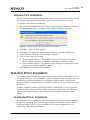
To perform a software-first installation:
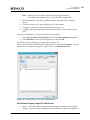
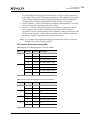
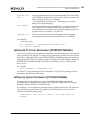
1. Run AutoPilot Installer using one of the two options listed in “Running a Software
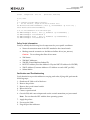
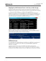
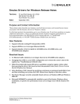
Installation Interactively” on page 21. The warning in Figure 2-1 appears:
Figure 2-1 AutoPilot Installer Warning (Software-First Installation)
2. Click OK. A Welcome page appears.
3. Click Next. The installation automatically progresses. Once the installation is
completed successfully, the Finish dialog box appears.
4. View or print a report, if desired.
View Installation Report – The installation report is a text file with current
Emulex adapter inventory, configuration information, and task results.
Print Installation Report – The Windows print dialog box is displayed to select
options for printing the installation report.
5. Click Finish to exit the AutoPilot Installer.
Text-Only Driver Installation
Text-based installation mode is used automatically when the driver kit installer runs on
a server with the Server Core installation option of Windows Server. During text-based
installations, AutoPilot Installer uses a command prompt window. The driver kit
installer notifies you when the driver is installed and also gives you a chance to stop the
installation.
Whether AutoPilot installer is launched from the command line or run as a program,
Windows always starts AutoPilot Installer as a separate stand-alone task. This means
that AutoPilot Installer has its own command prompt window and cannot access
others.
Unattended Driver Installation
An unattended driver installation, sometimes referred to as a quiet or silent installation,
requires no user input. This is useful for performing an installation remotely from a
command script, or when you want to make sure a custom configuration is not
changed by a user during installation.
Emulex Drivers for Windows User Manual
P010077-01A Rev. A
24
2. Installation
Text-Only Driver Installation
When in unattended installation mode, AutoPilot Installer does the following:
Reads the configuration file
Reads any options that may be specified on the command line, overriding the
configuration file settings as appropriate
Opens the installation report file
Validates the operating system
Discovers adapters and records the adapter inventory in the report file
Verifies mandatory configuration file parameters
Searches for drivers to install based on the LocalDriverLocation setting in the
configuration file
Verifies, if appropriate, that the selected driver is either a different type than the
currently installed driver or a more recent version of the currently installed
driver
Copies the driver parameters from the configuration file into the registry for the
driver's co-installer (FC and FCoE drivers only)
Installs or updates the driver
Rediscovers adapters and records the updated adapter inventory in the report
file
Records the final results and closes the report file
There are two ways to perform an unattended installation:
Install the driver silently.
Run the driver kit installer separately.
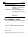
Option 1: Install the Driver Silently
Run the driver kit from a command prompt or script. Specify the “/q” (quiet) command
line option. For example:
elxdrv-fc-fcoe<version>.exe /q
Note: The name of the driver kit depends on the current version identifier. For other
command line options, see “AutoPilot Installer Command Line and
Configuration File Parameters” on page 181.
Option 2: Run the Driver Kit Installer Separately
1. Follow steps 1–3 for “Running a Software Installation Interactively” on page 21.
2. Clear the Run AutoPilot Installer check box on the Finish dialog box.
3. Choose one of the following options:
Run the AutoPilot Installer from a command prompt or script with the silent
option:
APInstall.exe /silent
Edit the AutoPilot Installer configuration file before running AutoPilot Installer.
The configuration file is typically located in:
C:\Program Files\Emulex\AutoPilot Installer\<driver type>\APInstall.cfg
Emulex Drivers for Windows User Manual
P010077-01A Rev. A
25
2. Installation
Manually Installing or Updating the Emulex Protocol Drivers
Uncomment the line that sets “SilentInstallEnable” to “True”. There are other
settings in the same section of the configuration file related to unattended
installations that you may also want to edit. See “Software Configuration
Parameters” on page 183 for more information. After editing the file, you can
run the AutoPilot Installer from the Start menu, a command prompt, or a script.
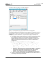
Installation Failure
If the installation fails, the Diagnostics window displays that the adapter failed.
If the adapter fails:
1. Select the adapter to view the reason for the failure. The reason and suggested
corrective action are displayed.
2. Perform the suggested corrective action and run AutoPilot Installer again.
Note: You can run AutoPilot Installer again from the Start menu
(Programs>Emulex>AutoPilot Installer) or you can run APInstall.exe from
a command prompt.
Manually Installing or Updating the Emulex Protocol
Drivers
You can install or update the Emulex protocol drivers and utilities manually without
using AutoPilot Installer.
The Emulex PLUS (ElxPlus) driver supports the OneCommand Manager application,
persistent binding, and LUN mapping and masking.
Note: The ElxPlus driver must be installed before you install the Emulex protocol
drivers.
Installing the Emulex PLUS (ElxPlus) Driver for the First
Time
Note: Only one instance of the ElxPlus driver should be installed, even if you have
multiple adapter ports installed in your system.
To install the ElxPlus driver from the desktop:
1. Run the driver kit installer, but do not run AutoPilot Installer. See “Running a
Software Installation Interactively” on page 21 for instructions.
2. Select Start>Settings>Control Panel>Add Hardware. The Add Hardware Wizard
window appears. Click Next.
3. Select Yes, I have already connected the hardware and click Next.
4. Select Add a new hardware device and click Next.
5. Select Install the hardware that I manually select from a list (Advanced) and click
Next.
Emulex Drivers for Windows User Manual
P010077-01A Rev. A
26
2. Installation
Manually Installing or Updating the Emulex Protocol Drivers
6. Select Show All Devices and click Next.
7. Click Have Disk... and direct the Device Wizard to the location of elxplus.inf. If you
have installed the driver installer kit in the default folder and C:\ is your Windows
system drive, the path is:
C:\Program Files\Emulex\AutoPilot Installer\Drivers\Storport\x64\HBA
8. Click OK.
9. Select Emulex PLUS. Click Next and click Next again to install the driver.
10. Click Finish. The initial ElxPlus driver installation has completed. Continue with
manual installation of the Storport Miniport Driver. See “Installing or Updating the
FC/FCoE Storport Miniport Driver” on page 27 for this procedure.
Updating the Emulex PLUS (ElxPlus) Driver
Note: Only one instance of the ElxPlus driver should be installed, even if you have
multiple adapter ports installed in your system.
To update an existing ElxPlus driver from the desktop:
1. Run the driver kit installer, but do not run AutoPilot Installer. See “Running a
Software Installation Interactively” on page 21 for instructions on how to do this.
2. Select Start>Settings>Control Panel>Administrative Tools>Computer
Management.
3. Click Device Manager (left pane).
4. Click the plus sign (+) next to the Emulex PLUS class (right pane) to show the
ElxPlus driver entry.
5. Right-click the ElxPlus driver entry and select Update Driver... from the menu.
6. Select No, not this time. Click Next on the Welcome to the Hardware Update
Wizard window. Click Next.
7. Select Install from a list or specific location (Advanced) and click Next.
8. Select Don’t Search. I will choose the driver to install.
9. Click Have Disk... and direct the Device Wizard to the location of the driver’s
distribution kit. If you have installed the driver installer kit in the default folder, the
path is:
C:\Program Files\Emulex\AutoPilot Installer\Drivers\Storport\x64
10. Click OK. Select Emulex PLUS.
11. Click Next to install the driver.
12. Click Finish. The ElxPlus driver update is finished. Continue with manual
installation of the Storport Miniport Driver.
Installing or Updating the FC/FCoE Storport Miniport Driver
To update or install the FC/FCoE Storport Miniport driver from the desktop:
1. Select Start>Settings>Control Panel>System.
2. Select the Hardware tab.
3. Click Device Manager.
Emulex Drivers for Windows User Manual
P010077-01A Rev. A
27
2. Installation
Manually Installing or Updating the Emulex Protocol Drivers
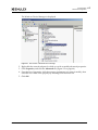
4. Open the SCSI and RAID Controllers item.
5. Double-click the desired Emulex adapter.
Note: The driver affects only the selected adapter. If there are other adapters in the
system, you must repeat this process for each adapter. All dual-channel
adapter models are displayed in Device Manager as two adapters, and each
adapter must be updated.
6. Select the Driver tab.
7. Click Update Driver. The Update Driver wizard starts.
8. Select No, not this time. Click Next on the Welcome to the Hardware Update
Wizard window.
9. Select Install from a list or specific location (Advanced) and click Next.
10. Select Don't search. I will choose the driver to install and click Next.
Note: Using the OEMSETUP.INF file to update Emulex's FC/FCoE Storport
Miniport driver overwrites customized driver settings. If you are updating
from a previous installation, write down the settings. Following installation,
use the OneCommand Manager application to restore the previous settings.
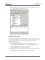
11. Click Have Disk... and direct the Device Wizard to the location of oemsetup.inf. If
you have installed the driver installer kit in the default folder, the path is:
C:\Program Files\Emulex\AutoPilot Installer\FC(or FCoE)\Drivers\Storport\x64\HBA
12. Click OK. Select Emulex LightPulse LPX000, PCI Slot X, Storport Miniport Driver
(your adapter model is displayed here).
13. Click Next.
14. Click Finish.
The driver installation has completed. The driver should start automatically. If the
adapter is connected to a SAN or data storage device, a blinking yellow light on the
back of the adapter indicates a link up condition.
Installing or Updating the iSCSI Driver
To update or install the iSCSI driver from the desktop:
1.
2.
3.
4.
5.
6.
7.
8.
Select Start>Settings>Control Panel>System.
Select the Hardware tab.
Click Device Manager.
Open the “SCSI and RAID Controllers” item.
Double-click the desired Emulex adapter.
Select the Driver tab.
Click Update Driver. The Update Driver wizard starts.
Select No, not this time. Click Next on the Welcome to the Hardware Update
Wizard window
Emulex Drivers for Windows User Manual
P010077-01A Rev. A
28
2. Installation
Manually Installing or Updating the Emulex Protocol Drivers
Note: The driver affects only the selected adapter. If there are other adapters in the
system, you must repeat this process for each adapter. All dual-channel
adapter models are displayed in Device Manager as two adapters; therefore,
you must update each adapter.
9. Select Install from a list or specific location (Advanced) and click Next.
10. Select Don't search. I will choose the driver to install and click Next.
11. Click Have Disk... and direct the Device Wizard to the location of be2iscsi.inf. If
you have installed the driver installer kit in the default folder, the path is:
C:\Program Files\Emulex\AutoPilot Installer\iSCSI\Drivers\Storport\x64\[Windows
Version]
12. Click OK. Select Emulex OneConnect OCm<your adapter model>, iSCSI Initiator.
13. Click Next.
14. Click Finish.
The driver installation has completed. The driver should start automatically.
Installing or Updating the NIC Driver
Note: The Microsoft patch KB2846340 must be installed on your system. This patch,
from Microsoft's Knowledge Base (kb), is available for Windows Server 2012,
Windows Server 2008 R2, and Windows Server 2008 SP2 on the Microsoft
website.
Windows Server 2008
1.
2.
3.
4.
5.
6.
Select Start>Settings>Control Panel>Device Manager.
Open the Network Adapters item.
Double-click the desired Emulex adapter.
Select the Driver tab.
Click Update Driver. The Update Driver wizard starts.
Click Browse my computer for driver software.
Note: The driver affects only the selected adapter. If there are other adapters in the
system, you must repeat this process for each adapter. All dual-channel
adapter models are displayed in the Device Manager as two adapters,
therefore, you must update each adapter.
7. Click Let me pick from a list of device drivers on my computer and click Next.
8. Select the network adapter that matches your hardware and click Have Disk....
9. Direct the Device Wizard to the location of be2nd6x.inf. If you have installed the
driver installer kit in the default folder, the path is:
C:\Program Files\Emulex\AutoPilot Installer\NIC\Drivers\NDIS\x64\Win2008
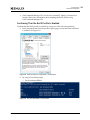
10. Click OK. The Windows Security dialog box opens.
11. Click Install.
Emulex Drivers for Windows User Manual
P010077-01A Rev. A
29
2. Installation
Removing Emulex Driver Kits and Drivers
12. When the device driver finishes installing, click Close.
The driver installation is completed. The driver should start automatically.
Windows Server 2012
1. Select Server Manager>Dashboard>Tools>Computer Management>Device
Manager.
Note: Server Manager is set to open by default when booting Windows Server
2012. If it does not open automatically, you can open it with the Server
Manager icon at the bottom left of the screen.
2.
3.
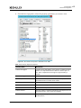
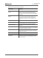
4.
5.
6.
Open the Network Adapters item.
Double-click the desired Emulex adapter.
Select the Driver tab.
Click Update Driver. The Update Driver wizard starts.
Click Browse my computer for driver software.
Note: The driver affects only the selected adapter. If there are other adapters in the
system, you must repeat this process for each adapter. All dual-channel
adapter models are displayed in the Device Manager as two adapters,
therefore, you must update each adapter.
7. Click Let me pick from a list of device drivers on my computer.
8. Select the network adapter that matches your hardware and click Have Disk....
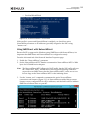
9. Direct the Device Wizard to the location of ocnd63.inf. Select the desired
oemsetup.inf file and click Open.
If you have installed the driver installer kit in the default folder, the path is:
C:\Program Files\Emulex\AutoPilot Installer\Drivers\NDIS\x64\NIC\Win2012
10. Click Next.
11. When the device driver finishes installing, click Close.
The driver installation has completed. The driver should start automatically.
Removing Emulex Driver Kits and Drivers
Uninstalling Emulex Driver Kits
Note: When you uninstall the Emulex driver kit, AutoPilot Installer is automatically
uninstalled.
Windows Server 2008
To uninstall a driver kit on a Windows Server 2008 system:
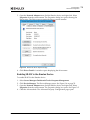
1. Open the Programs and Features control panel.
Emulex Drivers for Windows User Manual
P010077-01A Rev. A
30
2. Installation
Removing Emulex Driver Kits and Drivers
2. Select one of the following in the program list and click the Uninstall icon in the
tool bar above the program list. If you have User Access Control enabled, click
Continue when asked for permission.
Emulex FC kit-2.xx.xxx
Emulex/FCoE kit-2.xx.xxx
Emulex/NIC 4.xx.xxx
Emulex/iSCSI kit-4.xx.xxx
3. Click Yes when prompted to remove the kit. After the kit is removed from the
system, click OK.
Server Core System
To uninstall a driver kit on a Server Core system:
1. From the system prompt, navigate to the Program Files folder.
2. Navigate to Emulex\AutoPilot Installer.
3. Run the following batch files:
Uninstall_fc_kit.bat
Uninstall_cna_kit.bat
Uninstall_nic_kit.bat
Uninstall_iscsi_kit.bat
The driver files are removed from the system.
On all platforms, the reports folder in the “Emulex\AutoPilot Installer” folder is not
removed, so you can still view installation history and the drivers that have been
installed on the system. You can delete the reports folder at any time.
Windows Server 2012
To uninstall a driver kit on a Windows Server 2012 system:
1. Select Start>Control Panel.
2. From the Control Panel, select Programs>Uninstall a Program.
3. Select one of the following in the program list and click the Uninstall icon in the
tool bar above the program list. If you have User Access Control enabled, click
Continue when asked for permission.
Emulex FC kit-2.xx.xxx
Emulex/FCoE kit-2.xx.xxx
Emulex/NIC 4.xx.xxx
Emulex/iSCSI kit-4.xx.xxx
4. Click Yes when prompted to remove the kit. When the kit is removed from the
system, click OK.
Server Core System
To uninstall a driver kit on a Server Core system:
1. From the system prompt, navigate to the Program Files folder.
Emulex Drivers for Windows User Manual
P010077-01A Rev. A
31
2. Installation
Removing Emulex Driver Kits and Drivers
2. Navigate to Emulex\AutoPilot Installer.
3. Run the following batch files:
Uninstall_fc_kit.bat
Uninstall_cna_kit.bat
Uninstall_nic_kit.bat
Uninstall_iscsi_kit.bat
The driver files are removed from the system.
On all platforms, the reports folder in the “Emulex\AutoPilot Installer” folder is not
removed, so you can still view installation history and the drivers that have been
installed on the system. You can delete the reports folder at any time.
Uninstalling the Emulex Drivers
The Emulex Storport Miniport and Emulex PLUS (ElxPlus) drivers are uninstalled
using the Device Manager.
Windows Server 2008
Note: On Windows 2008, after the message “Warning – you are about to uninstall this
device from your system” is displayed, you must select Delete the software for
this device to uninstall the driver
Emulex Storport Miniport Driver
To uninstall the Emulex Storport Miniport driver:
1. Select Start>All Programs>Administrative Tools>Computer Management.
2. Click Device Manager.
3. Double-click the adapter from which you want to remove the Storport Miniport
driver. A device-specific console window is displayed. Select the Driver tab.
4. Click Uninstall and click OK to uninstall.
ElxPlus Driver
Note: Uninstall the ElxPlus driver only if all adapters and installations of Emulex
miniport drivers are uninstalled.
To uninstall the ElxPlus driver:
1.
2.
3.
4.
Run the Device Manager (steps 1 and 2 above).
Click the plus sign (+) next to the Emulex PLUS driver class.
Right-click the Emulex driver and click Uninstall.
Click OK in the Confirm Device Removal window.
Emulex Drivers for Windows User Manual
P010077-01A Rev. A
32
2. Installation
Removing Emulex Driver Kits and Drivers
Older Versions of the Emulex Storport Miniport Driver
To uninstall or update an earlier version of the Storport Miniport driver (prior to
version 1.20), you must remove the registry settings for the adjunct driver prior to
manually installing a new driver.
To remove the adjunct driver registry settings:
1. Browse to the Storport Miniport driver version 1.20 (or later) driver kit that you
downloaded and extracted.
2. Double-click on the deladjct.reg file. A Registry Editor window appears to confirm
that you want to execute deladjct.reg.
3. Click Yes. The elxadjct key is removed from the registry.
Windows Server 2012
The Emulex Storport Miniport and Emulex PLUS (ElxPlus) drivers are uninstalled
using the device manager.
Note: On Windows 2012 and Windows 2012 R2, after the message “Warning – you are
about to uninstall this device from your system” is displayed, you must select
the checkbox Delete the software for this device to uninstall the driver.
Emulex Storport Miniport Driver
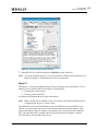
To uninstall the Emulex Storport Miniport driver in Windows Server 2012:
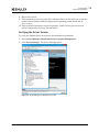
1. Select Server Manager>Dashboard>Tools>Computer Management>Device
Manager.
2. Double-click the adapter from which you want to remove the Storport Miniport
driver. A device-specific console window is displayed. Select the Driver tab.
3. Click Uninstall and click OK to uninstall.
ElxPlus Driver
Note: Uninstall the ElxPlus driver only if all adapters and installations of Emulex
miniport drivers are uninstalled.
To uninstall the ElxPlus driver:
1.
2.
3.
4.
Run the Device Manager (step 1 above).
Click the plus sign (+) next to the Emulex PLUS driver class.
Right-click the Emulex driver and click Uninstall.
Click OK in the Confirm Device Removal window.
Emulex Drivers for Windows User Manual
P010077-01A Rev. A
33
3. Configuration
FC/FCoE Driver Configuration
3. Configuration
Note: For information on configuring profile management, see the OneCommand
Manager Application User Manual or the OneCommand Manager Command Line
Interface User Manual.
FC/FCoE Driver Configuration
The Emulex Storport Miniport driver has many options that you can modify to provide
different behavior. You can set Storport Miniport driver parameters using the
OneCommand Manager application. Refer to the OneCommand Manager Application
User Manual for information on using this utility to configure the driver.
Configuring FC Driver Parameters
Table 3-1, Storport Miniport Driver Parameters, provides information such as the
allowable range of values and factory defaults. Parameters can be entered in decimal or
hexadecimal format.
A parameter has one of the following activation requirements:
Dynamic – The change takes effect while the system is running.
Reset – An adapter reset from the utility is required before the change takes
effect.
Reboot – A reboot of the entire machine is required before the change takes
effect. In this case, you are prompted to perform a reboot when you exit the
utility.
Notes:
If you are creating custom unattended installation scripts, any driver parameter
can be modified and included in the script.
If the Adapter/Protocol column is blank, the parameter is supported on both
LightPulse and OneConnect adapters. “LightPulse only” indicates that the
parameters is supported only on LightPulse adapters. “FC only” indicates that
the parameters is supported on LightPulse and non-LightPulse FC adapters.
The Windows driver enumerates 1024 targets across all physical and virtual
ports with 8G and 16G adapters. However, setting ConfigScale to 0 changes the
support to 128 targets. See “ConfigScale” in Table 3-1, Storport Miniport Driver
Parameters, on page 35.
Emulex Drivers for Windows User Manual
P010077-01A Rev. A
34
3. Configuration
FC/FCoE Driver Configuration
Most parameters default to a setting that optimizes adapter performance.
Table 3-1 Storport Miniport Driver Parameters
Parameter
Definitions
AutoMap=n
AutoMap controls the way targets are assigned
SCSI IDs. Discovered targets are assigned
persistent SCSI IDs according to the selected
binding method. Persistent bindings do not take
effect with the driver in stand-alone mode.
Activation
Requirement
Adapter/Protocol
Reboot
0 = automap is disabled. The OneCommand
Manager application persistently sets the SCSI
address of a discovered FCP capable FC node
(target).
1 = automap by WWNN.
2 = automap by WWPN.
3 = automap by DID
Value: 0–3
Default = 2
Class=n
Class selects the class of service on FCP
commands.
Dynamic
FC Only
Reset
LightPulse Only
Reset
LightPulse Only
If set to 2, class = 2.
If set to 3, class = 3.
Value: 2–3
Default = 3
CoalesceMsCnt=n
CoalesceMsCn specifies wait time in milliseconds
to generate an interrupt response if
CoalesceRspCnt has not been satisfied. Zero
specifies an immediate interrupt response
notification. A non-zero value enables response
coalescing at the specified interval in
milliseconds.
Value: 0–63 (decimal) or 0x0–0x3F (hex)
Default = 0 (0x0)
CoalesceRspCnt=n
CoalesceRspCn specifies the number of response
entries that trigger an Interrupt response.
Value: 0–255 (decimal) or 0x1–0xFF (hex)
Default = 8 (0x8)
Emulex Drivers for Windows User Manual
P010077-01A Rev. A
35
3. Configuration
FC/FCoE Driver Configuration
Table 3-1 Storport Miniport Driver Parameters (Continued)
Activation
Requirement
Parameter
Definitions
ConfigScale
ConfigScale sets the memory footprint profile in Reboot
accord with the anticipated use case on a per
port basis. While the default value is 4, a value of
1 is considered to be the typical use case. The
ConfigScale parameter supersedes the
ExtTransferSize parameter for OneConnect
adapters.
Adapter/Protocol
OneConnect and
Emulex 16-Gb
adapters
For OneConnect adapters:
For all values except 0, up to 1024 targets can be
discovered and mapped. When ConfigScale= 0,
only 128 targets can be discovered and mapped. A
value of 0 limits max XRIs to 512.
Note: Use ConfigScale = 0 to minimize the
driver's per-port memory foot print.
When ConfigScale is set to:
• 0 – the max transfer size is limited to 500 KB
• 1 – the max transfer size is limited to 1012 KB.
• 2 – the max transfer size is limited to 2036KB.
Use ConfigScale = 2 if connecting to tape
devices.
• 3 – the max transfer size is limited to 2036KB,
which is the best setting if you are running
performance benchmarks in a
non-production environment.
• 4 – the max transfer size is limited to 512KB.
Emulex 16 Gb/s adapters:
ConfigScale is always set at 4. The max transfer
size is set according to the value of the
‘ExtTransferSize’ parameter.
Values: 0, 1, 2, 3, and 4
Default = 4
Note: For Emulex 16Gb/s adapters only the value
of 4 is valid.
DiscoveryDelay=n
DiscoveryDelay controls whether the driver waits Dynamic
for ‘n’ seconds to start port discovery after link
up.
If set to 0 = immediate discovery after link up.
If set to 1 or 2 = the number of seconds to wait
after link-up before starting port discovery.
Value: 0–2 seconds (decimal)
Default = 0.
Emulex Drivers for Windows User Manual
P010077-01A Rev. A
36
3. Configuration
FC/FCoE Driver Configuration
Table 3-1 Storport Miniport Driver Parameters (Continued)
Parameter
Definitions
DriverTraceMask
The DriverTraceMask parameter is only available
on operating systems that support extended
system event logging.
Activation
Requirement
Adapter/Protocol
Dynamic
If set to 0 = the parameter is disabled.
If set to 1 = error events logging is enabled.
If set to 4 = warning events logging is enabled.
If set to 8 = informational events logging is
enabled.
The values can be masked to generate
multi-levels of events logging.
Values: 0, 1, 4, and 8.
Default = 0.
EnableAck0=n
Set to 1 to force sequence rather than frame level Reset
acknowledgement for class 2 traffic over an
exchange. This applies to FCP data exchanges on
IREAD and IWRITE commands.
FC only
Value: 0–1 (decimal)
Default = 1
EnableAUTH
EnableAUTH enables fabric authentication. This
parameter requires the authentication to be
supported by the fabric. Authentication is
enabled when this value is set to 1.
Reboot
FC only (up to and
including 8 Gb)
Value: 0–1
Default = 0
EnableFDMI=n
If set to 1, enables management server login on
fabric discovery. This allows FDMI to operate on
switches that have FDMI-capable firmware.
Reset
If set to 2, FDMI operates and uses the host name
feature of FDMI.
Value: 0–2 (decimal)
Default = 0
EnableNPIV=n
If set to 1, enables NPIV. Requires NPIV supported Reboot
firmware for the adapter.
Value: 0–1
Default = 0 (disabled)
Notes:
• To run the driver using NPIV or SLI-3
optimization, the firmware must be version
2.72a0 or later. If an earlier version is used,
the driver runs in SLI-2 mode and does not
support NPIV.
• NPIV is not available on 1 Gb/s and 2 Gb/s
adapters.
Emulex Drivers for Windows User Manual
P010077-01A Rev. A
37
3. Configuration
FC/FCoE Driver Configuration
Table 3-1 Storport Miniport Driver Parameters (Continued)
Parameter
Definitions
ExtTransferSize
ExtTransferSize is an initialization-time
parameter that affects the maximum SGL that the
driver can handle, which determines the
maximum I/O size that a port will support.
Activation
Requirement
Adapter/Protocol
LightPulse adapters
only including
LPe15000 and
LPe16000 HBAs.
If set to 0 = the maximum default transfer size is
512KB for all controller models.
If set to 1= the maximum transfer size is 1MB.
If set to 2 = the maximum transfer size is 2MB.
If set to 3 = the maximum transfer size is 4MB.
Value: 0–3
Default = 0 (disabled)
FrameSizeMSB=n
FrameSizeMSB controls the upper byte of receive Reset
FrameSize if issued in PLOGI. This allows the
FrameSize to be constrained on 256-byte
increments from 256 (1) to 2048 (8).
Value: 0–8
Default = 0
InitTimeout=n
Determines the number of time-out seconds
during driver initialization for the link to come
up. If the link fails to come up by InitTimeout,
driver initialization exits but is still successful. If
the link comes up before InitTimeout, the driver
sets double the amount for discovery to
complete.
Reboot
Value: 5–30 seconds or 0x5–0x1E (hex)
Default = 15 seconds (0xF)
LimTransferSize
Limits maximum transfer size when non-zero to
selectable values.
Reboot
Values:
0 = Port Default
1 = 64Kb
2 = 128 Kb
3 = 256Kb
Emulex Drivers for Windows User Manual
P010077-01A Rev. A
38
3. Configuration
FC/FCoE Driver Configuration
Table 3-1 Storport Miniport Driver Parameters (Continued)
Parameter
Definitions
LinkSpeed=n
LinkSpeed has significance only if the adapter
supports speeds other than one Gb/s.
Activation
Requirement
Adapter/Protocol
Reset
FC Only
Value: Auto-select, 1 Gb/s, 2 Gb/s, 4 Gb/s, 8
Gb/s
Default = Auto-select
Notes:
• Setting this option incorrectly can cause the
adapter to fail to initialize.
• If you configure the link speed in a BIOS utility,
the link speed may be overwritten by the
Windows operating system according to its
own configuration settings. To avoid this issue,
configure the link speed in both the operating
system driver and the Boot BIOS or UEFI driver.
LinkTimeOut=n
LinkTimeOut applies to a private loop only. A
Dynamic
timer is started on all mapped targets using the
link timeout value. If the timer expires before
discovery is re-resolved, commands issued to
timed out devices returns a SELECTIION_TIMEOUT.
The Storport driver is notified of a bus change
event which leads to the removal of all LUNs on
the timed out devices.
Value: 1–500 seconds or 0x0–0xFE (hex)
Default = 30 (0x1E)
LogErrors=n
LogErrors determine the minimum severity level
required to enable entry of a logged error into
the system event log. Errors are classified as
severe, malfunction or command level.
Dynamic
A severe error requires user intervention to
correct a firmware or adapter issue. An invalid
link speed selection is an example of a severe
error.
A malfunction error indicates that the system has
issues, but user intervention is not required. An
invalid fabric command type is an example of a
malfunction error.
An object allocation failure is an example of a
command error.
If set to 0 = all errors are logged.
If set to 1 = command level errors are logged.
If set to 2 = malfunction errors are logged.
If set to 3 = severe errors are logged.
Value: 0–3
Default = 3
Emulex Drivers for Windows User Manual
P010077-01A Rev. A
39
3. Configuration
FC/FCoE Driver Configuration
Table 3-1 Storport Miniport Driver Parameters (Continued)
Activation
Requirement
Parameter
Definitions
NodeTimeout=n
The node timer starts when a node (that is, a
Dynamic
discovered target or adapter) becomes
unavailable. If the node fails to become available
before the NodeTimeout interval expires, the
operating system is notified so that any
associated devices (if the node is a target) can be
removed. If the node becomes available before
NodeTimeout expires the timer is canceled and no
notification is made.
Adapter/Protocol
Value: 1–255 seconds or 0x0–0xFF (hex)
Default = 30 (0x1E)
QueueDepth=n
QueueDepth requests per LUN/target (see
Dynamic
QueueTarget parameter). If you expect the
number of outstanding I/Os per device to exceed
32, then you must increase to a value greater
than the number of expected I/Os per device (up
to a value of 254). If the QueueDepth value is set
too low, a performance degradation can occur
due to driver throttling of its device queue.
QueueDepth supports more than 1000 outstanding
commands per port.
Value: 1–254 or 0x1–0xFE (hex)
Default = 32 (0x20)
QueueTarget=n
QueueTarget controls I/O depth limiting on a per
target or per LUN basis.
Dynamic
If set to 0 = depth limitation is applied to
individual LUNs.
If set to 1 = depth limitation is applied across the
entire target.
Value: 0–1 or 0x0–0x1 (hex)
Default = 0 (0x0)
RmaDepth=n
RmaDepth sets the remote management buffer
Reboot
queue depth. The greater the depth, the more
concurrent management controls can be handled
by the local node.
Value: 8–64, or 0x8–0x40 (hex)
Default = 16 (0x10)
Note: The RmaDepth driver parameter pertains to
the functionality of the OneCommand Manager
application.
Emulex Drivers for Windows User Manual
P010077-01A Rev. A
40
3. Configuration
FC/FCoE Driver Configuration
Table 3-1 Storport Miniport Driver Parameters (Continued)
Parameter
Definitions
ScanDown=n
If set to 0 = lowest AL_PA = lowest physical disk
(ascending AL_PA order).
Activation
Requirement
Adapter/Protocol
Reboot
FC Only
Reboot
LightPulse Only
Reset
FC Only
If set to 1 = highest AL_PA = lowest physical disk
(ascending SEL_ID order).
Value: 0–1
Default = 1
Note: This option applies to private loop only in
DID mode.
SLIMode=n
If set to 0 = autoselect firmware, use the latest
firmware installed.
If set to 2 = implies running the adapter firmware
in SLI-2 mode.
If set to 3 = implies running the adapter firmware
in SLI-3 mode.
Value: 0, 2, and 3
Default = 0
SrbTimeout
SrbTimeout limits the SRB timeout value to 60
seconds when set to 1 or enabled. This is a
non-displayed parameter where it has to be set
manually into the registry. This option alters the
I/O timeout behavior where an I/O will be
returned in a max timeout of 60 seconds on some
long I/O timeout.
If set to 1 = enabled
If set to 0 = disabled
Values: 0, 1
Default = 0
Topology=n
Topology values can be 0 to 3.
If set to 0 (0x0) = FC-AL.
If set to 1 (0x1) = PT-PT fabric.
If set to 2 (0x2) = *FC-AL first, then attempt
PT-PT.
If set to 3 (0x3) = *PT-PT fabric first, then
attempt FC-AL.
* Topology fail-over requires v3.20 firmware or
higher. If firmware does not support topology
fail-over, options 0,2 and 1,3 are analogous.
Value: 0–3
Default = 2 (0x2)
Emulex Drivers for Windows User Manual
P010077-01A Rev. A
41
3. Configuration
FC/FCoE Driver Configuration
Table 3-1 Storport Miniport Driver Parameters (Continued)
Activation
Requirement
Parameter
Definitions
TraceBufSiz=n
TraceBufSiz sets the size in bytes for the internal Reboot
driver trace buffer. The internal driver trace
buffer acts as an internal log of the driver's
activity.
Adapter/Protocol
Value: 250,000–2,000,000 or 0x3D090–0x1E8480
(hex).
Default = 250,000 (0x3D090)
Server Performance with FC Drivers
I/O Coalescing
I/O Coalescing is enabled and controlled by two driver parameters: CoalesceMsCnt
and CoalesceRspCnt. The effect of I/O Coalescing depends on the CPU resources
available on the server. With I/O Coalescing turned on, interrupts are batched,
reducing the number of interrupts and maximizing the number of commands
processed with each interrupt. For heavily loaded systems, this provides better
throughput.
With I/O Coalescing turned off (the default), each I/O processes immediately, one
CPU interrupt per I/O. For systems not heavily loaded, the default provides better
throughput. The following table shows recommendations based upon the number of
I/Os per adapter.
Table 3-2 Recommended Settings for I/O Coalescing
I/Os per Second
Suggested CoalesceMsCnt
Suggested CoalesceRspCnt
I/Os < 10000
0
8
10000 < I/Os < 18000
1
8
18000 < I/Os < 26000
1
16
1/Os > 26000
1
24
CoalesceMsCnt
The CoalesceMsCnt parameter controls the maximum elapsed time in milliseconds that
the adapter waits before it generates a CPU interrupt. The value range is 0–63 (decimal)
or 0x0–0x3F (hex). The default is 0 and disables I/O Coalescing.
CoalesceRspCnt
The CoalesceRspCnt parameter controls the maximum number of responses to batch
before an interrupt generates. If CoalesceRspCnt expires, an interrupt generates for all
responses collected up to that point. With CoalesceRspCnt set to less than 2, response
coalescing is disabled and an interrupt triggers for each response. The value range for
CoalesceRspCnt is 1–255 (decimal) or 0x1–0xFF (hex). The default value is 8.
Emulex Drivers for Windows User Manual
P010077-01A Rev. A
42
3. Configuration
FC/FCoE Driver Configuration
Note:
A system restart is required to make changes to CoalesceMsCnt and
CoalesceRspCnt.
Performance Testing
There are three driver parameters that need to be considered (and perhaps changed
from the default) for better performance testing: QueueDepth, CoalesceMsCnt, and
CoalesceRspCnt.
QueueDepth
If the number of outstanding I/Os per device is expected to exceed 32, increase this
parameter to a value greater than the number of expected I/Os per device, up to a
maximum of 254. The QueueDepth parameter defaults to 32. If 32 is set and not a high
enough value, performance degradation may occur due to Storport throttling its device
queue.
CoalesceMsCnt
CoalesceMsCnt defaults to zero. If you are using a performance evaluation tool such as
IOMETER and if you expect the I/O activity to be greater than 8000 I/Os per second,
set CoalesceMsCnt to 1 and reinitialized with an adapter reset or system reboot.
CoalesceRspCnt
CoalesceRspCnt defaults to 8. For all other values up to the maximum of 63, the adapter
does not interrupt the host with a completion until either CoalesceMsCnt milliseconds
has elapsed or CoalesceRspCnt responses are pending. The value of these two driver
parameters reduces the number of interrupts per second which improves overall CPU
utilization. However, there is a point where the number of I/Os per second is small
relative to CoalesceMsCnt and this will slow down the completion process, causing
performance degradation.
Examples
Test Scenario One:
You execute IOMETER with an I/O depth of 1 I/O per device in a small-scale
configuration (16 devices). In this case, the test does not exceed the adapter 's
performance limits and the number of I/Os per second are in the low
thousands.
Recommendation: set CoalesceMsCnt to 0 (or leave the default value).
Test Scenario Two:
You execute IOMETER with an I/O depth of 48 I/Os per device in a small-scale
configuration (16 devices).
Recommendation: set QueueDepth to be greater than 48 (for example, 64).
Emulex Drivers for Windows User Manual
P010077-01A Rev. A
43
3. Configuration
NIC Driver Configuration
NIC Driver Configuration
Notes:
TOE is supported and enabled by default.
TOE is not supported on LPe16202 CFAs and OCe14000-series adapters.
Configuring NIC Driver Options
The Windows Server NIC driver supports configurable driver options through the
Advanced Property page in Windows Device Manager. For information on how to
configure the options through the Advanced Property page, see “Modifying Advanced
Properties” on page 62.
For more information on NIC driver options, see “Network Driver Performance
Tuning” on page 107.
You can also set configurable driver options using Microsoft PowerShell on Windows
Server 2012. Refer to the documentation that accompanies the Windows Server 2012
operating system for more information on using PowerShell.
See Table 3-3 on page 47 for a list of NIC driver options.
Advisory: PowerShell Behavior
Issues with Capabilities Reported by Standard PowerShell Commands
(Get-NetAdapter)
Driver parameter default registry values are initially populated from the driver
installation INF file. Thereafter, the registry is written to only if the default settings are
explicitly overridden. PowerShell uses these registry values to report capabilities with
the result that the registry values may not always reflect what is supported in the
current configuration.
The default settings can be modified through the Driver Properties page, standard
PowerShell commands, and utilities like occfg (for more information on occfg, see
“Using OCCFG for Windows NIC Driver Options” on page 68).
Standard PowerShell (Get-NetAdapter*) commands behave in the following manner:
If the feature is currently enabled, the driver reports its current capabilities.
PowerShell reports all of the feature capabilities based on what the driver
indicates. These are guaranteed to be what the NIC supports in the current
configuration.
If the feature is not enabled, the driver does not report any current capabilities.
At that point, PowerShell searches the registry for keys related to the feature
and reports their values. These are either the default values (INF) or the last
configured user values (if overwritten by the user). Default values are only
intended as maximum upper bounds; they are not guaranteed resources
supported in every configuration.
Emulex Drivers for Windows User Manual
P010077-01A Rev. A
44
3. Configuration
NIC Driver Configuration
As a result, the driver can only report a feature's current capabilities (accurate for the
present configuration), if the feature is currently enabled. However, standard
PowerShell commands will report whatever is present in the registry, when the feature
is not enabled. This can conflict with what the driver actually supports in the current
configuration.
Determining What PowerShell Is Reporting (Registry/Driver-Reported
Capabilities)
You can usually tell whether PowerShell is using capabilities reported by the driver or
is picking up registry values.
SRIOV
Check the output of Get-NetAdapterSRIOV.CurrentCapabilities for
CurrentCapabilities.
If CurrentCapabilities is empty, the driver is not currently enabled for SR-IOV.
Any reported fields in Get-NetAdapterSriov | fl * are based on registry values.
If CurrentCapabilities is not null, the driver is enabled for SR-IOV.
Get-NetAdapterSriov fields are based on what the driver reports.
NetAdapter*) commands behave in this manner.
RDMA
Check the output of Get-NetAdapterRdma.RdmaAdapterInfo for
RdmaAdapterInfo.
If RdmaAdapterInfo is empty, any reported fields in Get-NetAdapterRdma | fl
* are based on registry values. If RdmaAdapterInfo is not null, the driver is
reporting RDMA capabilities. Get-NetAdapterRdma fields are based on what
the driver reports.
Considerations for Using UMC and NIC
Note: UMC is not supported on LPe16202 CFAs.
64 VLAN IDs can be used with each UMC virtual channel.
SR-IOV must be disabled when using UMC because it is not supported.
For additional information on UMC, refer to the Emulex Universal Multichannel Reference
Guide, which is available for download from the Emulex website.
ARI Considerations
Note: RoCE is not supported with ARI.
The PCIe standard limits an adapter to a maximum of 8 physical functions. This means
that a 2-port adapter can only have 4 functions per port and a 4 port adapter can only
have 2 functions per port. The following requirements must be met to fully support
ARI and expose more than 8 functions on an adapter:
Emulex Drivers for Windows User Manual
P010077-01A Rev. A
45
3. Configuration
NIC Driver Configuration
ARI must be available on the system to support up to sixteen functions on an
adapter. If these conditions are not met, although you may configure all sixteen
functions, only eight functions will be present and discovered by the
OneCommand Manager application after a reboot.
Only OCe14000-series adapters support ARI.
The system hardware, such as the motherboard and BIOS, must support ARI.
ARI must be enabled in the system BIOS.
The operating system must support ARI, such as the Windows Server 2012
and later.
Any management tools that you use must support ARI, such as OneCommand
Manager 10.2 and later.
For Dell multichannel support, see “NPar Configuration (Dell Only)” on page 99.
Emulex Drivers for Windows User Manual
P010077-01A Rev. A
46
3. Configuration
NIC Driver Configuration
Table 3-3 Windows Server 2008, Windows Server 2008 R2, Windows Server 2012, and Windows Server 2012 R2 NIC
Driver Options
Option Name
Acceptable Values
Supported Operating
Systems
Class of Service
(802.1p)
Automatic Priority (default)
Windows Server 2008
Filtered Priority
Windows Server 2008 R2
User Priority
Windows Server 2012
Disable Priority
Windows Server 2012 R2
Emulex Drivers for Windows User Manual
Definition
The following modes are
supported for selecting 802.1p
priority tags:
• Automatic Priority – The DCBX
standard allows the network
adapter to negotiate priority
class usage with DCBX aware
endpoints such as switches or
network cards. If the peer
indicates that priority pause is
supported for a non-zero
priority, the NIC automatically
inserts the default priority in
all transmitted packets. This is
the default mode, allowing
priority pause to operate for
both storage and network
traffic. If the peer indicates a
zero default priority (such as
when the peer does not support
priority pause), the device uses
the “Non-Storage Priority”
mode discussed below.
• Filtered Priority – This mode
coerces the user priorities in
each packet to avoid sending
packets on the network
function that may disrupt the
converged adapter's storage
traffic. The network device
uses the next lower priority if a
conflict exists. This mode is
useful if multiple network
priorities are necessary. Only a
limited number of classes are
supported for priority pause, so
typically it does not function
optimally in this mode.
• User Priority – This mode allows
any user specified priority
value and should be limited to
cases where storage functions
are not used.
• Disable Priority – The adapter
always transmits either
untagged packets, or VLAN ID
(802.1q) tagged packets with a
priority value (802.1p) of zero.
P010077-01A Rev. A
47
3. Configuration
NIC Driver Configuration
Table 3-3 Windows Server 2008, Windows Server 2008 R2, Windows Server 2012, and Windows Server 2012 R2 NIC
Driver Options (Continued)
Option Name
Acceptable Values
Supported Operating
Systems
Enhanced
Transmission
Selection
Disabled (default)
Windows Server 2008
Enabled
Definition
If ETS is enabled, the driver filters
Windows Server 2008 R2 transmit packets based on the
802.1p priority tag into multiple
Windows Server 2012
separate transmit rings. The
Windows Server 2012 R2 network switch should be
configured for ETS to group
priorities into a priority group (or
Notes:
traffic class). Each priority group
• For OCe11102 UCNAs
may be assigned a QoS bandwidth
only.
limit. For example, one network
• ETS is not supported in priority may to support priority
conjunction with VMQ flow control to achieve loss-less
technology. ETS is not network traffic. Using separate
available if SR-IOV is
hardware interfaces in the driver
enabled.
allows each priority to progress at
a different rate, or pause
temporarily without affecting the
other priorities.
When ETS is enabled, all
configurations regarding
bandwidth and priority flow
control should be performed on
the network switch. The adapter
will learn the configuration using
the DCBx protocol.
Flow Control
Disabled
Windows Server 2008
RX and TX Enabled (default)
Windows Server 2008 R2
Rx Enable/Tx Disable
Windows Server 2012
Tx Enable/Rx Disable
Windows Server 2012 R2
Flow control is almost always
advantageous to avoid packet
drops on the network. The switch
or network peer must also have
flow control enabled.
The IEEE 802.3x Ethernet
specification defines a control
frame between peers that can
request a pause in packet
transmissions. This allows one
system to request a temporary
halt of all incoming traffic when
receive buffer space is exhausted.
The network device may be
configured to respond to pause
frames (Rx Enable) and/or to send
pause frames (Tx Enable).
IP Checksum
Offload (IPv4)
Disabled
Windows Server 2008
RX and TX Enabled (default)
Windows Server 2008 R2
RX Enabled
Windows Server 2012
TX Enabled
Windows Server 2012 R2
Emulex Drivers for Windows User Manual
This offloads the transmit and/or
receive IPv4 checksum
computation.
Offloading checksums increases
system efficiency.
P010077-01A Rev. A
48
3. Configuration
NIC Driver Configuration
Table 3-3 Windows Server 2008, Windows Server 2008 R2, Windows Server 2012, and Windows Server 2012 R2 NIC
Driver Options (Continued)
Option Name
Acceptable Values
Supported Operating
Systems
Large Send Offload
v1 (IPv4)
Disabled
Windows Server 2008
Enabled (default)
Windows Server 2008 R2
Windows Server 2012
Windows Server 2012 R2
Definition
Large Send Offload allows the NIC
hardware to segment large TCP
packets (up to 64kB) into smaller
packets (<= “Packet Size”) that
may be transmitted. This
segmentation increases transmit
efficiency for TCP applications
that send large buffers. During
segmentation, the hardware
computes the IPv4 and TCP
checksums for each individual
packet.
The Windows Version 1 LSO
supports only IPv4.
Large Send Offload
v2 (IPv4)
Disabled
Windows Server 2008
Enabled (default)
Windows Server 2008 R2
Windows Server 2012
Windows Server 2012 R2
Large Send Offload allows the NIC
hardware to segment large TCP
packets (up to 64kB) into smaller
packets (<= “Packet Size”) that
may be transmitted. This
segmentation increases transmit
efficiency for TCP applications
that send large buffers. During
segmentation, the hardware
computes the IPv4 and TCP
checksums for each individual
packet.
The Windows Version2 LSO
supports larger offload sizes.
Large Send Offload
v2 (IPv6)
Disabled
Windows Server 2008
Enabled (default)
Windows Server 2008 R2
Windows Server 2012
Windows Server 2012 R2
Large Send Offload allows the NIC
hardware to segment large TCP
packets (up to 64kB) into smaller
packets (less than the MTU) that
may be transmitted. This
segmentation increases transmit
efficiency for TCP applications
that send large buffers. During
segmentation, the hardware
computes the TCP checksums for
each individual packet.
IPv6 support requires LSO Version
2, included in Windows Server
2008 and later.
Maximum Number
of RSS Processors
Min: 0
Windows Server 2008
Max: The number CPU cores
installed on your system.
Windows Server 2008 R2
Windows Server 2012
This property sets the maximum
number of processors that can be
used for RSS.
Windows Server 2012 R2
Emulex Drivers for Windows User Manual
P010077-01A Rev. A
49
3. Configuration
NIC Driver Configuration
Table 3-3 Windows Server 2008, Windows Server 2008 R2, Windows Server 2012, and Windows Server 2012 R2 NIC
Driver Options (Continued)
Option Name
Acceptable Values
Maximum Number
of RSS Queues
Windows Server 2008; for
OCe10102, OCe11102 legacy,
OCe11102 advanced mode,
LPe16000, OCe14000:
• Min 1, Max 4, default 4
Supported Operating
Systems
Windows Server 2008
Windows Server 2008 R2
Windows Server 2012
Windows Server 2012 R2
Windows Server 2008 R2,
Windows Server 2012,
Windows Server 2012 R2;
• OCe10102: Min 1, Max 4,
Default 4
• OCe11102, legacy: Min 1,
Max 4, Default 4
• OCe11102, advanced
mode: Min 1, Max 8,
Default 8
• LPe16000: Min 1, Max 16,
default 8
• OCe14000: Min 1, Max 16,
default 8
Maximum RSS
Processor Number
Network Address
Definition
When RSS is enabled, this
parameter controls the number of
receive queues. Typically, this is
left at the maximum value.
Windows reduces the number of
queues as necessary based on the
number of installed CPU cores.
This value may be reduced during
performance tuning for a
particular application. It is
possible that system performance
may improve by limiting the
number of RSS queues.
For OCe11102, greater than 4 RSS
queues requires Advanced Mode
Support be enabled in the BIOS
controller configuration.
Min: 1
Windows Server 2008
Max: The number of CPU
cores installed on your
system.
Windows Server 2008 R2
Valid MAC Address
Windows Server 2008
The default setting is None.
Windows Server 2008 R2
Windows Server 2012
Windows Server 2012 R2
Windows Server 2012
Windows Server 2012 R2
This parameter sets the maximum
processor number for the RSS
CPUs. This is the highest processor
number of any processors from the
RSSMaxProcGroup parameter.
This overrides the permanent MAC
address for the interface. The MAC
address should follow this format
XX:XX:XX:XX:XX:XX, where X is a
hex digit (0-9 or A-F).
• The address cannot be a
multicast address, which has
the lowest bit in the first byte
set.
• The address cannot be all
zeros.
For example, 01:00:00:00:00:00 is
not valid, while 02:00:00:00:00:00
is valid.
Emulex Drivers for Windows User Manual
P010077-01A Rev. A
50
3. Configuration
NIC Driver Configuration
Table 3-3 Windows Server 2008, Windows Server 2008 R2, Windows Server 2012, and Windows Server 2012 R2 NIC
Driver Options (Continued)
Option Name
Acceptable Values
Supported Operating
Systems
NetworkDirect
0—Disabled
Windows Server 2012 R2
1—Enabled (default)
Definition
The Network Direct feature
enables an offloaded RDMA
interface for SMB 3.0 network
attached storage traffic using
Microsoft's SMB Direct protocol.
For best performance, priority
flow control (PFC) should be
configured on the network switch.
Emulex defaults to priority (PFC) 5
for ROCE traffic, although it will
still work without PFC enabled.
Windows Server 2012 R2
The maximum transmission unit
(MTU) or frame size for ROCE
traffic may be configured with this
parameter.
NVGRE Task Offload Disabled
Windows Server 2012
(also known as
Encapsulated Task
Offload)
Enabled (default)
Windows Server 2012 R2
NVGRE Task Offload enables the
offloading of network
virtualization using GRE tunneling
on the NIC adapter. NVGRE offload
works in conjunction with VMQ.
Packet Size
1514 (default)
Windows Server 2008
9014
Windows Server 2008 R2
8222
Windows Server 2012
4088
Windows Server 2012 R2
Network Direct MTU 256
512
1024 (default)
2048
4096
Note: For
OCe14000-series
adapters only.
Configures packet size for
OneConnect NIC only.
This parameter determines the
maximum packet size transmitted
and received on the interface. A
1514 byte frame size is standard,
while larger packets are called
jumbo frames.
Using a higher frame size is
generally more efficient, but it
uses more system memory. A
larger frame size also requires
support on the network switch.
Jumbo frames are IPv4-only
frames; IPv6 packets will be
fragmented by LSO. Switches and
the peer should be configured to
accept the specified packet size or
the size will be negotiated to the
common smallest size.
Emulex Drivers for Windows User Manual
P010077-01A Rev. A
51
3. Configuration
NIC Driver Configuration
Table 3-3 Windows Server 2008, Windows Server 2008 R2, Windows Server 2012, and Windows Server 2012 R2 NIC
Driver Options (Continued)
Option Name
Acceptable Values
Performance Tuning • Maximum performance
(default)
• Dynamically balanced
• Statically balanced
Emulex Drivers for Windows User Manual
Supported Operating
Systems
Windows Server 2012
Definition
This parameter selects the driver
algorithm for performance tuning,
allowing you to balance raw
networking throughput with
overall system fairness among
multiple devices and applications.
• Maximum Performance - This
mode maximizes the network
performance for this adapter.
This is the recommended
mode. However, in systems
with a large number of network
or storage adapters, this mode
may limit the performance of
other devices.
• Statically Balanced - This mode
configures the network adapter
to throttles CPU usage in all
cases, allowing more balance
among hardware devices and
applications. If system
responsiveness is poor, this
mode may improve the overall
system behavior.
• Dynamically Balanced Dynamic balancing adjusts the
network adapter's performance
based on system metrics, such
as CPU usage. This mode can
aggressively limit performance
for the most stressful
networking applications to
ensure that all network
adapters can share limited
computer resources, yet it can
maintain maximum
performance when the system
has resources available.
P010077-01A Rev. A
52
3. Configuration
NIC Driver Configuration
Table 3-3 Windows Server 2008, Windows Server 2008 R2, Windows Server 2012, and Windows Server 2012 R2 NIC
Driver Options (Continued)
Option Name
Acceptable Values
Preferred NUMA
Node
Not present or a value from
0–65535.
Supported Operating
Systems
Windows Server 2008
Windows Server 2008 R2
Optional. No default setting is Windows Server 2012
set.
Windows Server 2012 R2
Definition
Most modern multi-socket servers
have separate memory controllers
for each CPU socket. These
systems have non-uniform memory
access (NUMA) latencies for a
given CPU core to access the local
versus remote memory node.
By setting this property, the driver
attempts to use both memory and
CPU cores from the given NUMA
node.
If the Preferred NUMA node is not
set, the driver uses the preferred
NUMA node as specified by the
computer's BIOS.
For best performance, the
network applications should try to
use memory and CPU affinity from
the same NUMA node. This level of
tuning is primarily noticeable
when multiple adapters are
running.
Receive Buffers
64–16384, inclusive
Windows Server 2008
The default value is 896.
Windows Server 2008 R2
Windows Server 2012
Windows Server 2012 R2
Receive CPU
“Not Present” or a value from Windows Server
0 through (number of CPUs on Windows Server
the system-1).
Windows Server
Optional. There is no default
Windows Server
setting.
Emulex Drivers for Windows User Manual
2008
2008 R2
2012
2012 R2
This determines the number of
Ethernet receive buffers allocated
per receive queue. This number
may be adjusted by the driver as
needed.
Sets the logical CPU used for
processing the non-RSS receive
packets. By default, the driver
intelligently chooses a CPU in the
system, so this parameter should
only be used for advanced
performance tuning. RSS packets
are processed by the set of RSS
CPUs provided by the Windows
operating system.
P010077-01A Rev. A
53
3. Configuration
NIC Driver Configuration
Table 3-3 Windows Server 2008, Windows Server 2008 R2, Windows Server 2012, and Windows Server 2012 R2 NIC
Driver Options (Continued)
Option Name
Acceptable Values
Receive Side Scaling Disabled
Enabled (default)
Supported Operating
Systems
Windows Server 2008
Windows Server 2008 R2
Windows Server 2012
Windows Server 2012 R2
Definition
Support for multiple RSS queues if
enabled.
RSS scales receive processing over
multiple CPUs in parallel. This
scaling typically improves
application performance;
however, it tends to increase CPU
usage on low end machines.
For the OCe11102 adapter, RSS is
only supported on two primary
adapters per device.
For additional PCI functions, RSS
does not appear in the Properties
List.
Recv Segment
Coalescing (IPv4)
Disabled (default on Windows Windows Server
Server 2008, Windows Server Windows Server
2008 R2)
Windows Server
Enabled (default on Windows
Windows Server
Server 2012)
2008
2008 R2
2012
2012 R2
RSC merges multiple TCP segments
and identifies them as a single
coalesced unit to the operating
system's TCP/IP stack. This
reduces the per-packet receive
processing overhead and CPU
usage when standard 1514 byte
sized frames are in use.
Notes:
• If checksum offloads are
disabled, RSC should also be
disabled. RSC depends on
checksum offloads for better
performance.
• Both RSC (IPV4) and RSC (IPV6)
are coerced to zero if TCP
Connection Offload (IPV4) is
enabled.
Emulex Drivers for Windows User Manual
P010077-01A Rev. A
54
3. Configuration
NIC Driver Configuration
Table 3-3 Windows Server 2008, Windows Server 2008 R2, Windows Server 2012, and Windows Server 2012 R2 NIC
Driver Options (Continued)
Supported Operating
Systems
Option Name
Acceptable Values
Recv Segment
Coalescing (IPv6)
Disabled (default on Windows Windows Server
Server 2008, Windows Server Windows Server
2008 R2)
Windows Server
Enabled (default on Windows
Windows Server
Server 2012)
2008
2008 R2
2012
2012 R2
Definition
RSC merges multiple TCP segments
and identifies them as a single
coalesced unit to the operating
system's TCP/IP stack. This
reduces the per-packet receive
processing overhead and CPU
usage when standard 1514 byte
sized frames are in use.
Notes:
• If checksum offloads are
disabled, RSC should also be
disabled. RSC depends on
checksum offloads for better
performance.
• Both RSC (IPV4) and RSC (IPV6)
are coerced to zero if TCP
Connection Offload (IPV4) is
enabled.
RSS Base Processor
Group
Min: 1
Windows Server 2012
Max: 63
This defines the base processor
group for the RSS queues on the
network adapter. A processor
group contains 64 logical
processors.
This value may be modified in
conjunction with the “RSS Base
Processor Number” to explicitly
select the desired RSS processors
for the adapter.
RSS Base Processor
Number
Min: 1
Windows Server 2012
Max: 63
This defines the base processor
number for the RSS queues on the
network adapter within the given
processor group. A processor
group contains 64 logical
processors, so this value ranges
from 0 to 63.
This value may be modified in
conjunction with the “RSS Base
Processor Group” to explicitly
select the desired RSS processors
for the adapter.
RSS Max Processor
Group
Min: 0
Max: The number of processor
groups present on your
system.
Emulex Drivers for Windows User Manual
Windows Server 2012
RSS Max Processor Group allows
you to set the maximum number of
processor groups for the RSS CPUs
P010077-01A Rev. A
55
3. Configuration
NIC Driver Configuration
Table 3-3 Windows Server 2008, Windows Server 2008 R2, Windows Server 2012, and Windows Server 2012 R2 NIC
Driver Options (Continued)
Option Name
Acceptable Values
Supported Operating
Systems
RSS Profile
Closest processor (default)
Windows Server 2012
The RSS Profile setting determines
the RSS load balancing profile
implemented by Microsoft for this
network adapter. The “Closest
Processor” settings will tend to
localize the RSS CPUs to one NUMA
node, allowing the device driver to
allocate memory from the local
node.
The “NUMA Scaling” settings will
use all NUMA nodes on the system,
and the memory allocation will not
be specific to a particular node.
The driver will ignore the
Preferred NUMA node setting.
AutoNeg (default)
Windows Server 2008
10GbpsFullDuplex
Windows Server 2008 R2
1GbpsFullDuplex
Windows Server 2012
SpeedDuplex is used for selecting
link speed, mainly for 10G BaseT
Adapters. When it is set to the
default, it auto negotiates
100Mbps/1Gbps/10Gbps with
switch/peer.
Closest processor static
NUMA scaling
NUMA scaling static
Conservative scaling
SpeedDuplex
Windows Server 2012 R2
Definition
Link speed can be forced to
1Gbps, if option 1.0Gbps Full
Duplex is selected.
Link speed can be forced to
10Gbps, if option 10Gbps Full
Duplex is selected. 10Gbps is
the maximum supported link
speed.
Emulex Drivers for Windows User Manual
P010077-01A Rev. A
56
3. Configuration
NIC Driver Configuration
Table 3-3 Windows Server 2008, Windows Server 2008 R2, Windows Server 2012, and Windows Server 2012 R2 NIC
Driver Options (Continued)
Option Name
Acceptable Values
SR-IOV
Disabled (default)
Enabled
Supported Operating
Systems
Note: For OCe11102,
LPe16202, and
OCe14000-series
only.
Windows Server 2012
Windows Server 2012 R2
Definition
SR-IOV enables the adapter to
allocate virtual PCI functions for
each virtual machine in Hyper-V.
Note that the virtual switch and
virtual network adapter must have
SR-IOV enabled in the Hyper-V
Manager. SR-IOV requires a
platform with IOMMU
virtualization (VT-d, AMD-Vi).
When using SR-IOV, the Emulex NIC
driver must be installed on each
virtual function within the virtual
machine. SR-IOV provides a direct
hardware interface from the
virtual machine to the networking
adapter, which reduces latency
and improves performance.
The Windows Server 2012 and
Windows Server 2012 R2 SR-IOV
architecture establishes each
Emulex virtual NIC with a
corresponding emulated NIC. This
allows the virtual machine to
seamlessly failover to the
emulated NIC if SR-IOV is disabled.
It also allows Live Migration to
another system, regardless of the
installed NIC hardware.
Note: The driver currently
supports the following
virtual functions for the
following adapter families:
Emulex Drivers for Windows User Manual
OCe11100-series adapters
support a maximum of 24
virtual functions/port.
OCe14000-series adapters
support a maximum of:
2-port 10 Gb: 31 virtual
functions/physical
function.
4-port 10 Gb: 31 virtual
functions/physical
function
1-port 40 Gb: 63 virtual
functions/physical
function
P010077-01A Rev. A
57
3. Configuration
NIC Driver Configuration
Table 3-3 Windows Server 2008, Windows Server 2008 R2, Windows Server 2012, and Windows Server 2012 R2 NIC
Driver Options (Continued)
Option Name
Acceptable Values
Supported Operating
Systems
TCP Checksum
Offload (IPv4)
Disabled
Windows Server 2008
RX and TX Enabled (default)
Windows Server 2008 R2
RX Enabled
Windows Server 2012
TX Enabled
Windows Server 2012 R2
Disabled
Windows Server 2008
RX and TX Enabled (default)
Windows Server 2008 R2
RX Enabled
Windows Server 2012
TX Enabled
Windows Server 2012 R2
TCP Checksum
Offload (IPv6)
Emulex Drivers for Windows User Manual
Definition
TCP Checksum Offload (IPv4)
offloads the transmit and/or
receive IPv4 TCP checksum
computation. Offloading
checksums increases system
efficiency.
TCP Checksum Offload (IPv6)
offloads the transmit and/or
receive IPv6 TCP checksum
computation. Offloading
checksums increases system
efficiency.
P010077-01A Rev. A
58
3. Configuration
NIC Driver Configuration
Table 3-3 Windows Server 2008, Windows Server 2008 R2, Windows Server 2012, and Windows Server 2012 R2 NIC
Driver Options (Continued)
Option Name
Acceptable Values
Supported Operating
Systems
TCP Connection
Offload (IPv4)
Enabled
Windows Server 2008
Disabled (default)
Windows Server 2008 R2
Windows Server 2012
Windows Server 2012 R2
Definition
Note: TCP Connection Offload is
not supported on 16Gb
UCNAs.
If TCP offload is enabled, the
device offloads the entire TCP
protocol, including ACK
processing, retransmits, and
timers. Applications that prepost
receive buffers (before the data
arrives) may avoid data copies in
the receive path, which
substantially increases the system
efficiency and data rates.
Windows does not offload TCP
connections if any of the following
are enabled:
• Network Load Balancing
• IPSEC
• Network Address Translation
• NDIS 5.1 Intermediate Drivers
TCP offload must be enabled in
the Windows operating system
with the shell command:
netsh int tcp set
global chimney=enabled
This parameter appears disabled if
the firmware installed on your
device does not support TCP
connection offload. Upgrading the
firmware may resolve this issue.
View the “Statistics” property
page to ensure that TCP
connection offload is working.
Note: Both RSC (IPV4) and RSC
(IPV6) are coerced to zero if
TCP Connection Offload
(IPV4) is enabled.
Emulex Drivers for Windows User Manual
P010077-01A Rev. A
59
3. Configuration
NIC Driver Configuration
Table 3-3 Windows Server 2008, Windows Server 2008 R2, Windows Server 2012, and Windows Server 2012 R2 NIC
Driver Options (Continued)
Option Name
Acceptable Values
Supported Operating
Systems
TCP Offload
Optimization
Optimize Latency
Windows Server 2008
Optimize Throughput
(default)
Windows Server 2008 R2
Windows Server 2012
Windows Server 2012 R2
Definition
This parameter only applies to TCP
connection offload, which must be
enabled in the “Protocol Offloads”
section.
Most applications perform better
with TCP Offload Optimization set
to “Optimize Throughput” which
handles large data transfers with
minimal CPU impact.
Setting this parameter to
“Optimize Latency” causes receive
data to be delivered to the
application without waiting for a
TCP PSH. This causes additional
receive indications that typically
decrease total throughput.
Transmit Buffers
64–256, inclusive
Windows Server 2008
The default setting is 256.
Windows Server 2008 R2
Windows Server 2012
Windows Server 2012 R2
Transmit CPU
Transmit Side
Scaling (TSS)
“Not Present” or a value from Windows Server
0 through (number of CPUs
Windows Server
-1).
Windows Server
Optional. There is no default
Windows Server
setting.
2008
2008 R2
2012
2012 R2
Enabled
Windows Server 2008
Disabled
Windows Server 2008 R2
Windows Server 2012
Windows Server 2012 R2
UDP Checksum
Offload (IPv4)
Disabled
Windows Server 2008
RX and TX Enabled (default)
Windows Server 2008 R2
RX Enabled
Windows Server 2012
TX Enabled
Windows Server 2012 R2
Emulex Drivers for Windows User Manual
Transmit Buffers sets the number
of Ethernet transmits that may be
posted to the hardware at any
given time.
The default value is sufficient to
achieve maximum performance.
Reducing this value conserves
system memory.
Sets the CPU to be used to process
transmit completions. By default,
the driver intelligently chooses a
CPU in the system, so this
parameter should only be set for
advanced performance tuning.
TSS distributes transmit
completions to be processed on
multiple CPUs in parallel. It uses
the RSS CPU table for distribution
and therefore requires RSS to be
enabled.
UDP offload checksum settings
offload the transmit and/or
receive IPv4 UDP checksum
computation.
Offloading checksums increases
system efficiency.
P010077-01A Rev. A
60
3. Configuration
NIC Driver Configuration
Table 3-3 Windows Server 2008, Windows Server 2008 R2, Windows Server 2012, and Windows Server 2012 R2 NIC
Driver Options (Continued)
Option Name
Acceptable Values
Supported Operating
Systems
UDP Checksum
Offload (IPv6)
Disabled
Windows Server 2008
RX and TX Enabled (default)
Windows Server 2008 R2
RX Enabled
Windows Server 2012
TX Enabled
Windows Server 2012 R2
Enabled (default)
Note: For OCe11102,
LPe16202, and
OCe14000 only.
Virtual Machine
Queues
Disabled
VMQs require Windows
Server 2008 R2 or later
with Hyper-V.
Definition
User Datagram Protocol (UDP)
offload checksum settings offload
the transmit and/or receive IPv6
UDP checksum computation.
Offloading checksums increases
system efficiency.
VMQs are dedicated hardware
receive queues for virtual
machines that filter receive
packets based on the destination
MAC address and/or VLAN. Receive
buffers can be allocated for each
queue from VM memory.
This improves network throughput
by distributing processing of
network traffic for multiple VMs
among multiple processors. It
reduces CPU utilization by
offloading receive packet filtering
to NIC hardware. VMQs prove
beneficial when 4 or more VMs are
in use.
Virtual Machine
Queues Lookahead
Split
Enabled (default)
Disabled
Note: For OCe11102
UCNAs only. Not
applicable for
LPe16202 and
OCe14000-series
adapters.
Windows Server 2008 R2
VMQ enables direct DMA to VM
memory. Lookahead improves
packet steering performance by
PCI prefetching adjacent header
buffer into a cache when
examining a packet. Header
buffers are continuous in physical
memory since they belong to one
pool.
For OCe11102, Lookahead split
requires Advanced Mode Support
and is enabled in the BIOS
controller configuration.
Note: Lookahead split is not
supported for jumbo
frames.
Virtual Machine
Queues Transmit
Enabled (default)
Disabled
Note: For OCe11102,
LPe16202, and
OCe14000-series
adapters only.
Windows Server 2008 R2
Windows Server 2012
Windows Server 2012 R2
Emulex Drivers for Windows User Manual
If this option is enabled with
VMQs, separate transmit queues
are created for each VM network
interface. Send and receive
interrupts for a VM network
interface are processed on the
same CPUs.
Separate transmit queues increase
system overall CPU utilization, but
offer greater system scalability.
P010077-01A Rev. A
61
3. Configuration
NIC Driver Configuration
Table 3-3 Windows Server 2008, Windows Server 2008 R2, Windows Server 2012, and Windows Server 2012 R2 NIC
Driver Options (Continued)
Option Name
Acceptable Values
Supported Operating
Systems
VLAN Identifier
(802.1q)
Not Present (default)
Windows Server 2008
1 to 4094
Windows Server 2008 R2
Windows Server 2012
Windows Server 2012 R2
Wake on LAN
Enabled (default)
Windows Server 2008
Disabled
Windows Server 2008 R2
Notes:
Windows Server 2012
• For Windows Server 2012 Windows Server 2012 R2
inbox drivers, “Wake on
Note: For OCe11102 only.
LAN” is disabled by
default and not
overwritten on driver
updates.
• “Wake on LAN” is disabled
by default on
OCe10102-series adapters.
Definition
If selected, the adapter adds a
VLAN tag to all transmitted
packets, and only receives packets
with the matching VLAN tag.
Notes:
• This property should not be
used when the Emulex Teaming
Driver is enabled. In that case,
VLAN configuration should be
performed in the Teaming
Driver application.
• This property should not be
used with Hyper-V. In that
case, the Microsoft Hyper-V
Manager should be used to
configure VLANs on each virtual
machine.
Enabling “Wake on LAN” allows
the network device to wake up the
computer when a magic packet is
received during standby.
In Blade server configurations,
“Wake On Lan” is only supported
on two primary adapters per
device. Additional PCI functions
appear disabled.
Configuring Windows Server NIC Driver Parameters
The Windows Server NIC drivers support driver options through the Advanced
Property page in Windows Device Manager.
Modifying Advanced Properties
Modify the advanced properties for the driver for Windows with the Windows Device
Manager. For more information on advanced properties, see “Network Driver
Performance Tuning” on page 107.
To modify the advanced properties:
1. Enter the Windows Device Manager using one of the following options:
Click Start> Control Panel>System and click the Device Manager hyperlink.
Click Start>Run, and type devmgmt.msc.Click OK.
Emulex Drivers for Windows User Manual
P010077-01A Rev. A
62
3. Configuration
NIC Driver Configuration
The Windows Device Manager is displayed.
Figure 3-1 Partial View of Windows Device Manager
2. Right-click the network adapter for which you wish to modify advanced properties.
3. Click Properties, and click the Advanced tab (Figure 3-2 on page 64).
4. From the list of properties, click the property (parameter) you want to modify, then
select the new value of the property by selecting from the Value list.
5. Click OK.
Emulex Drivers for Windows User Manual
P010077-01A Rev. A
63
3. Configuration
NIC Driver Configuration
Note: Modifying properties causes the network driver to reload and some TCP
connections may be temporarily dropped.
Figure 3-2 NIC Advanced Properties in Windows Server 2008
Statistics Property Page
Use the Statistics Properties tab to view the performance of the device and network. By
viewing the statistics properties, you can troubleshoot issues and performance tune the
system, for example you can assess how different device properties change the
performance of the system.
To view the statistics properties:
1. Enter the Windows Device Manager using one of the following options:
Click Start> Control Panel>System and click the Device Manager hyperlink.
Click Start>Run, then type devmgmt.msc and click OK.
The Windows Device Manager is displayed (Figure 3-1).
2. Right-click the network adapter for which you wish to view the statistics properties.
3. Click Properties, then click the Statistics tab (Figure 3-3 on page 65).
Emulex Drivers for Windows User Manual
P010077-01A Rev. A
64
3. Configuration
NIC Driver Configuration
4. From the list of properties, select the property (parameter) you want to view.
Figure 3-3 NIC Statistics Properties in Windows Server 2008
Table 3-4 NIC Driver Properties Statistics
Statistic Name
Description
Transmit Throughput
The data rate for this adapter on the network, including all packet
headers. It is expressed in terms of bits/sec, where 1 byte = 8
bits. This is computed as the average over approximately 3
seconds.
Receive Throughput
The receive rate for this adapter.
Transmit Bytes
The total number of bytes transmitted by this adapter, since the
last statistics reset or the last driver reload.
Receive Bytes
The total number of bytes received by this adapter.
Transmit Packet Rate
The rate of transmit packets for the adapter.
Receive Packet Rate
The rate of receive packets for the adapter.
Transmit Packets
The total number of packets transmitted by the adapter since the
last statistics reset, or the driver was reloaded.
Receive Packets
The total number of packets received. This includes both RSS and
non-RSS packets.
Emulex Drivers for Windows User Manual
P010077-01A Rev. A
65
3. Configuration
NIC Driver Configuration
Table 3-4 NIC Driver Properties Statistics (Continued)
Statistic Name
Description
RSS Receive Packets
The number of receive packets that were suitable for RSS.
Transmit Flow Control Pause
Requests
The number of times the network adapter sent a PAUSE frame to
request that the peer stop sending data temporarily. This
indicates a potential bottleneck in the system. Typically, this
bottleneck is the result of the DMA of packets from the adapter to
host memory.
Receive Flow Control Pause
Requests
The number of times the network adapter received a PAUSE frame
from the peer. This indicates a potential bottleneck in the
attached switch or network peer device. This statistic only
increments when the switch is correctly configured for flow
control.
TCP Offloads Current Established
The current number of TCP connections offloaded to the adapter's
TOE.
TCP Offloads
The total number of TCP connections that have been offloaded
since the last statistics reset, or the driver was reloaded.
TCP Offload Retransmits
The number of packets retransmitted for TCP offloaded
connections.
TCP Offload Receive Drops
The number of packets dropped by in the offloaded TCP stack.
These drops may the result of TCP protocol errors or bottlenecks
in the system for consuming receive data.
TCP Offload Transmit Rate
The transmit data rate of the offloaded TCP connections. This is
the portion of the total “Transmit Throughput” contributed by
offloaded TCP connections.
TCP Offload Receive Rate
The receive data rate of the offloaded TCP connections.
VMQs Allocated
The current number of Virtual Machine Queues allocated.
Interrupt Rate
The number of interrupts per second generated by the adapter.
The interrupt rate may be tuned by modifying the Interrupt
Moderation parameter.
Emulex Drivers for Windows User Manual
P010077-01A Rev. A
66
3. Configuration
NIC Driver Configuration
Table 3-4 NIC Driver Properties Statistics (Continued)
Statistic Name
Description
Receive Drops No Memory (DMA
Limited)
The number of packets dropped as a result of insufficient buffers
posted by the driver. This is generally the result of the CPU core
used for any receive queue reaching 100%. The system may lack
sufficient CPU cycles to post receive buffers at the necessary rate.
A lot of small packets lead to this behavior on almost any CPU,
since the processing time for small packets is very high in the
networking stack. Using a teaming driver may also lead to this,
since it increases the CPU load during receive.
Increasing the number of “Receive Buffers” in the advanced
property page may alleviate some of these drops, in particular if
the drops are the result of bursts of small receive packets on the
network. However, if the CPU is the limit, increasing the buffer
resources does not help because the driver cannot post them fast
enough.
Enabling RSS is another strategy to reduce drops since it allows
the NIC driver to use additional CPU cores. The number of RSS
queues may be increased to increase the total number of posted
buffers available to the adapter.
Enabling RSC can also reduce CPU consumption in the networking
stack by combining multiple TCP packets into one larger packet.
For best performance, the system BIOS should be set to “Maximum
Performance” or manually disable C-states. The transitions to low
power, C-states may cause a steady trickle of drops due to
increased latencies from packet reception until the driver's
interrupt processing code is invoked.
Receive Drops No Fragments (CPU
Limited)
The number of receive packets dropped because of a DMA
bottleneck from the network adapter to host memory. This may be
caused by bottlenecks in either the PCIe bus or main memory.
In the Status tab of the Custom property page, the Emulex NIC
reports the PCIe link parameters and the maximum supported
parameters. For example, installing a 8x device in a 4x PCIe slot
cuts the available PCIe bandwidth in half. The PCIe MTU and Read
Request size are also reported, and these may be configurable in
the system BIOS for the computer.
The performance of the main memory is the other major concern
for networking throughput. The ideal situation is using high speed
memory with all memory channels populated per CPU - typically 3
or 4 DIMMs per CPU socket. For the ideal performance, the same
DIMM size should be used in each memory channel to allow perfect
memory channel interleaving. Features such as memory sparing or
memory mirroring dramatically decrease the memory bandwidth
of the system and cause drops.
TCP connection offload may lead to increased drops as a result of
“no memory”. If TCP connection offload is used, enabling flow
control may reduce the drops. Alternatively, disabling TCP
connection offload may improve performance.
Emulex Drivers for Windows User Manual
P010077-01A Rev. A
67
3. Configuration
NIC Driver Configuration
Table 3-4 NIC Driver Properties Statistics (Continued)
Statistic Name
Description
CRC Errors
The number of packets dropped as the result of CRC errors on the
layer 2 Ethernet packet. In products that expose multiple PCIe
functions per Ethernet port, this statistic is only incremented for
the lowest PCI function per port since the packet cannot be
further classified because of the error.
Receive IP Checksum Errors
The number of receive packets with an incorrect IPv4 checksum.
These packets are provided to the TCP/IP stack for disposal in the
operating system.
Receive UDP Checksum Errors
The number of receive packets with an incorrect UDP checksum.
These packets are provided to the TCP/IP stack for disposal in the
operating system.
Receive TCP Errors
The number of receive packets with an incorrect TCP checksum.
These packets are provided to the TCP/IP stack for disposal in the
operating system.
Tunnels allocated
Number of interfaces converted to tunnel interfaces. Used with
NVGRE offload enabled and on.
Tenants allocated
Number of interfaces converted into tenant interfaces. Used with
NVGRE offload enabled and on and VMQ.
Virtual Functions allocated
Number of PCIe virtual functions created by the SR-IOV supporting
adapter.
Using OCCFG for Windows NIC Driver Options
The occfg.exe program supports configuring parameters for the network functions on
Emulex Ethernet adapters either through interactive mode with a set of menus, or
command line mode that is scriptable.
If you performed a standard driver installation, the occfg.exe is located in the following
directory:
Directory of C:\Program Files\Emulex\AutoPilot
Installer\NIC\Drivers\NDIS\<platform>\<OS>
The following section describes how to use the occfg.exe program to configure the
Windows device driver from the command line.
Displaying OCCFG Help
To display help, use the -? option by typing occfg -? on the command line. The
following text will be displayed:
OneConnect Network Config (0.0.9999.0)
Copyright 2011 Emulex
Usage:
occfg.exe [-options]
Running with no arguments will display a menu to select the adapter and
parameters to modify. Using the command line arguments allow scripting
this process.
Emulex Drivers for Windows User Manual
P010077-01A Rev. A
68
3. Configuration
NIC Driver Configuration
Options:
-a str[,str]
Selects all adapters with any of the given strings
in the connection or device name. If omitted,
occfg prompts for an adapter from a list.
-s name=v,[name=v]
Sets the parameter's value and reloads the
devices.
-g name[,name]
Gets parameter value.
-r
Skips reloading the driver when setting a
parameter.
-f
Force reloading the driver.
--
Force disabling the driver.
-+
Force enabling the driver.
-l
List available adapters and exit.
-T filename
Saves tinylog to a binary file.
-L filename
Loads a binary file and replays tinylog.
-x
Reset all parameters to the default values.
-p
Show all registry parameter values.
-q
Show all driver parameter values.
-h
Show help text for all parameters.
-?
Show this help.
-M module=trace
Continously downloads ARM log into a file.
level [,module=trace Arguments set a specific trace level on listed
level]
modules.
Default argument is all=error.
Refer to ARM firmware for list of modules and
debug trace levels.
This is a special command argument.
Examples:
Run interactively with menus:
occfg.exe
Set a parameter on all Emulex adapters:
occfg.exe -a Emulex -s
rss=1
Set multiple parameters on one adapter adapter:
occfg.exe -a "Local Area Connection 23" -s "Flow=3,rss=0"
Emulex Drivers for Windows User Manual
P010077-01A Rev. A
69
3. Configuration
NIC Driver Configuration
Selecting an Adapter
In batch mode, the “-a” parameter should be followed by a substring that is contained
within the adapter name. The name is a combination of the device manager name (for
example, Emulex OneConnect OCe11102) and the network connection name (for
example, Local Area Connection). The later may be modified by using the Windows
Network Connections applet (ncpa.cpl).
The most typical scenario involves setting parameters the same for all ports of a
network adapter. This is accomplished by specifying “-a emulex”.
Often it is convenient to rename the connections to have a common name to easily
operate on a group. For example, naming the network connections “dot1, dot2, dot3”
allows operating on all adapters using the substring “dot”, or on any individual
adapter by specifying the exact name such as “dot1”.
Configuring Device Parameters
The occfg program is used to query and modify registry parameters for Emulex
network devices. The registry keys are stored at:
HKLM/System/CurrentControlSet/Control/Class/{4D36E972-E325-11CE-BFC
108002bE10318}/####
where “####” is the device instance number.
The occfg program allows you to modify registry keys on a set of network devices.
Once modified, the driver must be restarted to apply these parameters. In batch mode,
occfg will automatically restart the driver when changing a parameter, and in
interactive mode there is a menu item to select to restart the driver.
In batch mode the commands to modify parameters will look like the following
examples:
occfg -a emulex -s rss=0
occfg -a emulex -s "Interrupt Moderation=4,Flow Control=3"
The parameter name must uniquely specify one parameter to modify, but it may be
only a substring on the full parameter name. For example, the following are all
equivalent:
occfg -a emulex -s "Flow Control=3"
occfg -a emulex -s flow=3
occfg -a emulex -s control=3
Note that the parameter name is generally the text readable parameter description
name, but you may specify the exact registry key name as well. Microsoft has defined
many documented standard registry key names that start with a '*' character. The '*' is
not a wildcard — it is part of the registry key name. The following examples are
equivalent:
occfg -a emulex -s "Flow Control=3"
occfg -a emulex -s "*FlowControl=3"
Note: Quotes are required if the parameter name contains a space character
Emulex Drivers for Windows User Manual
P010077-01A Rev. A
70
3. Configuration
NIC Driver Configuration
To modify a parameter without a driver reload, use “-r”. This is useful to modify
several parameters in sequence, then force a reload of the driver at the end. To force a
driver reload use the “-f” parameter.
The following is an example of such a sequence:
occfg -a emulex -r -s rss=0
occfg -a emulex -r -s "interrupt moderation=0"
occfg -a emulex -f
Registry keys may be set to two special values:
The “delete” value will cause the key to be entirely deleted and the driver will
use the default value. This is appropriate for keys that are optional, such as the
“Network Address”.
The “default” value will set the key to the driver’s default value. If the key is
optional, the default value may be equivalent to deleting the key.
For example:
occfg -a emulex -s vlan=delete
occfg -a emulex -s rss=default
Viewing Device Parameters
The occfg.exe program can query device parameters from either the registry or the
device driver (if running driver version >= 2.103.x.x).
The registry and driver values may differ until the driver is reloaded. If the driver
reload fails for any reason (such as another application has an open handle to the
device driver), it may be necessary to reboot the system to apply the registry changes.
Note: If the driver has been disabled or if the driver failed to load due to any error, the
driver query will return the error, “Failed to query driver for the parameter”.
The following are batch mode examples:
occfg -a emulex -g "Interrupt Moderation"
occfg -a "(Local Area Connection)" -g interrupt,rss
Emulex OneConnect OCe11102-I, NIC/TOE (Local Area Connection):
[Registry] Interrupt Moderation = 4 (Adaptive [Default])
[Driver] Interrupt Moderation = 4 (Adaptive [Default])
Emulex OneConnect OCe11102-I, NIC/TOE (Local Area Connection):
[Registry] RSS = 0 (Disable)
[Driver] RSS = 0 (Disable)
Resetting All Parameters
Resetting all parameters will restore the default values for each adapter. This is
accomplished by using the command:
occfg -a emulex -x
Emulex Drivers for Windows User Manual
P010077-01A Rev. A
71
3. Configuration
NIC Driver Configuration
Displaying All Parameters
To display the current value of all parameters, use either “-p” or “-q” command line
options. This shows the registry value or driver value of the parameter, or both when
using “-pq” together.
For example:
occfg.exe -a "SLOT 5 Port 1" -pq
OneConnect Network Config (10.2.164.0)
Copyright 2011 Emulex
Emulex OneConnect OCe14102-UX-D 2-port PCIe 10GbE CNA (SLOT 5 Port 1)
Display all properties.
[Registry] Class of Service (802.1p) = 1 (Auto Priority Pause)
[Driver]
Class of Service (802.1p) = 1 (Auto Priority Pause)
[Registry] Encapsulated Task Offload = 1 (Enabled)
[Driver]
Encapsulated Task Offload = 1 (Enabled)
[Registry] Enhanced Transmission Selection = 0 (Disabled)
[Driver]
Enhanced Transmission Selection = 0 (Disabled)
[Registry] Flow Control = 3 (Rx & Tx Enabled)
[Driver]
Flow Control = 0 (Disabled)
[Registry] IPv4 Checksum Offload = 3 (Rx & Tx Enabled)
[Driver]
IPv4 Checksum Offload = 3 (Rx & Tx Enabled)
[Registry] Interrupt Moderation = 4 (Adaptive (default))
[Driver]
Interrupt Moderation = 4 (Adaptive (default))
[Registry] Large Send Offload V1 (IPv4) = 1 (Enabled)
[Driver]
Large Send Offload V1 (IPv4) = 1 (Enabled)
[Registry] Large Send Offload V2 (IPv4) = 1 (Enabled)
[Driver]
Large Send Offload V2 (IPv4) = 1 (Enabled)
[Registry] Large Send Offload V2 (IPv6) = 1 (Enabled)
[Driver]
Large Send Offload V2 (IPv6) = 1 (Enabled)
[Registry] Maximum Number of RSS Processors = <not set>
[Driver]
Maximum Number of RSS Processors = <not set>
[Registry] Maximum Number of RSS Queues = 6
[Driver]
Maximum Number of RSS Queues = 6
[Registry] Maximum RSS Processor Number = <not set>
Emulex Drivers for Windows User Manual
P010077-01A Rev. A
72
3. Configuration
NIC Driver Configuration
[Driver]
Maximum RSS Processor Number = <not set>
[Registry] Network Address = <not set>
[Driver]
Network Address = <not set>
[Registry] NetworkDirect = 1 (Enabled)
[Driver]
NetworkDirect = 1 (Enabled)
[Registry] NetworkDirect MTU = 1024 (1024)
[Driver]
NetworkDirect MTU = 1024 (0x400) (1024)
[Registry] Packet Size = 9014 (9014)
[Driver]
Packet Size = 9014 (0x2336) (9014)
[Registry] Performance Tuning = 0 (Maximum Performance)
[Driver]
Performance Tuning = 0 (Maximum Performance)
[Registry] Preferred NUMA Node = <not set>
[Driver]
Preferred NUMA Node = <not set>
[Registry] RSS Base Processor Group = <not set>
[Driver]
RSS Base Processor Group = <not set>
[Registry] RSS Base Processor Number = <not set>
[Driver]
RSS Base Processor Number = <not set>
[Registry] RSS Max Processor Group = <not set>
[Driver]
RSS Max Processor Group = <not set>
[Registry] RSS Profile = 1 (Closest Processor)
[Driver]
RSS Profile = 1 (Closest Processor)
[Registry] Receive Buffers = 896
[Driver]
Receive Buffers = 1280 (0x500)
[Registry] Receive CPU = <not set>
[Driver]
Receive CPU = <not set>
[Registry] Receive Side Scaling = 1 (Enabled)
[Driver]
Receive Side Scaling = 1 (Enabled)
[Registry] Recv Segment Coalescing (IPv4) = 1 (Enabled)
[Driver]
Recv Segment Coalescing (IPv4) = 1 (Enabled)
[Registry] Recv Segment Coalescing (IPv6) = 1 (Enabled)
[Driver]
Recv Segment Coalescing (IPv6) = 1 (Enabled)
[Registry] SR-IOV = 0 (Disabled)
Emulex Drivers for Windows User Manual
P010077-01A Rev. A
73
3. Configuration
NIC Driver Configuration
[Driver]
SR-IOV = 0 (Disabled)
[Registry] TCP Checksum Offload (IPv4) = 3 (Rx & Tx Enabled)
[Driver]
TCP Checksum Offload (IPv4) = 3 (Rx & Tx Enabled)
[Registry] TCP Checksum Offload (IPv6) = 3 (Rx & Tx Enabled)
[Driver]
TCP Checksum Offload (IPv6) = 3 (Rx & Tx Enabled)
[Registry] Transmit = 1 (Enabled)
[Driver]
Transmit = 1 (Enabled)
[Registry] Transmit Buffers = 256 (256)
[Driver]
Transmit Buffers = 256 (0x100) (256)
[Registry] Transmit CPU = <not set>
[Driver]
Transmit CPU = <not set>
[Registry] Transmit Side Scaling = 1 (Enabled)
[Driver]
Transmit Side Scaling = 0 (Disabled)
[Registry] UDP Checksum Offload (IPv4) = 3 (Rx & Tx Enabled)
[Driver]
UDP Checksum Offload (IPv4) = 3 (Rx & Tx Enabled)
[Registry] UDP Checksum Offload (IPv6) = 3 (Rx & Tx Enabled)
[Driver]
UDP Checksum Offload (IPv6) = 3 (Rx & Tx Enabled)
[Registry] VLAN Identifier (802.1q) = 102
[Driver]
VLAN Identifier (802.1q) = 102 (0x66)
[Registry] Virtual Machine Queues = 1 (Enabled)
[Driver]
Virtual Machine Queues = 1 (Enabled)
[Registry] Wake On LAN = 1 (Enabled)
[Driver]
Wake On LAN = 0 (Disabled)
Using Interactive Mode
The occfg.exe program also supports the interactive mode with a set of menus. To start
this utility in interactive mode, run occfg.exe from a command console and do the
following:
1. A list of adapters displays on which to operate. Type either a number of the list or a
substring from any part of the name (for more information, see “Selecting an
Adapter” on page 70).
2. The program prompts for an operation, such as modifying or querying a parameter
value. Follow the prompt.
Emulex Drivers for Windows User Manual
P010077-01A Rev. A
74
3. Configuration
NIC Driver Configuration
3. The program provides a list of available registry parameters to modify or query.
Type either the number of the corresponding option or a substring in the parameter
name. The substring must uniquely identify the parameter or occfg will display all
potential options.
4. To apply the parameters, select the menu item to exit and reload the drivers.
Pressing control -c at any point may leave modifications in the registry, but the
driver does not use the new parameters until is reloaded.
Parameter Help
In interactive mode, setting a parameter will display help text and information
regarding the legal values for each parameter. This information can be dumped for all
parameters by specifying the -h option.
The following is an example help text for the RSS parameter:
RSS:
Receive Side Scaling (RSS) scales receive processing over multiple
CPUs in parallel. This scaling typically improves application
performance; however, it tends to increase CPU usage on low end
machines.
RSS is only supported on two primary adapters per device. It will
appear disabled for additional PCI functions in blade server
configurations.
RSS requires Windows 2008 and later.
Registry Key: *RSS
Default Value : 1 (Enable)
Valid Values :
0 = Disable
1 = Enable
Using SR-IOV with Emulex Devices
Advisory
OCe11100-series adapters may have an issue recovering from the corrupted use of
SR-IOV. Assigning an SR-IOV device to a virtual machine could leave the system
vulnerable and lead to instability. It is strongly recommended that you assign SR-IOV
devices only to virtual machines that run trusted workloads, or consider disabling
SR-IOV.
This advisory is highlighting a use case where a “rogue” [non-Emulex] digitally signed
driver is installed by the system administrator on a virtual machine. It is then possible
for that rogue driver to crash an OCe11100-series networking adapter. While there are
many benefits to using SR-IOV with virtualized workloads, these benefits should be
weighed against the potential risks in doing so. As an example, see the Microsoft
TechNet Blog cited in the link below where the benefits and usage of the Windows
Server 2012 Hyper-V switch versus NIC SR-IOV are noted:
http://www.emulex.com/downloads/sr-iov.html
Emulex Drivers for Windows User Manual
P010077-01A Rev. A
75
3. Configuration
NIC Driver Configuration
Notes:
The operating system comes with an Emulex inbox driver. Emulex recommends
that you use the Emulex out-of-box driver.
For a list of supported drivers and adapters, see the latest Windows Drivers
release notes, which are available for download from the Emulex website.
SR-IOV is not supported with RoCE configurations.
SR-IOV is not supported with UMC.
SR-IOV is supported only on the following adapters in NIC-mode installed on
Windows Server 2012 and Windows Server 2012 R2 with an installed Emulex
NIC driver:
OCe11000-series NIC adapters
LPe16202 CFAs
OCe14000-series adapters
The driver supports the following virtual functions for the following adapter
families:
OCe11100-series adapters support a maximum of 24 virtual functions/port.
OCe14000-series adapters support a maximum of:
2-port 10 Gb: 31 virtual functions/physical function
4-port 10 Gb: 31 virtual functions/physical function
1-port 40 Gb: 63 virtual functions/physical function
Server BIOS Configuration
SR-IOV requires support in the server chipset beyond standard virtualization
technologies, including operating system control of PCIe and interrupt remapping. The
server may have BIOS options to control SR-IOV, and typically these are disabled by
default. The following may need modification in your system BIOS during boot:
Enable “Virtualization”, such as Intel VT-x or AMD-V. This is required for any
virtual machine.
Explicitly enable SR-IOV in the system BIOS. The specific name for this option
varies between vendors. For instance it may be called Intel VT-d (Virtualization
Technology for Direct I/O), AMD-Vi (AMD I/O Virtualization Technology), or
IOMMU.
Emulex PXESelect Configuration for SR-IOV
The Emulex OCe11000 family of adapters requires enabling firmware support for
SR-IOV within the Emulex PXESelect BIOS. See the Boot for NIC, iSCSI, FCoE, and
RoCE Protocols User Manual for more information.
To enable firmware support in the PXESelect BIOS:
1. Press <Ctrl+ P> during the Emulex PXE Select splash screen as the server boots. A
screen appears showing global options.
2. Set the following options to use SR-IOV:
Emulex Drivers for Windows User Manual
P010077-01A Rev. A
76
3. Configuration
NIC Driver Configuration
Advanced mode = Enable
Universal Multichannel (UMC) = Disable
3. Save the settings and enable SR-IOV for each PCI function. The server reboots after
this modification.
SR-IOV Server Validation
Use the following Microsoft PowerShell commands to determine if your server is
capable of SR-IOV.
Get-VmHost
Get-NetAdapterSriov
Get-VmNetworkAdapter
Get-VmSwitch
See Microsoft documentation for more information.
Note: Early SR-IOV capable chip sets had errors that may prevent SR-IOV from
operating in Windows Server 2012 and Windows Server 2012 R2. The
PowerShell command “Get-VmHost | fl *” includes ‘IovSupportReasons’ that
indicates if the chipset suffers from this issue.
Enabling SR-IOV on Unqualified Servers
If Windows Server 2012 and Windows Server 2012 R2 detect an issue with the system
I/O remapping hardware, you may still be able to use SR-IOV by explicitly enabling
SR-IOV in the registry using ‘IovEnableOverride’.
Notes:
Emulex recommends this procedure for trusted virtual machines only.
It is recommended that you make a backup of your registry before you make
any changes.
Caution:
Using registry editor can cause serious issues that may require you
to reinstall the computer’s operating system. Emulex cannot
guarantee that issues resulting from changes you make to the
registry can be repaired. Use the registry editor at your own risk.
Backing Up and Editing the Registry
1.
2.
3.
4.
5.
Create a system restore point.
Open the registry editor by running regedit.exe at the command prompt.
Select the hive (the top level key) and export it to a .reg file.
Save the .reg file to a location off of the server as a precaution.
Navigate to:
HKLM\Software\Microsoft\Windows NT\CurrentVersion\Virtualization
6. Create a DWORD type entry named “IovEnableOverride”.
7. Set the value of “IovEnableOverride” to 1.
Emulex Drivers for Windows User Manual
P010077-01A Rev. A
77
3. Configuration
NIC Driver Configuration
8. Reboot the system.
9. If the system does not boot, press <F8> and select Previous Known Good, or use the
system restore function while booting from an operating system install disc or
recovery disc.
10. If the system boots but does not work properly, restore from a previous restore
point, or import the saved .reg file and reboot.
Verifying the Driver Version
To verify the Emulex device driver meets the minimum requirements:
1. Select Server Manager>Dashboard>Tools>Computer Management.
2. Click Device Manager. The Device Manager opens.
Figure 3-4 Device Manager for Windows Server 2012
Emulex Drivers for Windows User Manual
P010077-01A Rev. A
78
3. Configuration
NIC Driver Configuration
3. Open the Network Adapters item, find the Emulex device and right-click. Select
Properties from the context-menu. The Properties dialog box opens showing the
Driver page. The Driver page contains the driver version number.
Figure 3-5 Emulex NIC Driver Properties Page
4. Click Driver Details. A window opens displaying the driver name.
Enabling SR-IOV in the Emulex Device
To enable SR-IOV in the Emulex device:
1. Select Server Manager>Dashboard>Tools>Computer Management.
2. Click Device Manager. The Device Manager opens. See Figure 3-4 on page 78.
3. Open the Network Adapters item, find the Emulex device and right-click. Select
Properties from the context-menu. The Properties dialog box opens. See Figure 3-5.
4. Click the Advanced tab. The Advanced Property Configuration page opens.
Emulex Drivers for Windows User Manual
P010077-01A Rev. A
79
3. Configuration
NIC Driver Configuration
Figure 3-6 Emulex NIC Advanced Properties Page
5. Select SR-IOV from the list and select Enabled from the Value list.
Note: You must configure Hyper-V to create an SR-IOV enabled virtual machine. See
Microsoft Hyper-V documentation for more information.
Hyper-V
The Hyper-V role must be added using the Server Manager. Once the Hyper-V role is
added, you can enable SR-IOV in the Hyper-V Manager by:
Creating the virtual switch
Creating each virtual NIC
See Microsoft documentation for more information.
Note: Make sure SR-IOV is enabled on the server and on the Emulex adapter prior to
configuring the Hyper-V virtual switch.
The Windows Server 2012 and Windows Server 2012 R2 Servers treat SR-IOV as an
offload - an active-active team with virtual function and an emulated adapter. That
means each Emulex SR-IOV adapter is accompanied by a fully functional, emulated
NIC. The emulated NIC is named “Microsoft Virtual Network Adapter,” and the
TCP/IP stack is only bound to this device.
Emulex Drivers for Windows User Manual
P010077-01A Rev. A
80
3. Configuration
NIC Driver Configuration
Once the Emulex driver is loaded, the Emulex SR-IOV virtual function is used for all
unicast receive and transmit traffic. The emulated NIC handles multicast and broadcast
traffic. If SR-IOV is disabled, the Emulex adapter is removed from the virtual machine,
and all traffic automatically uses the emulated NIC. This technology allows Live
Migration of Virtual Machines when using SR-IOV.
Note: If multiple adapters are added to the virtual machine, Emulex recommends
using MAC addresses to map the Emulex Network adapter to the
corresponding Microsoft Virtual Network adapters.
Verifying SR-IOV
When SR-IOV is working, it can be verified by opening the Device Manager within the
virtual machine and examining the information about the transmit and receive packets
that are using the SR-IOV virtual function. This is the final verification that SR-IOV is
working correctly. SR-IOV can also be verified from the host Hyper-V server.
Note: Because current versions of Windows Server 2012 require that SR-IOV be
enabled in different locations prior to creating the virtual switch, if SR-IOV is
not working, delete the virtual switch and create it again. The SR-IOV option is
always available during switch creation.
Verifying SR-IOV from the Virtual Machine
To verify the SR-IOV from within the virtual machine:
1. From within the virtual machine, select:
Server Manager>Dashboard>Tools>Computer Management
2. Click Device Manager. The Device Driver opens. See Figure 3-4 on page 78.
3. Open the Network Adapters item, click the Emulex device and right-click. Select
Properties from the context-menu. The Properties dialog box opens showing the
Driver page. See Figure 3-5 on page 79.
Note: The Emulex adapter may initially appear as a “Network Adapter” before
the driver is loaded.
4. Select the Statistics tab. Information about the transmit and receive packets that are
using the SR-IOV virtual function are displayed; specifically, the number of
“Transmit Bytes” and “Receive Bytes” that are transmitted directly to hardware
from the virtual function. If this number is greater than zero, the device is
successfully using the SR-IOV direct hardware access.
Emulex Drivers for Windows User Manual
P010077-01A Rev. A
81
3. Configuration
NIC Driver Configuration
Figure 3-7 Emulex NIC Statistics Properties page
Verifying SR-IOV from the Host Hyper-V Server
1. From the Device Manager, open the Network Adapters item, click the Microsoft
Hyper-V Network adapter and right-click. Select Properties from the
context-menu. The Hyper-V Network adapter Properties dialog box opens showing
the Driver page.
2. Select the Statistics tab.
3. From the Statistics tab, locate the “Virtual Functions Allocated” item. “Virtual
Functions Allocated” shows the count of currently enabled virtual functions.
Note: The Microsoft Powershell command “Get-NetAdapterSriovVf” lists each
SR-IOV virtual function. See Microsoft documentation for more information.
Emulex Drivers for Windows User Manual
P010077-01A Rev. A
82
3. Configuration
NIC Driver Configuration
Configuring NVGRE for the OCe14000-series Adapters
Network virtualization using NVGRE is a network virtualization method that uses
encapsulation and tunneling to create large numbers of VLANs for subnets that can
extend across dispersed data centers and layer 2 (the data link layer) and layer 3 (the
network layer). The purpose is to enable multi-tenant and load-balanced networks that
can be shared across on-premises and cloud environments.
NVGRE was designed to solve issues caused by the limited number of VLANs that the
IEEE 802.1Q specification enables, which are inadequate for complex virtualized
environments, and make it difficult to stretch network segments over the long distances
required for dispersed data centers.
Setup
Prerequisites
Hardware Resources:
Two host servers
Virtual Machines (two per Hyper-V host recommended)
One 10GbE or 40GbE Ethernet Switch
Two OCe14000-series adapters (1 per host server)
Software Resources:
Windows Server 2012 with Hyper-V
Windows Server 2012 on the Virtual Machines
Add and Remove PowerShell Policy Scripts for each host server
1. On the Hyper-V hosts and peer, change the execution policy to allow PowerShell
scripts to run:
Set-Execution Policy unrestricted –Force
Run HostRegedit (run this once on the Hyper-V host only). This sets the registry
key to use VMQs and allows remote PowerShell scripts to be run on the host.
2. Set up non-blank administrator passwords on the peer to run remote PowerShell
scripts.
3. Copy the NIC driver to C:\driver on the Hyper-V Hosts.
Configuration
Creating a VM
1.
2.
3.
4.
5.
6.
Use a 10Gb disk image size and 1GB RAM.
Install Windows Server 2012 RTM.
Turn off automatic administrator login by using “control userpasswords2”.
Turn off the Windows Firewall.
Create a vswitch for NVGRE (for example, vport0).
Create a vswitch for non-NVGRE (normal traffic).
Emulex Drivers for Windows User Manual
P010077-01A Rev. A
83
3. Configuration
NIC Driver Configuration
7. Expose a NIC interface into the VM for each of the vSwitches:
Make sure “Enable virtual machine queue” is selected under
Network Adapter -> Hardware Acceleration of the VMs.
Record the MAC addresses located under the Network Adapter -> Advanced
Features. These will be used in the add/remove policy scripts.
8. Rename the Network Connection name being used for NVGRE to WNVNIC (for
example: Control Panel->Network and Internet->Network Connections, rename
Ethernet 3 to WNVNIC).
9. Set up a NVGRE script.
Setting up a NVGRE Script
The following sample script is required for network virtualization:
Example of a Script Adding the NVGRE Tunnel Between Two Hosts
# Add the locator records for Blue subnet
Get-NetVirtualizationLookupRecord | where {$_.VirtualSubnetID -eq "5001"} |
Remove-NetVirtualizationLookupRecord;
New-NetVirtualizationLookupRecord -VirtualSubnetID "5001" -CustomerAddress "10.0.0.5"
-ProviderAddress "192.x.x.x" -MACAddress "060600000005" -Rule "TranslationMethodEncap"
New-NetVirtualizationLookupRecord -VirtualSubnetID "5001" -CustomerAddress "10.0.0.7"
-ProviderAddress "192.x.x.x" -MACAddress "060600000007" -Rule "TranslationMethodEncap"
# Add the customer route records for Blue subnet
Get-NetVirtualizationCustomerRoute | where {$_.VirtualSubnetID -eq "5001"} |
Remove-NetVirtualizationCustomerRoute;
New-NetVirtualizationCustomerRoute -RoutingDomainID
"{11111111-2222-3333-4444-000000005001}" -VirtualSubnetID "5001" -DestinationPrefix
"10.0.0.0/24" -NextHop "0.0.0.0" -Metric 255
########################################################################################
#########################
# Red Virtual Network Information
#
# RoutingDomainID="{11111111-2222-3333-4444-000000006001}"
# VirtualSubnetID=6001
# (Both RDID and VSID are defined by administrators, MUST be unique in the datacenter)
#
# [Customer Addresses]
# VM Name
Host
VSID
CA
PA
MAC
DefaultGW
# -------------------------------------------------------------------------------------# Red1
Host1
6001
10.0.0.5
192.x.x.x
08-08-00-00-00-05
10.0.0.1
# Red2
Host2
6001
10.0.0.7
192.x.x.x
08-08-00-00-00-07
10.0.0.1
#
# [Customer Routes]
# DestPrefix
NextHopGW
Note
# ------------------------------------------------------------------------------------# 10.0.0.0/24
0.0.0.0
Onlink route for Red subnet
# Add the locator records for Red subnet
Get-NetVirtualizationLookupRecord | where {$_.VirtualSubnetID -eq "6001"} |
Emulex Drivers for Windows User Manual
P010077-01A Rev. A
84
3. Configuration
NIC Driver Configuration
Remove-NetVirtualizationLookupRecord;
New-NetVirtualizationLookupRecord -VirtualSubnetID "6001" -CustomerAddress "10.0.0.5"
-ProviderAddress "192.x.x.x" -MACAddress "080800000005" -Rule "TranslationMethodEncap"
New-NetVirtualizationLookupRecord -VirtualSubnetID "6001" -CustomerAddress "10.0.0.7"
-ProviderAddress "192.x.x.x" -MACAddress "080800000007" -Rule "TranslationMethodEncap"
# Add the customer route records for Red subnet
Get-NetVirtualizationCustomerRoute | where {$_.VirtualSubnetID -eq "6001"} |
Remove-NetVirtualizationCustomerRoute;
New-NetVirtualizationCustomerRoute -RoutingDomainID
"{11111111-2222-3333-4444-000000006001}" -VirtualSubnetID "6001" -DestinationPrefix
"10.0.0.0/24" -NextHop "0.0.0.0" -Metric 255
#
# [2] Configure the Host Provider Addresses and Routes required for this setup
#
# [Host PA Address & Route information required by the VM policy]
#
# Host
Hostname
on eash host
{PA's}
{VM:VirtualSubnetID} ==> Set on the VMNetworkAdapter
# -------------------------------------------------------------------------------------# Host1
example-host1
192.x.x.x
{Blue1:5001, Red1:6001}
# Host2
example-host2
192.x.x.x
{Blue2:5001, Red2:6001}
# [2-1] Host1
#
# (a) Configure Provider Address and Route:
#
Get the interface, assign the PA and the default route
Get-NetVirtualizationProviderAddress | where {$_.ProviderAddress -eq "192.x.x.x"} |
Remove-NetVirtualizationProviderAddress;
$iface = Get-NetAdapter $WNVNIC
New-NetVirtualizationProviderAddress -InterfaceIndex $iface.InterfaceIndex
-ProviderAddress "192.x.x.x" -PrefixLength 24
# (b) Set VirtualSubnetID on the VM network port
Get-VMNetworkAdapter "Blue1" | where {$_.MacAddress -eq "060600000005"} |
Set-VMNetworkAdapter -VirtualSubnetID 5001;
Get-VMNetworkAdapter "Red1" | where {$_.MacAddress -eq "080800000005"} |
Set-VMNetworkAdapter -VirtualSubnetID 6001;
Example of a Script Removing the NVGRE Tunnel Between Two Hosts
########################################################################################
#########################
# Blue Virtual Network Information
#
# RoutingDomainID="{11111111-2222-3333-4444-000000005001}"
# VirtualSubnetID]=5001
# (Both RDID and VSID are defined by administrators, MUST be unique in the datacenter)
#
# [Customer Addresses]
# VM Name
Host
Emulex Drivers for Windows User Manual
VSID
CA
PA
MAC
DefaultGW
P010077-01A Rev. A
85
3. Configuration
NIC Driver Configuration
# --------------------------------------------------------------------------------# Blue1
Host1
5001
10.0.0.5
192.x.x.x
06-06-00-00-00-05
10.0.0.1
# Blue2
Host2
5001
10.0.0.7
192.x.x.x
06-06-00-00-00-07
10.0.0.1
#
# [Customer Routes]
# DestPrefix
NextHopGW
Note
# ----------------------------------------------------------------------------------# 10.0.1.0/24
0.0.0.0
Onlink route for Blue subnet
# Remove the locator records for Blue subnet
Get-NetVirtualizationLookupRecord | where {$_.VirtualSubnetID -eq "5001"} |
Remove-NetVirtualizationLookupRecord;
# Remove the customer route records for Blue subnet
Get-NetVirtualizationCustomerRoute | where {$_.VirtualSubnetID -eq "5001"} |
Remove-NetVirtualizationCustomerRoute;
########################################################################################
#########################
# Red Virtual Network Information
#
# RoutingDomainID="{11111111-2222-3333-4444-000000006001}"
# VirtualSubnetID=6001
# (Both RDID and VSID are defined by administrators, MUST be unique in the datacenter)
#
# [Customer Addresses]
# VM Name
Host
VSID
CA
PA
MAC
DefaultGW
# -------------------------------------------------------------------------------------# Red1
Host1
6001
10.0.0.5
192.x.x.x
08-08-00-00-00-05
10.0.0.1
# Red2
Host2
6001
10.0.0.7
192.x.x.x
08-08-00-00-00-07
10.0.0.1
#
# [Customer Routes]
# DestPrefix
NextHopGW
Note
# -------------------------------------------------------------------------------------# 10.0.0.0/24
0.0.0.0
Onlink route for Red subnet
# Remove the locator records for Red subnet
Get-NetVirtualizationLookupRecord | where {$_.VirtualSubnetID -eq "6001"} |
Remove-NetVirtualizationLookupRecord;
# Remove the customer route records for Red subnet
Get-NetVirtualizationCustomerRoute | where {$_.VirtualSubnetID -eq "6001"} |
Remove-NetVirtualizationCustomerRoute;
#
# [2] Configure the Host Provider Addresses and Routes required for this setup
#
# [Host PA Address & Route information required by the VM policy]
#
# Host
Hostname
on eash host
{PA's}
{VM:VirtualSubnetID} ==> Set on the VMNetworkAdapter
# -------------------------------------------------------------------------------------# Host1
example-host1
Emulex Drivers for Windows User Manual
192.x.x.x
{Blue1:5001, Red1:6001}
P010077-01A Rev. A
86
3. Configuration
NIC Driver Configuration
# Host2
example-host2
192.x.x.x
{Blue2:5001, Red2:6001}
# [2-1] Host1
#
# (a) Configure Provider Address and Route:
#
Get the interface, assign the PA and the default route
Get-NetVirtualizationProviderAddress | where {$_.ProviderAddress -eq "192.x.x.x"} |
Remove-NetVirtualizationProviderAddress;
# (b) Set VirtualSubnetID on the VM network port
Get-VMNetworkAdapter "Blue1" | where {$_.MacAddress -eq "060600000005"} |
Set-VMNetworkAdapter -VirtualSubnetID 0;
Get-VMNetworkAdapter "Red1" | where {$_.MacAddress -eq "080800000005"} |
Set-VMNetworkAdapter -VirtualSubnetID 0;
Policy Script Information
Verify or modify the following list of components for your specific conditions:
Network connection name of the NIC attached to the virtual switch
Binding network connection to the Microsoft filter driver (ms_netwnv)
Caution:
Do not change the filter driver name.
VM Names
VM MAC Addresses
VM SID (Virtual Machine Subnet ID)
HOST IP Address (Provider Address = Physical NIC IP Address for NVGRE)
VM IP Address (Customer Address = IP Address on each vNIC per VM)
Subnet Masks
Verification and Troubleshooting
Verify that the host provider addresses can ping each other, If pings fail, perform the
following steps:
1.
2.
3.
4.
5.
6.
Shutdown all VMs on all of the hosts.
Remove the policies.
Remove the vport0 virtual switch.
Reboot the hosts.
Create a vport0 switch.
On each VM, add a new adapter and use the vswitch name that you just created.
Note: Do not share the NIC with the host operating system.
7. Apply the polices.
8. Power-up the VMs.
9. Ping the provider addresses.
Emulex Drivers for Windows User Manual
P010077-01A Rev. A
87
3. Configuration
NIC Driver Configuration
MS_NETWNV.sys should only be bound to WNVNIC (physical NIC). If ms_netwnv is
bound to a vswitch or Hyper-V adapter, unbind it from the host server. For example:
Disable-netadapterbinding vEthernet* -ComponentID ms_netwnv
Verify that all of the IP Addresses and MAC Addresses used in the add and remove
policy scripts match the VM IP’s/MACs using ipconfig /all.
Create firewall rules to allow ICMP (ping) packets:
1. New-NetFirewallRule –DisplayName “Allow ICMPv4-In”
–Protocol ICMPv4
2. New-NetFirewallRule –DisplayName “Allow ICMPv4-Out”
–Protocol ICMPv4 –Direction Outbound
PowerShell commands shown w/”WNVNIC” used as the network connection name:
Get-VM
Get-vmswitch
Get-vmnetworkadapter –VMName * | fl
vmname,switch*,macaddress,ipaddress*,virtualsub*
Get-netvirtualizationprovideraddress
Get-netvirtualizationlookuprecord
Get-netvirtualizationcustomerroute
Get-netadapter wnvnic
Get-netadapterbinding –componentID ms_netwnv
Get-netadapterencapsulatedpackettaskoffload wnvnic
Get-netadapteradvancedproperty wnvnic
Disable-netadatperSriov wnvnic
Disable-netadapterEncapsulationPacketTaskOffload wnvnic
Get-help *-NetVirtualization*
Get-netadapterstatistics wnvnic
Under the Host Device Manage – Network Adapters -> Emulex Statistics tab, check the
following:
VMQs Allocated
Tunnels Allocated
Tenants Allocated
Verification:
1. Ping
a. Launch Policy Scripts on each host.
b. Ping using the –t option; pings should respond.
c. Run the Remove Policy script on one host server.
d. Pings should stop responding.
e. Add policies; pings should respond.
Emulex Drivers for Windows User Manual
P010077-01A Rev. A
88
3. Configuration
NIC Driver Configuration
2. Change the VM IP Address.
For example: change 10.0.0.5 on one host and 10.0.0.7 on the other.
Without NVGRE, you would not be able to use the same IP address as the other
VM.
Ensure that you see the WNVNIC interface using the PowerShell command
get-netadapter.
If you are unable to see the NVGRE Ethernet connection, make sure that the
Hyper-V’s control panel/network connections property and advanced property
windows are all closed. The Control Panel renames the NDI/Params registry
keys and causes the policy scripts to be inoperative.
Cleaning Up Outdated Network Adapter Data
1. Start a win32 console window (command prompt).
2. From the command prompt, type
Set devmgr_show_nonpresent_devices=1
3. Start devmgmt.msc.
4. In the device manager console, go to the view menu and select “Show hidden
devices”.
5. Open the network devices tree view.
6. Uninstall all Emulex entries.
7. Rescan for hardware changes.
8. Uninstall Emulex devices until they are not recognized.
9. Install the new driver.
Configuring RoCE for the OCe14000-Series Adapters
Notes:
Both Windows SMB Direct and Windows NetworkDirect, which are included
as part of the Windows operating system, are required for RoCE.
RoCE is not supported when multichannel is enabled.
RoCE configurations are not supported with SR-IOV.
Windows Server 2012 or Windows Server 2012 R2 is required to use the RoCE
features on RoCE-capable adapters.
Enabling the RoCE Profile on the Client-Side
The RoCE profile can be enabled by using one of the following:
PXESelect BIOS. See the Boot for NIC, iSCSI, FCoE, and RoCE Protocols User
Manual for details of PXE-Select BIOS utility.
OneCommand Manager GUI. See the OneCommand Manager Application Version
User Manual for information about enabling the RoCE profile using
OneCommand Manager GUI.
Emulex Drivers for Windows User Manual
P010077-01A Rev. A
89
3. Configuration
NIC Driver Configuration
OneCommand Manager CLI. See the OneCommand™ Manager Command Line
Interface Manual for information about enabling the RoCE profile using
OneCommand Manager CLI.
Confirming That the RoCE Profile Is Enabled
Confirm that the RoCE profile is enabled by using one of the following methods:
In the Advanced tab of the Network Property page, ensure that NetworkDirect
is enabled. See Figure 3-8.
Figure 3-8 Advanced Property Configuration - RoCE-Enabled
By using a PowerShell script:
Get-NetAdapterRDMA
Figure 3-9 Get-NetAdapterRDMA - RoCE-Enabled
Emulex Drivers for Windows User Manual
P010077-01A Rev. A
90
3. Configuration
NIC Driver Configuration
Get-NetOffloadGlobal
Figure 3-10 Get-NetOffloadGlobal - RoCE-Enabled
If the profile is correct and NetworkDirect is enabled, you should see active
NetworkDirect listeners on IP addresses (port 445) assigned to the NICs using
“netstat -xan”.
Using SMB Direct with NetworkDirect
Because RoCE is supported in Windows using SMB Direct with NetworkDirect, it is
important that SMB Direct and NetworkDirect be configured correctly.
From the Advanced tab of the Network Interface Properties page:
1. Enable the “NetworkDirect” parameter.
2. Set the NetworkDirect MTU. Emulex recommends a NetworkDirect MTU of 4096
bytes for OCe14400-series adapters.
Note: The NetworkDirect MTU affects only RoCE traffic, but the NIC traffic still uses
the “Packet Size” MTU. An SMB Server will accept an incoming connection
request from an SMB Client when the NetworkDirect MTU on the server is at
least as large as the NetworkDirect MTU on the initiating client.
3. Use the “netstat -xan” command to enumerate the active NetworkDirect
connections and listeners (Figure 3-11). A NetworkDirect enabled driver creates
listeners on any configured IPv4 or IPv6 addresses, and the link-local IPv6 address.
SMB Direct listeners listen on port 445.
Figure 3-11 Active Network Connections and Listeners
Emulex Drivers for Windows User Manual
P010077-01A Rev. A
91
3. Configuration
NIC Driver Configuration
Mapping the RoCE-Enabled Client to the Server-Side Storage
Using an available network share with the proper permissions configured, open an
SMB share from the Windows Run command or from the command prompt, by typing:
"net use [devicename:*] [\\computername\sharename]
By default this creates two RDMA connections per SMB Direct-enabled network
interface on a particular server. Each SMB Direct connection maps to an RDMA queue
pair. Both the client and server must negotiate support for SMB Direct. If available,
each TCP connection is offloaded to an RDMA queue pair.
Figure 3-12 SMB Share - Two RDMA Connections Per RDMA-Enabled Network Interface
The PowerShell command, “Get-NetAdapterStatistics”, shows the RDMA Statistics
which indicate the number of failed connection attempts.
Figure 3-13 Get-NetAdapterStatistics
SMB Multichannel
For each SMB session, SMB multichannel establishes two SMB Direct connections to a
particular server by default. It also makes use of multiple RDMA-capable NIC
interfaces, if available.
Opening a file share from a 2-port OCe14000-series adapter (both ports are
RDMA-enabled) connected back-to-back to another 2-port OCe14000-series adapter
(both ports are also RDMA-enabled) creates two SMB Direct connections per interface.
Emulex Drivers for Windows User Manual
P010077-01A Rev. A
92
3. Configuration
NIC Driver Configuration
Figure 3-14 Two SMB Direct Connections Per Interface
The number of connections initiated per RDMA-capable NIC interface, to a particular
server, can be configured using a registry key and the following PowerShell command:
Set-ItemProperty -Path`
"HKLM:\SYSTEM\CurrentControlSet\Services\LanmanWorkstation\Paramete
rs" ` ConnectionCountPerRdmaNetworkInterface -Type DWORD -Value <n>
-Force
SMB multichannel constraints can be used to limit an SMB connection to specific
network interfaces. For example, if you have a 1Gb interface meant for a management
path and one or more 10Gb interfaces meant for the RDMA traffic, you can restrict the
RDMA traffic to the faster 10Gb interfaces by setting SMB multichannel constraints.
You may specify SMB multichannel constraints on the SMB client by doing the
following:
Use only certain RDMA network interface(s) to access a particular server.
Ensure that only “ConnectionCountPerRdmaNetworkInterface” connections
are created per RDMA network interface to a given server
The following figure (Figure 3-15) shows that a multichannel constraint has been added
to specify that only InterfaceIndex 25 should be used to connect to the server
"bench29client1".
Two SMB Direct connections are established on the RDMA Network Interface with
IfIndex: 25. None are established on the other OCe14000-series adapter ports; for
example, the RDMA Network Interface with IfIndex: 26 (20.2.0.110).
Note: On Windows Server 2012, depending on the path used to open the previous
SMB sessions to the SMB server, you may notice multiple instances of
“ConnectionCountPerRdmaNetworkInterface” connections being created while
establishing a single SMB session to the server.
Emulex Drivers for Windows User Manual
P010077-01A Rev. A
93
3. Configuration
NIC Driver Configuration
Figure 3-15 Multichannel Constraint
SMB Direct Resource Usage
Active Connections
Active connections describe the connections that a client makes to a server. Passive
connections describe the connections that a server allows the client to complete.
The maximum number of active connections per port for an adapter are required when
setting the “ConnectionCountPerRdmaNetworkInterface” parameter. Use Table 3-5 to
determine the correct number of maximum active connections based on your
OCe14000-series adapter and operating system.
Note: Passive and active connection limits for both the OCe14000-series adapters are:
Active mode — See Table 3-5 below.
Passive mode — Maximum passive connections are calculated using the
following equation:
511 - (2 * number of ports)
Passive + Active mode — Active and passive connection counts together
should not exceed 511 - (2 * number of ports) as calculated above.
Emulex Drivers for Windows User Manual
P010077-01A Rev. A
94
3. Configuration
NIC Driver Configuration
Table 3-5 shows the maximum number of SMB Direct active (client mode) connections
that can be initiated on Windows Server 2012 and Windows Server 2012 R2 using the
OCe14000-series adapters.
Table 3-5 SMB Direct Active Connections (Client Mode) Per Port for OCe14000-Series Adapters
Adapter Type
Windows Server 2012
Windows Server 2012 R2
1-port 40 Gb adapter
31
15
2-port 10 Gb adapter
15
7
4-port 10Gb adapter
7
3
The Maximum Queue Pair counts on a 1-port, 2-port, and 4 port OCe14000-series
adapter are as follows:
Figure 3-16 Resource Counts on a 1-Port 10Gb or 40Gb OCe14000-Series Adapter
Figure 3-17 Resource Counts on a 2-Port 10Gb OCe14000-Series Adapter
Figure 3-18 Resource Counts on a 4-Port 10Gb OCe14000-Series Adapter
SMB Direct does not take these adapter-reported limits into consideration when
creating SMB Direct connections because the driver may still get a request to create
more QPs or memory regions than are supported.
Note: OCe14000-series adapters will fail to create a memory region or QP if it exceeds
the limits of what is supported. The per-port maximum active connections and
the maximum passive connections cannot exceed the MaxQueuePairCount. See
Table 3-5, SMB Direct Active Connections (Client Mode) Per Port for
OCe14000-Series Adapters, on page 95 for more information.
Emulex Drivers for Windows User Manual
P010077-01A Rev. A
95
3. Configuration
NIC Driver Configuration
For Windows Server 2012 and Windows Server 2012 R2, all existing RDMA
connections between the particular client-server pair, on which the failure occurred, are
torn down and recreated. After a certain number of unsuccessful retries, SMB traffic
falls back to TCP/IP.
The following event warning message is placed in the Windows System Log under the
source "be2net" indicating the adapter is running out of resources: “The Adapter ran
out of resources while creating the requested number of SMB Direct connections. Please
reduce the connection count to a supported value.”
Setting RoCE Parameters
You can set the RoCE adapter parameters using OneCommand Manager, PowerShell
scripts, or by using the Network Interface Property page.
Note: See the OneCommand™ Manager Application User Manual for more information
on using the OneCommand Manager GUI application to configure RoCE, or see
the OneCommand™ Manager Command Line Interface for information on using
OneCommand Manager CLI to configure RoCE.
The following parameters can be modified from the Network Interface Property page.
Parameter
Description
NetworkDirect
This parameter enables an offloaded RDMA interface for SMB 3.0
network-attached storage traffic using Microsoft's SMB Direct protocol.
NetworkDirect MTU
This parameter configures the maximum transmission unit (frame size) for RoCE
traffic.
Note: For optimal performance, Emulex recommends setting the MTU size to
4096.
The following parameters can be viewed via the Statistics Property Page.
Parameter
Description
RoCE QP Allocated
Indicates the number of established queue pairs for RoCE.
RoCE Transmit Throughput
The transmit data rate of RoCE traffic.
RoCE Receive Throughput
The receive data rate of RoCE traffic.
QoS Concepts Related to RoCE
Priority Groups
It is advisable to split traffic into two or more priority groups; one priority group for
RoCE and other groups for non-RoCE traffic. Many of the cluster applications use TCP
and RoCE traffic simultaneously. Some of them use TCP for establishing connections
and share connection-specific information. As a result it is important to allocate enough
bandwidth (greater than 1%) to non-RoCE (NIC traffic) to avoid a slow connection
establishment rate and starvation of NIC traffic. Work conserving behavior ensures that
each priority group gets enough bandwidth. Based on this behavior, non-RoCE traffic
should be given sufficient bandwidth; ideally 30-70%.
Emulex Drivers for Windows User Manual
P010077-01A Rev. A
96
3. Configuration
NIC Driver Configuration
L2 Flow Control
While running a port in generic pause mode because of congestion, RoCE latencies can
be adversely affected. Under these conditions, it is advisable to configure RoCE to use
PFC. PFC mode ensures that RoCE traffic latencies are unaffected in presence of
congestion as a result of NIC traffic. However, PFC mode is not required. For switches
and adapters that do not support PFC, RoCE can continue to work without PFC mode.
While you can still perform bandwidth allocation for RoCE traffic as opposed to NIC
traffic, this allocation cannot be guaranteed as all the outgoing traffic is paused.
Configuring QoS for RoCE
When configuring QoS for RoCE, it is important to keep in mind the following:
A limited QoS configuration is available through OneCommand Manager.
A single traffic class group for RoCE exists per port.
A single RoCE priority exists in PFC mode.
Bandwidth allocation for priority groups is supported.
Notes:
The Windows NIC driver does not support the Microsoft DCB/QoS API.
Powershell commands cannot be used to configure QoS-related parameters for
the RoCE profile.
RoCE Adapter Side
With DCBX enabled, the switch settings will be used for PFC. Ensure that the switch
settings used match the adapter default Priority 5 used for RoCE and PFC.
Note: PFC is enabled by default in OCe14000-series adapters.
Switch Side
For information on switch-side configurations, see appendix E., “RoCE Switch
Support,” on page 193.
OCe14000-Series Adapter Defaults
When using the OCe14000-series adapters for RoCE functionality, the following
defaults apply:
Adapter boot time
PFC is disabled on all the ports in the NIC+RoCE profile.
Generic Pause is enabled on all the ports in the NIC+RoCE profile.
Back to back connection (OCe14000 - OCe14000)
PFC is disabled by default.
Generic Pause is enabled on the connected port.
DCBX-enabled switch connection
When an OCe14000-series adapter is connected to DCBX-enabled switch, it
shifts the mode from Generic Pause to PFC.
Emulex Drivers for Windows User Manual
P010077-01A Rev. A
97
3. Configuration
NIC Driver Configuration
An OCe14000-series adapter configures RoCE traffic for priority 5.
Manually enable priority 5 on the switch under a different priority
group other than FCoE/iSCSI/NIC priority group.
Note: If you do not enable priority 5 on the switch side, the OCe14000
adapter continues to be configured for PFC mode priority 5. This
configuration may result in packet losses, unrecoverable errors, or
infinite retries for RoCE traffic.
DCBX-disabled switch connection
When an OCe14000-series adapter is connected to DCBX-disabled switch, it
will be in generic pause mode.
Performance Considerations
The following recommended settings can improve SMB performance over TCP,
including RDMA. However, the configuration should be tuned to provide line rate
with TCP network traffic.
1. Disable TCP Autotuning
2. NIC MTU should be greater than RDMA MTU, which is recommended to be set at
4096. NIC MTU size of 9014 is recommended.
3. On Windows Server 2012 R2, disable the bandwidth throttling option on the SMB
client side to get good throughput. This parameter has no effect on Windows Server
2012:
Set-SmbClientConfiguration -EnableBandwidthThrottling 0
4. On a 40Gb link with a single client server configuration, increase the QP count to a
minimum of 8 for better throughput (please note that this will reduce the maximum
number shares that can be connected over RDMA):
Set-ItemProperty -Path
"HKLM:\SYSTEM\CurrentControlSet\Services\LanmanWorkstation\Parameters"
ConnectionCountPerRdmaNetworkInterface -Value 8 -Force
Configuring Multichannel
Note: RoCE is not supported when multichannel is enabled.
Multichannel, or UMC, allows you to divide a 10Gb port into multiple physical
functions with flexible bandwidth capacity allocation. These functions appear to the
operating system and network as separate physical devices.
Multichannel can be configured on OCe14000-series adapters through the adapter BIOS
or the OneCommand Manager application.
To configure multichannel using the adapter BIOS, see the Boot for NIC, iSCSI,
FCoE, and RoCE Protocols User Manual.
To configure multichannel using the OneCommand Manager application, see
the OneCommand Manager Application User Manual or the OneCommand Manager
Command Line Interface User Manual.
Emulex Drivers for Windows User Manual
P010077-01A Rev. A
98
3. Configuration
NIC Driver Configuration
Refer to the Emulex Universal Multichannel Reference Guide for additional information
on multichannel.
NPar Configuration (Dell Only)
Notes:
NPar is available only on OCe14000-series adapters.
When NPar is enabled, RoCE cannot be configured on any function.
Each partition should have standard NIC properties for stateless offload.
SR-IOV must be disabled on the adapter BIOS when NPar is used. See the
following documentation for information on disabling SR-IOV on the adapter
BIOS:
To configure SR-IOV using the adapter BIOS, see the Boot for NIC, iSCSI,
FCoE, and RoCE Protocols User Manual.
To configure SR-IOV using the OneCommand Manager application, see the
OneCommand Manager Application User Manual or the OneCommand Manager
Command Line Interface User Manual.
NPar enables you to divide a 10Gb NIC port into multiple PCI functions with flexible
bandwidth capacity allocation that appears to the operating system and network as
separate NIC ports. For example, a single Ethernet 10Gb port appears as multiple
physical devices showing in PCI configuration space as multiple functions.
Adapter Configuration
NPar can be configured on OCe14000-series adapters in several ways, including the
Emulex adapter driver properties, the adapter BIOS, or using the OneCommand
Manager application.
See the Boot for NIC, iSCSI, FCoE, and RoCE Protocols User Manual for information
on configuring the adapter BIOS. If you are using the OneCommand Manager
application, see the OneCommand Manager Application User Manual.
On the host operating system side, NPar provides up to sixteen PCI functions per
device using standard PCI configuration space when NParEP is enabled. Four PCI
functions can be mapped to a physical port on a 4-port adapter. Eight PCI functions can
be mapped to a physical port on an 2-port adapter. Each function or partition is
assigned a unique MAC address.
Partitions are available for virtual function assignment and for application
segmentation using VLAN or IP subnets. The partitions can be on separate subnets or
VLANs.
NPar Partition Support
Flexible Bandwidth allocation with no changes required for operating system or
BIOS.
The switch is independent, with no changes to the external switch required.
NIC teaming is supported.
Emulex Drivers for Windows User Manual
P010077-01A Rev. A
99
3. Configuration
NIC Driver Configuration
The following items are supported on a per-partition basis:
Statistics
LSO, LRO, RSS, TSO, and MTU
Support for NetQueues
NPar Considerations
NPar can use virtual adapters using VLAN tagging per partition.
NPar can use RSS queuing support per partition.
DCBX is supported while in NPar mode.
If iSCSI or FCoE functions are not enabled, they are available as NIC functions.
Only one iSCSI function is allowed per physical port.
Only one FCoE function is allowed per physical port.
Each function has at least one unique MAC address.
The second to fourth functions on a particular port are available for storage
protocols if desired; allowing you to configure up to two storage functions.
When NParEP is disabled, a total of 8 functions are available evenly distributed
across the ports on the adapter. For example, a 2-port adapter can have 4
functions /port and 4-port adapter can have 2 functions/port. When NParEP is
enabled, a total of 16 functions are available evenly distributed across the ports
on the adapter. For example, a 2-port adapter can have 8 functions/port and
4-port adapter can have 4 functions/port.
Note: A system reboot is required if any of the NPar function mode settings are
modified. A reboot is not required for bandwidth and MTU settings
modifications.
Enabling NPar Using the Multichannel Property Page
You can enable NPar on a port using the Multichannel property page. Each port is
represented by a tab on the Multichannel property page that lists all of the available
PCI functions for a particular port. The list of PCI functions displayed depends on the
multichannel mode.
Note: When provided by the switch, the driver accepts the QoS setting as set by DCBX
for the minimum committed bandwidth instead of the minimum bandwidth
configured on each partition in the Multichannel tab. If there are multiple NIC
functions in an NPar configuration with storage and NIC functions together, the
committed minimum bandwidth for NIC will be divided equally between all
NIC functions, and the storage bandwidth will be assigned to the storage
functions as applicable.
From the Multichannel property page, you can:
Enable or disable NPar using the Mode list.
Enable or disable NParEP.
Emulex Drivers for Windows User Manual
P010077-01A Rev. A
100
3. Configuration
NIC Driver Configuration
Note: NParEP is only available when NPar mode is activated on
OCe14000-series adapters. See “Using NParEP” on page 104.
Reset the adapter to the factory default settings using the Factory Default
button.
Use the Port tab to view the available ports on the adapter.
Configure a protocol to run on each partition on the ports.
Configure the minimum and maximum bandwidth for each partition on the
ports.
Open Device Manager by using one of the following options:
Click Start> Control Panel>System and click the Device Manager hyperlink.
Click Start>Run, then type <devmgmt.msc> and click OK.
The Windows Device Manager is displayed (see Figure 3-1).
Select one of the Emulex NIC adapters, right-click on it, and select Properties. The NIC
adapter driver Properties dialog box opens. Click on the Multichannel tab.
Figure 3-19 The Multichannel Property Page with NPar Disabled
Multichannel Property Page Field Definitions
Mode — lists all possible multichannel technologies available on the selected
adapter. Use it to control multichannel mode selection for the entire adapter. If
Emulex Drivers for Windows User Manual
P010077-01A Rev. A
101
3. Configuration
NIC Driver Configuration
you select Disabled, only the first PCI functions on each port are powered-on
and present. None of the PCI function parameters can be changed. If you select
NPar, NPar is enabled and the PCI function parameters can be modified (see
“Enabling NPar Using the Multichannel Property Page” on page 100).
Factory Default — restores the adapter to its factory default settings. A system
reboot is required for the changes to take an effect.
Port tab — lists all of the ports available on the adapter. Each row in the list
view corresponds to a single PCI function and contains all PCI function
parameters. The PF column contains the PCI function number of the device. The
Name column provides a friendly device name if one is available. Otherwise,
the name is a generic operating system device class name.
Note: If you cancel the configuration change and return the device to its factory
default state, a reboot is still required.
PCI Function Presentation Using NPar
Table 3-6 PCI Function Representation for a Two-Port Adapter
Port
Partition
1
2
Function Personality
1
0
NIC
2
2
NIC | iSCSI | FCoE | None
3
4
NIC | iSCSI | FCoE | None
4
6
NIC | iSCSI | FCoE | None
1
1
NIC
2
3
NIC | iSCSI | FCoE | None
3
5
NIC | iSCSI | FCoE | None
4
7
NIC | iSCSI | FCoE | None
Table 3-7 PCI Function Representation for a Four-Port Adapter
Port
Partition Function
1
2
3
4
Personality
1
0
NIC
2
4
NIC | iSCSI | FCoE | None
1
1
NIC
2
5
NIC | iSCSI | FCoE | None
1
2
NIC
2
6
NIC | iSCSI | FCoE | None
1
3
NIC
2
7
NIC | iSCSI | FCoE | None
Emulex Drivers for Windows User Manual
P010077-01A Rev. A
102
3. Configuration
NIC Driver Configuration
Multichannel Property Page with NPar Enabled
Figure 3-20 The Multichannel Property Page with NPar Enabled and NParEP Disabled
When NPar is enabled on the Multichannel property page, all PCI functions present on
a port are listed on each Port tab. Each row corresponds to a single PCI function and
contains all PCI function parameters. The following PCI function parameters are
available:
The Enabled column contains check boxes for each PCI function. Select a check
box to enable a PCI function. The PCI function will appear in the Device
Manager list when you reboot your system. If a check box is cleared, the PCI
function is disabled and will be removed from the Device Manager list on
system reboot.
The PF column displays the PCI function number starting with 0.
The Protocol column specifies the current role of the PCI function. You can
select NIC, iSCSI, or FCoE. Depending on the protocols supported by the
adapter, one of the following selections appears:
NIC - the NIC personality implies that all the enabled functions provide
NIC functionality.
iSCSI/FCoE - the iSCSI and FCoE personalities are enabled on one function
per adapter port and include NIC functionality on the other enabled
functions. There can be only one storage protocol on each port.
None - the "None" selection allows you to disable that particular function.
The bw[%] column lists the minimum bandwidth that a PCI function can use as
a percentage of the total port bandwidth.
Emulex Drivers for Windows User Manual
P010077-01A Rev. A
103
3. Configuration
NIC Driver Configuration
The BW[%] column lists the maximum bandwidth that a PCI function can use as
a percentage of the total port bandwidth.
The Name column provides a friendly device name if possible. Otherwise, it is a
device name or a generic operating system device class name.
NParEP — enables NParEP. See “Using NParEP” on page 104 for more
information.
Criteria for Making PCI Function Modifications
The first PCI function on each port cannot be disabled.
The sum of the minimum bandwidth values of every enabled PCI function must
be 100%.
A minimum bandwidth of 0% is acceptable, which means that the partition does
not have a guaranteed bandwidth assigned.
The minimum bandwidth cannot be greater than the maximum bandwidth
specified on a PCI function.
Each port can be configured to run up to two storage functions as long as they
are different storage protocols.
Note: A system reboot is required if any of the NPar function mode settings are
modified. A reboot is not required for bandwidth and MTU setting
modifications.
Using NParEP
Notes:
NParEP support is available only on Dell 13G or newer systems when NPar is
enabled.
NParEP is available only on OCe14000-series adapters.
On a four-port adapter, ARI functionality must be enabled in the PCIe
subsystem on a particular system to support NParEP on all four ports.
PCI functions are displayed in the Windows Device Manager based on how this option
is set. By enabling NParEP, you can expand the PCI functions of the adapter. See
“Enabling NPar Using the Multichannel Property Page” on page 100 for more
information.
Emulex Drivers for Windows User Manual
P010077-01A Rev. A
104
3. Configuration
NIC Driver Configuration
Figure 3-21 The Multichannel Property Page with NPar Enabled and NParEP Enabled
Multichannel Property Page with NPar and NParEP Enabled
To enable NParEP, select the NParEP checkbox. When NParEP is enabled, the PCI
functions in Table 3-8 or Table 3-9 become visible.
PCI Function Presentation Using NParEP
Note: When using host tools that allow you to configure partitions, you can select an
option of "None" for a PCI function. When this option is applied, the selected
PCI function does not appear on the PCI scan.
Table 3-8 PCI Function Representation for a 2-Port 16-Function Adapter—NParEP Enabled
Port
1
Partition
Function Personality
1
0
NIC
2
2
NIC | iSCSI | FCoE | None
3
4
NIC | iSCSI | FCoE | None
4
6
NIC | iSCSI | FCoE | None
5
8
NIC | None
6
10
NIC | None
7
12
NIC | None
8
14
NIC | None
Emulex Drivers for Windows User Manual
P010077-01A Rev. A
105
3. Configuration
NIC Driver Configuration
Table 3-8 PCI Function Representation for a 2-Port 16-Function Adapter—NParEP Enabled (Continued)
Port
Partition
2
Function Personality
1
1
NIC
2
3
NIC | iSCSI | FCoE | None
3
5
NIC | iSCSI | FCoE | None
4
7
NIC | iSCSI | FCoE | None
5
9
NIC | None
6
11
NIC | None
7
13
NIC | None
8
15
NIC | None
Table 3-9 PCI Function Representation for a 4-Port 16 Function Adapter—NParEP Enabled
Port
Partition Function
1
2
3
4
Personality
1
0
NIC
2
4
NIC | iSCSI | FCoE | None
3
8
NIC | iSCSI | FCoE | None
4
12
NIC | iSCSI | FCoE | None
1
1
NIC
2
5
NIC | iSCSI | FCoE | None
3
9
NIC | iSCSI | FCoE | None
4
13
NIC | iSCSI | FCoE | None
1
2
NIC
2
6
NIC | iSCSI | FCoE | None
3
10
NIC | iSCSI | FCoE | None
4
14
NIC | iSCSI | FCoE | None
1
3
NIC
2
7
NIC | iSCSI | FCoE | None
3
11
NIC | iSCSI | FCoE | None
4
15
NIC | iSCSI | FCoE | None
Emulex Drivers for Windows User Manual
P010077-01A Rev. A
106
3. Configuration
NIC Driver Configuration
Network Driver Performance Tuning
Optimizing Server Hardware and BIOS Configuration
Adapter performance can be improved by selecting a more efficient PCIe packet
payload size. If the system BIOS allows selection of a larger PCIe packet size, selecting
at least a 512-byte PCIe packet payload size provides the best efficiency for PCIe data
transfers. This may be an option in the server's system BIOS. The current value is
displayed in Device Manager on the Status property page for the adapter.
Most computers offer multiple distinct memory channels, which should be configured
for channel interleaving for optimal performance. Optimal interleaving is achieved by
using the exact same DIMM configuration for each memory channel. Check the
manufacturer's documentation and BIOS parameters for details about optimizing
memory bandwidth. Typically, all the DIMM slots must be populated to make use of all
the memory channels. As a general rule, more DIMMs provide better performance by
allowing a higher degree of memory-access interleaving to occur. However, some
servers decrease the memory speed if using more than 2 DIMMs per memory channel –
so it is important to understand the trade-off for a particular server platform.
Some servers may allow memory mirroring or memory sparing, where the total
memory is divided in half and each location is stored twice. This allows fault recovery
if one memory location detects an error, but it greatly reduces the perceived memory
bandwidth of the system.
Nearly any desktop or low-end server has enough memory bandwidth for the adapter
to support DMA at 20 Gb/s of data (10 Gb/s read, 10 Gb/s write). However, most of
the memory demands come from the processor accessing the data for either packet
copies in the non-offloaded networking stack or application. Increasing the clock speed
of the memory interface to the processor can be critical for achieving the best
networking performance. This interface may be the front side bus (FSB), Intel's QPI, or
AMD's HyperTransport.
Windows Server Network Driver
Table 3-10 describes ways to use various NIC driver properties and Microsoft Windows
properties to performance tune a system.
Table 3-10 Windows Server Performance Tuning Situations
Situation
Answer/Solution
There are a large number of short-lived TCP
connections such as web server or e-mail
server.
Enable RSS, increase number of RSS queues, and disable
TCP offload.
There are large data transfers such as to a
file server, web server with file downloads,
or an FTP server.
Use TCP connection offload.
There are large data transfers such as to a
backup server.
Enable jumbo packets, and use TCP offload.
Emulex Drivers for Windows User Manual
P010077-01A Rev. A
107
3. Configuration
NIC Driver Configuration
Table 3-10 Windows Server Performance Tuning Situations (Continued)
Situation
Answer/Solution
There is a small server struggling to keep up
with larger servers on the network.
Disable RSS, enable TCP offload, enable jumbo packets,
and increase the interrupt moderation to allow fewer
interrupts per second.
There is a general purpose server such as
Use TCP offload, and enable RSS.
Active Directory server, DHCP server, or a DNS
server.
Analyzing Performance Issues
You can use the Windows Performance Monitor (perfmon) to view statistics for each
network device.
To view statistics for each network device:
1. Click Start > Run > perfmon to launch the Windows Performance Monitor.
2. Right-click and select Add Counters to add additional statistics.
Table 3-11 lists a few statistics to use for troubleshooting performance issues. For
network performance, all the counters from the table are useful: Network Interface,
TCPv4, IPv4, and Processor.
Table 3-11 Statistics and Fine Tuning
Situation
Answer/Solution
Network Interface > Packets Received Errors. If this is incrementing even a small amount, a physical
issue may exist on the network, such as a loose
connection or bad cable, causing CRC errors in Ethernet
packets. Find and eliminate the physical issue.
Network Interface > Packets Received
Discarded.
If this is incrementing dramatically, the computer system
may be receiving a lot of unsolicited traffic using
network resources.
IPv4 > Fragmented Datagrams / sec.
If this is greater than 0, the computer system is sending
or receiving IP fragments. This is a serious performance
issue. See “Jumbo Packet” on page 108.
TCPv4 > Segments Retransmitted / sec.
TCP retransmits indicate that packets are being dropped
by the receiving system (or in a network switch). Ideally,
reduce retransmits to 0.
Processor >% Processor Time.
If CPU usage is high, try to enable all available offloads,
such as TCP offload, checksum offloads and use jumbo
packets.
Jumbo Packet
The jumbo packet setting in the registry determines the maximum Ethernet packet size.
It includes the Ethernet frame header (typically 14 bytes) but excludes the trailing CRC.
The standard packet size is 1514 bytes plus a 4 byte trailing CRC.
Vendors use many terms that refer to this same quantity, such as packet size, frame
size, or MTU. The MTU is the Ethernet packet payload size. This does not include the
Emulex Drivers for Windows User Manual
P010077-01A Rev. A
108
3. Configuration
NIC Driver Configuration
Ethernet frame header or the trailing CRC. The standard MTU is 1500 bytes,
corresponding to a 1514-byte packet size plus a 4-byte trailing CRC. Historically, any
1514-byte frame is a standard packet, while any frame larger than 1514 bytes is called a
jumbo packet. Windows Server attempts to standardize the terminology across vendors
so the jumbo packet parameter refers to the byte size of the packet.
The Windows Server driver supports several jumbo packet values. The larger packet
size provides better throughput and CPU usage. Typically, all devices on the network,
including switches, must be configured for the larger size. The drawbacks of using
jumbo packets are interoperability and increased memory usage on the server.
To set a jumbo packet value, go to the Advanced Properties page in Windows Device
Manager. For information on how to configure the options through the Advanced
Property page, see “Modifying Advanced Properties” on page 62
The path MTU is the maximum MTU that can be used before IP fragmentation occurs,
taking into account the MTU for the endpoints and all routers between the endpoints.
To verify the path MTU, ping a remote target with an increasing payload size.
Eventually, the IP packet length exceeds the path MTU, and the packet fragments. This
can be seen by using a packet sniffing application, such as Ethereal, Wireshark, or
Microsoft Network Monitor.
IP fragmentation degrades performance dramatically, because all fragments must be
received and reassembled before delivering the network packet to the upper layer
protocol. In many cases, IP fragmentation may lead to a 10x performance degradation.
The MTU parameter should be modified on all systems to avoid IP fragmentation for
optimal network throughput.
Typical cases for using the MTU:
Server interconnects are typically deployed using jumbo frames. This is the
most efficient configuration for high bandwidth server-to-server
communication, such as Network Attached Storage, iSCSI and database
transactions.
Servers connected to client systems that run desktop operating systems
typically use standard 1500-byte frames. Most desktop systems do not support
jumbo packets.
Servers that need both high performance server-to-server communication and
client access can be configured with jumbo frames with Path MTU Discovery
enabled. Path MTU Discovery is enabled by default in the Windows Server, and
it allows TCP connections to negotiate the optimal packet size that avoids IP
fragmentation.
Flow Control
The adapter supports IEEE 802.3x standard flow control, which uses control packets to
temporarily pause the transmission of packets between two endpoints. These control
messages are point-to-point, they are not forwarded by switches or routers. You must
configure both endpoints for flow control. The adapter can either respond to flow
control packets (by temporarily pausing transmits) or send flow control PAUSE packets
when the transmitter is overwhelming the system's receive bandwidth. For best
performance, flow control must be enabled on the switches as well as on UCNAs.
Emulex Drivers for Windows User Manual
P010077-01A Rev. A
109
3. Configuration
NIC Driver Configuration
Receive and transmit flow control are on by default. Flow control is not available if
using FCoE on a converged network adapter. In this situation, priority pause is
negotiated with the network switch and used only for the FCoE protocol packets.
The NIC function can also use priority pause if supported by the switch. This requires
tagging packets in the operating system with the correct priority value, and enabling
ETS in the driver properties.
Configurations that support multiple PCI functions per port generally configure flow
control from the switch or blade configuration application. Since flow control is an
Ethernet port property, it must be the same for all PCI functions using the same port.
If multiple PCI functions are exposed for a single 10-Gb/s Ethernet port, such as in a
blade configuration, the flow control parameter must be set the same on all adapters for
the port. The results are unpredictable if the setting differs among PCI functions,
because this is a shared property of the 10-Gb/s port.
Examples:
Flow control greatly improves the following situations:
The adapter is installed in 4x PCIe slot or an underpowered server system.
If the PCIe bus does not provide 10 Gb/s of throughput due to chipset
limitations or the bus width, the adapter cannot maintain 10 Gb/s of incoming
receive data. It starts dropping packets quickly. In this situation it may be
beneficial to enable receive flow control in the adapter, and enable flow control
in the attached switch for all devices. This helps to slow down the transmitters.
The adapter transmits to 1-Gb devices, especially non-TCP protocol.
If the adapter transmits to a 10-Gb/s switch with attached 1-Gb clients, the
adapter may overwhelm the switch. The switch is then forced to start dropping
packets because, although it may receive a 10-Gb/s stream, the client can only
sink a 1-Gb stream. In this situation, it may be beneficial to enable transmit flow
control in the adapter, and enable flow control for the 10-Gb/s switch port.
Note: If multiple PCI functions are exposed for a single 10-Gb/s Ethernet port, such as
in a blade configuration, the flow control parameter must be set the same on all
adapters for the port. The results are unpredictable if the setting differs among
PCI functions, because this is a shared property of the 10-Gb/s port.
For information on modifying the Flow Control parameter, see “Configuring NIC
Driver Options” on page 44.
NUMA Considerations for Windows Server 2012 R2
NUMA assignments may affect network performance and CPU efficiency. If your
application is not NUMA aware and network traffic is moderate to heavy, the CPU and
memory access are managed by the operating system. As a result, the operating system
may cross NUMA nodes or your application may be on the same NUMA node as other
applications, decreasing your network efficiency. Regardless of whether your
application is multi-threaded, and if data is not in parallel, consider the NUMA CPU
defaults.
Emulex Drivers for Windows User Manual
P010077-01A Rev. A
110
3. Configuration
NIC Driver Configuration
To improve network and CPU performance for heavy network loads under these
conditions, you may have to make an appropriate NUMA CPU selection. For example,
in Windows Server 2012 R2, you can use the Task Manager to adjust the “Set Affinity”
property to bind the application to a specific NUMA node for maximum network
performance and CPU efficiency.
Checksum Offloading and Large Send Offloading (LSO)
The adapter supports IP, TCP, and UDP checksum offloading. All these protocols are
enabled by default. You can disable offloading through the Windows Device Manager
Advanced Properties. Disabling checksum offloading is only useful for packet sniffing
applications, such as Ethereal or Microsoft Network Monitor, on the local system where
the adapter is installed and monitored. When packets are sniffed, transmit packets may
appear to have incorrect checksums because the hardware has not yet calculated them.
The adapter supports transmit LSO, which allows the TCP stack to send one large block
of data, and the hardware segments it into multiple TCP packets. This is recommended
for performance, but it can be disabled for packet sniffing applications. LSO sends
appear as giant packets in the packet sniffer, because the hardware has not yet
segmented them.
Note: On Windows Server 2012, Recv Segment Coalescing is enabled by default. You
must disable Recv Segment Coalescing if you want to set the Checksum Offload
setting to anything other than enabled.
For information on modifying the CheckSum Offload or Large Send Offload parameter,
see “Configuring NIC Driver Options” on page 44.
Receive Side Scaling (RSS) for Non-Offloaded IP/TCP Network
Traffic
The adapter can process TCP receive packets on multiple processors in parallel. This is
ideal for applications that are CPU limited. Typically, these applications have
numerous client TCP connections that may be short-lived. Web servers and database
servers are prime examples. RSS typically increases the number of transactions per
second for these applications.
Understanding RSS
To better understand RSS, it helps to understand the interrupt mechanism used in the
network driver. Without RSS, a network driver receives an interrupt when a network
packet arrives. This interrupt may occur on any CPU, or it may be limited to a set of
CPUs for a given device, depending on the server architecture. The network driver
launches one DPC that runs on the same CPU as the interrupt. Only one DPC ever runs
at a time. In contrast, with RSS enabled, the network driver launches multiple parallel
DPCs on different CPUs.
For example, on a four-processor server that interrupts all processors, without RSS the
DPC jumps from CPU to CPU, but it only runs on one CPU at a time. Each processor is
busy only 25 percent of the time. The total reported CPU usage of the system is about 25
percent (perhaps more if other applications are also using the CPU). This is a sign that
Emulex Drivers for Windows User Manual
P010077-01A Rev. A
111
3. Configuration
NIC Driver Configuration
RSS may help performance. If the same four-processor server uses RSS, there are four
parallel executing DPCs, one on each processor. The total CPU usage that is available
for networking processing is increased from 25 percent to 100 percent.
Some server machines and some network traffic profiles do not benefit from RSS.
Because the non-offloaded TCP stack includes a data copy during receive processing, it
is possible that memory bandwidth will limit performance before the CPU. In this
situation, the CPU usage is very high while all processors wait for memory accesses. To
overcome this issue, you can reduce the number of RSS CPUs, or disable RSS entirely.
Poor RSS behavior is typical only in network performance testing applications that
receive data, but perform no other processing. For other applications, RSS allows the
application to scale other processing tasks across all CPUs, thereby improving overall
performance. RSS offers the most benefit for applications that create numerous,
short-lived connections. These applications are typically CPU limited instead of
network bandwidth limited.
For information on modifying the RSS Queues parameter, see “Configuring NIC Driver
Options” on page 44.
Note: Microsoft currently does not schedule RSS processing on all hyper-threaded
CPUs. For example, only CPU 1 and 3 have RSS queues on a dual-core,
hyperthreaded CPU.
Enabling Windows to Use Up to Eight Processors
Windows Server 2008 uses only four processors by default. It is possible for adapters to
use up to eight processors. In order for the driver to use up to eight processors, the
registry must be changed and the system restarted.
For Windows Server 2008, set the registry keyword MaxNumRssCpus (a DWORD
type) to 8 at the location:
HKEY_LOCAL_MACHINE\\SYSTEM\CurrentControlSet\Services\Ndis\
Parameters
Note: Do not set the registry keyword to a value greater than the number of
processors in the system or 16, whichever is smaller.
For Windows Server 2008 R2 and Windows Server 2012, the operating system uses all
available CPU cores for RSS without manual configuration.
TCP Offloading (TOE)
Note: TCP Offloading (TOE) is not supported by OCe14000-series adapters.
The adapter and drivers support TCP offload, which provides significant performance
improvements. The performance improvements are:
A zero-copy receive data path exists. In contrast, all non-offloaded TCP packets
are copied in the network stack. This copy dramatically increases the memory
bandwidth and CPU requirements for receive data.
Sending and receiving of ACK packets is handled entirely in hardware,
reducing PCIe bus usage and interrupts.
Emulex Drivers for Windows User Manual
P010077-01A Rev. A
112
3. Configuration
NIC Driver Configuration
TCP timers, including delayed ACK, push, retransmit and keep alive, are
implemented in hardware. This reduces host CPU usage.
Retransmits are handled entirely in hardware.
Packetizing data, including segmenting, checksums, and CRC, is supported.
The network driver should use send and receive buffers that are larger than 1
MB for maximum efficiency.
The driver provides efficient parallel processing of multiple connections TCP on
multiple CPU systems.
The adapter receive path is zero-copy for applications that prepost receive buffers or
that issue a socket read before the data arrives. Ideal applications use Microsoft's
Winsock2 Asynchronous Sockets API, which allows posting multiple receive buffers
with asynchronous completions, and posting multiple send operations with
asynchronous completions. Applications that do not prepost receive buffers may incur
the penalty of the data copy, and the performance improvement is significantly less
noticeable.
Applications that transmit large amounts of data show excellent CPU efficiency using
TCP offload. TCP offload allows the network driver to accept large buffers of data to
transmit. Each buffer is roughly the same amount of processing work as a single TCP
packet for non-offloaded traffic. The entire process of packetizing the data, processing
the incoming data acknowledgements, and potentially retransmitting any lost data is
handled by the hardware.
TCP Offload Exclusions
Microsoft provides a method to exclude certain applications from being offloaded to
the adapter. There are certain types of applications that do not benefit effectively from
TCP offload. These include TCP connections that are short-lived, transfer small
amounts of data at a time, exhibit fragmentation from end to end, or make use of IP
options.
If an application sends less data than the MSS, the driver, like most TCP stacks, uses a
Nagling algorithm. Nagling reduces the number of TCP packets on the network by
combining small application sends into one larger TCP packet. Nagling typically
reduces the performance of a single connection to allow greater overall performance for
a large group of connections.
During Nagling, a single connection may have long pauses (200 ms) between sending
subsequent packets, as the driver waits for more data from the application to append to
the packet. An application can disable Nagling using the TCP_NO_DELAY parameter.
TCP offload does not improve the performance for connections that Nagle, because the
performance is intentionally limited by the Nagling algorithm. Telnet and SSH consoles
are examples of connections that typically use Nagling.
Windows Server has not optimized the connection offload path. Some applications that
use numerous short-lived TCP connections do not show a performance improvement
using TCP offload.
Windows Server provides control over the applications and TCP ports that are eligible
for TCP offload using the netsh tool. Refer to the Microsoft documentation for these
netsh commands:
Emulex Drivers for Windows User Manual
P010077-01A Rev. A
113
3. Configuration
NIC Driver Configuration
netsh interface tcp add chimneyapplication state=disabled
application=<path>
netsh interface tcp add chimneyport state=disabled remoteport=23
localport=*
Note: The netsh commands require the Windows firewall to be running. If the firewall
is disabled, all applications and ports added with the netsh commands may fail
to connect.
TCP Offload Optimization Settings
The adapter supports an option for optimizing TCP connection offload characteristics
for throughput or latency. This option is available through the Advanced Property
Page. See “Configuring NIC Driver Options” on page 44 for the TCP Offload
Optimization settings.
The default option is Optimize Throughput, which produces the best throughput
characteristics for certain types of traffic flows. This configuration setting has produced
the best results on benchmarks such as Chariot, ntttcp, and iperf.
The other available option, Optimize Latency, improves the latency characteristics for
the class of traffic flows not ideally suited for offloading by sacrificing throughput.
These are applications that typically do not pre-post receive buffers at a rate fast
enough to keep up with the traffic flow, causing the received data to be buffered until
the application has pre-posted a receive buffer. Some applications intentionally are
written this way to “peek” at incoming data to determine how large of a receive buffer
to post. The timings of such a usage semantic in some cases (depending on factors such
as CPU-Memory performance, line rates, the sizes of the receive buffers, and system
loading at the time) will result in no observable performance improvement.
It is recommend that you leave this parameter set to the default of Optimize
Throughput.
Windows Networking and TOE
If certain Windows Server 2008 and Windows Server 2008 R2 networking features are
enabled, TOE does not operate as expected, and connections are not offloaded.
Installing or activating firewall applications causes no connections to be offloaded by
the Windows Server 2008 and Windows Server 2008 R2 network stack. By default,
Windows Firewall Services are enabled at operating system installation time, and they
must be explicitly disabled in order to use TOE. Firewall services can be disabled
through the Service Control panel, or the following commands at the command line
prompt:
To set firewall services to load on demand: sc config MpsSvc start= demand
To stop firewall services:
Net stop MpsSvc
To temporarily disable firewall services:
netsh advfirewall set all state off
Emulex Drivers for Windows User Manual
P010077-01A Rev. A
114
3. Configuration
NIC Driver Configuration
Enabling certain Windows networking features, such as network bridging, VPN, and
routing, may cause the operating system to enable IP NAT services and the IPSEC
policy agent. These services, if enabled, disallow connections from being offloaded to
the adapter. To disable these functions, use the Services Control panel, or the following
commands at the command line prompt:
net stop accesspolicy
net stop sharedaccess
net stop ipnat
Windows TCP Parameters
Emulex does not recommend modifying the TCP registry parameters, such as
TcpAckFrequency, provided by Microsoft. The default parameters are suitable for a
wide variety of situations, with or without using TCP offloading.
Receive Window Auto Tuning and Compound TCP
Windows Server adds several features to the host TCP stack, such as receive window
auto-tuning and CTCP. These features affect only non-offloaded TCP traffic.
Performance of some 10 Gb/s stress applications may suffer with these features
enabled. In particular, Emulex has seen some bi-directional data stream test
performance degradation when receive window auto-tuning is enabled. This is due to
increased receive performance that adversely affects the same TCP connection's
transmit performance.
To disable these features, type these commands at the command line prompt:
netsh interface tcp set global autotuning=disabled
netsh interface tcp set global congestionprovider=none
Interrupt Coalescing
The Windows Server network driver automatically performs adaptive interrupt
coalescing. During periods of low network usage, the interrupt delay is set to a
minimum for lower latency. As the interrupt rate increases, the delay is increased. This
allows the driver to perform more work in a single interrupt, which reduces the
amount of wasted cycles from additional interrupts.
The interrupt coalescing algorithm automatically tunes the system to maintain
responsiveness and performance in a wide variety of situations, including RSS and
TOE traffic.
On slower machines, excessive interrupts cause user input to become non-responsive,
and they may not allow sufficient CPU cycles for higher level drivers (such as Microsoft
iSCSI Initiator) and applications. This may result in timeouts in upper layer
applications, because they are never scheduled to run. Increasing the level of interrupt
coalescing can alleviate these issues. Increasing interrupt coalescing may improve total
bandwidth for applications that transfer large data buffers. Additionally, servers
running numerous parallel TCP connections may benefit from higher interrupt
coalescing.
Emulex Drivers for Windows User Manual
P010077-01A Rev. A
115
3. Configuration
NIC Driver Configuration
Some applications run slower with interrupt coalescing enabled, such as applications
that depend on the completion of the current network transfer before they post
additional work. If an application sends and receives one network message before
posting the next message, it is considered latency bound. For latency bound
applications, an interrupt is required to proceed to the next work item, so reducing the
number of interrupts directly reduces the network throughput. The Microsoft iSCSI
Initiator is generally considered a latency bound application unless the I/O sizes are
very large.
When tuning the system, you must balance the extra CPU usage caused by interrupts
with the potential decrease in total throughput for latency bound applications.
CPU Binding Considerations
Windows applications may set a processor affinity, which binds a program to a
particular CPU in a multiple processor computer. However, with the recent additions
to the Windows networking stack, manually configuring CPU affinity is not
recommended.
The advantage of application affinity for network applications is based on choosing the
ideal relationship between the DPC and application affinity to reduce processor-cache
coherency cycles. The ideal mapping may require that both the DPC and application
run on the same processor, different processors, or different cores of a dual-core
processor that share a common memory cache. Even when the best affinity relationship
is determined, it is impossible to enforce this relationship because RSS or TCP
offloading choose the DPC processor.
The driver uses multiple parallel DPCs that are explicitly assigned to particular CPUs
for processing both RSS and TCP offloading tasks. Each TCP connection is assigned to a
particular CPU for processing. This provides the advantage of assigning CPU affinities
by reducing CPU cache misses, without any user configuration.
Explicit processor affinity assignments are not necessary for the driver because the
advantages of assigning processor affinities are realized by using RSS. The only reason
to experiment with application and interrupt CPU affinity is when performing isolated
networking benchmarks.
Single TCP Connection Performance Settings
One common benchmark is to run a single TCP connection between two computers as
fast as possible. The following are a few suggestions to deliver the best possible
performance:
Use TCP window scaling with a 256 Kb or 512 Kb window. This may be
controlled with show socket applications, such as ntttcp from Microsoft.
Use send and receive buffers that are larger than 128 Kb with an efficient
application such as ntttcp.
Disable RSS and use an interrupt filter driver. Experiment with all relative CPU
affinities to find the best combination.
Disable timestamps and SACK, because the test should run without dropping
any packets.
Emulex Drivers for Windows User Manual
P010077-01A Rev. A
116
3. Configuration
iSCSI Driver Configuration
Unbind unused network protocols in the Network Connections property page.
Disable any firewall services, IPSEC, or NAT.
iSCSI Driver Configuration
Table 3-12 lists the user-configurable iSCSI driver options available on Windows
Server. It includes a description of the parameters, their default values, and their
configuration limits.
Note: If the value given for a parameter is outside the supported range, the driver logs
an error in the Event Log and continues to load by using the parameter’s default
value.
Configuring iSCSI Driver Options
The OneConnect Windows iSCSI driver parameters can be configured using the
Advanced tab of the Device Manager Property Page. To modify a configuration
parameter:
1. Select the Emulex OneConnect iSCSI CNA in the Windows Device Manager under
Storage Controllers.
2. Right click and select Properties. The Device Manager Property page opens.
3. Select the Advanced tab and make appropriate changes to the parameter as
required.
4. Reboot the system for the changes to take effect.
Notes:
The modifications to the driver parameters made using the Device Manager
Property page are not immediately applied. Instead they take effect during the
next driver load sequence; either during the next reboot or a driver unload or
load operation.
Although the Advanced Tab of the Device Manager Property page can be
accessed from any OneConnect iSCSI adapter, the parameter changes are
uniformly applied to all the OneConnect iSCSI adapter PCIe functions on the
system. Individual iSCSI PCIe functions cannot have their own set of
parameters.
Table 3-12 gives a description of the different iSCSI driver options and their possible
values.
Table 3-12 iSCSI Driver Options
Parameter
Default Value
Minimum Value
Maximum Value
Description
ETO
90 seconds
0 seconds
3600 seconds
ETO in seconds. This parameter
determines the amount of time the
driver waits for the target to be
available after it has lost connection.
Emulex Drivers for Windows User Manual
P010077-01A Rev. A
117
3. Configuration
iSCSI Driver Configuration
Table 3-12 iSCSI Driver Options (Continued)
Parameter
Default Value
Minimum Value
Maximum Value
Description
im_policy
2
0
4
The Interrupt Moderation policy
parameter controls the rate of
interrupts for the UCNA. For more
information, see “Interrupt
Moderation Policy Settings” on
page 119.
large_io
64
64
512
Maximum transfer size in a single
I/O request, in KB. By default, the
iSCSI driver supports a maximum of
64 KB of data and 16 scatter/gather
entries in a single I/O request. This
option enables support for 512 KB of
data in a single I/O request. If an
application issues an I/O request that
is larger than 64 KB or that needs
more than 16 scatter/gather entries,
the request is split into multiple
requests by the Storport driver.
Note: If the large_io parameter is set
to 512, the amount of physical
memory consumed by the
driver increases. Also,
although intermediate values
between 64 and 512 are
accepted, the memory used by
the driver is the same as is
used if large_io is set to 512.
LDTO
20 seconds
0 seconds
3600 seconds
LDTO, in seconds. This parameter
determines the amount of time the
driver waits for the controller's
physical link to be available before
reporting that the LUNs are
unavailable to the operating system.
lqd
128
1
255
The LUN queue depth parameter
configures the number of concurrent
commands to a logical unit via
Storport API
StorPortSetDeviceQueueDepth. The
lqd parameter also sets the maximum
number of concurrent commands
allowed per LUN.
Emulex Drivers for Windows User Manual
P010077-01A Rev. A
118
3. Configuration
iSCSI Driver Configuration
Interrupt Moderation Policy Settings
The Interrupt Moderation policy settings control the rate of interrupts for UCNA
hardware. By default, the driver implements an interrupt moderation scheme that is
based on the I/O load and the interrupt rate. The default setting for im_policy tries to
vary the interrupt rate between 3500 to 10000 interrupts per second. In addition, the
iSCSI driver allows other configuration settings, as shown in Table 3-13.
Table 3-13 im_policy Settings
Parameter Value
Setting
Description
im_policy=0
Disabled
The Interrupt rate algorithm is turned off in the driver.
im_policy=1
Aggressive
The highest interrupt rate.
im_policy=2
Moderate
The default value.
im_policy=3
Conservative
A lower interrupt rate than moderate.
im_policy=4
Very conservative The lowest interrupt rate.
While the default setting may work for most configurations, there are instances when
the setting may need to be altered. The im_policy parameter setting should be based on
the UCNA system configuration, the number of iSCSI targets to be connected, the I/O
load, and the throughput and latency offered by these iSCSI targets.
On systems that are capable of sustaining a higher interrupt rate and on which the
number of connected targets is low (eight or fewer), setting the im_policy to 1 results in
lower latency and higher values of I/O operations per second (IOPs). But this
aggressive interrupt rate can also result in system stalls and freezes, especially if queue
depth values are high and I/O requests are small.
In a configuration that involves a large number of iSCSI targets (more than 32 or 64)
and higher values of queue depth, the default setting may prove to be too aggressive. In
such a case, you may need to change the im_policy parameter setting to 3 or 4.
Although this increases latency of an I/O request, the lower interrupt rate may allow
the system to be functional under a high load.
Creating Non-Bootable Targets
To set up non-bootable targets, proceed with the driver and operating system
installation, then download and use the Microsoft iSCSI Initiator Service to configure
and manage the adapter.
Using the Microsoft iSCSI Initiator Service
You can use the Microsoft iSCSI Initiator Service to configure and manage the UCNA.
The Microsoft Initiator Service is available as a free download from
www.microsoft.com. See the documentation that accompanies it for detailed
information.
Note: When you install the Microsoft iSCSI Initiator Service, you need to select only
the Initiator Service check box and not the Software Initiator check box.
Emulex Drivers for Windows User Manual
P010077-01A Rev. A
119
3. Configuration
iSCSI Driver Configuration
The Microsoft iSCSI Initiator Service sets its own initiator name. Once you have
installed it, you must replace this with your chosen initiator name. To do this:
1. In the Microsoft iSCSI Initiator Service, under the general tab, click Change.
2. Type your initiator name and click OK.
Logging into a Target Using the Microsoft Software Initiator
If you install the Software Initiator, you must select the UCNA initiator when logging
into the target. To do this:
1. From the Targets tab, select the target and click LogOn.
2. Click Advanced. Under the General Tab, everything appears as default.
3. Select the UCNA initiator as the local adapter, select your source IP, and click OK
Windows Multipath I/O Support
This section describes the installation and login processes for multipath I/O support on
Windows Server operating systems.
Multipath Support
MPIO must be installed from the Server Manager. After installing the MPIO feature,
you must launch and configure the MPIO GUI to enable multipath support for iSCSI
devices.
The following steps describe the installation process for setting up Microsoft iSCSI
DSM and enabling multipath I/O for all iSCSI devices irrespective of their vendor and
device IDs. You can use the MPIO GUI to configure DSMs other than Microsoft iSCSI
DSM. Also, you can use the GUI to enable multipath support for a specific vendor ID
and device ID. For details on these topics, refer to the Microsoft TechNet Library on the
Microsoft website.
In a multipath configuration the driver parameters, LDTO and ETO, can be configured
to control the amount of time it takes for the failover operation to complete. The default
value of LDTO is 20 seconds and the default value of ETO is 90 seconds.
For information on modifying the timeout parameters in a failover configuration, refer
to “Error Handling Under MultiPath (MPIO) and Cluster Configurations” on page 123.
If the ETO or LDTO value needs to be modified,
1. Select the Emulex OneConnect iSCSI CNA in the Windows Device Manager under
Storage Controllers.
2. Right click and select Properties. The Device Manager Property page opens.
3. Select the Advanced tab and set the desired value of ETO and LDTO, for example
ETO=120 and LDTO=60.
4. Reboot the system for the changes to take effect.
5. Log into the iSCSI target using WMI. For more information, see “Logging into
Targets for Multipath Support” on page 121.
Emulex Drivers for Windows User Manual
P010077-01A Rev. A
120
3. Configuration
iSCSI Driver Configuration
6. Enable MPIO.
a. Select Start>Administrative Tools>Server Manager.
b. In the Server Manager tree, click Features.
c. In the Features area, click Add Features.
d. In the Add Features wizard on the Select Features page, select the
Multipath I/O check box and click Next.
e. On the Confirm Installation Selections page, click Install.
f. When the installation is completed, click Close on the Installation Results
page.
g. When prompted to restart the computer, click Yes.
h. Click Close.
7. Discover all possible paths to all devices on the system.
a. Open the MPIO control pane: select Start>Administrative Tools>MPIO.
b. On the User Account Control page, click Continue. The Properties dialog
box is displayed.
c. Select the Discover Multi-Paths tab.
d. Select Add support for iSCSI Devices and click Add.
8. Reboot the system when prompted to do so.
After rebooting, the Microsoft iSCSI DSM claims all iSCSI discovered disks. The
MPIO GUI shows device id MSFT2005iSCSIBusType_0x9 under the MPIO Devices
tab. The Disk Manager does not show duplicate disks.
You can configure load balancing policies on the LUN from the Device Manager after
you click the disk and select the MPIO tab.
Logging into Targets for Multipath Support
After you have successfully installed and enabled MPIO support on a Windows Server,
you must log in to the target. This section describes the steps to log into iSCSI targets
through the WMI GUI. For information on using the iSCSISelect utility to log into an
iSCSI target, see the Emulex Boot for NIC, iSCSI, FCoE, and RoCE Protocols User Manual.
To log in to a target using WMI:
1. Select the Enable multi-path in the Log On to Target window. This must be
selected for every target to be logged in for MPIO. Use the Advanced tab to select
the specific adapter port to use for login.
2. After the target login is complete, select the target and click the Details or
Properties button (depending on the Windows operating system) to see the
multiple sessions connected.
Emulex Drivers for Windows User Manual
P010077-01A Rev. A
121
3. Configuration
iSCSI Driver Configuration
Maximum Transmission Unit (MTU) for iSCSI Connections
Because the Emulex OneConnect UCNA is a multi-function adapter, the MTU settings
for iSCSI functions are different than the ones for NIC functions.
For iSCSI, there is no explicit way to configure MTU from the OneCommand Manager
application. Instead, this value is auto-negotiated by the firmware. Before establishing a
TCP connection for an iSCSI Login, the iSCSI firmware issues an ICMP Echo with a
large payload to the iSCSI target. If Jumbo Frames has been enabled on all the switches
leading to the target, as well as, on the target interface and if there is a successful ICMP
Echo reply, the iSCSI firmware uses Jumbo Frames for that connection. The MTU used
in this case is 8342 bytes.
If the large ping request is unsuccessful, the firmware defaults to non-jumbo mode and
uses an MTU size of 1514 bytes.
The Max MTU value is displayed in the OneCommand Manager application for the
iSCSI controller under the Port Information Tab on the Max MTU field. The TCP MSS
used for an active iSCSI connection is displayed in the OneCommand Manager
application in the ‘TargetSessions’ screen on the TCPMSS field.
iSCSI Error Handling
The goal of iSCSI error handling is to be tolerant of link level and target level failures
up to configured timeout values, so that I/O errors are not seen by the application or
operating system. The error handling is triggered under the following conditions:
Loss of immediate link to the UCNA (such as a cable disconnect or port failure).
The UCNA firmware detects the loss of link and notifies the driver. When this
happens, the driver queues the I/O requests internally, up to a configured
timeout period, so that the operating system does not see I/O errors. This
timeout period is known as LDTO.
Loss of connection to the target because of target or network disconnection at
the target. If the driver has I/O requests pending with the target and the target
becomes unavailable (because the target is down, has failed over, or network
issues are detected at the target), the driver queues the I/O request internally
up to a configured timeout period. This timeout period is known as ETO.
If the configured threshold for LDTO and ETO is reached and the UCNA is still unable
to connect to the target, the driver fails all I/O requests. I/O errors are seen by the
application and operating system.
Note: Following a link up, switch ports can take a long time to initialize and go to a
forwarding state. Because of this, add additional time to the ETO and LDTO
settings to eliminate I/O disruption or target unavailability. If the switch port is
connected to a single host, then PortFast mode can be enabled on the switch
port to eliminate delays in transitioning to a forwarding state.
Emulex Drivers for Windows User Manual
P010077-01A Rev. A
122
3. Configuration
iSCSI Driver Configuration
Configuring LDTO and ETO on the Windows Server
LDTO and ETO values are configured using the Advanced tab of the Device Manager
Property page. Table 3-14 lists the default values of LDTO and ETO on the Windows
Server and the limits within which they can be configured.
Note: If the ETO is set to a number between 0 and 19, the driver assumes the value to
20 seconds internally. You will not see any modification to the registry.
Table 3-14 LDTO and ETO Information on the Windows Server
Value
Default
Minimum
Maximum
LDTO
20 sec
0 sec
3600 sec
ETO
90 sec
0 sec
3600 sec
To modify LDTO and ETO values, edit the driver parameters for the iscsi service:
1. Select the Emulex OneConnect iSCSI CNA in the Windows Device Manager under
Storage Controllers.
2. Right click and select Properties. The Device Manager Property page opens.
3. Select the Advanced tab and make the following changes:
LDTO = 25
ETO = 50
4. Reboot the system for the changes to take effect.
This sets the default value of LDTO to 25 seconds and the default value of ETO to 50
seconds. The settings are applied the next time the driver is loaded. You must reboot
the system (boot drivers) or disable the iSCSI driver and enable it again (non-boot
drivers) in Device Manager for the settings to take effect.
Error Handling Under MultiPath (MPIO) and Cluster
Configurations
In an MPIO or cluster configuration, fault tolerant software is present on the system in
addition to the iSCSI driver's default error handling scheme. Depending on the type of
failover configuration, the iSCSI driver's error handling parameter can be configured to
modify the timing characteristics of a failover operation.
If the iSCSI target is in Active-Active failover mode, the iSCSI driver can be configured
to report I/O errors as soon as they are detected by setting the iSCSI driver's LDTO and
ETO parameters to 0. This allows the failover software to trigger a path failover to an
active path or active node as quickly as possible.
If the iSCSI target is in Active-Standby failover mode, then the iSCSI driver must wait
for the target side failover operation to complete before reporting device unavailability
to the operating system. For such configurations, the driver's ETO must be set to the
amount of time the iSCSI target needs to complete its failover operation.
Emulex Drivers for Windows User Manual
P010077-01A Rev. A
123
4. Troubleshooting
General Troubleshooting
4. Troubleshooting
There are several circumstances in which your system may operate in an unexpected
manner. The Troubleshooting section contains reference tables on event codes and
error messages and provides information regarding unusual situations.
General Troubleshooting
Table 4-1 General Troubleshooting
Issue
Answer/Solution
The operating system fails to install or Verify that the operating system is supported by the driver.
does not successfully install the
driver.
Windows Device Manager shows a
code 10 or code 39 with a yellow or
red exclamation point on the device.
The firmware image does not match the installed device
drivers, or the firmware is corrupt. Using the OneCommand
Manager application or one of the Windows PE offline or online
utilities, install a version of firmware that is compatible with
the driver.
The firmware is corrupt or
non-responsive.
Using the OneCommand Manager application or one of the
Windows PE offline or online utilities, install a version of
firmware that is compatible with the driver
The Emulex iSCSI BIOS banner is not
displayed during system POST.
Configure the motherboard BIOS to enable the Option ROM for
the PCIe slot in which the UCNA is installed.
Troubleshooting the FC/FCoE Driver
Troubleshooting the Cisco Nexus Switch Configuration
Note: The LACP cannot be used on an FCoE port.
Table 4-2 Cisco Nexus Switch Situations
Issue
Solution
1) Windows creates the NTFS partition ok, but
then reports that “The hard disk containing
the partition or free space you chose has a
LUN greater than 0. Setup cannot
continue”. (Dell 1850 server).
2) Windows reboots successfully, but then gets
stuck during the GUI portion of the
installation right from the beginning. (HP
DL385G2 server).
Set up the FCoE switch ports as follows:
• no priority-flow-control mode on
• untagged cos 0
• flowcontrol receive on
• flowcontrol send on
• spanning-tree port type edge
The system is showing an excessive number of Ensure that the LACP is not used on the
I/O timeouts as a result of the switch routing FCoE port.
frames to the incorrect port.
Emulex Drivers for Windows User Manual
P010077-01A Rev. A
124
4. Troubleshooting
Troubleshooting the FC/FCoE Driver
Event Trace Messages
ELS Log Messages (0100–0130)
lpfc_mes0100: FLOGI failure – ulpStatus: x%x, ulpWord[4]:x%x
Description
An ELS FLOGI command that was sent to the
fabric failed.
Severity
Error
Log
LOG_ELS verbose
Action
Check the fabric connection.
lpfc_mes0101: FLOGI completes successfully – NPortId: x%x, RaTov: x%x,
EdTov: x%x
Description
An ELS FLOGI command that was sent to the
fabric succeeded.
Severity
Information
Log
LOG_ELS verbose
Action
No action needed, informational.
lpfc_mes0102: PLOGI completes to NPortId: x%x
Description
The adapter performed an N PLOGI into a
remote NPort.
Severity
Information
Log
LOG_ELS verbose
Action
No action needed, informational.
lpfc_mes0103: PRLI completes to NPortId: x%x, TypeMask: x%x,
Fcp2Recovery: x%x
Description
The adapter performed a PRLI into a remote
NPort.
Severity
Information
Log
LOG_ELS verbose
Action
No action needed, informational.
Emulex Drivers for Windows User Manual
P010077-01A Rev. A
125
4. Troubleshooting
Troubleshooting the FC/FCoE Driver
lpfc_mes0104: ADISC completes to NPortId x%x
Description
The adapter performed an ADISC into the remote
NPort.
Severity
Information
Log
LOG_ELS verbose
Action
No action needed, informational.
lpfc_mes0105: LOGO completes to NPortId: x%x
Description
The adapter performed a LOGO into a remote
NPort.
Severity
Information
Log
LOG_ELS verbose
Action
No action needed, informational.
lpfc_mes0112: ELS command: x%x, received from NPortId: x%x
Description
Received the specific ELS command from a
remote NPort.
Severity
Information
Log
LOG_ELS verbose
Action
No action needed, informational.
Remarks
lpfc_mes0114 and lpfc_mes0115 are also recorded
for more details if the corresponding severity
level is set. You can use the XRI to match the
messages.
lpfc_mes0114: PLOGI chkparm OK
Description
Received a PLOGI from a remote NPORT and
its FC service parameters match this
adapter. Request can be accepted.
Severity
Information
Log
LOG_ELS verbose
Action
No action needed, informational.
See Also
lpfc_mes0112
Emulex Drivers for Windows User Manual
P010077-01A Rev. A
126
4. Troubleshooting
Troubleshooting the FC/FCoE Driver
lpfc_mes0115: Unknown ELS command: x%x, received from NPortId: x%x\n
Description
Received an unsupported ELS command from a
remote NPORT.
Severity
Error
Log
LOG_ELS verbose
Action
Check remote NPORT for potential issue.
See Also
lpfc_mes0112
lpfc_mes0128: Accepted ELS command: OpCode: x%x
Description
Accepted an ELS command from a remote
NPORT.
Severity
Information
Log
LOG_ELS verbose
Action
No action needed, informational.
lpfc_mes0129: Rejected ELS command: OpCode: x%x
Description
Rejected ELS command from a remote NPORT.
Severity
Information
Log
LOG_ELS verbose
Action
No action needed, informational.
lpfc_mes0130: ELS command error: ulpStatus: x%x, ulpWord[4]: x%x
Description
ELS command failure.
Severity
Error
Log
LOG_ELS verbose
Action
Check remote NPORT for potential issue.
Emulex Drivers for Windows User Manual
P010077-01A Rev. A
127
4. Troubleshooting
Troubleshooting the FC/FCoE Driver
Discovery Log Messages (0202–0262)
lpfc_mes0202: Start Discovery: Link Down Timeout: x%x, initial
PLOGICount:%d
Description
Device discovery/rediscovery after FLOGI, FAN
or RSCN has started. TMO is the current value of
the soft link time. It is used for link discovery
against the LinkDownTime set in parameters.
DISC CNT is number of nodes being discovered
for link discovery. RSCN CNT is number of
nodes being discovered for RSCN discovery.
There will be value in either DISC CNT or RSCN
CNT depending on which discovery is being
performed.
Severity
Information
Log
LOG_DISCOVERY verbose
Action
No action needed, informational.
lpfc_mes0204: Discovered SCSI Target: WWN word 0: x%x, WWN word 1:
x%x, DID: x%x:, RPI: x%x
Description
Device discovery found SCSI target.
Severity
Information
Log
LOG_DISCOVERY verbose
Action
No action needed, informational.
lpfc_mes0214: RSCN received: Word count:%d
Description
Received RSCN from fabric.
Severity
Information
Log
LOG_DISCOVERY verbose
Action
No action needed, informational.
lpfc_mes0215: RSCN processed: DID: x%x
Description
Processed RSCN from fabric.
Severity
Information
Log
LOG_DISCOVERY verbose
Action
No action needed, informational.
Emulex Drivers for Windows User Manual
P010077-01A Rev. A
128
4. Troubleshooting
Troubleshooting the FC/FCoE Driver
lpfc_mes0225: Device Discovery completes
Description
This indicates successful completion of device
(re)discovery after a link up.
Severity
Information
Log
LOG_DISCOVERY verbose
Action
No action needed, informational.
lpfc_mes0229: Assign SCSIId x%x to WWN word 0: x%x, WWN word 1: x%x,
NPortId x%x
Description
The driver assigned a SCSI ID to a discovered
mapped FCP target. BindType - 0: DID 1:WWNN
2:WWPN
Severity
Information
Log
LOG_DISCOVERY verbose
Action
No action needed, informational.
lpfc_mes0230: Cannot assign SCSIId to WWN word 0: x%x, WWN word 1:
x%x, NPortId x%x
Description
SCSI ID assignment failed for discovered target.
Severity
Warning
Log
LOG_ELS verbose
Action
Review system configuration.
lpfc_mes0232: Continue discovery at sequence number%d, PLOGIs
remaining:%d
Description
NPort discovery sequence continuation.
Severity
Information
Log
LOG_ELS verbose
Action
No action needed, informational.
lpfc_mes0235: New RSCN being deferred due to RSCN in process
Description
An RSCN was received while processing a
previous RSCN.
Severity
Information
Log
LOG_ELS verbose
Action
No action needed, informational.
Emulex Drivers for Windows User Manual
P010077-01A Rev. A
129
4. Troubleshooting
Troubleshooting the FC/FCoE Driver
lpfc_mes0236: Issuing command to name server” type: x%x
Description
The driver is issuing a nameserver request to the
fabric. Also recorded if a GID_FT is sent.
Severity
Information
Log
LOG_DISCOVERY verbose
Action
No action needed, informational.
See Also
lpfc_mes0239 or lpfc_mes0240
lpfc_mes0238: NameServer response DID count:%d
Description
Received a response from fabric name server with
N DIDs.
Severity
Information
Log
LOG_ELS verbose
Action
No action needed, informational.
lpfc_mes0239: NameServer Response: next DID value: x%x
Description
The driver received a nameserver response. And,
this message is recorded for each DID included in
the response data.
Severity
Information
Log
LOG_DISCOVERY verbose
Action
No action needed, informational.
See Also
lpfc_mes0236
lpfc_mes0240: NameServer Response Error – CmdRsp:x%x, ReasonCode:
x%x, Explanation x%x
Description
The driver received a nameserver response
containing a status error.
Severity
Error
Log
LOG_DISCOVERY verbose
Action
Check Fabric configuration. The driver recovers
from this and continues with device discovery.
See Also
lpfc_mes0236
Emulex Drivers for Windows User Manual
P010077-01A Rev. A
130
4. Troubleshooting
Troubleshooting the FC/FCoE Driver
lpfc_mes0256: Start node timer on NPortId: x%x, timeout value:%d
Description
Starting timer for disconnected target with NPort
ID and timeout value.
Severity
Information
Log
LOG_ELS verbose
Action
No action needed, informational.
lpfc_mes0260: Stop node timer on NPortId: x%x, SCSIId: x%x
Description
Discontinuing timer for reconnected target with
NPort ID and SCSI ID.
Severity
Information
Log
LOG_ELS verbose
Action
No action needed, informational.
lpfc_mes0262: Node timeout on NPortId: x%x, SCSIId: x%x
Description
Disconnected NPort ID, SCSI ID has failed to
reconnect within timeout limit.
Severity
Error
Log
LOG_ELS verbose
Action
Review system configuration.
Mailbox Log Messages (0310–0326)
lpfc_mes0310: Mailbox command timeout – HBA unresponsive
Description
A Mailbox command was posted to the adapter
and did not complete within 30 seconds. sync - 0:
asynchronous mailbox command is issued 1:
synchronous mailbox command is issued.
Severity
Error
Log
LOG_MBOX verbose
Action
This error could indicate a software driver or
firmware issue. If no I/O is going through the
adapter, reboot the system. If these issues persist,
report these errors to Technical Support.
Emulex Drivers for Windows User Manual
P010077-01A Rev. A
131
4. Troubleshooting
Troubleshooting the FC/FCoE Driver
lpfc_mes0326: Reset HBA – HostStatus: x%x
Description
The adapter has been reset.
Severity
Information
Log
LOG_MBOX verbose
Action
No action needed, informational.
INIT Log Messages (0400–0463)
lpfc_mes0400: Initializing discovery module: OptionFlags: x%x
Description
Driver discovery process is being initialized with
internal flags as shown.
Severity
Information
Log
LOG_ELS verbose
Action
No action needed, informational.
lpfc_mes0401: Initializing SLI module: DeviceId: x%x, NumMSI:%d
Description
PCI function with device id and MSI count as
shown is being initialized for service level
interface.
Severity
Information
Log
LOG_ELS verbose
Action
No action needed, informational.
lpfc_mes0405: Service Level Interface (SLI) 2 selected\n”);
Description
Service Level Interface level 2 is selected.
Severity
Information
Log
LOG_ELS verbose
Action
No action needed, informational.
lpfc_mes0406: Service Level Interface (SLI) 3 selected\n”);
Description
Service Level Interface level 3 is selected.
Severity
Information
Log
LOG_ELS verbose
Action
No action needed, informational.
Emulex Drivers for Windows User Manual
P010077-01A Rev. A
132
4. Troubleshooting
Troubleshooting the FC/FCoE Driver
lpfc_mes0436: Adapter not ready: hostStatus: x%x
Description
The adapter failed during powerup diagnostics
after it was reset.
Severity
Error
Log
LOG_INIT verbose
Action
This error could indicate a hardware or firmware
issue. If issues persist report these errors to
Technical Support.
lpfc_mes0442: Adapter failed to init, CONFIG_PORT, mbxStatus x%x
Description
Adapter initialization failed when issuing
CONFIG_PORT mailbox command.
Severity
Error
Log
LOG_INIT verbose
Action
This error could indicate a hardware or firmware
issue. If issues persist report these errors to
Technical Support.
lpfc_mes0446: Adapter failed to init, CONFIG_RING, mbxStatus x%x
Description
Adapter initialization failed when issuing
CFG_RING mailbox command.
Severity
Error
Log
LOG_INIT verbose
Action
This error could indicate a hardware or firmware
issue. If issues persist report these errors to
Technical Support.
lpfc_mes0454: Adapter failed to init, INIT_LINK, mbxStatus x%x
Description
Adapter initialization failed when issuing
INIT_LINK mailbox command.
Severity
Error
Log
LOG_INIT verbose
Action
This error could indicate a hardware or firmware
issue. If issues persist report these errors to
Technical Support.
Emulex Drivers for Windows User Manual
P010077-01A Rev. A
133
4. Troubleshooting
Troubleshooting the FC/FCoE Driver
lpfc_mes0458: Bring Adapter online
Description
The FC driver has received a request to bring the
adapter online. This may occur when running
HBAnyware.
Severity
Warning
Log
LOG_INIT verbose
Action
None required.
lpfc_mes0460: Bring Adapter offline
Description
The FC driver has received a request to bring the
adapter offline. This may occur when running
HBAnyware.
Severity
Warning
Log
LOG_INIT verbose
Action
None required.
lpfc_mes0463: Adapter firmware error: hostStatus: x%x, Info1(0xA8): x%x,
Info2 (0xAC): x%x
Description
The firmware has interrupted the host with a
firmware trap error.
Severity
Error
Log
LOG_INIT verbose
Action
Review HBAnyware diagnostic dump
information.
FCP Log Messages (0701–0749)
lpfc_mes0701: Issue Abort Task Set to PathId: x%x, TargetId: x%x, Lun: x%x
Description
The driver has issued a task management
command for the indicated SCSI device address.
Severity
Warning
Log
LOG_INIT verbose
Action
Review system configuration.
Emulex Drivers for Windows User Manual
P010077-01A Rev. A
134
4. Troubleshooting
Troubleshooting the FC/FCoE Driver
lpfc_mes0703: Issue LUN reset to PathId: x%x, TargetId: x%x, Lun: x%x,
Did: x%x
Description
Storport is requesting a reset of the indicated
LUN.
Severity
Warning
Log
LOG_INIT verbose
Action
Review system configuration. Possible side-effect
of cluster operations.
lpfc_mes0713: Issued Target Reset to PathId:%d, TargetId:%d, Did: x%x
Description
Storport detected that it needs to abort all I/O to
a specific target. This results in login reset to the
target in question.
Severity
Warning
Log
LOG_FCP verbose
Action
Review system configuration. Possible side-effect
of cluster operations.
See Also
lpfc_mes0714
lpfc_mes0714: Issued Bus Reset for PathId:%d
Description
Storport is requesting the driver to reset all
targets on this adapter.
Severity
Warning
Log
LOG_FCP verbose
Action
Review system configuration. Possible side-effect
of cluster operations.
See Also
lpfc_mes0713
lpfc_mes0716: FCP Read Underrun, expected%d, residual%d
Description
FCP device provided less data than was
requested.
Severity
Supplement Information
Log
LOG_FCP verbose
Action
No action needed, informational.
See Also
lpfc_mes0730
Emulex Drivers for Windows User Manual
P010077-01A Rev. A
135
4. Troubleshooting
Troubleshooting the FC/FCoE Driver
lpfc_mes0729: FCP command error: ulpStatus: x%x, ulpWord[4]: x%x, XRI:
x%x, ulpWord[7]: x%x
Description
The specified device failed an I/O FCP
command.
Severity
Warning
Log
LOG_FCP verbose
Action
Check the state of the target in question.
Remarks
lpfc_mes0730 is also recorded if it is a FCP Rsp
error.
lpfc_mes0730: FCP response error: Flags: x%x, SCSI status: x%x,
Residual:%d
Description
The FCP command failed with a response error.
Severity
Warning
Log
LOG_FCP verbose
Action
Check the state of the target in question.
Remark
lpfc_mes0716, lpfc_mes0734, lpfc_mes0736 or
lpfc_mes0737 is also recorded for more details if
the corresponding SEVERITY level is set.
See Also
lpfc_mes0729
lpfc_mes0734: Read Check: fcp_parm: x%x, Residual x%x
Description
The issued FCP command returned a Read Check
Error.
Severity
Warning
Log
LOG_FCP verbose
Action
Check the state of the target in question.
See Also
lpfc_mes0730
lpfc_mes0737: SCSI check condition, SenseKey x%x, ASC x%x, ASCQ x%x,
SrbStatus: x%x
Description
The issued FCP command resulted in a Check
Condition.
Severity
Warning
Log
LOG_FCP verbose
Action
Review SCSI error code values.
See Also
lpfc_mes0730
Emulex Drivers for Windows User Manual
P010077-01A Rev. A
136
4. Troubleshooting
Troubleshooting the FC/FCoE Driver
lpfc_mes0747: Target reset complete: PathId: x%x, TargetId: x%x, Did: x%x
Description
A target reset operation has completed.
Severity
Warning
Log
LOG_FCP verbose
Action
Review system configuration. Possible side-effect
of cluster operations.
Remark
See also Message 0713.
lpfc_mes0748: Lun reset complete: PathId: x%x, TargetId: x%x, Lun: x%x
Description
A LUN reset operation has completed.
Severity
Warning
Log
LOG_FCP verbose
Action
Review system configuration. Possible side-effect
of cluster operations.
Remark
See also Message 0703.
lpfc_mes0749: Abort task set complete: Did: x%x, SCSIId: x%x
Description
A task management has completed.
Severity
Warning
Log
LOG_FCP verbose
Action
Review system configuration. Possible side-effect
of cluster operations.
Remark
See also Message 0701.
Link Log Messages (1302–1306)
lpfc_mes1302: Invalid speed for this board:%d, forced link speed to auto
Description
The driver is re-initializing the link speed to
auto-detect.
Severity
Warning
Log
LOG_LINK_EVENT verbose
Action
None required.
Emulex Drivers for Windows User Manual
P010077-01A Rev. A
137
4. Troubleshooting
Troubleshooting the FC/FCoE Driver
lpfc_mes1303: Link Up event: tag: x%x, link speed:%dG, topology (0 =
Pt2Pt, 1 = AL):%d
Description
A link up event was received. It is also possible
for multiple link events to be received together.
Severity
Error
Log
LOG_LINK_EVENT verbose
Action
If numerous link events are occurring, check
physical connections to the FC network.
Remarks
lpfc_mes1304 is recorded if Map Entries > 0 and
the corresponding mode and SEVERITY level is
set.
lpfc_mes1305: Link down even: tag x%x
Description
A link down event was received.
Severity
Error
Log
LOG_LINK_EVENT verbose
Action
If numerous link events are occurring, check
physical connections to the FC network.
lpfc_mes1306: Link Down timeout
Description
The link was down for greater than the
configuration parameter (HLinkTimeOut)
seconds. All I/O associated with the devices on
this link will be failed.
Severity
Warning
Log
LOG_LINK_EVENT verbose
Action
Check adapter cable/connection to SAN.
Tag Messages (1400–1401)
lpfc_mes1400: Tag out of range: ContextIndex: x%x, MaxIndex: x%x,
ulpCommand: x%x
Description
Firmware has generated an invalid response.
Severity
Error
Log
LOG_LINK_EVENT verbose
Action
Review hardware configuration. Contact Emulex
Technical Support.
Emulex Drivers for Windows User Manual
P010077-01A Rev. A
138
4. Troubleshooting
Troubleshooting the FC/FCoE Driver
lpfc_mes1401: Invalid tag: ContextIndex: x%x, ulpCommand: x%x
Description
Firmware has generated an invalid response.
Severity
Error
Log
LOG_LINK_EVENT verbose
Action
Review hardware configuration. Contact Emulex
Technical Support.
NPIV Messages (1800–1899)
lpfc_mes1800: NPIV FDISC failure VPI: x%x Error x%x Reason x%x
Description
Virtual Port fails on a FDISC to the switch with
the error and reason listed.
Severity
Error
Log
LOG_NPIV verbose
Action
Check to ensure the switch supports NPIV.
lpfc_mes1801: Memory allocation failure for NPIV port: x%x
Description
Fails to allocated the block of memory for the
Virtual Port.
Severity
Error
Log
LOG_NPIV verbose
Action
Check to ensure system has sufficient kernel
memory.
lpfc_mes1802: Exceeded the MAX NPIV port: x%x
Description
Exceeded the number of Virtual Port allows on
the adapter.
Severity
Error
Log
LOG_NPIV verbose
Action
Reduce the number of Virtual Ports.
lpfc_mes1803: Virtual Port: x%x VPI:x%x successfully created.
Description
Virtual Port ID is successfully created.
Severity
Information
Log
LOG_NPIV verbose
Action
No action needed, informational.
Emulex Drivers for Windows User Manual
P010077-01A Rev. A
139
4. Troubleshooting
Troubleshooting the FC/FCoE Driver
lpfc_mes1804: Removing Virtual Port: x%x VPI:x%x
Description
Removing Virtual Port ID.
Severity
Information
Log
LOG_NPIV verbose
Action
No action needed, informational.
ELS Messages (1900–1999)
lpfc_mes1900: x%x sends ELS_AUTH_CMD x%x with TID x%x
Description
An ELS_AUTH_CMD is sent.
Severity
Information
Log
LOG_FCSP verbose
Action
No action needed, informational.
lpfc_mes1901: x%x sends ELS_AUTH_REJECT x%x x%x to x%x
Description
An ELS_AUTH_REJECT is sent.
Severity
Information
Log
LOG_FCSP verbose
Action
No action needed, informational.
lpfc_mes1902: Receives x%x from x%x in state x%x
Description
Receives an ELS_AUTH_CMD.
Severity
Information
Log
LOG_FCSP verbose
Action
No action needed, informational.
lpfc_mes1903: Receives ELS_AUTH_RJT x%x x%x
Description
Receives an ELS_AUTH_REJECT.
Severity
Information
Log
LOG_FCSP verbose
Action
No action needed, informational.
lpfc_mes1904: Authentication ends for x%x with status x%x (%d %d)
Description
Authentication is done.
Severity
Information
Log
LOG_FCSP verbose
Action
No action needed, informational.
Emulex Drivers for Windows User Manual
P010077-01A Rev. A
140
4. Troubleshooting
Troubleshooting the FC/FCoE Driver
lpfc_mes1905: Authentication policy change for local x%08x x%08x remote
x%08x%08x
Description
Authentication policy has been changed.
Severity
Information
Log
LOG_FCSP verbose
Action
No action needed, informational.
Emulex Drivers for Windows User Manual
P010077-01A Rev. A
141
4. Troubleshooting
Troubleshooting the NIC Drivers
Troubleshooting the NIC Drivers
The following table provides troubleshooting information for the NIC drivers.
Table 4-3 Troubleshooting the NIC Drivers
Issue
Answer/Solution
Performance is not as expected.
The adapter may be installed in the wrong type of PCIe slot.
Verify that the adapter has been properly installed.
If TOE is enabled and performance is not as high as expected, the
operating system may not offload TOE connections. For more
information, see “TCP Offloading (TOE)” on page 112.
There are frequent event log entries
for link changes, or statistics that
show more than expected CRC
errors.
Unload and reload the driver to reset available target IDs. Ensure
that the SAN configuration is correct prior to reloading the driver.
This clears the driver’s consistent binding table and frees target
IDs for new target nodes.
The driver fails to load, and an
There may not be enough memory installed in the system to
event log entry states that the
provide sufficient memory for all devices installed in the system.
driver failed to load due to memory Try installing more memory if possible.
constraints.
Unpredictable results occur when
flow control setting differs among
PCI functions.
If multiple PCI functions are exposed for a single 10-Gb/s
Ethernet port, such as in blade configurations, the flow control
parameter must be set the same on all adapters for the port.
Results are unpredictable if the setting differs among PCI
functions because this is a shared property of the 10-Gb/s port.
On servers that support PCIe hot
unplug, the system may hang or
produce a bugcheck if a PCIe hot
unplug or replace is attempted.
Hot unplug is not supported in this release.
When Wake on LAN is set through
the advanced properties page, the
system does not wake when
receiving a magic packet or a
packet that would normally wake
the system.
The system may not support Wake on LAN on the PCIe slot in
which the adapter is installed. Check the system documentation
to determine whether the system is capable of Wake on LAN
operation.
A system BIOS setting may not be correct for Wake on LAN to work
as expected. Check the system documentation to determine
whether Wake on LAN must be enabled in the system BIOS.
Wake on LAN may not be supported by the chipset as reported by
the firmware. The driver reports the value that is reported by the
firmware.
The system may not go to a lower power state because another
software component, device, or driver is preventing it from doing
so.
Microsoft provides several useful references for troubleshooting
Wake on LAN configuration issues in the Microsoft TechNet Library
on the Microsoft website.
Emulex Drivers for Windows User Manual
P010077-01A Rev. A
142
4. Troubleshooting
Troubleshooting the NIC Drivers
Table 4-3 Troubleshooting the NIC Drivers (Continued)
Issue
Answer/Solution
When running Windows Server 2008, Apply the 979614 hotfix as described on the Microsoft website.
the computer restarts and shows
various Stop error codes when
performing one of the following
operations:
• Enabling or disabling TCP
Chimney Offload
• Changing the network adapter
settings
• Upgrading the NIC drivers
When an NDIS driver is being
installed manually on a Windows
Server 2008 system, the installer
installs the first driver it finds, even
if it is not the latest version of the
driver.
Windows Server 2008 picks up the first available driver it finds
when an NDIS driver is being installed manually. Thus, an NDIS5
driver will be installed even if a Windows NDIS6 driver is
available. An event log message advises you to update to the
latest driver for best performance.
The system crashes or appears to
hang. In the case of a hang, there
could be a message indicating that
the driver experienced a hardware
malfunction.
There are several possible causes for this issue.
• Certain systems require an updated BIOS to properly manage
the power states of newer Intel and AMD processors. Check
with your OEM for information regarding BIOS and firmware
updates that may be required to run well with the latest
releases of the Windows operating systems. Also, certain BIOS
settings may be required. For example, it is recommended
that you disable any low power processor states and low
power settings for PCIe.
• On certain AMD systems, it is possible the intelppm.sys driver
is enabled, and should not be. To query this system driver's run
state, log in as administrator and at the command line type
sc query intelppm
If the results indicate that the intelppm driver is running, you
must disable it. At the command line type
sc config intelppm start= disabled
On all systems, it may be necessary to set the power options to
High Performance. See the operating system documentation for
details.
Monitoring TCP Offloads
To monitor TCP offloads, in a command window type
netstat -t
This command indicates the offload state for each TCP connection of the system.
Windows Server 2008 (and later versions) allows TCP offloads in more scenarios than
previous versions of Windows Server. In particular, TCP offloads may occur with the
Windows firewall enabled.
Emulex Drivers for Windows User Manual
P010077-01A Rev. A
143
4. Troubleshooting
Troubleshooting the NIC Drivers
TCP Offload Failure
The following table lists common reasons why TCP offloads do not occur and their
suggested fixes.
Table 4-4 Troubleshooting TCP Offload Failures
Reasons for No TCP Offload Solutions
Chimney offload is disabled on
the system.
For Windows Server 2008 and Windows Server 2008 R2
To determine whether Chimney offload is enabled or disabled, at
the command line type
netsh interface tcp show global
To enable Chimney offload, at the command line type
netsh interface tcp set global chimney=enabled
To disable Chimney offload, at the command line type
netsh interface tcp set global chimney=disabled
For Windows Server 2008 and Windows Server 2008 R2
To verify whether offloading is enabled type
netstat -nt
This command displays a list of connections and their offloading
state.
Offloads are disabled for
specific ports or applications.
To view any TCP ports or applications that may be configured to
disable TCP offload, at the command line type
netsh interface tcp show chimneyports
netsh interface tcp show chimneyapplications
A third-party firewall is running. The Windows firewall does not affect TCP offload, but third-party
firewalls may prevent TCP offloads. Uninstall third-party firewall
software to allow TCP offloads.
In the network properties, some Go to Network Connections > Properties and clear check boxes
for unused drivers. In particular, Network Load Balancing and some
intermediate drivers prevent
third-party drivers prevent offloads.
offloading.
IPSec is enabled.
Disable IPSec.
IP NAT is enabled.
Disable IP NAT.
The driver supports an Advanced Make sure TCP offloading is enabled.
Property to disable TCP
offloading.
The TCP connection uses using
IPv6.
The driver supports offloading TCP connections only with IPv4.
Note: Packet sniffing applications such as Ethereal or Microsoft Network Monitor, do
not see TCP offloaded packets.
Emulex Drivers for Windows User Manual
P010077-01A Rev. A
144
4. Troubleshooting
Troubleshooting the iSCSI Driver
Troubleshooting the iSCSI Driver
Troubleshooting the Cisco Nexus Switch Configuration
Note: The LACP cannot be used on the an iSCSI port.
Table 4-5 Cisco Nexus Switch Situations for iSCSI
Issue
Solution
The system is showing an excessive number of Ensure that the LACP is not used on the
I/O timeouts as a result of the switch routing iSCSI port.
frames to the incorrect port.
iSCSI Driver Troubleshooting
The following table provides troubleshooting information for the iSCSI driver.
Table 4-6 Troubleshooting the iSCSI Driver
Issue
Answer/Solution
Overall failure.
Use the iSCSISelect utility to clear the Adapter Configuration.
See the Emulex Boot for NIC, iSCSI, FCoE, and RoCE Protocols
User Manual for instructions.
The driver loads successfully, but
there are event 11 entries in the
event log for the iSCSI driver.
The most common cause is that the UCNA link is down. See “iSCSI
Error Log on Windows Server 2008” on page 165 and look for
specific event codes to confirm.
Unable to create a memory dump file Make sure the disk has enough free disk space to create the
on a system booted over iSCSI.
dump file. If a full memory dump is selected, the disk must have
free space at least equivalent to the amount of physical memory
in the system.
Unable to log in to target from WMI. • Ensure that the IP address on the UCNA is valid and the
network connection has been set up to reach the target.
• If login is attempted after discovering the target, ensure that
the correct UCNA port has been selected for the login.
The iSCSI WMI GUI shows the target
state as connected, but no LUNs are
seen from the disk manager.
Verify that the UCNA name used to connect to the target
matches the UCNA name configured on the iSCSI target.
Multipath configuration shows
duplicate LUNs on the disk manager.
Ensure that MPIO software is installed and the login options have
selected the MPIO flag. On Windows Server 2008 and Windows
Server 2008 R2 Operating Systems, the server role must be set up
for Multipath. See the Emulex Boot for NIC, iSCSI, FCoE, and
RoCE Protocols User Manual for more information on MPIO.
Multipath configuration takes a long Ensure that LDTO settings and ETO settings have been configured
time to fail over or failover does not for MPIO. These values must be set to 0. For more information,
occur.
see “Configuring LDTO and ETO on the Windows Server” on
page 123.
Sendtargets to an IET target fails
because it violates the iSCSI
specification.
Emulex Drivers for Windows User Manual
If you still want to add an IET target, you must add the target
manually. This issue affects Sendtargets only.
P010077-01A Rev. A
145
4. Troubleshooting
Troubleshooting the iSCSI Driver
Table 4-6 Troubleshooting the iSCSI Driver (Continued)
Issue
Answer/Solution
The following POST error message
appears:
In the iSCSI BIOS, the Emulex iSCSI initiator name may be
different if more than one OneConnect UCNAs are in the system.
This message appears if the iSCSI initiator name is different on
Initiator iSCSI Name mismatch,
Please use iSCSISelect to set a single multiple controllers. You must enter iSCSISelect and save a new
initiator name on the first iSCSISelect menu window so that the
name for all controllers.
iSCSI initiator name on all controllers match. All logins from the
Press <Ctrl><S> to enter iSCSISelect.
multiple controllers will use the new name. See the Emulex Boot
(Reboot required)
for NIC, iSCSI, FCoE, and RoCE Protocols User Manual for more
information.
When an iscsicli logouttarget
This behavior is not specific to the OneConnect UCNA.
command is issued back-to-back in a
script, event 12 errors from the
PlugPlayManager are seen in the
Windows Event Viewer. The error
message is similar to this string:
The device 'SE ISCSI 00 SCSI
Disk Device'(SCSI\Disk&Ven_
SE_ISCSI&Prod_00&Rev_3.64\5
&17659873&2&020000)
disappeared from the system
without first being prepared
for removal.
On a system running Windows Server There is no workaround for this issue.
2008, or Windows Server 2008 R2,
the iSCSI driver fails to load after
many iterations of enable/disable
from Device Manager.
Because the system failed to allocate
contiguous uncached extension
memory, the iSCSI driver failed to
load, and an attention icon is
displayed next to the OneConnect
iSCSI device. The Device Status
shows “This device cannot start.
(Code 10)”, and an Event 11 error is
logged in the Windows system event
log for the iSCSI driver with
0x31840006 in the 5th DWORD.
When an iSCSI UCNA is used to log in
to an iSCSI target and the LUN
configuration on the target is
changed, neither the UCNA nor the
WMI GUI see the updated LUN
configuration.
Emulex Drivers for Windows User Manual
If an iSCSI target provides an asynchronous event notification to
the UCNA when its logical unit inventory has changed, the iSCSI
driver initiates a bus rescan and the LUNs are updated
dynamically. However, if an iSCSI target does not provide an
asynchronous event notification, the LUN list is not updated
dynamically. Perform a manual rescan in Disk Management.
P010077-01A Rev. A
146
4. Troubleshooting
Troubleshooting the iSCSI Driver
Table 4-6 Troubleshooting the iSCSI Driver (Continued)
Issue
Answer/Solution
A login to new target fails after
Microsoft iSCSI Initiator Service is
installed.
When Microsoft iSCSI software is installed, the service chooses a
default IQN name for the UCNA. The Microsoft iSCSI service
issues the request to the iSCSI driver via the WMI interface to set
this new IQN name. Therefore, any IQN name that was
configured earlier (such as by using iSCSISelect) will be
overridden and the new IQN name will be in effect.
Although this will not affect existing boot sessions and persistent
sessions, new target logins could fail because the new IQN name
does not match the incoming IQN name configured on the target.
After the Microsoft iSCSI Initiator Service is installed, the
initiator name must be renamed to the previous name configured
from the WMI GUI.
When software-based iSCSI targets
are logged into the UCNA, Event ID
56 (Driver SCSI (000000)). Appears in
the Windows event viewer. This issue
has been observed on Windows
Server 2008 R2 under the following
conditions:
• The iSCSI target is a
software-based target (MSiSCSI,
IET, StarWind) that uses a local
hard drive or a RAM disk for its
backend LUN.
• Different UCNA ports are involved
in the login.
• A SAS controller is present on the
system.
Emulex Drivers for Windows User Manual
This occurs caused because of an issue with the data reported by
the iSCSI target in the Product Identification field in response to
the standard inquiry from the UCNA. This field should be unique
among different targets' LUNs, but software-based targets report
the same pre-formatted data for all the LUNs across all targets.
When Windows encounters the same Product Identification field
for different LUNs with the same Bus Target Lun field, it records
error in the event log. No other effect has been found as a result
of this behavior.
The workaround for this error is to use non-overlapping LUN
numbers for the various LUNs across the various iSCSI targets. On
the iSCSI target system, LUNs can be numbered sequentially;
they do not have to start at zero.
P010077-01A Rev. A
147
Appendix A. Error and Event Log Information
FC/FCoE Error and Event Logs
Appendix A. Error and Event Log Information
FC/FCoE Error and Event Logs
Viewing the FC/FCoE Error Log
The system event log is a standard feature of Windows Server software. All events
logged by the Emulex Storport Miniport will be Event ID 11 with source
“elxfc/elxcna”.
To view the error LOG:
1. Open the Event Viewer window by doing one of the following:
Click Start>Programs>Administrative Tools>Event Viewer.
Right-click My Computer, Manage and Event Viewer in Computer
Management.
The Event Viewer window is displayed.
2. Double-click any event with the source name ELXFC/ELXCNA.
3. Examine the entry at offset 0x10 and Event ID 11. The Emulex event code is found
in byte 0010 and supplementary data is in the byte offsets 0011 through 0013.
For example, in Figure A-1:
byte 0010 = 9b, byte 0011 = 00, byte 0012 = 29 and byte 0013 = 00
Figure A-1 Event Properties
Emulex Drivers for Windows User Manual
P010077-01A Rev. A
148
Appendix A. Error and Event Log Information
FC/FCoE Error and Event Logs
Severity Scheme
When the Event Viewer is launched, there are three branches: Application, Security and
System. All ELXFC/ELXCNA error log entries are found under the System branch, and
all ELXFC/ELXCNA error log entries have the Event Viewer severity level of “error”.
A severe error code indicates that the driver, firmware or adapter is behaving
abnormally and your intervention is required to correct the issue.
A malfunction error code indicates that there is an issue with the system, but
your intervention is not required.
A command error code indicates that an event has transpired, but does not
require your intervention. An event may be issue-oriented, such as an invalid
fabric command sub-type. An event may not be issue-oriented, such as
exhausted retries on PLOGI or PDISC.
Related Driver Parameter: LogError
The LogError driver parameter determines the minimum severity level to enable entry
of a logged error into the system. See the Configuration Section for instructions on how
to set driver parameters.
If set to 0 = all errors regardless of severity are logged.
If set to 1 = severe, malfunction and command level errors are logged.
If set to 2 = both severe and malfunction errors are logged.
If set to 3 = only severe errors are logged.
Note: Set LogError to 1 if you are troubleshooting SAN connectivity or device
discovery issues.
Format of an Error Log Entry
An error log entry will take the form of an event. This event is described by:
Date (date entry was logged)
Source (elxfc/elxcna)
Time (time entry was logged)
Category (none)
Type (error)
Event id (0)
User (N/A)
Computer (name of computer)
Emulex Drivers for Windows User Manual
P010077-01A Rev. A
149
Appendix A. Error and Event Log Information
FC/FCoE Error and Event Logs
Error Codes Tables
Severe Errors
Table A-1 Severe Errors
Bits 0 – 7
Interpretation
0x00
Invalid link speed selection (SLI2-3 mode)
0x01
READ_REV failed (SLI2-3 mode)
0x02
Invalid adapter type (LightPulse)
0x03
Invalid adapter type (LightPulse)
0x04
CONFIG_PORT failed
0x06
READ_CONFIG_failed
0x07
CONFIG_RING 0 failed
0x08
CONFIG_RING 2 failed
0x09
CONFIG_RING 1 failed
0x0A
CONFIG_RING 3 failed
0x0B
INIT_LINK failed (SLI2-3 mode)
0x0C
INIT_LINK failed (SLI2-3 mode)
0x0D
READ_REV failed (SLI2-3 mode)
0x0E
Invalid adapter type (LightPulse)
0x0F
Invalid adapter type (LightPulse)
0x10
CONFIG_PORT failed (reinitialization)
0x12
READ_CONFIG command failed (reinitialization)
0x13
CONFIG_RING 0 failed (reinitialization)
0x14
CONFIG_RING 1 failed (reinitialization)
0x15
CONFIG_RING 2 failed (reinitialization)
0x16
CONFIG_RING 3 failed (reinitialization)
0x17
Unresponsive adapter port (SLI2-3 mode)
0x1C
Firmware trap: info1 (SLI2-3 mode)
0x1D
Firmware trap: info2 (SLI2-3 mode)
0x1E
Over-temperature error condition (LightPulse)
0x1F
Firmware-initiated adapter port reset (LightPulse)
0x20
Adapter port error attention (LightPulse)
0x22
Over-temperature warning (LightPulse)
0x23
Returned to safe temperature (LightPulse)
0x24
Invalid response tag (SLI2-3 mode)
Emulex Drivers for Windows User Manual
P010077-01A Rev. A
150
Appendix A. Error and Event Log Information
FC/FCoE Error and Event Logs
Table A-1 Severe Errors (Continued)
Bits 0 – 7
Interpretation
0x25
Invalid response tag (SLI2-3 mode)
0x26
Invalid response tag (SLI2-3 mode)
0x27
Invalid response sequence (SLI2-3 mode)
0x28
Failure on REG_LOGIN mailbox command
0x29
Unable to initiate fabric binding operation
0x2A
Attempted ADISC to non-existent node
0x2B
Failure on iocb context allocation
0x2C
Unable to initiate nport unbinding operation
0x2D
Unable to initiate nport binding operation
0x30
Failure on mailbox context allocation
0x7C
Menlo initialization error
0x7D
Menlo initialization error
0x7E
Menlo initialization error
0xA0
Failed to initialize adapter port (OneConnect)
0xA1
Failed to initialize adapter port (LightPulse)
0xC0
Insufficient revision level for STORPORT.SYS
0xC1
Failed to allocate miniport un-cached extension
0xC2
Insufficient un-cached extension space
0xC3
Port initialization failure (OneConnect)
0xC4
Port initialization failure (LightPulse)
0xC5
Utility mailbox command error
0xC6
SLI4 Pre-initialization failure
0xD3
NPIV memory allocation failure
0xE0
Unable to allocate exchange for unsolicited ELS command
0xE1
Mis-configured ports event on indicated port, link, and status. (Bits 31-24:
Port ID; Bits 23-16: Link ID; Bits 15-8: Link status.)
0xF0
Unresponsive adapter port (SLI4 mode)
0xF4
ULP Unrecoverable Error: low part (SLI4 mode)
0xF5
ULP Unrecoverable Error: high part (SLI4 mode)
0xF6
ARM Unrecoverable Error (SLI4 mode)
0xF7
READ_NV failed (SLI4 mode)
0xF8
READ_NV failed (SLI4 mode)
0xF9
READ_REV failed (SLI4 mode)
Emulex Drivers for Windows User Manual
P010077-01A Rev. A
151
Appendix A. Error and Event Log Information
FC/FCoE Error and Event Logs
Table A-1 Severe Errors (Continued)
Bits 0 – 7
Interpretation
0xFA
READ_CONFIG failed (SLI4 mode)
0xFB
Failed to post header templates (SLI4 mode)
0xFC
Invalid Completion Queue Entry (SLI4 mode)
0xFD
Invalid Completion Queue Entry (SLI4 mode)
0xFE
Invalid Completion Queue Entry (SLI4 mode)
Malfunction Errors
Table A-2 Malfunction Errors
Bits 0 – 7
Interpretation
0x05
SET_VAR command failed
0x11
SET_VAR command failed (reinitialization)
0x21
Spurious mailbox command interrupt
0x31
Unrecognized mailbox command completion
0x32
Duplicate link attention: event tag unchanged
0x33
Invalid link attention: no link state indicated
0x34
Duplicate link attention: link state unchanged
0x35
Error reading common service parameters for port
0x36
Error reading common service parameters for fabric
0x37
Error reading common service parameters for nport
0x3B
Failed to create node object
0x3C
PRLI initiation failure
0x42
Exhausted retries on FLOGI
0x45
ELS command rejected
0x49
Exhausted retries on PLOGI
0x4E
World Wide Port Name mismatch on ADISC
0x4F
World Wide Node Name mismatch on ADISC
0x50
ADISC response failure
0x55
LOGO response failure
0x57
PRLI to non-existent node
0x5A
PRLI response error
0x5F
CT command error
0x62
Name server response error
0x66
State Change Notification registration failure
Emulex Drivers for Windows User Manual
P010077-01A Rev. A
152
Appendix A. Error and Event Log Information
FC/FCoE Error and Event Logs
Table A-2 Malfunction Errors (Continued)
Bits 0 – 7
Interpretation
0x6A
Unrecognized ELS command received
0x6F
Received PRLI from un-typed source
0x73
Failed to pend PRLI for authentication
0x77
Failed to allocate Node object
0x7A
REG_VPI failed
0xA3
Command context allocation failure
0xAB
SCSI command error
0xAC
Read check error
0xB0
Node timeout: device removal signaled to Storport
Command Errors
Table A-3 Command Errors
Bits 0 – 7
Interpretation
0x43
Fabric login succeeded
0x46
ELS command failed
0x47
Exhausted retries on ELS command
0x4A
PLOGI accepted
0x56
LOGO accepted
0x59
PRLI accepted
0x63
Fabric name server response
0x6B
ELS RSCN processed
0x71
LOGO received from fabric
0x79
FDISC accepted
0xA2
SCSI address assigned to discovered target
0xA4
Report LUNs error (initial I/O to discovered target)
0xA5
Local error indication on FCP command
0xA8
Data overrun
0xA9
FCP command error
0xAA
SCSI check condition
0xAD
Local reject indication on FCP command
0xAE
Error on SCSI pass-through command
0xAF
Error on Menlo CT command
Emulex Drivers for Windows User Manual
P010077-01A Rev. A
153
Appendix A. Error and Event Log Information
FC/FCoE Error and Event Logs
Event Indicators
Table A-4 Event Indications
Bits 0 – 7
Interpretation
0x18
Port shutdown event (LightPulse)
0x19
Port in off-line state (LightPulse)
0x1A
Port in on-line state (LightPulse)
0x1B
Port in off-line state (LightPulse)
0xA7
Data underrun
0xD0
NPIV Virtual Port creation success (Virtual Port Did in bits 8-31)
0xD1
NPIV Virtual Port creation failed (Virtual Port index in bits 8-31)
0xD2
NPIV Virtual Port FDISC failed
0xD4
Exceeded max Virtual Port supported (Virtual Port index in bits 8-31)
0xD5
NPIV Virtual Port removal
0xE0
Authenticated successfully (remote Did in bits 8-31)
0xE1
Failed to authenticate
0xE2
Authentication not support (remote Did in bits 8-31)
0xE3
Authentication ELS command timeout (remote Did in bits 8-31)
0xE4
Authentication transaction timeout (remote Did in bits 8-31)
0xE5
LS_RJT other than Logical Busy received for Authentication transaction
(remote Did in bits 8-31)
0xE6
LS_RJT Logical Busy received for Authentication Transaction (remote Did in
bits 8-31)
0xE7
Received Authentication Reject other than Restart (remote Did in bits 8-31)
0xE8
Received Authentication Reject Restart (remote Did in bits 8-31)
0xE9
Received Authentication Negotiate (remote Did in bits 8-31)
0xEA
Authentication spurious traffic (remote Did in bits 8-31)
0xEB
Authentication policy has been changed (remote Did in bits 8-31)
0xED
Same passed were set for both local and remote entities (remote Did in bits
8-31)
0xF1
Port shutdown event (OneConnect)
0xF2
Port in off-line state (OneConnect)
0xF3
Port in on-line state (OneConnect)
Emulex Drivers for Windows User Manual
(Virtual Port index in bits 8-31)
(Virtual Port Did in bits 8-31)
(remote Did in bits 8-31)
P010077-01A Rev. A
154
Appendix A. Error and Event Log Information
FC/FCoE Error and Event Logs
Viewing the FC/FCoE Event Log
Event Log Interpretation
All events logged by Emulex Storport Miniport are in Event ID 11 with source
“elxfc/elxcna”.
The Storport Miniport driver parameter LogErrors determines what type of
events are logged by the driver; the default setting is “3” which logs only events
of a SEVERE nature; the optional setting of “2” logs events of both SEVERE and
MALFUNCTION type; the optional setting of “1” logs events of SEVERE,
MALFUNCTION and COMMAND type.
Note: For troubleshooting SAN connectivity or device discovery issues, set the
LogErrors to 1.
The Emulex event code is found in byte 0010 and supplementary data is in byte
offsets 0011 through 0013.
Additional Event Log Information
The following tables are not comprehensive but do include those codes, which through
Emulex's experiences in our support and testing environments, we feel are most likely
to show up in SAN environments where issues occur.
ELS/FCP Command Error Status Codes
Internal firmware codes posted by the adapter firmware that explain why a particular
ELS or FCP command failed at the FC level.
Table A-5 ELS/FCP Command Error Status Codes
Explanation
Code
Remote Stop – Remote port sent an ABTS
0x2
Local Reject – Local Reject error detail
0x3
LS_RJT Received – Remote port sent LS_RJT
0x9
A_RJT Received – Remote port sent BA_RJT
0xA
CT Command Response Codes
Codes that indicate the response to a FC Common Transport protocol command.
Table A-6 CT Command Response Codes
Explanation
Code
FC Common Transport Reject
0x8001
FC Common Transport Accept
0x8002
Emulex Drivers for Windows User Manual
P010077-01A Rev. A
155
Appendix A. Error and Event Log Information
FC/FCoE Error and Event Logs
FC-CT Reject Reason Codes
Codes that indicate the reason a CT command was rejected.
Table A-7 FC-CT Reject Reason Codes
Explanation
Code
Invalid command code
0x01
Invalid version level
0x02
Logical busy
0x05
Protocol error
0x07
ELS Command Codes
FC protocol codes that describe what particular Extended Link Services command was
sent.
Table A-8 ELS Command Codes
Explanation
Code
Link Service Reject (LS_RJT)
0x01
Accept (ACC)
0x02
N_Port Login (PLOGI)
0x03
Fabric Login (FLOGI
0x04
N_Port Logout (LOGO)
0x05
Process Login (PRLI)
0x20
Process Logout (PRLO)
0x21
Discover F_Port Service Params (FDISC)
0x51
Discover Address (ADISC)
0x52
Register State Change Notify (RSCN)
0x61
SCSI Status Codes
The SCSI status returned from a SCSI device which receives a SCSI command.
Table A-9 SCSI Status Codes
Explanation
Code
GOOD
0x00
CHECK CONDITION
0x02
BUSY
0x08
RESERVATION CONFLICT
0x18
QUEUE FULL
0x28
Emulex Drivers for Windows User Manual
P010077-01A Rev. A
156
Appendix A. Error and Event Log Information
FC/FCoE Error and Event Logs
Local Reject Status Codes
Codes supplied by the Emulex adapter firmware which indicate why a command was
failed by the adapter.
Table A-10 Local Reject Status Codes
Explanation
Code
SEQUENCE TIMEOUT – Possible bad cable/link noise
0x02
INVALID RPI – Occurs when link goes down
0x04
NO XRI – Possible host or SAN problem
0x05
TX_DMA FAILED – Possible host system issue
0x0D
RX_DMA FAILED – Possible host system issue
0x0E
ILLEGAL FRAME – Possible bad cable/link noise
0x0F
NO RESOURCES – Port out of exchanges or logins
0x11
LOOP OPEN FAILURE – FC_AL port not responding
0x18
LINK DOWN – Queued cmds returned at link down
0x51A
OUT OF ORDER DATA – Possible bad cable or noise
0x1D
SRB Status Codes
SCSI Request Block status provided by the driver to the operating system based upon
response from SCSI device in the SAN.
Table A-11 SRB Status Codes
Explanation
Code
ERROR
0x04
BUSY
0x05
TIMEOUT
0x09
SELECTION TIMEOUT
0x0A
COMMAND TIMEOUT
0x0B
BUS RESET
0x0E
DATA OVERUN
0x12
ASC/ASCQ
Additional Sense Code/Additional Sense Code Qualifier information can be found in
any SCSI specification document – these codes contain detailed information about the
status/condition of the SCSI device in question.
Emulex Drivers for Windows User Manual
P010077-01A Rev. A
157
Appendix A. Error and Event Log Information
FC/FCoE Error and Event Logs
Additional Notes on Selected Error Codes
These are error codes which may be seen more frequently than others or which indicate
conditions that you might be able to solve by investigation and correction of issues in
the SAN configuration.
Note: The nomenclature of “0x” is used as the prefix for the byte code fields because
those byte codes are actually hex values.
Node Timeout (Code 0xAA)
This event code indicates that a particular device has not been found (if the message is
logged during device discovery) or that a particular device has been removed from the
fabric. If this message is seen, determine if there is something wrong with the
connection of that device to the SAN (cables, switches or switch ports, status of the
target device itself).
SCSI Command Error (0x9A) and SCSI Check Condition (code 0x9B)
Code 0x9A indicates that the SCSI command to a particular device was responded to
with an error condition (the target and LUN information, along with the SCSI status,
are provided).
In the specific case of code 0x9B, this code indicates that the device responded with the
specific status of Check Condition – the ASC/ASCQ information provided in bytes
0x12 and 0x13 will allow you to find out what status is being reported by the target and
determine if there is an action that can be performed to return the device to functional
status.
Nameserver Response (Code 0x98)
This code is useful in determining if the expected number of targets in a SAN
configuration are being presented by the nameserver to the requesting adapter. The
number in byte 0x11 is the number of targets returned to the nameserver query made
by the adapter – if the number of targets does not match expectations, examine the SAN
configuration found in the switch tables and if that information shows targets or
devices still missing, check connections between the switch ports and those devices.
Context Allocation Failures
There are a number of event codes for which the interpretation contains the phrase
“context allocation failure” – these types of events are referring to the internal memory
constructs of the Emulex Storport Miniport driver and as such are intended for Emulex
design engineers’ information. If you encounter this type of code, contact Emulex
support for analysis and determination if that particular event may be an indicator of a
failed adapter or of some issue with interaction between the adapter, the Emulex
Storport Miniport driver, the host operating system, and the host memory.
Note: Context allocation failures are rare.
Emulex Drivers for Windows User Manual
P010077-01A Rev. A
158
Appendix A. Error and Event Log Information
NIC Error and Event Logs
NIC Error and Event Logs
Viewing the NIC Error Log
For Windows Server operating systems, the network driver generates error codes in the
system event log. These error codes can be viewed by using the Event Viewer
application.
To view the error codes:
1.
2.
3.
4.
5.
6.
Click the Start tab on the bottom of the screen.
Click Run.
Type eventvwr and click OK.
Click Windows Log.
Click System.
Click the be2net error under System Events to show the event details.
RoCE Event Log
The Windows Device Manager generates error log codes if any errors occur during the
installation of the NIC/RoCE driver. Each log contains a Message Id, Severity, and
Symbolic Link. The Message Id is unique and tracks the error message if it is not
displayed.
Table A-12 shows the list of error codes, the severity of the error, the message
displayed, the meaning of the error, and recommended resolutions. When reporting an
issue with the adapter to Emulex, check the event log and report any of these entries
that may be present.
Table A-12 RoCE Event Log Entries
Message ID
Hexadecimal/
Decimal
Severity
Message
0x3F/63
Warning
<adapter>: Incorrect RoCE
profile selected, select the
RoCE-2 profile.
Select the RoCE-2 profile.
0x3C/60
Warning
The adapter ran out of
resources while creating the
requested number of SMB
Direct connections. Please
reduce the connection count
to a supported value.
Reduce the connection count to a
supported value.
0x3B/59
Warning
RoCE is not enabled. Update
the firmware and ensure that
the RoCE-2 profile is
selected.
Update the firmware and ensure that
the RoCE-2 profile is selected in the
OneCommand Manager application, the
OneCommand Manager CLI, or the PXE
Boot utility.
Recommended Resolution
Emulex Drivers for Windows User Manual
P010077-01A Rev. A
159
Appendix A. Error and Event Log Information
NIC Error and Event Logs
NIC Event Log
Windows Device Manager generates error log codes if any errors occur during the
installation of the NIC driver. Each log contains a Message Id, Severity and Symbolic
Link. The Message Id is unique and tracks the error message (if not displayed).
Table A-13 shows the list of error codes, the severity of the error, the message
displayed, the meaning of the error and recommended resolutions. When reporting an
issue with the adapter to Emulex, check the event log and report any of these entries
that may be present.
Table A-13 NIC Event Log Entries
Message ID
Hexadecimal/
Decimal
Severity
Message
Recommended Resolution
0x80000039
Warning
Firmware does not support GRE
encapsulation. Encapsulation
disabled.
Issue configuring NVRE hardware
offloads. Update firmware on the
OCe14000 adapter.
0x4000003AL
Informational
N/A
N/A
0x0000038L/56
Warning
The device firmware does not
support ETS functionality in SR-IOV
or multichannel mode.
Revert to default mode for ETS
support.
0x00037/55
Warning
This adapter may have an issue
recovering from corrupted use of
SR-IOV. Assigning an SR-IOV device
to a Virtual Machine could leave the
system vulnerable, and lead to
instability. It is strongly
recommended that you assign
SR-IOV devices only to Virtual
Machines that run trusted
workloads, or consider disabling the
use of SR-IOV.
This adapter exposes a vulnerability
to the VM that may allow the VM to
crash the entire physical computer.
This is no different than running a
physical adapter. SR-IOV should only
be used when the VM has a trusted
server administrator.
0x00036/54
Warning
Incompatible opticsReplace with compatible optics for
card to function.
Replace the incompatible SFP
transceivers with compatible ones
for the card to function correctly.
0x00035/53
Warning
Optics of two types
installed-Remove one optic or
install matching pair of optics.
Remove one SFP transceiver or
install a matching pair of SFP
transceivers.
0x00034/52
Warning
Optics faulted/incorrectly
installed/not installed. Reseat
optics, if issue not resolved,
replace.
Reseat the SFP transceiver. If the
issue is not resolved, replace it.
0x00033/51
Warning
SR-IOV virtualization failed
initialization. Check system BIOS
settings, or disable SR-IOV for the
adapter.
Check system BIOS settings, or
disable SR-IOV for the adapter.
0x00032/50
Warning
The Ethernet link is down due to
PHY over-temperature condition.
Improve cooling for the device.
Improve the cooling conditions for
the device.
Emulex Drivers for Windows User Manual
P010077-01A Rev. A
160
Appendix A. Error and Event Log Information
NIC Error and Event Logs
Table A-13 NIC Event Log Entries (Continued)
Message ID
Hexadecimal/
Decimal
Severity
Message
Recommended Resolution
0x00031/49
Warning
RSS is limited to 4 queues. Enable
Advanced Mode in the PXE BIOS to
use up to 16 queues. This may
require a firmware update.
Enable Advanced Mode in the PXE
Select BIOS utility during boot to use
up to 16 queues. This may require a
firmware update. See the Downloads
section of the Emulex website for
compatible firmware.
0x00030/48
Warning
SR-IOV is not enabled. Update the
firmware, enable SR-IOV in the
server BIOS, and enable SR-IOV and
Advanced Mode in the PXE BIOS.
Update the firmware, enable SR-IOV
in the server BIOS, and enable
SR-IOV and Advanced Mode in the
PXE Select BIOS utility. See the
Downloads section of the Emulex
website for compatible firmware.
0x0002f/47
Warning
VMQ offload is disabled. Disable
SR/IOV support in PXE BIOS to use
VMQ.
Disable SR-IOV support in PXE BIOS
to use VMQ.
0x0002e/46
Error
Device is not supported on Windows
7 Operating System.
0x0002d/45
Error
Error recovery failed. The device is See the Downloads section of the
Emulex website for compatible
no longer operational. Update all
firmware and drivers.
drivers and firmware.
0x0002c/44
Warning
Error recovery is disabled on the
system. The device is no longer
operational.
This message is informational.
0x0002b/43
Informational
The driver successfully recovered
from an error.
This message is informational.
0x0002a/42
Warning
Legacy driver loaded. Move to the
NDIS 6.20 driver for Windows Server
2008 R2 for best performance.
0x0029/41
Warning
Legacy driver loaded. Move to the
NDIS 6.x driver for Windows Server
2008 for best performance.
0x0028/40
Warning
The firmware is outdated and does
not support TOE offloads for this
driver. Update the firmware.
The firmware and the driver are not
compatible versions. See the
Downloads section of the Emulex
website for compatible firmware
and drivers.
0x0026/38
Warning
The device firmware does not
support RSS functionality for this
network adapter.
The firmware and the driver are not
compatible versions. See the
Downloads section of the Emulex
website for compatible firmware
and drivers.
Emulex Drivers for Windows User Manual
P010077-01A Rev. A
161
Appendix A. Error and Event Log Information
NIC Error and Event Logs
Table A-13 NIC Event Log Entries (Continued)
Message ID
Hexadecimal/
Decimal
Severity
Message
Recommended Resolution
0x0025/37
Warning
The device firmware does not
support TCP offload functionality.
The firmware and the driver are not
compatible versions. See the
Downloads section of the Emulex
website for compatible firmware
and drivers.
0x0024/36
Error
The device firmware does not
support network functionality.
The firmware and the driver are not
compatible versions. See the
Downloads section of the Emulex
website for compatible firmware
and drivers.
0x0023/35
Warning
The Ethernet link is down due to a
remote fault.
The Ethernet link is down due to the
remote partner signaling a fault.
Check the peer device for errors.
0x0022/34
Warning
The Ethernet link is down due to a
local fault.
The Ethernet link is down due to a
link-down event detected at the
driver.
0x0021/33
Informational
Network device is operating in Gen2 For best performance, install the
mode and installed in a 4x PCIe slot. adapter in an 8x Gen2 PCIe slot.
Note: A 16x slot will not provide any
additional performance.
0x0020/32
Informational
The network device is operating in
Gen2 mode and installed in a 1x
PCIe slot.
For best performance, install the
adapter in an 8x Gen2 PCIe slot.
Note: A 16x slot will not provide any
additional performance.
0x001f/31
Informational
The network device is operating in
Gen1 mode and installed in a 8x
PCIe slot.
For best performance, install the
adapter in an 8x Gen2 PCIe slot.
Note: A 16x slot will not provide any
additional performance.
0x001e/30
Informational
The network device is operating in
Gen1 mode and installed in a 4x
PCIe slot.
For best performance, install the
adapter in an 8x Gen1 PCIe slot.
Note: A 16x slot will not provide any
additional performance.
0x001d/29
Informational
The network device is operating in
Gen1 mode and installed in a 1x
PCIe slot.
For best performance, install the
adapter in an 8x Gen1 PCIe slot.
Note: A 16x slot will not provide any
additional performance.
0x001c/28
Error
Vital product data is not initialized
correctly.
Use the offline flash utility to
reconfigure the device.
0x0015/21
Warning
Firmware version does not match
driver version.
The firmware version and driver
must match. This is a warning
message, but it is recommended
that you reinstall matching versions
of the firmware and driver.
Emulex Drivers for Windows User Manual
P010077-01A Rev. A
162
Appendix A. Error and Event Log Information
NIC Error and Event Logs
Table A-13 NIC Event Log Entries (Continued)
Message ID
Hexadecimal/
Decimal
Severity
Message
Recommended Resolution
0x0014/20
Error
Failed to read registry
configuration.
The registry is corrupted. Reinstall
the driver and/or operating system.
0x0013/19
Error
Resource conflict.
The operating system failed to
allocate resources for the device.
Check low memory conditions and
operating system hardware resource
conflicts.
0x0012/18
Error
Failed to enable bus mastering.
Verify that the BIOS allows bus
mastering and that no resource
conflicts exist.
0x0011/17
Error
The driver is incompatible with the
device.
The driver is loaded on the incorrect
hardware device. Verify that the
correct driver is installed.
0x0010/16
Warning
The network driver was reset.
This may indicate a system hang or
hardware issue. Verify other system
devices are working properly.
0x000c/12
Informational
The Ethernet link is down.
This message is informational.
0x000b/11
Informational
The Ethernet link is up.
This message is informational.
0x000a/10
Error
The network device detected an
error.
A hardware error occurred. Verify
that the firmware flash image is not
corrupted. Contact Emulex Technical
Support.
0x0009/9
Error
Failed to register interrupt service
routine.
This is an NDIS error. Verify that
hardware resource conflicts do not
exist.
0x0008/8
Error
Failed to get TCP offload handlers.
This is an NDIS error. Verify the NDIS
version is valid for the driver.
0x0007/7
Warning
A memory allocation failure
occurred during driver load.
Performance may be reduced.
This warning occurred due to a
failed memory allocation. Check low
memory conditions. Use a smaller
MTU or disable TCP offload to
reduce driver memory requirements.
0x0006/6
Error
Driver load failed due to memory
allocation failure
This failure occurred due to a failed
memory allocation in the driver.
Check low memory conditions.
0x0005/5
Error
Failed to register scatter gather
DMA.
This failure occurred due to a failed
memory allocation in the operating
system. Check low memory
conditions.
0x0004/4
Error
Failed to map device registers.
This failure occurred due to a failed
memory allocation in the operating
system. Check low memory
conditions.
Emulex Drivers for Windows User Manual
P010077-01A Rev. A
163
Appendix A. Error and Event Log Information
iSCSI Error and Event Log
Table A-13 NIC Event Log Entries (Continued)
Message ID
Hexadecimal/
Decimal
Severity
Message
Recommended Resolution
0x0003/3
Error
Unsupported medium.
This is an internal NDIS error. Check
the operating system installation.
0x0002/2
Error
The network driver initialization
failed.
This may be a firmware driver
mismatch or corrupt installation.
Check the firmware version,
reinstall the firmware and try again.
This may also indicate a hardware
issue.
0x0001/1
Informational
The driver successfully loaded.
This message is informational and
indicates successful loading of the
device driver.
iSCSI Error and Event Log
Viewing the iSCSI Error and Event Log on Windows Server
2008
The iSCSI driver generates error codes in the system event log in the form of Event ID
11 errors. These error codes can be viewed by using the Event Viewer application.
To view the error codes:
1.
2.
3.
4.
5.
6.
Click the Start tab on the bottom of the screen.
Click Run.
Type eventvwr and click OK.
Click Windows Log.
Click System.
Click the be2iscsi error under System Events to show the details of the event.
The iSCSI driver logs errors with the port driver error code of
SP_INTERNAL_ADAPTER_ERROR, which translates to an Event ID 11 entry in the
system event log.
The following is an example of the iSCSI driver error code 0x11800003 viewed with the
Event Viewer application. The window shows the driver generated error code in the
fifth DWORD (offset 0x10) of the word dump.
Note: To improve the visibility of the error code in the Data field of the Event
Properties window, select the Words option.
Emulex Drivers for Windows User Manual
P010077-01A Rev. A
164
Appendix A. Error and Event Log Information
iSCSI Error and Event Log
Figure A-2 iSCSI Error
Because the UCNAs are dual PCI-function adapters, the \Device\RaidPort<n> value
changes depending on the device that observed the error.
iSCSI Error Log on Windows Server 2008
The following is a brief description of the error log codes generated by the iSCSI driver
for Windows Server 2008. It includes the error code, the message displayed, and the
meaning of the message with the recommended resolution.
Table A-14 iSCSI Error Log Entries on Windows Server 2008
Message ID
Message
Description/Recommended Resolution
0x348d0008
The iSCSI driver failed a WMI IOCTL
request from the port driver because
the request was failed by the ARM
firmware. This error is immediately
followed by another error code entry
indicating the WMI request code in
error.
This failure indicates that an operation
attempted from the Microsoft WMI application
resulted in an error. Check the operation being
attempted for user or configuration errors.
0x348d0007
The iSCSI driver failed a WMI IOCTL
request from the port driver. This
error is immediately followed by
another error code entry indicating
the WMI request code in error.
This failure indicates that an operation
attempted from the Microsoft WMI application
resulted in an error. Check the operation being
attempted for user or configuration errors.
Emulex Drivers for Windows User Manual
P010077-01A Rev. A
165
Appendix A. Error and Event Log Information
iSCSI Error and Event Log
Table A-14 iSCSI Error Log Entries on Windows Server 2008 (Continued)
Message ID
Message
Description/Recommended Resolution
0x33900002
The iSCSI driver failed an I/O request
because it failed to retrieve a scatter
gather list from the Storport driver.
This failure occurred due to a failed memory
allocation in the operating system. Check low
memory conditions.
0x31880001
The iSCSI driver failed to load because This failure may be due to the firmware not
initialization failed during a power
being present or currently running. This failure
management bootup.
may also indicate a hardware issue.
0x3184000c
The iSCSI driver was unable to map
one or more PCI Base Address
Registers and failed to load.
0x3184000b
The iSCSI driver ignored a
The invalid entry must be removed or
configuration entry because the entry corrected. Check the registry configuration for
was invalid.
any new valid values added to the driver
parameters. For more information on valid
driver values, see Table 3-12, iSCSI Driver
Options, on page 117.
0x31840009
The iSCSI driver failed to load a
configuration value specified in the
registry because the value was out of
range. The driver will use the default
value for this configuration parameter
instead.
The range specified for a configuration
parameter is too large or too small and must be
corrected. Check the registry configuration for
any new valid values added to the driver
parameters. For more information on valid
driver values, see Table 3-12, iSCSI Driver
Options, on page 117.
0x31840006
The iSCSI driver failed to load due to
memory allocation failure.
This failure occurred due to a failed memory
allocation in the driver. Check low memory
conditions.
0x31840001
The iSCSI driver failed to load because This failure may be due to the firmware not
initialization failed during normal
being present or currently running. This failure
bootup.
may also indicate a hardware issue.
0x31640004
An internal API failed in the iSCSI
driver during initialization.
This failure may indicate a low memory
condition.
0x3164000D
The driver failed to allocate its
complete memory requirement and
will attempt to load with reduced
capabilities. Total number of targets
available will be reduced.
This message indicates a low memory
condition.
0x14831000
There was an Unrecoverable Error
This may be due to hardware errors or due to
detected by the iSCSI driver. Following unhandled exceptions in the hardware or
this error log entry, the next 3 entries firmware.
indicate the error codes.
0x138e0103
The iSCSI driver failed an IOCTL
This error may indicate an incorrect
request because the number of scatter configuration option for the iSCSI driver. It may
gather elements required for the
also indicate a low memory condition.
IOCTL buffer exceeded the firmware
limit. Following this error log entry,
the next entry will indicate the IOCTL
opcode and the payload length
requested.
Emulex Drivers for Windows User Manual
This failure may indicate a low memory
condition or a hardware error.
P010077-01A Rev. A
166
Appendix A. Error and Event Log Information
iSCSI Error and Event Log
Table A-14 iSCSI Error Log Entries on Windows Server 2008 (Continued)
Message ID
Message
0x138d0101
The iSCSI driver detected an error
This may indicate a target is in error or may
offloading the iSCSI connection. The
point to transient network connectivity issues.
operation will be retried again.
It may also indicate a firmware error.
Following this error log entry, the next
entry will indicate the session handle
and the firmware error code.
0x12990013
The iscsi driver did not receive an
• Verify that the iSCSI target is certified by
iSCSI command window update within
Microsoft. Check for errors reported at the
25 seconds during I/O operations.
target. The Emulex iSCSI UCNA is only
Following this error log entry, the next
supported with certified targets.
entry will indicate the session handle • Check for software updates at the target
where this error occurred. The iSCSI
vendor's website. If applicable, update the
driver will trigger a session recovery
software.
on the session and continue.
• Check for software updates at the Emulex
website. If applicable, update the software.
0x127b0012
The iSCSI driver received an invalid
• Verify that the iSCSI target is certified by
iSCSI Command Sequence Number
Microsoft. Check for errors reported at the
update from the target. Following this
target. The Emulex iSCSI UCNA is only
error log entry, the next three entries
supported with certified targets.
will indicate the session handle and
• Check for software updates at the target
the iSCSI parameters – MaxCmdSN and
vendor's website. If applicable, update the
ExpCmdSN respectively.
software.
• Check for software updates at the Emulex
website. If applicable, update the software.
0x12790006
A connection to the target was lost for
a period exceeding the ETO. The error
log entry immediately following this
entry will indicate the session ID of
the target that lost the connection.
There will be event log entries from
the disk subsystem indicating that the
drives were lost. If any I/Os were in
progress, the system may see I/O
errors or failures.
0x11990007
The iSCSI driver received a TMF that is The operating system version is not supported.
not supported and rejected this
request. The error log entry
immediately following this entry will
indicate the TMF function code that
was rejected.
0x11940008
The iSCSI driver received a TMF Abort This may indicate a slow connection to the
request for an I/O request that is not target. Check network connectivity to the
present with the driver.
target for any errors.
0x1184000B
Firmware returned invalid data in its
configuration. iSCSI login and offload
are disabled.
Emulex Drivers for Windows User Manual
Description/Recommended Resolution
Check the connection to the target or the state
of the target device. If the target is made
available, any sessions that existed previously
are reestablished and the devices are available
for I/O.
Reload the firmware.
P010077-01A Rev. A
167
Appendix A. Error and Event Log Information
iSCSI Error and Event Log
Table A-14 iSCSI Error Log Entries on Windows Server 2008 (Continued)
Message ID
Message
Description/Recommended Resolution
0x11840002
The iSCSI driver encountered a
mismatched version of the firmware
running on the board. This error may
be followed by error codes
0x31840001 or 0x31880001 indicating
that the iSCSI driver failed to load.
This failure indicates that the driver version
that is running on the system does not match
the version of the firmware on the board.
Correct this by running the installer from the
desired version.
0x11840001
The iSCSI driver detected a failure in
the hardware during initialization.
This error may be followed by error
codes 0x31840001 or 0x31880001
indicating that the iSCSI driver failed
to load.
This failure indicates that the hardware has
not been initialized or is malfunctioning. This
may also indicate that the firmware is not
running correctly.
0x11800005
Both Port 0 and Port 1 links were down
for a period exceeding the LDTO. If
the UCNA has connection to the
target, there will be event log entries
from the disk subsystem indicating
that the drives were lost. If any I/Os
were in progress, the system may see
I/O errors or failures.
Check the links to the UCNA. If the link is
reestablished, any sessions that previously
existed are reestablished and the devices is
available for I/O.
0x11800003
Both Port 0 and Port 1 links are down. Check the links to the UCNA.
0x31840005
Driver load failed because the PCI
Vendor ID and Device ID are not
supported.
Check the configuration on the UCNA.
0x1180000A
The logical link on the OneConnect
Port is down, traffic is disallowed on
this function.
The iSCSI function may have been disabled in
the PXESelect application. If you disabled it
intentionally, you can ignore this message.
Viewing the iSCSI Error Log on Windows 7, Windows 8,
Windows 8.1, Windows Server 2008 R2, Windows Server
2012, and Window Server 2012 R2
The iSCSI driver on the Windows 7, Windows 8, Windows 8.1, Windows Server 2008
R2, Windows Server 2012, and Windows Server 2012 R2 operating systems support the
new event logging mechanism introduced by Storport. Custom event messages are
logged for a variety of events with different severity, such as informational, warning or
error. The source of the events indicates the service name and every event includes a
unique ID and a symbolic name.
Table A-15 iSCSI Error Log Entries on Windows 7, Windows 8, Windows 8.1, Windows Server 2008 R2, Windows
Server 2012, and Windows Server 2012 R2
Message ID
Severity
Message
Recommended Resolution
0x02
Info
Driver loaded successfully.
N/A
Emulex Drivers for Windows User Manual
P010077-01A Rev. A
168
Appendix A. Error and Event Log Information
iSCSI Error and Event Log
Table A-15 iSCSI Error Log Entries on Windows 7, Windows 8, Windows 8.1, Windows Server 2008 R2, Windows
Server 2012, and Windows Server 2012 R2 (Continued)
Message ID
Severity
Message
Recommended Resolution
0x04
Error
Firmware version does not
match with driver version.
The driver version that is running on the system
does not match the version of the firmware on
the UCNA. Install a driver that is compatible
with the firmware.
0x05
Warning
Port link is down, check
connection to UCNA.
Check the links to the UCNA.
0x06
Info
Port link is up.
N/A
0x07
Error
Link down timeout expired on The link on the UCNA is down for a period
the port, all targets are lost. exceeding the LDTO value. If the UCNA has a
connection to the target, event log entries from
the disk subsystem indicate that the drives
were lost. If any I/O was in progress, the
system may see I/O errors or failures.
Check the links to the UCNA. If the link is
reestablished, any sessions that previously
existed are reestablished and the devices are
available for I/O.
0x08
Error
Target with session id N failed A connection to the target was lost for a period
exceeding the ETO. The error log entry includes
to connect within the
the session ID of the target that lost the
configured timeout.
connection. Event log entries from the disk
subsystem indicate that the drives were lost. If
any I/O was in progress, the system may see I/O
errors or failures.
Check the connection to the target or the state
of the target device. If the target is made
available, any sessions that previously existed
are reestablished and the devices are available
for I/O.
0x09
Error
Task Management request N
was unhandled.
The iSCSI driver received a Task Management
Function that is not supported, and it rejected
this request.
An application or service that is installed on the
system may not be compatible with the driver.
0x0a
Error
Task Management Function
abort was received on a task
that is not present.
The iSCSI driver received a Task Management
Function Abort request for an I/O request that
is not present with the driver.
This may indicate a slow connection to the
target. Check network connectivity to the
target for any errors.
0x0b
Error
Error in determining firmware An error in determining the firmware
configuration.
configuration occurred. The firmware on the
UCNA may not be functioning properly. Check
the UCNA and reinstall the firmware if
required.
Emulex Drivers for Windows User Manual
P010077-01A Rev. A
169
Appendix A. Error and Event Log Information
iSCSI Error and Event Log
Table A-15 iSCSI Error Log Entries on Windows 7, Windows 8, Windows 8.1, Windows Server 2008 R2, Windows
Server 2012, and Windows Server 2012 R2 (Continued)
Message ID
Severity
Message
Recommended Resolution
0x0e
Warning
iSCSI error was detected on
session A, ExpCmdSn B,
MaxCmdSn C.
The iSCSI driver received an invalid iSCSI
Command Sequence Number update from the
target. The event log entry indicates the
session handle, MaxCmdSN, and ExpCmdSN.
• Verify that the iSCSI target is certified by
Microsoft. Check for errors reported at the
target. The Emulex iSCSI UCNA is only
supported with certified targets.
• Check for software updates at the target
vendor's website. If applicable, update the
software.
• Check for driver and firmware updates at
the Emulex website. If applicable, update
the driver and firmware.
0x0f
Warning
The iSCSI target on session id
N failed to open the command
window within configured
timeout.
The iSCSI driver did not receive an iSCSI
command window update for up to 25 seconds
during I/O operations. The event log entry
indicates the session handle on which the error
occurred. The iSCSI driver triggers a session
recovery on the session and continues.
• Verify that the iSCSI target is certified by
Microsoft. Check for errors reported at the
target. The Emulex iSCSI UCNA is only
supported with certified targets.
• Check for software updates at the target
vendor's website. If applicable, update the
software.
• Check for driver and firmware updates at
the Emulex website. If applicable, update
the driver and firmware.
0x10
Warning
Encountered an error
offloading an iSCSI
connection, error code N.
The iSCSI driver detected an error while
offloading the iSCSI connection. The operation
is retried up to five times. The session handle
and the UCNA firmware error code are included
in the event log message.
This may indicate a target is in error or it may
point to transient network connectivity issues.
It may also indicate a UCNA firmware error.
0x11
Warning
The IOCTL opcode A requires
more scatter gather elements
than allowed. Transfer length
is B.
The iSCSI driver failed an IOCTL request
because the number of scatter/gather elements
required for the IOCTL buffer exceeded the
UCNA firmware limit. The IOCTL opcode and
the payload length requested are included in
the event log entry.
This error may indicate an incorrect
configuration option for the iSCSI driver. It may
also indicate a low memory condition.
Emulex Drivers for Windows User Manual
P010077-01A Rev. A
170
Appendix A. Error and Event Log Information
iSCSI Error and Event Log
Table A-15 iSCSI Error Log Entries on Windows 7, Windows 8, Windows 8.1, Windows Server 2008 R2, Windows
Server 2012, and Windows Server 2012 R2 (Continued)
Message ID
Severity
Message
Recommended Resolution
0x12
Error
Unrecoverable error detected.
UE Low: A
UE High: B
FW Line: C.
An unrecoverable error was detected by the
iSCSI driver.
0x13
Error
This may be caused by hardware errors or by
unhandled exceptions in the hardware or
firmware.
Hardware initialization failed, The iSCSI driver detected a failure in the
failing driver load
hardware during initialization.
This failure indicates that the hardware has not
been initialized or is malfunctioning. This may
also indicate that the firmware is not running
correctly.
0x14
Warning
Failed to retrieve scatter
gather list for an SRB, an IO
has failed.
The iSCSI driver failed an I/O request because it
failed to retrieve a scatter/gather list from the
Storport driver.
This failure occurred because of a failed
memory allocation in the operating system.
Check low memory conditions.
0x15
Error
ACIT library table
initialization failed.
An internal API failed in the iSCSI driver during
initialization.
This failure may indicate a low memory
condition.
0x16
Error
An ACIT API failed.
An internal API failed in the iSCSI driver during
initialization.
This failure may indicate a low memory
condition.
0x17
Error
Unsupported hardware, failing Driver loading failed because the PCI Vendor ID
driver load.
and Device ID are not supported.
Check the UCNA configuration.
0x18
Error
Memory could not be
allocated, failing driver load.
This failure occurred because of a failed
memory allocation in the driver.
This failure may indicate a low memory
condition
0x19
Warning
WMI driver error, code A.
The iSCSI driver failed a WMI IOCTL request
from the port driver. The event log entry
includes the WMI request code in error.
An operation attempted from the Microsoft WMI
application resulted in an error. Check the
operation being attempted for errors.
0x1a
Warning
WMI IOCTL error, code A.
The iSCSI driver failed a WMI IOCTL request
from the port driver because the request was
failed by the ARM firmware. The event log
entry includes the request code in error.
An operation attempted from the Microsoft WMI
application resulted in an error. Check the
operation being attempted for errors.
Emulex Drivers for Windows User Manual
P010077-01A Rev. A
171
Appendix A. Error and Event Log Information
iSCSI Error and Event Log
Table A-15 iSCSI Error Log Entries on Windows 7, Windows 8, Windows 8.1, Windows Server 2008 R2, Windows
Server 2012, and Windows Server 2012 R2 (Continued)
Message ID
Severity
Message
Recommended Resolution
0x1b
Warning
A configuration parameter is
out of range.
The iSCSI driver failed to load a configuration
value specified in the registry because the
value was out of range. The driver uses the
default value for this configuration parameter.
The range specified for a configuration
parameter is either too large or too small, and
it must be corrected. Check the registry
configuration for new driver parameter entries.
See Table 3-12, iSCSI Driver Options, on
page 117 for the correct range of values
0x1d
Warning
A configuration parameter is
invalid.
The iSCSI driver ignored a configuration entry
because the entry was invalid.
Check the registry configuration for new driver
parameter entries. The invalid entry must be
removed or corrected.
See Table 3-12, iSCSI Driver Options, on
page 117 for the correct range of values.
0x1e
Error
Failed to map Base Address
Register, failing driver load.
The iSCSI driver was unable to load because it
was unable to map one or more PCI Base
Address registers.
This failure may indicate a low memory
condition or a hardware error.
0x1f
Error
Hardware initialization has
failed – error code A.
The hardware initialization has failed. This
error causes the driver load to fail. The error
code included in the event log entry identifies
the specific point of failure.
This failure indicates that the hardware has not
been initialized or is malfunctioning. This may
also indicate that the firmware is not running
correctly.
0x20
Warning
Initial memory allocation
failed, driver is running with
reduced capabilities.
The driver failed to allocate its complete
memory requirement and attempts to load with
reduced capabilities. The total number of
targets available is reduced.
This message indicates a low memory
condition.
0x21
Info
Target Reconnected for
Session id N.
N/A
0x22
Info
Interrupt Redirection
capability is enabled.
N/A
0x23
Warning
Interrupt Redirection
Update the firmware to the latest version.
capability is not supported by
this firmware. Update your
firmware.
Emulex Drivers for Windows User Manual
P010077-01A Rev. A
172
Appendix A. Error and Event Log Information
iSCSI Error and Event Log
Table A-15 iSCSI Error Log Entries on Windows 7, Windows 8, Windows 8.1, Windows Server 2008 R2, Windows
Server 2012, and Windows Server 2012 R2 (Continued)
Message ID
Severity
Message
Recommended Resolution
0x24
Error
Device is not supported on
Windows 7 Operating System,
failing driver load.
The iSCSI adapter family is not supported on
the Windows 7 client operating systems.
0x25
Info
Interrupt Redirection
N/A
capability is not supported by
this hardware.
0x26
Warning
Logical link on the
OneConnect Port is down,
traffic is disallowed on this
function.
0x27
Error
Firmware returned invalid
Reload the firmware.
data in its configuration. iSCSI
login and offload are disabled.
0x28
Warning
Error Recovery is not being
attempted. Adapter is no
longer functional.
A UE has occurred, but UE recovery is not
enabled. A system reboot is required to make
the adapter operational again.
0x2b
Informational
The storage device is
operating in Gen<xx> mode
and installed in a <yy>x PCIe
slot.
Informational message that provides the slot
capabilities where the iSCSI adapter is
installed.
0x2c
Error
The firmware appears
unresponsive; Unrecoverable
Error.
The adapter is no longer functional. A system
reboot is required to make the adapter
operational again.
0x2d
Informational
Reporting X of the total Y
sessions logged in by
firmware.
Informational event to indicate that not all
targets logged in by the firmware were
reported as available to the operating system.
If the total number of targets logged by the
firmware is over the specified limits, this error
can be ignored.
0x2f
Warning
Solicited command was
This condition is detected by the OneConnect
invalidated internally due to a firmware. If this message is unexpected, please
Data Digest error.
check the iSCSI configuration.
0x30
Warning
Connection was invalidated
This condition is detected by the OneConnect
internally; the received PDU
firmware. If this message is unexpected, please
size was greater than the DSL. check the iSCSI configuration.
0x31
Warning
Connection was invalidated
internally; the received PDU
sequence size was greater
than the FBL/MBL.
This condition is detected by the OneConnect
firmware. If this message is unexpected, please
check the iSCSI configuration.
0x32
Warning
Connection was invalidated
internally; a received PDU
HDR had AHS.
This condition is detected by the OneConnect
firmware. If this message is unexpected, please
check the iSCSI configuration.
0x33
Warning
Connection was invalidated
internally due to a Header
Digest warning.
This condition is detected by the OneConnect
firmware. If this message is unexpected, please
check the iSCSI configuration.
Emulex Drivers for Windows User Manual
The iSCSI function may have been disabled in
the PXESelect application. If you disabled it
intentionally, you can ignore this message.
P010077-01A Rev. A
173
Appendix A. Error and Event Log Information
iSCSI Error and Event Log
Table A-15 iSCSI Error Log Entries on Windows 7, Windows 8, Windows 8.1, Windows Server 2008 R2, Windows
Server 2012, and Windows Server 2012 R2 (Continued)
Message ID
Severity
Message
0x34
Warning
Connection was invalidated
This condition is detected by the OneConnect
internally due to a bad opcode firmware. If this message is unexpected, please
in the PDU header.
check the iSCSI configuration.
0x35
Warning
Connection was invalidated
This condition is detected by the OneConnect
internally due to a received
firmware. If this message is unexpected, please
ITT/TTT that did not belong to check the iSCSI configuration.
this connection.
0x36
Warning
Connection was invalidated
internally; the received
ITT/TTT value was greater
than the maximum supported
ITTs/TTTs.
This condition is detected by the OneConnect
firmware. If this message is unexpected, please
check the iSCSI configuration.
0x37
Warning
Connection was invalidated
internally due to an incoming
TCP RST.
This condition is detected by the OneConnect
firmware. If this message is unexpected, please
check the iSCSI configuration.
0x38
Warning
Connection was invalidated
This condition is detected by the OneConnect
internally due to TCP protocol firmware. If this message is unexpected, please
warning (SYN received,
check the iSCSI configuration.
maximum retransmits
exceeded, urgent received,
etc.).
0x39
Warning
Connection was invalidated
This condition is detected by the OneConnect
internally due to TCP RST sent firmware. If this message is unexpected, please
by the transmit side.
check the iSCSI configuration.
0x3a
Warning
Connection was invalidated
internally due to an incoming
TCP FIN.
This condition is detected by the OneConnect
firmware. If this message is unexpected, please
check the iSCSI configuration.
0x3b
Warning
Connection was invalidated
internally due to a bad
unsolicited PDU (unsolicited
PDUs are PDUs with
ITT=0xffffffff).
This condition is detected by the OneConnect
firmware. If this message is unexpected, please
check your iSCSI configuration.
0x3c
Warning
Connection was invalidated
internally due to a bad WRB
index.
This condition is detected by the OneConnect
firmware. If this message is unexpected, please
check your iSCSI configuration.
0x3d
Warning
Command was invalidated
internally; the received
command had residual
overrun bytes.
This condition is detected by the OneConnect
firmware. If this message is unexpected, please
check your iSCSI configuration.
0x3e
Warning
Command was invalidated
internally; the received
command had residual
underrun bytes.
This condition is detected by the OneConnect
firmware. If this message is unexpected, please
check your iSCSI configuration.
Emulex Drivers for Windows User Manual
Recommended Resolution
P010077-01A Rev. A
174
Appendix A. Error and Event Log Information
iSCSI Error and Event Log
Table A-15 iSCSI Error Log Entries on Windows 7, Windows 8, Windows 8.1, Windows Server 2008 R2, Windows
Server 2012, and Windows Server 2012 R2 (Continued)
Message ID
Severity
Message
0x3f
Warning
Command was invalidated
This condition is detected by the OneConnect
internally; a received PDU had firmware. If this message is unexpected, please
an invalid StatusSN.
check your iSCSI configuration.
0x40
Warning
Command was invalidated
This condition is detected by the OneConnect
internally; a received R2T had firmware. If this message is unexpected, please
invalid field(s).
check your iSCSI configuration.
0x41
Warning
Command was invalidated
internally; the received PDU
had an invalid LUN.
This condition is detected by the OneConnect
firmware. If this message is unexpected, please
check your iSCSI configuration.
0x42
Warning
Command was invalidated
internally; the corresponding
ICD was not in a valid state.
This condition is detected by the OneConnect
firmware. If this message is unexpected, please
check your iSCSI configuration.
0x43
Warning
Command was invalidated;
the received PDU had an
invalid ITT.
This condition is detected by the OneConnect
firmware. If this message is unexpected, please
check your iSCSI configuration.
0x44
Warning
Command was invalidated;
the received sequence buffer
offset was out of order.
This condition is detected by the OneConnect
firmware. If this message is unexpected, please
check your iSCSI configuration.
0x45
Warning
Command was invalidated
This condition is detected by the OneConnect
internally; a received PDU had firmware. If this message is unexpected, please
an invalid DataSN.
check your iSCSI configuration.
0x46
Warning
Connection invalidation
completion notification.
This condition is detected by the OneConnect
firmware. If this message is unexpected, please
check your iSCSI configuration.
0x47
Warning
Connection invalidation
completion with data PDU
index.
This condition is detected by the OneConnect
firmware. If this message is unexpected, please
check your iSCSI configuration.
0x48
Warning
Command invalidation
completion notification.
This condition is detected by the OneConnect
firmware. If this message is unexpected, please
check your iSCSI configuration.
0x49
Warning
Unsolicited header
notification.
This condition is detected by the OneConnect
firmware. If this message is unexpected, please
check your iSCSI configuration.
0x4a
Warning
Unsolicited data notification.
This condition is detected by the OneConnect
firmware. If this message is unexpected, please
check your iSCSI configuration.
0x4b
Warning
Unsolicited data digest
warning notification.
This condition is detected by the OneConnect
firmware. If this message is unexpected, please
check your iSCSI configuration.
0x4c
Warning
TCP acknowledge based
notification.
This condition is detected by the OneConnect
firmware. If this message is unexpected, please
check your iSCSI configuration.
Emulex Drivers for Windows User Manual
Recommended Resolution
P010077-01A Rev. A
175
Appendix A. Error and Event Log Information
iSCSI Error and Event Log
Table A-15 iSCSI Error Log Entries on Windows 7, Windows 8, Windows 8.1, Windows Server 2008 R2, Windows
Server 2012, and Windows Server 2012 R2 (Continued)
Message ID
Severity
Message
Recommended Resolution
0x4d
Warning
Connection was invalidated
internally; the command and
data were not on the same
connection.
This condition is detected by the OneConnect
firmware. If this message is unexpected, please
check your iSCSI configuration.
0x4e
Warning
Solicited command was
invalidated internally due to
DIF warning.
This condition is detected by the OneConnect
firmware. If this message is unexpected, please
check your iSCSI configuration.
0x4f
Warning
Connection was invalidated
internally due to an incoming
unsolicited PDU that had
immediate data on the
connection that does not
support it.
This condition is detected by the OneConnect
firmware. If this message is unexpected, please
check your iSCSI configuration.
Emulex Drivers for Windows User Manual
P010077-01A Rev. A
176
Appendix B. Configuring iSCSI through DHCP
Dynamic Host Configuration Protocol (DHCP) Recommendations
Appendix B. Configuring iSCSI through DHCP
Dynamic Host Configuration Protocol (DHCP)
Recommendations
If you are using the DHCP server to obtain an IP address for the UCNA, Emulex
recommends that you set up a reservation. A reservation assigns a specific IP address
based on the MAC address of the UCNA. If you do not reserve an IP Address through
DHCP, then you must set the lease length for the UCNA IP address to unlimited. This
prevents the IP address lease from expiring.
Vendor-Specific Option 43
This section describes the format for the data returned in DHCP vendor-specific option
43. The method and format for specifying the Vendor ID is outside the scope of this
document and is not included here. The UCNA offers this Vendor ID to the DHCP
server to retrieve data in the format described in this section.
Format of Vendor-Specific Option 43
The following describes the format of option 43 and includes guidelines for creating the
data string:
'iscsi:'<TargetIP>':'<TargetTCPPort>':'<LUN>':'<TargetName>':'
<InitiatorName>':'<HeaderDigest>':'<DataDigest>':'
<AuthenticationType>
Strings shown in quotes are part of the syntax and is therefore mandatory
Fields enclosed in angular brackets (including the angular brackets) should be
replaced with their corresponding values. Some of these fields are optional and
may be skipped.
If an optional field is skipped, a colon must be used as a placeholder to indicate
the default value for that field.
When specified, the value of each parameter should be enclosed in double
quotes. See “Examples” on page 178.
All options are case sensitive.
Emulex Drivers for Windows User Manual
P010077-01A Rev. A
177
Appendix B. Configuring iSCSI through DHCP
Dynamic Host Configuration Protocol (DHCP) Recommendations
Description of Mandatory and Optional Parameters
Table B-1 describes the parameters used in the data string for option 43.
Table B-1 Data String Parameters for Option 43
Parameter
Description
Field Type
<TargetIP>
A valid IPv4 address in dotted decimal notation
Mandatory
<TargetTCPPort>
A decimal number ranging from 1 to 65535 (inclusive).
The default TCP port is 3260.
Optional
<LUN>
A hexadecimal representation of the LUN of the boot
Optional
device. By default, LUN 0 is assumed to be the boot
LUN. It is an eight-byte number which should be
specified as a hexadecimal number consisting of 16
digits, with an appropriate number of zeroes padded to
the left, if required.
<TargetName>
A valid iSCSI name of up to 223 characters.
<InitiatorName>
A valid iSCSI iqn name of up to 223 characters. If it is
Optional
not provided, the default initiator name (generated by
the UCNA based on its MAC address) is used.
<HeaderDigest>
Either E (the header digest is enabled) or D (the header Optional
digest is disabled).
<DataDigest>
Either E (the data digest is enabled) or D (the data
digest is disabled).
<AuthenticationType>
D (authentication is disabled), E (one-way CHAP is
Optional
enabled; the user name and secret must be specified by
non-DHCP means), or M (mutual-CHAP is enabled; the
user name and passwords must be specified by
non-DHCP means). D is the default setting.
Mandatory
Optional
Examples
The following is an example of default initiator name and data digest settings:
iscsi:"192.168.0.2":"3261":"000000000000000E":"iqn.2009-4.com:12345
67890"::"E"::"E"
Target IP address: 192.168.0.2
Target TCP port: 3261
Target boot LUN: 0x0E
Target iqn name: iqn.2009-04.com:1234567890
Initiator name: Not specified. Use the initiator name that is already configured,
or use the default name if no initiator name is already configured.
Header digest: Enabled
Data digest: Not specified; assume disabled.
Authentication type: One-way CHAP.
Emulex Drivers for Windows User Manual
P010077-01A Rev. A
178
Appendix B. Configuring iSCSI through DHCP
Dynamic Host Configuration Protocol (DHCP) Recommendations
The following is an example of default TCP port and mutual-CHAP settings:
iscsi:"192.168.0.2"::"000000000000000E":"iqn.2009-4.com:1234567890"
::"E":"D":"M"
Target IP address: 192.168.0.2
Target TCP port: Use default from RFC 3720 (3260)
Target boot LUN: 0x0E
Target iqn name: iqn.2009-04.com:1234567890
Initiator name: Not specified. Use the initiator name that is already configured,
or use the default name if no initiator name is already configured.
Header digest: Enabled
Data digest: Disabled
Authentication type: Mutual-CHAP
Emulex Drivers for Windows User Manual
P010077-01A Rev. A
179
Appendix C. Port Speed Specifications
Negotiating Speed on a Mezzanine Card
Appendix C. Port Speed Specifications
A UCNA can support only one Ethernet port speed at a time, and the preference is
always for 10 Gb/s. The type of module used (copper or optical) does not make a
difference. As soon as a 10-Gb module is plugged into one of the ports, the UCNA
switches to a 10-Gb speed no matter what speed the other port is running, or even if
I/O is running on that port. This behavior is a per-UCNA constraint; another UCNA
can be running on a different speed.
Table C-1 lists negotiated speed specifications per an adapter’s port connection:.
Table C-1 Negotiated Speed Specification per Adapter Port Connection
Port 0
Port 1
Port Link
Status Speed
10 Gb/s
10 Gb/s
Both ports link up
10 Gb/s
10 Gb/s
1Gb/s
Only Port 0 links up
10 Gb/s
1Gb/s
10 Gb/s
Only Port 1 links up
10 Gb/s
1Gb/s
1Gb/s
Both ports link up
1 Gb/s
1Gb/s
-
Only Port 0 links up
1 Gb/s
-
1Gb/s
Only Port 1 links up
1 Gb/s
10 Gb/s
-
Only Port 0 links up
10 Gb/s
-
10 Gb/s
Only Port 1 links up
10 Gb/s
Negotiating Speed on a Mezzanine Card
A mezzanine card retains the first negotiated speed. This could be either 10 Gb/s or 1
Gb/s, depending on the switch connected. To change the speed on a mezzanine card:
1. Remove the switch from both the ports.
2. Insert the switch on one port and wait for the link to come up.
3. After the link is up, insert the switch on the other port.
The mezzanine card retains the speed of the first link until both links are down.
Emulex Drivers for Windows User Manual
P010077-01A Rev. A
180
Appendix D. AutoPilot Installer Command Line and Configuration File Parameters
AParg Driver Kit Parameter and Appending to the APInstall.exe File
Appendix D. AutoPilot Installer Command Line
and Configuration File Parameters
The AutoPilot Installer can initiate an installation from a command prompt or script.
AutoPilot Installer can be run manually from the command line or a script, or it can be
run automatically by the driver kit. When run manually from the command line or
script, the command line parameters may be passed.
If you specify the “/q” switch with the driver kit installer command, the driver kit
installer runs in unattended mode and automatically invokes the APInstall.exe with its
“/silent” switch. See “Unattended Driver Installation” on page 24 for more
information.
AParg Driver Kit Parameter and Appending to the
APInstall.exe File
If you specify a value for the “APargs” driver kit parameter, this value is appended to
the APInstall.exe command line. For example, if you execute this installer file as:
elxdrv-fc-fcoe<version>.exe /q APargs=SilentRebootEnable=True
then after installing the AutoPilot Installer, the driver kit automatically executes it as:
APInstall.exe /silent SilentRebootEnable=True
To specify more than one parameter, separate the settings by one or more spaces and
put quotes around the entire APargs expression. For example, the command line (all on
one line):
elxdrv-fc-fcoe<version>.exe "APargs=SilentRebootEnable=True
localDriverLocation = "d:\drivers\new\Storport"
results in the AutoPilot Installer being run as:
APInstall.exe SilentRebootEnable=True localDriverLocation =
"d:\drivers\new\Storport"
Parameter values that contain spaces, such as path names, must be enclosed in quotes.
To add such a setting to APargs, you must insert backslashes before the quotes around
the value, and then add quotes around the entire APargs expression. For example, the
command line (all on one line):
elxdrv-fc-fcoe<version>.exe "APargs=ReportLocation=\"C:\Documents
and Settings\Administrator\My Documents\reports\""
results in AutoPilot Installer being run as:
APInstall.exe ReportLocation="C:\Documents and
Settings\Administrator\My Documents\reports"
If you have many parameters to pass to the AutoPilot Installer, or if you want to do so
repeatedly, then it may be less error prone to run the utility kit installer interactively,
delay AutoPilot Installer execution, and then run the AutoPilot Installer command
yourself. The procedure for doing so is described in “Option 2: Run the AutoPilot
Installer Separately” on page 22 and “Unattended Driver Installation” on page 24.
Emulex Drivers for Windows User Manual
P010077-01A Rev. A
181
Appendix D. AutoPilot Installer Command Line and Configuration File Parameters
AutoPilot Installer Syntax
You can specify a non-default directory for the driver kit by specifying an 'installation
folder' on the command line. For example:
elxdrv-fc-fcoe<version>.exe install:"C:\Emulex"
This option can be used in conjunction with the “APArgs” directive.
AutoPilot Installer Syntax
The syntax used to run AutoPilot Installer silently from a command line or script is:
APInstall [/silent] [parameter setting][parameter setting...]
The “silent” switch and parameter settings can occur in any order. One or more spaces
must separate the switch and each parameter setting.
The syntax of a parameter setting is:
parameter_name =["]value["]
Double quotes are required only around values that contain spaces. Spaces may
separate parameters, equal signs and values. Parameter names and values are not
case-sensitive.
The APInstall command may contain the settings listed below. Each setting, except
ConfigFileLocation, may also be specified in the AutoPilot Configuration file. For
descriptions of each parameter, see “Software Configuration Parameters” on page 183.
Settings specified in the APInstall command override those specified in the
configuration file.
ConfigFileLocation = path-specifier
NoSoftwareFirstInstalls = { TRUE | FALSE }
SilentRebootEnable = { TRUE | FALSE }
ForceDriverUpdate = { TRUE | FALSE }
ForceDriverTypeChange = { TRUE | FALSE }
SkipDriverInstall = { TRUE | FALSE }
InstallWithoutQFE = { TRUE | FALSE }
ForceRegUpdate = { TRUE | FALSE }
LocalDriverLocation = path-specifier
ReportLocation = path-specifier
Path Specifiers
Paths may be specified as
an explicit path:
ReportLocation="C:\Program Files\Emulex\AutoPilot
Installer\Reports"
Emulex Drivers for Windows User Manual
P010077-01A Rev. A
182
Appendix D. AutoPilot Installer Command Line and Configuration File Parameters
AutoPilot Installer Syntax
a relative path:
LocalDriverLocation="Drivers\Storport Miniport\"
(assuming installation into “C:\Program Files\Emulex\AutoPilot Installer\”,
this path would logically become “C:\Program Files\Emulex\AutoPilot
Installer\Drivers\Storport Miniport\”)
with the %ProgramFiles% environment variable:
LocalDriverLocation = "%ProgramFiles%\Emulex\AutoPilot
Installer\Driver"
Configuration File Location
The optional setting ConfigFileLocation contains the path to the configuration file that
should be used. If this parameter is not specified, AutoPilot Installer uses the file
named APInstall.cfg in the same folder as APInstall.exe.
The format is the same as that of the other path settings.
Example:
APInstall /silent SkipDriverInstall=True
configFileLocation=MyConfiguration.cfg
Software Configuration Parameters
DiagEnable (Running Diagnostics)
Note: The DiagEnable parameter cannot be specified on the command line; it must be
specified within the configuration file
Default: True
By default, AutoPilot Installer runs its diagnostics after all driver installation tasks have
been completed. To disable this function, set this parameter to false.
ForceDriverTypeChange (Forcing a Driver Type Change)
Default: False
When installing a driver, set this parameter to true to cause silent mode installations to
update or install the Storport Miniport driver on each adapter in the system, without
regard for the currently installed driver type (replacing any installation of the SCSIport
Miniport or FC Port driver).
ForceDriverUpdate (Forcing a Driver Version Update)
Default: False
By default, if the same version of the driver is already installed, an unattended
installation proceeds with installing only the utilities. To force a driver update even if
the same version of the driver is installed, set this parameter to true.
Emulex Drivers for Windows User Manual
P010077-01A Rev. A
183
Appendix D. AutoPilot Installer Command Line and Configuration File Parameters
AutoPilot Installer Syntax
Note: ForceDriverUpdate applies to unattended installations only; in interactive
installations this parameter is ignored. Instead you are asked if the driver
should be updated.
ForceRegUpdate (Forcing an Update of an Existing Driver
Parameter Value)
Default: False
The ForceRegUpdate driver parameter setting determines whether existing driver
parameters are retained or changed when you update the driver. By default, all existing
driver parameter settings are retained. The ForceRegUpdate parameter does not affect
any existing persistent bindings. To set up an installation to remove the existing driver
parameters from the registry and replace them with parameters specified in the
AutoPilot Configuration file, set this parameter to true.
Note: You can use this setting for attended installations with the AutoPilot Installer
wizard if you modify the AutoPilot Configuration file in an AutoPilot Installer
Kit.
LocalDriverLocation (Specifying Location to Search for Drivers)
Default: Drivers (The default “Drivers” folder is located in the same folder as AutoPilot
Installer.)
You can specify a local location that is to be searched for drivers during unattended
installations. The location may be a local hard drive or a network share. Removable
media are not searched.
Example:
LocalDriverLocation = "d:\drivers\new\Storport"
Note: On x64 and 32-bit systems, the path specified by 'LocalDriverLocation' must
contain at least one instance of an FC, FCoE, iSCSI, and NIC driver. AutoPilot
Installer automatically selects the most recent revisions that it finds.
NoSoftwareFirstInstalls (Prohibiting Software First Installations)
Default: False
When this parameter is set to true, AutoPilot Installer prevents unattended installations
from performing software-first installations. This way you can execute an automated
installation on multiple machines in your network, but only machines with Emulex
adapters actually have Emulex drivers updated or installed.
If this parameter is omitted from the configuration file or explicitly set to true, the page
is not displayed. AutoPilot Installer uses configuration file parameters to determine the
appropriate management mode.
Emulex Drivers for Windows User Manual
P010077-01A Rev. A
184
Appendix D. AutoPilot Installer Command Line and Configuration File Parameters
AutoPilot Installer Syntax
ReportLocation (Setting Up an Installation Report Title and
Location)
The automatically generated file name for this report is
"report_mm-dd-yy.txt"
where ‘mm’ is the month number, ‘dd’ is the day, and ‘yy’ indicates the year.
You can change only the installation report folder; the file name is auto-generated. In
the following example x could be any available drive:
ReportLocation = "x:\autopilot\reports\installs\"
SilentInstallEnable (Enabling Unattended Installation)
Note: Setting the SilentInstallEnable parameter to true in the configuration file is
functionally equivalent to supplying the “/silent” switch on the command line.
You cannot specify the SilentInstallEnable parameter on the command line.
Default: False
Setting this parameter to true causes AutoPilot Installer to operate with no user
interaction.
SilentRebootEnable (Enabling Silent Reboot)
Default: False
AutoPilot Installer's default behavior in unattended installations is not to restart the
system. AutoPilot Installer continues with the installation. Restarts often require you to
log in as part of the Windows start up process. If there is no login, the installation
process would hang if the system is restarted. However, Windows can be configured to
start up without requiring you to log in. You must make sure it is safe to restart the
system during unattended installations if you are going to set this parameter to true.
InstallWithoutQFE (Enabling Installation if a QFE Check Fails)
Default: False
AutoPilot Installer checks for Microsoft’s QFEs, also known as KB (Knowledge Base)
updates, based on the checks you have specified in the [STORPORT.QFES] section. By
default, the installation terminates if the QFE check fails. To enable a driver installation
to proceed even if a check for QFEs fails, set this parameter to true.
Emulex Drivers for Windows User Manual
P010077-01A Rev. A
185
Appendix D. AutoPilot Installer Command Line and Configuration File Parameters
AutoPilot Configuration File
AutoPilot Configuration File
The AutoPilot configuration file is organized into sections, grouped according to
related commands. There are six main sections.
[AUTOPILOT.ID] – Configuration Identification
[AUTOPILOT.CONFIG] – Software Configuration
[STORPORT.CONFIGURATION] – Configuration Prompts/Vendor-Specific
Questions
[STORPORT.QFES] – QFE Checks
[STORPORT.PARAMS] – Setting Up FC Driver Parameters
[SYSTEM.PARAMS] – Setting Up System Parameters
Each section begins with a heading. The heading is required even if there are no
settings in the section. The only section not required is the Installation Prompts section,
which has the heading [STORPORT.CONFIGURATION]. That section cannot exist if
AutoPilot Installer runs in silent mode. You must delete or comment-out that entire
section for unattended installation.
Lines that begin with a semicolon are comments. Some of the comments are sample
settings. To use the setting, remove the semicolon.
Using the Windows Environment Variable (%ProgramFiles%)
You can use the Windows ProgramFiles environment variable in the
LocalDriverLocation and ReportLocation strings within the configuration file. This allows
you to specify strings in a driver-independent manner, allowing the same configuration
file to be used on different systems where Windows may have been installed on
different drives. To use this option, “%ProgramFiles%” must be the first component
specified in the string. The portion of the string that follows is appended to the contents
of the ProgramFiles environment variable. For example:
ReportLocation = "%ProgramFiles%\my company\reports"
Note: The contents of the ProgramFiles environment variable is not terminated with a
slash, so you must provide one in the string. Windows environment variables
are not case-sensitive.
Configuration Identification [AUTOPILOT.ID]
This section appears at the beginning of every AutoPilot configuration file and contains
revision and label information. The revision entry identifies the file's version number
and the date on which it was produced. The label entry is used to identify the
configuration that the file supports. This section may appear only once in the
APInstall.cfg file.
Emulex Drivers for Windows User Manual
P010077-01A Rev. A
186
Appendix D. AutoPilot Installer Command Line and Configuration File Parameters
AutoPilot Configuration File
Software Configuration [AUTOPILOT.CONFIG]
This section can contain settings that control and configure AutoPilot Installer and the
OneCommand Manager application operation. This section can appear only once in the
AutoPilot configuration file. See “Software Configuration Parameters” on page 183 for
information about settings that may be specified in this section.
Configuration Prompts/Vendor-Specific Questions
[STORPORT.CONFIGURATION]
Note: You must remove or comment out the entire [STORPORT.CONFIGURATION]
section for an unattended installation.
A [STORPORT.CONFIGURATION] section may exist in the AutoPilot configuration
file. The first items in this section are the driver parameters to be used regardless of
how the questions are answered. This is followed by a subsection that contains
questions (these may be vendor-specific questions). A line containing '[QUESTIONS]'
marks the start of the subsection, and the end of it is marked by a line containing
'[ENDQUESTIONS]'. Within the question subsection there can be as many questions as
needed. Each question uses the format:
question= “question?”, “explanation”, “answer0”, “answer1”,
“answer2”,.... , “answern”
Where:
“question?” contains the text of the question to be asked.
“explanation” contains brief text to help explain the question. The explanation
appears below the question in a smaller font. If there is no explanatory text,
empty quotes must be used in its place.
“answer0” contains the 1st answer to be displayed in the drop down list.
“answer1” contains the 2nd answer to be displayed in the drop down list.
“answern” contains the nth answer to be displayed in the drop down list.
For each question there can be as many answers as needed. For each answer there must
be a corresponding “answer =” section with its corresponding driver parameters listed
beneath it. The answer uses the format:
answer = 0
DriverParameter="Param1=value; Param2=value;"
answer = 1
DriverParameter="Param1=value; Param2=value;"
....
answer = n
DriverParameter="Param1=value; Param2=value;"
Emulex Drivers for Windows User Manual
P010077-01A Rev. A
187
Appendix D. AutoPilot Installer Command Line and Configuration File Parameters
AutoPilot Configuration File
Example of [STORPORT.CONFIGURATION] section:
[STORPORT.CONFIGURATION]
;The first section contains the driver parameters common to all
configurations, no matter what answers are given.
DriverParameter="EmulexOption=0;"
[QUESTIONS]
question = "What is your link speed?", "Note: select 'Auto-detect'
if you are unsure about the answer.", "4GB", "2GB", "1GB",
"Auto-detect"
ANSWER = 0
DriverParameter = "LinkSpeed=4;"
;4 GB
ANSWER = 1
DriverParameter = "LinkSpeed=2;"
;2 GB
ANSWER = 2
DriverParameter = "LinkSpeed=1;"
;1 GB
ANSWER = 3
DriverParameter = "LinkSpeed=0;" ;Auto-detect question = "Describe
the topology of your storage network.", "Note: Select 'Arbitrated
Loop' when directly connected to the array (no fibre switch). Select
'Point-to-Point' when connected to a SAN (fibre switch).",
"Arbitrated Loop", "Point-to-Point"
ANSWER = 0
DriverParameter = "Topology=2;"
ANSWER = 1
DriverParameter = "Topology=3;"
[ENDQUESTIONS]
[END.STORPORT.CONFIGURATION]
QFE Checks [STORPORT.QFES]
This section specifies an additional QFE check, also known as KB (Knowledge Base)
updates, during installation. To add a Windows QFE check to the configuration file,
edit the [STORPORT.QFES] section in the AutoPilot configuration file. You may place
this section anywhere within the file as long as it is not contained within another
section. This section contains a single line for each QFE that is to be checked. Up to 10
lines are checked, more than that may exist but they are ignored. All parameters in each
line must be specified. These lines have the format:
qfe = "qfe name", "path and file name", "file version", "applicable
OS"
qfe name
Emulex Drivers for Windows User Manual
The name of the item being checked. For example, QFE 2846340.
The name should facilitate searching Microsoft's website for any
required code updates.
P010077-01A Rev. A
188
Appendix D. AutoPilot Installer Command Line and Configuration File Parameters
AutoPilot Configuration File
path and file
name
This string identifies the file to be checked and its location relative
to the Windows home folder. In most cases, the file to check is the
Microsoft Storport driver, for example,
“\system32\drivers\storport.sys”. This string is also used in
dialogs and log file messages.
file version
This is the minimum version that the file to be checked must have
for the QFE to be considered installed. It is specified as a text
string using the same format as is used when displaying the files
property sheet. For example, “5.2.1390.176”.
applicable OS
This is used to determine if the QFE applies to the operating
system platform present. The acceptable value is “Win2008”.
For example:
[STORPORT.QFES]
qfe = "QFE 83896", "\system32\drivers\storport.sys",
"5.2.1390.176","Win2008"
Setting Up FC Driver Parameters [STORPORT.PARAMS]
This section specifies driver parameters. Parameters are read exactly as they are entered
and are written to the registry. To change driver parameters, modify this section of the
AutoPilot configuration file. Locate the [STORPORT.PARAMS] section in the AutoPilot
configuration file. This section follows Optional Configuration File Changes. Under the
[STORPORT.PARAMS] heading, list the driver parameters and new values for the
driver to use.
For example:
Driver Parameter = "LinkTimeout = 45"
See Table 3-1, Storport Miniport Driver Parameters, on page 35 for a listing of driver
parameters, defaults and valid values.
Setting Up System Parameters [SYSTEM.PARAMS]
To change the system parameters, create a [SYSTEM.PARAMS] section in the
APInstall.cfg file. Create this section under the Optional Configuration File Changes
heading in the [AUTOPILOT.CONFIG] section.
For example, you can adjust the operating system’s global disk timeout. The timeout is
stored in the registry under the key HKML\CurrentControlSet\Services\disk and is
specified with the following string:
TimeOutValue = 0x3C (where the number is the timeout value in
seconds.)
Emulex Drivers for Windows User Manual
P010077-01A Rev. A
189
Appendix D. AutoPilot Installer Command Line and Configuration File Parameters
AutoPilot Installer Exit Codes
AutoPilot Installer Exit Codes
AutoPilot Installer sets an exit code to indicate whether an installation was successful
or an error occurred. These exit codes allow AutoPilot Installer to be used in scripts
with error handling. In unattended installations, AutoPilot Installer sets the following
exit codes:
Table D-1 Unattended Installation Error Codes
Error Code
Hex
Description
0
0x00000000
No errors.
2399141889
0x8F000001
Unsupported operating system detected.
2399141890
0x8F000002
The AutoPilot Configuration file is not found.
2399141891
0x8F000003
Disabled adapters detected in the system.
2399141892
0x8F000004
The selected driver is 64-bit and this system is 32-bit.
2399141893
0x8F000005
The selected driver is 32-bit and this system is 64-bit.
2399141894
0x8F000006
Installation activity is pending. AutoPilot Installer cannot run until it
is resolved.
2399141895
0x8F000007
(GUI Mode only) You cancelled execution because you did not wish to
perform a software-first install.
2399141896
0x8F000008
No drivers found.
2399141897
0x8F000009
One or more adapters failed diagnostics.
2399141904
0x8F000010
(GUI Mode only) You chose to install drivers even though a
recommended QFE or Service Pack was not installed.
2399141920
0x8F000020
(GUI Mode only) You chose to stop installation because a
recommended QFE or Service Pack was not installed.
2399141899
0x8F00000B
Unattended installation did not find any drivers of the type specified
in the config file.
2399141900
0x8F00000C
A silent reboot was attempted, but according to the operating
system a reboot is not possible.
2399141901
0x8F00000D
(GUI Mode only) A driver package download was cancelled.
2399141902
0x8F00000E
(Non-Enterprise) No adapters were found in the system.
2399141903
0x8F00000F
A required QFE or Service Pack was not detected on the system.
2399141836
0x8F000030
AutoPilot Installer was not invoked from an account with
Administrator-level privileges.
2391419952
0x8F000040
AutoPilot Installer has detected unsupported adapters on the
system.
2399141968
0x8F000050
Unattended software-first installations are disallowed.
2399141984
0x8F000060
You cancelled APInstall before any driver/utility installation
occurred.
2399142000
0x8F000070
You cancelled APInstall after driver/utility installation occurred.
Emulex Drivers for Windows User Manual
P010077-01A Rev. A
190
Appendix D. AutoPilot Installer Command Line and Configuration File Parameters
AutoPilot Installer Installation Reports
Table D-1 Unattended Installation Error Codes (Continued)
Error Code
Hex
Description
2399142032
0x8F000090
APInstaller encountered an error while parsing the command line
(Report file contains details).
AutoPilot Installer Installation Reports
During each installation, AutoPilot Installer produces a report describing events that
occurred during the installation. This report has several sections.
Note:
The first section provides basic information including the time and date of the
installation, the name of the machine that the installation was performed on, the
version number of AutoPilot Installer, and the identification of the
configuration file that was used.
The second section provides an inventory of the Emulex adapters as they were
before AutoPilot Installer performed any actions.
The third section lists the tasks that AutoPilot performs in the order they are
done.
The fourth section records the results of each task. When all driver installation
tasks are completed, an updated adapter inventory is recorded.
If you cancel AutoPilot Installer, that fact is recorded along with when you
cancelled the installation. The contents of any error dialogs that are displayed
are also recorded.
Command Script Example
Modify the configuration file to script the installation of a system's driver. The
following example command script (batch file) assumes that you have made
mandatory changes to the AutoPilot configuration file, as well as any desired optional
changes. If your systems were set up with a service that supports remote execution,
then you can create a command script to remotely update drivers for all of the systems
on the storage net. If Microsoft's RCMD service was installed, for example, a script
similar to the following would run remote execution:
rcmd \\server1 g:\emulex\autopilot installer\fc\apinstall.exe
if errorlevel 1 goto server1ok
echo AutoPilot reported an error upgrading Server 1.
if not errorlevel 2147483650 goto unsupported
echo Configuration file missing.
goto server1ok
:unsupported
if not errorlevel 2147483649 goto older
echo Unsupported operating system detected.
:older
if not errorlevel 2001 goto none
echo The driver found is the same or older than the existing driver.
Emulex Drivers for Windows User Manual
P010077-01A Rev. A
191
Appendix D. AutoPilot Installer Command Line and Configuration File Parameters
Command Script Example
goto server1ok
:none
if not errorlevel 1248 goto noreport
echo No Emulex adapter found.
goto server1ok
:noreport
if not errorlevel 110 goto nocfg
echo Could not open installation report file.
goto server1ok
:nocfg
if not errorlevel 87 goto badcfg
echo Invalid configuration file parameters.
goto server1ok
:badcfg
if not errorlevel 2 goto server1ok
echo No appropriate driver found.
server1ok
rcmd \\server2 g:\autopilot\ApInstall
ConfigFileLocation=g:\autopilot\mysetup\apinstall.cfg
if errorlevel 1 goto server2ok
echo AutoPilot reported an error upgrading Server 2.
if not errorlevel 2147483650 goto unsupported
echo Configuration file missing.
goto server2ok
:unsupported
if not errorlevel 2147483649 goto older
echo Unsupported operating system detected.
:older2
if not errorlevel 2001 goto none2
echo The driver found is the same or older than the existing driver.
goto server2ok
:none2
if not errorlevel 1248 goto noreport2
echo No adapter found.
goto server2ok
:noreport
if not errorlevel 110 goto nocfg2
echo Could not open installation report file.
goto server2ok
:nocfg2
if not errorlevel 87 goto badcfg2
echo Invalid configuration file parameters.
goto server2ok
:badcfg2
if not errorlevel 2 goto server2ok
echo No appropriate driver found.
server2ok
Emulex Drivers for Windows User Manual
P010077-01A Rev. A
192
Appendix E. RoCE Switch Support
Overview
Appendix E. RoCE Switch Support
Overview
Some switches do not support DCBX, and most DCBX-enabled switches do not fully
support RoCE as a protocol. As of today, none of the known switch vendors (Arista,
Brocade, Cisco, and Juniper) allow configuring priority for RoCE specific traffic.
Additionally, most of the known switch vendors do not support APP TLV of 0x8915 for
RoCE ETS bandwidth and PFC configuration.
DCBX-Enabled Switch Connection PFC Mode
Manually enable priority 5 on the switch under a different priority group other than
FCOE/ISCSI/NIC priority group.
Notes:
When an OCe14000-series adapter is connected to a DCBX-enabled switch, the
mode shifts from generic pause to PFC mode.
When an OCe14000-series adapter is connected to a DCBX-disabled switch, it is
in generic pause mode.
In absence of priority 5 on the switch side, the OCe14000-series adapter
continues to be configured for RoCE and PFC priority 5. This can result in
packet losses, unrecoverable errors or infinite retries for RoCE traffic.
Switch Configuration for PFC Priority 5
Using the documentation provided by your switch vendor, configure your switch for
the following:
Priority pause frames using Priority 5
MTU size of 4200 or higher
No-drop policy
Below are the switch configuration steps:
1. Create PG 1 as Priority 5 with a no-drop policy for RoCE traffic.
2. Assign the appropriate bandwidth to PG 1, for example 90%.
3. Create PG 2 (or something different from above which is priority group 1) and
assign NIC traffic to it.
4. Assign remaining bandwidth to PG 2.
5. Enable priority flow control on all ports participating in the cluster and at a global
level in the switch.
Note: Some switches have global and port level settings for flow control and
bandwidth allocation. Make sure the PFC flow control setting is performed
on all the ports which participate in the cluster.
Emulex Drivers for Windows User Manual
P010077-01A Rev. A
193
Appendix E. RoCE Switch Support
DCBX-Enabled Switch Connection PFC Mode
6. Configure a valid VLAN with an ID other than 0 or 1.
7. Ensure that Jumbo Frames is enabled, or at minimum set the MTU >= 4200.
8. Specify each switch port service policy rather than using the system QoS.
Notes:
•
•
Some switches have jumbo frame size support disabled on the port and global level
by default.
Some switches show the priority for FCoE on the switch itself. Use a policy with
zero bandwidth for the FCoE priority.
Host—Client Configuration
For all host and clients participating in the network:
1. Create VLAN using the VLAN ID you configured in step 6 above.
2. Assign appropriate IP address to the VLAN interface.
Note: Ensure all the traffic is flowing through the vlan interface.
DCBX-Disabled Switch Connection (Generic Pause Mode)
1. Host Configuration:
a. On the host and peer systems, ensure that Tx pause flow control and Rx pause
flow control are enabled on all the ports and interfaces which are RoCE enabled
using operating system standard tools.
2. Switch Configuration:
a. Enable Tx generic pause flow control and Rx generic pause flow control on each
port participating in the cluster.
b. Enable Jumbo Frames, or set the MTU to at least 4200 or greater.
Note: Some switches have jumbo frame size support disabled on the port and
global level by default.
Examples for Cisco Switch
Sample Class-maps for RoCE on a Cisco Switch
Note: Not all switch settings are shown.
Cisco5548UP2(config)# show class-map
Type qos class-maps
===================
class-map type qos match-any class-fcoe
match cos 3
class-map type qos match-all class-roce
match cos 5
class-map type qos match-any class-default
Emulex Drivers for Windows User Manual
P010077-01A Rev. A
194
Appendix E. RoCE Switch Support
DCBX-Enabled Switch Connection PFC Mode
match any
Type queuing class-maps
=======================
class-map type queuing class-fcoe
match qos-group 1
class-map type queuing class-roce
match qos-group 5
class-map type queuing class-default
match qos-group 0
Type network-qos class-maps
==============================
class-map type network-qos class-fcoe
match qos-group 1
class-map type network-qos class-roce
match qos-group 5
class-map type network-qos class-default
match qos-group 0
Sample Policy-maps for RoCE on a Cisco Switch
Note:
Not all switch settings are shown.
Type qos policy-maps
====================
policy-map type qos class-roce
class type qos class-roce
set qos-group 5
class type qos class-fcoe
set qos-group 1
class type qos class-default
set qos-group 0
policy-map type qos class-rocenofcoe
class type qos class-roce
set qos-group 5
class type qos class-default
set qos-group 0
Type queuing policy-map
=======================
policy-map type queuing class-roce90
class type queuing class-roce
Emulex Drivers for Windows User Manual
P010077-01A Rev. A
195
Appendix E. RoCE Switch Support
DCBX-Enabled Switch Connection PFC Mode
bandwidth percent 90
class type queuing class-default
bandwidth percent 10
Type network-qos policy-maps
===============================
policy-map type network-qos class-rocenofcoe
class type network-qos class-roce
pause no-drop
mtu 4200
class type network-qos class-default
mtu 9216
multicast-optimize
Sample Port Configuration for RoCE on a Cisco Switch
Note: The Port flow control should be off and the Priority Flow Control should be on
Auto. PFC flow is not explicitly displayed on this switch.
interface Ethernet1/15
description RoCE configuration
switchport mode trunk
switchport trunk allowed vlan 102
spanning-tree port type edge trunk
service-policy type qos input class-rocenofcoe
service-policy type queuing input class-roce90
service-policy type queuing output class-roce90
Sample Switch PFC Verification on a Cisco Switch
Ensure that the “Mode” is set to “Auto.” and “Operational (Oper)” is “On.”
Cisco5548UP2(config)# show int eth 1/11 priority-flow-control
============================================================
Port
Mode Oper(VL bmap)
RxPPP
TxPPP
============================================================
Ethernet1/11
Emulex Drivers for Windows User Manual
Auto On
(28)
873
694950
P010077-01A Rev. A
196
Appendix E. RoCE Switch Support
DCBX-Enabled Switch Connection PFC Mode
Verifying Switch Configuration in OneCommand Manager
Note: You do not need to configure the OCe14000-series adapter in the OneCommand
Manager utility to enable RoCE with Priority Flow Control (PFC).
You can use the OneCommand Manager GUI application or the OneCommand
Manager CLI application to verify the switch configuration.
See the OneCommand™ Manager Application User Manual for more information on using
the OneCommand Manager GUI application to verify the switch configuration.
See the OneCommand™ Manager Command Line Interface Manual for more information
on using the OneCommand Manager CLI application to verify the switch
configuration.
Emulex Drivers for Windows User Manual
P010077-01A Rev. A
197