1
Preface
Thanks for choosing V350 series low-power closed-loop vector inverter produced by Shenzhen
Sunfar Electric Technologies Co., Ltd.
This Manual is the operating manual for V350 series closed-loop vector frequency inverter. It
provides all relevant instructions and precautions for installation, wiring, functional parameters, daily
care and maintenance, fault diagnosis and troubleshooting of V350 series inverters.
In order to use this series of inverters correctly, guarantee product's best performance and ensure
safety of users and equipment, be sure to read this manual carefully before using V350 series
inverters. Improper use may cause abnormity and malfunction of the inverter, reduce its service life
and even damage equipments and lead to personal injury and death, etc.
This user manual is delivered with the device. Please keep it properly for future overhaul and
maintenance.
Owing to constant improvement of products, all data may be changed without further notice.
SHENZHEN SUNFAR ELECTRIC TECHNOLOGIES CO., Ltd.
V350 series low-power closed-loop vector inverter
Version: V1.0
Revision Date: September 2013
User Manual
Contents
1
Product Confirmation And Operation Precautions...........................................................1
1.1
Product confirmation.................................................................................................1
1.1.1
1.2
1.3
2
3
Precautions of unpacking inspection............................................................1
Safety precautions ....................................................................................................2
1.2.1
Installation precautions ................................................................................2
1.2.2
Safety precautions for wiring........................................................................2
1.2.3
Safety precautions for running operation .....................................................3
1.2.4
Safety caution for maintenance check .........................................................3
Knowledge on operation ...........................................................................................4
1.3.1
Application knowledge of driving general motor...........................................4
1.3.2
Application knowledge of driving special motor ...........................................4
1.3.3
Ambient environment ...................................................................................4
1.3.4
Connection knowledge of peripheral equipment ..........................................4
1.3.5
Transportation and storage ..........................................................................5
1.4
Abandon caution.......................................................................................................5
1.5
Other cautions ..........................................................................................................5
Product Introduction ...........................................................................................................6
2.1
Model description......................................................................................................6
2.2
Product appearance .................................................................................................6
2.3
Model table ...............................................................................................................7
2.4
Product technical index and specifications ...............................................................7
Installation Of Frequency Inverter.................................................................................... 11
3.1 Installation of frequency inverter ............................................................................. 11
3.2
Size and assembly of operation panel ....................................................................13
3.3 Installation size of the panel....................................................................................14
3.4
Removal of terminal cover ......................................................................................15
3.5 Installation size of inverters.....................................................................................16
4
Wiring Of Frequency Inverter ...........................................................................................17
4.1 Wiring precautions ..................................................................................................17
4.2
Connection of optional fittings and frequency inverter ............................................18
4.3 Wiring of control terminals ......................................................................................20
4.3.1 Wiring of standard terminals of control panel .............................................20
4.3.2
Function description of control terminal .....................................................20
4.3.3
Description of dial switch on the control panel ...........................................21
4.4 Wiring Of Major Loop Terminal................................................................................22
4.4.1
Terminal Functions.....................................................................................22
4.4.2
Main loop terminal diagram........................................................................23
4.5 Wiring for basic operation of inverters.....................................................................25
5
Operation And Simple Running Of Frequency Inverter..................................................26
5.1
Basic function of the panel......................................................................................26
5.1.1
5.2
5.3
6
Panel description .......................................................................................26
Basic functions and operating methods of panel ....................................................29
5.2.1
Basic functions of panel .............................................................................29
5.2.2
Operating methods of panel.......................................................................31
Simple running of frequency inverter ......................................................................33
5.3.1
Initial settings .............................................................................................33
5.3.2
Simple operation........................................................................................34
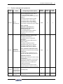
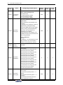
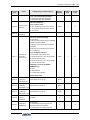
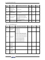
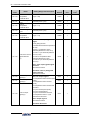
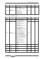
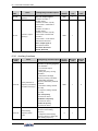
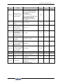
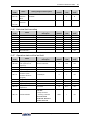
Functional Parameter Table ..............................................................................................36
6.1
System management parameter.............................................................................37
6.2
Running command selection...................................................................................41
6.3
Frequency setting ...................................................................................................42
6.4
Control command source........................................................................................43
6.5
Start and stop..........................................................................................................43
6.6
Acceleration and deceleration characteristics parameters......................................45
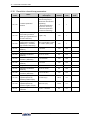
6.7
Carrier frequency ....................................................................................................46
6.8
V/F parameters and overload protection.................................................................46
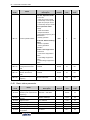
6.9
Steady running........................................................................................................47
6.10
Motor parameters..................................................................................................49
6.11
Parameter measurement and pre-excitation .........................................................49
6.12
Multifunctional input terminal ................................................................................50
6.13
Multifunctional output terminal multifunctional output terminal..............................51
6.14
Pulse input ............................................................................................................52
6.15
Pulse output..........................................................................................................52
6.16
Analog input..........................................................................................................53
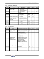
6.17
Analog input curve correction ...............................................................................53
6.18
Analog output........................................................................................................54
6.19
Analog input wire breakage detection ...................................................................55
6.20
Virtual analog input ...............................................................................................56
6.21
Hopping frequency................................................................................................57
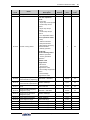
6.22
Built-in auxiliary timer............................................................................................57
6.23
Built-in auxiliary counter........................................................................................59
6.24
Auxiliary functions.................................................................................................60
6.25
Multi-stage frequency setting ................................................................................62
6.26
Simple programmable multi-stage operation ........................................................63
6.27
Swing frequency operation ...................................................................................65
6.28
Process PID (4ms control cycle)...........................................................................66
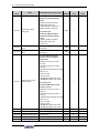
6.29
Process PID multi-stage setting ............................................................................69
6.30
Process PID sleep function...................................................................................69
6.31
Revolution setting and feedback...........................................................................70
6.32
Revolution closed-loop parameters.......................................................................72
6.33
Protection parameter ............................................................................................73
6.34
Torque control .......................................................................................................73
6.35
MODBUS fieldbus.................................................................................................74
6.36
Mapping access parameter...................................................................................75
6.37
Communication linkage synchronous control........................................................76
6.38
Expansion multifunctional input terminal...............................................................76
6.39
Expansion multifunctional output terminal.............................................................77
6.40
Zero-speed torque and position control ................................................................77
6.41
Virtual input and output .........................................................................................78
6.42
Protection function configuration parameters........................................................79
6.43
Correction parameter ............................................................................................81
6.44
Special functional parameters...............................................................................81
6.45
Other configuration parameters ............................................................................82
6.46
Historical fault recording .......................................................................................83
6.47
Operation status at the last fault ...........................................................................83
6.48
Basic status parameter .........................................................................................84
6.49
Auxiliary status parameter ....................................................................................86
6.50
MODBUS fieldbus status parameter .....................................................................87
6.51
Terminal status and variable .................................................................................87
6.52
Counter timer value...............................................................................................88
6.53
Positioning status parameter.................................................................................88
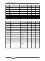
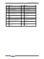
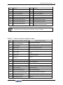
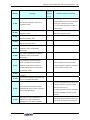
Exhibit 1 Comparison table of multifunctional terminal (DI/EDI/SDI) functions ................90
Exhibit 2 Comparison table of multifunctional output terminal (DO/EDO/SDO) ...............92
Exhibit 3
7
Monitor variable comparison table .................................................................93
Function Details .................................................................................................................95
7.1
System management (Group F0.0).........................................................................95
7.2
Running command selection (Group F0.1) ...........................................................104
7.3
Frequency setup (Group F0.2)..............................................................................106
7.4
Control command source (Group F0.3) ................................................................109
7.5
Start and stop (Group F0.4) .................................................................................. 111
7.6
Acceleration and deceleration characteristics (Group F1.0) ................................. 117
7.7
Carrier frequency (Group F1.1)............................................................................. 119
7.8
V/F parameters and overload protection (Group F1.2) .........................................120
7.9
Steady running (Group F1.4) ................................................................................122
7.10
Motor parameters (Group F2.0) ..........................................................................125
7.11
Parameter measurement and pre-excitation (Group F2.2)..................................126
7.12
Multifunctional input terminal (Group F3.0) .........................................................127
7.13
Multifunctional output terminal (Group F3.1).......................................................136
7.14
Pulse input (Group F3.2).....................................................................................139
7.15
Pulse output (Group F3.3) ..................................................................................140
7.16
Analog input (Group F4.0) ..................................................................................141
7.17
Analog input curve correction (Group F4.1) ........................................................142
7.18
Analog output (Group F4.2) ................................................................................143
7.19
Analog input wire-break detection (Group F4.3) .................................................144
7.20
Hopping frequency (Group F5.0) ........................................................................145
7.21
Built-in auxiliary timer (Group F5.1) ....................................................................146
7.22
Built-in auxiliary counter (Group F5.2) ................................................................148
7.23
Auxiliary functions (Group F5.3) .........................................................................149
7.24
Multi-stage frequency setting (Group F6.0).........................................................153
7.25
Simple programmable multi-stage operation (Group F6.1) .................................154
7.26
Swing frequency operation (Group F6.2) ............................................................158
7.27
Process PID (4ms control cycle) (Group F7.0) ...................................................161
7.28
Process PID multi-stage setting (Group F7.1) ....................................................165
7.29
Process PID sleeping function (Group F7.2).......................................................165
8
7.30
Revolution setting and feedback (Group F8.0) ...................................................166
7.31
Revolution closed-loop parameter (Group F8.1).................................................169
7.32
Protective parameters (Group F8.2) ...................................................................171
7.33
Torque control (Group F8.3)................................................................................172
7.34
MODBUS fieldbus (Group FA.0) .........................................................................173
7.35
Mapping parameter access (Group FA.1) ...........................................................173
7.36
Communication linkage synchronous control (Group FA.2) ................................175
7.37
Zero-speed torque and position control (Fb.2 group)..........................................176
7.38
Virtual input and output (group FF.0)...................................................................177
7.39
Protecting function configuration parameters (FF.1 group) .................................178
7.40
Correction parameters (FF.2 group)....................................................................178
7.41
Special functional parameters (FF.3 Group)........................................................180
7.42
Other configuration parameters (Group FF.4) .....................................................180
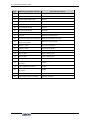
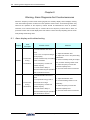
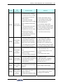
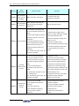
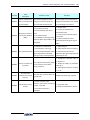
Warning, Alarm Diagnosis And Countermeasures .......................................................182
8.1
Alarm display and troubleshooting........................................................................182
8.2 Warning display and troubleshooting....................................................................189
9
Care And Maintenance ....................................................................................................193
9.1
Routine care and maintenance .............................................................................193
9.2 Inspection and displacement of the vulnerable components.................................194
9.3
9.2.1
Filter capacitor .........................................................................................194
9.2.2
Cooling fan...............................................................................................194
Storage .................................................................................................................195
9.4 Warranty ...............................................................................................................196
10
11
Description Of Communication Protocol.....................................................................197
10.1
Protocol overview ...............................................................................................197
10.2
Interface and transmission method.....................................................................197
10.3
Data structure .....................................................................................................197
10.4
Parameter configuration for frequency inverters .................................................198
10.5
Brief introduction of functions..............................................................................198
10.6
Access address summary...................................................................................199
10.7
Detailed modbus address-finding distribution .....................................................200
Optional Components....................................................................................................206
11.1
I/O expansion card introduction...........................................................................206
11.2
PG expansion card introduction .......................................................................... 211
11.3
11.4
11.5
Brief introduction to operation panel....................................................................212
11.3.1
Outside view of operation panel .............................................................212
11.3.2
Button function .......................................................................................212
Tension control expansion card...........................................................................213
11.4.1
Basic product information.......................................................................213
11.4.2
Product introduction ...............................................................................213
11.4.3
Product function .....................................................................................213
11.4.4
Technical data ........................................................................................213
Expansion card of all-in-one veneer peeling lathe...............................................214
11.5.1
11.6
Basic product information.......................................................................214
11.5.2
Product introduction ...............................................................................214
11.5.3
Product function .....................................................................................214
11.5.4
Technical data ........................................................................................214
AC/DC reactor.....................................................................................................215
11.6.1
DC reactor..............................................................................................215
11.6.2
AC input reactor .....................................................................................216
11.6.3
AC output reactor ...................................................................................217
Product Confirmation And Operation Precautions 1
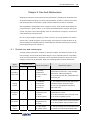
Chapter 1 Product Confirmation And Operation Precautions
1.1 Product confirmation
Check the outer packing carefully to see if there is any damage after the arrival of the goods; if there
is a label on the outer packing, please confirm the model and specification of it to see if they are in
accordance with your order. If any damage or discrepancy is found, please contact the supplier
promptly for solution.
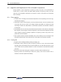
1.1.1
Precautions of unpacking inspection
Confirm the frequency inverter body and accessories carefully when unpacking, to see if there is any
damage during the transit, and if the parts and components are damaged or dropped, and if there is
the frequency inverter entity and the following accessories:
1) Operation instruction;
2) Certification;
3) Product list;
4) Other ordered accessories.
If there is any omission or damage, please contract the supplier promptly for solution.
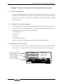
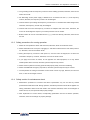
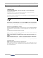
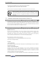
●
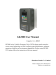
Nameplate of Frequency Inverter
On the frequency inverter, there is a nameplate marked with model, rated parameters, product
serial-number and bar code of frequency inverter. The content of nameplate is shown as below:
Model of变频器型号
frequency inverter
Rated input voltage number of phase,
额定输入电压相数、电压及频率
voltage and frequency
Rated output
capability and current
额定输出容量及电流
Product serial-number
产品序列号
TYPE:
V350-4T0022
SOURCE:
3PH 380V 50/60Hz
OUTPUT:
3.6KVA 5.5A
SERIAL No.:
XXXXXXXXXX
Bar code,
certification logos
条形码、认证标识
V350 Low-Power Closed-Loop Vector Inverter User Manual
2
Product Confirmation And Operation Precautions
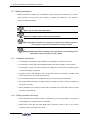
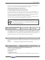
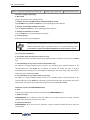
1.2 Safety precautions
Read this instruction carefully prior to installation, wiring, operation and maintenance, to ensure
proper operation of this product. "Tip", "Attention", "Danger" and "Warning" in this operation
manual are defined as follows:
“Tip”: Tips for some useful information.
“Attention”: Matter requires attention during operation.
“Warning”: Without operation according to the requirements, moderate injuries or
minor injuries of personnel and material loss may be caused.
“Danger”: Without operation according to the requirements, serious damage to the
equipment or personnel injuries may be caused.
1.2.1
Installation precautions
1. The frequency inverter shall not be installed on combustibles, in case of the risk of fire.
2. The frequency inverter shall not be installed at places with direct sunlight, in case of danger.
3. The frequency inverter of this series shall not be installed in the environment of explosive gases,
in case of the danger of explosion.
4. Frequency inverter with damage or lack of components shall not be applied; otherwise it may
cause personal injury or fire and other accidents.
5. It is not allowed to dismount or modified the frequency inverter without authorization.
6. No foreign matter is allowed to be dropped into the frequency inverter, in case of breakdown of
the frequency inverter.
7. During installation, the frequency inverter shall be installed at the place able to bear its weight;
otherwise, it may fall down.
1.2.2
Safety precautions for wiring
1. Please authorize the professional staff to conduct wiring. If the wiring operation is not proper, it
may damage to the equipment and the individuals.
2. Please start to wire after the panel digital tube of frequency inverter is out for ten minutes,
otherwise, there can be electric shock risk.
V350 Low-Power Closed-Loop Vector Inverter
User Manual
Product Confirmation And Operation Precautions 3
3. The grounding terminal of frequency inverter must be reliably grounded; otherwise, there can be
electric shock risk.
4. No alternating current power supply is allowed to be connected onto the U, V, W of frequency
inverter, otherwise, the frequency inverter can be damaged.
5. Confirm that the input voltage and frequency converter are in consistent with rated voltage value;
otherwise, the frequency inverter may be damaged.
6. Confirm that the motor and frequency converter are adaptive with each other, otherwise, the
motor can be damaged or frequency converter protection can be caused.
7. Brake resistor can not be connected onto the (+), (-) of DC bus directly; otherwise, there can be
fire risk.
1.2.3
Safety precautions for running operation
1. Please do not operate the switch with wet hand; otherwise, there can be electric shock.
2. Please install the front cover prior to plugging in, and shall not demount the cover while power is
on, otherwise, here can be electric shock.
3. During the frequency converter is with power on, even the motor is stopped, do not touch the
terminals of frequency converter, otherwise, here can be electric shock.
4. If you apply the function of restart, do not approach the load equipment, for it may restart
suddenly after alarm removed, otherwise, personal injuries may caused.
5. Please set the system as ensuring personal and property safety even when restarting.
6. Please set additional emergency stop switch, otherwise, personal injuries may be caused.
7. The temperature of cooling fin and direct current reactor can be very high, therefore, do not touch
them, in case of the danger of burns.
1.2.4
Safety caution for maintenance check
1. Maintenance operations of overhaul and device replacement only can be done by trained
professional maintenance staff. During operation, insulation protection tools shall be applied. It is
strictly prohibited to leave thrum and metal in the machine. Otherwise, there can be dangers of
electric shock, fire, and personal and property damage.
2. After replacement of control board, corresponding parameters must be set before operation,
otherwise, there can be danger of property damage.
V350 Low-Power Closed-Loop Vector Inverter User Manual
4
Product Confirmation And Operation Precautions
1.3 Knowledge on operation
1.3.1
Application knowledge of driving general motor
1. The temperature when driving general motor applied with frequency converter can be a little
higher than that of industrial frequency power. With long-term operation at low speed, the
operation life of motor can be affected due to the poorer heat dissipation effect. In this case,
special frequency converter shall be selected or lighten the motor load.
2. If when the equipment is installed with frequency converter drive, sometimes, there can be
resonance due to the natural vibration frequency of mechanical system, please consider about
applying flexible coupling and insulation rubber, or applying the function of hopping frequency of
the frequency converter, to avoid the resonance point for operation.
3. There can be larger noise when driving general motor applied with frequency converter than that
of industrial frequency power. In order to reduce the noise, the carrier frequency can be increased
properly.
1.3.2
Application knowledge of driving special motor
1. For high-speed motor, if the set frequency of frequency converter is above 120Hz, please
conduct combination test with motor, to make sure it can be operated safely.
2. For synchronous motor, there must be correspondences according to the types of motor. Please
contract the manufacturer for consultation.
3. Operation of single-phase motor is not applied with frequency converter. Even when input with
single phase, there is three-phase output, please apply with three-phase motor.
1.3.3
Ambient environment
Application shall be applied in the indoor range with environment temperature of -10 to +45℃,
humidity around 5~95% (without condensation of moisture), no dust, no direct sunlight, no corrosive
gas, no combustible gas, no oil mist, no steam, no water or floating fiber or mental particles; if there
is special requirements of clients, please contract the manufacturer for consultation.
1.3.4
Connection knowledge of peripheral equipment
1. For the protection of wirings, please configure breaker for wirings on the input side of frequency
converter. Please do not apply device with larger capacity than recommendation.
2. If it needs to switch to industrial frequency power and others, when installing electromagnetic
contactor on the output side of frequency converter, please switch after frequency converter
and motor stop running.
3. When applying with motor thermal relay, if the wiring of motor is too long, sometimes it is affected
V350 Low-Power Closed-Loop Vector Inverter
User Manual
Product Confirmation And Operation Precautions 5
with the high-frequency current flowing through capacitance distributed with wiring, current
below the set value of thermal relay may also cause trip. In this case, please lower the carrier
frequency, or apply with output filter.
4. For noise interference, connection filter, magnet ring and shielded wire can be applied as
corresponding measures.
1.3.5
Transportation and storage
1. During product handling, please capture the both sides of the bottom of the entity, rather than
the cover or parts only.
2. Please do not make the parts of plastic excessive forced, otherwise, there can be falling down
or damage.
3. When it is for temporary storage and long-term storage, pay attention to the followings:
z
Try to be packaged in the packing case of our company as the original package for
storage.
z
Long-term of storage will lead to the characteristics of electrolytic capacitor worsen,
therefore, it shall be powered on every half year at least, and with conduction time more
than half an hour, and the input voltage must be risen to the rated value gradually with
voltage regulator.
1.4
Abandon caution
1. Explosion of the electrolytic capacitor: electrolytic capacitor in the frequency converter may
cause explosion while burning.
2. Waste gas of plastic burning: harmful and toxic gas may be produces while burning the plastic
and rubber product of the frequency converter.
3. Disposal methods: please deal with the frequency converter as industrial waste.
1.5 Other cautions
1. This product shall not be applied for life support device and other application concerning
directly with human body safety, otherwise, there can be accident.
2. If serious accident or serious losses caused due to the failure of this product, please install
safety device for this product, otherwise, there can be accident.
V350 Low-Power Closed-Loop Vector Inverter User Manual
6 Product Introduction
Chapter 2 Product Introduction
2.1 Model description
V350 - 4 T 0090
Power grade
0011:1.1KW
0030:3.0KW
0075:7.5KW
0150:15 KW
0015:1.5KW
0040:4.0KW
0090:9.0KW
Power supply phase
Voltage grade
0022:2.2KW
0055:5.5KW
0110:11 KW
T: three phase
2:220V
S: single phase
4:380V
Product series
V350: Low-power closed-loop vector inverter
V560: High-performance closed-loop vector inverter
A510: Heavy-load closed-loop vector inverter
E550: Low-power universal inverter
E380: Universal inverter
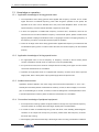
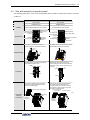
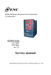
2.2 Product appearance
Appearance of Category I
Applicable for: V350-4T0030/2S0022 and below models
Operating
操作面板panel
散热器
Radiator
Port
of operating
操作面板接口
panel
Port of remote
远程操作面板接口
operating
panel
Lower
下盖 cover
Function expansion card
Upper
上壳 housing
Wiring
entrace of
扩展回路接线入口
extension
loopr
Plugboard
插板
Wiring
entrace of
主回路接线入口
main loop
Fan
风扇
Appearance of Category II
功能扩展卡
Expansion loop
扩展回路端子
terminal
Major
loop terminal
主回路端子
Applicable for: V350-4T0040 and above models
Operating
操作面板panel
Upper
上盖 cover
上壳 housing
Upper
Port
of operating panel
操作面板接口
Crystal
connector position
水晶转接头放置位
(remote operation)
(远程操作)
Lower
下壳 housing
Lower
下盖 cover
Wiring entrace of
扩展回路接线入口
extension
loopr
Wiring entrace of
控制回路接线入口
control loop
Wiring
entrace of
主回路接线入口
main loop
插板
Plugboard
Control loop terminal
控制回路端子
Major
loop terminal
主回路端子
V350 Low-Power Closed-Loop Vector Inverter User Manual
Product Introduction 7
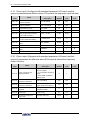
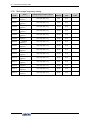
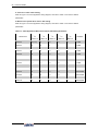
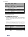
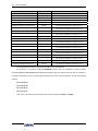
2.3 Model table
Voltage grade
Single-phase
220V
Three-phase
380V
Model
Rated capacity
(KVA)
Suitable motor
(KW)
Rated current
(A)
V350-2S0007
1.9
0.75
5.0
V350-2S0011
2.5
1.1
6.5
V350-2S0015
2.9
1.5
7.5
V350-2S0022
3.8
2.2
10.0
V350-4T0011
2.0
1.1
3.0
V350-4T0015
2.4
1.5
3.7
V350-4T0022
3.6
2.2
5.5
V350-4T0030
4.9
3.0
7.5
V350-4T0040
6.3
4.0
9.5
V350-4T0055
8.6
5.5
13.0
V350-4T0075
11.2
7.5
17.0
V350-4T0090
13.8
9.0
21
V350-4T0110
16.5
11
25
V350-4T0150
21.7
15
33
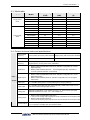
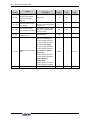
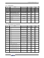
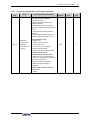
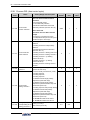
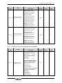
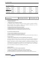
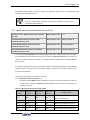
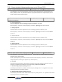
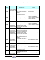
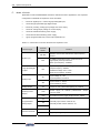
2.4 Product technical index and specifications
Input
Rated voltage,
frequency
Three phase (4T# series) 380V 50/60Hz Single phase (2S# series) 220V 50/60Hz
Output voltage
0~380 V
Output
frequency
Low-frequency running mode: 0.00~300.00Hz;
High-frequency running mode: 0.00~1000.00Hz
Digital input
y Models V350-4T0030/2S0022 and below: standard configuration of 5-circuit
digital input (DI)
y Models V350-4T0040 and above: 6-circuit digital input (DI), extensible to
16-circuit (optional extension components)
Digital output
y Models V350-4T0030/2S0022 and below: standard configuration of 1-circuit
digital output (DO)
y Models V350-4T0040 and above: standard configuration of 2-circuit digital
output (DO)
Pulse input
0 ~ 100.0KHz pulse input, to connect NPN type OC output (optional)
Pulse output
0 ~ 100.0KHz pulse NPN type OC output (optional); I PWM output mode can be
selected to extend analog output terminal.
Analog input
Standard configuration: 0-10V voltage input (AI1); 0 - 20mA current input (AI2)
Standard expansion I/O card: -10V - 10V voltage input
Analog output
y Models V350-4T0030/2S0022 and below:
1-circuit 0-10V analog output signal(can be set to 0-20VmA current output mode)
y Models V350-4T0040 and above:
2-circuit 0-10V analog output signal(can be set to 0-20VmA current output mode)
Contact output
Standard one group of AC 250V/2A normally open and closed contacts, extensible
to 1-6 groups of normally open and closed contacts.
0~220 V
Output
V350 Low-Power Closed-Loop Vector Inverter User Manual
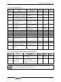
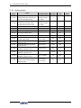
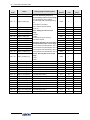
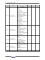
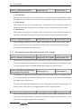
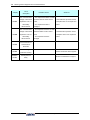
8 Product Introduction
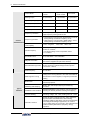
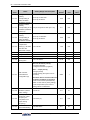
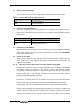
Control
Characteristics
Typical
Function
Control Mode
Closed-loop vector
control
Open-loop
vector control
V/F control
Starting torque
0 speed 200%
0 speed180%
0 speed180%
Speed adjusting range
1:1000
1:200
1:100
Steady speed precision
±0.02%
±0.2%
±0.5%
Torque control precision
±5%
±5%
--
Torque response time
≦5ms
≦25ms
--
Frequency resolution
Low-frequency running mode: 0.01Hz
High-frequency running mode:0.1Hz
Frequency precision
y Low-frequency running mode: digital setting—0.01Hz,
analog setting—maximum frequency ×0.1%
y High-frequency running mode: digital setting—0.1Hz,
analog setting—maximum frequency ×0.1%
Load capacity
110%-- long term ;150%--60s;180%--2.5s
Carrier frequency
y three-phase voltage vector composition
mode:1.5~10.0KHz;
y two-phase voltage vector composition mode:
1.5~12.5KHz
Deceleration and
acceleration time
0.01~600.00Sec. / 0.01~600.0Min.
Magnetic flux brake
Achieve rapid retarding brake of the motor by increasing
the motor's magnetic flux (30-120% allowed)
DC brake/band-type rake
DC brake/band-type brake initial frequency: 0.0 - upper
limiting frequency, brake/band-type brake injection
current 0.0 - 100.0%
Strike frequency
0.0~50.0Hz
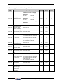
Multi-segment running
16-segment frequency/speed running, independent
setting of the running direction, time and acceleration &
deceleration of each segment; 7-segment process PID
setting
Built-in PID
Built-in PID controller, can be used independently by
external equipment
Wakening and sleeping
Built-in PID, with simple sleeping and wakening
functions.
MODBUS communication
Standard MODBUS communication protocol (optional)
allowing for flexible parameter reading and mapping.
Dynamic braking
Actuating voltage: 700 - 760V, braking ratio: 50 - 100%
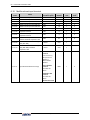
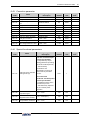
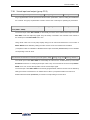
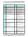
General Functions
Power-off restart, fault self-recovery, motor parameter
dynamic/static self-identification. Start enabling,
operation enabling, start delay, overcurrent suppression,
overvoltage/undervoltage suppression, V/F custom
curve, analog input curve correction, line brake detection,
textile machinery disturbance (frequency swing)
operation.
V350 Low-Power Closed-Loop Vector Inverter User Manual
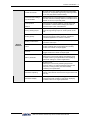
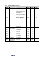
Product Introduction 9
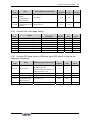
Virtual IO terminal
8-circuit one-to-one virtual output and input terminals,
allowing for complicated engineering onsite application
in an easy way without external wiring.
Communication linkage
synchronization
Easily allows for synchronized drive of multiple motors,
and free selection of linkage balance of multiple motors
based on current, torque and power.
Load dynamic
balance
Special
Function
Also allows for dynamic balance of multi-motor load
(not limited to communication linkage) and able to
achieve torque motor characteristics.
Strong starting torque
For load featuring high inertia and high static friction,
super strong starting torque for certain period can be
set.
Setting priority
Users can freely select the priority of various
frequency/revolution setting channels; suitable for
combined application for various occasions.
Setting combinations
Up to hundreds of setting combinations of frequency,
revolution and torque
Timer
3 built-in timers: 5 kinds of clock, 5 kinds of trigger
modes, multiple door access signals and working
modes, and 7 kinds of output signals.
Counter
2 built-in counters: clock margin selection, 4 kinds of
trigger modes and 7 kinds of output signal
Macro parameter
Application macro:
Allowing for conveniently setting and partially curing
multiple common group parameters and simplifying
parameter setting for common applications.
System macro:
Allowing for conveniently switching equipment’s
working mode (e.g. switching between high and low
frequency running modes), and automatically
redefining local parameters.
Parameter adjusting
Any un-stored parameter adjusted on site can be
stored or abandoned and restored to original value with
one key.
Parameter display
Allowing for automatically shielding parameters of
unused functional modules or selectively displaying
modified, stored or changed parameters.
V350 Low-Power Closed-Loop Vector Inverter User Manual
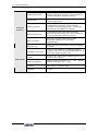
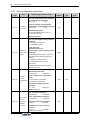
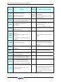
10
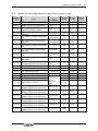
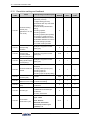
Product Introduction
Equipment abnormity
Current detected abnormity, EEPROM memory
abnormity, abnormal control unit, motor overtemperature and temperature acquisition loop fault.
Power supply
Undervoltage protection and three-phase power supply
unbalancing protection.
Running protection
Overcurrent protection, overvoltage protection, inverter
overtemperature protection, inverter overload
protection, motor overload protection, output phase
lack protection, and IGBT drive protection.
Equipment abnormity
Current detected abnormity, EEPROM memory
abnormity, abnormal control unit, motor overtemperature and temperature acquisition loop fault.
Motor connection
Motor not connected, motor’s three-phased
parameters unbalanced and parameter
misidentification.
Extension card
Detect and protect the extension card for compatibility
or conflict.
Installation environment
Indoor vertical installation, not subjecting to direct
sunshine, free of dust, corrosive and flammable gas, oil
mist, vapor and free of drips or salt.
Altitude
0-1000 m. The output current capability drops by 10%
for every rise of 1000 m.
Ambient temperature
Working ambient temperature: -10℃ - +45℃ ; storage
ambient temperature: -20℃ - +60℃
Humidity
95% below, no condensed water
Ventilation
< 6m/s2
Protection
Function
Environment
V350 Low-Power Closed-Loop Vector Inverter User Manual
Installation Of Frequency Inverter
11
Chapter 3 Installation Of Frequency Inverter
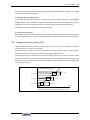
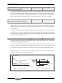
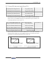
3.1 Installation of frequency inverter
This series of frequency inverters are wall-mounted frequency inverters, which should be installed
vertically. In order to be in favor of circulation and heat dissipation, please install the frequency inverter at
indoor place with good ventilation. Please refer to 1.3.3 for installation environment. If there is special
installation requirement from customer, please contact the manufacturer in advance.
y
Mounting surface
The temperature of cooling fin may rise to around 90℃, so please install the mounting surface at the place
which can stand for this temperature rise.
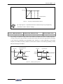
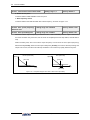
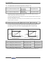
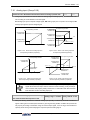
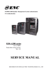
y
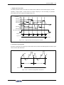
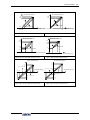
Installation space
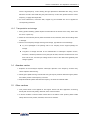
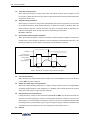
Requirements for installation spacing distance of single frequency inverter are as shown in figure 3-1.
Reserve enough space around the frequency inverter.
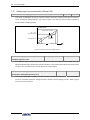
y
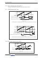
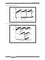
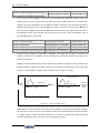
Multiple installations
If install more than 2 sets of frequency inverters in device or control cabinet, please conduct parallel
installation in principle as shown in figure 3-3. If there is no choice but vertical installation, please consider
setting partition plate as shown in figure 3-2, to ensure no influence on upper frequency inverter from lower
frequency inverter.
Fan exhaust
Align the
upper
part
对齐上部
Left and
right space
左右空间
风扇
排气
Up and down space
上下空间
A
A
D
D
C
A
A
D
A
Figure 3-1 Spacing distance for installation
B
A
B
D
Figure 3-2 Left and Right Installation Size of Two Inverters (4.0KW above)
V350 Low-Power Closed-Loop Vector Inverter User Manual
12
Installation Of Frequency Inverter
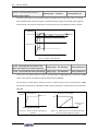
¾
¾
As shown in Figure 3-1 and 3-2: A≥50mm, B≥30mm, C≥20mm, D≥120mm
When horizontally and closely installed under 4.0KW, the ambient temperature is -10℃ 45℃.
¾
Horizontally close installation is only for 4.0KW below, and -10℃ - 45℃ environmental
temperature.
¾
For parallel installation of frequency inverters with different sizes, please carry out
installation after aligning the upper parts of all the frequency inverters, thus to be in favor
of changing cooling fan.
¾
Please don’t install frequency inverter in the environment with tattered cotton yarn and
damp dust which may cause blockage of cooling fin. If necessary to operate in such
environment, please install in the control cabinet which can keep tattered cotton yarn out.
¾
If necessary to install at the place with more than 1000m height above sea level, please
derate operation. See 2.4 product technical indexes and specifications for details.
V350 Low-Power Closed-Loop Vector Inverter User Manual
Installation Of Frequency Inverter
13
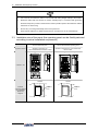
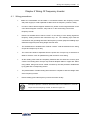
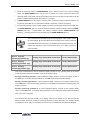
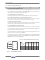
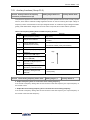
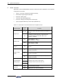
3.2 Size and assembly of operation panel
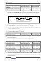
The operating panel name, mode, code and applicable device models of V350 series inverters are shown
in Table 3-1.
Name
Two-line LED small panel
Model
DPNL350EM
DPNL360EB
Code
Applicable
models
050M007033701
050M007360004
V350-4T0030/2S0022 and below models
V350-4T0040 and above models
LED
main display
LED主显示
LED 数码
LCD display
area
LED
auxiliary
LED辅显示
display
显 示 区
Unit combination
单位组合
indicator
显 示 灯
Appearance
Two-line LED standard operating panel
LED
main display
LED主显示
LED area
数码
LCD display
LED
auxiliary display
LED辅显示
显 示 区
Unit combination
单位组合
显 示 灯
indicator
功能组合
Functional
显
示 灯
combination
indicator
功 能
Function
操作区
operating
area
Shuttle
飞梭按键 key
Functional
combination
功能组合
indicator
显 示 灯
Function
功 能
operating area
操作区
Shuttle
飞梭旋钮 knob
Put fingers on the slot at front part of
the panel and then simply raise the panel
Put fingers on the slot at front part of the
panel and then simply raise the panel.
After aligning the panel with the panel slot,
press down the panel evenly.
After aligning fixed hook month at the
bottom of the panel with the clasp under the
panel base, simply press down the top of
the panel.
Disassembling
卡扣
Clasp
卡槽
Slot
卡扣
Clasp
卡槽
Slot
Installation
Clasp
卡扣
Slot
卡槽
Clasp
卡扣
Remove the operating panel and make
connection with the extension cable as
shown in following figure.
外接卡扣
Clasp
for external connection
Remove the operating panel and detach
the crystal connector and place it at
specified position to avoid loss, and then
use extension cable to make connection
as shown in following figure.
Clasp for external
Crystal connector
connection
外接卡扣
水晶转接头
连接线
connecting
wire
Prolonged
external
connection
外接卡扣
Clasp for
external
connection
连接线
connecting
wire
Clasp 外接卡扣
for
external
connection
V350 Low-Power Closed-Loop Vector Inverter User Manual
14
Installation Of Frequency Inverter
¾
¾
It is a must to use extension cable or commercial LAN cable (straight cables) in the market.
Extension cable shall not exceed 15 meters; shielding layer is connected with grounding
terminal of frequency inverter. Please select remote operation panel if the extension cable is
more than 15 meters long.
¾
Do not carry out wiring horizontally close to the power line.
¾
Panel shall be fastened on stable fixed surface or work bench so as to avoid damage.
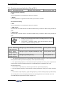
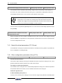
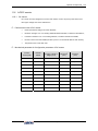
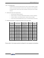
3.3 Installation size of the panel (the operating panel can be flexibly selected
according to actual installation requirement)
Name
Two-line LED small panel
Two-line LED standard operating panel
Applicable Models
Standard configuration for
V350-4T0030/2S0022 and below models
Standard configuration for V350-4T0040 and
above models
55
25
70
126
130
105
101
50
23
22
27
Installation size
51
66
46.5
30
102*52
127*67
52
安装板
Installation
board
安装 板
Installation
board
127
102
External
connection without
tray, installation
board hole
diagram
67
V350 Low-Power Closed-Loop Vector Inverter User Manual
Installation Of Frequency Inverter
15
Installation
安装板 board
17
2
9
Fixed
螺钉
with
固定
screws
5
5
9
This connection mode is not applicable
5
2
1
4
0
1
External
connection with
tray, installation
board hole
diagram
Th
rou
gh
ho
le
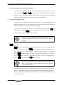
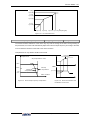
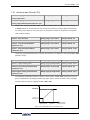
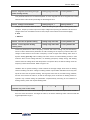
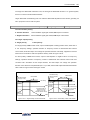
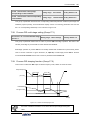
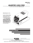
3.4 Removal of terminal cover
Removal: put fingers on the handle slot at the bottom of cover plate (the position of clasp as figure 3-7),
and forcibly lift it upward until the card clasps between cover plate and shell break away, then pull the
cover plate down can disassemble the shell. See figure 3-7
Installation: slant cover plate into about 15°, then insert the fixed stator at the top of cover plate into fixed
slot on shell. Forcibly press the cover plate down until heard a click, which means the cover plate has been
in place.
Control
loop terminal
控制回路端子
扣手位置
Fastener
position
Lower
前插板 plug
下盖板 Front
cover plate board
Main
loop terminal
主回路端子
Figure 3-7 Disassembly and installation schematic diagram of plastic cover
V350 Low-Power Closed-Loop Vector Inverter User Manual
16
Installation Of Frequency Inverter
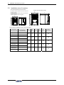
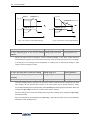
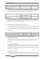
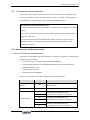
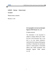
3.5 Installation size of inverters
V350-4T0030/2S0022
and
V350-4T0030/2S0022及
以below
下 机 型models
V350-4T0040及
以上
机 型 models
V350-4T0040
and
above
W1: 侧 板between
安 装 孔 之installation
间 的 距 离 holes on the side board
W1: Distance
W :board
侧板宽
度
W: Side
width
H1: 侧 板between
安装孔之
间 的 距 离 holes on the side board
H1: Distance
installation
H :
侧 板 height
高度
H: Side
board
D :前后
板 的 距front
离 and rear boards
D: Distance
between
D
D
H
H1
H
H1
W
W1
W
W1
The inverter’s installation size is shown as below:
Inverter Model
Three-phase 380V
Inverter Model
Three-phase 220V
V350-4T0011
V350-2S0007
V350-4T0015
V350-2S0011
V350-4T0022
V350-2S0015
V350-4T0030
V350-2S0022
V350-4T0040
-
V350-4T0055
-
V350-4T0075
-
V350-4T0090
-
V350-4T0110
-
V350-4T0150
-
W1
(mm)
W
(mm)
H1
(mm)
H
(mm)
D
(mm)
Screw
specification
87
97
152
162
130
M4
95
105
190
200
145
M4
121
135
234
248
175
M4
146
160
261
275
179
M5
169
180
290
305
179
M5
V350 Low-Power Closed-Loop Vector Inverter User Manual
Wiring Of Frequency Inverter
17
Chapter 4 Wiring Of Frequency Inverter
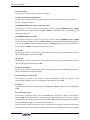
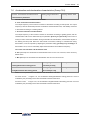
4.1 Wiring precautions
•
Make sure intermediate circuit breaker is connected between the frequency inverter
and power supply to avoid expanded accident when the frequency inverter is faulty.
•
In order to reduce electromagnetic interference, please connect surge absorber on the
coil of electromagnetic contactor, relay and etc. in the surrounding circuit of the
frequency inverter.
•
Please use shielded wire of above 0.3mm² for the wiring of such analog signals as
frequency setting terminal and instrument loop, etc. The shielding layer shall be
connected on the grounding terminal of the frequency inverter (keep the shielding layer
earthed at single end) with wiring length less than 30m.
•
The stranded wire or shielded wire of above 0.75mm² shall be selected for the wiring
of input and output loop of relay.
•
The control wire shall be separated from the power line of major loop; it shall be at a
distance of above 10cm for parallel wiring and vertical for cross wiring.
•
All the leading wires shall be completely fastened with the terminal to ensure good
contact. The leading wires of major loop shall be adopted cables or copper bar. When
using cables, wiring must not be carried out until they are cold pressed or welded well
by lug plate with corresponding section.
•
The pressurization of all the leading wires shall be in compliance with the voltage class
of the frequency inverter.
•
Please reliably ground the frequency inverter and motor locally.
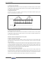
Absorption capacitor or other RC absorbers shall not be installed at U, V and W
output end of the frequency inverter, as shown in figure 4-1.
V350 Low-Power Closed-Loop Vector Inverter User Manual
18 Wiring Of Frequency Inverter
Motor
电动机
U
Inverter
变频器
M
V
W
RC
absorber
阻容吸收装置
Figure 4-1 The ketch of forbidding connecting a RC absorber at the output terminal
4.2 Connection of optional fittings and frequency inverter
•
Power supply
The power supply shall be in accordance with the specification of input power supply
designated by this operating manual.
•
Air switch
1)When the frequency inverter is maintained or not in use for a long time, the air
switch will separate the frequency inverter from the power supply;
2)When the input side of the frequency inverter has failures like short circuit, the air
switch can protect.
•
AC input reactor
When the interaction of higher harmonic between the frequency inverter and power
supply can not meet the requirements after serious wave form distortion of power
grid or the frequency inverter is equipped with DC reactor, the AC input reactor can
be added. The AC input reactor can improve the power factors at input side of the
inverter and reduce the influence caused by unbalanced voltage of three-phase
power supply.
•
Filter at input side
EMI filter can be selected to restrict the high-frequency noise interference from the
power cord of the frequency inverter.
•
Contactor
It can cut off the power supply when the system protective function acts to prevent
failure expanding.
•
DC reactor:
In order to defend the influence of power supply to frequency inverter, protect the
inverter and restrict higher harmonic, DC reactor shall be equipped under the
following conditions:
V350 Low-Power Closed-Loop Vector Inverter
User Manual
Wiring Of Frequency Inverter
19
1)When the power supply of frequency inverter has switch LBMJ on the node or with
silicon controlled phase control load, the voltage jump of the grid resulted from
reactive transient caused by capacitor switching and harmonic and grid wave form
gap caused by phase control load may damage the input rectifying circuit of the
frequency inverter.
2)When the three-phase power supply of the frequency inverter is unbalanced;
3)When the power factors at the input end of the frequency inverter are required to
improve.
•
Filter at output side
EMI filter can be selected to restrict the interference noise generated at the output side
of the inverter and wire leakage current.
•
AC output reactor
When the wiring from the frequency inverter to the motor is longer (exceeding 20m), it
can restrict radio interference and leakage current.
•
Braking resistor
Improve the braking capacity of frequency inverter to avoid overvoltage failure when
slowing down
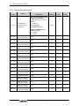
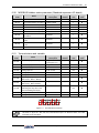
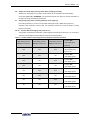
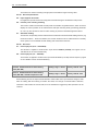
The specification of recommended electric appliances is as follows:
Model of
frequency inverter
Adaptive
motor
(KW)
Wire gauge
(major loop)
(mm2)
Air circuit
breaker
(A)
Electromagnetic
contactor
(A)
V350-2S0007
0.75
1.5
10
9
V350-2S0011
1.1
2.5
16
12
V350-2S0015
1.5
4
20
16
V350-2S0022
2.2
6
32
22
V350-4T0011
1.1
1.5
16
12
V350-4T0015
1.5
2.5
16
12
V350-4T0022
2.2
4
16
12
V350-4T0030
3.0
4
20
16
V350-4T0040
4.0
4
25
16
V350-4T0055
5.5
6
32
22
V350-4T0075
7.5
6
40
32
V350-4T0090
9.0
10
50
32
V350-4T0110
11
10
63
32
V350-4T0150
15
10
63
38
V350 Low-Power Closed-Loop Vector Inverter User Manual
20 Wiring Of Frequency Inverter
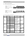
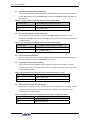
4.3 Wiring of control terminals
4.3.1 Wiring of standard terminals of control panel
CON4
Category I: CON3 and CON4
CON3
DI2 DI3
DI1
DI4
DI5 24V CM
terminals
TC
Applicable to: V350-4T0030/2S0022
TB
TA
AI1
AI2
AO1 VS GND DO1
CM
and below models
CON1
Category II: CON1 and CON2
CON2
terminals
Applicable to: V350-4T0040 and
TA
DI1
TB
TC
DI2
DO1 24V AI1 AO1
DI3 DI5
DI4
DI6
DO
VS
CM AI2 AO2 GND
above models
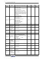
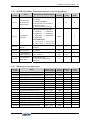
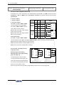
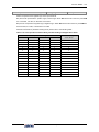
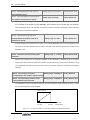
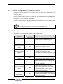
4.3.2
Function description of control terminal
Type
Control
terminal
Label of
terminal
Name
DI1-CM
Multifunctional
output terminal DI1
DI2-CM
Multifunctional
output terminal DI2
DI3-CM
Multifunctional
output terminal DI3
DI4-CM
Multifunctional
output terminal DI4
DI5-CM
Multifunctional
output terminal DI5
DI6-CM
Multifunctional
output terminal DI6
CM
Operating
status output
DO1-CM
Multifunctional
output terminal DO1
DO2-CM
Multifunctional
output terminal DO2
TA
TB
TC
Power supply
Input/output
terminal common
port
Multifunctional relay
output RO1
TA-TB normally
closed
TA-TC normally
open
CM
+24V power supply
reference place
24V
+24V power supply
Function description of
terminals
Specification
6-circuit programmable
switching value input
terminal, allowing for
selection of 98 kinds of
operational control
commands via
programming offunction
codes in F3.0 group. See
Comparison Table of
Multifunctional Output
Terminal Functions for
details (page P67).
2-circuit programmable
open-circuit collector
output and 1-circuit
programmable relay
output terminal; 63 kinds
of operating status output
can be selected by the
function code in F3.1
group by programming.
See Comparison Table for
Variables of
Multifunctional Output
Terminal for detail
(page 68).
Power supply of switching
value terminal
V350 Low-Power Closed-Loop Vector Inverter
Optical coupler
isolation input:
24Vdc/5mA
Maximum load
current: 150mA,
highest
withstand
voltage: 24V
Contact
capacity:
AC 250V/2A
Maximum
output current:
100mA
User Manual
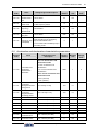
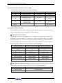
Wiring Of Frequency Inverter
Label of
terminal
Type
AI1-GND
Analog input AI1
AI2-GND
Analog input AI2
AO1-GND
Multifunctional
analog outputAO1
AO2-GND
Multifunctional
analog outputAO2
Analog input
Analog output
GND
Common terminal of
analog signal
Power supply
VS-GND
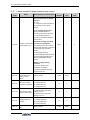
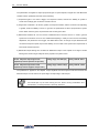
4.3.3
Function description of
terminals
Name
+10V/5V power
supply
21
Specification
Select input voltage range,
polarity and other
functions with function
code in F4 group.
Input voltage:
0~10V,
Input current:
0~20mA
The programmable
voltage/current signal
output terminal has 45
kinds of monitoring status
to be selected by
programming. See
Comparison Table for
Monitor Variables for
details. For JP1,
current/voltage output is
selected (see DIP Switch
Jumper Selection in 4.3.3
for detail)
Current output:
0~20mA
Voltage output:
0~10V
Provide externally
+10V/10mA power supply
or +5V/50mA power
supply.
JP3 (see DIP
Switch Jumper
Selection in
4.3.3 for detail)
selection
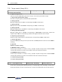
Description of dial switch on the control panel
1.There are two shifts for one dial switch.
Applicable model: V350-4T0030/2S0022 and
below models
JP3
V
A
Shift V: Indicating that AO terminal externally
拨码
Dial
outputs 0~10V voltage signal
开关
switch
Shift A: indicating that AO terminal provides
externally 0~20mA current signal.
2.There 3 shifts for three dial switches.
Applicable mode: V350-4T0040 and above
models.
JP1
Shift VO1: Indicating that AO1 terminal outputs
voltage signal.
Shift OFF: Indicating that AO1 terminal is at
拨码
Dial
开关
switch
vacant state.
Shift CO1: Indicating that AO1 outputs current
signal.
V350 Low-Power Closed-Loop Vector Inverter User Manual
VO1 VO2 5V
OFF OFF OFF
CO1 CO2 10V
22 Wiring Of Frequency Inverter
JP2
Shift VO2: Indicating that AO2 terminal outputs voltage signal.
Shift OFF: Indicating that AO2 terminal is at vacant state.
Shift CO1: Indicating that AO2 outputs current signal.
JP3
Shift 5 V: Indicating that VS terminal provides externally 5V voltage signal.
Shift OFF: Indicating that VS terminal is at vacant state.
Shift 10V: Indicating that VS terminal provides externally 10V voltage signal.
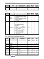
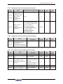
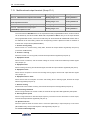
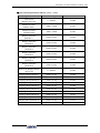
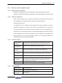
4.4 Wiring of major loop terminal
4.4.1
Terminal Functions
Symbol
Function description
Symbol
P+
DC side voltage positive terminal
P
Function description
DC electric reactor can be
connected between P+ and
PB.
DC side voltage negative
DC braking resistance can
terminal,
P-
Bus voltage input terminal of DC
PB
be connected between P+
and PB.
braking unit can be connected
between P+ and P-.
R、S、T
E
Connect three-phase AC power
supply of grid
Earthing terminal
U、V、W
--
V350 Low-Power Closed-Loop Vector Inverter
Connect three-phase AC
motor
--
User Manual
Wiring Of Frequency Inverter
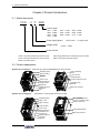
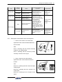
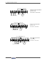
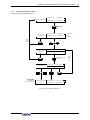
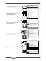
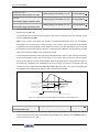
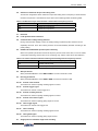
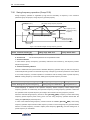
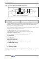
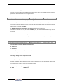
4.4.2
Main loop terminal diagram
Energy consumption
braking resistor
能耗制动电阻
L1
L2
空
N
P+
U
V
W
PB
E
Category I main loop terminal
Applicable model:
V350-2S0007~V350-2S0011
大地
Ground
电动机
Motor
单相电源输入
Single-phase
mains input
Energy consumption
braking resistor
能耗制动电阻
L1
L2
N
空
P+
E
U
V
W
PB
Category II main loop terminal
Applicable model:
V350-2S0015~V350-2S0022
大地
Ground
Motor
电动机
Single-phase
mains input
单相电源输入
能耗制动电阻
Energy consumption
braking resistor
R
S
T
P+
U
V
W
PB
E
Category III main loop terminal
Applicable model:
V350-4T0011~V350-4T0015
大地
Ground
三相电源输入
Three-phase
power supply
电动机
Motor
V350 Low-Power Closed-Loop Vector Inverter User Manual
23
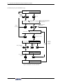
24 Wiring Of Frequency Inverter
Energy能耗制动电阻
consumption braking resistor
R
S
T
P+
E
U
V
W
Category IV main loop terminal
PB
Applicable model:
V350-4T0022~V350-4T0030
大地
Ground
电动机
Motor
三相电源输入
Three-phase
power supply
Energy consumption
braking resistor
能耗制动电阻
P+
R
S
T
U
V
W
PB
Category V main loop terminal:
E
Applicable model:
V350-4T0040~V350-4T0055
大地
Ground
电动机
Motor
三相电源输入
Three-phase
power supply
Energy consumption
braking resistor
能耗制动电阻
P+
P-
R
S
T
E
U
V
W
PB
Category Ⅵ main loop terminal:
Applicable model:
V350-4T0075~V350-4T0150
大地
Ground
三相电源输入
Three-phase
power supply
电动机
Motor
V350 Low-Power Closed-Loop Vector Inverter
User Manual
Wiring Of Frequency Inverter
25
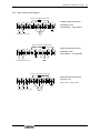
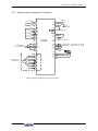
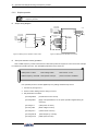
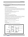
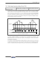
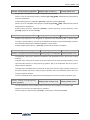
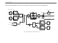
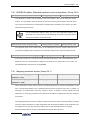
4.5 Wiring for basic operation of inverters
R
U
Motor
电动机
S
V
M
T
W
DI1
TA
DI2
TB
DI3
TC
E
接大地
Grounding
可编程输出
Programmable
output
DI4
P+
DI5
P-
DI6
PB
CM
E
VS
0-10Vfrequency
频率设定
0-10V
0-20mA
频率设定
0-20mA
frequency
AI1
AI2
GND
E
V350
24V
Connected
to
braking
外接制动电阻
resistor
辅助直流电源
Auxiliary
power supply
CM
0-10V
)/电流表(0-20mA
)
电压表(
Volt gauge
(0-10V)/ammeter
(0-20mA)
电压表(
0-10V
)/电流表(0-20mA
)
Volt gauge
(0-10V)/ammeter
(0-20mA)
AO1
AO2
GND
E
Open collector
output
开路集电极输出
DO1
PG扩展卡(选配)
+12V
GD
A+
PG expansion
card (optional)
PG
DO2
CM
E
AB+
BZ+
ZE
Figure 4-2 Basic Wiring Diagram of V350 Series Inverters
V350 Low-Power Closed-Loop Vector Inverter User Manual
26
Operation And Simple Running Of Frequency Inverter
Chapter 5
Operation And Simple Running Of Frequency Inverter
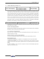
5.1 Basic function of the panel
The panel of the frequency inverter mainly has two functions apart of basic starting and stopping
control: monitoring of parameters for operating status and query and modification of internal
parameters. Accordingly, the operation panel is divided into two operating modes: monitoring
mode and parameter modification/query mode.
At the beginning of energizing, the main display column presets “sunfr” static display characters
and shifts out “sunfr” characters from right to left and recovers normal display about 3 seconds
later. At the same time, the auxiliary display column displays the serial number of the frequency
inverter statically such as “V-350” and displays the model information of the frequency inverter
except “T, S” 3 seconds later such as “4.0037” and displays normally 3 seconds later. At this time,
the operating parameters displayed in the operation panel are determined by the internal
parameters of the frequency inverter [F0.0.12], [F0.0.13]. The operation panel will return normal
monitoring mode at any status if there is no keying operation within 1 minute. (See Chapter 3 for
the appearance of the operation panel).
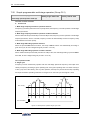
5.1.1
Panel description
LED area
数码
LCD display
显 示 区
单位组合
Unit combination indicator
LED
main display
LED主显示
LED
auxiliary
LED辅显示
display
显 示 灯
能
Function operating功area
操作区
功能组合
Functional
显 示 灯
combination
indicator
LCD LED
display
数码
area
显 示
区
Unit combination
单位组合
显 示 灯
indicator
功 能
Function
operating操作区
area
LED main
LED主显示
display
LED auxiliary
LED辅显示
飞梭按键
Shuttle
display
key
功能组合
Functional
combination
显 示 灯
indicator
飞梭旋钮 knob
Shuttle
Figure 4-1-A Two-Line LED Small Panel Standard
Figure 4-1-B Two-Line LED Standard Operating Panel
configuration for V350-4T0030/2S0022 and below models
Standard Configuration for V350-4T0040 and above models
V350 Low-Power Closed-Loop Vector Inverter User Manual
Operation And Simple Running Of Frequency Inverter
27
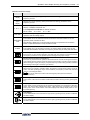
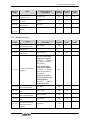
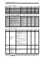
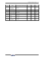
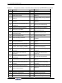
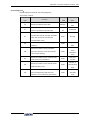
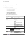
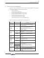
Table 5-1 Functions of keys
Item
Functions
Main digital
display
Display the current operating status parameters and setting parameters of the
frequency inverter.
Auxiliary
digital
display
Display the current operating status parameters and setting parameters of the
frequency inverter
A, Hz, V, %
FWD, REV
PANEL/REM
OTE
A, HZ, V displays the corresponding measurement unit of the data of the main digital
display. % displays compound unit
The compound unit indicator is defined as follows:
Hz+A = RPM; V+% = Sec. ;A + V = Min
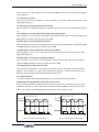
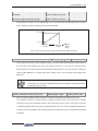
Indicator for operating status, its flicker shows the frequency inverter is in F/R
operation and has voltage output.
The indicator is off: the external terminal command is valid; the indicator is on: the
operation panel command is valid;
the indicator is flashing: the communication interface (or expanded communication
board or expanded function board) command is valid.
Alarm indicator:
ALARM
The indicator is on: the frequency inverter is in warning status. It shall check up and
eliminate abnormalities; otherwise, the frequency inverter may be faulty and shut down.
Forward operation command key
Press this key to send forward operation command when the operation command channel of
the frequency inverter is set as operation panel control ([F0.3.33] or [F0.3.34]=0)
Reverse/inching operation command key
Press this key to send reverse operation command when the reverse function ([FF.4.42=# # #
0]) is selected and the operation command channel of the frequency inverter is set as operation
panel control ([F0.3.33] or [F0.3.34]=0); and press this key to send inching operation command
when inching function ([FF.4.42=# # # 1]) is selected.
Stop/reset key
When this key is pressed in operating status, the frequency inverter will shut down as per set
mode; and when pressing this key in fault conditions, the frequency inverter will reset and
return to normal stopped status.
Keys can be locked or functions can be changed by users (refer to Functional
Parameter F0.011).
Return key
At any status, it will return to the status of last level till normal monitoring mode by pressing this
key.
Mode key
Switch display function parameter set and monitoring parameter set in parameter modification
status. The corresponding “EROM stored value”, “value at this time of energizing” and “panel
backup value” of the current function code will be displayed at auxiliary display column in turn
by pressing this key.
Left shift key
The modified data bit can be selected from right to left by pressing this key and the modified bit
has flicker display.
Right shift key
The modified data bit can be selected from left to right by pressing this key and the modified bit
has flicker display.
V350 Low-Power Closed-Loop Vector Inverter User Manual
28
Operation And Simple Running Of Frequency Inverter
Item
Functions
Data modification key
Used to mofidy function code or parameter.
If digital setting mode is set currently, the digital setting value can be modified directly by using
this key in normal monitoring mode.
Local, terminal and communication control function switch key
The keyboard control, external terminal control and communication control functinos can be
swithced with each other through setting [F0.0.11]=##1## (the switch status is not stored and
lost after power down).
Shuttle selection key
Adjust data after addition in clockwise rotation and adjust data after subtraction in
counterclockwise rotation. When [F0.0.25]=3, select panel shuttle setting.
Ok key
Confirm the current status and parameters (the parameters are stored in the internal memory)
and enter into next-level function menu.
V350 Low-Power Closed-Loop Vector Inverter User Manual
Operation And Simple Running Of Frequency Inverter
29
5.2 Basic functions and operating methods of panel
5.2.1
Basic functions of panel
The operation panel also has the following special functions aside from such basic functions as
forward operation, reverse operation, inching operation, shut down, fault reset, parameter
modifycation and inquiry and operating status parameter monitoring, etc.
Parameter copy and read/backup (parameter upload)
This operation panel allows for copying the internal parameters of the frequency inverter to the
operation panel (only the internal parameters opened to users) and storing permanently.
Therefore, users can backup their typical setting parameters to the operation panel for emergency.
The backup parameters in the operation panel do not influence the operation of the frequency
inverter and can be checked and modified separately.
When [F0.0.08]=####1, the keyboard will begin to read the internal parameters of the frequency
inverter and the operation panel will display the process of reading parameters in real time. After
the completion of parameter backup, the display mode will recover to normal monitoring
automatically. During parameter backup, the operation can be stopped at any time by pressing
key and the display will switch to normal monitoring mode.If alarm information is occurred,
please refer to Chapter 8.
Parameter copy/write in (parameter download)
This operation panel allows for copying the backup parameters to the internal memory of the
frequency inverter (only the internal parameters opened to users) and users can write in their
typical setting parameters backed up in the operation panel into the frequency inverter at one
time without separate modification.
When the frequency inverter set F0.0.08 as # # 1 2 or # # 1 3 in stopped mode, the keyboard will
begin to copy the backup parameters to frequency inverter and the operation panel will display
the process in real time. After the completion of copying, the display mode will recover to normal
monitoring automatically.
During parameter copying, the operation can be stopped at any time to abandon the copied
parameters by pressing
key and the display mode will switch to normal monitoring
mode. If alarm information is occurred, please refer to Chapter 8.
Check and modification of internal parameters
In normal monitoring mode, the internal parameters of the frequency inverter can be checked
and modified as per general methods by pressing
key.
V350 Low-Power Closed-Loop Vector Inverter User Manual
30
Operation And Simple Running Of Frequency Inverter
Check and modification of panel backup parameters
In normal monitoring mode, the backup parameters in the operation panel can be checked and
modified by pressing
and
key simultaneously (double key compound use) and the
high-order code “F” will display flickeringly when function code is displayed. The modification
methods of backup parameters are the same as that of internal parameters.
Locking and unlocking of panel
1) Locking: part of or all the keying functions of the panel can be locked through setting the
application parameter F0.0.11. If the parameter is set as panel locking mode, the panel will be
locked immediately after the frequency inverter is energized.
2) Unlocking: the panel will be unlocked for 5 minutes temporarily by pressing
maintaining and pressing
and
twice in order within 5 seconds and it will automatically
recover to locking if there’s no keying within 5 minutes.
To unlock the panel thoroughly, the panel locking parameter [F0.0.11]
should be modified into “unlocked” status during the temporary unlock of
the panel.
Key function
key function is limited by the application parameter F0.0.11. In function enabling and
“normal monitoring mode”, press
order “operation panel
key to switch the operation command channel in
local terminal
communication interface
operation
panel”.
indicator displays the selected command channel which will be valid by
pressing
within 3 seconds. It will abandon the switch and return to original status by
pressing
or without pressing
within 3 seconds.
When switching command channel, if the original setting is “operation
panel” or “local terminal”, the “communication interface” will be defaulted
as local MODBUS field bus.
The operation command channel switched by this function is not stored permanently. It will
recover to original setting after the frequency inverter is power down and restarted. Relevant
application parameters of the frequency inverter should be modified to permanently change
the command channel.
V350 Low-Power Closed-Loop Vector Inverter User Manual
Operation And Simple Running Of Frequency Inverter
5.2.2
Operating methods of panel
1) Query for status parameters (e.g.)
frequency
主显示:50.00Output
输出频率
Main display: 50.00
常态监控模式
Normal monitoring mode
辅显示:2.3
输出电流
Auxiliary display: 2.3
Output current
(Click twice)
(单击2次)
Query for status
状态参数查询
parameters
code
主显示:d0.0.00Monitoring
监控代码
Main display: d0.0.00
frequency
辅显示:50.00 Output
输出频率
Auxiliary display: 50.00
Select queried
status
parameters
Return
normal
control
返
回
常
态
控
制
Query for status
状态参数查询
parameters
code
主显示: d0.0.04Function
功能代码
Main display: d0.0.04
辅显示: 380
Auxiliary display: 380
输出电压
Output voltage
确定查询
状态参数
Confirm query for status
parameters
参数查询
Parameter inquiry
Return
the
last
level
voltage
主显示: 380Output
输出电压
Main display: 380
辅显示: 2.3
输出电流
Auxiliary display: 2.3 Output current
进入参数
修改模式
(参见下节)
Enter into parameter
modification mode
(refer to the next section)
Parameter modification
参数修改模式
mode
Main display: F0.0.01
Function code
Auxiliary display: 2.3
Parameter data
Figure 5-2 Query for status parameters
V350 Low-Power Closed-Loop Vector Inverter User Manual
31
32
Operation And Simple Running Of Frequency Inverter
2) Parameter query and modification (e.g.)
Main
display: 50.00 Output
frequency
主显示:50.00
输出频率
Normal monitoring
Auxiliary display: 2.3 Output current
Modification/
备份参数
query for
修改/查询
backup
parameters
(Click once)
(单击1次)
Parameter
inquiry
参数查询
Main
display: F0.0.00 Function code
主显示:F0.0.00功能代码
Auxiliary
display: 0000 Parameter
data
辅显示:0000
参数数据
Note: The function code character “F”
注:修改/查询备份参数时
will
flicker when modifying/querying
backup
parameters.
功能代码字符“F”闪烁
Select queried/modified
选择被
parameter items
Abandon放
查询/修改参数项
弃
modification
修
改
Parameter
inquiry
参数查询
Main display: F0.0.14
Function code
Auxiliary display: d0.00 Parameter data
确定查询
状态参数
Confirm query for status
Parameter inquiry
Main display: d0.00
Parameter data
Auxiliary display: 2.3 Output current
See
the indication
具体功能
for
detailed
详见标注
functions
Modify parameters as
needed
根据需要
修改参数
Parameter modification
Main display: d0.07
Parameter data
Auxiliary display: 2.3 Output current
Abandon
modification
放
弃
修
改
Continue to
继 other
modify
parameters
续
or return
修
改
其
它
参
数
或
返
回
Store the modified
parameters
存储修改
过的参数
Parameter storage
Main display: F0.0.14
Function code
Auxiliary display: d0.07 Parameter data
Figure 5-3 Parameter check and modification
V350 Low-Power Closed-Loop Vector Inverter User Manual
Operation And Simple Running Of Frequency Inverter
33
Remark: in this status, the auxiliary display column will display the following in turn by
pressing
key repeatedly. Default auxiliary monitoring parameters (original state)
EROM regional numerical value
parameter values at initial energizing
backup
parameters in operation panel, the numerical value will flicker when “EROM regional numerical
value”, “parameter values at initial energizing” and “backup parameters in operation panel” are
displayed.
5.3
Simple running of frequency inverter
5.3.1
Initial settings
●
Selection of control mode
V350 frequency inverter has three control modes: vector control without PG, vector control with
PG and V/F control. The operation control mode is selected by the application parameter
F0.0.09.
Mode 0: vector control without PG, i.e. vector control without velocity sensor, also called open
loop vector control. It is applicable to the place where encoder is not installed, has higher
requirement to starting torque and speed control precision and the normal V/F control mode can
not satisfied.
Mode 1: vector control with PG, i.e. vector control with velocity sensor, also called closed loop
vector control. It is applicable to the place where faster response of torque and higher control
precision is required.
Mode 2: V/F control mode. Except normal V/F control application, it can also be applied to the
place where the frequency inverter drives more than one motor.
The control modes of frequency inverter vary from the type and control requirements of motor
and set by parameter F0.0.09=####. For instance, the field where three-phase asynchronous
motor is used can be selected through setting F0.0.09=###0 and the field where the control
precision is highly required with velocity sensor can be set to F0.0.09=##1# speed closed loop
vector control mode.
●
Selection of frequency input channel (F0.2.25)
V350 frequency inverter has 29 frequency setting modes for each of the channel.
●
Operation command input channel [F0.3.33]
V350 Low-Power Closed-Loop Vector Inverter User Manual
34
Operation And Simple Running Of Frequency Inverter
5.3.2
Simple operation
It is absolutely forbidden to connect the power cord to the output U, V, W of the
frequency inverter.
Simple wiring diagram
three三
phase
相
power
电
supply
源
three三
phase
相
power
电
supply
源
three-phase
breakermode
三相断路器
×
×
×
R
S
T
电动机
motor
U
V
three-phase
breakermode
三相断路器
PG
expansion card
PG扩展卡(选配)
(match)
+12V
GD
M
W
E
motor
U
V
W
E
R
S
T
电动机
M
grounding
接大地
V350
A+
PG
AB+
BZ+
grounding
接大地
ZE
Figure 5-3 Wiring for the operation of SVC mode
Figure 5-4 Wiring for the operation of VC mode
SVC (non-inductive vector) operation
Take 7.5KW frequency inverter which drives 7.5KW three-phase AC asynchronous motor as the example
to indicate the operation process. The nameplate parameters of the motor are:
Rated
power: 7.5KW
rated
voltage: 380V
额定功率:7.5KW
额定电压:380V
Rated
frequency: 50.00HZ rated
speed: 1440rpm
额定频率:50.00Hz
额定转速:1440rpm
rated
current: 15.4A
额定电流:15.4A
pulse
of encoder: 1000PPR
编码器的脉冲数:1000PPR
Use operation panel to conduct digital frequency setting and start-stop control.
1.Connect as per Figure 5-3;
2.Power on after making sure the wiring is correct;
3.Set parameters as follows:
[F0.0.09]=0000
(noninductive vector control)
[F0.0.00]=0001
(apply macroparameters, set as panel operation digital setting for
[F2.0.00]=7.5
(rated power of motor)
[F2.0.01]=380
(rated voltage of motor)
[F2.0.02]=15.4
(rated current of motor)
shortcut))
[F2.0.03]=50.00
(rated frequency of motor)
[F2.0.04]=1440
(rated speed of motor)
V350 Low-Power Closed-Loop Vector Inverter User Manual
Operation And Simple Running Of Frequency Inverter
4.Press
key to start frequency inverter. If the name plate parameters (F2.0.00 ~
F2.0.04) of the motor are modified in ③, the primary static parameter identification will be
started automatically, the frequency inverter will output 0 frequency and the auxiliary
display column will display the current output current (not limited by F0.0.13 at this time).
When the display current is stable as 0.0, the automatic learning is finished and operation
is started;
5.Press
key to increase set frequency, where the output frequency of the frequency
inverter will be increased and the speed of motor will accelerate;
6.Observe the operation of motor, if there are abnormalities, stop it immediately and power
off and re-operate it after finding out the causes;
7.Press Data Modification key to reduce set frequency;
8.Press
key to stop operation and cut off the power supply.
VC (inductive vector) operation
The following parameters also need to be set except the above set parameters required by
SVC operation. The wiring diagram is as shown in figure 5-4.
[F0.0.09]=0010
[F8.0.04]=0
(inductive vector control)
(speed feedback channel)
[F8.0.05]=1000
(pulse of encoder per revolution)
[F8.0.06]
If F/R periodic vibration is occurred in starting, this parameter shall be
set as 1 (or exchange the wiring of A, B pulse); other operations are
the same as that of SVC operation.
If the motor is completely empty-load, slight oscillation may occur
sometimes in the operation under high carrier frequency. At this time,
please reduce the setting value of the carrier frequency. (Parameter
[F1.1.13 ]).
V350 Low-Power Closed-Loop Vector Inverter User Manual
35
36
Functional Parameter Table
Chapter 6 Functional Parameter Table
Note:
"×": indicates that the set value of the parameter cannot be changed when the inverter is running.
"☆": indicates the parameter is relevant with the model of the inverter.
"R": indicates the parameter is just for reading and cannot be changed;
"R/I": indicates the parameter is just for reading and cannot be changed, but can be cleared by
initialization.
"—": indicates the parameter is relevant with the type or status of connected accessories.
Variables: (H)-hexadecimal number; only bitwise data change is permitted (carry bit is not allowed),
and the upper and lower limit for bitwise change.
V350 Low-Power Closed-Loop Vector Inverter User Manual
Functional Parameter Table
37
6.1 System management parameter
Function
Code
F0.0.00
Name
Macro
parameter (H)
Setting Range and Description
The unit: Application macro (0~F)
0: void (customized setting)
1: setting of panel operation digit (factory
default)
2: setting of panel operation shuttle
3: Two-line control 1 (AT1 setting)
4: Two-line control 2 (AT1 setting)
5: Three-line control 1 (AT1 setting)
6: Tool device spindle drive (AT1 setting)
Factory
Default
Minimum
Unit
Change
Limit
0000
1
×
0001
1
Tens: reserved
Hundreds: dedicated macro
Kilobit: system macro (0~F)
0: standard operation
1: void (standard mode by default)
2. high-frequency output (0.0 ~
1000.0Hz)
The unit: parameter display mode
0: Display all parameters
1: Display effective configuration
parameters
2: Display parameters different from
factory default
3: Display modified and stored
parameters after power-on this time
4: Display modified and un-stored
parameters after power-on this time
F0.0.01
Parameter
display and
modification (H)
Tens: parameter modification mode
0: Effective and permanently stored after
modification
1: Effective after modification but not
stored, and getting lost after power-off
Hundreds: Reserved
Kilobit: batch restoring and batch saving
of parameters
2: Giving up modification of all unsaved
parameters (restore to original value)
5: Batch saving of all modified and
unsaved parameters
9: Restoring all parameters to initial
values at the time of power-on this time.
F0.0.02
Modification
key for macro
call parameters
(system macro)
0~65535(1580)
0
1
×
F0.0.03
LCD language
selection
0: Chinese
1: Reserved
0
1
-
V350 Low-Power Closed-Loop Vector Inverter User Manual
38
Functional Parameter Table
Function
Code
Name
Setting Range and Description
The unit: contrast
F0.0.04
LCD display
setting (H)
Factory
Default
Minimum
Unit
Change
Limit
0023
1
-
0000
1
0~7
Tens: normal display mode
0: Steady mode
1: Single parameter display
2: Dual parameter display
3: Three parameter display
The unit: parameter modification
F0.0.05
Parameter
locking (H)
permission
0: All parameters are permitted to be
modified
1: Except for this parameter, frequency
digital setting, PID digital setting,
revolution digital setting, torque digital
setting, locking password parameter
(F0.0.06), other parameters are
forbidden to be modified.
2: All parameters are forbidden to be
modified except for this parameter and
the locking password.
Tens: Coded lock
0: Void
1: Effective – once the password is set,
this parameter cannot be modified
unless correct password is entered.
F0.0.06
F0.0.07
F0.0.08
Parameter
locking
password
0~65535
0
1
Parameter
initialization
0: No action
1: Parameters of F0~F9 groups are
restored to the factory default.
2: Parameters of F0~FA groups are
restored to the factory default.
3: Parameters of F0~Fb groups are
restored to the factory default.
4: Parameters of F0~Fc groups are
restored to the factory default.
5: Parameters of F0~Fd groups are
restored to the factory default.
6: Parameters of F0~FE groups are
restored to the factory default.
7: Parameters of F0~FF groups are
restored to the factory default.
8: Clear away fault records
0
1
×
Parameter
copying (H)
The unit: Upload and download
0: No action
1: Parameter upload (inverter——>
panel)
2: Parameter download (panel ——>
inverter)
3: Parameter download (except for
motor parameter F2 group)
0000
1
×
V350 Low-Power Closed-Loop Vector Inverter User Manual
Functional Parameter Table
Function
Code
Name
Setting Range and Description
Factory
Default
Minimum
Unit
Change
Limit
0000
1
×
0000
1
×
Tens: Local download permitted
0: Parameter download forbidden
1: Parameter download permitted
The unit: Reserved
F0.0.09
Control mode
selection
Tens: Control mode
0: SVC mode/open-loop vector control
1: VC mode/closed-loop vector control
2: V/F control
F0.0.10
Reserved
parameter
The unit: Panel key locking
0: No locking
1: All keys are locked except for UP/DW
(Shuttle), Stop and RUN.
2: All keys are locked except for STOP
and RUN
3: All keys are locked except for STOP.
4: Lock all keys
Tens: STOP key function
F0.0.11
Selection of
panel key
functions (H)
0: Non-panel control mode void
1: Press STOP key in any control mode
39
to stop the device slowly
2: Press STOP key in any control mode
to stop the device freely
Hundreds: Function of PANEL/
REMOTE keys
0: Void
1: Stop effective
2: Continuously effective
Kilobit: Reserved
F0.0.12
Principal
monitoring
parameter (H)
d0.0~d0.55 / d1.0~d1.55
d0.00
1
F0.0.13
Auxiliary
monitoring
parameter 1 (H)
d0.0~d0.55 / d1.0~d1.55
d0.02
1
F0.0.14
Auxiliary
monitoring
parameter 2 (H)
d0.0~d0.55 / d1.0~d1.55
d0.04
1
F0.0.06
Parameter
locking
password
0~65535
0
1
F0.0.07
Parameter
initialization
0: No action
1: Parameters of F0~F9 groups are
restored to the factory default.
2: Parameters of F0~FA groups are
0
1
V350 Low-Power Closed-Loop Vector Inverter User Manual
×
40
Functional Parameter Table
Function
Code
Name
Setting Range and Description
Factory
Default
Minimum
Unit
Change
Limit
0000
1
×
0000
1
×
0000
1
×
restored to the factory default.
3: Parameters of F0~Fb groups are
restored to the factory default.
4: Parameters of F0~Fc groups are
restored to the factory default.
5: Parameters of F0~Fd groups are
restored to the factory default.
6: Parameters of F0~FE groups are
restored to the factory default.
7: Parameters of F0~FF groups are
restored to the factory default.
8: Clear away fault records
F0.0.08
Parameter
copying (H)
The unit: Upload and download
0: No action
1: Parameter upload (inverter—> panel)
2: Parameter download (panel —>
inverter)
3: Parameter download (except for
motor parameter F2 group)
Tens: Local download permitted
0: Parameter download forbidden
1: Parameter download permitted
The unit: Reserved
F0.0.09
Control mode
selection
Tens: Control mode
0: SVC mode/open-loop vector control
1: VC mode/closed-loop vector control
2: V/F control
F0.0.10
Reserved
parameter
The unit: Panel key locking
0: No locking
1: All keys are locked except for UP/DW
(Shuttle), Stop and RUN.
2: All keys are locked except for STOP
and RUN
3: All keys are locked except for STOP.
4: Lock all keys
Tens: STOP key function
F0.0.11
Selection of
panel key
functions (H)
0: Non-panel control mode void
1: Press STOP key in any control mode
to stop the device slowly
2: Press STOP key in any control mode
to stop the device freely
Hundreds: Function of PANEL/
REMOTE keys
0: Void
1: Stop effective
2: Continuously effective
Kilobit: Reserved
V350 Low-Power Closed-Loop Vector Inverter User Manual
Functional Parameter Table
Function
Code
F0.0.12
Name
Principal
monitoring
parameter (H)
Setting Range and Description
d0.0~d0.55 / d1.0~d1.55
Factory
Default
Minimum
Unit
d0.00
1
41
Change
Limit
6.2 Running command selection
Function
Code
Name
F0.1.15
Reserved
parameter
F0.1.16
Reserved
parameter
Setting Range and Description
Factory
Default
Minimum
Unit
0000
1
The unit: direction switch
0: Void
F0.1.17
Running
direction (H)
1: Negate
Tens: direction locking
0: Void (determined by the direction
command)
1: FWD locking
2: REV locking
F0.1.18
Reserved
F0.1.19
Reserved
F0.1.20
Maximum
output
frequency
10.00~320.00Hz/100.0~1000.0Hz
60.00
0.01
F0.1.21
Upper
limiting
frequency
[F0.1.22]~Min. (300.00Hz,[F0.1.20])
50.00
0.01
F0.1.22
Lower
limiting
frequency
0.0Hz~[F0.1.21]
0.0
0.01
F0.1.23
FWD jog
frequency
0.0Hz~[F0.1.21]
10.00
0.01
F0.1.24
REV jog
frequency
0.0Hz~[F0.1.21]
10.00
0.01
V350 Low-Power Closed-Loop Vector Inverter User Manual
Change
Limit
42
Functional Parameter Table
6.3 Frequency setting
Function
Code
F0.2.25
Name
Frequency
setting
channel
Setting Range and Description
Factory
Default
Minimum
Unit
0: Panel digital setting (maintained after
stop )
1: Panel digital setting (zero clearing after
stop)
2: Panel digital setting (maintained after
stop and saved after power-off)
3: Setting of panel shuttle potentiometer
4: Terminal UP/DW setting (maintained
after stop)
5: Terminal UP/DW setting (zero clearing
after stop)
6: Terminal UP/DW setting (maintained
after stop and saved after power-off)
7: Terminal UP/DW two-way setting
( maintained in bipolar mode after stop)
8: Terminal UP/DW two-way setting
(maintained in bipolar mode after stop
and saved after power-off)
9: Analog input AI1
10: Analog input AI2
11: Analog input AI3
12: Given by the analog input
AI1bipolarity
13: Given by the analog input AI3
bipolarity
14: Pulse input Fin
15: Given by the pulse input bipolarity
16: MODBUS fieldbus set value 1
17: MODBUS fieldbus set value 2
18: AI1+AI2
19: AI2+AI3
20: AI2+pulse input Fin
21: AI1*AI2/rail-to-rail input (10V)
22: AI1/AI2
23: Process PID output
24: Reserved
25: Disturbance running frequency
26: Automatic multi-sage running
frequency
27: Terminal selection multi-stage
frequency
28: Virtual analog input SAI1
29: Virtual mode input SAI2
0
1
F0.2.26
Reserved
F0.2.27
Minimum
value of
frequency
setting
0.0Hz~[F0.2.28]
0.0
0.01
F0.2.28
Maximum
value of
[F0.2.27]~[F0.1.20]
50.0
0.01
V350 Low-Power Closed-Loop Vector Inverter User Manual
Change
Limit
Functional Parameter Table
Function
Code
Name
Setting Range and Description
43
Factory
Default
Minimum
Unit
Change
Limit
0.0
0.01
Factory
Default
Minimum
Unit
0
1
0000
1
Factory
Default
Minimum
Unit
Change
Limit
0000
1
×
frequency
setting
F0.2.29
F0.2.30
~
F0.2.32
Panel digital
set value of
frequency
setting panel
0.0Hz ~[F0.2.28]
Reserved
parameters
6.4 Control command source
Function
Code
Name
F0.3.33
Control command
F0.3.34
Reserved
parameter
F0.3.35
External control
terminal action
mode (H)
Setting Range and Description
0: Operating panel
1: External control terminal
2: MODBUS fieldbus/standard
expansion card configuration
Change
Limit
The unit: Control command
action mode
0: Two-line mode 1
1: Two-line mode 2
2: Three-line mode 1
3: Three-line mode 2
Tens: control command power-on
first starting mode
0: Running signal level starting
1: Running signal rising edge
starting (two-line mode 1 and 2)
Hundreds: reserved
Kilobit: reserved
F0.3.36
Reserved
6.5 Start and stop
Function
Code
Name
Setting Range and Description
The unit: Start permission
0: Function closed
1: Permitted when the multifunctional
F0.4.37
Start/Running
permission (H)
terminal is effective
2: Command word from standard
fieldbus (standard expansion card)
Tens: Reserved
Hundreds: Running permission
V350 Low-Power Closed-Loop Vector Inverter User Manual
44
Functional Parameter Table
Function
Code
Name
Setting Range and Description
Factory
Default
Minimum
Unit
Change
Limit
0000
1
×
0: Function closed
1: Permitted when the multifunctional
terminal is effective
2: Command word from standard
fieldbus (standard expansion card)
Kilobit: The action mode when the
running permission signal is void
0: Free stop
1: Deceleration stop
The unit: start mode
F0.4.38
Start/Stop Mode
(H)
0: Normal start
1: Revolution tracking start
Tens: Reserved
Hundreds: Stop mode
0: Deceleration stop
1: Free stop
F0.4.39
Start frequency
0.0Hz~50.00Hz
0.50
0.01
F0.4.40
Start frequency
holding time
0.00~10.00Sec.
0.0
0.01
F0.4.41
Start
pre-excitation
current
0.0~100.0(%)
35.0
0.1
F0.4.42
Start
pre-excitation
time
0.00~10.00Sec.
0.10
0.01
F0.4.43
Start delay
0.00~10.00Sec.
0.0
0.01
F0.4.44
DC band-type
brake control
(H)
0000
1
The unit: DC band-type brake
function
(effective when running
commands)
0: Closed
1: Open
Tens: Reserved
F0.4.45
DC band type
brake/brake
initial frequency/
speed
0.0~[F0.1.21]
2.00
0.01
F0.4.46
DC brake action
time
0.0~10.00Sec.
0.0
0.01
F0.4.47
DC band-type
brake/brake
injection current
0.0~100.0(%)
50.0
0.1
F0.4.48
Restart after
power-off
0: Forbidden
1: Effective
0
1
F0.4.49
Restart after
power-off/
Standby time for
restart after free
stop
0.10~10.00Sec.
0.5
0.1
V350 Low-Power Closed-Loop Vector Inverter User Manual
Functional Parameter Table
Function
Code
Name
Setting Range and Description
Factory
Default
Minimum
Unit
0.0
0.01
0
1
F0.4.50
FWD and REV
transition dead
time
0.00~5.00Sec.
F0.4.51
FWD and REV
switch mode
0: Switch at zero point
1: Start frequency switch
F0.4.52
Zero speed
(frequency)
detection level
0.0~100.00Hz
0.1
0.01
F0.4.53
Zero speed
delay time
0.0~10.00Sec.
0.05
0.01
Emergency stop
mode (EMS)
0: The inverter will stop in deceleration
mode according to the emergency
stop and deceleration time.
1: The inverter will immediately stop in
free sliding mode.
0
1
F0.4.54
6.6
45
Change
Limit
Acceleration and deceleration characteristics parameters
Function
Code
Name
Setting Range and
Description
Factory
Default
Minimum
Unit
Change
Limit
0000
1
×
5.0~100.0-[F1.0.02]
15.0
0.1
20.0~100.0-[F1.0.01]
70.0
0.1
The unit: Acceleration and
deceleration mode
0: Liner acceleration and
F1.0.00
Acceleration and
deceleration
characteristics
parameters
deceleration
1: S curve acceleration and
deceleration
Tens: Unit of acceleration and
deceleration time
0: Sec. (Second)
1: Min. (Minute)
F1.0.01
F1.0.02
Time ratio of S curve
acceleration
starting/deceleration
ending period
Time ratio of S curve
acceleration
rising/deceleration
decreasing period
F1.0.03
Acceleration time 1
0.01~ 600.00 (Sec./Min.)
☆
0.01
F1.0.04
Deceleration time 1
0.01~ 600.00 (Sec./Min.)
☆
0.01
F1.0.05
Acceleration time 2
0.01~ 600.00 (Sec./Min.)
☆
0.01
F1.0.06
Deceleration time 2
0.01~ 600.00 (Sec./Min.)
☆
0.01
F1.0.07
Acceleration time 3
0.01~ 600.00 (Sec./Min.)
☆
0.01
F1.0.08
Deceleration time 3
Acceleration 4/jog
acceleration time
Deceleration 4/jog
deceleration time
0.01~ 600.00 (Sec./Min.)
☆
0.01
0.01~ 600.00 (Sec./Min.)
☆
0.01
0.01~ 600.00 (Sec./Min.)
☆
0.01
F1.0.09
F1.0.10
V350 Low-Power Closed-Loop Vector Inverter User Manual
46
Functional Parameter Table
Function
Code
F1.0.11
F1.0.12
Setting Range and
Description
Factory
Default
Minimum
Unit
0.01~ 600.00 (Sec./Min.)
☆
0.01
Setting Range and Description
Factory
Default
Minimum
Unit
☆
0.1
2011
1
Setting Range and
Description
Factory
Default
Minimum
Unit
50.00
Name
EMS emergency stop
and deceleration time
Reserve
Change
Limit
6.7 Carrier frequency
Function
Code
Name
Change
Limit
Three-phase voltage vector
composition mode (FF.4.43 = ##0#) :
F1.1.13
1.5~10.0KHz
Carrier
frequency
Two-phase voltage vector composition
mode (FF.4.43 = ##1#) :
1.5~12.5KHz
The unit: Load linkage adjustment
0: Void
1: Effective
Tens: Temperature linkage
adjustment
0: Void
F1.1.14
Carrier
characteristics
1: Effective
Hundreds: Reference frequency
linkage adjustment
0:
Void
1: Effective
Kilobit: Modulation mode
0: Asynchronous modulation
1: Synchronous modulation
2: Sound smooth
6.8 V/F parameters and overload protection
Function
Code
Name
F1.2.15
Motor reference
frequency
5.00~300.00Hz/50.0~1000.
0Hz
F1.2.16
Motor reference voltage
50~500V / 25 ~ 250V
F1.2.17
Reserved
-
F1.2.18
Torque increasing voltage
for motor
F1.2.19
0.01
380/220
1
-
-
0.0~20.0%
☆
0.1
Frequency point 1 of
motor V/F curve
0.0~[F0.1.21]
0.0
0.01
F1.2.20
Voltage point 1 of Motor
V/F curve
0~500V
0.0
0.1
F1.2.21
Frequency point 2 of
motor 1 V/F curve
0.0~[F0.1.21]
0.0
0.01
F1.2.22
Voltage point 2 of Motor
V/F curve
0~500V
0.0
0.1
V350 Low-Power Closed-Loop Vector Inverter User Manual
Change
Limit
×
×
×
×
Functional Parameter Table
Function
Code
Setting Range and
Description
Name
47
Factory
Default
Minimum
Unit
Change
Limit
×
F1.2.23
Frequency point 3 of
motor V/F curve
0.0~[F0.1.21]
0.0
0.01
F1.2.24
Voltage point 3 of Motor
V/F curve
0~500V
0.0
0.1
F1.2.25
Motor slip frequency
compensation
0~150(%)
0
1
F1.2.26
~
F1.3.38
-
-
-
×
Reserve
Factory
Default
Minimum
Unit
Change
Limit
6.9 Steady running
Function
Code
Name
Setting Range and
Description
F1.4.39
Acceleration/deceleration
current limiting level
120~180(%)
150
1
F1.4.40
Strong start current
limiting level
120~200(%)
150
1
F1.4.41
Strong start current
holding time
0.00~5.00Sec.
0.0
0.01
0111
1
The unit: Overvoltage
suppression adjustor
0: Closed
1: Effective
(Frequency increasing
suppression)
F1.4.42
Function selection for
adjustors
Tens: Undervoltage
suppression adjustor
0: Closed
1: Effective
(frequency decreasing
suppression)
Hundreds: Frequency
decreasing and current
limiting adjustor
0: Closed
1: Effective
Kilobit: Reserved
F1.4.43
Action level of the
overvoltage adjustor
660~800 V
740
1
F1.4.44
Overvoltage adjusting
gain
0.10~10.00
1.00
0.01
F1.4.45
Action level of the
undervoltage adjustor
[FF.2.35]~480V
400V
1
F1.4.46
Undervoltage adjusting
gain
0.10~10.00
1.00
0.01
F1.4.47
Action level of the
frequency decreasing
and current limiting
adjustor
20~200(%)
180
1
V350 Low-Power Closed-Loop Vector Inverter User Manual
48
Functional Parameter Table
Function
Code
Setting Range and
Description
Name
Factory
Default
Minimum
Unit
1.00
0.01
Change
Limit
F1.4.48
Adjusting gain of the
frequency decreasing
and current limiting
adjustor
0.10~10.00
F1.4.49
Recovery times of fault
self resetting
0~5(the self-recovery
function is deactivated when
it is set to 0)
0
1
F1.4.50
The recovery waiting
time of fault self resetting
0.2~5.0Sec. (Actual waiting
time can increase with the
recovery times)
1.0
0.1
F1.4.51
Time period for self
resetting timing
900~36000Sec.
3600
1
0000
1
F1.4.52
1.000
0.001
F1.4.53
The unit: overcurrent
0: Self resetting forbidden
1: Self resetting permitted
The tens: overvoltage
0: Self resetting forbidden
1: Self resetting permitted
F1.4.52
Selection of self resetting
fault
The hundreds: Output
grounding
0: Self resetting forbidden
1: Self resetting permitted
Kilobit: Running
undervoltage
0: Self resetting forbidden
1: Self resetting permitted
F1.4.53
Display coefficient
0.001 ~ 60.000
V350 Low-Power Closed-Loop Vector Inverter User Manual
Functional Parameter Table
49
6.10 Motor parameters
Function
Code
Name
Factory
Default
Minimum
Unit
Change
Limit
F2.0.00
Rated power (tested from start
static status after modification)
0.1~1000.0KW
☆
0.1KW
×
F2.0.01
Rated voltage (tested from start
static status after modification)
30~480V
380/220
1V
×
F2.0.02
Rated current (tested from start
static status after modification)
0.01~650.00A
☆
0.01A
×
F2.0.03
Rated frequency (tested from
start static status after
modification)
Max{5.00,[F2.0.04]/60}
~300.00Hz
50.00
0.01Hz
×
F2.0.04
Rated revolution (tested from
start static status after
modification)
10~Min.{30000,60*[F2.
0.03]}rpm
☆
1rpm
×
F2.0.05
Idling current
0.15*[F2.0.02]~
0.8*[F2.0.02]
☆
0.01A
×
F2.0.06
Stator resistance
0.01~65000mΩ
0.01
Hint
×
F2.0.07
Stator inductance
0.001~6500.0mH
0.01
Hint
×
F2.0.08
Total leakage inductance
0.001~6500.0mH
0.01
Hint
×
F2.0.09
Rotator time constant
5.0~6500.0ms
☆
0.1ms
×
F2.0.10
Slip compensation coefficient
0.50~1.50
1.00
0.01
F2.0.11
~
F2.0.23
Retention parameter
F2.0.24
Z pulse initial angle
0.0 ~359.9
F2.0.25
Motor overload protection
coefficient (131 closed)
50.0~131.0(%)
(131--closed)
F2.1.26
~
F2.1.51
Setting Range and
Description
×
0.0
0.1
110.0
0.1
×
Reserved
×
6.11 Parameter measurement and pre-excitation
Function
Code
Name
F2.2.52
Start excitation time in
vector mode
F2.2.53
Motor parameter
measurement
Setting Range and
Description
Factory
Default
Minimum
Unit
0.02 ~ 2.50Sec.
☆
0.01
0: Closed
1: Static identification
2: Static + operating parameter
identification
0
1
Change
Limit
The minimum unit of stator resistance, stator inductance and total leakage inductance o
asynchronous machines is relevant with models.
V350 Low-Power Closed-Loop Vector Inverter User Manual
×
50
Functional Parameter Table
6.12 Multifunctional input terminal
Function
Code
Setting Range
and Description
Name
Factory
Default
Minimum
Unit
Change
Limit
F3.0.00
Multifunctional input terminal DI1
0~96
0
1
×
F3.0.01
Multifunctional input terminal DI2
0~96
0
1
×
F3.0.02
Multifunctional input terminal DI3
0~96
7
1
×
F3.0.03
Multifunctional input terminal DI4
0~96
8
1
×
F3.0.04
Multifunctional input terminal DI5
0~96
13
1
×
F3.0.05
Multifunctional input terminal DI6
0~96
0
1
×
F3.0.06
Multifunctional input terminal DI7/
expansion function
0~96
0
1
×
F3.0.07
Multifunctional input terminal DI8/
expansion function
0~96
0
1
×
F3.0.08
Multifunctional input terminal
DI9/Fin/ standard expansion card
0~98
97
1
×
F3.0.09
Multifunctional terminal filtering
time (DI1~DI5)
1~50ms
5ms
1
F3.0.10
Multifunctional terminal filtering
time (DI6~DI9)/ standard
expansion card
1~50ms
5ms
1
0000
1
The unit: DI1~DI4
terminal
0~F: 4-bit binary,
bit=0 power-on
effective, 1
disconnection
effective
F3.0.11
Input terminal effective level (H)
Tens: DI5~DI8
terminal
The same as
above
Hundreds: DI9
terminal
The same as
above
Kilobit: Reserved
V350 Low-Power Closed-Loop Vector Inverter User Manual
×
Functional Parameter Table
51
6.13 Multifunctional output terminal multifunctional output terminal
Function
Code
Name
Setting Range
and
Description
Factory
Default
Minimum
Unit
F3.1.12
Multifunctional output terminal DO1
0~62
1
1
F3.1.13
Multifunctional output terminal DO2
0~62
2
1
F3.1.14
Multifunctional output terminal
DO3/Fout/ expansion function
0~63
63
1
F3.1.15
DO1 terminal effective signal output
delay time
0.0~10.00Sec.
0.0
0.01
F3.1.16
DO1 terminal void signal output delay
time
0.0~10.00Sec.
0.0
0.01
F3.1.17
DO2 terminal effective signal output
delay time
0.0~10.00Sec.
0.0
0.01
F3.1.18
DO2 terminal void signal output delay
time
0.0~10.00Sec.
0.0
0.01
F3.1.19
DO3 terminal effective signal output
delay time
0.0~10.00Sec.
0.0
0.01
F3.1.20
DO3 terminal void signal output delay
time
0.0~10.00Sec.
0.0
0.01
F3.1.21
Multifunctional relay output
(RO1A/B/C)
0~62
4
1
F3.1.22
Multifunctional relay output
(RO2A/B/C)/standard expansion card
0~62
5
1
F3.1.23
RO1 power-on delay time
0.0~10.00Sec.
0.0
0.01
F3.1.24
RO1 disconnection delay time
0.0~10.00Sec.
0.0
0.01
F3.1.25
RO2 power-on delay time
0.0~10.00Sec.
0.0
0.01
F3.1.26
RO2 disconnection delay time
0.0~10.00Sec.
0.0
0.01
F3.1.27
Input variable of monitor 1
1
Input variables of monitor 2
1
1
F3.1.29
Input variables of monitor 3
0~45 (referring
to the monitor
variable
comparison
table)
0
F3.1.28
2
1
F3.1.30
Lower limiting value of monitor 1
variables (relative to full scale value
0.0~100.0 (%)
0.0
0.1
F3.1.31
Upper limiting value of monitor 1
variables (relative to full scale value
0.0~100.0 (%)
100.0
0.1
F3.1.32
Lower limiting value of monitor 2
variables (relative to full scale value
0.0~100.0 (%)
0.0
0.1
F3.1.33
Upper limiting value of monitor 2
variables (relative to full scale value
0.0~100.0 (%)
100.0
0.1
F3.1.34
Lower limiting value of monitor 3
variables (relative to full scale value
0.0~100.0 (%)
0.0
0.1
F3.1.35
Upper limiting value of monitor 3
variables (relative to full scale value
0.0~100.0 (%)
100.0
0.1
V350 Low-Power Closed-Loop Vector Inverter User Manual
Change
Limit
52
Functional Parameter Table
6.14 Pulse input (Configured with standard expansion I/O board, and this
group of parameters are effective when D19 selects the frequency input function)
Function
Code
Setting Range and
Description
Name
Factory
Default
Minimum
Unit
0.0~100.00KHz
0.0
0.01
10.0
0.01
F3.2.36
Minimum pulse input
frequency DI9/Fin
F3.2.37
Maximum pulse input
frequency DI9/Fin
0.01~100.00KHz
F3.2.38
Pulse detection cycle
1ms~20ms
F3.2.39
Number of single-loop pulse
F3.2.40
Change
Limit
10
1
1~4096
1024
1
Mechanical transmission
ratio (=pulse shaft revolution:
motor shaft revolution )
0.010 ~ 10.000
1.000
0.001
F3.2.41
Driving wheel diameter
(for liner speed calculation)
0.1~2000.0mm
100.0
0.1
F3.2.42
Maximum accumulative length
value
10m~50000m
50000
1m
F3.2.43
Maximum liner speed
0.01~500.00m/sec.
10.00
0.01
F3.2.44
Current accumulative length
value
0~50000m
—
1
R
F3.2.45
Current liner speed
0.0~500.00m/sec.
—
0.01
R
6.15 Pulse output (Equipped with standard expansion I/O board, and this
group of parameters are effective when DO3 terminal selects the frequency
output function)
Function
Code
Name
Setting Range and
Description
Factory
Default
Minimum
Unit
0
1
F3.3.46
Type of output pulse
signal DO3/Fout
0: 0.25~100.00KHz
frequency signal
1: 10.0~1000.0Hz frequency
signal
2: Pulse width modulation
(PWM) signal
F3.3.47
Minimum output
frequency DO3/Fout
0.25~100.00KHz
0.25
0.01
F3.3.48
Maximum output
frequency DO3/Fout
0.25~100.00KHz (PWM
signal reference frequency)
10.0
0.01
F3.3.49
Pulse output mapping
variable
0~45 (monitor variable
comparison table)
0
1
F3.3.50
DO3/Fout assignment
lower limit
0.0~[F3.3.51]
0.0
0.1
F3.3.51
DO3/Fout assignment
upper limit
[F3.3.50]~100.0 (%)
100.0
0.1
V350 Low-Power Closed-Loop Vector Inverter User Manual
Change
Limit
Functional Parameter Table
6.16
Analog input
Function
Code
Setting Range
and Description
Name
Factory
Default
Minimum
Unit
0.01
F4.0.00
Analog input AI1 min. (0~10V)
0.00~[F4.0.01]
0.0
F4.0.01
Analog input AI1 max. (0~10V)
[F4.0.00]~10.00V
10.00
0.01
F4.0.02
Analog input AI2 min. (4~20mA)
0.00~[F4.0.03]
4.00
0.01
F4.0.03
Analog input AI2 max. (4~20mA)
[F4.0.02]~20.00mA
20.00
0.01
F4.0.04
Analog input AI3 min. (-10V~
10V)/standard expansion card
-10.00~[F4.0.05]
0.00
0.01
F4.0.05
Analog input AI3 max. (-10V~
10V)/standard expansion card
[F4.0.04]~10.00V
10.00
0.01
F4.0.06
Analog input AI1 filtering time
coefficient
1~1000ms
10
1
F4.0.07
Analog input AI2 filtering time
coefficient
1~1000ms
10
1
F4.0.08
Analog input AI3 filtering time
coefficient/standard expansion
card
1~1000ms
10
1
Setting Range
and Description
Factory
Default
Minimum
Unit
6.17
53
Change
Limit
Analog input curve correction
Function
Code
Name
F4.1.09
Analog input AI1 curve correction
point 1
[F4.0.00]~[F4.0.01]
0.0
0.01
F4.1.10
Analog input AI1 curve correction
value 1
[F4.0.00]~[F4.0.01]
0.0
0.01
F4.1.11
Analog input AI1 curve correction
point 2
[F4.0.00]~[F4.0.01]
10.00
0.01
F4.1.12
Analog input AI1 curve correction
value 2
[F4.0.00]~[F4.0.01]
10.00
0.01
F4.1.13
Analog input AI2 curve correction
point 1
[F4.0.02]~[F4.0.03]
4.00
0.01
F4.1.14
Analog input AI2 curve correction
value 1
[F4.0.02]~[F4.0.03]
4.00
0.01
F4.1.15
Analog input AI2 curve correction
point 2
[F4.0.02]~[F4.0.03]
20.00
0.01
F4.1.16
Analog input AI2 curve correction
value 2
[F4.0.02]~[F4.0.03]
20.00
0.01
F4.1.17
Analog input AI3 zero hysteresis/
standard expansion card
0.0~2.00
0.10
0.01
F4.1.18
Analog input AI3 curve correction
point 1/standard expansion card
[F4.0.04]~[F4.0.05]
0.0
0.01
F4.1.19
Analog input AI3 curve correction
value 1/standard expansion card
[F4.0.04]~[F4.0.05]
0.0
0.01
F4.1.20
Analog input AI3 curve correction
point 2/standard expansion card
[F4.0.04]~[F4.0.05]
10.00
0.01
F4.1.21
Analog input AI3 curve correction
value 2/standard expansion card
[F4.0.04]~[F4.0.05]
10.00
0.01
V350 Low-Power Closed-Loop Vector Inverter User Manual
Change
Limit
54
Functional Parameter Table
6.18
Analog output
Function
Code
Name
Setting Range
and Description
Factory
Default
Minimum
Unit
F4.2.22
Mapping variable of multifunctional
analog output AO1 (subjecting to
F5.4.44 exceeding function )
0~45 (monitor
variable comparison table)
0
1
F4.2.23
Mapping variable of
multifunctional analog output
AO2/standard expansion card
0~45 (monitor
variable compareson table)
2
1
F4.2.24
AO1 minimum
0.00~10.00V
0.0
0.01
F4.2.25
AO1 maximum
0.00~10.00V
10.00
0.01
F4.2.26
AO1 lower limiting value
0.0~[F4.2.27]
0.0
0.1
F4.2.27
AO1 upper limiting value
[F4.2.26]~100.0
(%)
100.0
0.1
F4.2.28
AO1 filtering time coefficient
0.01~10.00Sec.
0.10
0.01
F4.2.29
AO1 fixed output value (at the time
of fixed output value)
0.0~20.00mA
(0.0~10.00V)
0.0
0.01
F4.2.30
AO2 minimum value /standard
expansion card
0.00~10.00V
0.0
0.01
F4.2.31
AO2 maximum value/ standard
expansion card
0.00~10.00V
10.00
0.01
F4.2.32
AO2 lower limiting value /
standard expansion card
0.0~[F4.2.33]
0.0
0.1
F4.2.33
AO2 upper limiting value /
standard expansion card
[F4.2.32]~100.0
(%)
100.0
0.1
F4.2.34
AO2 filtering time coefficient/
standard expansion card
0.01~10.00Sec.
0.10
0.01
F4.2.35
AO2 fixed output value (at the time
of fixed output value)/ standard
expansion card
0.0~20.00mA
(0.0~10.00V)
0.0
0.01
V350 Low-Power Closed-Loop Vector Inverter User Manual
Change
Limit
Functional Parameter Table
6.19
55
Analog input wire breakage detection
Function
Code
Name
Setting Range and Description
Factory
Default
Minimum
Unit
Change
Limit
0000
1
×
The unit: AI1 wire breakage
detection
0: Void
1: Effective
F4.3.36
Analog input wire
breakage detection
function
Tens: AI2 wire breakage
detection
0: Void
1: Effective
Hundreds: AI3 wire breakage
detection
0: Void
1: Effective
F4.3.37
AI1 wire breakage
detection threshold
value (the value
before correction)
0.00~10.00V
0.25
0.01
F4.3.38
AI1 wire breakage
detection delay action
time
0.01~50.00Sec.
2.00
0.01
F4.3.39
Action selection after
AI1 wire-break
0: No action (for non-stop alarm)
1: Forcedly set to the minimum
2: Forcedly set to the maximum
3: Forcedly set to the defaults
value (F4.3.40)
4: Inverter forced trip stop
0
1
F4.3.40
Default input value
after AI1 wire-break
0.00~10.00V
0.0
0.01
F4.3.41
AI2 wire breakage
detection threshold
value (the value
before correction)
0.00~20.00mA
4.00
0.01
F4.3.42
AI2 wire breakage
detection delay action
time
0.01~50.00Sec.
2.00
0.01
F4.3.43
Action selection after
AI2 wire-break
0: No action (for non-stop alarm)
1: Forcedly set to the minimum
2: Forcedly set to the maximum
3: Forcedly set to the defaults
value (F4.3.44)
4: Inverter forced trip stop
0
1
F4.3.44
Default input value
after AI2 wire
breakage
0.00~20.00mA
4.00
0.01
F4.3.45
AI3 wire breakage
detection upper
threshold value (the
value before
correction)
-10.00~10.00V
0.25
0.01
V350 Low-Power Closed-Loop Vector Inverter User Manual
×
×
56
Functional Parameter Table
Function
Code
Factory
Default
Minimum
Unit
-10.00~10.00V
-0.25
0.01
AI3 wire breakage
detection delay action
time
0.01~50.00Sec.
2.00
0.01
F4.3.48
Action selection after
AI3 wire-break
0: No action (for non-stop alarm)
1: Forcedly set to the minimum
2: Forcedly set to the maximum
3: Forcedly set to the defaults value
(F4.3.49)
4: Inverter forced trip stop
0
1
F4.3.49
Default input value
after AI3 wire breakage
-10.00~10.00V
0.0
0.01
Name
Setting Range and Description
Change
Limit
AI3 wire breakage
F4.3.46
F4.3.47
detection lower
threshold value (the
value before
correction)
×
6.20 Virtual analog input
Function
Code
Name
Setting Range and Description
Factory
Default
Minimum
Unit
Change
Limit
0
1
×
0
1
×
1.00
0.01
×
1.00
0.01
×
0
1
×
0: void (0 value)
F4.4.50
Virtual analog
input SAI1
1: SAI_CF1*AI1
2: SAI_CF1*AI2
3: SAI_CF1*AI3
4: SAI_CF1*AO1
5: SAI_CF1*AO2
6: SAI_CF1*AI1+SAI_CF2*AI2+SAI_CST
7: SAI_CF1*AI1+SAI_CF2*AI3+SAI_CST
8: SAI_CF1*AO1+SAI_CF2*AO2+SAI_CST
F4.4.51
Virtual analog
input SAI2
9: SAI_CF1*AI1+SAI_CF2*AO1+SAI_CST
10: SAI_CF1*AI2+SAI_CF2*AO2+SAI_CST
11: SAI_CF1*AI1+SAI_CF2*AO1
12: SAI_CF1*AI3+SAI_CF2*AO2
13: SAI1_CF1*AI1/AI2+SAI_CST
14: SAI2_CF2*AI2/AI3+SAI_CST
15: SAI1_CF1*AI1/AI3+SAI_CST
0.01 ~ 500.00
F4.4.52
Virtual input
combination
coefficient 1
(SAI_CF1)
Virtual input
combination
coefficient
2(SAI_CF2)
0.01 ~ 500.00
F4.4.53
-4080 ~ 4080
F4.4.54
Virtual input
combination
constant
(SAI_CST)
V350 Low-Power Closed-Loop Vector Inverter User Manual
Functional Parameter Table
57
6.21 Hopping frequency
Function
Code
Setting Range and
Description
Name
Factory
Default
Minimum
Unit
Change
Limit
F5.0.00
Hopping frequency1
0.0~[F0.1.21]
0.0
0.01
×
F5.0.01
Range of hopping frequency 1
0.0~10.00Hz
0.0
0.01
×
F5.0.02
Hopping frequency 2
0.0~[F0.1.21]
0.0
0.01
×
F5.0.03
Range of hopping frequency 2
0.0~10.00Hz
0.0
0.01
×
F5.0.04
Hopping frequency3
0.0~[F0.1.21]
0.0
0.01
×
F5.0.05
Range of hopping frequency 3
0.0~10.00Hz
0.0
0.01
×
Factory
Default
Minimum
Unit
Change
Limit
0000
1
×
30000
1
6.22 Built-in auxiliary timer
Function
Code
Name
F5.1.06
Timer 1 (UT1)
operating mode (H)
F5.1.07
Timer 2 (UT2)
operating mode (H)
F5.1.08
Timer 3 (UT3)
operating mode (H)
Setting Range and Description
The unit: Clock selection
0: 1ms
1: 1Sec.
2: 1min.
3: Timer 1 cycle reaching pulse
(effective for UT2, UT3)
4: Timer 2 cycle reach pulse (only
effective for UT3)
Tens: Start and stop
0: Multifunctional terminal triggering
start(Edge triggering function No.
52~54)
1: Stop-->Run status change
triggering (edge triggering)
2: Run-->Stop status change
triggering (edge triggering)
3: Synchronously started with timer
1 (effective for UT2, UT3)
4: Timer 1 cycle reach pulse
(effective for UT2, UT3)
5: Timer 2 cycle reach pulse
(effective for UT3)
Hundreds: Timer status resetting
(timer value and status )
0: Multifunctional terminal (Function
No. 55~57)
1: Automatic resetting when the
cycle is reached
2: Automatic resetting when timer is
stopped
Kilobit: timing cycle
0: Single-cycle timing (resetting and
re-triggering required)
1: Multi-cycle timing (start again
after auto clearing)
F5.1.09
Timer 1 timing cycle 0~65535 (clock cycle)
V350 Low-Power Closed-Loop Vector Inverter User Manual
58
Functional Parameter Table
Function
Code
Name
Setting Range and Description
Factory
Default
Minimum
Unit
F5.1.10
Timer 1
comparative
threshold value
0~[F5.1.09]
10000
1
F5.1.11
Timer 2 timing
cycle
0~65535 (clock cycle)
30000
1
F5.1.12
Timer 2
comparative
threshold value
0~[F5.1.11]
10000
1
F5.1.13
Timer 3 timing
cycle
0~65535 (clock cycle)
30000
1
F5.1.14
Timer 3
comparative
threshold value
0~[F5.1.13]
10000
1
0000
1
0041
1
0041
1
0041
1
F5.1.15
Timer door control
signal selection
(H)
The unit: timer 1 (UT1) gated
signal
0: No gating function
1: Multifunctional terminal (Function
No. 58)
2: timer 1 comparative value
reached (effective for UT2, UT3)
3: Timer 1 cycle reached (effective
for UT2, UT3)
4: Timer 2 comparative value
reached (effective for UT3)
5: Timer 2 cycle reached (effective
for UT3 )
Tens: Timer 2 (UT2) gated signal
selection
The same as above
Hundreds: Timer 3 (UT3) gated
signal selection
The same as above
F5.1.16
Timer 1 output
signal (H)
F5.1.17
Timer 2 output
signal (H)
F5.1.18
Timer 3 output
signal (H)
The unit: output signal1
0: Comparative value reached (0.5s
pulse)
1: Comparative value reached
(level)
2: Comparative value reached and
reversed
3: Cycle reached (0.5s pulse)
4: Cycle reached (level)
5: Cycle reached and reversed
6: Comparative value or cycle
reached and reversed
Tens: Output signal 2
The same as above
Hundreds: Reserved
V350 Low-Power Closed-Loop Vector Inverter User Manual
Change
Limit
Functional Parameter Table
Function
Code
F5.1.19
Name
Timer value
display unit (H)
Setting Range and Description
Factory
Default
Minimum
Unit
0000
1
Factory
Default
Minimum
Unit
0000
1
0000
1
59
Change
Limit
The unit: timer 1
0: Clock unit (original value)
1: Sec.
2: Min.
3: H.
Tens: timer 2
The same as above
Hundreds: timer 3
The same as above
6.23 Built-in auxiliary counter
Function
Code
F5.2.20
F5.2.21
Name
Counter 1
operating mode (H)
Counter 2
operating mode (H)
Setting Range and Description
The unit: Counter pulse
selection (Function No. 44, 45)
0: Multifunctional terminal
"voidÆeffective"
1: Multifunctional terminal
"effectiveÆvoid"
2: Aforesaid two conditions are
both effective
Tens: Starting mode
0: Start immediately after power-on
(no trigger start)
1: Multifunctional terminal trigger
(Function No. 46, 47)
2: Stop-->Run status change
triggering (edge triggering)
3: Run-->Stop Status change
triggering (edge triggering)
4: Running status (gated triggering)
5: Stop status (gated triggering)
Hundreds: Counter resetting
source
0: Multifunctional terminal
(Function No.48, 49)
1: Set value 1 reaches auto
resetting
2: Set value 2 reaches auto
resetting
F5.2.22
Set value 1 of
counter 1
0~65535
1000
1
F5.2.23
Set value 2 of
counter 1
0~65535
2000
1
F5.2.24
Set value 1 of
counter 2
0~65535
1000
1
F5.2.25
Set value 2 of
counter 2
0~65535
2000
1
V350 Low-Power Closed-Loop Vector Inverter User Manual
Change
Limit
60
Functional Parameter Table
Function
Code
Name
F5.2.26
Counter 1 output
signal (H)
F5.2.27
Counter 2 output
signal (H)
Setting Range and Description
The unit: output signal1
0: Reach set value 1
(0.5Sec.pulse)
1: Reach set value 1 (level)
2: Set value 1 reached and
reversed
3: Reach set value 2
(0.5Sec.pulse)
4: Reach set value 2 (level)
5: Set value 1reached and
reversed
6: Set value 1 or set value 2
reached and reversed
Factory
Default
Minimum
Unit
Change
Limit
0000
1
0000
1
Factory
Default
Minimum
Unit
Change
Limit
0000
1
×
0
1
Tens: output signal 2
The same as above
Hundreds: Reserved
Kilobit: Reserved
6.24
Auxiliary functions
Function
Code
F5.3.28
Name
Setting Range and Description
Priority selection of
frequency (revolution)
command source (H)
The unit: 1st priority (highest)
0: No definition
1: Process PID output
2: Reserved
3: Swing frequency running
command
4: Automatic multi-stage
frequency running command
5: Multi-stage operating
frequency selected by external
terminals
6: Revolution setting channel
(F8.0.00)
7: Frequency setting channel
(F0.2.25)
Tens: 2nd priority
The same as above
Hundreds: 3rd priority
The same as above
Kilobit: 4th priority
The same as above
F5.3.29
Lower limiting
frequency action
mode
0: Output 0 frequency when it is
below the lower limiting
frequency
1: Output the lower limiting
frequency when it is below the
lower limiting frequency
V350 Low-Power Closed-Loop Vector Inverter User Manual
Functional Parameter Table
Function
Code
Name
Factory
Default
Minimum
Unit
F5.3.30
Automatic voltage
regulation (effective in
VVV control mode)
0: Closed
1: Effective
2: Deceleration process void
0
1
F5.3.31
Automatic
energy-saving
operation (effective
for asynchronous
motors)
0: Void
1: Effective
0
1
F5.3.32
Magnetic flux brake
0: Void
1: Effective
2: Multifunctional terminal
effective (Function No. 65)
0
1
F5.3.33
Magnetic flux braking
strength (brake
exciting current)
30~120%
☆
1
F5.3.34
Voltage
overmodulation
0: Void
1
1
F5.3.35
Use ratio of dynamic
braking (for some
models)
50~100(%)
100
1
F5.3.36
Level of dynamic
braking starting action
650~760V
690
1
F5.3.37
Vibration suppression
coefficient (only
effective in VF control
mode)
0.0, 0.01~10.00
0.0
0.01
F5.3.38
Load dynamic
balance
1: Effective
2: Multifunctional terminal
effective (Function No. 38)
0
1
F5.3.39
Reference source for
dynamic balance load
0: Digital setting (F5.3.40)
1: AI1 input
2: AI2 input
3: AI3 input
4: Fieldbus set value 1
0
1
F5.3.40
Reference value for
dynamic balance load
0.0~ 200.0 (%)
100.0
0.1
F5.3.41
Dynamic balance
adjustment gain
0.0~100.00
50.00
0.01
F5.3.42
Dynamic balance
adjustment limit
0.0~100.00 (%)
1.00
0.01
F5.4.43
~
F5.4.47
Reserved
Setting Range and Description
1: Effective
V350 Low-Power Closed-Loop Vector Inverter User Manual
61
Change
Limit
62
Functional Parameter Table
6.25 Multi-stage frequency setting
Function
Code
F6.0.00
Name
1st operating
frequency
Setting Range and Description
Factory
Default
Minimum
Unit
[F0.1.22]~[F0.1.21]
5.00
0.01
nd
F6.0.01
2 operating
frequency
[F0.1.22]~[F0.1.21]
10.00
0.01
F6.0.02
3rd operating
frequency
[F0.1.22]~[F0.1.21]
15.00
0.01
F6.0.03
4th operating
frequency
[F0.1.22]~[F0.1.21]
20.00
0.01
[F0.1.22]~[F0.1.21]
25.00
0.01
[F0.1.22]~[F0.1.21]
30.00
0.01
th
F6.0.04
5 operating
frequency
th
F6.0.05
6 operating
frequency
th
F6.0.06
7 operating
frequency
[F0.1.22]~[F0.1.21]
35.00
0.01
F6.0.07
8th operating
frequency
[F0.1.22]~[F0.1.21]
40.00
0.01
[F0.1.22]~[F0.1.21]
45.00
0.01
[F0.1.22]~[F0.1.21]
50.00
0.01
th
F6.0.08
9 operating
frequency
th
F6.0.09
10 operating
frequency
th
F6.0.10
11 operating
frequency
[F0.1.22]~[F0.1.21]
25.00
0.01
F6.0.11
12th operating
frequency
[F0.1.22]~[F0.1.21]
5.00
0.01
F6.0.12
13th operating
frequency
[F0.1.22]~[F0.1.21]
15.00
0.01
[F0.1.22]~[F0.1.21]
35.00
0.01
[F0.1.22]~[F0.1.21]
50.00
0.01
th
F6.0.13
14 operating
frequency
th
F6.0.14
15 operating
frequency
V350 Low-Power Closed-Loop Vector Inverter User Manual
Change
Limit
Functional Parameter Table
63
6.26 Simple programmable multi-stage operation
Function
Code
Name
Setting Range and Description
Factory
Default
Minimum
Unit
Change
Limit
0000
1
×
The unit: Function selection
0: Function closed
1: Multi-stage frequency/revolution
operation effective
2: Multi-stage frequency/revolution
operation condition effective (Function
No. 23)
3: Multi-stage PID setting operation
effective
4: Multi-stage PID setting operation
condition effective (Function No. 23)
F6.1.15
Selection of
programmable
multi-stage
speed operation
mode (H)
Tens: Operation mode
0: Single cycle
1: Single cycle stop mode
2: Continuous cycle
3: Continuous cycle stop mode
4: Keeping the final value
5: Keeping the final value stop mode
Hundreds: Selection of
breakpoint/stop recovery mode
0: Restore running at the first stage
1: Start running at the interruption time
(effective for multi-stage
frequency/revolution operation)
2: Start running at the stage of
interruption
Kilobit: Power-off status storage
0: Not stored
1: Stored
V350 Low-Power Closed-Loop Vector Inverter User Manual
64
Functional Parameter Table
Function
Code
Name
F6.1.16
Stage 1 setting (H)
F6.1.17
Stage 2 setting (H)
F6.1.18
Stage 3 setting (H)
F6.1.19
Stage 4 setting (H)
F6.1.20
Stage 5 setting (H)
F6.1.21
Stage 6 setting (H)
F6.1.22
Stage 7 setting (H)
F6.1.23
Stage 8 setting (H)
F6.1.24
Stage 9 setting (H)
F6.1.25
Stage 10 setting (H)
F6.1.26
Stage 11 setting (H)
F6.1.27
Stage 12 setting (H)
F6.1.28
Stage 13 setting (H)
F6.1.29
Stage 14 setting (H)
Setting Range and Description
The unit: Operating frequency
source/setting source at each stage
0: multi-stage frequency setting
1~15/Process PID multi-stage setting
1~7
1: Frequency command
(F0.1.16)/Process PID setting
(F7.0.01)
Tens: Setting direction of each
stage
0: FWD
1: REV
2: Determined by the running
command channel
Hundreds: Selection of acceleration
and deceleration time at each stage
0: Acceleration and deceleration time 1
1: Acceleration and deceleration time 2
2: Acceleration and deceleration time 3
3: Acceleration and deceleration time 4
Factory
Default
Minimum
Unit
0000
1
0000
1
0000
1
0000
1
0000
1
0000
1
0000
1
0000
1
0000
1
0000
1
0000
1
0000
1
0000
1
0000
1
0000
1
F6.1.30
Stage 15 setting (H)
Kilobit: Running time unit of each
stage
0: Sec.
1: Min.
F6.1.31
Stage 1 running time
0.0~6500.0(Sec./Min.)
0.0
0.1
F6.1.32
Stage 2 running time
0.0~6500.0(Sec./Min.)
0.0
0.1
F6.1.33
Stage 3 running time
0.0~6500.0(Sec./Min.)
0.0
0.1
F6.1.34
Stage 4 running time
0.0~6500.0(Sec./Min.)
0.0
0.1
F6.1.35
Stage 5 running time
0.0~6500.0(Sec./Min.)
0.0
0.1
F6.1.36
Stage 6 running time
0.0~6500.0(Sec./Min.)
0.0
0.1
F6.1.37
Stage 7 running time
0.0~6500.0(Sec./Min.)
0.0
0.1
F6.1.38
Stage 8 running time
0.0~6500.0(Sec./Min.)
0.0
0.1
F6.1.39
Stage 9 running time
0.0~6500.0(Sec./Min.)
0.0
0.1
F6.1.40
Stage 10 running time
0.0~6500.0(Sec./Min.)
0.0
0.1
F6.1.41
Stage 11 running time
0.0~6500.0(Sec./Min.)
0.0
0.1
F6.1.42
Stage 12 running time
0.0~6500.0(Sec./Min.)
0.0
0.1
F6.1.43
Stage 13 running time
0.0~6500.0(Sec./Min.)
0.0
0.1
F6.1.44
Stage 14 running time
0.0~6500.0(Sec./Min.)
0.0
0.1
F6.1.45
Stage 15 running time
0.0~6500.0(Sec./Min.)
0.0
0.1
V350 Low-Power Closed-Loop Vector Inverter User Manual
Change
Limit
Functional Parameter Table
65
6.27 Swing frequency operation
Function
Code
Name
Setting Range and Description
Factory
Default
Minimum
Unit
Change
Limit
0000
1
×
10.00
0.01
The unit: Function Setting
0: Function closed
1: Function effective
2: Terminal selectivity effective
(Function No. 24)
Tens: Stop restart mode
0: Start with the memory status
before stop
1: Restart
F6.2.46
Function
selection (H)
Hundreds: Swing control
0: Fixed swing (relative
maximum frequency)
1: Variable swing (relative central
frequency)
Kilobit: Status storage
0: Not saved after power-off, and
run again after restart
1: Save the status after
power-off, and run again from
the saved status.
F6.2.47
Swing frequency
preset frequency
0.0~[F0.1.21]
F6.2.48
Preset frequency
waiting time
0.0~6000.0Sec.
0.0
0.1
F6.2.49
Swing frequency
amplitude
0.0~50.0(%)
10.0
0.1
F6.2.50
Sudden jump
frequency
0.0~50.0(%)
10.0
0.1
F6.2.51
Triangular wave
rising time
0.1~1000.0Sec.
10.0
0.1
F6.2.52
Triangular wave
decreasing time
0.1~1000.0Sec.
10.0
0.1
F6.2.53
Frequency setting
in the center of the
swing frequency
0.0~[F0.1.21]
10.00
0.01
V350 Low-Power Closed-Loop Vector Inverter User Manual
66
Functional Parameter Table
6.28 Process PID (4ms control cycle)
Function
Code
F7.0.00
Name
Process PID
function selection
Setting Range and Description
The unit: Process PID controller
selection
0: Process PID closed
1: Unconditionally effective
2: External multifunctional terminal
selectivity effective (Function No. 22)
Factory
Default
Minimum
Unit
Change
Limit
0000
1
×
0
1
0
1
×
0
1
×
0.0
0.01
Tens: Reserved
Hundreds: Process PID controller
output
0: frequency /revolution set value
1: Independent PID (can be set by AO
terminal output or as torque)
0: Setting channel 1 independently
effective
1: Setting channel 2 independently
effective
2: Multifunctional terminal selection
(Function No. 31)
3: Setting channel 1+Setting channel 2
4: Setting channel 1-Setting channel 2
5: Setting channel 1* (1+Setting
channel 2/100.0)
6: Setting channel 1* (1-Setting
channel 2/100.0)
7: Setting channel 1*Setting channel
2/100.0
F7.0.01
Process PID set
value selection
F7.0.02
Process PID setting
channel 1
F7.0.03
Process PID
setting channel 2
F7.0.04
Analog input quantity
0.0V~ [ F7.0.05 ]/
corresponding to 0%
AI2: 0.0mA ~[F7.0.05]
setting (Channel 1)
0: Internal digital setting (F7.0.08)
(power-off auto save)
1: Panel shuttle potentiometer preset
2: Analog input AI1
3: Analog input AI2
4: Analog input AI3
5: UP/DW terminal single polarity
adjustment (clear after stop)
6: UP/DW terminal single polarity
adjustment (maintained after stop and
saved after power-off)
7: Analog input AI3 dual polarity setting
8: UP/DW terminal dual polarity
adjustment (clear after stop)
9: UP/DW terminal dual polarity
adjustment (maintained after stop and
saved after power-off)
10: MODBUS Fieldbus set value 1
11: MODBUS Fieldbus set value 2
V350 Low-Power Closed-Loop Vector Inverter User Manual
Functional Parameter Table
Function
Code
Factory
Default
Minimum
Unit
10.00
0.01
0.0
0.01
10.00
0.01
0.0
0.1
Process PID
feedback value
selection
0: Feedback channel 1 independently
effective
1: Feedback channel 2 independently
effective
2: Multifunctional terminal selection
(Function No. 32)
3: Feedback channel 1+ feedback
channel 2
4: Feedback channel 1- feedback
channel 2
5: Feedback channel 1* feedback
channel 2/100.0
6: 100.0* feedback channel 1/ feedback
channel 2
7: Min.{ feedback channel 1, feedback
channel 2}
8: Max{ feedback channel 1, feedback
channel 2}
9: sqrt (| feedback channel 1- feedback
channel 2|)
10: sqrt (| feedback channel 1|)+sqrt (|
feedback channel 2|)
0
1
F7.0.10
Process PID
feedback channel 1
0: Analog input AI1
1: Analog input AI2
2: Analog input AI3
3: Analog input AI3 dual polarity PID
feedback
4: Fin pulse input
0
1
F7.0.11
Process PID
feedback channel 2
0
1
F7.0.12
Analog feedback
quantity
corresponding to 0% 0.0~[F7.0.13]/AI2: 0.0mA~[F7.0.13]
feedback (feedback
channel 1)
0.0
0.01
Name
Setting Range and Description
F7.0.05
Analog input quantity
corresponding to
[F7.0.04]~10.00 /AI2:
100% setting
[F7.0.04]~20.00mA
(Channel 1)
F7.0.06
Analog input quantity
corresponding to 0% 0.0V~[ F7.0.07 ]/AI2: 0.0mA ~[F7.0.07]
setting (Channel 2)
F7.0.07
Analog input quantity
corresponding to
[F7.0.06]~10.00 /AI2:
100% setting
[F7.0.06]~20.00mA
(Channel 2)
F7.0.08
Process PID internal
-100.0~100.0 (%)
digital preset
F7.0.09
V350 Low-Power Closed-Loop Vector Inverter User Manual
67
Change
Limit
68
Functional Parameter Table
Function
Code
Factory
Default
Minimum
Unit
F7.0.13
Analog feedback
quantity
[F7.0.12]~10.00V /AI2:
corresponding to
[F7.0.12]~20.00mA
100% feedback
(feedback channel 1)
5.00
0.01
F7.0.14
Analog feedback
quantity
corresponding to 0% 0.0~[F7.0.15]/AI2: 0.0mA~[F7.0.15]
feedback (feedback
channel 2)
0.0
0.01
F7.0.15
Analog feedback
quantity
[F7.0.14]~10.00V/AI2:
corresponding to
[F7.0.14]~20.00mA
100% feedback
(feedback channel 2)
5.00
0.01
F7.0.16
Feedback
multiplication
factor(e.g. calculate
flow rate with
differential voltage)
1.00
0.01
0.01
Name
Setting Range and Description
0.01~100.00
F7.0.17
Proportional gain
0.0~100.00
2.00
F7.0.18
Integration time
0.0, 0.1~1000.0Sec.
20.0
0.1
F7.0.19
Differential coefficient 0.0, 0.01~10.00
0.0
0.01
F7.0.20
Differential inertia
filtering time
10.00
0.01
0000
1
5.0
0.1
0.01~100.00Sec.
The unit: deviation polarity
0: Positive deviation
1: Negative deviation (negation)
F7.0.21
PID controller
characteristics
configuration (H)
Tens: output polarity
0: Single polarity
1: Dual polarity (the symbol can be
reversed)
Hundreds: Action selection after the
controller conditions is canceled.
0: PID control closed (automatically
switch to next level of priority setting)
1: PID output held up and current
setting status is maintained.
F7.0.22
Permitted static
deviation (relative
100% setting)
F7.0.23
PID output preset (at
the time of output
frequency as
0.0~100.0 (%)
compared to the
upper limiting
frequency)
0.0
0.01
F7.0.24
Preset hold time
before PID starting
0.0
0.1
0.0~20.0%
0.0~3600.0Sec.
V350 Low-Power Closed-Loop Vector Inverter User Manual
Change
Limit
Functional Parameter Table
Function
Code
Name
Setting Range and Description
F7.0.25
Actual sensor value
(range)
corresponding to
100% feedback
F7.0.26
Actual sensor value
corresponding to 0% -100.00~100.00
feedback
Factory
Default
Minimum
Unit
1.00
0.01
0.0
0.01
0.01~100.00
69
Change
Limit
6.29 Process PID multi-stage setting
Function
Code
Setting Range and
Description
Name
Factory
Default
Minimum
Unit
F7.1.27
Process PID multi-stage preset 1
-100.0~100.0 (%)
0.0
0.1
F7.1.28
Process PID multi-stage preset 2
-100.0~100.0 (%)
0.0
0.1
F7.1.29
Process PID multi-stage preset 3
-100.0~100.0 (%)
0.0
0.1
F7.1.30
Process PID multi-stage preset 4
-100.0~100.0 (%)
0.0
0.1
F7.1.31
Process PID multi-stage preset 5
-100.0~100.0 (%)
0.0
0.1
F7.1.32
Process PID multi-stage preset 6
-100.0~100.0 (%)
0.0
0.1
F7.1.33
Process PID multi-stage preset 7
-100.0~100.0 (%)
0.0
0.1
Change
Limit
6.30 Process PID sleep function (Effective when PID output is used as the
frequency command)
Function
Code
Name
Setting Range and Description
0: Closed
1: Activated
Activated when the
multifunctional input selection is
valid (Function No. 33)
Factory
Default
Minimum
Unit
0
1
F7.2.34
Sleep function
F7.2.35
Sleep frequency
0.0~[F0.1.21]
0.0
0.01
F7.2.36
Sleep delay
0.1~3600.0Sec.
60.0
0.1
F7.2.37
Awakening deviation
(compared with the
100% set value )
0.0~100.0 (%)
25.0
0.1
F7.2.38
Awakening delay
0.1~3600.0Sec.
60.0
0.1
V350 Low-Power Closed-Loop Vector Inverter User Manual
Change
Limit
70
Functional Parameter Table
6.31 Revolution setting and feedback
Function
Code
Factory
Default
Minimum
Unit
F8.0.00
Revolution setting
channel (only
applicable to VC and
SVC mode)
0: Set by frequency setting
parameter (F0.2.25)
1: Digital setting (F8.0.03)
(maintained after stop and saved
after power-off)
2: Panel shuttle potentiometer
setting
3: Analog inputAI1
4: Analog inputAI2
5: Analog inputAI3 (dual polarity)
6: Frequency signal input (Fin)
7: MODBUS Fieldbus set value 1
8: MODBUS Fieldbus set value 2
9: Virtual analog input SAI1
10: Virtual mode input SAI2
0
1
F8.0.01
Minimum set signal
corresponding
revolution
0~60*[F0.1.21]/ pairs of motor
poles (rpm)
0
1
F8.0.02
Maximum set signal
corresponding
0~60*[F0.1.21]/ pairs of motor
revolution (limited
poles (rpm)
upper limit frequency)
1500
1
F8.0.03
Revolution Digital
setting (limited upper
limit frequency)
0~60*[F0.1.21]/ pairs of motor
poles (rpm)
0
1
F8.0.04
Revolution feedback
channel
0: Decoder (PG card needs to be
equipped)
1: Single pulse input (Fin port)
2: Analog input AI1
3: Analog input AI2
4: Analog input AI3 (dual polarity)
0
1
×
F8.0.05
Pulse of decoder per
revolution (PG)
1~8192
1024
1
×
F8.0.06
PG rotation direction 0: Phase A is leading
(Effective for PG card) 1: Phase B is leading
0
1
×
F8.0.07
PG zero pulse (Z
pulse)
0: Void
1: Effective
0
1
×
Decoder type
0: ABZ incremental decoder
1: ABZUVW incremental type
2: SINCOS
3: Rotary transformer
0
1
×
0101
1
F8.0.08
Name
Setting Range and Description
The Unit: PG revolution check
cycle 1~5ms
F8.0.09
PG revolution
check/control cycle
Tens: Reserve
Hundreds: Revolution
closed-loop control cycle
(*0.25ms) 1~8
V350 Low-Power Closed-Loop Vector Inverter User Manual
Change
Limit
Functional Parameter Table
Function
Code
F8.0.10
Name
Missing detection
and action of speed
detection signal
Setting Range and Description
The unit: Detection of speed
measuring signal detection
0: Not detect
1: Detect and treat
Factory
Default
Minimum
Unit
Change
Limit
0001
1
×
Tens: Act after missing of the
speed detection signal
0: Fault alarm and free stop
1: Reserved
F8.0.11
Judging time for
speed detection signal 0.01~5.00Sec.
missing
2.00
0.01
F8.0.12
Wire breakage zero
speed signal level (as
0~20.0 (%)
compared to the
maximum set speed)
0.0
0.1
F8.0.13
Speed measuring loop
wire breakage
detection flexibility (as 0.1~100.0
compared to the
maximum set speed)
5.0
0.1
F8.0.14
Detection revolution
filtering time
coefficient
0
1
F8.0.15
The minimum
revolution correspond0~30000rpm
ing to the feedback
signal (not PG)
0
1
F8.0.16
The maximum
revolution correspond0~30000rpm
ing to the feedback
signal (not PG)
1500
1
F8.0.17
——
——
——
F8.0.06
PG rotation direction 0: Phase A is leading
(Effective for PG card) 1: Phase B is leading
0
1
×
F8.0.07
PG zero pulse (Z
pulse)
0: Void
1: Effective
0
1
×
F8.0.08
Decoder type
0: ABZ incremental decoder
1: ABZUVW incremental type
2: SINCOS
3: Rotary transformer
0
1
×
0 (closed) , 1~50ms
——
71
V350 Low-Power Closed-Loop Vector Inverter User Manual
72
Functional Parameter Table
6.32 Revolution closed-loop parameters
Function
Code
Setting Range and
Description
Name
Factory
Default
Minimum
Unit
2
1
F8.1.18
Controller parameter
selection
0: Single PID parameter
(the second group of
parameters are effective
separately)
1: Dual PID parameter
(hysteresis switching)
2: Dual PID parameter
(continuous switching)
F8.1.19
PID parameter switching
lower limiting revolution
(ASR1 group parameter low
revolution effective)
0~[F8.1.20]
100
1
F8.1.20
PID parameter switching
upper limiting revolution
(ASR2group parameter
high revolution effective))
[F8.1.19]~60*[F0.1.21]/pa
irs of motor poles (rpm)
300
1
F8.1.21
Proportional gain 1
(ASR-P1)
0.10~2.00
1.00
0.01
F8.1.22
Integration time 1 (ASR-I1)
0.0, 0.01~50.00 Sec.
1.50
0.01
F8.1.23
Differential coefficient 1
(ASR-D1)
0.0, 0.01~10.00
0.0
0.01
F8.1.24
Differential output filtering
constant 1 (ASR-DT1)
0.10~5.00 Sec.
1.00
0.01
F8.1.25
Proportional gain 2
(ASR-P2)
0.10~2.00
1.00
0.01
F8.1.26
Integration time 2 (ASR-I2)
0.0, 0.01~50.00 Sec.
5.00
0.01
F8.1.27
Differential coefficient 2
(ASR-D2)
0.0, 0.01~10.00
0.0
0.01
F8.1.28
Differential output filtering
constant 2 (ASR-DT2)
0.10~10.00 Sec.
1.00
0.01
F8.1.29
Adjustor output upper limit
amplitude (limited by
transient positive torque)
0.0~250.0 (%)
180.0
0.1
F8.1.30
Adjuster output lower limit
amplitude (limited by
transient negative torque)
-250.0~0.0 (%)
-180.0
0.1
F8.1.31
Adjustor output filter time
coefficient
0.0, 0.1 ~ 50.0mS
0.0
0.1
V350 Low-Power Closed-Loop Vector Inverter User Manual
Change
Limit
Functional Parameter Table
73
6.33 Protection parameter
Function
Code
F8.2.32
F8.2.33
Setting Range and
Description
Name
Factory
Default
Minimum
Unit
Change
Limit
0
1
×
1
1
×
Excessive action of revolution 0: No action
deviation (DEV)
1: Alarm free stop
2: Alarm deceleration stop
Over speed (OS) detection
3: Alarm continuing
action
running
F8.2.34
Detected value of excessive
revolution deviation (DEV)
0.0~50.0% (as compared
to upper limiting
frequency)
20.0%
0.1
F8.2.35
Detection time of excessive
revolution deviation (DEV)
0.0~10.00Sec.
10.00
0.01
F8.2.36
Detected value of over
speed (OS)
0.0~150.0% (as compared
to upper limiting
frequency)
120.0%
0.1
F8.2.37
Detection time of over speed
0.0~2.00Sec.
(OS)
0.10
0.01
F8.2.38
SVC revolution estimated
gain coefficient
1.00
0.01
0.10 ~ 10.00
6.34 Torque control
Function
Code
Name
Setting Range and Description
Factory Minimum
Default
Unit
Selection of torque
control mode
0: Void
1: Effective
2: Multifunctional terminal selection
effective (Function No. 34)
0
1
Selection of torque
command channel
(selecting the
command direction)
0: Digital setting (F8.3.41)
1: Panel shuttle potentiometer
setting
2: Analog input AI1
3: Analog input AI2
4: Analog input AI3
5: Analog input AI3 (dual polarity)
6: Frequency signal input (Fin)
7: Process PID output
8: Reserved (0 by default)
9: MODBUS Fieldbus set value 1
10: MODBUS Fieldbus set value 2
11: Virtual analog input SAI1
12: Virtual mode input SAI2
0
1
F8.3.41
Torque digital setting
-250.0~250.0 (%)
0.0
0.1
F8.3.42
Torque value rising time
0.0~50.000Sec.
(relative to rated torque)
0.01
0
F8.3.43
Torque value decreasing
time (relative to rated
0.0~50.000Sec.
torque)
0.01
0
F8.3.39
F8.3.40
V350 Low-Power Closed-Loop Vector Inverter User Manual
Change
Limit
×
74
Functional Parameter Table
Function
Code
F8.3.44
Name
Setting Range and Description
Factory Minimum
Default
Unit
The unit: FWD revolution
(frequency) limiting setting
source
0: Setting of FWD revolution
limiting value (F8.3.45)
1: Determination of frequency
Setting channel 1 (F0.2.25)
Revolution limiting
setting (H)
Tens: Reserved
0000
1
Hundreds: REV revolution
(frequency) limiting setting
source
0: Setting of REV revolution
limiting value (F8.3.46)
1: Reserved
F8.3.45
FWD revolution limiting
value
0~60*[F0.1.21]/pairs of motor
poles (rpm)
1500
1
F8.3.46
REV revolution limiting
value
0~60*[F0.1.21]/pairs of motor
poles (rpm)
1500
1
F8.3.47
The unit: Minimum torque
selection source (negative
torque limit)
0: Minimum torque set value 1
(F8.3.48)
1: Minimum torque set value 2
(F8.3.49)
2: Multifunctional selection terminal
setting 1 or 2
3: AI1 set value
4: AI2 set value
5: MODBUS Fieldbus set value 1
6: MODBUS Fieldbus set value 2
Setting of torque set
value limit (H)
1
Tens: Reserved
Hundreds: Maximum torque
selection source
0: Maximum torque set value 1
(F8.3.50)
1: Maximum torque set value 2
(F8.3.51)
2: Multifunctional selection terminal
setting 1 or 2
3: AI1 set value
4: AI2 set value
5: MODBUS Fieldbus set value 1
6: MODBUS Fieldbus set value 2
F8.3.48
Minimum torque limit 1
-250.0~0.0 (%)
-200.0
F8.3.49
Minimum torque limit 2
-250.0~0.0 (%)
-200.0
0.1
0.1
F8.3.50
Maximum torque limit 1
0.0~250.0 (%)
200.0
0.1
F8.3.51
Maximum torque limit 2
0.0~250.0 (%)
200.0
0.1
F8.3.52
Torque zero offset
-25.0 ~ 25.0 (%)
0.0
0.1
V350 Low-Power Closed-Loop Vector Inverter User Manual
Change
Limit
Functional Parameter Table
75
6.35 MODBUS fieldbus (Standard expansion card configuration)
Function
Code
FA.0.00
FA.0.01
Name
Setting Range and Description
0: The communication card not
connected
1: Standard MODBUS
communication card connected
2: listen only status
3: Communication interrupted
Communication
card connection
and bus status
The unit: Baud rate selection
0: 1200 kbit/s
1: 2400 kbit/s
3: 9600 kbit/s
2: 4800 kbit/s
5: 38400 kbit/s
4: 19200 kbit/s
6: 76800 kbit/s
Configuration
parameter
Factory
Default
Minimum
Unit
Change
Limit
—
1
R
0003
1
×
1
1
×
Tens: Data format
0: 1-8-1-N, RTU 1: 1-8-1-E, RTU
2: 1-8-1-O, RTU 3: 1-8-2-N, RTU
FA.0.02
Local device station
address
0~247(0 stands for broadcasting
address)
FA.0.03
Local device
response delay
0~1000ms
5ms
1
FA.0.04
Communication
failure judging time
0.01~10.00Sec.
1.00
0.01
Communication
failure action
0: Deceleration stop
1: Run as per last received
command
0
1
Factory
Default
Minimum
Unit
FA.0.05
×
6.36 Mapping access parameter
Function
Code
Name
Setting Range
and Description
Change
Limit
FA.1.08
Mapping application parameter 1 (H)
F0.00 ~ FF.55
F0.29
1
FA.1.09
Mapping application parameter 2 (H)
F0.00 ~ FF.55
F0.29
1
FA.1.10
Mapping application parameter 3 (H)
F0.00 ~ FF.55
F0.29
1
FA.1.11
Mapping application parameter 4 (H)
F0.00 ~ FF.55
F0.32
1
FA.1.12
Mapping application parameter 5 (H)
F0.00 ~ FF.55
F0.32
1
FA.1.13
Mapping application parameter 6 (H)
F0.00 ~ FF.55
F0.32
1
FA.1.14
Mapping status parameter 1 (H)
d0.00 ~ d1.49
d0.00
1
FA.1.15
Mapping status parameter 2 (H)
d0.00 ~ d1.49
d0.01
1
FA.1.16
Mapping status parameter 3 (H)
d0.00 ~ d1.49
d0.02
1
FA.1.17
Mapping status parameter 4 (H)
d0.00 ~ d1.49
d0.03
1
FA.1.18
Mapping status parameter 5 (H)
d0.00 ~ d1.49
d0.04
1
×
FA.1.19
Mapping status parameter 6 (H)
d0.00 ~ d1.49
d0.05
1
×
FA.1.20
Mapping status parameter 7 (H)
d0.00 ~ d1.49
d0.06
1
×
FA.1.21
Mapping status parameter 8 (H)
d0.00 ~ d1.49
d0.07
1
×
FA.1.22
Mapping status parameter 9 (H)
d0.00 ~ d1.49
d0.08
1
×
FA.1.23
Mapping status parameter 10 (H)
d0.00 ~ d1.49
d0.09
1
×
V350 Low-Power Closed-Loop Vector Inverter User Manual
76
Functional Parameter Table
6.37 Communication linkage synchronous control
Function
Code
Name
Factory
Default
Minimum
Unit
Change
Limit
0310
1
×
1.000
0.001
0: No fine adjustment
1: Analog input AI1
2: Analog input AI2
3: Analog input AI3
0
1
0
1
0
1
1.000
0.001
Setting Range and Description
The unit: Selection of linkage
function
0: Void
1: The device is the salve device
2: The device is the master
device
Tens: Linkage target value
0: Proportional linkage of
frequency /revolution set value
1: Proportional linkage of
frequency /revolution integrator
output value
FA.2.25
Linkage synchronous
control options (H)
Hundreds: linkage command
(slave device parameter)
0: Independent control of slave
device (start and stop not linked)
1: Start and stop command
linked
2: Start-stop/jog linked
3: Start-stop/jog/excitation linked
4: Start-stop/jog/excitation /DC
bind-type brake/DC braking
linked
Kilobit: Linkage setting
selection
0: The unit option of the
parameter is effective
1: External terminal switching
(Function No. 39)
FA.2.26
FA.2.27
Correction coefficient
of communication
setting for this
device.
Fine adjustment
source for linkage
proportion coefficient
0.010~10.000
FA.2.28
Slave device offset
frequency/Revolution
0: No offset
1: Determined by frequency
setting source 1
2: Determined by frequency
setting source 2
FA.2.29
Linkage balancing
function
0: Void
1: Current balancing
2: Torque balancing
3: Power balancing
FA.2.30
Linkage balancing
gain
0.001~10.000
V350 Low-Power Closed-Loop Vector Inverter User Manual
Functional Parameter Table
77
6.38 Expansion multifunctional input terminal
Function
Code
Fb.0.00
~
Fb.0.07
Fb.0.09
Name
Expand
multifunctional input
terminal EDI1~ED8
(effective when
expansion
components are
inserted)
Effective level of
expansion
multifunctional input
terminal (H)
Setting Range and Description
0~96
The unit: EDI1~EDI4 terminal
0~F: 4-bit binary system, bit=0
power-on effective, 1
Disconnection effective
Factory
Default
Minimum
Unit
Change
Limit
0
1
×
0000
1
×
Factory
Default
Minimum
Unit
Change
Limit
0
1
Factory
Default
Minimum
Unit
Tens: EDI5~EDI8 terminal
The same as above
Hundreds: Reserved
Kilobit: Reserved
6.39 Expansion multifunctional output terminal
Function
Code
Name
Setting Range and
Description
Fb.1.10
~
Fb.1.17
Expand multifunctional input
terminal EDO1~EDO8
(effective when
corresponding expansion I/O
components are connected)
0~71
6.40 Zero-speed torque and position control
Function
Code
Setting Range and
Description
Name
Fb.2.18
Automatic shift frequency
0.0 ~ 5.00Hz
1.00
0.01
Fb.2.19
Automatic shift switching
cycle
0.10 ~ 2.00Sec.
0.30
0.01
Fb.2.20
Zero frequency torque
holdup (DC bind-type brake
preferred)
0: Void
1: Bind-type brake torque
effective
2: Position locking (PG
feedback VC mode)
0
1
Fb.2.21
Position locking gain
0.01 ~ 10.00
1.00
0.01
Fb.2.22
PG speed shaft propulsion
distance per revolution
0.001 ~ 50.000mm
0.500
0.001
V350 Low-Power Closed-Loop Vector Inverter User Manual
Change
Limit
×
78
Functional Parameter Table
6.41 Virtual input and output
Function
Code
FF.0.00
Setting Range and
Description
Name
Factory
Default
Minimum
Unit
0000
1
Change
Limit
The unit: FF parameter group
modification forbidden
0: Forbidden (effective for no
display)
1: Permitted
FF configuration
parameter locking
function (H)
Tens: Reserved
Hundreds: Reserved
Kilobit: Initialization of FF
parameter group
0: Forbidden
1: Permitted
FF.0.01
Definition of virtual
output node (SDO1)
0~62
0
1
FF.0.02
Definition of virtual
output node (SDO2)
0~62
0
1
FF.0.03
Definition of virtual
output node (SDO3)
0~62
0
1
FF.0.04
Definition of virtual
output node (SDO4)
0~62
0
1
FF.0.05
Definition of virtual
output node (SDO5)
0~62
0
1
FF.0.06
Definition of virtual
output node (SDO6)
0~62
0
1
FF.0.07
Definition of virtual
output node (SDO7)
0~62
0
1
FF.0.08
Definition of virtual
output node (SDO8)
0~62
0
1
FF.0.09
Definition of virtual
input function (SDI1)
0~96
0
1
×
FF.0.10
Definition of virtual
input function (SDI2)
0~96
0
1
×
FF.0.11
Definition of virtual
input function (SDI3)
0~96
0
1
×
FF.0.12
Definition of virtual
input function (SDI4)
0~96
0
1
×
FF.0.13
Definition of virtual
input function (SDI5)
0~96
0
1
×
FF.0.14
Definition of virtual
input function (SDI6)
0~96
0
1
×
FF.0.15
Definition of virtual
input function (SDI7)
0~96
0
1
×
FF.0.16
Definition of virtual
input function (SDI8)
0~96
0
1
×
V350 Low-Power Closed-Loop Vector Inverter User Manual
Functional Parameter Table
Function
Code
Name
Setting Range and
Description
79
Factory
Default
Minimum
Unit
Change
Limit
0000
1
×
0000
1
×
Factory
Default
Minimum
Unit
Change
Limit
1111
1
The unit: SDO1-SDI1
0: Homopolar connection
1: Antipolar connection
FF.0.17
Virtual output- input
connection polarity
(H)
Tens: SDO2-SDI2
0: Homopolar connection
1: Antipolar connection
Hundreds: SDO3-SDI3
0: Homopolar connection
1: Antipolar connection
Kilobit: SDO4-SDI4
0: Homopolar connection
1: Antipolar connection
The unit: SDO5-SDI5
0: Homopolar connection
1: Antipolar connection
FF.0.18
Virtual output- input
connection polarity
(H)
Tens: SDO6-SDI6
0: Homopolar connection
1: Antipolar connection
Hundreds: SDO7-SDI7
0: Homopolar connection
1: Antipolar connection
Kilobit: SDO8-SDI8
0: Homopolar connection
1: Antipolar connection
6.42 Protection function configuration parameters
Function
Code
Name
Setting Range and
Description
The unit: Operation
undervoltage protection
0: No action
1: Act
Tens: Output grounding
protection
0: No action
1: Act
FF.1.19
Protection action
configuration 1 (H)
Hundreds: Output voltage
phase shortage protection
(Void for single camera)
0: No action
1: Trip and stop
2: Nonstop alarm
Kilobit: Output current phase
shortage or unbalancing
protection
0: No action
1: Trip and stop
2: Nonstop alarm
V350 Low-Power Closed-Loop Vector Inverter User Manual
80
Functional Parameter Table
Function
Code
Setting Range and
Description
Name
Factory
Default
Minimum
Unit
1111
1
0111
1
0101
1
The unit: Temperature sensor
fault
0: No action
1: Trip and stop
2: Nonstop alarm
Tens: Inverter overheat alarm
0: Closed
1: Act
FF.1.20
Protection action
configuration 2 (H)
Hundreds: Input voltage
unbalancing protection (Void
for single camera)
0: No action
1: Trip and stop
2: Nonstop alarm
Kilobit: Motor
overtemperature protection
0: No action
1: Trip and stop
2: Nonstop alarm
The unit: Relay action fault
protection
0: No action
1: Act
FF.1.21
Protection action
configuration 3 (H)
Tens: Internal data memory
abnormity protection
0: No action
1: Act
Hundreds: Inverter
undervoltage operation alarm
0: Closed
1: Act
Kilobit: Reserved
The unit: Drive protection
action
0: Closed
1: Act
FF.1.22
Protection action
configuration 4 (H)
FF.1.23
Protection action
configuration 5 (H)
FF.1.24
——
Tens: Reserved
Hundreds: A and B pulse
reverse connection
protection of PG card
0: Closed
1: Act
The Unit: Alarm information
shielding
0: Closed
1: Act (alarm information not
displayed)
0
1
Tens: Reserve
——
V350 Low-Power Closed-Loop Vector Inverter User Manual
Change
Limit
Functional Parameter Table
81
6.43 Correction parameter
Function
Code
Setting Range and
Description
Name
FF.2.25
AI1 zero offset adjustment
-0.500~0.500V
FF.2.26
AI1 gain correction
0.950~1.050
FF.2.27
4mA offset adjustement for
AI2
-0.500~0.500mA
FF.2.28
AI2 gain correction
0.950~1.050
FF.2.29
AI3 zero offset adjustment
-0.500~0.500V
FF.2.30
AI3 gain correction
0.950~1.050
FF.2.31
AO1 zero offset correction
-0.500~0.500V
FF.2.32
AO1 gain correction
0.950~1.050
FF.2.33
AO2 zero offset correction
-0.500~0.500V
FF.2.34
AO2 gain correction
0.950~1.050
FF.2.35
Undervoltage action level
320~450V
FF.2.36
Correction coefficient of DC
side voltage detection value
0.950~1.050
Factory
Default
Minimum
Unit
0.0
0.001
1.000
0.001
0.0
0.001
1.000
0.001
0.0
0.001
1.000
0.001
0.0
0.001
1.000
0.001
0.0
0.001
1.000
0.001
370
1
1.000
0.001
Setting Range and
Description
Factory
Default
Minimum
Unit
The unit: Constant torque
area torque limitation
0: Only limited by torque
limiting parameter (including
Revolution PID output limit)
1: Also limited by
acceleration and
deceleration current level
and maximum permitted
current.
0101
1
Change
Limit
×
6.44 Special functional parameters
Function
Code
FF.3.37
Name
Setting of torque ultimate
limiting mode (H)
Tens: Reserved
Hundreds: Constant power
area torque limitation
0: Treated the same as the
constant torque area
1: Simultaneously adjusted
as per constant power
algorithm
FF.3.38
Current closed-loop
proportional gain
0.10 ~ 10.00
1.00
0.01
FF.3.39
Current closed-loop
integration time constant
0.10 ~ 10.00 (Sec.)
1.00
0.01
FF.3.40
Total leakage inductance
compensation coefficient
0.10 ~ 10.00
1.00
0.01
V350 Low-Power Closed-Loop Vector Inverter User Manual
Change
Limit
82
Functional Parameter Table
6.45 Other configuration parameters
Function
Code
Name
Setting Range and Description
Factory
Default
Minimum
Unit
0101
1
0000
1
0101
0011
1011
1
Change
Limit
The unit: Soft start function (effective
for model 4T0370 and below)
0: No action
1: Act
FF.4.41
Cooling fan
control (H)
Tens: Air volume auto adjustment
(effective for model 4T0370 and below)
0: No action
1: Act
Hundreds: Start time
0: Start immediately after power-on
1: Start after running
Kilobit: Reserved
The unit: Panel REV/JOG key function
selection
0: REV (REV running key)
1: JOG (FWD jog key)
FF.4.42
Operating
panel control
options
Tens: Reserved
Hundreds: Reserved
Kilobit: Panel control selection (except
STOP key)
0: Standard panel interface control (can
be connected to monitoring panel via
RS485)
1: RS485 port external panel
control(standard panel, only for
monitoring)
2: Multifunctional terminal switching
(Function No. 40)
The unit: Motor parameter
identification auto-start
0: Forbidden
1: Permitted
FF.4.43
Special
function
configuration
(H)
Tens: Voltage vector composition
mode
0: Three-phase composition
1: Two-phase composition
Hundreds: Voltage small pulse
shielding
0: Void
1: Effective
Kilobit: Reserved
The unit: Stator resistance
0: Forbidden
1: Permitted
FF.4.44
Asynchrono
us motor
parameter
adaptive
correction
Tens: Total leakage inductance
0: Forbidden
1: Permitted
Hundreds: Rotor time constant
0: Void
1: Effective
LED Kilobit: Torque increasing
function
0: Void
1: Effective
(gradually increasing)
V350 Low-Power Closed-Loop Vector Inverter User Manual
×
Functional Parameter Table
Function
Code
Name
FF.4.45
Random
reference
value
FF.5.46
~
FF.5.55
Reserved
Setting Range and Description
Factory
Default
0~65535
83
Minimum
Unit
Change
Limit
1
R
6.46 Historical fault recording
Function
Code
Name
Setting Range and
Description
Factory
Default
Minimum
Unit
Change
Limit
dE.0.00
Last time fault recording
-
-
-
R/I
dE.0.01
Historical fault 1
-
-
-
R/I
dE.0.02
Historical fault 2
-
-
-
R/I
dE.0.03
Historical fault 3
-
-
-
R/I
dE.0.04
Historical fault 4
-
-
-
R/I
dE.0.05
Historical fault 5
-
-
-
R/I
dE.0.06
Historical fault 6
-
-
-
R/I
dE.0.07
Historical fault 7
-
-
-
R/I
Setting Range and
Description
Factory
Default
Minimum
Unit
Change
Limit
6.47 Operation status at the last fault
Function
Code
Name
dE.0.08
Operating frequency
(rotor synchronous
frequency)
-3000.0~300.00Hz
0
0.01
R/I
dE.0.09
Output current
0.0~3000.0A
0
0.1
R/I
dE.0.10
Output voltage
0~1000V
0
1
R/I
dE.0.11
Detection motor
revolution (when
revolution sensor is
equipped)
0~30000rpm
0
1
R/I
dE.0.12
Voltage at the DC side
0~1000V
0
1
R/I
dE.0.13
Output torque
-300.0~ 300.0%
0
0.1%
R/I
dE.0.14
Target frequency
0.0~300.00Hz
0
0.01
R/I
dE.0.15
Equipment maximum
temperature
0.0~150.0
0
0.1℃
R/I
0000
1
R/I
dE.0.16
Command status
The unit:
0: Stop command
1: Running command
Tens: Reserved
Hundreds: Reserved
Kilobit: Reserved
V350 Low-Power Closed-Loop Vector Inverter User Manual
84
Functional Parameter Table
Function
Code
Setting Range and
Description
Name
Factory
Default
Minimum
Unit
Change
Limit
0000
1
R/I
The unit: Operation mode
0: VF mode
1: Open-loop vector speed
2: Closed-loop vector speed
3: Open-loop torque control
4: Closed-loop torque control
dE.0.17
Inverter operation status
Tens: Operation status
0: Stop
1: Start acceleration
2: Stop deceleration
3: Decreasing frequency and
deceleration
4: Steady operation
Hundreds: Electric/braking
status
0: Electric operation
1: Power generation
operation
Kilobit: Limit suppression
0: No action
1: Overcurrent suppression
action
2: Overvoltage suppressor
action
3: Undervoltage suppression
action
dE.0.18
Accumulative startup
running time at the last
fault
0~65535
65535
1H
R/I
dE.0.19
Startup running interval
between the last two
faults
0~65535
65535
1H
R/I
dE.0.20
Synchronous output
frequency
-300.00~300.00Hz
0
0.01
R/I
Factory
Default
Minimum
Unit
Change
Limit
0.01Hz
R
1rpm
R
6.48 Basic status parameter
Function
Code
Value Range and
Description
Name
d0.0.00
Output frequency and
direction (rotor synchronous
frequency)
-300.0Hz ~ 300.00Hz
d0.0.01
Motor revolution and
direction
-30000~30000rpm
d0.0.02
Output current
0.0~ 6000.0A
0.1A
R
d0.0.03
Output torque
-300.0~300.0%
0.1%
R
d0.0.04
Output voltage
0~500V
1V
R
d0.0.05
Output power
-1000.0~1000.0KW
0.1KW
R
d0.0.06
Device body maximum
temperature
0~150.0℃
0.1℃
R
V350 Low-Power Closed-Loop Vector Inverter User Manual
Functional Parameter Table
Function
Code
d0.0.07
Value Range and
Description
Name
Voltage at DC side
0~1000V
Factory
Default
Minimum
Unit
Change
Limit
1V
R
1
R
The unit: Operation
mode
0: VF mode
1: Open-loop vector speed
2: Closed-loop vector
speed
3: Open-loop torque
control
4: Closed-loop torque
control
5: V-F separated control
d0.0.08
Inverter running status
Tens: Operation status
0: Stop
1: Start acceleration
2: Stop deceleration
3: Decreasing frequency
and deceleration
4: Steady operation
85
Hundreds:
Electric/braking status
0: Electric operation
1: Power generation
operation
Kilobit: Limit
suppression
0: No action
1: Overcurrent
suppression action
2: Overvoltage suppressor
action
3: Undervoltage
suppression action
d0.0.09
Frequency setting channel
-300.00Hz ~ 300.00Hz
command value ( frequency)
0.01Hz
R
d0.0.10
Revolution Setting channel
-30000~30000rpm
command value (Revolution )
1rpm
R
d0.0.11
Torque command value (set
input)
-300.0~300.0%
0.1%
R
d0.0.12
Target operating frequency
(integrator input)
-300.0Hz ~ 300.00Hz
0.01Hz
R
d0.0.13
Target running revolution
(integrator input)
-30000~30000rpm
d0.0.14
Speed adjuster deviation
-3200~3200rpm
1rpm
d0.0.15
Speed adjuster output
-300.0~300.0(%)
0.1%
d0.0.16
Process PID setting
-100.0~100.0(%)
0.1%
d0.0.17
Process PID feedback
-100.0~100.0(%)
0.1%
d0.0.18
Process PID deviation
-100.0~100.0(%)
0.1%
d0.0.19
Process PID output
-100.0~100.0(%)
0.1%
1rpm
V350 Low-Power Closed-Loop Vector Inverter User Manual
86
Functional Parameter Table
Function
Code
Value Range and
Description
Name
Factory
Default
Minimum
Unit
Change
Limit
d0.0.20~
Reserve
d0.0.23
d0.0.24
Accumulative running time
(H)
0~65535h
1h
d0.0.25
Accumulative power-on time
(H)
0~65535h
1h
d0.0.26
Power-on (hh.mm.s) cycling
timing
00.00.0~23.59.9
1
d0.0.27
Kilowatt-hour counter (low)
0~1000.0KWh
0.1KWh
d0.0.28
Kilowatt-hour counter (high)
0~60000KKWh
1KKWh
d0.0.29
Megawatt hour counter
0~60000MW
1MW
6.49 Auxiliary status parameter
Function
Code
Name
Value Range and
Description
Factory
Default
Minimum
Unit
Change
Limit
d0.1.30
Frequency setting source 1 set
0.0~300.00Hz
value
-
0.01Hz
R
d0.1.31
Frequency setting source 2 set
0.0~300.00Hz
value
-
0.01Hz
R
d0.1.32
Frequency/revolution integrator
-300.0~300.00Hz
output
-
0.01Hz
R
d0.1.33
Stator synchronous frequency
-300.0Hz ~ 300.00Hz
-
0.01Hz
R
d0.1.34
Actually measured revolution
value
-30000~30000rpm
-
1rpm
R
d0.1.35
Inverter overload integrator
value
0~1020
_
1
R
d0.1.36
Process PID set variable
(physical quantity)
0.01~60000
-
0.01
R
d0.1.37
Process PID feedback
variable(physical quantity)
0.01~60000
-
0.01
R
d0.1.38
Reserve
-
d0.1.39
Reserve
-
d0.1.40
Torque current
-3000.0~3000.0A
-
0.1A
R
d0.1.41
Excitation current
0.0~3000.0A
-
0.1A
R
d0.1.42
Device body temperature
detection 1
0~150.0℃
-
0.1℃
R
d0.1.43
Reserve
d0.1.44
Reserve
d0.1.45
Reserve
---
V350 Low-Power Closed-Loop Vector Inverter User Manual
Functional Parameter Table
6.50
87
MODBUS fieldbus status parameter (Standard expansion I/O board)
Function
Code
Name
Value Range and
Description
d0.2.46
Bus communication set value 1
d0.2.47
Bus communication set value 2
d0.2.48
Factory
Default
Minimum
Unit
Change
Limit
-10000~10000
1
R
-30000~30000
1
R
Bus command word 1 (HEX)
0~0FFFFH
1
R
d0.2.49
Bus command word 2 (HEX)
0~0FFFFH
1
R
d0.2.50
Bus command word 1 (HEX)
0~0FFFFH
1
R
d0.2.51
Bus command word 2 (HEX)
0~0FFFFH
1
R
d0.2.52
Total quantity of bus
information
0~65535
1
R
d0.2.53
Number of bus CRC check
errors
0~65535
1
R
d0.2.54
Number of error data accepted
by bus
0~65535
1
R
d0.2.55
Number of effective data of bus
0~65535
1
R
Factory
Default
Minimum
Unit
Change
Limit
Segment identifier
(see Figure 6-1)
-
-
R
-
6.51 Terminal status and variable
Function
Code
d1.0.00
Value Range and
Description
Name
Terminal input (DI1~DI10)
d1.0.01
Terminal input (EDI1~EDI10)
Segment identifier
-
R
d1.0.02
Pulse input (Fin)
0.0~100.00KHz
0.01
R
d1.0.03
Analog input AI1
0.00~10.00V
0.01
R
d1.0.04
Analog input AI2
0.00~20.00mA
0.01
R
d1.0.05
Analog input AI3
-10.00~10.00V
0.01
R
d1.0.06
Digital signal output
(DO1~DO4、EDO1~ EDO6)
Segment identifier
-
-
R
d1.0.07
Relay contact output
(RO1~RO4、ERO1~ERO6)
Segment identifier
-
-
R
Frequency output Fout
(indicating the duty ratio in the
case of PWM signal output)
0.0~100.0KHz
d1.0.08
0.01
R
d1.0.09
Analog output AO1
0.00~10.00V
0.01
R
d1.0.10
Analog output AO2
0.00~10.00V
0.01
R
Figure 6-1
Terminal Effective Sketch
As shown in figure 6-1, DI2, DI3, DI7, DI9 terminal input is in effective status, and other
terminals are at void status.
V350 Low-Power Closed-Loop Vector Inverter User Manual
88
Functional Parameter Table
6.52 Counter timer value
Function
Code
Value Range and
Description
Name
Factory
Default
Minimum
Unit
Change
Limit
d1.1.11
Counter 1 current value
0~65535
1
R
d1.1.12
Counter 2 current value
0~65535
1
R
d1.1.13
Timer 1 current value
0~65535
1
R
d1.1.14
Timer 2 current value
0~65535
1
R
d1.1.15
Timer 3 current value
0~65535
1
R
Minimum
Unit
Change
Limit
6.53 Positioning status parameter
Function
Code
Value Range and
Description
Name
Factory
Default
d1.2.16
Spindle (PG installation shaft)
position angle
0~359.9
0.1
R
d1.2.17
Spindle (PG installation shaft )
travelling circle number
0~65536
1
R
d1.2.18
Accumulative number of position
pulse (low)
0~65535
1
R
d1.2.19
Accumulative number of position
pulse (middle)
0~65535
1
R
d1.2.20
Progressive distance
0.0~5000.0mm
0.1
R
Minimum
Unit
Factory
Default
Change
limit
1
—
R
6.54 Equipment information
Function
Code
Name
Value Range and Description
The unit: Reserved
Tens: Standard expansion board
0: Not connected
1: Connected
d1.4.40
Expansion module
connection
information
Hundreds: Functional expansion
board 1
0: Not connected
1~F: Connected (the value stands
for the type of expansion board)
Kilobit: Functional expansion
board 2
0: Not connected
1~F: Connected ( the value stands
for the type of expansion board)
d1.4.41
Total quantity of
panel
communication
information
0~65535
1
—
R
d1.4.42
Number of panel
communication CRC
check errors +
0~65535
number of errors
accepted
1
—
R
V350 Low-Power Closed-Loop Vector Inverter User Manual
Functional Parameter Table
Function
Code
Name
d1.4.43
Number of effective
data of panel
communication
d1.4.44
Reserve
d1.4.45
Equipment capacity 0.1~1000.0KW
d1.4.46
Motherboard
5100~5999
program version (H)
d1.4.47
Reserve
d1.4.48
Motherboard check
date (H)
2009~2100
d1.4.49
Motherboard check
date (H)
d1.4.50
Motherboard check
serial number
Value Range and Description
0~65535
89
Minimum
Unit
Factory
Default
Change
limit
1
—
R
—
--
0.1KW
—
R
1
—
R
—
--
1
—
R
0101~1231
1
—
R
0 ~ 50000
1
—
R
V350 Low-Power Closed-Loop Vector Inverter User Manual
90
Functional Parameter Table
Exhibit 1 Comparison table of multifunctional terminal (DI/EDI/SDI) functions
S/N
Function
S/N
Function
0
No function
1
Multi-speed control 1
2
Multi-speed control 2
3
Multi-speed control 3
4
Multi-speed control 4
5
FWD jog
6
REV jog
7
8
10
Reverse (REV)running command
terminal
Acceleration and deceleration time
selection 2
9
14
Emergency stop (EMS)
15
Three-line running control
19
20
Stop DC braking command
21
22
Process PID effective
23
24
Swing frequency running effective
25
28
30
32
34
36
38
40
status
(when stopping ) resetting
Multi-stage process PID giving
terminal 1
Multi-stage process PID giving
terminal 3
Process PID feedback selection
(switching)
Torque/speed control mode switching
Maximum torque limiting set value
selection
Load dynamic balancing effective
RS485 external/Standard operation
panel control switching
value ascending (UP)
UP/DW set frequency clear
External equipment fault
Simple PLC multi-stage running
Frequency or Process PID set
17
18
26
selection 1
Fault resetting input (RESET)
13
descending (DW)
Acceleration and deceleration time
Running command switching
Frequency command switching
16
terminal
11
12
Frequency or Process PID set value
Forward (FWD) running command
27
29
31
33
35
37
Acceleration and deceleration
forbidden
Simple PLC multi-stage running
effective
Reserve
Swing frequency status resetting
(effective when stopping)
Multi-stage Process PID giving
terminal 2
Process PID setting selection
(switching)
Process PID sleep activation
Minimum torque limiting set value
selection
Zero torque (zero loss) tracking
free sliding
39
Linkage setting conditions effective
41
Reserved
Running permission
42
Start permission
43
44
Counter 1 clock terminal
45
Counter 2 clock terminal
46
Counter 1 trigger signal
47
Counter 2 trigger signal
48
Counter 1 resetting terminal
49
Counter 2 resetting terminal
V350 Low-Power Closed-Loop Vector Inverter User Manual
Functional Parameter Table
S/N
Function
S/N
Function
50
Counter 1 gated signal
51
Counter 2 gated signal
52
Timer 1 trigger signal
53
Timer 2 trigger signal
54
Timer 3 trigger signal
55
Timer 1 resetting
56
Timer 2 resetting
57
Timer 3 resetting
58
Timer 1 gated signal
59
Timer 2 gated signal
60
Timer 3 gated signal
61
62
64
66
68~80
97
Motor temperature detection contact
input
Reserved
65
Position pulse counting (PG pulse
counting accumulation) resetting
Reserved
67
81~96
0.10~100.00KHz pulse input port (Fin
effective)
63
98
Single pulse accumulative length
value resetting
Reserved
Magnetic flux brake
Automatic shifting (Spindle shifting
jog running)
Reserve (for function expansion
card)
1.0~1000.0Hz pulse input port (Fin
effective)
V350 Low-Power Closed-Loop Vector Inverter User Manual
91
92
Functional Parameter Table
Exhibit 2 Comparison table of multifunctional output terminal (DO/EDO/SDO)
S/N
Function
S/N
Function
Inverter running ready (normal voltage, no
0
No definition
1
2
Inverter is running
3
Equipment normal (fault-free running)
4
Equipment fault (trip)
5
Equipment alarm
6
Equipment fault or alarm
7
REV running
9
Running with zero frequency
Speed not at zero
11
Inverter undervoltage stop
Terminal control effective
13
In the process of acceleration running
15
Braking power generation running status
8
10
12
14
16
18
20
22
24
Running command input (irrelevant
with start or running signal)
In the process of deceleration
running
Determined by standard MODBUS
Fieldbus
Reserved
17
19
Multi-stage running completed (0.5S
pulse )
Multi-stage running cycle completed
(0.5Spulse )
Decoder direction positive (A pulse
surpassing B pulse )
21
lower limit (Void when above the
38
(continuous level output)
limit
(void when below the lower limit)
Monitor 1 input variable between the
upper limit and the lower limit
29
31
upper limit
Monitor 3 input variable between the
upper limit and the lower limit
Analog input AI1 wire breakage
detection effective
Analog input AI3 wire breakage
detection effective
Monitor 2 variable below the lower limit
(void when above the upper limit)
Monitor 2 input variable between the
upper limit and the lower limit
Monitor 3 input variable above the upper
33
lower limit
(void when above the upper limit)
36
Multi-stage running completed
Monitor 1 input variable above the upper
27
Monitor 3 input variable below the
34
running (0.5s pulse )
Decoder direction negative (A behind B)
(void when below the lower limit)
32
Completion of current stage of multi-stage
25
Monitor 2 input variable above the
30
module
Swing frequency upper and lower limit
upper limit)
28
Determined by extended communication
23
Monitor 1 input variable below the
26
emergency stop input)
limit
(void when below the lower limit)
35
37
Reserved
Analog input AI2 wire breakage detection
effective
39
Reserved
40
Counter 1 output signal 1
41
Counter 1 output signal 2
42
Counter 2 output model 1
43
Counter 2 output signal 2
V350 Low-Power Closed-Loop Vector Inverter User Manual
Functional Parameter Table
S/N
Function
S/N
Function
44
Timer 1 output signal 1
45
Timer 1 output signal 2
46
Timer 2 output signal 1
47
Timer 2 output signal 2
48
Timer 3 output signal 1
49
Timer 3 output signal 2
Retained for extension modules
55
DI1 terminal status effective
56
DI2 terminal status effective
57
DI3 terminal status effective
58
DI4 terminal status effective
59
DI5 terminal status effective
60
DI6 terminal status effective
61
DI7 terminal status effective
62
DI8 terminal status effective
63
50~54
Terminal as frequency output (only
applicable to DO3/Fo terminal)
Direction will not be considered for comparison of monitor variables.
Exhibit 3 Monitor variable comparison table
S/N
0
Monitoring Parameter Variable
Output frequency (rotor
synchronous frequency)
100% full-scale output
Upper limiting frequency
1
Motor Revolution
Upper limiting frequency *60/pairs of motor poles
2
Output current
250%* Inverter rated current
3
Output torque
300% rated torque
4
Output voltage
5
Output power
6
Motor rated voltage (reference voltage in VF
mode)
2* motor rated power
Maximum temperature of the
equipment
150.0℃
7
Voltage at the DC side
1000V (single phase 500V)
8
Motor temperature/ PTC resistance
500.0℃/5000 Ohm
9
Frequency setting channel set value
Upper limiting frequency
10
Speed command
Upper limiting frequency *60/pairs of motor poles
11
Torque command
300% rated torque
12
Target operating frequency
Upper limiting frequency
13
Difference between frequency
(revolution) output and set value
Upper limiting frequency (revolution)
14
Speed adjuster deviation
Upper limiting frequency *60/pairs of motor poles
15
Speed adjuster output
300.0%
V350 Low-Power Closed-Loop Vector Inverter User Manual
93
94
Functional Parameter Table
S/N
Monitoring Parameter Variable
100% full-scale output
16
Process PID setting
100.0%
17
Process PID feedback
100.0%
18
Process PID deviation value
200.0%
19
Process PID output
100.0%
Reserved
--
24
AI1 input (0.00~10.00)
10.00V
25
AI2 input (0.00~20.00)
20.00mA
26
AI3 input (-10.00~10.00)
10.00V
27
Fin input
Maximum input frequency
28
Current liner speed (Fin calculation)
Maximum permitted liner speed
20~23
29
Accumulative counted length ( liner
speed accumulation)
Maximum counted length
30
Counter 1 value
Counter 1 set value 2
31
Counter 2 value
Counter 2 set value 2
32
Timer 1 value
Timer 1 timing cycle
33
Timer 2 value
Timer 2 timing cycle
34
Timer 3 value
Timer 3 timing cycle
Built-in Fieldbus set value 1
10000
35
36
37
38
39~44
45
Extended communication module
set value 1
Built-in Fieldbus set value 2
Extended communication module
set value 2
10000
30000
30000
Reserved
Fixed output (current or voltage)
20.00mA (10.00V)
V350 Low-Power Closed-Loop Vector Inverter User Manual
Function Details
95
Chapter 7 Function Details
Remark: Unless otherwise especially instructed, the status of terminals will be defined under
positive logic conditions (“ON” terminals effective, and “OFF” terminals void).
7.1
System management (Group F0.0)
Group F0.0 parameters are especially used to define system control parameters, e.g. locking,
initializing, motor type and control mode as well as display of monitoring parameters, etc.
F0.0.00
Macro parameters (H)
Setting range: 0000~2006
Factory default: 0000
Macro parameters include application macro, system macro and special configuration macro; the
application macro allows for conveniently setting and curing multiple common parameters and
simplifying parameter setting for general applications; the system macro allows for conveniently
switching equipment’s work mode (e.g. switching between high and low frequency operation mode)
and automatically defining partial parameters; the special macro allows for internal integration and
settings for special functions or parameters with one key according to typical industrial applications.
Macro parameters are not influenced by the initializing parameter F0.0.07 and partial macro-related
parameters are locked at specific value or within specific range.
The unit: Application macro (0-F)
0: Void
Customized settings, all parameters can be customized without being influenced by the application
macro parameters.
1: Digital setting of panel operation
Refer to Figure 7-1 for the application wiring diagram, and refer to Table 7-1 for macro-related
parameters.
2: Shuttle setting panel operation
Refer to Figure 7-1 for the application wiring diagram, and refer to Table 7-1 for macro-related
parameters.
3: Two-Line Control 1/AI1 Setting
Refer to Figure 7-2-A for the application wiring diagram, and refer to Table 7-1 for macro-related
parameters.
4: Two-Line Control 2 /AI1 Setting
Refer to Figure 7-2-B for the application wiring diagram, and refer to Table 7-1 for macro-related
parameters.
V350 Low-Power Closed-Loop Vector Inverter User Manual
96
Function Details
5: Three-line control 1/AT1 setting
Refer to Figure 7-3 for the application wiring diagram, and refer to Table 7-1 for macro-related
parameters.
6: Machine tool spindle drive macro / AI1 setting.
Refer to Figure 7-4 for the application wiring diagram, and refer to Table 7-1 for macro-related
parameters.
Table 7-1: Table Application Macro Association Self-Setting Parameters
Applicati
Applicati
Applicati
Applicati
on
on
on
on
on
Macro 1
Macro 2
Macro 3
Macro 4
Macro 5
F0.2.25
2 (0~2)
3
9
9
9
Locked
F0.3.33
0
0
1
1
1
Locked
F0.3.35
—
—
0
1
2
Locked
F0.4.37
0
0
0
0
0
Locked
F0.4.38
0
0
0
0
0
Locked
F3.0.01
—
—
—
—
19
Locked
F3.0.02
—
—
7
7
7
Locked
F3.0.03
—
—
8
8
8
Locked
F3.0.04
13
13
13
13
13
Locked
F6.1.15
0
0
0
0
0
Relocatable
F6.2.46
0
0
0
0
0
Relocatable
F7.0.00
0
0
0
0
0
Relocatable
F8.0.00
0
0
0
0
0
Relocatable
FA.2.25
0
0
0
0
0
Relocatable
Parameters
Applicati
Remarks
V350 Low-Power Closed-Loop Vector Inverter User Manual
Function Details
Figure 7-1 Wiring Diagram for Panel
Operation Digital/Shuttle Setting
1~10KΩ
1~10KΩ
DI5
故障复位输入(RESET)
Fault
reset input (RESET)
CM
Digital
input public address
数字输入公共地
AI1
GND
+10V
Figure 7-2-A Two-Line Control 1/AI1
Setting Wiring Diagram
1~10KO
1~10KΩ
Input
frequency given: 0~10V
输出频率给定:0~10V
Analog
input address
模拟输入地
Reference voltage: 10 VDC,max. 10mA
DI3
Forward (FWD) running command
DI4
Reverse (REV) running command
DI5
Fault resetting input (RESET)
CM
Digit input public address
AI1
? ? frequency
? ? ? ?given:
: 0~0~10V
10V
Input
GND
Analog
? ? ?input
? ?address
10 VDC,
10mA
+10V Reference
? ? ? ? voltage:
: 10VDC,
? ?max.
10mA
Figure 7-2-B Two-Line Control 2/AI1
Setting Wiring Diagram
1~10KΩ
1~10KO
DI3
? ? ? command
?
Running
DI4
? ? ?disengaged:
? : ? ? ?FWD
? ?command
Switch
DI5
Fault
(RESET)
? ? resetting
? ? ? ?input
( RESET)
CM
? ?input
? ?public
? ? address
?
Digit
AI1
Input
0~10V
? ?frequency
? ? ? given:
? : 0~
10V
? ? ?engaged:
? : ? ?REV
? ?command
?
Switch
GND Analog
? ? input
? ? address
?
10 VDC, ?max.
10mA
+10V Reference
? ? ? ?voltage:
: 10VDC,
? 10mA
Figure 7-3 Three-Line Control 1/AI1
DI2
Three-line
running
? ? ? ?
? ? control
Setting Wiring Diagram
DI3
Forward(FWD)
? ? FWD?running
? ? ?command
( ? ? (pulse
)
)
DI4
Reverse
(REV) running
? ? REV?
? ? ? command
( ? ? (pulse
)
)
DI5
Fault
? ?resetting
? ? ? input
? ( (RESET)
RESET)
CM
Digit
? input
? ? public
? ? ?address
?
AI1
Input
? ? frequency
? ? ? ?given:
: 0~0~10V
10V
1~10KΩ
1~10KO
Figure 7-4 Driven by machine tool
spindle / AI1 preset wiring diagram
GND
Analog
? ? ?input
? ?address
+10V
Reference
10 VDC,
max.
10mA
? ? ? ? voltage:
: 10VDC,
? ?
10mA
DI2
Shift
drive
? ?to?electric
?
DI3
Forward
(FWD)?running
? ? FWD?
? ? command
DI4
Reverse
(REV)? running
? ? REV?
? ? command
DI5
Fault
(RESET)
? ? resetting
? ? ? ?input
( RESET)
DI6
? ? switching
? ?
Motor
CM
? ?input
? ?public
? ? address
?
Digit
TA
TB
? ?output
? ?
Fault
TC
V350 Low-Power Closed-Loop Vector Inverter User Manual
97
98
Function Details
Macro-related parameters
Related
parameters
Macro set value
F0.0.09
F0.2.25
F0.3.33
F0.3.35
F0.4.37
F0.4.38
F3.0.01
F3.0.02
0000
9
1
0
0
0
67
7
8
N
Y
Y
Y
Y
Y
Y
Y
Y
F3.0.04
F3.0.05
F3.1.21
F5.3.32
F6.1.15
F6.2.46
F7.0.00
F8.0.00
F8.3.39
13
Y
41
Y
4
Y
1
Y
0
N
0
N
0
N
0
N
0
N
Value locking
Related
parameters
Macro set value
Value locking
F0.0.01 Parameter display and
modification (H)
Setting range: 0000~9014
F3.0.03
Factory default: 0001
The unit: Parameter display mode:
0: Display all parameters
1: Display effective configuration parameters
To automatically hide the parameters irrelevant with current command or hardware according to
different parameter setting commands or different current hardware configuration (e.g. various
expansion boards), so as to simplify field commissioning.
2: Display parameters different from factory default
3: Display modified and stored parameters after power-on this time
4: Display modified and un-stored parameters after power-on this time
Tens: Parameter modification mode
The macro parameter F0.0.00 is also limited by this function.
0: Effective and permanently stored after modification
Parameters modified will be immediately stored in the memory and permanent saved, and will not
lose after power-off.
1: Effective after modification but not stored, and getting lost after power-off
Parameters modified are effective but are not saved in the memory. And parameters modified will
automatically restore to the values saved in the memory after completion of relevant operation or
power-off. This function is used for tentative modification of undetermined parameters for field
commissioning; after commissioning, all modified and unsaved parameters can be displayed for
view separately (when the unit of this parameter is set to 4), and batch recovery or batch storage
will be conducted (when the kilobit of this parameter is set to 2 or 5).
Hundred: Reserve
Kilobit: Batch recovery or batch storage of parameters
The macro parameter F0.0.00 is not subject to the influence of this function.
2: Abandon modifying all un-saved parameters (restoring to original value)
All unsaved parameters will be rapidly restored to the values stored in the memory with one key.
V350 Low-Power Closed-Loop Vector Inverter User Manual
Function Details
99
This function can only be used when the device is stopped. If this function is activated when the
device is running, the inverter will send alarm aL.058 and give up operation.
5: Batch storing all modified and unsaved parameters
All modified and unsaved parameters will be saved in the memory.
9: resume all parameters to initial values at the last power-on
To restore all parameters to the initial values at the last power-on. Even after initialization, all
parameters can be restored to the preliminary power-on values with this function. This function is
used to make correction during field commissioning when the system works abnormally because no
one knows which parameter is modified incorrectly at the current power-on.
This function can only be used when the device is stopped. If this function is activated when the
device is running, the inverter will send alarm aL.059 and give up operation.
[F0.0.00] and [F0.0.01] are not limited by the parameter display mode, and will not
be concealed in any display mode. The panel displaying parameters concealed
due to parameter display mode will not influence the access to the concealed
parameter via communication port.
F0.0.02
Macro-call parameter (system
Setting range: 0~65535
Factory default: 0
macro) modification password
For modifying the system macro setting (kilobit) of the macro parameter F0.0.00, the modification
password 1580 must be entered. This password will automatically disappear after 30 seconds. The
macro parameter cannot be modified once within 30 seconds upon input of the password. If it is
intended to make modification once again, the password should be entered again.
F0.0.03
LCD language selection
Setting range: 0~1
Factory default: 0
This parameter is valid when LCD operating panel is configured, and is used to set language of LCD
display.
0: Chinese
F0.0.04
1: English (the reserved option for this series of products)
LCD display setting (H)
Setting range: 0000~0037
Factory default: 0023
This function is only effective for the operating panel equipped with LCD.
The unit: Contrast ratio, setting range 0~7.
Tens: Normal display mode
0: Steady mode
1: Single parameter display
The LCD panel will only display the status parameters set for F0.0.12 in the normal monitoring mode.
V350 Low-Power Closed-Loop Vector Inverter User Manual
100
Function Details
2: Dual parameter display
The LCD panel will display the status parameters set for F0.0.12 and F0.0.13 in the normal monitoring
mode.
3: Three parameter display
The LCD panel will display the status parameters set for F0.0.12, F0.0.13 and F0.0.14 in the normal
monitoring mode.
F0.0.05
Parameter locking (H)
Setting range: 0000~0012
Factory default: 0000
F0.0.06
Parameter locking password
Setting range: 00000~65535
Factory default: 0
After the parameter locking is effective, during modification of the locked parameter, LED panel will
display “---”; LCD panel will prompt “password locked and modification forbidden”. This function is used
to forbid modification of functional parameters by unauthorized personnel.
The password setting will take effect if OK key is pressed down within 30 seconds. If no confirmation
(OK key) is conducted beyond 30 seconds or any other key is pressed down within 30 seconds, the
password setting will be given up. The sketch of locking operation is as below:
1
Main display
2
0
Main display
Auxiliary display 0.0
4
3
Main display
F0.0.00
Auxiliary display 0000
F0.0.05
Auxiliary display 0000
The ten’s digit is flashing
on main display LED
Main display
0000
Main display
0000
Auxiliary display
0.0
Auxiliary display
0.0
5
8
9
Main display
Auxiliary display
12345
0
0
Main display
Auxiliary display 0.0
6
7
Main display
F0.0.06
Main display
F0.0.05
Auxiliary display
0
Auxiliary display
0010
Main display
0010
Auxiliary display
0.0
10
The locking password is
effective, and is 12345.
Main display
F0.0.06
No keys are pressed within 30s
Auxiliary display 12345
Main display
F0.0.06
Auxiliary display
0
Enter preset password and then press OK, and then the parameter locking status will be relieved. The
sketch of unlocking operation is as below:
1
Main display
0
Auxiliary display 0.0
2
3
Main display
F0.0.00
Main display
F0.0.06
Auxiliary display
0000
Auxiliary display
0
4
Main display
0
Auxiliary display 0.0
5
Main display
12345
Auxiliary display 0
Main display
F0.0.06
Auxiliary display
0
Successfully unlocked
V350 Low-Power Closed-Loop Vector Inverter User Manual
Function Details
F0.0.08
Parameter copying (H)
The unit:
Setting range: 0000~0013
101
Factory default: 0000
Upload and download
0: No action
1: Parameter upload
The inverter will upload parameter values in the control board memory to the panel memory.
2: Parameter download
The parameter values in the panel memory will be downloaded to the control board memory.
3: Parameter download (except for F2 group parameters)
The parameter values in the panel memory will be downloaded to the control board memory (motor
parameters will not be downloaded).
Uploading and downloading is forbidden when the inverter is operating, and the
settings of this parameter are invalid.
During parameter upload and download, all keys except for STOP key on the panel are temporarily
locked. Press STOP key to forcedly terminate upload and download; when the unload operation is
forcedly terminated, the parameters uploaded will be stored in the panel memory, and the
parameters not unloaded will be kept unchanged;
When the download operation is forcedly terminated, the inverter will give up all parameters already
downloaded into the control board memory, and automatically restore to the values before download.
The alarm signal relevant with this parameter is as below:
aL.071 – Parameter unload failed. Uploaded parameters will be saved in the panel memory, and
parameters not uploaded will be kept unchanged.
aL.072 – Uploaded parameter storage failed. The panel memory is damaged or the memory is unavailable.
aL.074 – Parameter download failed. Terminate the parameter download process, and all parameters downloaded will be automatically restored to the values before download.
aL.075 – The board memory parameters are not consistent with the frequency inverter parameters
in terms of the version.
aL.076 – There are no effective parameters in the board memory.
aL.077 – Some set values among the panel parameters are out of the allowable range. Terminate
the parameter download process, and all parameters downloaded will be automatically restored to
the values before download.
V350 Low-Power Closed-Loop Vector Inverter User Manual
102
Function Details
F0.0.11
Selection of panel key functions (H)
Setting range: 0000~0224
Factory default: 0000
The unit: Locking of panel keys
0: Not locked
All keys are effective on the operating panel.
1: All keys except for UP/DW (shuttle), STOP and RUN are locked.
Only UP/DW (shuttle), STOP and RUN keys on the operating panel are effective.
2: All keys except STOP and RUN are locked.
Only the STOP and RUN keys on the operating panel are effective.
3: All keys except STOP are locked.
Only the STOP key on the operating panel is effective.
4: Locking all keys
All keys are void on the operating panel.
When the button locking function is set by this parameter, the locking will not take
effective unless ESC button is pressed to back to the normal monitoring mode.
See 5.2 Basic Function and Operating Methods of Control Panel for details.
Tens: Function of STOP key
0: The modes other than the panel control are void.
Only when the running command channel is the operating panel is it effective to press down the STOP
key.
1: Press STOP key in any control mode for deceleration stop.
No matter the running command preset channel is the operating panel, external terminals or the
communication port, when STOP key is pressed, the inverter will control the motor to achieve
deceleration stop according to the current effective deceleration time. The priority of this stop mode is
higher than that of parameter F0.4.38.
2: Press STOP key in any control mode for free stop.
No matter the running command preset channel is the operating panel, external terminals or the
communication port, when STOP key is pressed, the inverter will stop output, and the motor stop in free
sliding mode. The priority of this stop mode is higher than that of parameter F0.4.38.
Hundreds: Function of PANEL/REMOTE keys
0: Void
The running command channel cannot be switched with PANEL/REMOTE key.
1: Effective at stop
PANEL/REMOTE key is effective at the stop status, but it is void to switch the running command
channel with this key when the device is running.
2: Continuous effective
PANEL/REMOTE keys can be used to switch the running command channel both at the stop and
running status.
V350 Low-Power Closed-Loop Vector Inverter User Manual
Function Details
103
• When the functional setting of PANEL/REMOTE keys is effective, and in the normal monitoring
mode, the PANEL/REMOTE keys can be used to switch the running command channel. The
switching status is not saved, and will get lost after power-off. The running command channel for the
inverter is still the operating panel after power-on once again.
•
If PANEL/REMOTE keys are used to circularly switch to desired running command channel, it is
•
The switching sequence of the running command channel: Operating panel running command chan-
required to press “OK” key for confirmation within 5 s. Otherwise, it will not get effective.
nel (PANEL/REMOTE light on)→external terminal operating running command channel (PANEL/
REMOTE light off) → communication port running command channel (PANEL/REMOTE light
flashing) → operating panel running command channel (PANEL/REMOTE light on).
The command channel switching at the running status of the inverter should
be used carefully. Be sure the safety before operation. If the running command
(FWD/REV/JOG) after switching is inconsistent with that before switching, the
inverter will change its current running status (stop, run or REV), which may
cause accident.
F0.0.12
Principal
Setting range: d0.00~d0.55 / d1.00~d1.55
Factory default: d0.00
Setting range: d0.00~d0.55 / d1.00~d1.55
Factory default: d0.02
Setting range: d0.00~d0.55 / d1.00~d1.55
Factory default: d0.04
monitoring parameter (H)
F0.0.13
Auxiliary
monitoring parameter 1 (H)
F0.0.14
Auxiliary
monitoring parameter 2 (H)
This group of parameters is used to determine display contents on the operating panel at the status
monitoring mode, and bitwise operation must be followed for setting.
Principal monitoring parameter: used to determine display contents on the main display column of
the LED panel, or the first display parameter on the LCD panel (signal parameter display).
Auxiliary monitoring parameter 1: used to determine display contents on the auxiliary display column
of the LED panel, or the second display parameter on the LCD panel (dual parameter display) when the
inverter is running.
Auxiliary monitoring parameter 2: is used to determine display contents on the auxiliary display
column of the LED panel, or the third display parameter on the LCD panel (three parameter display)
when the inverter is stopped.
The corresponding physical quantity of the display data can be referred to the status monitoring
parameter table. When the inverter is conducting detection of motor parameters, the auxiliary display
will display the value of the current output current, which is not restricted by the parameter F0.0.13.
V350 Low-Power Closed-Loop Vector Inverter User Manual
104
Function Details
7.2 Running command selection (Group F0.1)
F0.1.17
Running direction (H)
Setting range: 0000~0021
Factory default: 0000
The unit: Direction switching
0: Void
The running direction is controlled by the direction command.
1: Negate
The running direction is opposite to that directed by the direction command.
Tens: Direction locking
0: Void
The running direction is controlled by the direction command.
1: FWD locking
The motor will run in FWD direction no matter the FWD running command or REV running command is
given.
2: REV locking
The motor will run in REV direction no matter the FWD running command or REV running command is
given.
•
Setting can be down when the inverter is operating. Be sure to confirm
that this operation is safe.
•
The function of “Direction locking” (tens) has precedence over the
function of “direction switching” (the unit).
F0.1.20
Maximum
Setting range: 10.00~320.00Hz (100.0~1000.0Hz)
Factory default: 60.00
Setting range: [F0.1.22]~Min (300.00Hz,[F0.1.20])
Factory default: 50.00
Setting range: 0.0Hz~[F0.1.21]
Factory default: 0.0
output frequency
F0.1.21
Upper
limiting frequency
F0.1.22
Lower
limiting frequency
1. The maximum output frequency is the allowable output maximum frequency of the inverter as set by
users (maximum stator synchronous frequency of the asynchronous motor);
2.The upper limiting frequency is the maximum frequency allowed for running of the asynchronous
motor as set by users (the maximum frequency corresponding to the mechanical rotor of the
asynchronous motor);
3.The maximum output frequency must be higher than the upper limiting frequency;
4.The lower limiting frequency is the minimum frequency allowed for running of the motor as set by
users.
5.The maximum output frequency, upper limiting frequency and lower limiting frequency shall carefully
set according to the actual nameplate parameters and operating status of the controlled motor and.
The relationship among the three is shown in Figure 7-7.
V350 Low-Power Closed-Loop Vector Inverter User Manual
Function Details
105
Output
voltage
输出电压
[F1.2.16]
Output
frequency
输出频率
[F0.1.22] [F1.2.15] [F0.1.21] [F0.1.20]
Figure 7-7 Frequency Parameter Definition Sketch
[F1.2.15] in figure 7-7 represents the motor’s reference frequency, and [F1.2.16]
referents the motor’s reference voltage.
F0.1.23
FWD jog frequency
Setting range: 0.0Hz~[F0.1.21]
Factory default: 10.00
F0.1.24
REV jog frequency
Setting range: 0.0Hz~[F0.1.21]
Factory default: 10.00
Jog running is a special running mode of the inverter. No matter the inverter is initially stopped or
running, as long as the jog command is inputted, the inverter will transit to the jog frequency according
to the preset jog acceleration and deceleration time. However, it is also influenced by the startup
frequency and startup frequency duration as well as the functions of DC band-type braking, startup
delay and startup pre-excitation.
Frequency
频率
正转点动
FWD jog
频率
frequency
Jog acceleration time
点动加速时间
[F1.0.09]
Frequency
频率
Jog
deceleration
点动减速时间
[F1.0.10]
减速时间
1/2/3/4
Deceleration
time
FWD
jog
正转点动
加速时间time
1/2/3/4
Deceleration
1/2/3/4
频率
frequency
时间
Time
Jog
signal
点动信号
Time
时间
Jog signal
点动信号
Figure 7-8 FWD Jog Running Curve
V350 Low-Power Closed-Loop Vector Inverter User Manual
106
Function Details
7.3 Frequency setup (Group F0.2)
F0.2.25
Frequency setting source
Setting range: 00~29
Factory default: 0
0: Panel digital setting (maintained after stop)
The frequency set value is determined by the value of the parameter F0.2.29. In the normal monitoring
mode, it is applicable to make direct modification with the ∧ and ∨ keys (or shuttle) on the panel. The
modified values will not be saved and will get lost after power-on.
1: Panel digital setting (zero clearing after stop)
Similar to the case of “0” as above, the inverter will automatically clear current set value after stop.
2: Panel digital setting (maintained after stop and saved after power-off)
Similar to the case of “0,1” as above, the inverter will automatically save the current set value after
power-off, and take the saved value as the initial set value after power-on once again.
3: Setting of panel shuttle potentiometer
Its function is equivalent to the high-precision panel potentiometer. The set resolution is the minimum
quantitative value (e.g. 0.01 Hz), and data are saved in the internal memory of the panel.
4: Terminal UP/DW setting (maintained after stop)
Multifunctional terminals are used to directly increase, decrease (function no. 15, 16) or clear (function
no. 17) the set frequency. The terminal function is selected by parameters F3.0.00 ~ F3.0.08.The set
data will not be saved and will get lost after power-off.
The relationship between the status setting combination of the three external switches and the current
frequency set value of the inverter is shown in Figure 7-2.
Preconditions for below instruction: multifunctional terminal DI1 frequency or process PID setting UP
function ([F3.0.00]=15), DI2 sets frequency or process PID DW function ([F3.0.03]=16), and DI5 sets
UP/DW with frequency clear function ([F3.0.04]=17).
Table 7-2
UP switch
UP?
?
DOWN?
?
Down
switch
DI1
DI2
Clear
? ? ?switch
?
DI5
COM
Figure 7-9
I
n
?v
?er
?t
e
r
External Switch Status and Current Frequency
Set
设
定
Frequency
端
Terminal
子
状
频
率
Maintai Increas Deceas Maintai
ned
ed
ed
ned
Zero
Status
态
DI1
OFF
ON
OFF
ON
Random
DI2
OFF
OFF
ON
ON
Random
DI5
OFF
OFF
OFF
OFF
ON
Terminal UP/DW Wiring Diagram
V350 Low-Power Closed-Loop Vector Inverter User Manual
Function Details
107
5: Terminal UP/DW setting (maintained after stop)
Similar to the case of “4” as above, the inverter will automatically clear current set value after stop.
6: Terminal UP/DW setting (maintained after stop and saved after power-off)
Similar to the case of “4” as above, the set value will be saved automatically after power-off, and the
initial set data will be the set value at the last power-off when the inverter is powered on once again.
7: Terminal UP/DW two-way setting (maintained in bipolar mode after stop)
The basic operation is slimier to that as stated in "4" and the difference is that: in the mode of “4”, the
set frequency is unsigned values (not containing direction information), and the setting range of the
frequency is: 0~upper limiting frequency; while in the mode of “7”, the set frequency is signed values
(containing direction changing information), and the setting range of the frequency is: - upper limiting
frequency upper limiting frequency.
The inverter’s actual running direction is according to “XOR” calculation of the command direction
(FWD, REV) and the set frequency direction.
8: Terminal UP/DW two-way setting (maintained in bipolar mode after stop and saved after
power-off)
The basic operation is similar to the case of “7” as above. The set value will be saved automatically
after power-off, and the initial set data will be the set value at the last power-off when the inverter is
powered on once again.
9: Analog input Al1
The frequency set value is given via the analog input AI1; for relevant characteristics please see the
instructions of the parameters F4.0.00 and F4.0.01.
10: Analog input Al2
The frequency set value is given via the analog input AI2; for relevant characteristics please see the
instructions of the parameters F4.0.02 and F4.0.03.
11: Analog input Al3
The frequency set value is given via the analog input AI3; for relevant characteristics please see the
instructions of the parameters F4.0.04 and F4.0.05.
12: Given by the analog input AI1 bipolarity
The frequency set value is given by the bipolarity of the analog AI1 ([F4.0.00]~[F4.0.01]), and AI1
contains the direction changing information.
For relevant characteristics please see the
instructions of the parameters F4.0.00 and F4.0.01.
13: Given by the analog input AI3 bipolarity
The frequency set value is given by the bipolarity of the analog AI3 ([F4.0.04]~[F4.0.05]), and AI3
contains the direction changing information. For relevant characteristics please see the instructions
of the parameters F4.00.04 and F4.00.05.
V350 Low-Power Closed-Loop Vector Inverter User Manual
108
Function Details
14: Pulse input Fin
The frequency set value is given by the pulse input Fin.
15: Given by the pulse input bipolarity
The frequency set value is given by the pulse input Fin bipolarity, and the pulse signal contains the
direction changing information.
16: MODBUS fieldbus set value 1 (relative set value)
The frequency set value is given by the principal computer through MODBUS fieldbus (RS485
communication port), and the set value (-10000 ~ 10000) is relative data and is corresponding to the
upper limiting frequency.
17: MODBUS fieldbus set value 2
The frequency set value is given by the principal computer through MODBUS fieldbus (RS485
communication port), and the set value (-30000 ~ 30000) is absolute value neglecting the decimal point)
(e.g., the value 5000 corresponds to the set frequency 50.00Hz in general mode, and corresponds to
the set frequency 500.0Hz in the high-frequency macro mode.
18: AI1+AI2
The frequency set value = the frequency value corresponding to the analog input AI1 + the frequency
value corresponding to the analog input AI2.
19: AI2+AI3
The frequency set value = the frequency value corresponding to the analog input AI2 + the frequency
value corresponding to the analog input AI3
20: AI2+pulse input Fin
The frequency set value = the frequency value corresponding to the analog input AI2 + the frequency
value corresponding to the pulse input Fin.
21: AI1*AI2/rail-to-rail input (10V)
The frequency set value = the frequency value corresponding to AI1 *the frequency value
corresponding to AI2/the frequency corresponding to the maximum input of AI2.
22: AI1/AI2
The frequency set value= the frequency value corresponding to AI1/the frequency value corresponding
to AI2.
23: Process PID output
The frequency set value is given by the process PID output. This option is mainly for the system in
which the PID running output needs to be combined with other setting channel for running. In general
running system, this value does not need to be selected. PID output will automatically participate in
setting competition according to the frequency setting priority.
When this mode is used, the priority (F5.3.28) of command source shall be correctly set, and the PID
output shall be base on the maximum setting of this channel (F0.2.28) (upper limit frequency shall be
V350 Low-Power Closed-Loop Vector Inverter User Manual
Function Details
109
regarded as the reference for those beyond common modes).
24: Compensation PID output (the reserved item of this function for this series of products)
25:
Disturbance running frequency
The frequency set value is given by the disturbance running frequency. This option is mainly for the
system in which the disturbance running output needs to be combined with other setting channel for
running. In general running system, this value does not need to be selected. The disturbance output will
automatically participate in setting competition according to the frequency setting priority.
26:
Automatic multi-sage running frequency
The frequency set value is given by the multi-stage running frequency. This option is mainly for the
system in which the multi-stage running output needs to be combined with other setting channel for
running. In general running system, this value does not need to be selected. The multi-stage running
output will automatically participate in setting competition according to the frequency setting priority.
Correct setting of priority of command sources ((F5.3.28) is required for afore-said items (item 25 and
26).
27: Terminal selection multi-stage frequency
The frequency set value is determined by the combination status of the four multifunctional input terminals (function no. 1, 2, 3, 4), and the terminal function is set by the parameters F3.0.00~F3.0.08.This
way allows for multi-stage frequency running.
28: Virtual analog input SAI1
29: Virtual analog input SAI2
The frequency setting source and set value are determined by the virtual input parameter group F4.4.50
~ F4.4.54.
7.4 Control command source (Group F0.3)
F0.3.33 Control command
Setting range: 0~2
Factory default: 0
To select the input physical channel of the inverter control commands (start, stop, forward, reverse,
jog and reset, etc).
0: Operating panel
The running control command is given via the operating panel. Please see Chapter 5 for the use of
the operating panel.
1: External control terminal
The running control command is given via external control commands, and the terminal function is
set by the parameter F3.0.
2: MODBUS fieldbus/standard expansion card configuration
The operation command is specified through the expansion communication mode.
V350 Low-Power Closed-Loop Vector Inverter User Manual
110
Function Details
F0.3.35
External control terminal
Setting range: 0000~0013
Factory default: 0000
action mode (H)
The unit: Control command action mode
Preconditions for below instructions: the multifunctional terminal DI3 is for FWD command function
([F3.0.02]=7),DI4 is for REV function ([F3.0.03]=8), and DI5 is for three-line running control function
([F3.0.04]=19).
0: Two-line mode 1
Control
mode
1: Two-line mode 2
2: Three-line mode 1
DI3
OFF
OFF
Stop
Two-line OFF ON
mode
ON OFF
1
FWD
When K0 is engaged, FWD and REV
control is effective; and when K0 is
unengaged, FWD and REV control is
void, and the inverter will stop.
DI3 terminal ascending edge indicates
FWD running command
DI4 terminal ascending edge indicates
REV running command
Operation
command
DI4
Two-line
mode
2
Figure
FWD
DI3
REV
DI4
REV
COM
ON
ON
Stop
OFF
OFF
Stop
FW D
OFF
ON
FWD
REV
ON
OFF
Stop
ON
ON
REV
变
I
频
n
v
器
e
r
t
e
r
DI3
DI4
变
频
器
COM
Three-line mode 2
When K0 is engaged, FWD and REV
control is effective; when K0 is unengaged, FWD and REV control is void, and the inverter will stop.
DI3 terminal rising edge indicates running command;
I
n
v
e
r
t
e
r
DI4 terminal disconnection indicates FWD command;
DI4 terminal connection indicates REV command.
Tens: Control command power-on
initial start mode
Running signal level starting
Running signal rising edge starting
(two-line mode 1/2)
The signal given by two-line mode
I
n
变
v
e
频
r
t
器
e
r
FWD
DI3
REV
DI4
DI5
K0
COM
I
n
变
v
e
频
r
t
器
e
r
FWD
DI3
REV
DI4
DI5
K0
COM
running command is level signal, and
when the terminal is at effective status,
the inverter will automatically start after
Figure 7-10
Three-line operation mode 1
Figure 7-11
Three-line operation mode 2
power-on. In the system in which
power-on auto start is not expected, it is applicable to select the way of rising edge start.
V350 Low-Power Closed-Loop Vector Inverter User Manual
Function Details
111
7.5 Start and stop (Group F0.4)
F0.4.37
Start/Running permission (H)
Setting range: 0000~1202
Factory default: 0000
The unit: Start permission
0: Function closed
The inverter can start without start permission signal.
1: Permitted when the multifunctional terminal is effective.
The inverter will not start until it is defined that the multifunctional input terminal (group F3.0) of the start
permission (function No. 42) is continuously effective; start is forbidden when it is void, and the inverter
which is running will stop freely (alarm code: aL.031). The inverter will not start again until the rising
edge of the starting signal is detected.
2: Command word from standard fieldbus (standard expansion card)
The start permission signal is from the bus command word.
Hundreds: Running permission
0: Function closed
The inverter can run without running permission signal.
1: Permitted when the multifunctional terminal is effective
The inverter will not start until the multifunctional input terminal (group F3.0) which is defined to be
running permissible (function no. 43) is effective; if it is void, the inverter will stop in the way defined by
the kilobit of this parameter, and will then automatically run again after signal recovery.
2: Command word from standard fieldbus (standard expansion card)
The start permission signal is from the bus command word.
Kilobit: The action mode when the running permission signal is void
0: Free stop
The inverter stops outputting, and the motor stops freely.
1: Deceleration stop
The inverter will stop at deceleration mode according to preset deceleration time.
启动允许
Start
permission
运行允许permission
Running
Auto clear
自动清
command
除命令
Re-giving
重新给
command
定命令
不清除命令
Not clear
command
运行命令
Running
command
电机状态
Motor
status
自由停机
stop
加速时间
Acceleration
time Free
减速停机
Deceleration
stop
减速时间 time
Deceleration
Figure 7-12 Schematic Diagram of Start Process
V350 Low-Power Closed-Loop Vector Inverter User Manual
112
Function Details
F0.4.38
Start/Stop Mode (H)
Setting range: 0000~0101
Factory default: 0000
The unit: Start mode
0: Normal start
There are no special requirements for most load start mode. Normal start mode will be adopted.
1: Revolution tracking start
It is applicable to the occasion of fault resetting and restart and restart after power-off. The inverter
will automatically judge the running speed and direction of the motor, and starts the rotating motor in
a smooth and impact-free way according to the detection and judge results; see below figure for the
revolution tracking start sketch.
Hundreds: Stop mode
0: Deceleration stop
In the case of deceleration stop, the inverter will gradually reduce the output frequency according to
the preset deceleration time until it stops.
1: Free stop
At stop, the inverter outputs zero frequency and clocks output signals, and the motor will stop in a
free sliding way according to inertia.
At free stop, if it is needed to restart the motor before the motor stops running completely, it is
necessary to appropriately configure the revolution tracking start function; otherwise, it will leads to
overcurrent or overvoltage fault protection.
If the motor has not stopped completely in deceleration way, because of high load inertia of the field
work and short deceleration time, it is then applicable to start DC band-type braking control. See the
instructions of the parameter F0.4.44 for details.
Free stop
自由停机
电机转速
Motor revolution
Inverter 变频器
output
输出频率
frequency
Running
运行指令
command
Detecting检测电机转速及方向
motor revolution and direction
Figure 7-13 Revolution Tracking Start Sketch
V350 Low-Power Closed-Loop Vector Inverter User Manual
Function Details
F0.4.39 Start frequency
Setting range: 0.0Hz~50.00Hz
Factory default: 0.50
F0.4.40 Start frequency holding time
Setting range: 0.00~10.00Sec.
Factory default: 0.0
113
The start frequency means the initial frequency when the inverter starts up, and is not limited by the
lower limiting frequency F0.1.22.
The start frequency holding time means the duration of operation at the start frequency, and can be
set according to actual needs. When it is set to 0, the start frequency is void.
For the system with high inertia, heavy load and high requirement of start torque, the start frequency
can effectively overcome the difficult of start, and the start frequency is also effective in each
acceleration process when the inverter switches between forward and reverse running.
频率
电流
Current
Frequency
[F1.2.15]
[F0.4.41]
F[0.4.41]
Current
[F0.4.39]
Output
输出频率
frequency
时间
[F0.4.40]
[F0.4.42]
F[0.4.42]
Figure 7-14 Start Frequency Sketch
Figure 7-15 Start Frequency Sketch
F0.4.41
Start pre-excitation current
Setting range: 0.0~100(%)
Factory default: 35.0
F0.4.42
Start pre-excitation time
Setting range: 0.00~10.00Sec.
Factory default: 0.10
It costs some time to develop air gap flux for asynchronous motor (approaching to the constant of the
rotor time). When it is at stop status before the motor is started, in order to get enough start torque, it is a
must to develop the air gap flux. Therefore, it is needed to start pre-excitation for the asynchronous
motor. See Figure 7-15 for the pre-excitation process.
The set value of start pre-excitation current is the percentage with respect to the inverter rated output
current.
The start pre-excitation time means the duration in which the inverter inputs start pre-excitation current
for the inverter.
When the rated current of the adapter motor differs greatly from the rated current
of the inverter, please carefully set the pre-excitation current (F0.4.41), as
excessive setting may damage the motor.
V350 Low-Power Closed-Loop Vector Inverter User Manual
114
Function Details
F0.4.43
Start delay
Setting range: 0.00~10.00Sec.
Factory default: 0.0
Start delay means the waiting time before the inverter starts after receiving the running command.
F0.4.44
DC band-type brake control (H)
Setting range: 0000~0001
Factory default: 0000
The unit: DC band-type brake control
The DC band-type brake means to lead DC current into the motor rotor so as to generate braking torque.
The DC band-type braking function cannot be used when synchronous motor is driven.
When both the set value and the actual speed of the motor has decreased below [F0.4.45], the inverter
will stop generating sine current but will inject direct current to the motor, and the current value is to be
set by the parameter [F0.4.47].
When the given speed or the motor speed has surpassed the
parameter [F0.4.45], the inverter will stop DC power supply and restore to the normal running status. If it
is started, the permission signal will be disconnected, and the DC band-type brake will be void.
参考值
Reference
value
[F0.4.45]
时间
Time
电机转速
Motor revolution
DC band-type
brake
直流抱闸
时间
Time
Figure 7-16
DC Band-Type Brake Sketch
Injecting current to the moor may lead over-temperature of the motor. In the
circumstances where long-time DC band-type brake is needed, forced air-cooling
motor should be used. During the long time of band-type braking, if there is constant load in the motor band-type brake, DC band-type brake will not guarantee
that the motor shaft will not rotate.
F0.4.45
DC band type brake/brake
Setting range: 0.0~[F0.1.21]
Factory default: 2.00
initial frequency/speed
In the deceleration and stop process of the inverter, when the output frequency is lower than the DC
band-type brake/brake start frequency/speed, the DC band-type brake/brake function will be started.
V350 Low-Power Closed-Loop Vector Inverter User Manual
Function Details
115
F0.4.46
DC brake action time
Setting range: 0.0~10.00Sec.
Factory default: 0.0
F0.4.47
DC band-type brake/brake
Setting range: 0.0~100(%)
Factory default: 50.0
injection current
The DC brake time is the duration of the output DC braking current. If it is selected that the external
terminal stop DC braking is effective, the parameter of DC braking action time will be void.
The DC band-tape brake/brake injection current means the brake current outputted at the time of
inverter DC band-type brake/brake. Its set value is the percentage with respect to the rated current.
DC brake
initial
frequency
Output
frequency
Start
frequency
起动频率
起动频率
Start
frequency
保持时间 time
holding
DC brake action time
直流制动作用时间
Stop
Start
frequency
holding time
Start
起动频率
frequency
正反转
FWD
and REV
死区时间
dead
zone time
DC
brake
直流制动
initial
起始频率
frequency
运行时间
Running
time
Figure 7-17 Stop DC Brake Sketch
F0.4.48
Restart after power-off
Setting range: 0, 1
Factory default: 0
F0.4.49
Restart after power-off/
Setting range: 0.10~10.00Sec.
Factory default: 0.5
restart standby time after power-off
This is mainly for the trigger start modes of “panel control, bus control and three-line control". If the
power-off restart function is effective, the inverter will automatically save the running command/
status before power-off, and will automatically restore to the running status before power-off after the
stop restart waiting time when it is powered on again. The power-off restart will restore running in the
mode of inspection speed restart.
F0.4.50
Forward and reverse
Setting range: 0.00~5.00Sec.
Factory default: 0.0
transition dead time
The forward and reverse transition dead time is used to set the waiting time for the motor to shift from
FWD to REV or from REV to FWD. This function is used to overcome reversal current compact caused
by mechanical dead zone, as shown in Figure 7-18.
Output frequency
输出频率
Output
frequency
输出频率
Time
时间
[F0.4.50]
[F0.4.50]
Figure 7-18 FWD and REV Transition Dead Zone
Sketch
Time
时间
-[F0.4.39]
Figure 7-19 Sketch of Start Frequency FWD and
REV Switching
V350 Low-Power Closed-Loop Vector Inverter User Manual
116
Function Details
F0.4.51
Forward and reverse switch mode
Setting range: 0, 1
Factory default: 0
0: Switch at zero point
To switch between FWD and REV at the zero point.
1: Start frequency switch
To switch between the FWD and REV at the start frequency, as shown in Figure 7-19.
F0.4.52
Zero speed (frequency)
Setting range: 0.0~100.00Hz
Factory default: 0.1Hz
Setting range: 0.0~10.00Sec.
Factory default: 0.05
detection level
F0.4.53
Zero speed delay time
When the inverter output frequency is lowered to zero, it will immediately lock the output. At this time,
the motor revolution may not at zero, but the motor is completely at the free stop status, and will slide to
stop.
Within the delay time, when the inverter output frequency is lower than the zero speed (frequency)
detected level [F0.4.52], within the zero speed delay time [F0.4.53], the inverter will keep working and
output a DC current, and the motor will keep excitation. The inverter may rapidly restart at any time.
Speed
速度
零速延时
无零速延时
No
zero speed delay
速度
Speed
Zero speed delay
[F0.4.52]
[F0.4.52]
Time
时间
[F0.4.53]
Time
时间
Figure 7-20 Comparison diagram when with or without zero speed delay
V350 Low-Power Closed-Loop Vector Inverter User Manual
Function Details
117
7.6 Acceleration and deceleration characteristics (Group F1.0)
F1.0.00
Acceleration and deceleration
Setting range: 0000~0011
Factory default: 0000
characteristics parameters
The unit: Acceleration and deceleration mode
0: Liner acceleration and deceleration
The output frequency of the inverter increases or decreases according to fixed speed. The output
frequency has liner relationship with the acceleration and deceleration time, and steadily increases
or decreases according to constant gradient.
1: S curve acceleration and deceleration
The output frequency of the inverter increases or decreases according to grading speed, and the
characteristics of S curve is determined by the parameter [F1.0.01] and [F F1.0.02]. This function is
mainly to reduce noise and ventilation during acceleration and deceleration, and decrease impact of
the starting and stop load. When the load inertia is excessive, leading to overload fault during
deceleration, it can be improved by adjusting the parameter setting ([F1.0.01] and [F F1.0.02]) of S
deceleration curve, so as to reasonably adjust the deceleration rate at different frequency.
Tens: Unit of acceleration and deceleration time
0: Sec. (Second) The acceleration and deceleration time is in the unit of second, and is at factory
default value.
1: Min. (Minute) The acceleration and deceleration time is in the unit of minute.
F1.0.01
Time ratio of S curve acceleration
Setting range:
starting/deceleration ending period
5.0~100.0-[F1.0.02]
F1.0.02
Setting range:
Time ratio of S curve acceleration
rising/deceleration decreasing period
Factory default: 15.0
Factory default: 70.0
20.0~100.0-[F1.0.01]
Define the curve parameters of acceleration and deceleration of S curve.
As shown in item ① in Figure 7-21, the acceleration starting/deceleration ending period of S curve is
indicated by the percentage of the total acceleration and decoration time.
As shown in item ② in Figure 7-21, the acceleration rising/deceleration decreasing period of S curve is
indicated by the percentage of the total acceleration and decoration time.
V350 Low-Power Closed-Loop Vector Inverter User Manual
118
Function Details
F1.0.03~F1.0.08
Acceleration/deceleration time 1/2/3
F1.0.09
Acceleration 4/jog acceleration time
F1.0.10
Deceleration 4/jog deceleration time
Setting range: 0.01~600.00 (Sec./Min.)
Factory default: ☆
Setting range: 0.01~600.00 (Sec./Min.)
Factory default: ☆
Setting range: 0.01~600.00 (Sec./Min.)
Factory default: ☆
The acceleration time means the time required for the inverter to accelerate from 0.00Hz to maximum
output frequency [F0.1.21].
The deceleration time means the time required for the inverter to decelerate from the maximum output
frequency [F0.1.21] to 0.00Hz.
V320 series inverters are defined with 4 kinds of acceleration/deceleration time. The acceleration/
deceleration time 1~4 during the running process of the inverter can be selected through different
combinations of external terminals. During simple PLC running, it is also applicable to use them as the
acceleration and deceleration time at the time of switching among different running frequency at each
stage. See instructions of F6.1 group parameters for detail.
The acceleration/deceleration time 4/jog acceleration/deceleration time are also used as the acceleration and declaration running time at the status of jog running. The jog frequency has the highest
priority. At any state, the inverter will immediately transit to the jog frequency running state according to
the preset jog acceleration and deceleration time as long as the jog command is inputted. (See the
instructions of the functional parameter F0.1.23 and F0.1.24) the unit (sec., min.) of the acceleration and
deceleration time is determined by the tens’ digit of the parameter F1.0.00.
Frequency
Time
Acceleration and deceleration
time selection terminal 1
Acceleration and deceleration
time selection terminal 2
Acceleration/
deceleration
time 1
Acceleration/
deceleration
time 2
Acceleration/
deceleration
time 3
Acceleration/
deceleration
time 4
Operation command
Figure 7-22 External Terminal Selection Mode for Acceleration and Deceleration Time
F1.0.11
MS emergency stop
Setting range: 0.01~600.00 (Sec./Min.)
Factory default: ☆
and deceleration time
The time for decelerating from the maximum output frequency [F0.1.20] to the zero frequency will only
function when the inverter stops in deceleration way (F0.4.54 is set to 0) after receiving EMS emergency
stop command (function no. 14).
V350 Low-Power Closed-Loop Vector Inverter User Manual
Function Details
119
7.7 Carrier frequency (Group F1.1)
Setting range:
F1.1.13
Carrier frequency
1.5~10.0KHz (FF.4.43=##0#)
Factory default: ☆
1.5~12.5KHz (FF.4.43=##1#)
It is the switch frequency determining the inverter’s internal power module. The allowable maximum
carrier frequency is relevant with the inverter model. The carrier frequency mainly influences the audio
noise and heat effect during running. When mute running is required, it is applicable to appropriately
increase the value of the carrier frequency, but the maximum load allowable for the inverter may be
somewhat reduced, accompanied by somewhat increase of interference of the inverter to the outside
world. For the circumstances where the motor wire is too long, it may lead to leaking current between
motor wires and between the wire and the ground. When the ambient temperature is too high and the
motor load is too high, or the inverter is failed due to above reasons, it is suggested to appropriately
decrease the carrier frequency to improve thermal characteristics of the inverter.
F1.1.14
Carrier characteristics
Setting range: 0000~2111
Factory default: 2011
This parameter is used to set some characteristics relevant with the carrier (binary system setting), and
usually needs not be modified.
The unit: Load linkage adjustment
When this function is effective, if the load current is excessive, the carrier frequency will be automatically
decreased in order to ensure safe running of the inverter.
Tens: Temperature linkage adjustment
When this function is effective, the inverter will automatically decrease the carrier frequency if the
ambient temperature is too high.
Hundreds: Reference frequency linkage adjustment
The inverter will appropriately decrease the carrier frequency if the output frequency is too low.
Kilobit: Modulation mode
0: Asynchronous modulation- It is application to most applications with the output below 300HZ.
1: Synchronous modulation –The carrier frequency and base frequency keep constant ratio, and it is
suitable to use this mode in high-frequency operation mode so as to promote high-frequency operation
stability.
2-5: Noise smoothing – When this function is effective, the inverter will automatically adjust carrier
frequency to smooth audio noise.
V350 Low-Power Closed-Loop Vector Inverter User Manual
120
Function Details
7.8 V/F parameters and overload protection (Group F1.2)
Setting range:
F1.2.15
Reference frequency of motor
5.00~300.00Hz
Factory default: 50.00
50.0~1000.0Hz
Setting range:
F1.2.16
Reference voltage of motor
Factory default: 380/220
50~500V/25~250V
The reference frequency means the minimum frequency when the inverter outputs the maximum
voltage, and generally is rated frequency of the motor.
The reference voltage means the output voltage when the inverter outputs the reference frequency, and
generally is rated voltage of the motor.
This group of parameters is set according to the motor’s parameters, and do no need to be modified
except for special circumstances.
F1.2.18 Motor torque increasing voltage
Setting range: 0.0~20.0%
Factory default: ☆
It is used to improve the inverter’s low frequency torque characteristics. When the inverter runs at
low frequency, it will make compensation for the inverter's output voltage. Its set value is the
percentage relative to the motor’s reference voltage [F1.2.16]. See figure 7-23-A and 7-23-B.
? ?
Voltage
Voltage
电压
[F1.2.15]
[F1.2.15]
[F1.2.18]
? voltage
? ? ?
Boost
[F1.2.18]
Boost提升电压
voltage
[F1.2.16]
[F1.2.16] ? ?
Frequency
Figure 7-23-A Sketch of Torque Booster for
Descending Torque Curve
频率
Frequency
Figure 7-23-B Sketch of Torque Booster for Constant
Torque Curve
F1.2.19
Frequency point 1 of motor V/F curve
Setting range: 0.0~[F0.1.21]
Factory default: 0.0
F1.2.20
Voltage point 1 of Motor V/F curve
Setting range: 0~500V
Factory default: 0.0
F1.2.21
Frequency point 2 of motor V/F curve
Setting range: 0.0~[F0.1.21]
Factory default: 0.0
F1.2.22
Voltage point 2 of Motor V/F curve
Setting range: 0~500V
Factory default: 0.0
F1.2.23
Frequency point 3 of motor V/F curve
Setting range: 0.0~[F0.1.21]
Factory default: 0.0
F1.2.24
Voltage point 3 of Motor V/F curve
Setting range: 0~500V
Factory default: 0.0
This group of parameters is used to flexibly set V/F curve desired by users, as shown in Figure 7-24.
V350 Low-Power Closed-Loop Vector Inverter User Manual
Function Details
121
电压
Voltage
[F1.2.16]
F[1.2.16]
[F1.2.24]
F[1.2.24]
F[1.2.22]
[F1.2.22]
[F1.2.20]
F[1.2.20]
[F1.2.19] F[1.2.21]
[F1.2.21]
F[1.2.19]
[F1.2.23]F[1.2.15]
[F1.2.15] 频率Hz
Frequency(Hz)
F[1.2.23]
Figure 7-24 V/F Customized Curve
F1.2.25
Motor slip frequency compensation
Setting range: 0~150(%)
Factory default: 0
The actual revolution difference of the motor may vary with the change of the load. Through setting of
this parameter, the inverter will automatically adjust the inverter's output frequency according to the load,
so as to offset the influence of the load to the motor revolution.
This parameter is only effective to V/F control mode.
Frequency
频率
Output current
Output current
Acceleration
加速时间调整
time
adjustment
Slip compensation is 100%
Slip compensation is 100%
150%
150%
100%
100%
Before slip
Before slip compensation
compensation
After slip
After
slip compen
compensation
Current
电流
Time
时间
[F1.4.39]
50%
50%
Motor revolut
Motor
revolution
Time
时间
Figure7-25 Sketch of Slip Frequency Compensation
Figure 7-26 Sketch of Acceleration and
Deceleration Current Limit
V350 Low-Power Closed-Loop Vector Inverter User Manual
122
Function Details
7.9 Steady running (Group F1.4)
F1.4.39 Acceleration/deceleration
Setting range: 120~180 (%)
Factory default: 150 (%)
current limiting level
When the frequency inverter is in acceleration and deceleration running, for the acceleration and
deceleration time does not match to the motor inertia or load breaks, there can be phenomenon of steep
current rise. This parameter is used for setting the allowed output level when frequency inverter is in
state of acceleration. Setting value is the relevant percentage of rated output current of frequency
inverter.
When the output current of frequency inverter exceeds the specified level of this parameter,
acceleration and deceleration time will be automatically delayed, to ensure the output current limited
within the range of this level, refer to the figure 7-26. Thus, for occasions requiring shorter acceleration
time, acceleration torque level shall be properly improved.
F1.4.40 Strong start current limiting level
Setting range: 120~200 (%)
Factory default: 150(%)
F1.4.41 Strong start current holding time
Setting range: 0.00~5.00Sec.
Factory default: 0.0
Function is similar with [F1.4.39], limit the current value when frequency inverter is in acceleration and
starting. For some systems with large inertia, or requires to overcome great static friction at start, large
starting current can be set for a certain time ([F1.4.41]), to meet the requirement. Setting value is the
relevant percentage of rated output current of frequency inverter.
When F1.4.41 is set as zero, it means the function of current limit of strong start is
closed.
F1.4.42
Function selection for adjustors
Setting range: 0000~0111
Factory default: 0111
The unit: Overvoltage suppression adjustor
When setting is valid, for load with energy feedback, in order to suppress overvoltage, frequency
inveter may lift output frequency automatically, making it exceed selected frequency (limited by upper
limiting frequency). Be attention if it is dangerous to the equipment safety when setting.
Tens: Undervoltage suppression adjustor
When setting is valid, undervoltage caused by sudden fall of grid voltage, frequency inverter may lower
output frequency automatically, accessing into feedback braking state, to keep running with mechanical
energy for a certain time to ensure the normal running of equipment.
Hundreds: Frequency modulation and current
When setting is valid, if the output current exceeds the maximum current [F1.4.47], frequency inverter
will lower output frequency automatically.
V350 Low-Power Closed-Loop Vector Inverter User Manual
Function Details
123
F1.4.43
Action level of the overvoltage adjustor
Setting range: 660~800V
Factory default: 740
F1.4.44
Overvoltage adjusting gain
Setting range: 0.10~10.00
Factory default: 1.00
When the motor is dragging overvoltage or in process of deceleration stop with large inertia, it may
access into recycle braking state, causing rapid rise of direct current bus voltage of frequency inverter,
leading to overvoltage protection action. When frequency inverter detects the direct current bus voltage
exceeds [F1.4.43], it will adjust output frequency (extended deceleration time or increase frequency), to
ensure continually safe running.
Frequency
incase
频率增加
Frequency
频率
[F1.4.20]
[F0.1.20]
Frequency
频率
Extension of
deceleration time
延长减速时间
Voltage直流侧电压
at the DC side
Time
时间
[F1.4.43]
[F1.4.43]
Voltage at直流侧电压
the DC side
时间
Time
[F1.4.43]
[F1.4.43]
时间
Time
时间
Time
Figure 7-27-A Overvoltage Suppression
Figure 7-27-B Overvoltage Suppression
during Steady Running
during Deceleration Process
The larger the overvoltage adjusting gain is, the more obvious the suppression is, but
it may lead to unsteady running.
F1.4.45
F1.4.46
Action level of the undervoltage adjustor Setting range: [FF.2.35]~480V
Factory default: 400V
Undervoltage adjusting gain
Factory default: 1.00
Setting range: 0.10~10.00
When frequency inverter detects the direct current bus voltage is below [F1.4.45], it may lower output
frequency automatically, accessing into recycle braking state, keep running with mechanical energy.
The larger the undervoltage adjusting gain is, the stronger undervoltage suppression is.
V350 Low-Power Closed-Loop Vector Inverter User Manual
124
Function Details
Frequency
频率
Frequency
频率增加incase
Frequency
频率
[F0.1.20]
Extension
of deceleration time
延长减速时间
Voltage at the DC side
直流侧电压
Time
时间
Time
时间
Voltage at the DC side
直流侧电压
[F1.4.43]
[F1.4.43]
Time
时间
Time
时间
Figure 7-28-A Sketch of Undervoltage Adjusting
Figure 7-28-B Sketch of Undervoltage Adjusting
F1.4.47
Action level of current limiting adjustor
Setting range: 20~200(%)
Factory default: 180
F1.4.48
Adjusting gain of the current limiting Setting range: 0.10~10.00
Factory default: 1.00
adjustor
When the output current of frequency inverter exceeds [F1.4.47], it may lower output frequency
automatically to suppress current from further increasing, to ensure continually safe running. The bigger
(F1.4.48) gain is, the stronger current suppression is. Setting value is relevant percentage of rated
output current of frequency inverter.
F1.4.49
Recovery times of fault self resetting
Setting range: 0~5
Factory default: 0
F1.4.50
The recovery waiting time of fault self
Setting range: 0.2~5.0Sec
Factory default: 1.0
Time period for self resetting timing
Setting range: 900~36000Sec
Factory default: 3600
resetting
F1.4.51
Fault self resetting refers to that when the frequency inverter breaks down, with a period of time, fault
self resetting can be operated and recover to run with starting way of speed inspection. When
accumulated resetting times exceeds setting value [F1.4.49], self resetting action terminates. When self
resetting time [F1.4.49] is set as zero, it means this function is banned.
Recovery waiting time of fault self resetting gets longer with resetting times: waiting time=[F1.4.50] *
already reset times.
Each time it passes the set parameter period [F1.4.51], or external forced fault reset, it will automatically
eliminate one self resetting record.
V350 Low-Power Closed-Loop Vector Inverter User Manual
Function Details
F1.4.52
Self-restoration fault selection
Setting range: 0000~1111
Factory default: 0.000
The Unit: overcurrent
0: self-resetting forbidden
1: Self-resetting permitted
Tens: overvoltage
0: self-resetting forbidden
1: self-resetting permitted
Hundreds: Output earthing
0: self-resetting forbidden
1: self-resetting permitted
Kilobit: Operation undervoltage
0: self-resetting forbidden
1: self-resetting permitted
F1.4.53
Display coefficient
Setting range: 0.001~60.000
125
Factory default: 1.000
It is used to monitor display correction of parameters d0.0.00, d0.0.01, d0.0.9 and d0.0.10. Displayed
value = actual value × [F1.4.53].
7.10 Motor parameters (Group F2.0)
F2.0.00~F2.0.04
Motor rated parameters
——
Factory default: ☆
Nameplate parameters of asynchronous motor, for ensuring g performance control, make sure that:
1)
Correctly set nameplate parameters;
2)
Power level of motor and frequency inverter shall be match with each other; generally motor
only can be two levels less or one level more than frequency inverter.
After the rated power setting (F2.0.00) is changed, following parameters (F2.0.00 ~ F2.0.09) will
then automatically matched and modified. Please conduct setting according to the sequence.
When any one of the nameplate parameters is changed, the frequency inverter will automatically set
static identification of motor parameters once. With the motor is connected for operation for the first
time, it will automatically conduct one time of parameter static identification (parameter FF.4.43 can
shield this function).
F2.0.10
Slip compensation coefficient
Setting range: 0.50~1.50
Factory default: 1.00
Slip compensation coefficient is used for slip frequency calculation, valid with vector control mode.
With SVC running, this parameter can be amended to adjust speed for compensation control
F2.0.24
Z pulse initial angle
Setting range: 0.0~359.9
Factory default: 0.0
This parameter is valid when Z pulse selection is valid ([F8.0.07] = 1), used for set corresponding
mechanical rotating angle of Z pulse position.
F2.0.25
Motor overload protection
Setting range: 50.0~131.0%
Factory default: 110.0
coefficient
This parameter is used for setting sensitivity of heat relay protection to load motor of frequency
inverter. When the rated current of the load motor does not match with the rated current of the
inverter, correct thermal protection can be secured by setting this value.
V350 Low-Power Closed-Loop Vector Inverter User Manual
126
Function Details
The set value of this parameter can be confirmed through below formula:
[F2.0.25]=motor rated current /inverter rated current*100%.
When fixed value of this parameter is 131.0%, overload protection function of motor closes.
When one frequency inverter runs with several motors in parallel, function of heat
relay protection of frequency inverter will be out of action automatically. In order to
protect motor efficiently, it is suggested that installation of heat protection relay in
each motor.
7.11 Parameter measurement and pre-excitation (Group F2.2)
F2.2.52 Start pre-excitation time in vector mode
Setting range: 0.02~2.50Sec.
Factory default: ☆
This parameter is valid with vector operation; the pre-excitation action must be conducted prior to start
of motor, to build air gap flux to obtain enough starting torque. This excitation process shall be conducted
after action defined of parameter F0.4.42, excitation current shall be calculated automatically as selected
time. The shorter the excitation time is, the larger the current is.
F2.2.53
Motor parameter measurement
Setting range: 0, 1, 2
Factory default: 0
Motor parameter measurement function must be started when vector control mode is selected (tens of
F0.0.09 is set as 0 or 1).
When this function (when F2.2.53 is set as 1 or 2) is enabled, parameter identification operation will be
carried when the frequency inverter is start. After parameter identification is over, F2.2.53 will be
automatically reset. Obtained motor parameters will be stored in internal memory of the frequency
inverter, and value of parameter F2.0.05 ~ F2.0.09 will be automatically updated.
Before identification operation, please confirm that:
1) Nameplate parameter of motor (F2.0.01~F2.0.04) has been input correctly;
2) The motor is in stopped condition.
0: Closed
1: Static identification
During parameter setting, the motor will be always kept in stop status (idling motor may be subject to
slight offset of axis angle).
2: Static + operating identification
Frequency inverter will conduct static identification at first, and then automatically start operation
identification process. During operation identification process, stop order can be input to forcedly
terminate identification process. At that time, the identification request is not cleared out, so when
restarted, identification process will be enabled again.
Top operating frequency of operation identification will reach 80% of rated frequency of motor. Before
V350 Low-Power Closed-Loop Vector Inverter User Manual
Function Details
127
identification starts, please be sure to confirm the equipment safety, and it will automatically stop
operating when identification ends.
During the process of operation identification of motor parameter, it is a must that
there is no load of motor during the whole process; otherwise, incorrect motor
parameters will be obtained.
7.12 Multifunctional input terminal (Group F3.0)
F3.0.00~F3.0.05
Multifunctional input terminals
Setting range: 0~96
——
Setting range: 0~96
Factory default: 0
Setting range: 0~96
Factory default: 0
Setting range: 0~98
Factory default: 97
DI1~DI6
F3.0.06 Multifunctional input terminal DI7/
standard expansion card
F3.0.07 Multifunctional input terminal DI8/
standard expansion card
F3.0.08 Multifunctional input terminal DI9/Fin/
standard expansion card
Control terminals Dl1~Dl9/Fin are functional programmable switch input terminals; they can define
the Dl1~Dl9/Fin functions respectively by way of the setup of F3.0.00~F3.0.08 values; See their set
values and relevant functions in Exhibit 1 (Comparison Table of Multifunctional Terminals (DI/EDI/
SDI) Function).
For example: Define F3.0.00 as 23, so the function of DI1 can be defined as "Simple PLC Multistage
Operation Input"; when the DI1 terminal status validates, simple PLC multi-stage operation input
function can be realized.
The function specifications in the table as following:
1~4:
Multi-speed control terminals 1~4
By means of the ON/OFF status combinations of these four functional terminals, select the
set frequencies relevant to F6.0.00~F6.0.15 parameters as the current set frequencies of
frequency converter.
Table 7-3 Multi-speed operation selection table
Multi-speed
Multi-speed
Multi-speed
Multi-speed
control 4
control 3
control 2
control 1
OFF
OFF
OFF
OFF
OFF
OFF
OFF
ON
OFF
OFF
ON
OFF
Multi-stage operation frequency 2
OFF
OFF
ON
ON
Multi-stage operation frequency 3
OFF
ON
OFF
OFF
Multi-stage operation frequency 4
Frequency set
Ordinary operation frequency
(F0.1.16 determined )
Multi-stage operation frequ ency 1
V350 Low-Power Closed-Loop Vector Inverter User Manual
128
Function Details
Multi-speed
Multi-speed
Multi-speed
Multi-speed
control 4
control 3
control 2
control 1
OFF
ON
OFF
ON
OFF
ON
ON
OFF
Multi-stage operation frequency 6
OFF
ON
ON
ON
Multi-stage operation frequency7
ON
OFF
OFF
OFF
Multi-stage operation frequency 8
ON
OFF
OFF
ON
Multi-stage operation frequency 9
ON
OFF
ON
OFF
Multi-stage operation frequency10
ON
OFF
ON
ON
Multi-stage operation frequency 11
ON
ON
OFF
OFF
Multi-stage operation frequency 12
ON
ON
OFF
ON
Multi-stage operation frequency 13
Frequency set
Multi-stage operation frequency 5
ON
ON
ON
OFF
Multi-stage operation frequency 14
ON
ON
ON
ON
Multi-stage operation frequency 15
5~6:
External forward/Reverse jog control
Used for jog operation control under the external terminal control mode (regard F0.3.33/F0.3.34
as 1).
7~8:
Forward (FWD)/Reverse (REV) running command terminal
The forward (FWD)/reverse (REV) running control applied
under the external terminal control
mode(regard F0.3.33 as 1); according to the setup of F0.3.35, it can jog two-line mode and
three-line mode (regard another external control terminal as three-line running command
function (Function No. 19)).
9~10: Acceleration and deceleration time 1 and 2
By means of the acceleration and deceleration time, selecting the ON/OFF status combinations
of terminals can realize the selection of acceleration and deceleration time 1~4 (refer to
parameter specifications of F1.0.03~F1.0.10). If the user doesn't define this function, frequency
inverter can automatically select acceleration and deceleration 1, except simple PLC jog. See
the acceleration and deceleration time selection as following table.
Table 7-4 Contrast table of acceleration and deceleration time selection
Acceleration and
Acceleration and
deceleration time
deceleration time
selection 2
selection 1
OFF
OFF
Acceleration time 1/Deceleration time 1
OFF
ON
Acceleration time 2/Deceleration time 2
ON
OFF
Acceleration time 3/Deceleration time 3
ON
ON
Acceleration time 4/Deceleration time 4
Acceleration and deceleration time
V350 Low-Power Closed-Loop Vector Inverter User Manual
Function Details
11:
129
Running command switching
This function is applied to switch running command of frequency inverter between control command
1 and control command 2. See the running command switching status as following table:
Table 7-5 Contrast table of jog command switching
Terminal status
Running command of frequency inverter
ON
Running command 2
OFF
Running command 1
12:
Frequency command switching
This function is applied to switch frequency setting source of frequency inverter between frequency
setting source 1 and frequency setting source 2. See the frequency command switching status as
following table:
Table 7-6 Contrast table of frequency command switching
Terminal status
Frequency setting source of frequency inverter
ON
Frequency setting source 2
OFF
Frequency setting source 1
13:
Fault resetting input (RESET)
When fault alarm occurs to the frequency inverter, resetting can be done through external terminals,
and the input rising edge is valid; the function is coincident to the function of the STOP/RESET
button on the operating panel.
14:
Emergency stop (EMS)
Whatever status frequency inverter operates, if the functional terminal is effective, frequency
inverter stops in terms of set emergency stop mode (F0.4.54) and starts to operate with rising
edge of running command.
15~16:
Frequency or Process PID set value ascending (UP)/descending (DW)
V320 frequency inverter can achieve the setup of operation frequency via external terminal and
long-distance frequency set operation. If the terminal is effective, set frequency increases
progressively or decreases progressively in the light of set speed; if the terminal is ineffective, set
frequency keeps same. If both terminals are effective, set frequencies keep same. See 4~8
parameter functional specifications of F0.2.25.
17:
UP/DW set frequency zero clearing
Set frequency of external terminal can be cleared to zero through the functional terminal (set
frequencies of frequency increasing progressively command UP/decreasing progressively
command DW). The function invalidates frequencies set by other frequencies setting modes.
18:
External equipment fault
Inputting external equipment fault signal through the terminal is easy for frequency inverter to fault
supervision and communication to external equipment. Since frequency converter receives external
equipment fault, displaying "Fu.017" indicates the external equipment fault, and the inverter will
make a stop forcefully.
V350 Low-Power Closed-Loop Vector Inverter User Manual
130
Function Details
19:
Three-line running control
When select the three-line running mode under the external terminal control (regard F0.3.33/
F0.3.34 as 1), define three-line running control for input terminal. See Three-line Mode Introduction
(regard F0.3.35 as 2 or 3).
20:
Stop DC braking command
When frequency inverter is in the process of deceleration stop and running frequency is lower than
the straight flow brake or brake starting frequency or speed, the function is effective. When the
terminal status is effective, execute DC brake; only when the terminal status is ineffective, DC
brake can be stopped. When operate this function, DC braking functional time
F0.4. 46 is ineffective.
21:
Acceleration and deceleration forbidden
When the terminal is effective, suspend acceleration and deceleration forbidden and frequency
inverter keeps current frequency operation as the acceleration and deceleration achieves; if the
terminal is ineffective, execute ordinary acceleration and deceleration command.
正转/停止
FWD/Stop
The command of
禁止加减速指令
forbidding
acceleration
and deceleration
输出频率
Output frequency
保持
Holding
保持
Holding
时间
Time
Figure 7-29 Sketch of Acceleration and Deceleration Forbidden
22:
Process PID effective
When selecting the multifunctional input terminals in the process PID, the function can achieve
process PID's input and cutting off.
23:
Simple PLC multi-stage running effective
When select the multi-stage frequencies or rotation running condition input in the programmable
multi-stage speed operation mode (regard F6.1.15 as ###2), the functional terminal can achieve
simple PLC multi-stage running's input and cutting off.
24:
Swing frequency running effective
If swing frequency running is valid of terminal (set F6.2.46 as ###2), the functional terminal can
input and cut off swing frequency running. If terminal status is effective, frequency converter runs
swing frequency. If terminal status is ineffective, frequency inverter can accelerate and decelerate
into swing frequency preset frequency [F6.2.47] for running according to effective acceleration and
deceleration time (set acquiescent value to acceleration and deceleration time 1).
25:
Reserve
V350 Low-Power Closed-Loop Vector Inverter User Manual
Function Details
26:
131
Simple PLC multi-stage running status (when stopping) resetting
Simple PLC multi-stage running status at stop status can be selected to be automatically
memorized ([F6.1.15] = #1##/#2##). The functional terminal can allow for forceful restoration to
the status of being automatically memorized.
27:
Swing frequency status resetting (effective when stopping)
If the swing frequency's current running status selects ([F6.2.46] = ##0#) swing frequency
operation when automatic memory stop, the functional terminal can reset the status of swing
frequency forcefully.
28~30:
Process PID multi-stage given terminals 1~3
Using status combinations of ON/OFF of multi-stage process PID given terminals 1~3 can achieve
selection of multi-stage process PID given terminals as following table.
Table 7-7 Contrast table of multi-stage process PID given terminals selection
Multi-stage process
Multi-stage process
Multi-stage process
PID given terminal 3
PID given terminal 2
PID given terminal 1
OFF
OFF
OFF
Process PID
multi-stage given
selection
Ordinary process PID
given (determined
by F7.0.01)
OFF
OFF
OFF
ON
ON
ON
ON
OFF
ON
ON
OFF
OFF
ON
ON
ON
OFF
ON
OFF
ON
OFF
ON
Process PID
multi-stage given 1
Process PID
multi-stage given 2
Process PID
multi-stage given 3
Process PID
multi-stage given 4
Process PID
multi-stage given 5
Process PID
multi-stage given 6
Process PID
multi-stage given 7
V350 Low-Power Closed-Loop Vector Inverter User Manual
132
Function Details
31:
Process PID setting selection (switching)
The functional terminal is applied to switch process PID setting of frequency inverter between
process PID setting 1 and process PID setting 2. See process PID setting switching status as
following table:
Table 7-8 Contrast table of switching status of process PID setting
Terminal status
Process PID setting of frequency inverter
ON
Process PID setting 2
OFF
Process PID setting 1
32:
Process PID feedback selection (switching)
This functional terminal is applied to switch Process PID feedback of frequency inverter
between process PID setting 1 and process PID setting 2. See switching status of process PID
as following table:
Table 7-9 Contrast table of switching status of process PID feedback
Terminal status
Process PID feedback of frequency inverter
ON
Process PID feedback 2
OFF
Process PID feedback 1
33:
Process PID sleep activation
When the sleep function is activated by multifunctional input terminals (set F7.2.34 as 2), the
functional terminal can activate process PID sleep function.
34:
Torque/speed control mode switching
The functional terminal is applied to switch closed loop control mode of frequency inverter
between torque control and speed control. See the closed loop control mode of frequency
inverter as following table:
Table 7-10 contrast table of closed loop control mode of frequency inverter
Terminal status
Closed loop control mode of frequency inverter
ON
Speed control mode
OFF
Torque control mode
35:
Select minimum torque limit setting value
This function is applied to switch minimum torque limit setting value of frequency inverter
(negative torque limit) between minimum torque limit 1 and minimum torque limit 2. See
switching status as following table:
Table 7-11 Minimum torque limiting selection contrast table of frequency inverter
Terminal status
Minimum torque limit set value of frequency inverter
ON
Minimum torque limit 2
OFF
Minimum torque limit 1
V350 Low-Power Closed-Loop Vector Inverter User Manual
Function Details
36:
133
Selection of maximum torque limit setting value
This function is applied to switch maximum torque limit setting value of frequency inverter between
maximum torque limit 1 and maximum torque limit 2. See switching status as following table:
Table 7-12 Maximum torque limit selection contrast table of frequency inverter
Terminal status
Maximum torque limit setting value
ON
Maximum torque limit 2
OFF
Maximum torque limit 1
37:
Reserved
38:
Load dynamic balance effective
39:
Communication linkage setting effective
During communication linkage control, the linkage setting of (effective) slave machine can be
separately removed. Then other setting channel can be automatically selected according to the
priority setting.
40:
RS485 external/Standard operation panel switching
When two operation panels are inserted to frequency inverter at the same time, one is for master
control panel switching, and the other is for monitoring only, and the order cannot be inputted in.
Table 7-13 Control command channel switching and selecting table for frequency inverter
Terminal state
Control command channel of frequency inverter
ON
RS485 external panel
OFF
Standard operation panel
42:
Start permission
When parameter F0.4.37 is set to ###1or ###2, the function terminal is valid.
43:
Running permission
When parameter F0.4.37 is set to #1## or #2##, the function terminal is valid.
44~45:
Counter clock terminal
This terminal is used for inputting resetting signal of counter.
46~47:
Counter trigger signal
This terminal is used as counter trigger end.
48~49:
Counter resetting terminal
This terminal is used for inputting resetting signal of counter.
50~51:
Counter auto control signal
This terminal is used for inputting gating signal of counter.
52~54:
Timer trigger signal
This terminal is used as timer trigger end.
55~57:
Timer resetting
This terminal is used for inputting resetting signal of timer.
58~60:
Timer gated signal
This terminal is used for inputting gating signal of timer.
61:
Single pulse accumulative length value resetting
V350 Low-Power Closed-Loop Vector Inverter User Manual
134
Function Details
This terminal is used for resetting of single pulse accumulative length counting value.
62~64:
65:
Reserved parameters
Input magnetic flux brake
It is applied to input and removal of magnetic flux brake during the deceleration halt process.
66:
Position pulse counting resetting
The inverter contains a 32-bit PG encoder pulse accumulative /regressive device, which is used to
display the current position of the transmission shaft (PG mounting shaft) (monitoring parameter
d1.2.18~19). This function is used for value clearing of pulse accumulative/regressive device.
67:
Automatic shifting
This function is especially used for transmission machineries with mechanical shifting function (e.g.
machine tool drive)。 When it is effective, the inverter will drive motor to rotate forward or reversely
at low speed, so as to facilitate smooth shifting and avoid mechanical lock.
68~96:
97:
Reserved
Pulse input port (0.10 ~ 100.00 KHz)
This function is applied to multi-function input terminal DI9/Fin (F3.0.08), and signal of 0.10~
100.00 KHz can be received effectively.
98:
Pulse input port (1.0 ~ 1000.0Hz)
This function is applied to multi-function input terminal DI9/Fin (F3.0.08) and low frequency signal
of1.0~1000.0Hz can be received effectively.
F3.0.09
Multifunctional terminal filtering
Setting range: 1~50ms
Factory default: 5 ms
Setting range: 1~50ms
Factory default: 5 ms
time (DI1~DI5)
F3.0.10
Multifunctional terminal filtering
time (DI6~DI9) / standard expansion card
Set the filtering time of the input terminal detection. When state of the input terminal changes, while
after the setting filter time setting it remains the same, the change of terminal state is effective,
otherwise it will remains the former state, thus the interference triggered by false operation can be
reduced.
V350 Low-Power Closed-Loop Vector Inverter User Manual
Function Details
F3.0.11 Input terminal effective level (H)
Setting range: 0000~01FF
135
Factory default: 0000
Define the positive and negative logic of the input terminal.
Bit place as 0 represents the positive logic; Positive logic: When DIx terminal and common port COM
are connected, it is valid, or otherwise it is invalid.
Bit place as 1 represents negative logic; Negative logic: When DIx terminal and common port COM are
disconnected, it is valid, or otherwise it is invalid.
Determine methods of parameter setting value, please refer to the following table:
Table 7-15 Correspondence between Binary Number Setting and Digital Show Value
Binary number setting
Hexadecimal (digital
BIT3
BIT2
BIT1
BIT0
show value)
0
0
0
0
0
0
0
0
1
1
0
0
1
0
2
0
0
1
1
3
0
1
0
0
4
0
1
0
1
5
0
1
1
0
6
0
1
1
1
7
1
0
0
0
8
1
0
0
1
9
1
0
1
0
A
1
0
1
1
b
1
1
0
0
C
1
1
0
1
d
1
1
1
0
E
1
1
1
1
F
V350 Low-Power Closed-Loop Vector Inverter User Manual
136
Function Details
7.13 Multifunctional output terminal (Group F3.1)
F3.1.12
Multifunctional output terminal DO1
Setting range: 0~71
Factory default: 1
F3.1.13
Multifunctional output terminal DO2
Setting range: 0~71
Factory default: 2
F3.1.14
Multifunctional output terminal DO3/
Setting range: 0~71
Factory default: 63
Setting range: 0~71
Factory default: 4
Setting range: 0~71
Factory default: 5
Fout/ expansion function
F3.1.21
Multifunctional relay output (RO1A/B/C)
F3.1.22
Multifunctional relay output
(RO2A/B/C)/ expansion card
The control terminal D01-D03 is the on-off output terminal with programmable function, and its functions
can be defined by set values of F3.1.12-F3.1.14; output R01and R02 of relay is on-off output terminal
with programmable function, which can be defined by set values of F3.1.21 and F3.1.22. Please refer to
the attached list for their setting values and corresponding functions (Reference table of variables of
multi-function output terminal (DO/EDO/SDO).
1: Inverter running ready
When inverter is in normal running ready state, terminal will output effective signal/relay will pick up
(connection of TA and TC).
2: Inverter is running
When the inverter is in running state, terminal will output effective signal/relay will pick up.
3: Equipment normal
When inverter is fault free, and DC busbar voltage is normal, terminal will effectively indicate signal/
relay will pick up.
4: Equipment fault
When inverter goes wrong and sends fault signal, terminal will output effective signal/relay will pick up.
5: Equipment alarm
When there is exception of inverter and sending warning signal, terminal will output effective signal/
relay will pick up.
6: Equipment fault or alarm
When there is fault for exception of inverter and sending fault or warning signal, terminal will output
effective signal/relay will pick up.
7: Reverse running
When electric motor rotates reversely, the terminal will output the valid signal/relay will pick up.
8: Valid running command
When running instruction of inverter is valid, the terminal will output the valid signal/relay will operate.
9: Running at zero speed
When running instruction is valid but output frequency of inverter is at zero and there is current output,
terminal will output effective signal/relay will pick up.
10: Speed not at zero
When the speed of rotator of electric motor is not at zero (VC mode) or output frequency is not at zero
(VF or SVC mode), terminal will output the valid signal/relay will pick up.
11: Inverter undervoltage stop
V350 Low-Power Closed-Loop Vector Inverter User Manual
Function Details
137
When inverter is in under-voltage stop and reporting Fu.008, the terminal will output the valid signal/
relay will pick up.
12: Valid external control
When control command of frequency converter is given not on panel, terminal will output the valid
signal/relay will pick up.
14: Running at power generating status (braking)
When inverter is in regenerative braking running state, terminal will output the valid signal/relay will pick
up.
19: Completion of current stage of multi-stage running (0.5s pulse)
After completion of current stage of multi-stage running, terminal will output the valid pulse signal with
0.5S width/relay will disconnect after pick-up for 0.5S.
20: Multi-stage running completed (0.5S pulse)
After completion of one cycle of multi-stage speed running, terminal will output the valid impulse signal
with 0.5S width/relay will disconnect after pick-up for 0.5S.
21: Multi-stage running completed (continuous level output)
After completion of one cycle of multi-stage speed running, terminal will output continuous valid
signal/relay will pick up.
22: Multi-stage running cycle completed (0.5Spulse)
After completion of one cycle of multi-stage speed running, terminal will output effective impulse
signal with 0.5S width/relay will disconnect after pick-up for 0.5S.
23: Swing frequency upper and lower limit
After selection of wobbulation, if the frequency fluctuation range of wobbulation, which calculated
based on center frequency, is above upper limit frequency F0.1.21 or below lower limit frequency
F0.1.22, then terminal will output effective signal/relay will pick up.
24: Encoder direction
It is used to indicate the directional signal output by current encoder frequency division.
26/29/32: Monitoring parameters 1/2/3 below the lower limit
When monitoring parameters 1/2/3 are below the lower limit values, terminal will output the valid
signal/relay will pick up, which keeps until monitoring parameters 1/2/3 are above the upper limit
values, then output the invalid signal/relay disconnects (as shown in figure 7-30-A).
Monitor
reference value
监控器参数值
Monitor
reference value
监控器参数值
Upper
limit
上限值
Upper
limit
上限值
Lower
limit
下限值
Lower
limit
下限值
时间
Time
时间Time
Relay
pull-in
继电器吸合
继电器吸合
Relay
pull-in
时间Time
Figure 7-30-A Monitor Functional Sketch 1
Time
时间
Figure 7-30-B Monitor Functional Sketch 2
V350 Low-Power Closed-Loop Vector Inverter User Manual
138
Function Details
27/30/33: Monitoring parameters 1/2/3 above the lower limit
When monitoring parameters 1/2/3 are above the upper limit values, terminal will output effective
signal/relay will pick up, which keeps until monitoring parameters 1/2/3 are below the lower limit
values, then output ineffective signal/relay disconnects (as shown in figure 7-30-B).
28/31/34: Monitoring parameters 1/2/3 between the upper limit and the lower limit
When monitoring parameters 1/2/3 are between upper and lower limit values (including equal to
upper and lower limit values), the terminal will output the indicator signal/relay will pick up, as shown
in figure 7-30-C.
Monitor reference value
监控器参数值
Upper
limit
上限值
Lower
limit
下限值
Time
时间
Relay
pull-in
继电器吸合
Time
时间
Figure 7-30-C Functional Sketch 3 of monitor
36~38: Analog input AI1 wire-break detection effective
When inverter detects wire-break of analog input, it will choose to make corresponding operation
according to operation after wire-break; meanwhile terminal will output effective signal/relay will pick up.
40~43: Counter output signal
When counting of counter reaches to setting value, terminal will output effective signal/relay will pick up.
Please refer to function specifications for F5.2.20~F5.2.27 parameters.
44~49: Timer output signal
When comparative value /periodic value of timer reaches to setting value, terminal will output effective
signal/relay will pick up. Please refer to function specifications for F5.1.06~F5.1.18 parameters
55~62: Status of multifunctional input terminal
If D10~D18 terminals are effective, terminal will output effective signal/relay will pick up.
63: DO3/Fout terminal as the frequency output terminal
As frequency output terminal, frequency range of signal output by D03/Fout: 0.07-100.0KHz.
64~71: Logic operation
When the result of the logic operation of the virtual output port (SDO1~SDO8) is “true”, the terminal
outputs effective signal/the relay picks up. Please refer to related contents in “Comparison Table of
Multifunctional Output Terminal Variables".
V350 Low-Power Closed-Loop Vector Inverter User Manual
Function Details
F3.1.15~F3.1.20
DO1~DO3 delay time for
139
Setting range: 0.0~10.00Sec.
Factory default: 0.0
Setting range: 0.0~10.00Sec.
Factory default: 0.0
terminal effective/ineffective signal output
F3.1.23~F3.1.26
RO1/RO2 power-on/
disconnection delay time
This group of parameters are used to define multi-function output terminal DO1~DO3 and time delay of
change for signal state output by multi-function relay RO1/RO2. When signal output by multi-function
terminal and pulled in by relay is effective, terminal will output indicator signal, and relay will pick up
(connection of TA and TC) after delay time set by parameters F3.1.15~F3.1.20, F3.1.23~F3.1.26.
F3.1.27~ F3.1.29
Input variables of monitor 1~3
Setting range: 0~44
Factory default: 0~2
Different state parameters can be monitored by setting the values of F3.1.27~F3.1.29 (please refer to
“Comparison Table of Monitor Variables”).
F3.1.30~F3.1.35 Upper and lower
Setting range: 0.0~100.0(%)
Factory default: 0.0/100.0
limit of monitor 1~3 variables
This group of parameters restricts the range of monitoring parameter variables, of which the set values
are relative to the percentages of full monitoring variable output.
7.14 Pulse input (this group of parameters will effective when expansion I/O
board is configured and D19 selects frequency input function) (Group F3.2)
F3.2.36
Minimum pulse input
Setting range: 0.0~100.00KHz
Factory default: 0.0
Setting range: 0.01~100.00KHz
Factory default: 10.0
Setting range: 1 ms ~20ms
Factory default: 10 ms
frequency DI9/Fin
F3.2.37
Maximum pulse
input frequencyDI9/Fin
F3.2.38 Pulse detection cycle
This group of parameters defines multi-function input terminal DI9/Fin as frequency range and
detection cycle of external pulse signal for pulse input (F3.0.08 is set as 97-98), effective breadth of
external pulse signal is 5-30V.
F3.2.39
Number of single-loop pulse
Setting range: 1~4096
Factory default: 1024
When input frequency signal of DI9/Fin terminal is used for length accumulation or speed
measurement, these parameters are used to set pulse signal quantity for each rotation of encoder.
F3.2.40
Mechanical transmission ratio
Setting range: 0.010~10.000
Factory default: 1.000
F3.2.41
Driving wheel diameter (for liner
Setting range: 0.1~2000.0mm
Factory default: 100.0
speed calculation)
This group of parameters is used for linear speed calculation or length accumulation.
Mechanical transmission ratio = driving wheel revolution/revolution of speed measuring coded disc.
V350 Low-Power Closed-Loop Vector Inverter User Manual
140
Function Details
Setting range:
F3.2.42
Maximum accumulative length value
Factory default: 50000
10m~50000m
Setting range:
F3.2.43
Maximum liner speed
Factory default: 10.00m/s
0.01~500.00m/sec.
To limit the maximum accumulative length and maximum liner speed. The terminal signal can be input
when it reaches or exceed the maximum value.
F3.2.44
Current accumulative length value
Setting range: 0~50000m
Factory default: —
F3.2.45
Current liner speed
Setting range: 0.0~500.00m/sec.
Factory default: —
Parameters in read-only state are used to display calculated results of current length and linear speed.
7.15 Pulse output (this group of parameters will effective when expansion I/O
board is configured and DO3 selects frequency output function) (Group F3.3)
F3.3.46
Type of output pulse signal DO3/Fout
Setting range: 0~2
Factory default: 0
0: 0.25 ~ 100.00KHz Frequency signal
1: 10.0 ~ 1000.0Hz Frequency signal
2: Pulse width modulation (PWM) signal
It can be used as expansion AO port, and the modulation frequency is set through the maximum pulse
output frequency parameter F3.3.48.
F3.3.50
DO3/Fout assignment lower limit Setting range: 0.0~[F3.3.51]
Factory default: 0.0
F3.3.51
DO3/Fout assignment upper limit Setting range: [F3.3.50]~100.0%
Factory default: 100.0
This group of parameters can determine the corresponding relationship between maximum, minimum
frequency of the pulse output DO3/Fout and its pulse output mapping variables, while the set values are
the percentages of full pulse output mapping variables. Corresponding relationship between the two
parameters is as shown in figure 7-31:
Fout输出频率
Fout output frequency
[F3.3.48]
[F3.3.47]
Per
unit value of the pulse output mapping
脉冲输出映射变量标幺值
[F3.3.50]
[F3.3.51]
Figure 7-31 Characteristic Curve of Pulse Output Fount
V350 Low-Power Closed-Loop Vector Inverter User Manual
Function Details
141
7.16 Analog input (Group F4.0)
F4.0.00~F4.0.05
Minimum and maximum values of analog input AI1~AI3
——
——
This group of parameters is used to define the setting range of analog input signal, which need to be
set according to actual situation of access signal.
AI1 analog input port is unipolar voltage signal; AI2 analog input port is unipolar current signal; AI3
analog input signal is bipolar voltage signal.
Corresponding
对应变量
variable
max.
最大值
Corresponding variable
Corresponding
variable max.
Corresponding
variable
对应变量
Corresponding
对应变量
variable
min.
最小值
AI1
[F4.0.00]
[F4.0.01]
- Corresponding
-对 应 变 量
variable min.
最小值
Corresponding
variable min.
[ F 4 .0 . 0 0 ]
[ F 4 .0 .0 1 ]
Figure 7-32-A Sketch of AI1 Analog Input and
Corresponding Variables (Unipolarity)
[F4.0.00]+[F4.0.01]
2
- Corresponding
-对 应 变 量
variable
max.
最大值
Figure 7-32-B Sketch of AI1 Analog Input and
Corresponding Variables (bipolarity)
Corresponding
variable max.
Corresponding variable
Corresponding
variable max.
Corresponding variable
Corresponding
variable min.
-[F 4 .0 .0 5 ]
[F4.0.04]
[F4.0.05]
[F 4 .1 .1 7 ]
-[F 4 .1 .1 7 ]
Corresponding
variable min.
A I3
-Corresponding
variable min.
AI3
- Corresponding
variable max.
Figure 7-33-A Sketch of AI3 Analog Input
and Corresponding Variables (Unipolarity)
Figure 7-33-B Sketch of AI3 Analog Input
and Corresponding Variables (Unipolarity)
When the unipolar input signal AI1 and AI2 are applied as bipolar signal, if input
signal disconnects and input value is maximum reserve setting, it may be dangerous to human and property safety. Please use in combination with disconnection
fault detection function of analog input port.
F4.0.06~F4.0.08 Analog input AI1~AI3 filtering
Setting range: 1~1000ms Factory default: 10 ms
time coefficient/standard expansion card
Carry out filtering treatment to external analog input quantity to effectively eliminate interference
signal. Filtering time constant (time needed for given signal rising to 63% of stable value) should be
set properly according to fluctuation range of external input signal, if it is too high, anti-interference
capacity will be strong while delaying the response speed to setting signal.
V350 Low-Power Closed-Loop Vector Inverter User Manual
142
Function Details
7.17 Analog input curve correction (Group F4.1)
F4.1.09~F4.1.16
Analog input AI1~AI31 curve correction point/value 1~2
——
——
This group of parameters is used to conduct nonlinear correction to analog input value as required.
Curve correction of analog input AI1 is as shown in figure 7-34, while the curve correction methods of
AI2 are similar to analog input AI1.
AI1
A Iper
1 标unit
幺 value
值
Curve before
矫 正 correction
前曲线
矫正值2
Correction value 2
[ F 4 .0 .1 2 ]
矫正值1
[ F 4 .0 .1 0 ]
Curve after
Correction value 1
矫correction
正后曲线
Correction
矫 正 点point
1 1
Correction
矫 正point
点 22
[ F 4 .0 .1 1 ]
[ F 4 .0 .0 9 ]
A I1
Figure 7-34 Curve correction of analog input AI1
F4.1.17
Analog input AI3 zero hysteresis /
Setting range: 0.00~2.00
Factory default: 0.10
standard expansion card
Set hysteresis width of middle point between maximum value and minimum value of AI3, when it is
applied as bipolar signal, forward and reverse fluctuation of zero setting value will be frequent as shown
in Figure 7-34. It should be set to 0 when applied as unipolar signal.
F4.1.18~F4.1.21 Analog input AI3 curve correction
——
——
point/value1~2/standard expansion card
This group of parameters is used to conduct nonlinear correction on analog input values if necessary.
The curve correction method for analog input AI3 is similar to that for analog input AI1. Refer to figure
7-34 for the curve correction.
V350 Low-Power Closed-Loop Vector Inverter User Manual
Function Details
143
7.18 Analog output (Group F4.2)
F4.2.22
Mapping variable of multifunctional
Setting range: 0~45
Factory default: 0
Setting range: 0~45
Factory default: 2
analog output AO1
F4.2.23
Mapping variable of multifunctional
analog output AO2/standard expansion card
Multifunction analog output AO1, AO2 can output voltage signal of 0~10V or current signal of
1~20mA, selected by the dial switch on the control board. Frequency inverter status represented by
the analog output signal is set by this group of parameters. Please see Appendix 3 (comparison
table of status variable).
F4.2.24
AO1 minimum
Setting range: 0.00~10.00V
Factory default: 0.0
F4.2.25
AO1 maximum
Setting range: 0.00~10.00V
Factory default: 10.00
F4.2.30
AO2 minimum/standard
Setting range: 0.00~10.00V
Factory default: 0.0
Setting range: 0.00~10.00V
Factory default: 10.00
expansion card
F4.2.31
AO2 maximum/standard
expansion card
This group of parameters defines the maximum and minimum of multifunction analog output AO1, AO2
allowed to output.
F4.2.26
AO1 lower limiting value
Setting range: 0.0~[F4.2.27]
Factory default: 0.0
F4.2.27
Upper limiting value
Setting range: [F4.2.26]~100.0%
Factory default: 100.0
Setting range: 0.0~[F4.2.33]
Factory default: 0.0
Setting range: [F4.2.32]~100.0%
Factory default: 100.0
F4.2.32 Lower limiting value/standard
expansion card
F4.2.33 Upper limiting value/standard
expansion card
Corresponding relationship between maximum and minimum of AO1, AO2 output given by this
group of parameters and mapping variable (see figure below), whose set value is the percentage
relevant to the full output of mapping variable of AO1, AO2.
AO
Output voltage
AO输出电压
AOAO最大值
maximum
AO最小值
AO
minimum
AO assignment
AO赋值下限
upper lower limit
AO映射
AO
assignment Per
unit value of AO
AO赋值上限
upper limit 变量标幺值
mapping variable
Figure 7-35 Characteristic Curve of AO Output curve
V350 Low-Power Closed-Loop Vector Inverter User Manual
144
Function Details
F4.2.28
AO1 AO1 filtering time coefficient
Setting range: 0.01~10.00Sec.
Factory default: 0.10
F4.2.34
AO2 filtering time coefficient/
Setting range: 0.01~10.00Sec.
Factory default: 0.10
standard expansion card
This group of parameters is used to set the filtering time coefficient of AOI, AO2 analog output signal,
according to selection of requirements of the rapidity and wave character of signal. The larger the
time coefficient is, the smoother the output signal is, and the slower the response is.
F4.2.29
AO1 fixed output value
Setting range:
Factory default: 0.0
0.00~20.00mA (0.00~10.00V)
F4.2.35
AO2 fixed output value/standard
expansion card
Setting range:
Factory default: 0.0
0.00~20.00mA (0.00~10.00V)
When the mapping variable of multifunction analog output AO1, AO2 is a fixed value (F4.02.22,
F4.2.23 is set to 24), fixed value of AO1 output is [F4.2.29], and the fixed value of AO2 output is
[F4.2.35], which can output voltage and current signal.
7.19 Analog input wire-break detection (Group F4.3)
On condition that break detection function of analog input is valid, when the value of AI1, AI2 and AI3
analog input is within the range of detection threshold level, when the frequency inverter passes the
action of break detection delay, conduct corresponding action according to the selected setting after the
wire-break action.
F4.3.39
Action selection after AI1 wire-break
Setting range: 0~4
Factory default: 0
F4.3.43
Action selection after AI2 wire-break
Setting range: 0~4
Factory default: 0
F4.3.48
Action selection after AI3 wire-break
Setting range: 0~4
Factory default: 0
Define corresponding actions after frequency inverter detects analog input wire-breakage.
0: No action (for non-stop alarm)
When detecting analog input wire-break, if the frequency inverter operates normally, it only reports
aL.036-aL.038 warning signal. If the wire-break fault is cleared, the warning signal can be cleared
automatically.
1: Forcedly set to the minimum
When detecting analog input wire-break, if the frequency inverter operates normally, it reports aL.036aL.038 warning signal. Meanwhile, forcedly set the analog input signal to the minimum of analog input.
If the wire-break fault is cleared, the warning signal can be cleared automatically, meanwhile, the analog
input signal recovers to input value.
2: Forcedly set to the maximum
When detecting analog input wire-break, if the frequency inverter operates normally, it reports aL.036aL.038 warning signal. Meanwhile, forcedly set the analog input signal to the maximum of analog input.
V350 Low-Power Closed-Loop Vector Inverter User Manual
Function Details
145
If the wire-break fault is cleared, the warning signal can be cleared automatically, meanwhile, the analog
input signal is restored to input value.
3: Forcedly set to the default value
When detecting analog input wire-break, if the frequency inverter operates normally, it reports aL.036aL.038 warning signal. Meanwhile, forcedly set the analog input signal to the default input value of
analog input. If the wire-break fault is cleared, the warning signal can be cleared automatically,
meanwhile, the analog input signal is restored to input value.
4: Inverter forced trip stop
When detecting analog input wire-break, it reports Fu. 036~Fu. 038 fault signal and lock output, and load
motor freely sliding down. If the wire-break fault is cleared, fault signal shall be cleared with hand-reset.
7.20 Hopping frequency (Group F5.0)
Hopping frequency function makes the output frequency of frequency inverter to avoid the mechanical
resonant frequency point of machine loaded.
Setting frequency of frequency inverter can operate with hopping frequency around some frequency
point as the method in the figure below, with 3 hopping ranges defined at most.
After hopping frequency parameters are set, even the setting frequency of frequency inverter is within
the mechanical resonant frequency band of driving system; output frequency of frequency inverter will
still adjust out of the mechanical resonant band, operating with lower limiting value of the hopping range
of this hopping frequency.
Set frequency after adjustment
[F5.0.05]
[F5.0.04]
[F5.0.03]
[F5.0.02]
[F5.0.00]
[F5.0.01]
Time
Figure 7-36 Schematic diagram of hopping frequency output
V350 Low-Power Closed-Loop Vector Inverter User Manual
146
Function Details
7.21 Built-in auxiliary timer (Group F5.1)
This group of parameters are mainly instructed by taking example of timer 1.
7.21.1
Basic Functions of the Timer
[F5.1.09]
[F5.1.10]
Trigger
signal
触发信号
时钟(S)
Signal
(S)
Comparative value比较值到达(脉冲)
reaching (pulse)
Reset
复位
Comparative value比较值到达(电平)
reaching (level)
REV after reaching比较值到达反转
the comparative value
Figure 7-37-A
Schematic diagram of comparison value of timer 1 reaching for the basic function (F5.1.06=11#1)
[F5.1.09]
[F5.1.10]
Trigger
signal
触发信号
Signal
(S)
时钟(S)
Cycle
reaching (pulse)
周期到达(脉冲)
Reset
复位
Cycle
周期到达(电平)
reaching (level)
REV after
reaching the cycle
周期到达反转
REV after reaching the比较值或周期到达反转
comparative value or cycle
Figure 7-37-B
Schematic diagram of comparison value of timer 1 reaching for the basic function (F5.1.06=10#1)
7.21.2 Timer trigger and gate control function
[F5.1.09]
Clock
时钟
Trigger
signal
触发信号
Gating
signal
门控信号
Figure 7-37-C
Starting trigger and gate control signal function of timer 1 (UT1) (F5.1.06=1111;F5.1.15=0001)
V350 Low-Power Closed-Loop Vector Inverter User Manual
Function Details
7.21.3 Timer with clock function
UT1
[F5.1.09]
Trigger
signal
触发信号
时钟
Clock
UT2
Trigger
signal
触发信号
Signal
时钟
Figure 7-37-D
Pulse concatenation function of timer 1(UT1) (F5.1.06=10#1;F5.1.07=###3)
7.21.4 Timer with trigger function
UT1
Timing
cycle
定时周期
Trigger
signal
触发信号
时钟
Clock
Trigger
signal
触发信号
UT2
时钟
Clock
UT1UT1
cycle
reaching signal UT2
as the
trigger signal of UT2
周期到达信号作为
触发信号
UT3
Trigger
signal
触发信号
时钟
Clock
UT2
周期到达信号作为
触发信号
UT2
cycle
reaching signalUT3
as the
trigger signal of UT3
V350 Low-Power Closed-Loop Vector Inverter User Manual
147
148
Function Details
7.22 Built-in auxiliary counter (Group F5.2)
Similar to the function of timer, the counter is designed for external clock (unknown frequency
variable), and timer is designed for the internal clock (known and determined frequency). With the
terminal function of analog input and output, it can transfer the counter into the function of timer.
Differences: Counter will continue to count upwards without reset, and start from 0 on until overflew.
Set
value22
设定值
Set
value11
设定值
Clock
pulse
时钟脉冲
Set value设定值
1 reaching
(0.5 Sec. pulse)
1 到达(0.5s
脉冲)
Reset
复位
Set value
reaching (level)
设定值
1 1到达(电平)
REV
after reaching
set value 1
设定值
1 到达反转
Figure 7-38-A Counter Function 1
Set
value22
设定值
Set
value 11
设定值
Clock
pulse
时钟脉冲
Set value设定值
2 reaching
(0.5 Sec.脉冲)
pulse)
2 到达(0.5s
Reset
复位
Set value
2 reaching (level)
设定值
2 到达(电平)
REV
after reaching
set value 2
设定值
2 到达反转
设定值
1 或设定值
2 到达反转
Set value
1 or set
value 2 reaching
REV
Figure 7-38-B Counter function 2
V350 Low-Power Closed-Loop Vector Inverter User Manual
Function Details
149
7.23 Auxiliary functions (Group F5.3)
F5.3.28
Priority selection of frequency
Setting range: 0000~7777
Factory default: 0000
(revolution) command source (H)
This parameter applies to the situation that frequency inverter operates with V/F mode; forcedly operate
with VC, SVC modes. Automatic voltage regulation function is used for ensuring the output voltage of
frequency inverter not fluctuates as the input voltage fluctuates. In condition that grid voltage fluctuates
greatly, while stable stator voltage and current of motor is required, this function shall be operated.
Table 7-16 Frequency Setting Order of V350 Frequency Inverter:
Priority
Inching frequency setting
2
Torque control method
3
Priority defined by this
parameter (four at most)
4
process PID output
5
6
7
8
9
10
F5.3.29
Setting
1
Remarks
Top priority
In case of torque control method, frequency setting
is invalid
Priority defined by this parameter shall be deleted
from the list of lower priority automatically
Swing frequency operating
High
frequency
compensation PID output
Revolving speed setting
channel (F8.0.00)
Automatic multiple frequency
Low
operating order
Multi-stage operation frequency
selected by external terminal
Frequency setting channel
(F0.1.16)
Lower limiting frequency action mode
Lowest priority
Setting range: 0, 1
Factory default: 0
0: Output 0 frequency when it is below the lower limiting frequency
If the inverter’s frequency setting value is lower than the lower limit frequency, the output frequency of
the inverter is zero.
1: Output the lower limiting frequency when it is below the lower limiting frequency
If the inverter’s frequency setting value is lower than the lower limit frequency, the output frequency of
the inverter is the lower limit frequency.
V350 Low-Power Closed-Loop Vector Inverter User Manual
150
Function Details
F5.3.30
Automatic voltage regulation (only
Setting range: 0, 1, 2
Factory default: 0
effective in VVV control mode)
This parameter applies to the situation that frequency inverter operates with V/F mode; forcedly operate
with VC, SVC modes. Automatic voltage regulation function is used for ensuring the output voltage of
frequency inverter not fluctuates as the input voltage fluctuates. In condition that grid voltage fluctuates
greatly, while stable stator voltage and current of motor is required, this function shall be operated.
F5.3.31
Automatic energy-saving operation
Setting range: 0, 1
Factory default: 0
(only effective for asynchronous motors)
Magnetic flux operates optimally, and valid with asynchronous machine. Automatic energy saving
operation refers to frequency inverter can detect the load condition of motor automatically, and adjust
output voltage timely to make the motor operate at high efficient status, in order to reach optimal effect
of energy saving.
Automatic energy saving operation has the best effect when the load change of motor is of low frequentcy
and wide range. The major energy saving way is to obtain additional energy saving effect from adjusting
the status of motor excitation, to make the motor operate at optimal high efficient status, and greatly
lower the energy consumption of motor.
F5.3.32
Magnetic flux brake
Setting range: 0, 1, 2
Factory default: 0
Frequency inverter can increase the magnetic flux when the motor slows down to stop, to make the
motor stop more rapidly (see figure below).
The electric energy produced during the braking process is manly consumed in form of heat inside of
the motor. Therefore, frequent braking with magnetic flow will lead to the internal temperature of the
motor increase. Please be sure the motor temperature shall not over the maximum admissible value.
When input operation order during magnetic flow braking, magnetic flow will be canceled, and frequency
inverter will speed up again to the selected frequency.
Brake
torque (%)
制动转矩(%)
60
40
Voltage at the DC side
有磁通制动
Brake
with magnetic flux
20
Brake unit action
Brake without magnetic flux
无磁通制动
0
25
50
Frequency
频率(Hz) Hz
Figure 7-39 Magnetic Brake curve
Time
Figure 7-40 Energy Consumption Brake
V350 Low-Power Closed-Loop Vector Inverter User Manual
Function Details
F5.3.33
Magnetic flux braking strength
Setting range: 30~120%
151
Factory default: ☆
(brake exciting current)
This parameter defines the increased amplitude of motor magnetic flow when magnetic flow braking,
selected value is the relevant percentage of rated magnetic flow.
F5.3.34
Voltage overmodulation
Setting range: 0, 1
Factory default: 1
Voltage over modulation refers to that in condition of lasting low grid voltage or lasting heavy load
operation, frequency inverter improve the output voltage with improving the utilization rate of its bus
voltage. When over modulation function is valid, output current harmonic will increase slightly.
0: Void
1: Effective
F5.3.35
Use ratio of dynamic braking
Setting range: 50~100%
Factory default: 100
F5.3.36
Level of dynamic braking
Setting range: 650~760V
Factory default: 690
starting action
These two parameters is valid to frequency inverters with built-in braking unit (18.5 KW below),
which is used to define action parameters of built-in braking unit of frequency inverters. When the
voltage at internal direct current side of frequency inverter is higher than starting action level of
dynamic braking [F5.3.36], build in braking unit action. If there is external braking resistor, it shall
make the direct current voltage fall back, via releasing pumped-up voltage energy with braking
resistor. When the voltage at DC side drops down to a specific value, the built-in braking unit of the
frequency inverter will be closed. Refer to Figure 7-40.
Utilization rate of dynamic braking is used to define the average voltage value forced on braking
resistor of braking unit action. Voltage on braking resistor is pulse width modulation wave. Duty ratio
equals to action ratio of dynamic braking. The large the action ratio is, the faster energy releases,
and the more obvious the effect is, as well as the larger power consumed on braking resistor is.
Operator may consider setting the parameters comprehensively according to the resistance of
braking resistor, power and required braking effect.
F5.3.37
Vibration suppression coefficient
Setting range: 0.0;0.1~10.00
Factory default: 0.0
(effective only in VF control mode)
Only valid with V/F control method. Selecting this parameter can restrain the output current oscillation.
Set 0.0 to close this function. The larger the value is, the slower restraining action is and the wider the
biggest adjustment range is
V350 Low-Power Closed-Loop Vector Inverter User Manual
152
Function Details
F5.3.38
Load dynamic balance function
Setting range: 0, 1, 2
F5.3.39 Reference source for dynamic balance load Setting range: 0 ~ 4
Factory default: 0
Factory default: 0
F5.3.40 Reference value for dynamic balance load
Setting range: 0.0~200.0% Factory default: 100.0
F5.3.41 Dynamic balance adjustment gain
0.0 ~ 100.00 (%)
Factory default: 50.00
F5.3.42 Dynamic balance adjustment limit
0.0 ~ 100.00 (%)
Factory default: 1.00
Load dynamic balance function is used for balancing load with multiple motors linkage, or occasions
requiring torque motor characteristics of "Frequency inverter-asynchronous electrical units".When this
function is valid, frequency inverter shall take the input value of dynamic balance load reference source
(relative value of rated current) as reference, automatically amend the input of frequency/revolving
speed integrator, adjusting output frequency to balance the load. The adjustment to output frequency for
dynamic balance function is relatively slow, and influenced by selections of acceleration and deceleration
time.
If rapid response of linkage balance operation is required, please apply with linkage operation
self-balancing function (referring to instruction of parameters in FA group), or applying with compensation
PID to build flexibly as necessary, which can conduct adjustment directly to the output of frequency
integrator.
Adjusting gain value=[F5.3.41]*rated current of equipment/100, when the difference of output current
and reference value reaches the adjusting gain value, output frequency will drop to the adjusting
amplitude limit value.
Adjusting amplitude limit value= [F5.3.42]*current selected frequency/100; this value is the amplitude
peak of dynamic balance adjustment.
Load 负载
Reference
load
参照负载
(F5.3.39)
(F5.3.39)
Output frequency
Time
时间
Frequency
频率
Adjusting amplitude
limiting value
Adjusting gain
value
Reference
value
[F5.3.42]
[F5.3.42]
Output limit
Time
时间
Adjusting area
t
Figure 7-41 Sketch of Load Dynamic Balance Function
Figure 7-42 Sketch of Dynamic Balance Variables
V350 Low-Power Closed-Loop Vector Inverter User Manual
Function Details
153
7.24 Multi-stage frequency setting (Group F6.0)
F6.0.00~ F6.0.14
Opening
Setting range: [ F0.1.22]~[ F0.1.21]
Factory default: 5.00~50.00
frequency 1st~15th
The parameter is for the setup of multi-stage operation's frequency and can be used to multistage
velocity operation and simple programmable multi-stage operation. Refer to the detailed specifications of multi-velocity control function 1, 2, 3, 4 of multifunctional input terminals F3.0.00-F3.0.07
and simple programmable multistage operation in F6.1 group parameters. Frequency inverter can
transform frequency and direction automatically according to the running time to satisfy the requirement of technology, as Figure 7-43-A shown.
f14
f3
f2
f1
PLC运行
PLC
running
a3
a14
d4
f4
a2
a15
f15
f13
d5
d15
a13
a1
d13
a5
f5
T1
T2
T3
T4
T5
T6~T12
T13
T14
T15
PLC
stage completion
PLC阶段完成指示
indicator
PLC
cycling completion
PLC循环完成指示
indicator
Figure 7-43-A Simple PLC Operation
In the figure, a1-a15 and d1-d15 are current stage's time of acceleration and deceleration, while
f1-f15 and T1-T15 are current stage's given frequency and operating time. All these will be defined
in this parameter respectively.
The completion of simple programmable multi-stage operation for stage, cycle and so on can access
to multifunctional output terminals or relay's output index signal. Refer to Function 20, 21 (multi-stage
operation completed) and 22 (multi-stage operating cycle completed) among the F3.1.15-F3.1.20.
V350 Low-Power Closed-Loop Vector Inverter User Manual
154
Function Details
7.25 Simple programmable multi-stage operation (Group F6.1)
F6.1.15
Selection of programmable
Setting range: 0000~1254
Factory default: 0000
multi-stage speed operation mode (H)
The Unit: Function selection
0:
Function off
1: Multi-stage frequency/revolution operation effective
If frequency (revolution) instruction source priority allows, the frequency converter operates in multi-stage
frequency/revolution.
2: Multi-stage frequency/revolution operation condition effective
When multifunctional input terminal (Function No.23) is valid, frequency inverter operates in multi-stage
frequency/revolution; when it is invalid, frequency inverter will automatically access to frequency setup
mode allowed to the lower priority.
3: Multi-stage PID setting operation effective
When the process PID starts its function, the setup of PID should be set automatically according to
given time cycle, at most 7 stages being set (F7.1.27 ~ F7.1.33).
4: Multi-stage PID setting operation condition effective
When multifunctional input terminal (Function No. 23) is valid, the multi-stage setting of process PID is
also valid, at most 7 stages being set (F7.1.27 ~ F7.1.33).
Tens: Operation mode
0: Single cycle
Frequency inverter should firstly operate with first multi-stage speed set frequency and output each
velocity's frequency according to given operating time. If the given operating time of a certain velocity is
of zero, jump out of the velocity; with a cycle's operation, the frequency inverter should stop outputting
and input an effective operating instruction once again to run the next cycle. See Figure 7-43-B.
f14
f3
f2
PLC running
PLC运行
f1
a1
a3
a14
d4
f4
a2
d5
a5
T1
T2
T3
T4
a15
f13
T5
f15
d15
a13
f5
d13
T6~T12
T13
T14
T15
PLCRUN指令
command
Figure 7-47-B Simple PLC operation single cycle mode
V350 Low-Power Closed-Loop Vector Inverter User Manual
Function Details
155
1: Single cycle stop mode
The basic operation mode is the same as mode 0 and its difference is that after frequency inverter
operates a stage speed, it firstly lowers the output frequency to zero according to specified
deceleration time, then outputs next stage's frequency.
Frequency
频率
[F6.0.03]
[F6.0.02]
[F6.0.35]
[F6.0.01]
[F6.0.00]
[F6.0.34]
Time
时间
[F6.0.31]
[F6.0.05]
[F6.0.32]
[F6.0.33]
[F6.0.04]
[F6.0.36]
Running command
运行指令
Stage
end
阶段结束
DO
DOoutput
输出
Cycle
end
周期结束
DO
DOoutput
输出
Figure 7-43-C Single cycle stop mode of simple PLC operation
2: Continuous cycling mode
As shown in the figure, the frequency inverter starts next cycle after automatically after it finishes a cycle
until it receives stop instruction.
First circulation
Second circulation
RUN command
Figure 7-43-D Continuous Cycling Mode of Simple PLC
V350 Low-Power Closed-Loop Vector Inverter User Manual
156
Function Details
3: Continuous cycle stop mode
Basic operation mode is the same as mode 2 and its difference is that after frequency inverter operates
a stage speed, it firstly lowers the output frequency to zero according to specified deceleration time,
then outputs next stage's frequency.
4: Keeping the final value
As shown in the figure, the frequency inverter will keep the last stage's operation frequency and
direction automatically after it finishes a cycle.
f14
f3
f2
f1
PLC PLC运行
running
a3
a14
d4
f4
a2
d5
a5
T2
T3
T4
f15
a13
a1
T1
a15
f13
T5
f5
d13
T6~T12
T13
T14
T15
RUNRUN指令
command
Figure 7-43-E Simple PLC Operation Keeping the Final Value mode
5: Keeping the final value stop mode
Basic operation mode is the same as mode 4 and its difference is that after frequency inverter operates
a stage speed, it firstly lowers the output frequency to zero according to specified deceleration time,
then outputs next stage's frequency.
Hundreds: Selection of breakpoint/stop recovery mode
0: Restore running at the first stage
In simple programmable multi-stage operation, frequency inverter will clear out current operation state
automatically after it stops because of error stop or stop instruction; restore running at the first stage
after it starts again.
1: Start running at the interruption time (effective for multi-stage frequency/revolution operation)
In simple programmable multi-stage operation, frequency inverter will record the stage operation time
and operation frequency automatically at the interrupting time after it stops because of error stop or stop
instruction; start running at the interruption time after it starts again.
2: Start running at the stage of interruption
In simple programmable multi-stage operation, frequency inverter will record the stage operation time
and operation frequency automatically at the interrupting time after it stops because of error stop or stop
instruction; start running at the stage of interruption after it starts again. The single difference between
mode 1 and 2 is the different frequencies at the stage of interruption. See as Figure 7-44.
V350 Low-Power Closed-Loop Vector Inverter User Manual
Function Details
157
Interruption signal
中断信号
f1
d2
Output frequency
(Hz)
输出频率Hz
a1
d2
f2 a3
f3
a2
Start run from the
从中断时刻开始运行
interruption time
Time (t)
时间t
Stage 1
Output frequency (Hz)
Running time
of stage 2
Remained
time of stage 2
f1
d2
a1
f2
a3
f3
a2
Start run from the stage
setting at the interruption
ti
Time
时间t (t)
Stage 1
Running time
of stage 2
Remained
time of stage 2
Figure 7-44 Breakpoint Recovery Sketch
Kilobit: Power-off status storage
0: Not save
When the frequency converter fails power, it does not save the simple programmable multi-stage
operation status and starts operating from the first stage after being powered on again.
1: Save
When the frequency converter fails power, it saves the simple programmable multi-stage operation
status, including the power-off status, operation frequency, operated time, and operates according to the
parameter's breakpoint/stop recovery mode of hundred definition after being powered on again.
F6.1.16~ F6.1.30
Setting of stage 1~15
Setting range: 0000~1321
Factory default: 0000
The unit: Operating frequency source/setting source at each stage
0: Multi-stage frequency setting 1~15/Process PID multi-stage setting 1~7 (1~7)
Setting values of stage operation frequency should be set by multi-stage frequency setting 1~15
(Group F6.0)/Process PID multi-stage setting 1~7 (Group F7.1).
1: Frequency command (F0.2.25)/Process PID setting (F7.0.01)
Setting values of stage operation frequency should be set by frequency command (F0.2.25)/ Process
PID setting (F7.0.01).
V350 Low-Power Closed-Loop Vector Inverter User Manual
158
Function Details
7.26 Swing frequency operation (Group F6.2)
Swing frequency operation is regulated by high and low boundary of frequency. If the function's
parameter group is improper, swing frequency operates properly.
Swing frequency amplitude
[F6.2.50]×摆频幅值
Running frequency
运行频率
Frequency
at the
摆频中心频率
center of the swing
frequency
Swing frequency
摆频幅值
amplitude
[F6.2.53]
[F6.2.51]
[F6.2.47]
[F6.2.52]
external
[F0.2.25] Confirmed
确定的外部频率设定值
frequency set value
时间
Time
[F6.2.48]
Figure 7-45 Schematic diagram of swing frequency operation
F6.2.46
Function selecting (H)
Setting range: 0000~1112
Factory default: 0000
The unit: Function setting
0: Function off
The functional parameter of Group F6.2 is invalid.
1: Function effective.
In case that the priority of frequency (revolution) instruction source allows by, the frequency inverter
adopts swing function.
2: Terminal selectivity effective
When the multifunctional input terminal of definition 24 (swing operation input) is valid, the frequency
inverter adopts swing function In case that the priority of frequency (revolution) instruction source allows.
If it is invalid, frequency converter operates in accordance with the setting value of preset frequency
F6.2.47 of swing frequency. In this mode, waiting time of preset frequency is invalid.
F6.2.47
Preset frequency of swing frequency Setting range: 0.00~[F0.1.21]
Factory default: 10.00
F6.2.48
Waiting time of preset frequency
Factory default: 0.0
Setting range: 0.0~6000.0Sec.
Preset frequency is referred to the operation frequency before frequency inverter adopts swing
frequency operation or breaks away from operation frequency of swing frequency operation. Determine
the operation mode of preset frequency according to the instruction of swing frequency function.
When the selected swing frequency function is valid ([F6.2.46]=###1), frequency inverter starts swing
frequency preset frequency after running, then runs the swing frequency operation status after the
waiting time [F6.2.48] of preset frequency.
In case of the selected swing frequency function terminal is available ([F6.2.46]=###2), when swing
frequency operation input terminal is valid, frequency inverter runs the swing frequency operation status;
When it is invalid, frequency converter outputs preset frequency ([F6.2.47]), and the waiting time of
preset frequency is unavailable.
V350 Low-Power Closed-Loop Vector Inverter User Manual
Function Details
F6.2.49
Swing frequency amplitude
Setting range: 0.0~50.0 (%)
159
Factory default: 10.0
Swing frequency amplitude is the ratio of swing frequency amplitude.
When it occurs to fixed swing frequency amplitude ([F6.2.46]=#0##), mathematics of practical swing
frequency amplitude is:
Practical Swing frequency amplitude= [F6.2.49] × maximum frequency [F0.1.20]
When it occurs to changeable swing frequency amplitude ([F6.2.46]=#1##), mathematics of practical
swing frequency amplitude is:
Practical Swing frequency amplitude= [F6.2.49] × (preset frequency of swing frequency center
[F6.2.53] +frequency set value F0.2.25)
F6.2.50
Sudden jump frequency
Setting range: 0.0~50.0(%)
Factory default: 10.0
Sudden jump frequency is the amplitude of frequency's fast descending after it reaches upper
boundary in swing frequency cycle, that is, the amplitude of frequency's fast ascending after it reaches
lower boundary. Please refer to Reference Diagram 7-50 for details.
Practical sudden jump frequency = [F6.2.50] × practical swing frequency amplitude.
F6.2.51
Triangular wave rising time
Setting range: 0.1~1000.0Sec.
Factory default: 10.0
F6.2.52
Triangular wave decreasing time Setting range: 0.1~1000.0Sec.
Factory default: 10.0
The parameter in this group is referred to acceleration and deceleration slope in the process of swing
frequency.
Triangular wave rising time is referred to the time spent from the lower boundary frequency to the
upper boundary frequency in swing frequency operation, that is, the acceleration time in the cycle of
swing frequency operation.
Triangular wave decreasing time is referred to the time spent from the upper boundary frequency to
the lower boundary frequency in swing frequency operation, that is, the deceleration time in the cycle
of swing frequency operation.
The sum of triangular wave rising time and decreasing time is the swing frequency operation cycle.
F6.2.53
Setting of swing frequency
Setting range: 0.00~[F0.1.21]
Factory default: 10.00
center frequency
The swing frequency center frequency refers to the center value of frequency converter output
frequency in the process of swing frequency operation.
Center frequency of actual output = [F6.2.53] + set frequency confirmed by F0.2.25.
V350 Low-Power Closed-Loop Vector Inverter User Manual
160
Function Details
Refer to the following figure for the structure of Process PID and functions of each functional parameter:
Process PID setting channel
过程PID设定通道
[F7.2.34]~[F7.2.38]
100%
[F7.0.17]
PID
……
AI1
AI2
setting
0
[F7.0.4] [F7.0.5]
1
[F7.0.02]
Setting
combination
-
PID
[F7.0.01]
……
setting
2
0
[F7.0.6]
[F7.0.18]
Deviation
M
U
X
偏差极性
polarity
(F7.0.21 Unit)
(F7.0.21个位)
Kd.S
Torque setting
+
1
1+TdS
Independent
PID
Output polarity
输出极性限制
li itTens) [F7.0.00]
(F7.0.21
(F7.0.21十位)
Controller
output
控制器输出
AO output
AO输出
Process PID feedback
[F7.0.03]
100%
channel
过程PID反馈通道
……
……
Multi-stage
PID setting
*K
Feedback
反馈
combination
组合
反馈1
1
……
Feedback
PID
PLC-PIDST1
PLC-PIDST7
0 or 0~[F0.1.21]
0或0~[F0.1.21]
MUX
[F7.0.19][F7.0.20]
[F7.0.7]
Sleep
function
frequency
+
TiS
-1
0~[F0.1.21]
Upper
limiting
上限频率
+
1
+
100%
AI1
AI2
Frequency
setting
Kp
AI1
AI2
0
[F7.0.12] [F7.0.13]
[F7.0.10]
[F7.1.27]~[F7.1.33]
100%
[F7.0.16]
PID
Feedback
0
[F7.0.14] [F7.0.15]
[F7.0.11]
Figure 7-46 Schematic Block of Process PID Control
……
反馈2
1
[F7.0.09]
AI1
AI2
Function Details
161
7.27 Process PID (4ms control cycle) (Group F7.0)
F7.0.04 Analog input quantity
corresponding to 0% setting (Channel 1)
Setting range: 0.0V~[F7.0.05]/
AI2:0.0mA~[F7.0.05]
Factory default: 0.0
F7.0.05 Analog input quantity
corresponding to 100% setting (Channel 1)
Setting range: [F7.0.04] ~10.00 /
AI2:[F7.0.04] ~20.00mA
Factory default: 10.00
F7.0.06 Analog input quantity
corresponding to 0% setting (Channel 2)
Setting range: 0.0V~[F7.0.07]/
AI2:0.0mA~[F7.0.07]
Factory default: 0.0
F7.0.07 Analog input quantity
corresponding to 100% setting (Channel 2)
Setting range: [F7.0.06] ~10.00 /
AI2:[F7.0.06] ~20.00mA
Factory default: 10.00
When analog channel input is selected for setting source of process PID, corresponding relationship
between set value of process PID and analog port can be altered with this group of parameters. The
corresponding relationship is shown in Figure 7-47.
F7.0.12 Analog feedback quantity corresSetting range: 0.0~[F7.0.13]/
ponding to 0% feedback (feedback channel 1)
AI2: 0.0mA~[F7.0.13]
Factory default: 0.0
F7.0.13 Analog feedback quantity correspo- Setting range: [F7.0.12] ~10.00V /
nding to 100% feedback (feedback channel 1)
AI2: [F7.0.12] ~20.00mA
Factory default: 5.00
F7.0.14 Analog feedback quantity correspo- Setting range: 0.0~[F7.0.15]/
nding to 0% feedback (feedback channel 2)
AI2: 0.0mA~[F7.0.15]
Factory default: 0.0
F7.0.15 Analog feedback quantity correspo- Setting range: [F7.0.14] ~10.00V /
Factory default: 5.00
nding to 100% feedback (feedback channel 2)
AI2[F7.0.14] ~20.00mA
When the analog channel input is selected for feedback source of process PID, corresponding
relationship between feedback value of process PID and analog port can be altered with this group
of parameters. The corresponding relationship is shown in Figure 7-48.
Set value of process PID
Feedback value of process PID
Analog input
quantity
Analog input
quantity
Figure 7-47 Sketch of Definition Of Set Value of
Figure 7-48 Sketch of Corresponding Relationship of
Process PID
Feedback Value of Process PID
V350 Low-Power Closed-Loop Vector Inverter
User Manual
162
Function Details
F7.0.16
Feedback multiplication factor (e.g.
Setting range: 0.01~100.00
Factory default: 1.00
flow calculation with differential pressure)
This function is mainly applied in occasions of flow calculation with differential pressure. When the
feedback value is not in accordance with the given value of process PID, while there is a certain linear
relation, this group of parameters can be selected to make it accordant of the meaning expressed by
feedback value and given value of process PID. For example, if the given value of process PID means
flow of the pipe, feedback value of process PID means flow rate of the pipe, supposing the set value of
this parameter means cross sectional area of the pipe, then the given value and feedback value of
process PID shall be in accordance.
F7.0.17
Proportional gain
Setting range: 0.0~100.00
Factory default: 2.00
F7.0.18
Integral time
Setting range:0.0,0.1~1000.0Sec.
Factory default: 20.0
F7.0.19
Differential coefficient
Setting range: 0.0,0.01~10.00
Factory default: 0.0
F7.0.20
Differential inertia filtering time
Setting range: 0.01~100.00 Sec.
Factory default: 10.00
Proportional gain defines the magnification of deviation. The bigger the set value is, the faster the
response of system is, but oscillation can be caused when it's too big; the smaller the set value is, the
slower the response is.
Adjusting only with proportional gain will not eliminate the deviation completely. In order to eliminate the
remained deviation, integral time shall be selected. The smaller the integral time is set, the faster the
response is, but oscillation of system can be caused when it's too big or too small.
without
integral control
无积分控制
with
integral control
有积分控制
target
value
目标值
target value
目标值
PID
PID反馈
feedback
deviation
偏差
feedback
反馈
feedback
反馈
time
时间
deviation is
积分控制时
0 when with
偏差为0
integral
control
time
时间
Figure 7-49 Function of Integral Control
Differentiator can make response to the change rate of deviation. The larger the change is, the larger
the output gain is, that is, its gain is in proportion to change rate of deviation. But it won't make response
to constant deviation. When differential coefficient is 0.0, it means the differential function closing the
controller. Differential function can improve the responsibility of system.
V350 Low-Power Closed-Loop Vector Inverter
User Manual
Function Details
163
The larger the differential coefficient is set, the stronger the differential function is. In general system,
there is no need to introduce differential link.
Larger differential inertia filtering time can make the differential adjustment more smooth, generally, it's
set in proportion to the inertia of system.
F7.0.21 PID controller characteristics configuretion(H) Setting range: 0000~0111 Factory default: 0000
The unit: Dviation polarity
0: Positive deviation
When feedback signal gets weaker, PID output is increased.
1: Negative deviation
When feedback signal gets weaker, PID output is decreased.
Tens digit: output polarity
0: Single polarity
1: Dual polarity
For single polarity of PID control mode, output of PID adjuster is always positive value, lower limit is
0. For frequency settings, operation direction of frequency inverter is determined with external
control order, while PID output can't change the operation direction. Generally, it applies for devices
without motor reversal for water and pressure delivery. Refer to Figure 7-50-A.
For dual polarity of PID control mode, output of PID adjuster is negative value. For frequency
settings, operation direction of frequency inverter is determined with external control order and
"exclusive OR" calculation of PID output direction, and PID output can change the operation
direction. If the direction lock parameter (F0.1.17) is valid, efficient PID output shall take the absolute
value. Refer to Figure 7-50-A and Figure 7-50-B.
Deviation limiting
range (F7.0.22)
偏差限幅[F7.0.22]
Permitted limiting
value of deviation
(F7.0.22)
PID feedback
PID 反馈
PID feedback
PID 反馈
偏差允许限值[F7.0.22]
PID
setting
PID 设定
Time
时间
Time
时间
输出频率
Output
frequency
For single polarity of
PID, when output
frequency
is 0, the
单极性 PID 时,当输出频
direction
change
率降到doesn't
0,不改变方向
Output
输出频率
frequency
For dual polarity of PID control,
output 双极性
frequency
can change
PID 控制时,输
the出频率会改变相序
phase sequence
时间
Time
时间
Time
Figure 7-50-A Single Polarity of PID Control Mode
Figure 7-50-B Dual Polarity of PID Control Mode
V350 Low-Power Closed-Loop Vector Inverter
User Manual
164
Function Details
F7.0.22
Permitted static deviation
Setting range:
0.0~20.0%
Factory default: 5.0
(relative 100% setting)
Controller output value is the permitted maximum deviation amount with given value of controller.
When feedback value is within the range of maximum deviation range, the controller stops adjusting.
Proper setting of his function contributes to covering the accuracy and stability of output of system.
PID feedback
Feedback
amount
反馈量
静态偏差
Static deviation
Given amount
给定量
Time
时间
Output frequency
输出频率
时间
Time
Figure 7-51 Sketch of Static Deviation
F7.0.23
PID output preset (relative to the
Setting range:
0.0~100.00(%)
Factory default: 0.0
0.0~3600.0Sec.
Factory default: 0.0
upper limit frequency for output frequency)
F7.0.24
Preset hold time before PID starting Setting range:
This function can make it earlier to access to the sable stage for PID adjustment. Preset value of PID
output is the relevant percentage of upper limiting frequency [F0.1.21].
When frequency inverter start to operate, first of all, it shall be sped up to the preset frequency of PID,
and operate as closed-loop characteristics after running continually for a while at this point of frequency
[F7.0.24].
output
输出频率
frequency
feedback value of process PID
过程PID反馈值
preset frequency
预置频率
100%
feedback value of
time
retention
time of preset frequency
预置频率保持时间
时间T
0
sensor
传感器反馈数值
[F7.0.26]
[F7.0.25]
Figure 7-52 Sketch of Closed-Loop Frequency
Figure 7-53 Relationship Curve of Feedback Percentage
Operation
and Preset Corresponding Sensor Value
V350 Low-Power Closed-Loop Vector Inverter
User Manual
Function Details
F7.0.25
165
Actual sensor value (range)
Setting range:
0.01~100.00
Factory default: 1.00
Setting range:
-100.00~100.00 Factory default: 0.0
corresponding to 100% feedback
F7.0.26
Actual sensor value corresponding
to 0% feedback
This group of parameter determines the corresponding relationship between feedback percentage and
feedback physical quantity, which determines display values of monitoring parameters d0.1.36 and
d0.1.37. Corresponding relationship curve is shown in Figure 7-53.
7.28 Process PID multi-stage setting (Group F7.1)
F7.1.27~F7.1.33
Process PID multi-stage
Setting range: -100.0~100.0(%)
Factory default: 0.0
preset 1-7
This group of parameter defines the set value of process PID multi-stage operation. Set value is the
relevant percentage of process PID set value determined in F7.0.01.
Multi-stage operation of process PID can be flexibly realized with multifunction input terminal, please
refer to function instruction of given terminal 1, 2, 3(28~30) of multi-stage process PID of terminal
function F3.0.00~F3.0.08. Please refer to notes of parameters F6.1.15~F6.1.45.
7.29 Process PID sleeping function (Group F7.2)
This function is valid when PID output conducts frequency order; Sketch is shown as below:
Output frequency
T<[F7.2.36]
[F7.2.36]
[F7.2.35]
Stop
Start
Time(T)
PID feedback
PID given value
[F7.2.38]
Awaken
deviation[F7.2.37]
Time(T)
Figure 7-54 Sketch of PID sleeping function
Set value of awakens deviation F7.2.37 is the relevant percentage of PID given
value.
V350 Low-Power Closed-Loop Vector Inverter
User Manual
166
Function Details
7.30 Revolution setting and feedback (Group F8.0)
KD
Given revolution +
给定转速
Speed
速度误差
error
[F8.1.29]
+
1
Ts
Feedback revolution
反馈转速
Kd S
+
Given torque
转矩给定
+
1
1+TdS
[F8.1.30]
[F8.1.21]~[F8.1.28]
Torque limit
转矩限制
Figure 7-55 Closed-Loop Block Diagram of Revolution
This group of parameter is valid with VC and SVC modes.
F8.0.00 Revolution setting channel (only for
Setting range: 0~10
Factory default: 0
VC and SVC mode)
This parameter is used to define revolution setting channel. Selecting mode of revolution setting channel
is similar with that of frequency setting source channel. Refer to instruction of F0.2.25 parameter.
0:Set by frequency setting parameter (F0.2.25)
Revolution set value is obtained from transition of frequency set value selected by F0.2.25: revolution
setting=frequency set value*60/ pairs of motor polarity
1:Digital setting (F8.0.03)
(stop holdup and storage after power-off)
Value of F8.0.03 is set as revolution set value, automatically preserved when outage.
2: Panel shuttle potentiometer setting
Revolution set value is given by revolving panel shuttle potentiometer.
3:Analog input AI1
4:Analog input AI2
5: Analog input AI3 (Bipolarity)
6: Frequency signal input (Fin)
Take the pulse signal input by pulse input port Fin as revolution set value.
7:MODBUS Fieldbus set value 1
8:MODBUS Fieldbus set value 2
9:Virtual analog input SAI1
10: Virtual analog inputSAI2
Note: Select revolution setting channels 3~7, upper and lower limiting parameters shall be correctly
selected F8.0.01 and F8.0.02.
V350 Low-Power Closed-Loop Vector Inverter
User Manual
Function Details
F8.0.01 Minimum set signal corresponding
revolution
Setting range: 0~60*[F0.1.21]/
pairs of motor poles (rpm)
F8.0.02 Maximum set signal corresponding Setting range: 0~60*[F0.1.21]/
revolution (upper frequency limiting)
pairs of motor poles (rpm)
167
Factory default: 0
Factory default: 1500
This parameter is used to set the relationship curve of set value and corresponding motor revolution
when revolution channel is analog input port of this parameter
Motor revolution
电机转速
[F8.0.02]
[F8.0.01]
0
Minimum
最小
set value
设定值
Maximum
最大
set value
设定值
Revolution
转速
channel
通道设定
setting
Figure 7-56 Corresponding Relation of Revolution Set Value and Motor Revolution
F8.0.06
PG rotation direction (valid for PG card)
Setting range: 0、1
Factory default: 0
In the system of inductive vector controlling, frequency inverter output phase sequence (depending on
the connection order between the motor and frequency inverter U, V, W) and the connection order
between pulses of encoder Phase A and Phase B should keep uniform. Or it can't function normally and
cause the Fu. 020 fault or 0 speed shock when starting. Then it can be solved with modifying the
parameter.
Systems of tension control or hoisting equipment, etc, which may lead to motor shaft
side-pulling, may result in Fu.020 fault and at this moment please shield the protective
function (FF.1.22 = # 0 # #).
F8.0.09
Revolution check /control cycle
Setting range: 0~0805
Factory default: 0101
When revolution feedback channel selects an encoder, the parameter sets speed check cycle.
The parameter should set smaller values; overlarge revolution check cycle may lead to unstable
closed-loop running and decelerate response. When use larger check cycle for ensuring the exactness
of measuring speed, please lower the proportionality factors F8.1.21, F8.1.25 (default parameters) of
revolution closed-loop regulator and enlarge integral time constants F8.1.22, F8.1.26 (default parameters)
moderately.
V350 Low-Power Closed-Loop Vector Inverter
User Manual
168
Function Details
F8.0.11
Missing detection and action of
Setting range: 0.01~5.00Sec.
Factory default: 2.00
Setting range: 0~20.0(%)
Factory default: 0.0
speed detection signal
F8.0.12
Wire breakage zero speed signal
level (relative to maximum set speed)
When set revolution is bigger than the wire breakage zero speed signal level (its set value is relative to
the percentage of the largest set speed [F8.0.02]), while feedback speed is smaller than wire breakage
zero speed signal level, and revolution of frequency inverter checks wire breakage protective function
after keeping the set time of F8.0.11.
F8.0.13
Speed measuring loop wire
breakage detection flexibility (relative to
Setting range: 0.1~100.0
Factory default: 5.0
maximum set speed)
If speed measuring loop interference is great, it can enlarge [F8.0.13] to prevent wrong judgments from
interference; otherwise decrease the set value to strengthen the response speed of the system to wire
breakage check.
F8.0.14
Detection revolution filtering time
Setting range: 0,1~50mS
Factory default: 0mS
coefficient
Filtering time coefficient of set revolution feedback in this parameter is available to all of the speed
measuring modes (channels). When use encoder for speed measuring, the function is similar to check
cycle parameter (F8.0.09), therefore there is a need to set smaller values for the system of fast-speed
response.
F8.0.15
The minimum revolution
Setting range: 0~30000rpm
Factory default: 0
Setting range: 0~30000rpm
Factory default: 1500
corresponding to the feedback signal (not PG)
F8.0.16
Corresponding revolution of the
largest feedback signal (non-PG)
The parameter is used to set relations between revolution feedback signal (feedback channel 1~4) and
the corresponding to the motor feedback.
Motor revolution
Minimum
set value
Maximum
set value
Revolution
channel setting
Figure 7-57 Corresponding Relation of Revolution Feedback Value and Motor Revolution
V350 Low-Power Closed-Loop Vector Inverter
User Manual
Function Details
169
7.31 Revolution closed-loop parameter (Group F8.1)
F8.1.18
Controller parameter selection
Setting range: 0、1、2
Factory default: 2
0: Single PID parameter (the second group of parameters is effective by default)
1: Dual PID parameter (hysteresis switching)
2: Dual PID parameter (continuous switching)
ASR-PID
ASR-PID
P= [F8.1.25]
I= [F8.1.26]
D= [F8.1.27]
P= [F8.1.25]
I= [F8.1.26]
D= [F8.1.27]
P= [F8.1.21]
I= [F8.1.22]
D= [F8.1.23]
P= [F8.1.21]
I= [F8.1.22]
D= [F8.1.23]
0
Motor revolution
[F8.1.19]
0
[F8.1.20]
Figure 7-58-A Double PID parameter (hysteresis
Motor revolution
[F8.1.19]
[F8.1.20]
Figure 7-58-B Double PID parameter (continuous
switching)
switching)
F8.1.19 PID revolution with parameter
switching (ASR1 group parameters
effective at low revolution)
Setting range: 0~[F8.1.20]
F8.1.20 PID parameter switching
upper limiting revolution
Setting range: [F8.1.19]~60*[F0.1.21]
Factory default: 300
Motor pole pairs (rpm)
Factory default: 100
The parameters are effective in the condition of double PID parameter hysteresis switching; the first
group parameter is effective when it is lower than the switching lower revolution [F8.1.18]; the second
group parameter is effective when it is higher than the switching upper revolution [F8.1.19].
F8.1.21
Proportional gain 1 (ASR-P1)
F8.1.22
Integral time 1 (ASR-I1)
Setting range: 0.10~2.00
Factory default: 1.00
Setting range:
Factory default: 1.50
0.0,0.01~50.00Sec.
F8.1.23
Differential coefficient 1 (ASR-D1)
F8.1.24
Differential output filtering
Setting range: 0.0,0.01~10.00 Factory default: 0.0
Setting range: 0.10~5.00 Sec.
Factory default: 1.00
Setting range: 0.10~2.00
Factory default: 1.00
constant 1 (ASR-FT1)
F8.1.25
Proportional gain 2 (ASR-P2)
F8.1.26
Integral time 2 (ASR-I2)
Setting range:
Factory default: 5.00
0.0,0.01~50.00Sec.
F8.1.27
Differential coefficient 2 (ASR-D2)
F8.1.28
Differential output filtering
Setting range: 0.0,0.01~10.00 Factory default: 0.0
Setting range: 0.10~10.00 Sec. Factory default: 1.00
constant 2 (ASR-DT2)
V350 Low-Power Closed-Loop Vector Inverter
User Manual
170
Function Details
The parameters are applied to adjust proportional gain of speed adjuster, integral time and differential
coefficient. Each parameter should be set as following:
1) Proportional gain P: As value is bigger, the response id faster, however the stability of system is
worse and overlarge gain can lead to revolution shock.
2) Integral time coefficient I: As value is greater, the response id faster, and the revolution over-adjusting
is greater, while the stability is worse. In general, the parameters are direct proportional to system
inertia. When inertia is great, the parameter also set with great value.
3) Differential coefficient D: it is the reverse to differential time constant; there is no need in general
system and it should be set to be zero. Differential adjusting in reality is a kind of trend forecasting
adjustment; the parameter set is bigger, the differential function is stronger. Proper differential set
can fast the response speed, improve the stability, and it is used to the system with requirements of
less inertia and fast response.
4) Differential output filtering time constant DT: Differential output to the adjuster for a stage of inertia
filtering time constant is generally set direct proportion to system inertia.
F8.1.29
Adjustor output upper limit
Setting range: 0.0~250.0(%)
Factory default: 200.0
amplitude (transient positive torque limit)
F8.1.30
Adjuster output lower limit
Setting range: -250.0~0.0(%) Factory default: -200.0
amplitude (transient negative torque limit )
The parameter is applied to set adjuster output amplitude and limit system's transient forward and
backward torque. Its set value is the percentage corresponding to rated torque.
Actual output torque is also limited by adjuster output lower limit amplitude [F1.4.47]
and should pick up the lower among the two. When running acceleration and
deceleration, it is mainly limited by electricity limit level.
V350 Low-Power Closed-Loop Vector Inverter
User Manual
Function Details
171
7.32 Protective parameters (Group F8.2)
F8.2.32
Excessive action of revolution deviation (DEV) Setting range: 0~3
Factory default: 0
F8.2.33
Over speed (OS) detection action
Factory default: 1
Setting range: 0~3
The parameter is used to set excessive action of revolution deviation (DEV) and over speed (OS)
detection action.
0: No action
Inverter keeps on running without reporting any fault or warning message.
1: Alarm free stop
Inverter immediately blockades output and reports overlarge deviation of rotating speed of Fu.018
(DEV)/Fu.019 over-speed fault, while electric motor freely coasts to stop
2: Alarm deceleration stop
Inverter slows down to stop according to effective time of deceleration, and reports overlarge deviation
of rotating speed (Fu.018) or over-speed (OS) fault (Fu.019).
3: Alarm continuing running
Inverter keeps on running, whereas reports overlarge deviation of rotating speed (aL.018) or overspeed
(OS) warning (aL.019) at the same time.
F8.2.34
Detected value of excessive
Setting range: 0.0~50.0(%)
Factory default: 20.0(%)
Setting range: 0.0~10.00Sec.
Factory default: 10.00
revolution deviation (DEV)
F8.2.35
Detection time of excessive
revolution deviation (DEV)
These parameters are used to set detecting value and time for overlarge deviation of rotating speed
(DEV).
Provided that deviation of rotating speed is continuously greater than given DEV detecting value within
given DEV detecting time [F8.2.35], then inverter shall be in line with the setting action of F8.2.32. Set
value of F8.2.34 is corresponding to the percentage of upper limit frequency [F0.1.21].
F8.2.36
Detected value of over speed (OS)
F8.2.37 Detection time of over speed (OS)
Setting range: 0.0~150.0(%) Factory default: 120.0(%)
Setting range: 0.0~2.00Sec. Factory default: 0.10
These parameters are used to set detecting value and time of over-speed (OS).
Provided that feedback rotating speed is continuously faster than given OS detecting value within given
OS detecting time [F8.2.37], then inverter shall be in line with the setting action of F8.2.33. Set value of
F8.2.36 is corresponding to the percentage of upper limit frequency [F0.1.21].
V350 Low-Power Closed-Loop Vector Inverter
User Manual
172
Function Details
7.33 Torque control (Group F8.3)
F8.3.40 Selection of torque command channel
Setting range: 0~12
Factory default: 0
(instruction fetch direction)
0: Digital setting (F8.3.41)
Take the set value of F8.3.41 as given value of torque, and conduct power failure storage.
1: Panel shuttle potentiometer setting
Set value of torque is given by rotational shuttle potentiometer
2: Analog input AI1
AI1 input voltage value of 0~10V is corresponding to 0~300% of rated torque
3: Analog input AI2
AI2 input current value of 4~20mA is corresponding to 0~300% of rated torque
4: Analog input AI3
AI3 input voltage value of -10~10V are corresponding to 0~300% of rated torque
5: Analog input AI3 (bipolarity)
AI3 input voltage value of -10~10V is corresponding to -300%~300% of rated torque; positive and
negative input of AI3 are corresponding to positive and negative instruction value of torque.
6: Frequency signal input (Fin)
Maximum value of input frequency of Fin terminal is corresponding to 300% of rated torque.
7: Process PID output
For process PID output that given as torque instruction, F7.0.00 parameter needs to be set as #1## for
matching.
8: Reserved
Default 0 revolution setting
9: MODBUS Fieldbus set value 1
Current torque instruction of inverter is set by principal computer through built-in standard RS485
communication interface of inverter. It is the relative value of the maximum set torque.
10: MODBUS Fieldbus set value 2
Current torque instruction of inverter is set by principal computer through built-in standard RS485
communication interface of inverter. It is the absolute value of the maximum set torque.
11: Virtual analog input SAI1
12: Virtual analog input SAI2
F8.3.41
Torque digital setting
Setting range: -250~250(%)
Factory default: 0.0
Its set value, the setting with symbols (direction), is corresponding to the percentage of rated torque;
actual given direction of torque is “Exclusive OR” of control command direction and set value direction.
V350 Low-Power Closed-Loop Vector Inverter
User Manual
Function Details
173
7.34 MODBUS fieldbus (Standard expansion card configuration) (Group FA.0)
FA.0.02 Local station address
Setting range: 0~247
Factory default: 1
This parameter is used to set the address of the local inverter in the case of serial port communication. It is only effective when the inverter is a slave one. During communication, the local device
only receives commands for the data frames consistent with the address of this device, and then
sends back response frames.
0 is the broadcasting address. When it is set to the broadcasting address, the
device will only receive and execute broadcasting commands of the master device
and will not respond to the master device.
FA.0.03 Local inverter response delay
Setting range: 0~1000mS
Factory default: 5 mS
The response delay of the inverter refers to the waiting time since the inverter serial port has
received and explained the command sent from the slave device till the response frames are sent.
FA.0.04 Communication failure judging time
Setting range: 0.01~10.00Sec.
Factory default: 1.00
If the local inverter has not received correct data signal beyond the time interval defined by this
parameter, then the communication is judged to be failed for the local inverter. The inverter will
report Fu.071 fault, and will act as set by FA.0.05.
7.35 Mapping parameter access (Group FA.1)
FA.1.08~FA.1.13 Mapping application
Setting range: F0.00~FF.55
Factory default: F0.29/ F0.32
Setting range: d0.00~d1.49
Factory default: d0.00~d0.09
parameter 1~6 (H)
FA.1.14~FA.1.23 Mapping status
parameter 1~10 (H)
When A350 series inverter makes access to functional parameters or monitoring parameters via the
buss, corresponding address can be predicted directly with the functional code (refer to Chapter 10.
Description of Communication Protocols). However, when it is needed to access multiple functional
parameters or monitoring parameters with discontinuous address, multiple-frame data are needed in
this method.
The mapping parameter access is actually a needle access mode. When accessing (reading or writing)
several functional parameters or status parameters with discontinuous address, these parameters can
be mapped into an area with continuous address (bus-control parameter area) for accessing.
See the following table for the bus-control parameters of V350 series inverters.
V350 Low-Power Closed-Loop Vector Inverter User Manual
174
Function Details
Register Name
Access address
Remarks
Control word
0x1300
Can be read as per the loops (1~16)
Set value 1
0x1301
Setting of relative values
Set value 2
0x1302
Setting of absolute values
Mapping application parameter 1
0x1303
The access parameter is set by FA.1.08.
Mapping application parameter 2
0x1304
The access parameter is set by FA.1.09.
Mapping application parameter 3
0x1305
The access parameter is set by FA.1.10
Mapping application parameter 4
0x1306
The access parameter is set by FA.1.11.
Mapping application parameter 5
0x1307
The access parameter is set by FA.1.12.
Mapping application parameter 6
0x1308
Status word
0x1309
The access parameter is set by FA.1.13.
Can be read as per the discrete quantity (1~16)
Mapping status parameter 1
0x130A
The access parameter is set by FA.1.14.
Mapping status parameter 2
0x130B
The access parameter is set by FA.1.15.
Mapping status parameter 3
0x130C
The access parameter is set by FA.1.16.
Mapping status parameter 4
0x130D
The access parameter is set by FA.1.17.
Mapping status parameter 5
0x130E
The access parameter is set by FA.1.18.
Mapping status parameter 6
0x130F
The access parameter is set by FA.1.19.
Mapping status parameter 7
0x1310
The access parameter is set by FA.1.20.
Mapping status parameter 8
0x1311
The access parameter is set by FA.1.21.
Mapping status parameter 9
0x1312
The access parameter is set by FA.1.22.
Mapping status parameter 10
0x1313
The access parameter is set by FA.1.23.
The mapping parameters are determined by FA.1 group of parameters.
For example, in one frame of standard MODBUS protocol data, it’s impossible to read the status
parameters d0.0.02, d0.0.05, d1.0.01 and d1.1.31 and status word once and for all with a common method. To
map status parameters into the bus-controlled parameter area with continuous address, set with the following
method:
[FA.1.14]=d0.02
[FA.1.15]=d0.05
[FA.1.16]=d1.01
[FA.1.17]=d1.31
Then you it just needs to read the data in the continuous address 0x130A ~ 0x130D.
V350 Low-Power Closed-Loop Vector Inverter
User Manual
Function Details
175
7.36 Communication linkage synchronous control (Group FA.2)
FA.2.26
Linkage setting proportion coefficient Setting range: 0.010~10.000 Factory default: 1.000
This parameter can correct the proportion of the set value received from the communication port.
During linkage control, this parameter defines the proportion between the output frequency of the
master machine and the slave machine.
FA.2.27
Fine adjustment source for linkage
Setting range: 0~3
Factory default: 0
proportion coefficient
0: No fine adjustment
If the fine adjustment source for linkage proportion coefficient is void, then:
Slave frequency command = master frequency command * [FA.2.26] of the salve machine.
1: Analog input Al1
If AI1 is selected for the fine adjustment source for linkage proportion coefficient, then:
Slave frequency command = master frequency command * [FA.2.26] of the salve machine *AI1/AI1
maximum.
2: Analog input Al2
If AI2 is selected for the fine adjustment source for linkage proportion coefficient, then:
Slave frequency command = master frequency command * [FA.2.26] of the salve machine *AI2/AI2
maximum.
3: Analog input Al3
If AI3 is selected for the fine adjustment source for linkage proportion coefficient, then:
Slave frequency command = master frequency command * [FA.2.26] of the salve machine *AI3/AI3
maximum.
FA.2.28
Slave machine offset frequency/revolution
Setting range: 0, 1, 2
Factory default: 0
This parameter of the master inverter does not function, and it is used to select the auxiliary
frequency of the slave machine:
Actual output frequency of the salve machine=master machine frequency command * slave machine
linkage proportion (including fine adjustment) + offset frequency
0: No offset
No offset frequency/revolution; the frequency set value of the slave machine is determined by the
frequency command of the master device and the setting of FA.2.26 and FA.2.27.
1: Determined by frequency setting source 1
The frequency set value of the slave machine frequency setting source 1 is regarded as the offset
frequency/revolution of the slave machine.
2: Determined by frequency setting source 2
The frequency set value of the slave machine frequency setting source 2 is regarded as the offset
frequency/revolution of the slave machine.
V350 Low-Power Closed-Loop Vector Inverter User Manual
176
Function Details
FA.2.29
Linkage balance function
Setting range: 0~3
Factory default: 0
0: Void
1: Current balance
With reference to the load current of the master device, each slave device will automatically conduct
fine adjustment to the output of local device so as to keep consistency with the master device’s current.
2. Torque balance
With reference to the torque of the master device, each slave device will automatically conduct fine
adjustment to the output of local device so as to keep consistency with the master device’s torque.
3: Power balance
With reference to the power of the master device, each slave device will automatically conduct fine
adjustment to the output of local device so as to keep consistency with the master device’s torque.
FA.2.30
Linkage balancing gain
Setting range: 0.001~10.000
Factory default: 1.000
When the linkage balancing function is effective, this parameter is used to set the adjusting gain
output by this device, and it is only effective for the slave device. The higher the gain is, the higher
the amplitude of the self-balancing adjustment is.
7.37 Zero-speed torque and position control (Fb.2 group)
Fb.2.18
Automatic shift frequency
Setting range: 0.0~5.00Hz
Fb.2.19
Automatic shift switching cycle
Setting range: 0.10 ~ 2.00Sec. Factory default: 0.30
Factory default: 1.00
Combined with the multifunctional input terminal (Function No. 67), it is especially used for transmission
machineries with mechanical shifting function (e.g. machine tool spindle drive). This parameter is used
to set the operating frequency and FWD and REV shift cycle when the function is valid.
Fb.2.20
Zero frequency torque holdup
Setting range: 0~ 2
Factory default: 0
(DC bind-type brake preferred)
This parameter is to set the bind-type brake function at 0 speed. When it is set to 1, the actions on DC
are completely identical. The electronic bind-type brake at that time can ensure the motor completely
not rotating under the drag of load.
In the VC control mode with PG feedback, if it is set to 2, the equipment will output 0 speed torque in the
mode of position locking. Even if it is dragged by loads, the motor axis will not rotate.
Fb.2.21
Position locking gain
Setting range: 0.01 ~ 10.00
Factory default: 1.00
When the zero-frequency torque is kept at 2, this parameter is used to set the gains between the motor
output torque and the axis deviation. The larger the number is, the higher the 0 speed torque is. If the
value is too high, 0 speed ventilation may be resulted in.
V350 Low-Power Closed-Loop Vector Inverter
User Manual
Function Details
177
7.38 Virtual input and output (group FF.0)
FF.0.00 FF
configuration parameter locking (H) Setting range: 0000~1001
Factory default: 0000
FF group parameters include special and internal function parameters, and their setting and initialization
are confined. This group of parameters is used to set the user’s authority for operating FF parameters.
FF.0.01~FF.0.08
Definition of virtual output
Setting range: 0~71
Factory default: 0
node (SDO1~ SDO8)
The virtual output nodes SDO1~SDO8 are functionally the same as the multifunctional output terminals
DO1~DO3, but do not output any signal. They are directly connected in the controller of the inverter to
the virtual input nodes SDI1~SDI8 one to one.
Using virtual nodes can not only help simplify wiring but can also avoid interference. The function of
SDO1~SDO8 can be defined by setting the value of FF.0.01~FF.0.08. Please refer to Table 2
( Comparison Table for Variables of Multifunctional Output Terminals (DO/EDO/SDO) for the variables
corresponding to the set value.
FF.0.09~FF.0.16 Definition of virtual input node (SDI1~ SDI8) Setting range: 0~96 Factory default: 0
The virtual input nodes SDI1~SDI8 are functionally the same as the multifunctional input terminals
DI1~DI9. But there are no actual physical input nodes. They are connected to the virtual output SDO1~
SDO8 one to one, and are directly taken from the virtual output signal.
The virtual input nodes SDI1~SDI8 are functionally programmable, and their function can be defined by
setting the values of FF.0.09~FF.0.16. Please refer to Table 1 (Comparison Table for Functions of
Multifunctional Terminals (DI/EDI/SDI) for functions corresponding to the set value.
V350 Low-Power Closed-Loop Vector Inverter User Manual
178
Function Details
FF.0.17 Virtual output - input connection
Setting range: 0000~1111
Factory default: 0000
Setting range: 0000~1111
Factory default: 0000
polarity (H)
FF.0.18 Virtual output - input connection
polarity (H)
The parameters are used to set the connection logic status of the virtual output nodes SDO1~SDO8
and virtual input nodes SDI1~SDI8. When it is set to be reverse polarity connection, the virtual
output signal will be negated before being inputted to the virtual input port, as shown in Figure 7-59.
FF0.01~FF0.08
FF0.17~FF0.18
FF0.09~FF0.16
SDIX
SDOX
Figure 7-59 Block Diagram of Virtual Output – Input
7.39 Protecting function configuration parameters (FF.1 group)
This group of parameters is used to define if the protecting function needs to be activated or not.
Generally no modification is required.
7.40 Correction parameters (FF.2 group)
FF.2.25 AI1 Zero offset adjustment
Setting range: -0.500~0.500V
Factory default: 0.0
FF.2.26 AI1 gain correction
Setting range: 0.950~1.050
Factory default: 1.000
This group of parameters is sued to make fine adjustment to AI1 zero point and AI1. The relationship
before and after adjustment:
AI1 input value= AI1 gain correction* AI1 value before adjustment +AI1 zero offset.
FF.2.27 4mA deviation adjustment for AI2
Setting range: -0.500~0.500mA
Factory default: 0.0
FF.2.28 AI2 gain correction
Setting range: 0.950~1.050
Factory default: 1.000
FF.2.29 AI3 Zero offset adjustment
Setting range: -0.500~0.500V
Factory default: 0.0
FF.2.30 AI3 gain correction
Setting range: 0.950~1.050
Factory default: 1.000
FF.2.31 AO1 zero offset correction
Setting range: -0.500~0.500V
Factory default: 0.0
FF.2.32 AO1 gain correction
Setting range: 0.950~1.050
Factory default: 1.000
FF.2.33 AO2 zero offset correctio
Setting range: -0.500~0.500V
Factory default: 0.0
FF.2.34 AO2 gain correction
Setting range: 0.950~1.050
Factory default: 1.000
The correction principle for each analog input/output port is the same as AI1. The relationship curves
with zero offset adjustment and gain correction are respectively as below. Generally, users do not need
to set these parameters.
V350 Low-Power Closed-Loop Vector Inverter
User Manual
Function Details
AI1 Corrected value (V)
AI1矫正值(V)
AI1 Corrected value (V)
AI1矫正值(V)
10
9.5
[FF.2.25]=0.500
0.5
10
9.5
[FF.2.26]=0.950
[FF.2.25]=-0.500
9.5 10 AI1实际值(V)
AI1 Actual value (V)
-0.5
Figure 7-60-A AI1 Zero Offset Correction Curve
0
10
AI1
Actual value (V)
AI1实际值(V)
Figure 7-60-B AI1 Gain Correction Curve
AI2 Corrected value (mA)
AI2矫正值(mA)
AI2 Corrected value (mA)
AI2矫正值(mA)
20
19.5
[FF.2.27]=0.500
20
19
[FF.2.28]=1.050
[FF.2.28]=0.950
4.5
4
3.5
0
[FF.2.26]=1.050
4
[FF.2.27]=-0.500
19.5 20
4
AI2 Actual value (mA)
Figure 7-61-A AI2 Zero Offset Correction Curve
0
4
20
AI2 Actual value (mA)
Figure 7-61-B AI2 Gain Correction Curve
AI3 Corrected value (V)
AI3 Corrected value (V)
10
9.5
10
9.5
[FF.2.29]=0.500
-10 -9.5
AI3 Actual value (V)
0.5
[FF.2.26]=1.050
AI3 Actual value (V)
-10
-0.5
9.5 10
10
0
[FF.2.26]=0.950
[FF.2.29]=-0.500
-9.5
-10
-9.5
-10
Figure 7-62-A -AI3 Zero Offset Correction Curve
Figure 7-62-B AI3 Gain Correction Curve
V350 Low-Power Closed-Loop Vector Inverter User Manual
179
180
Function Details
FF.2.35 Undervoltage protection action level
Setting range: 320~450V
Factory default: 370V
This parameter sets the allowable lower limiting voltage at the DC side during normal operation of
the inverter. For some occasions with lower power grid, it is applicable to appropriately reduce the
undervoltage protection level, so as to ensure normal operation of the inverter.
When the power grid is under excessive low voltage, the output torque of the motor
will decrease. In the occasion of constant power load and constant torque load,
excessive low voltage of the power grid will lead to increase of the inverter’s input
current, hence reducing the reliability of inverter operation.
The set value for this parameter [FF.2.35] must be no more than the undervoltage adjustment action
level [F1.4.45].
FF.2.36 Correction coefficient of DC side
Setting range: 0.950~1.050
Factory default: 1.000
voltage detection value
When the actual bus of the inverter is deviated from the value of the DC side voltage monitoring
parameter d0.0.07, it is applicable to set this parameter combined with the correction of potentiometer
in the bus voltage detection circuit.
7.41 Special functional parameters (FF.3 Group)
The modification of this group of parameters should be conducted under the guidance of professionals,
and no modification is needed generally.
7.42 Other configuration parameters (Group FF.4)
FF.4.41 Cooling fan control
Setting range: 0000~0111
Factory default: 0101
The unit: Soft start function
This function helps effectively reducing the instantaneous power required for starting the fan, hence
guarantee stable and reliable operation of the switch power supply.
Tens digit: Air volume auto adjustment
The revolution of the cooling fan can be automatically adjusted according to the ambient temperature
and operation status of the inverter, so as to maximize service life of the cooling fan.
Hundreds’ digit: Start time
0: Start immediately after power-on
The fan will run according to the settings in the unit and ten’s digit of this parameter immediately after
V350 Low-Power Closed-Loop Vector Inverter
User Manual
Function Details
181
the inverter is powered on.
1: Start during running
The fan will run according to the settings in the unit and ten’s digit of this parameter after the inverter is
powered on and has received the running command.
FF.4.42 Operating panel control options
Setting range: 0000~2001
Factory default: 0000
Kilobit: Panel control selection (except STOP key)
0: Standard panel interface control (can be connected to monitoring panel via RS485)
The control command can only be given through the standard operating panel, and external monitoring
panel can be connected via RS485.
1: RS485 port external panel control (the standard panel only for monitoring)
The control command can only be given via RS485 port, and the standard panel is only used for
monitoring.
2: Multifunctional terminal switching
The master control panel is selected by the multifunctional input terminal (function no. 40) and the
terminal function is set with the parameters F3.0.00~ F3.0.08.
FF.4.43 Special function configuration (H)
Setting range: 0000~1111
Factory default: 0101
The unit: Motor parameter identification auto-start
0: Forbidden
1: Permitted
After modifying the motor nameplate parameters, the inverter will automatically set static self identification of motor parameters once.
Tens digit: Voltage vector composition mode
0: Three-phase composition
1: Two-phase composition
Another modulation method for space voltage vector. This method can help appropriately reduce heating of the inverter, but audio noise may somewhat increase.
Hundred's digit: Small pulse shielding
0: Void
1: Effective
Kilobit: reserved
V350 Low-Power Closed-Loop Vector Inverter User Manual
182 Warning, Alarm Diagnosis And Countermeasures
Chapter 8
Warning, Alarm Diagnosis And Countermeasures
When the frequency inverter sends warning signals, the auxiliary display column displays warning
code. Some warnings have no influence on the operation of the inverter. Those warnings which may
influence the operation of the frequency inverter should be eliminated as much as possible;
otherwise, more serious faults may be caused. When the frequency inverter fails to alarm, its
protective function will act and display fault code and the inverter will stop outputting with the motor
freely sliding and shutting down.
8.1 Alarm display and troubleshooting
Display
Fault
Possible causes
description
Solutions
1. The acceleration time is too
short.
2. V/F curve or torque boosting is
set improperly.
Overcurrent
Fu.001
during
acceleration
3. After transient stop, the rotating
motor is restarted.
4. The frequency inverter has
smaller capacity.
5. The encoder is faulty or
disconnected during the operation
1. Adjust acceleration time
2. Adjust V/F curve or torque boosting
parameters
3. Set the start/stop mode [F0.4.38] to
the revolution tracking restart mode.
4. Select frequency inverter with
matched capacity level.
5. Check encoder and its connection.
and acceleration with PG.
1. The deceleration time is too
short.
2. The potential energy load or
Overcurrent
Fu.002
during
deceleration
load inertia is too large.
3. The frequency inverter has
smaller capacity
4. The encoder is faulty or
disconnected during the operation
1. Adjust deceleration time.
2. Connect braking resistor or unit
externally.
3. Select frequency inverter with
matched capacity level.
4. Check encoder and its connection.
and deceleration with PG.
V350 Low-Power Closed-Loop Vector Inverter User Manual
Warning, Alarm Diagnosis And Countermeasures
Display
Fault
Possible causes
description
183
Solutions
1. The load changes suddenly.
2. The grid has over-low voltage.
3. The frequency inverter has
smaller capacity.
4. The load is overweight.
5. After transient stop, the rotating
Fu.003
Overcurrent
during operation
motor is restarted (at the time of
start).
6. The three-phase output line of
the frequency inverter has
interphase short circuit or phase
line short circuit to ground.
7. The encoder is suddenly
1. Reduce load sudden change.
2. Check voltage of power supply.
3. Select frequency inverter with
matched capacity level
4. Check load or replace with a
frequency inverter with larger capacity
5. Set the start/stop mode [F0.4.38] to
the revolution tracking restart mode.
6. Eliminate short circuit fault.
7. Check the encoder’s wiring.
disconnected during closed-loop
high-speed operation.
Overvoltage
Fu.004
during
acceleration
1. The input voltage is abnormal.
1. Check input power supply.
2. The revolution closed loop
2. Adjust revolution closed loop
parameters are set improperly
parameters, please refer to the
during vector control operation.
description of F8.1 parameter set
3. The rotating motor is started
3. Set the start/stop mode [F0.4.38] to
(without revolution tracking).
the revolution tracking restart mode.
1. The deceleration period is too
Overvoltage
Fu.005
during
deceleration
short.
2. The load potential energy or
inertia is too large.
3. The input voltage is abnormal.
Fu.006
Overvoltage
during operation
Overvoltage
Fu.007
when shutting
down
Undervoltage
Fu.008
during operation
(can be
shielded)
1. Adjust deceleration time.
2. Connect braking resistor or unit
externally.
3. Check input power supply.
1. The input voltage is abnormal.
1. Install input reactor
2. The parameters of regulator are
2. Adjust parameters of regulator;
set improperly during vector
please refer to the description of
control operation.
parameter set in F8.1
The voltage of the power supply is
abnormal
1. The voltage of the power
supply is abnormal
2. Large load is started in the grid.
Check voltage of power supply
1. Check voltage of power supply
2. Supply power separately
V350 Low-Power Closed-Loop Vector Inverter
User Manual
184 Warning, Alarm Diagnosis And Countermeasures
Display
Fault
Possible causes
description
Drive protection
Fu.009
action (can be
Main loop fault or interruption
shielded)
Fu.011
Electromagnetic
interference
Solutions
1. Check the main loop.
2. Shield this protection.
False operation caused by the
surrounding electromagnetic
Seek for technical service
interference.
1. The load is excessively high.
2. The acceleration period is too
short.
3.The booster voltage of torque is
too high or the V/F curve is set
improperly
Fu.012
Inverter overload
4. The grid voltage is too low.
5. The rotating motor is directly
started when the function of
revolution tracking restart is no
activated.
6. In closed loop vector mode, the
1. Reduce load or replace with a
frequency inverter with larger capacity.
2. Prolong acceleration time.
3. Reduce torque lifting voltage and
adjust V/F curve.
4. Check the voltage of grid.
5. Set the start/stop mode [F0.4.38] to
the revolution tracking restart mode.
6. Check whether the encoder is
reverse.
encoder is reversed.
Overload
Fu.013
protection action
of motor
Overheating of
Fu.014
frequency
inverter
1. V/F curve is set improperly
1. Adjust V/F curve.
2. The grid voltage is too low.
2. Check the input grid voltage.
3. The motor has run for a long
3. Select special frequency-variable
time with low speed and large
\for long-term low speed operation.
load.
4. Increase the overload protection
4. The overload protection
coefficient of the motor ([F2.0.25]).
coefficient of the motor is too
5. Adjust the working conditions of the
small.
load or select frequency inverter with
5. Locked-rotor operation of motor
matched capacity level.
or overlarge load.
6. Adjust the connection of encoder or
6. In closed loop vector mode, the
change the function setting for
encoder is reversed.
direction of the encoder.
1. The air duct is blocked.
1. Clean the air duct or improve
2. The ambient temperature is
ventilation conditions.
over high.
2. Improve ventilation conditions
3. The fan is abnormal.
and reduce carrier frequency.
4. The temperature detecting
3. Replace the fan.
circuit or power module is
4. Seek for the manufacturer’s
abnormal.
support.
V350 Low-Power Closed-Loop Vector Inverter User Manual
Warning, Alarm Diagnosis And Countermeasures
Display
Fu.017
Fault
Possible causes
description
The external equipment of the
Check signal source and relevant
faulty or the panel has
frequency inverter is faulty, the
equipment and find the root leading
forced stoppage
input terminal has signal input
to the stoppage of the panel.
2. The acceleration time is too
Excessive protection
short.
of revolution deviation
3. The load is locked.
(DEV)
4. The detection value ([F8.2.34])
and time ([F8.2.35]) for DEV is set
improperly.
Fu.019
Solutions
External equipment is
1. The load is too large.
Fu.018
185
Over speed fault (OS)
1. Reduce load
2. Prolong acceleration and
deceleration time.
3. Confirm the mechanical system
of the load
4. Reset the detection value
([F8.2.34]) and time ([F8.2.35]) for
DEV.
1. Overshoot or undershoot.
1. Adjust the gain
2. The frequency is too high.
2. Adjust the set value of frequency
3. The overspeed detection value
3. Reset the set value of the
([F8.2.36]) and the overspeed
detection value ([F8.2.36]) and time
time ([F8.2.37]) is set improperly.
([F8.2.37]) of OS.
1. Change the connection order of
Fu.020
Reverse connection of
A, B pulse
The A-phase and B-phase pulses
on PG card are connected in
wrong sequence.
A, B pulse, or,
2. Modify the setting of parameter
F8.0.06, or,
3. Adjust phase sequence of output
U, V, W.
The main loop
Fu.021
contactor does not act
properly.
The main loop contactor does not
contact well.
Replace the main loop contactor.
1. There is intense noise
Fu.022
Internal data memory
is faulty
around in the process of writing in
function code data
2. The internal memory is
1. Retry after reset
2. Seek for manufacturer’s service
damaged
V350 Low-Power Closed-Loop Vector Inverter
User Manual
186 Warning, Alarm Diagnosis And Countermeasures
Display
Fault
The output current of U
Fu.026
Fu.027
Fu.028
phase is
deficient/smaller.
The output current of V
phase is
deficient/smaller.
inverter to motor is
disconnected.
2. The driving or control panel
of the frequency inverter is
faulty
3. The three-phase winding of
phase is deficient/smaller
the motor is faulty
voltage is unbalanced
(can be shielded)
Solutions
1. The lead from frequency
The output current of W
The three-phase input
Fu.032
Possible causes
description
The imbalance rate of
three-phase volta0ge is larger.
1. Eliminate peripheral faults.
2. Seek for manufacturer’s support.
3. Eliminate motor faults.
1. Add AC or DC reactor
2. Increase the capacity of
frequency inverter
1. The wiring of input analog
signal is disconnected or
1. Check the wiring of analog input
Fu.036
AI1 input disconnection.
analog input signal source is
signal and the analog input signal
Fu.037
AI2 input disconnection.
inexistent.
source
Fu.038
AI3 input disconnection.
2. Parameters related to
2.Modify the configuration
disconnection detection are
parameters
configured improperly.
1. The wiring of pulse input
signal is disconnected or
analog input signal source is
Fu.039
Fin input is disconnected
inexistent.
2. Parameters related to
disconnection detection are
configured improperly.
1. Check the wiring of pulse input
signal and analog input signal
source
2. Modify the configuration
parameters
1. The speed measuring
module is incorrectly
connected.
2. The wiring of speed
Fu.040
The revolution detection
measuring module is
loop is disconnected
disconnected.
3. The output of speed
1. Check the connection of speed
measuring module.
2. Seek for manufacturer’s support.
measuring module is abnormal.
4. Relevant function codes are
set improperly.
V350 Low-Power Closed-Loop Vector Inverter User Manual
Warning, Alarm Diagnosis And Countermeasures
Display
Fault
The motor fails to be
Fu. 041
Possible causes
description
connected when the
motor parameters
are identified.
187
Solutions
The motor fails to be connected
when the motor parameters are
Connect the motor.
identified.
1. The lead from frequency
Fu.042
U phase output is
inverter to motor is disconnected.
disconnected or the
2. The driving or control panel of
parameters are
seriously unbalanced
the frequency inverter is faulty.
3. The three-phase winding of the
1. Eliminate peripheral faults
2. Seek for manufacturer’s support
3. Eliminate motor faults.
motor is faulty.
1. The lead from frequency
Fu.043
V phase output is
inverter to motor is disconnected.
disconnected or the
2. The driving or control panel of
parameters are
seriously unbalanced
the frequency inverter is faulty
3. The three-phase winding of the
1. Eliminate peripheral faults.
2. Seek for manufacturer’s support
3. Eliminate the fault of motor.
motor is faulty
1. The lead from frequency
Fu.044
W phase output is
inverter to motor is disconnected.
disconnected or the
2. The driving or control panel of
parameters are
seriously unbalanced
the frequency inverter is faulty.
3. The three-phase winding of the
1. Eliminate peripheral faults.
2. Seek for manufacturer’s support
3. Eliminate the fault of motor.
motor is faulty.
1.The current sensor or circuit is
U phase current is
Fu.051
detected faulty
(sensor or circuit)
damaged.
2. The auxiliary power supply is
faulty.
Seek for manufacturer’s support.
3. The control and driving panel
are improperly connected.
1.The current sensor or circuit is
V phase current is
Fu.052
detected faulty
(sensor or circuit)
damaged.
2. The auxiliary power supply is
faulty.
Seek for manufacturer’s support.
3. The control and driving panel
are Improperly connected.
The temperature
Fu.054
sensor 1 is faulty
(can be shielded)
The temperature detecting circuit
is abnormal.
Seek for manufacturer’s support
V350 Low-Power Closed-Loop Vector Inverter
User Manual
188 Warning, Alarm Diagnosis And Countermeasures
Display
Fu.067
Fault
Possible causes
description
Solutions
The communication
1. The expansion board is not well
linkage of functional
contacted with the main control
1. Reinstall the expansion board.
expansion unit 1 is
board.
2. Replace with a new expansion
2. The expansion board is
board.
abnormally
disconnected.
damaged.
The communication 1. The expansion board is not well
Fu.068
linkage of functional contacted with the main control
1. Reinstall the expansion board.
expansion unit 2 is
board.
2. Replace with a new expansion
2. The expansion board is
board.
abnormally
disconnected.
damaged.
The connection of
Fu.072
accessories is
abnormal
Fu.201
Conflicting
parameter setting
Fu.301~
Control panel is
Fu.311
faulty
Please contact the direct supplier.
Seek for manufacturer’s support.
V350 Low-Power Closed-Loop Vector Inverter User Manual
Warning, Alarm Diagnosis And Countermeasures
189
8.2 Warning display and troubleshooting
Can be
Display
Warnings
shielded
Solutions other than shielding
or not
aL.003
Overhigh power supply voltage
Check input power supply
Lower input voltage (undervoltage early
aL.008
Check input power supply
warning)
Improve working environment or seek
aL.011
Bad electromagnetic environment
for manufacturer’s support
The load is excessively highand
Reduce load, or replace a frequency
protection maybe occurred.
inverter with larger power
aL.012
Improve ventilation conditions and
aL.014
INV overheating early warning
reduce carrier
1. Reduce load
2.Prolong acceleration and
deceleration time
aL.018
Overlarge DEV
3. Confirm mechanical system of load
4. Confirm the detection value
([F8.2.34]) and time ([F8.2.35]) for
DEV
1. Adjust frequency setting loop
2. Check the setting value of
aL.019
Over speed (OS)
detection value [F8.2.36]) and time
([F8.2.37]) for OS
The output current of U phase is
deficient/smaller
Check the connecting wire between
aL.026
The output current of V phase is
Can be
deficient/smaller
shielded
frequency inverter and motor or the
aL.027
winding of motor
aL.028
The output current of W phase is
deficient/smaller
1. Check the enabling connection (42)
in multifunctional input terminal and
the status of the terminal (ON/OFF)
aL.031
The starting enabling signal is deficient
2. Check whether the starting enabling
signal in bus command word is
effective or not
Measure the input voltage of all the
Early warning of unbalanced
Can be
three-phase input voltage
shielded
aL.032
phases, install ACR and reduce
imbalance rate among phases
V350 Low-Power Closed-Loop Vector Inverter
User Manual
190 Warning, Alarm Diagnosis And Countermeasures
Can be
Display
Warnings
shielded
Solutions other than shielding
or not
1. Check the connection of analog
aL.036
aL.037
aL.038
AI1 input is disconnected
Can be
input signal
shielded
2. Check whether there’re signals in
AI2 input is disconnected
AI3 input is disconnected
the signal source
aL.039
Fin input is disconnected (retained)
1. Check the connection of speed
The revolution detecting loop is
aL.040
measuring module
disconnected
2. Seek for manufacturer’s support
No-load operation fails to identify the
aL.041
parameters of motor
The parameters of U phase of motor is
abnormal
aL.042
The parameters of V phase of motor is
Check whether the winding of motor is
abnormal
faulty
aL.043
aL.044
The parameters of W phase of motor is
abnormal
Select special motor for frequency
aL.045
Over temperature of motor
conversion for long-term low speed
operation
The driving circuit is abnormal and
aL.049
unbalanced
The temperature sensor is faulty
Can be
aL.054
Replace the temperature sensor.
shielded
The parameters can not be recovered in
aL.058
batch during operation
The numerical value when energized
aL.059
can not be recovered during operation
The connection between expanded
aL.061
communication module and master
control board is interrupted abnormally
1. The expansion unit selected is
inappropriate and can not be used with
The function expansion unit 1 has a
aL.062
such type of frequency inverter
hardware conflict
2. The function expansion unit has a
internal fault
V350 Low-Power Closed-Loop Vector Inverter User Manual
Warning, Alarm Diagnosis And Countermeasures
191
Can be
Display
Warnings
shielded
Solutions other than shielding
or not
1. The expansion unit selected is
inappropriate and can not be used with
The function expansion unit 2 has a
aL.063
such type of frequency inverter
hardware conflict
2. The function expansion unit has a
internal fault
The function expansion unit has a
This expansion unit can not be used
resource conflict
with other expansion units
aL.064
Fail to establish communications with
aL.065
function expansion unit 1
Fail to establish communications with
aL.066
function expansion unit 2
The communication links of function
aL.067
expansion unit 1 is interrupted
abnormally
The communication links of function
aL.068
expansion unit 2 is interrupted
abnormally
The parameter download is failed
aL.071
(note: download is from operation
Check whether the communication
panel to control panel of frequency
interface between operation panel and
inverter; upload is from control panel
control panel is normal or not
to operation panel)
The memory of panel fails to be
aL.072
operated
The memory of panel inhibits write and
aL.073
can not download parameters
1. Check whether the communica- tion
interface between panel and control
The upload of parameters is failed
panel is normal or not.
aL.074
(automatically recover to the numerical
2. In the parameter F0.0.08, parameter
value before uploading)
upload is forbidden in terms of local
upload.
The version of panel parameters is
Re-upload panel parameters same as
aL.075
different from that of equipment
the version of equipment parameters
parameters; it can not be uploaded
V350 Low-Power Closed-Loop Vector Inverter
User Manual
192 Warning, Alarm Diagnosis And Countermeasures
Can be
Display
Warnings
shielded
Solutions other than shielding
or not
The panel has no effective parameters
The panel parameters are not modified
and can not be uploaded
effectively and need not to be uploaded
aL.076
The panel parameters exceed the
Confirm the allowed parameter scope,
aL.077
setting scope INV allowed and fail to be
reset and upload
uploaded
The operation panel is abnormally
After power off, reinsert and pull out of
connected
the panel or replace the panel
aL.099
The control program is failed resulted
aL.100
Improve electromagnetic environment
from electromagnetic interference
The setting motor parameters are
aL.103
conflicted (rated frequency, revolution
Reset the motor parameters
conflict)
The setting motor parameters are
aL.104
conflicted (no-load current, rated current,
rated revolution, rated frequency and
Reset the motor parameters
rotor time constant)
The inductance parameters of motor
Reset the inductance parameters of
aL.105
stator overflow (the motor parameter is
motors stator
incorrectly set)
The setting parameters are conflicted
aL.201
Immediately contact the direct supplier
and it’s about to shut down
V350 Low-Power Closed-Loop Vector Inverter User Manual
Care And Maintenance
193
Chapter 9 Care And Maintenance
Subjecting to influence of many factors such as temperature, humidity, dust, vibration as well
as internal components aging, the inverter has potential risk of faults. In order to ensure long
and steady operation of the system, regular care and maintenance must be conducted.
After long-distance transportation of the frequency inverter, users should check whether the
components are in good condition, or the screws are fastened before use them. During the
normal use period, users shall regularly clean the internal dust of frequency inverter and
check whether the screws are loose.
Due to the high voltage of frequency inverter in service, the wrong operation can result in
serious injury or death, therefore, the power supply of the frequency inverter shall be cut off,
and the maintenance operation after ten minutes after the nixie tube of the frequency inverter
panel extinguishing can be carried out.
9.1 Routine care and maintenance
Through routine maintenance, all kinds of abnormal condition and abnormal cause can be
found promptly, and the faults and hidden dangers can be eliminated as soon as possible.
Thus, the normal operation of equipment can be warrantyd and also the service life of the
frequency inverter can be prolonged. Refer to the following table for routine maintenance.
Object
checked
Inspection cycle
Irregularly
Scope of inspection
1. Humidity,
Operation
environment
temperature
√
2. Dust, moisture
3. Gas
Cooling
√
system
Frequency
inverter
√
√
output
√
temperature is above 45℃, keep humidity
below 95%, without frost deposit
2. Free from peculiar odor, inflammable and
explosive gas
1. The installation environment shall be well
environment
ventilated and the duct has no block
2. Frequency
2. Fan is in well operation and without
inverter fan
abnormal noise
1.Vibration,
1. Vibration is smooth and outlet
temperature rise
temperature is normal
2. Noise
2. No abnormal noise and no peculiar smell
3. Wire, terminal
3. No loose for fastening screw
temperature rise
2. Noise
Input or
1. Open the frequency inverter when the
1. Installation
1.Vibration,
Generator
Assessment criterion
Regularly
1. Smooth operation and normal temperature
2. No abnormalities and inconsistent noise
1. Input voltage
1. The input voltage is in the specified scope
2. Output current
2. Output current is below the rated value
V350 Low-Power Closed-Loop Vector Inverter User Manual
194
Care And Maintenance
9.2 Inspection and displacement of the vulnerable components
During operation, some components of frequency inverter may wear or the performance is
slowed down. In order to ensure the stable reliable operation of frequency inverter, the users
shall carry out preventative maintenance for frequency inverter, and replace the components
when necessary.
9.2.1
Filter capacitor
1. Possible cause of damage: Environmental temperature and the pulsating current are high,
and electrolyte is aging.
2. Assessment criterion: When frequency inverter operate with load, uses check whether there
occur fault such as over current, over voltage; whether liquid leaks out, whether the relief
valve bulge; whether the determination of electrostatic capacitive and insulation resistance
are abnormal.
3. The pulsating current of main loop would affect the performance of the aluminum electrolysis
filter capacitor, and the degree of influence depends on the environment temperature and the
using conditions. Replace electrolytic capacitors of frequency inverter every three to four
years under normal conditions.
4. Filter capacitor shall be replaced immediately if any of the following occurs: electrolyte of the
electrolyte capacitor leaks, relief valve emits out, and subject of the capacitor expands.
9.2.2
Cooling fan
1. Possible cause of damage: Bearing wearing, leaf aging, etc.
2. Assessment criterion: When the power of frequency inverter is cut out, check the fan blades
and other parts to see whether there is any abnormality such as crack. With the power on, just
check whether the fan operation situation is normal, and whether it has abnormal vibration
and noise.
3. Service life of the entire cooling fan in frequency converter is about 15000 hours (i.e.
frequency inverter use continuously for about two years), if the fan has unusual voice or
vibration, it should be replaced immediately.
V350 Low-Power Closed-Loop Vector Inverter User Manual
Care And Maintenance
195
9.3 Storage
After purchase of the frequency inverter, if the frequency inverter will be spared for a while or
stored for a long time, users shall pay attention to the following items:
•
Storage environment should comply with the following table:
Environmental
Characteristics
Requirements
Remarks
Long-term storage temperature is no
more than 45 ℃, so as to avoid the
Ambient
temperature
degradation of capacitance
-10℃~45℃
characteristics. It shall avoid
condensation and frozen
environment caused by sudden
change of temperature.
Relative
humidity
5~95%
Free from direct sunlight, no dust,
It can adopt measurement like plastic
Storage
no corrosive, no combustible gas,
film sealing and desiccant.
environment
no oil, no steam, no gas, no drip,
no vibration, and with little salt
•
If the frequency inverter is not in use for a long time, the current shall be applied to restore
filter capacitor characteristics every half year, and at the same time other features of the
frequency converter shall also be checked. When the current is applied, it shall increase the
voltage gradually through autotransformer, and the conduction time should be above half
an hour.
V350 Low-Power Closed-Loop Vector Inverter User Manual
196
Care And Maintenance
9.4 Warranty
If the frequency inverter body has the following cases, the company will provide warranty
service:
•
If faults or damages occur in normal use condition within the warranty period (within 18
months from the date of purchase), our company will provide free maintenance. Our
company will charge a reasonable cost of maintenance when the warranty period has
expired (more than 18 months).
•
Even in the warranty period, if any fault is caused by the following cases, our company
will charge certain amount of maintenance cost:
① Fault due to that the users do not operate the device according to the operation
manual or beyond the standard;
② Fault due to random repair and modification without permission;
③ Fault caused by poor preservation;
④ Fault caused by improper use of the inverter for unintended purposes;
⑤ Damage to the machine due to fire, corrosive salt, gas corrosion, earthquake,
storms, floods, thunder, abnormal voltage or other force majeure.
•
The company will provide lifelong paid maintenance services even the warranty period
expires.
V350 Low-Power Closed-Loop Vector Inverter User Manual
Decription Of Communication Protocal
197
Chapter 10
Description Of Communication Protocol
10.1 Protocol overview
10.2 Interface and transmission method
Terminal
Identifier
Terminal Usage
RS+
Data Transceiving
Terminal(+)
When connected to PC/PLC via RS 485
communication interface, connect to (+) signal
RS-
Data Transceiving
Terminal(-)
When connected to PC/PLC via RS 485
communication interface, connect to (-) signal
Function
10.3 Data structure
Modbus protocol is a universal protocol used in the industrial control unit. Because this
protocol can be conveniently applied, it has been considered as the general industry
standard and is widely applied to the integrated system of master controllers and slave units.
By applying this protocol, units of various brands can be connected together and functioning
as an industrial network.
Modbus defines 3 types of transmission modes: ASCII, RTU and TCP. A510 Frequency
inverter only supports RTU mode.
V350 utilizes RS485 (RS232, optional, which has to be converted by a level) as the physical
interface for Modbus, and one host can control one or more (maximum 247 units) frequency
inverters.
By applying the asynchronous serial half-duplex transmission method, only master unit or
slave unit can transmit data at one particular moment, and the other unit can only receive
data.
1) 4 Optional Data Transmission Formats
①1 start bit, 8 data bits, 1 stop bit, without parity bit (factory setting)
②1 start bit, 8 data bits, 1 stop bit, even parity
③1 start bit, 8 data bits, 1 stop bit, odd parity
④1 start bit, 8 data bits, 2 stop bit, without parity bit
2) Baud rate
Seven optional baud rates: 1200bps, 2400 bps, 4800 bps, 9600 bps, 19200 bps, 38400bps,
79600 bps
3) Communication rules
Starting interval between data frames is longer than 3.5 byte transmission cycle (standard),
V350 Low-Power Closed-Loop Vector Inverter User Manual
198
Decription Of Communication Protocal
but the minimum interval should not be shorter than 0.5 ms.
10.4 Parameter configuration for frequency inverters
FA.0.00 is a read-only parameter, and is used to display the status of the communication card
connection and bus;
FA.0.01 = 00XX, unit bit is used to choose baud rate, and tens bit is used to choose data format;
FA.0.02 = X, choose the address of this station;
FA.0.03~ FA.0.06, configure supporting communication parameters; refer to functional parameter table for detailed functions.
X indicates that this bit can be any value in the allowed range.
10.5 Brief introduction of functions
The Modbus functional codes supported by V350 are listed below:
Code
Function
Description of Functions
(Hexadecimal)
Read coil status by bit. Each bit for the
Read coil status
0x01
control word is mapped to coil 1~15
respectively.
Read discrete input
status
Read discrete input status. Each bit for the
0x02
status word is mapped to coil 1~15
respectively.
Read multiple hold registers. It can read all
Read multiple hold
registers
0x03
the application parameters, status
parameters, control words, status words and
set values of A510.
Read multiple input
registers
0x04
Read multiple input registers. The address
for analog input register starts from 0x1200.
Perform writing action for a single output bit.
Enforce single coil
0x05
Each bit for the control word is mapped to
coil 1~16 respectively.
Perform writing action for a single hold
Write to a single hold
register
0x06
register. All the parameters, control words,
status words and set values of A510 are
mapped to the hold register.
Query for the
anomaly status
Query for the anomaly status information. In
0x07
A510, the fault information of the frequency
inverter can be queried.
V350 Low-Power Closed-Loop Vector Inverter
User Manual
Decription Of Communication Protocal
Code
Function
199
Description of Functions
(Hexadecimal)
Execute field diagnosis for the bus fault.
Fault diagnosis
0x08
Support the sub-codes, like querying (0x00),
rebooting (0x01), monitoring (0x04) and
zero-clearing(0x0A) etc.
Perform writing action for multiple output bits
Enforce multiple coils
0x0F
respectively. Each bit for the control word is
mapped to coil 1~16 respectively.
Perform writing action for multiple hold
Write to multiple hold
0x10
registers
registers. All the parameters, control words,
status words and set values of A510 are also
mapped to the hold register.
Read/write to
0x17
multiple hold
registers
10.6
This function equals to combining 0x03 and
0x10 into a new command.
Access address summary
Functional Codes Supported
V350
Access Address
(Hexadecimal)
Control bit
Multifunctional terminal output
0x01- Read coil status
(0x1000-0x1100)
Relay output
0x05- Enforce single coil
0x0F- Enforce multiple coils
Multifunctional terminal input for
Discrete input
status bit
(0x1100-0x1200)
0x02- Read input status
Input register
Analog input
0x04- Read input register
(0x1200-0x1300)
Application parameters,
Hold registers
Status parameters,
0x03- Read multiple registers
(application
Control words,
0x06- Write to a single register
parameter area,
Status words,
0x10- Write to multiple registers
status parameter
Set values,
0x17- Read/write to multiple
area,
Mapping status parameters,
registers
0x1300-0x1400)
Mapping application parameters
For detailed address distribution, please refer to below section of Modbus detailed
address-finding distribution.
V350 Low-Power Closed-Loop Vector Inverter User Manual
200
Decription Of Communication Protocal
10.7 Detailed modbus address-finding distribution
1) Coil Address Summary (0x1000-0x1100)
Relevant Modbus functional codes:0x01 (read coil status), 0x05 (write to a single coil), 0x0F (write to
multiple coils)
Register name
Control bit – Bit 0
Function Description
Reserve
Access Address
0x1000
Operation Allowed
Control bit – Bit 1
0x1001
0:Operation banned
1:Operation allowed
Starting allowed
Control bit – Bit 2
0x1002
0:Starting banned
Control bit – Bit 3
1:Starting allowed
Reserve
0x1003
Operation instruction
Control bit – Bit 4
0x1004
0:Stop
Control bit – Bit 5
1:Operation
Reserve
0x1005
Emergency Stop
Control bit – Bit 6
0x1006
0:Invalid
1:Valid
Free slide stop
Control bit – Bit 7
0x1007
0:Invalid
1:Valid
Control bit – Bit 8
Reserve
Control bit – Bit 9
Reserve
0x1008
0x1009
Control bit – Bit10
Reserve
0x100A
Control bit – Bit 11
Reserve
0x100B
Acceleration/deceleration banned
Control bit – Bit12
0x100C
0:Allowed
1:Banned
Zero-clearing for integrator input
Control bit – Bit 13
0x100D
0:Invalid
1:Valid
Remote Control
Control bit – Bit 14
0x100E
0:Invalid
1:Valid
Control bit – Bit 15
Fault Reset
0->1 Reset
0x100F
DO1
Multifunctional output terminal 1
0x1020
DO2
Multifunctional output terminal 2
0x1021
Multifunctional output terminal 3
EDO1
0x1030
(expansion card)
RO1
Multifunctional relay output 1
0x1040
Multifunctional relay output 2
ERO1
0x1050
(expansion card)
SDO1~SDO8
Virtual output 1~8
Reserve
0x1060 ~ 0x1067
0x1068~0x107F
V350 Low-Power Closed-Loop Vector Inverter
User Manual
Decription Of Communication Protocal
2) Discrete Input Address Summary (0x1100 ~ 0x1200)
Relevant Modbus functional codes:0x02 (read input status)
Register name
Function Description
Access Address
Status word – bit 0
Ready
0x1100
Status word – bit 1
Operation allowed
0x1101
Status word – bit 2
Starting allowed
0x1102
Status word – bit 3
Reserve
0x1103
Status word – bit 4
Operation status
0x1104
Status word – bit 5
Direction
0x1105
Status word – bit 6
Zero speed
0x1106
Status word – bit 7
Acceleration
0x1107
Status word – bit 8
Deceleration
0x1108
Status word – bit 9
Arrival
0x1109
Status word – bit 10
Reserve
0x110A
Status word – bit 11
Reserve
0x110B
Status word – bit 12
Instruction source
0x110C
Status word – bit 13
Command source
0x110D
Status word – bit 14
Warning
0x110E
Status word – bit 15
Fault
0x110F
DI1
Multifunctional input terminal 1
0x1120
DI2
Multifunctional input terminal 2
0x1121
DI3
Multifunctional input terminal 3
0x1122
DI4
Multifunctional input terminal 4
0x1123
DI5
Multifunctional input terminal 5
0x1124
DI6
Multifunctional input terminal 6
0x1125
EDI1
Multifunctional input terminal 7 (expansion card)
0x1130
EDI2
Multifunctional input terminal 8 (expansion card)
0x1131
EDI3
Multifunctional input terminal 9 (expansion card)
Reserve
0x1132
0x1133~0x1199
V350 Low-Power Closed-Loop Vector Inverter User Manual
201
202
Decription Of Communication Protocal
3) Input Register Address Summary (1200H ~ 1300H)
Relevant Modbus functional codes:0x04 (read input register)
Register name
Function Description
Value Range
Access Address
AI1
Analog input value 1
0 ~ 4080
0x1200
AI2
Analog input value 2
0 ~ 4080
0x1201
Analog input value 3
0 ~ 4080
AI3
0x1202
(expansion card)
Pulse input value
0 ~ 4080
Fin
0x1203
(expansion card)
Reserve
0x1204~0x1299
4) Hold Register Address Summary
Relevant Modbus functional codes: 0x03 (read multiple registers), x06 (write to single register), 0x10
(write to multiple registers), 0x17 (read/write to multiple registers).
① Application parameter address
The application parameter access address can be obtained from the parameter’s identifier when
ascertaining the access address, the method is to ignore the sub-class code in the identifier
(following referred to as “*”); let's see an example, for parameter identifier: HH.*.DD (eg.F2.0.33), it
will obtain HHDD directly (hexadecimal format), and the access address for F2.0.33 is: 0xF233H.
Below attached is the table for respective conversion of access addresses:
Parameter identifier
RAM Access Address①
ROM Access Address
F0.#.00 ~ F0.#.55
0xF000~0xF055
0xE000~0xE055
•••••• • •
•••
•••
F9.#.00 ~ F9.#.55
0xF900~0xF955
0xE900~0xE955
FA.#.00 ~ FA.#.55
0xFA00~0xFA55
0xEA00~0xEA55
•••••• • •
•••
•••
FF.#.00 ~ FF.#.55
0xFF00~0xFF55
0xEF00~0xEF55
dE.#.00 ~ dE.#.55(read-only)
0xDE00~0xDE55
0xBE00~0xBE55
CF.#.00 ~ CF.#.55(restricted)
0xCF00~0xCF55
0xBF00~0xBF55
② Status parameter address (read-only): The address conversion method for status parameter is
similar to that for application parameter. However, there is no ROM access address.
Parameter Identifier
RAM Access Address
d0.#.00 ~ d0.#.55
0xD000~0xD055
d1.#.00 ~ d1.#.55
0xD100~0xD155
V350 Low-Power Closed-Loop Vector Inverter
User Manual
Decription Of Communication Protocal
③ Bus Controlling Parameter Address (1300H ~ 1400H)
Register Name
Value Range
Access Address
0 ~ 0xFFFF
0x1300
-10000 ~ 10000
0x1301
-30000 ~ 30000
0x1302
[F0.00 ~FF.55]
0x1303
[F0.00 ~FF.55]
0x1304
[F0.00 ~FF.55]
0x1305
[F0.00 ~FF.55]
0x1306
[F0.00 ~FF.55]
0x1307
[F0.00 ~FF.55]
0x1308
0 ~ 0xFFFF
0x1309
Control word
(mapping coils 0-15)②
Modbus set value 1
(Relative Value) ③
Modbus set value 2
(Absolute Value)
Mapping application
③
parameter 1
Mapping application
parameter 2
Mapping application
parameter 3
Mapping application
parameter 4
Mapping application
parameter 5
Mapping application
parameter 6
Status word (Mapping discrete
range 0-15)
Mapping status parameter 1
[d0.00 ~d1.49]
0x130A
Mapping status parameter 2
[d0.00 ~d1.49]
0x130B
Mapping status parameter 3
[d0.00 ~d1.49]
0x130C
Mapping status parameter 4
[d0.00 ~d1.49]
0x130D
Mapping status parameter 5
[d0.00 ~d1.49]
0x130E
Mapping status parameter 6
[d0.00 ~d1.49]
0x130F
Mapping status parameter 7
[d0.00 ~d1.49]
0x1310
Mapping status parameter 8
[d0.00 ~d1.49]
0x1311
Mapping status parameter 9
[d0.00 ~d1.49]
0x1312
Mapping status parameter 10
[d0.00 ~d1.49]
0x1313
Reserve
Undefined
0x1314 ~0x 1400
V350 Low-Power Closed-Loop Vector Inverter User Manual
203
204
Decription Of Communication Protocal
Notes:
c If there is no need to keep the parameters permanently, it suffices to write the parameters
to the RAM area. However, if the parameters have to be maintained permanently, it is
required to write the parameter values into the ROM area. The service life of ROM area
will be shortened if parameters are frequently written to the ROM area. If value F2.1.13
needs to be written and maintained permanently, the register address where it should be
written to is 0xE213.
d When reading/writing control words, it can be achieved via reading/writing to the coil
mapped to each bit of control words, and it can also be achieved via reading/writing to
the hold register corresponding to the control words. Both methods can achieve identical
results. If it is needed to set the value for operation allowed,we can set the value of the
bit 1 for control word (address 0x1001) as 1 via functional code 05, we can also set the
value of control word (address 0x1300) as 0x0002 via functional code 06. When reading
the status words, the method is similar to that for reading/writing control words. It can be
achieved via reading the discrete input mapped to each bit of status words, and it can
also be achieved via reading the hold register corresponding to the status words. If we
need to read the operation direction, we can read the status bit 5 (address 0x1105) via
functional code 02, we can also read the status word (address 0x1309) via functional
code 03.
e When we need to access several application parameters or monitoring parameters of
discrete addresses, we can first map these parameters to bus control parameter area,
and then we access to that area instead. As a matter of fact, access for mapped parameters is a type of pointer access, and the mapping parameters can be set in the FA.1
parameter group.
5)
Anomaly Status Information
Relevant Modbus functional code 0x07 (Query)
•
The frequency inverter's fault warning status and code corresponding to each bit of the
returned data
•
•
Returned data – bit 7:0 — No fault on frequency inverter,1 — Fault on frequency inverter
Returned data – bit 6:0 — No warning on frequency inverter,1 — Warning on frequency
inverter
•
Returned data – bit 5~0:each code of fault information corresponds to the identifier code
following Fu in the fault code of the frequency inverter.
•
ach code of warning information corresponds to the identifier code following AL. in the
warning code of the frequency inverter.
•
If data 0x8C (10001100) is returned, it indicates that the fault code of the frequency inverter
is Fu. 012; if data 0x64 (01100100) is returned, it indicates that warning code of the
frequency inverter is AL.036.
V350 Low-Power Closed-Loop Vector Inverter
User Manual
Decription Of Communication Protocal
205
6) Fault Diagnosis:
Relevant Modbus functional code 0x08 (Diagnosis)
Sub-function code list
Sub-function
Query
Response
Function
code
Data
Data
Image query
00
Return the identical query data
Random
Re-start communication option (restore the
FF00/00
data
01
FF00/0000
“listen only" status for 04 sub-code)
00
Enforce slave unit into “Listen Only" status
and the salve unit will not reply; the failed
04
0000
No reply
salve unit can be removed from the
communication chain.
Clear all calculators and diagnosing
0A
Image query
0000
registers
data
Total number
Return the number of bus information
of bus
0B
items (for salve unit, count from the last
0000
information
reset or after clearing)
items
Return the number of bus communication
0C
CRC error
0000
faults (CRC error calculation)
number
Number of
Return the number of bus anomaly faults
0D
0000
anomaly data
(data abnormity error)
items
Number of
Return the number of salve unit information
0E
items (corresponding with slave unit
address or the broadcasting information)
0000
valid data
items
V350 Low-Power Closed-Loop Vector Inverter User Manual
206
Optional Components
Chapter 11 Optional Components
11.1
I/O expansion card introduction
Model:IOV-D104, PN: 050M008003000
Applicable to V350-4T0040 and above models with Class II appearance; the expansion
configuration of standard I/O expansion card is as follows:
•
1-channel 485 communication interface;
•
Providing ±10V auxiliary power supply;
•
3-channel digital input DI;
•
1-channel high-speed programmable pulse input;
•
1-channel analog voltage (-10V~10V) input;
•
1-group programmable relay contact output.
Table 11-1: Introduction to terminals of I/O expansion card
Terminal Type
Terminal Name
Communication
Interface
RS+, RS-
RS485 communication physical interface; The
details refer to FA parameter.
Auxiliary Power
Supply
+10V,-10V
Provide ±10V/max.10mA power supply for
external devices.
AI3
Analog voltage input: -10V~10, input
impedance≥100MΩ, the details refer to F4
parameter.
Analog Input
DI7,DI8
Function
Effective closure with CM terminal, input
frequency ≤1KHz; The details refer to F3
parameter.
Digital Input
Digital Output
DI9
High-speed programmable pulse input and
effective closure with CM terminal, frequency
≤100KHz; The details refer to F3 parameter.
DO3
High-speed programmable OC output, output
frequency ≤100KHz, the details refer to F3
parameter.
TA1
Programmable
Relay Output
TB1
TC1
Common
Terminal
GND
CM
TA1-TB1 normally closed contact;
TA1-TC1 normally open contact;
Contact capacity: AC 250V/1A
±10V, AI3 common terminals
DO3, DI7, DI8, DI9 common terminals
V350 Low-Power Closed-Loop Vector Inverter User Manual
Optional Components
207
Model: IOV-A100 PN: 050M008061201
Applicable to V350-4T0030/2S0022 and above models with Class I appearance; the expansion
configuration of standard I/O expansion card is as follows:
•
5-channel digital input;
•
1-channel NPN type digital output;
•
2-channel analog input (voltage and current input);
•
1-channel analog output (voltage or current output);
•
1-channel 10V/20mA auxiliary power supply;
•
1-channel 24V/100mA auxiliary power supply;
•
1-group programmable relay contact output (220VAC/1A).
Table 11-3: introduction to terminals of Class A I/O expansion card
Terminal
Type
Digital Input
Digital
Output
Terminal Name
DI1~DI5
Auxiliary
Power
Supply
Programma
ble Relay
Output
Optical coupling isolation, NPN type OC
output; output frequency ≤1KHz
Withstand voltage: max. 0~24V; sink current
capacity: 0~50mA
AI1
Input voltage: 0~10V;input impedance:
≥100K Ω
AI2
Input current: 0~20mA;input resistance:
250 Ω
AO
Output: 0~10V (10mA load capacity) or
0~20mA
+10V
Power supply for external potentiometer.
Output current: 10mA
+24V
Provide 24V power supply. Output current:
100mA
TA
TB
TC
GND
Common
Terminal
Effective closure with CM terminal, input
frequency ≤1KHz
DO
Analog
Input
Analog
Output
Function
CM
Contact capacity:
Normally open contact: 240V AC 2A,
Normally closed contact: 240V AC 1A,
AI1, AI2, AO, +10V common terminal
Digital input/digital output/24V common
terminal
V350 Low-Power Closed-Loop Vector Inverter User Manual
208
Optional Components
Model: IOV-A101
Applicable to V350-4T0030/2S0022 and above models with Class I appearance; the expansion
configuration of standard I/O expansion card is as follows:
•
4-channel digital input, 1-channel high-speed digital input;
•
1-channel high-speed NPN type digital output;
•
2-channel, providing analog input (voltage and current input);
•
1-channel analog output (voltage or current output);
•
1-channel 10V/20mA auxiliary power supply;
•
1-channel 24V/100mA auxiliary power supply;
•
1-group programmable relay contact output (220VAC/1A).
Table 11-4: Introduction to IOV-A01 terminal of I/O expansion card
Terminal Type
Terminal
Name
DI1~DI4
Digital Input
Function
Effective closure with CM terminal, input frequency
≤1KHz
DI5
In addition to DI~DI4 function, it also serves as
high-speed pulse input terminal.
Max. input frequency: ≤100Khz
DO
Optical coupling isolation, NPN type OC output;
Output frequency: ≤50KHz
Withstand voltage: max. 0~24V
Sink current capacity: 0~50mA
AI1
Input voltage: 0~10V
Input impedance: ≥100K Ω
AI2
Input current: 0~20mA
Input resistance: 250 Ω
Analog Output
AO
Output: 0~10V (10mA load capacity) or 0~20mA
Auxiliary Power
Supply
+10V
Power supply for external potentiometer. Output
current: 10mA
+24V
Provide 24V power supply. Output current: 100mA
High-speed Digital
Output
Analog Input
TA
Programmable
Relay Output
TB
Normally open contact: 240V AC 2A,
Normally closed contact: 240V AC 1A,
TC
GND
AI1, AI2, AO, +10V common terminal
Common Terminal
CM
Digital input/digital output/24V common terminal
V350 Low-Power Closed-Loop Vector Inverter User Manual
Optional Components
209
Model: IOV-A102
Applicable to V350-4T0030/2S0022 and above models with Class I appearance; the expansion
configuration is as follows:
•
4-channel digital input;
•
1-channel NPN type high-speed digital output;
•
2-channel analog input (voltage and current input);
•
1-channel analog output (voltage or current output);
•
1-channel 10V/20mA auxiliary power supply;
•
1-channel 24V/100mA auxiliary power supply;
•
1-channel 485 communication interface;
•
1-group programmable relay contact output (220VAC/1A).
Table 11-5: Introduction to OV-A102 terminal of I/O expansion card
Terminal Type
Terminal
Name
Digital Input
DI1~DI4
Function
Effective closure with CM terminal, input
frequency ≤1KHz
DO
Optical coupling isolation, NPN type OC output;
Output frequency: ≤50KHz
Withstand voltage: max. 0~24V
Sink current capacity: 0~50mA
AI1
Input voltage: 0~10V
AI2
Input current: 0~20mA
Input resistance: 250 Ω
Analog Output
AO
Output: 0~10V(10mA load capacity) or 0~20mA
Auxiliary Power
Supply
+10V
Output current: 10mA; Power supply for external
potentiometer.
Auxiliary Power
Supply
+24V
Output current: 100mA; Provide 24V power
supply.
High-speed
Digital Output
Analog Input
TA
Programmable
Relay Output
TB
Normally open contact: 240V AC 2A,
Normally closed contact: 240V AC 1A,
TC
Communication
Interface
Common
Terminal
RS+
RS485 communication physical interface
RSGND
CM
AI1, AI2, AO, +10V common terminal
Digital input/digital output/24V common terminal
V350 Low-Power Closed-Loop Vector Inverter User Manual
210
Optional Components
Model: IOV-A103
Applicable to V350-4T0030/2S0022 and above models with Class I appearance; the expansion
configuration is as follows:
•
1-group +12V power supply (load capacity ≤100mA);
•
3-channel PG signal single-ended input;
•
4-channel quantity input;
•
1-channel high-speed digital input;
•
2-channel analog input (voltage and current input);
•
1-group programmable relay contact output (220VAC/1A).
Table 11-6: Introduction to IOV-A103 terminal of I/O expansion card
Terminal Type
Terminal
Name
DI1~DI4
Digital Input
Function
Effective closure with CM terminal, input frequency
≤1KHz
DI5
In addition to DI~DI4 function, it also serves as
high-speed pulse input terminal. Max. input
frequency: ≤100Khz
AI1
Input voltage: 0~10V
Input impedance: ≥100K Ω
AI2
Input current: 0~20mA
Input resistance: 250 Ω
Analog Input
Auxiliary Power
Supply
Single-ended
Input
+12V
Provide +12V/max. 200mA current for external
devices
A
Access to NPN type encoder A-phase output, max.
frequency ≤100 KHz
B
Access to NPN type encoder B-phase output, max.
frequency ≤100 KHz
Z
Access to NPN type encoder Z-phase output, max.
frequency ≤100KHz
TA
Programmable
Relay Output
TB
Normally open contact: 240V AC 2A,
Normally closed contact: 240V AC 1A,
TC
Common
Terminal
GND
CM
AI1, AI2 common terminal
digital input/+12V common terminal
V350 Low-Power Closed-Loop Vector Inverter User Manual
Optional Components
211
11.2 PG expansion card introduction
V350 series inverters adopt closed-loop vector control mode; when user is engaged in such
mode, it's necessary to select PG card fittings. PG card can receive encoder signals of
single-ended open-collector output, push-pull output and differential output.
Precautions for use of PG expansion card:
1) Signal lines and power lines of PG expansion card shall be laid separately; no parallel
routing.
2) In order to avoid interference to encoder signals, please employ shielded cable as
signal line of PG card.
3) The shielded layer of encoder shielded cable shall be grounding (e.g. E terminal of
inverter), in addition, it's necessary to adopt single-ended grounding mode to avoid
interference to signals.
11.2.1 Standard Type PG Expansion Card
Model: PGV-C000, PN: 050M009012002
Applicable to V350-4T0040 and above models, the expansion configuration of standard type
expansion card is as follows:
•
Provide a group of +12V power supply (load capacity≤500mA);
•
Provide standard interface for three-phase differential input of incremental encoder;
•
Differential voltage ≤+12V;
•
Max Resolution: 8190 C/T;
•
Response frequency ≤500KHz.
Table 11-2: Introduction to terminals of standard type PG expansion card
Terminal Type
Auxiliary Power
Supply
Common Terminal
Differential Input
Terminal Name
+12V
Function
Provide +12V/load capacity ≤200mA for
external devices
GD
Power supply reference ground
A+
Encoder A-phase differential input
A-
(+12V±20%), max. frequency ≤100 KHz
B+
Encoder B-phase differential input
B-
(+12V±20%), max. frequency ≤100 KHz
Z+
Encoder C-phase differential input
Z-
(+12V±20%), max. frequency ≤100KHz
V350 Low-Power Closed-Loop Vector Inverter User Manual
212
Optional Components
11.3 Brief introduction to operation panel
11.3.1
11.3.2
Outside view of operation panel
LCD operation panel DPNL360CA
050M007360001
LCD operation panel (shuttle) DPNL360CB
050M007360002
V350-4T0022
V350-4T0022
Two-line LED operation panel DPNL360EA
050M007360003
Two-line LED operation panel (shuttle) DPNL360EB
050M007360004
Two-line LED small panel DPNL350EM
050M007033701
Two-line LED potentiometer panel DPNL350EN
050M007033601
Button function
Button function and operation mode of LCD panel refer to Chapter 5.
V350 Low-Power Closed-Loop Vector Inverter User Manual
Optional Components
213
11.4 Tension control expansion card
11.4.1
Basic product information
Standard I Type (Model APV-F301) is applicable to V350-4T0040 and above models
Standard II Type (Model APV-B300) is applicable to V350-4T0030/2S0022 and above models
11.4.2
Product introduction
Tension control expansion card is a expansion card that is compatible with V series inverters,
and is applicable to wire drawing machine industry and products related to
winding/unwinding control.
The expansion card can calculate the high stable tension control parameters to meet the
application requirement in the field on the basis of rolling diameter. As for winding and
unwinding operations of wire drawing machine, the tension control on PID adjustment in
speed mode can be achieved by means of external speed setting and real-time signals of
tension oscillating bar for winding and unwinding, to quickly enable tension oscillating bar at
optional position at a time to reach equilibrium position, and to keep stable winding and
unwinding performance in high speed operation.
11.4.3
11.4.4
Product function
Rolling diameter
calculation
Rolling diameter thickness integral, rolling diameter line speed
calculation and rolling diameter frequency ratio calculation, etc.
Constant tension
at zero speed
Output 0-100 % adjustable torque at zero speed
Breakage
detection
Conduct rapid detection on breakage via feedback input
Tension
compensation
Static friction compensation, sliding friction compensation,
system inertia compensation and material inertia compensation
Motor switch
Realize roll change function via motor switch
Process PID
Two kinds of PID parameters can be transited smoothly based on
rolling diameter to guarantee steady-state wave motions at full
reel and empty reel conditions.
Metering function
The function can be realized by line speed integral.
Technical data
Starting torque
Greater than 180%
Smooth starting
Over modulation is less than 10%
Steady-state
wave motion
Less than 5%
V350 Low-Power Closed-Loop Vector Inverter User Manual
214
Optional Components
11.5 Expansion card of all-in-one veneer peeling lathe
11.5.1
Basic product information
Standard I Type (Model APV-D302, coding number: 050M010060501) is applicable to
V350-4T0040 and above models.
11.5.2
Product introduction
The expansion card is designed for electric control systems of veneer peeling lathe and
all-in-one machine, and is compatible with V series inverters, to realize rotary-cut of
round timber and veneer cutting and other round timber processing functions.
11.5.3
Product function
Type
auxiliary power
supply
common
terminal
+24V
Function
Provide +24V/100mA current for external devices
GD
Power supply reference ground
Encoder
A-phase input
A+
Encoder A-phase differential input (+12V±20%),
max. input frequency 100KHz
Encoder
B-phase input
B+
digital input
11.5.4
Terminal
Name
A-
B-
Encoder A-phase differential input (+12V±20%),
max. input frequency 100KHz
DI7~DI11
Digital input (*), input frequency ≤1KHz
digital output
DO3
High-speed programmable OC output
common
terminal
CM
DO3, DI7, DI8, DI9 common terminals
Technical data
Veneer thickness
uniformity
Under the circumstance of sound mechanical features, the
thickness uniformity deviation of cut full plate veneer is less than
± 0.05mm;
Veneer tail-board
uniformity
The thickness uniformity deviation of last rotary-cut part (30mm)
is less than ± 0.10 mm;
Slitting board
width
The width deviation of middle board is ±2mm
Tail-board length
Deviation: ±20mm
V350 Low-Power Closed-Loop Vector Inverter User Manual
Optional Components
215
11.6 AC/DC reactor
11.6.1
DC reactor
DC reactor is mainly designed for inverter and rectifier circuit to improve power factors and
filter ripple voltage and current interference.
Performance index of DC reactor
•
Rated operational voltage: DC 500V~DC540V;
•
Dielectric strength: iron core-winding 2500VAC/50Hz/5mA/60S, no flashover breakdown;
•
Insulation resistance: iron core-winding 500VDC, insulation resistance ≥100MΩ;
•
Reactor noise is less than 65dB (test at the point of 1m horizontal distance with reactor);
•
Temperature rise is less than 70K.
Mechanical parameter & Configuration parameter of DC reactor
Inverter
Power (KW)
Reactor
Model
Dimensions
(Length X Width X
Height) (mm)
Mounting
Dimension
(mm)
Terminal Bore
Diameter
(mm)
1.1
DLK-3A
80*65*110
63*47
φ4
1.5
DLK-6A
80*85*110
63*60
φ4
2.2
DLK-6A
80*85*110
63*60
φ5
3.0
DLK-12A
100*100*125
80*70
φ5
4.0
DLK-12A
100*100*125
80*70
φ5
5.5
DLK-23A
110*120*135
87*70
φ5
7.5
DLK-23A
110*120*135
87*70
φ5
9.0
DLK-33A
110*120*135
87*70
φ5
11.0
DLK-33A
110*120*135
87*70
φ5
15.0
DLK-33A
110*120*135
87*70
φ5
V350 Low-Power Closed-Loop Vector Inverter User Manual
216
Optional Components
11.6.2
AC input reactor
AC input reactor is mounted at input terminal of inverter to restrain transmitting harmonic
generated by inverter to power grid, reduce interference of inverter harmonic to other
components, improve quality of power grid, improve power factors and restrain abnormal
fluctuations of power grid voltage and surge current of power grid, stabilize waveform and
reduce impact to inverter.
Performance index of AC input reactor
•
Rated operational voltage: 380V/50Hz;
•
Dielectric strength: iron core-winding 3000VAC/50Hz/5mA/60S, no flashover breakdown;
•
Insulation resistance: iron core-winding 1000VDC, insulation resistance ≥100MΩ;
•
Reactor noise is less than 70dB (test at the point of 1m horizontal distance with reactor);
•
Temperature rise is less than 70K.
Mechanical parameter & configuration parameter of AC input reactor
Inverter
Power (KW)
Reactor Model
Dimensions
(Length X Width
X Height) (mm)
Mounting
Dimension
(mm)
Terminal
Bore
Diameter
(mm)
1.1
AKSG-10A/5V
140*75*145
75*55
φ6
1.5
AKSG-10A/5V
140*75*145
75*55
φ6
2.2
AKSG-10A/5V
140*75*145
75*55
φ6
3.0
AKSG-15A/5V
140*75*145
75*55
φ6
4.0
AKSG-15A/5V
140*75*145
75*55
φ6
5.5
AKSG-15A/5V
140*75*145
75*55
φ6
7.5
AKSG-20A/5V
170*150*135
80*70
φ6
9.0
AKSG-30A/5V
170*150*135
80*70
φ6
11.0
AKSG-30A/5V
170*150*135
80*70
φ6
15.0
AKSG-40A/5V
170*150*135
80*70
φ6
V350 Low-Power Closed-Loop Vector Inverter User Manual
Optional Components
11.6.3
217
AC output reactor
AC output reactor is mounted at output terminal of inverter to restrain capacitative charging
current of connecting cable between inverter and motor, voltage built-up rate of PWM wave
of passivated inverter, improve power factor and quality of power grid as well as stabilize
waveform.
Performance index of AC output reactor
•
Rated operational voltage: 380V/50Hz;
•
Dielectric strength: cored winding 3000VAC/50Hz/10mA/60S, no flashover breakdown;
•
Insulation resistance: cored winding 1000VDC, insulation resistance ≥100MΩ;
•
Reactor noise is less than 65dB (test at the point of 1m horizontal distance with reactor).
Mechanical parameter & configuration parameter of AC output reactor
Dimensions
(Length X Width X
Height) (mm)
Mounting
Dimension
(mm)
Terminal
Bore
Diameter
(mm)
AKSG-10A/9V
140*75*145
75*55
φ6
AKSG-10A/9V
140*75*145
75*55
φ6
2.2
AKSG-10A/9V
140*75*145
75*55
φ6
3.0
AKSG-15A/9V
140*75*145
75*55
φ6
4.0
AKSG-15A/9V
140*75*145
75*55
φ6
5.5
AKSG-15A/9V
140*75*145
75*55
φ6
7.5
AKSG-20A/9V
170*150*135
80*70
φ6
9.0
AKSG-30A/9V
170*150*135
80*70
φ6
11.0
AKSG-30A/9V
170*150*135
80*70
φ6
15.0
AKSG-40A/9V
170*150*135
80*70
φ6
Inverter
Power (KW)
Reactor Model
1.1
1.5
Please refer to the company products catalogue for more expansion card options.
V350 Low-Power Closed-Loop Vector Inverter User Manual