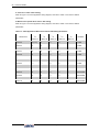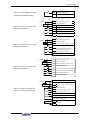
1
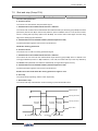
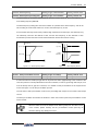
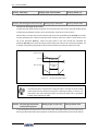
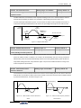
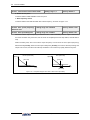
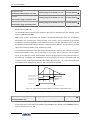
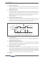
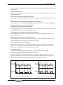
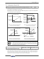
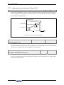
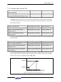
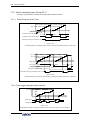
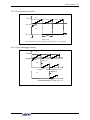
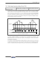
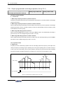
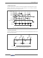
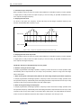
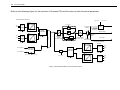
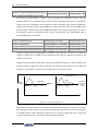
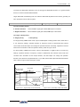
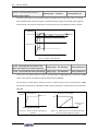
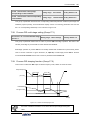
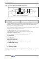
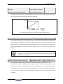
176
Function Details
FA.2.29
Linkage balance function
Setting range: 0~3
Factory default: 0
0: Void
1: Current balance
With reference to the load current of the master device, each slave device will automatically conduct
fine adjustment to the output of local device so as to keep consistency with the master device’s current.
2. Torque balance
With reference to the torque of the master device, each slave device will automatically conduct fine
adjustment to the output of local device so as to keep consistency with the master device’s torque.
3: Power balance
With reference to the power of the master device, each slave device will automatically conduct fine
adjustment to the output of local device so as to keep consistency with the master device’s torque.
FA.2.30
Linkage balancing gain
Setting range: 0.001~10.000
Factory default: 1.000
When the linkage balancing function is effective, this parameter is used to set the adjusting gain
output by this device, and it is only effective for the slave device. The higher the gain is, the higher
the amplitude of the self-balancing adjustment is.
7.37 Zero-speed torque and position control (Fb.2 group)
Fb.2.18
Automatic shift frequency
Setting range: 0.0~5.00Hz
Fb.2.19
Automatic shift switching cycle
Setting range: 0.10 ~ 2.00Sec. Factory default: 0.30
Factory default: 1.00
Combined with the multifunctional input terminal (Function No. 67), it is especially used for transmission
machineries with mechanical shifting function (e.g. machine tool spindle drive). This parameter is used
to set the operating frequency and FWD and REV shift cycle when the function is valid.
Fb.2.20
Zero frequency torque holdup
Setting range: 0~ 2
Factory default: 0
(DC bind-type brake preferred)
This parameter is to set the bind-type brake function at 0 speed. When it is set to 1, the actions on DC
are completely identical. The electronic bind-type brake at that time can ensure the motor completely
not rotating under the drag of load.
In the VC control mode with PG feedback, if it is set to 2, the equipment will output 0 speed torque in the
mode of position locking. Even if it is dragged by loads, the motor axis will not rotate.
Fb.2.21
Position locking gain
Setting range: 0.01 ~ 10.00
Factory default: 1.00
When the zero-frequency torque is kept at 2, this parameter is used to set the gains between the motor
output torque and the axis deviation. The larger the number is, the higher the 0 speed torque is. If the
value is too high, 0 speed ventilation may be resulted in.
V350 Low-Power Closed-Loop Vector Inverter
User Manual