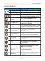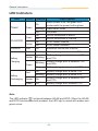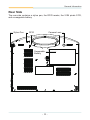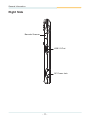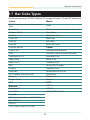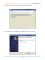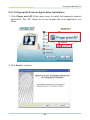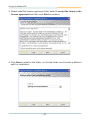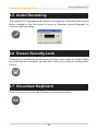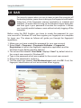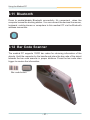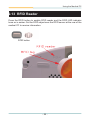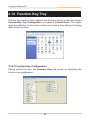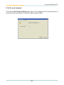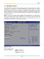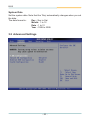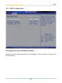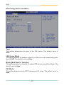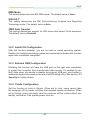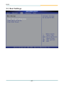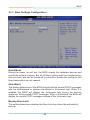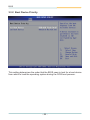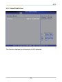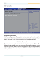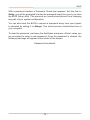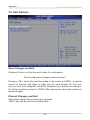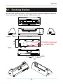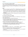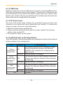
1
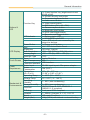
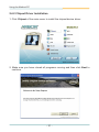
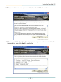
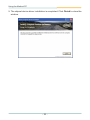
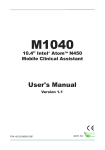
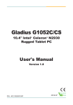
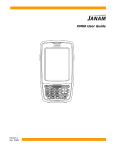
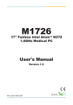
M1255
12" AtomTM Portable Medical PC
User's Manual
Version 1.1
Tested To Comply
With FCC Standards
P/N: 4042125500110P
FOR HOME OR OFFICE USE
2011.09
This page is intentionally left blank.
-2-
Index
Contents
Copyright Notice.........................................................................i
Declaration of Conformity.........................................................i
About This User's Manual.......................................................iii
Technical Support....................................................................iii
Warranty....................................................................................iv
Instructions for Rechargeable Battery Pack...........................v
General Conditions of Storage................................................vi
Chapter 1 - General Information...............................................1
1.1 Packing List........................................................................2
1.2 Ordering Information..........................................................3
1.3 Specifications.....................................................................3
1.4 Overview.............................................................................5
1.5 Dimensions.........................................................................6
1.6 Location of Buttons and Indicators..................................7
1.7 Bar Code Types................................................................12
Chapter 2 - Using the Medical PC..........................................13
2.1 Getting Started.................................................................14
2.2 Periodic Cleaning & Disinfection....................................14
2.3 Docking & Undocking......................................................16
2.4 Driver Installation.............................................................18
2.4.1 Touch Screen Driver Installation..........................18
2.4.2 Chipset Driver Installation....................................21
2.4.3 Graphics Driver Installation..................................24
2.4.4 Audio Driver Installation........................................27
2.4.5 LAN Driver Installation..........................................28
2.4.6 Wireless LAN Driver Installation..........................30
2.4.7 Bluetooth Driver Installation.................................36
2.4.8 RFID Driver Installation.........................................40
2.4.9 RS-232 Driver Installation.....................................43
2.4.10 Fingerprint Scanner Driver Installation.............44
2.4.11 Fingerprint Scanner Application Installation.....46
2.4.12 FunctionKey Interface Installation.....................49
-I-
Index
2.5 Audio Recording...............................................................50
2.6 Screen Security Lock.......................................................50
2.7 On-screen Keyboard........................................................50
2.8 SAS....................................................................................51
2.9 Video Recording...............................................................55
2.10 Camera............................................................................56
2.11 Bluetooth.........................................................................57
2.12 Bar Code Scanner..........................................................57
2.13 RFID Reader....................................................................58
2.14 Function Key Tray..........................................................59
2.14.1 Function Key Configuration................................59
2.14.2 Lock Interval.........................................................60
Chapter 3 - BIOS......................................................................61
3.1 BIOS Main Setup..............................................................62
3.2 Advanced Settings...........................................................63
3.2.1 IDE Configuration.................................................64
3.2.2 Install OS Configuration.......................................66
3.2.3 External USB Configuration.................................66
3.2.4 Cradle Configuration............................................66
3.3 Boot Settings....................................................................67
3.3.1 Boot Settings Configuration................................68
3.3.2 Boot Device Priority..............................................69
3.3.3 Hard Disk Drives...................................................70
3.4 Security.............................................................................71
3.5 Exit Options......................................................................73
Appendix..................................................................................75
A.1 Docking Station...............................................................76
A.1.1 Connecting an External CRT................................77
A.1.2 External Serial Port (COM)...................................77
A.1.3 LAN Port.................................................................77
A.1.4 USB Ports...............................................................78
A.1.5 DC Power Input......................................................78
A.1.6 LED Indicator on Docking Station.......................78
- II -
Copyright Notice
All Rights Reserved.
The information in this document is subject to change without prior notice in
order to improve the reliability, design and function. It does not represent a
commitment on the part of the manufacturer.
Under no circumstances will the manufacturer be liable for any direct, indirect,
special, incidental, or consequential damages arising from the use or inability
to use the product or documentation, even if advised of the possibility of such
damages.
This document contains proprietary information protected by copyright.
All rights are reserved. No part of this manual may be reproduced by any
mechanical, electronic, or other means in any form without prior written
permission of the manufacturer.
Declaration of Conformity
CE
This product has passed the CE test for environmental specifications when
shielded cables are used for external wiring. We recommend the use of
shielded cables. This kind of cable is available from ARBOR. Please contact
your local supplier for ordering information.
This product has passed the CE test for environmental specifications. Test
conditions for passing included the equipment being operated within an
industrial enclosure. In order to protect the product from being damaged by
ESD (Electrostatic Discharge) and EMI leakage, we strongly recommend the
use of CE-compliant industrial enclosure products.
FCC Class B
This device complies with part 15 of the FCC Rules. Operation is subject to
the following two conditions: (1) This device may not cause harmful interference, and (2) this device must accept any interference received, including
interference that may cause undesired operation.
This equipment has been tested and found to comply with the limits for a
Class B digital device, pursuant to part 15 of the FCC Rules. These limits
are designed to provide reasonable protection against harmful interference
when the equipment is operated in a residential environment. This equipment
generates, uses, and can radiate radio frequency energy and, if not installed
and used in accordance with the instructions, may cause harmful interference
to radio communications. Operation of this equipment in a residential area is
-i-
likely to cause harmful interference in which case the user will be required to
correct the interference at his own expense.
IEC 60601-1/EN60601-1/EN60601-1-2
This product complies with the system standard IEC 60601-1 Medical Electrical
Equipment Part 1: General Requirements for Safety. And therefore, the product
is exclusively interconnected with IEC 60601-1 certified equipment in the patient
environment.
Equipment connected to the analog or digital interfaces of the unit must comply
with the respective IEC standards (e.g. IEC 60601-1 for medical equipment).
Furthermore all configurations shall comply with the current version of the
standard for SYSTEMS IEC 60601-1-1. Everybody who connects additional
equipment to the signal input part or signal output part configures a medical
system, and is therefore responsible that the system complies with current
version of the requirements of the system standard IEC 60601-1-1. If in doubt,
consult the technical service department or your local representative.
RoHS
ARBOR Technology Corp. certifies that all components in its products are in
compliance and conform to the European Union’s Restriction of Use of Hazardous Substances in Electrical and Electronic Equipment (RoHS) Directive
2002/95/EC.
The above mentioned directive was published on 2/13/2003. The main purpose of the directive is to prohibit the use of lead, mercury, cadmium, hexavalent chromium, polybrominated biphenyls (PBB), and polybrominated diphenyl
ethers (PBDE) in electrical and electronic products. Member states of the EU
are to enforce by 7/1/2006.
ARBOR Technology Corp. hereby states that the listed products do not contain
unintentional additions of lead, mercury, hex chrome, PBB or PBDB that exceed a maximum concentration value of 0.1% by weight or for cadmium exceed
0.01% by weight, per homogenous material. Homogenous material is defined
as a substance or mixture of substances with uniform composition (such as solders, resins, plating, etc.). Lead-free solder is used for all terminations (Sn(9696.5%), Ag(3.0-3.5%) and Cu(0.5%)).
SVHC / REACH
To minimize the environmental impact and take more responsibility to the earth
we live, Arbor hereby confirms all products comply with the restriction of SVHC
(Substances of Very High Concern) in (EC) 1907/2006 (REACH --Registration,
Evaluation, Authorization, and Restriction of Chemicals) regulated by the European Union. All substances listed in SVHC < 0.1 % by weight (1000 ppm).
- ii -
About This User's Manual
This user's manual provides general information and installation instructions
about the product. This User’s Manual is intended for experienced users and
integrators with hardware knowledge of personal computers. If you are not
sure about any description in this booklet. please consult your vendor before
further handling.
Technical Support
All ARBOR products are built to the most accurate specifications to ensure
reliable performance in the harsh and demanding conditions typical of industrial environments. Whether your new Advantech equipment is destined for
the laboratory or the factory floor, you can be assured that your product will
provide the reliability and ease of operation. Your satisfaction is our primary
concern. We want you to get the maximum performance from your products.
So if you run into technical difficulties, we are here to help. For the most frequently asked questions, you can easily find answers in your product documentation. These answers are normally a lot more detailed than the ones
we can give over the phone. So please consult this manual first. If you still
cannot find the answer, gather all the information or questions that apply to
your problem, and with the product close at hand, call your dealer. Our dealers are well trained and ready to give you the support you need to get the
most from your products. In fact, most problems reported are minor and are
able to be easily solved over the phone. We are always ready to give advice
on application requirements or specific information on the installation and operation of any of our products. Please do not hesitate to call or e-mail us at:
http://www.arbor.com.tw
E-mail: [email protected]
Contact Information
Add: 10F., No.700, Zhongzheng Rd., Zhonghe Dist., New Taipei City
235, Taiwan
TEL: 886-2-8226-9396
- iii -
Warranty
This product is warranted to be in good working order for a period of one year
from the date of purchase. Should this product fail to be in good working order
at any time during this period, we will, at our option, replace or repair it at no
additional charge except as set forth in the following terms. This warranty
does not apply to products damaged by misuse, modifications, accident or
disaster.
Vendor assumes no liability for any damages, lost profits, lost savings or any
other incidental or consequential damage resulting from the use, misuse of,
or inability to use this product. Vendor will not be liable for any claim made by
any other related party.
Vendors disclaim all other warranties, either expressed or implied, including but
not limited to implied warranties of merchantibility and fitness for a particular
purpose, with respect to the hardware, the accompanying product’s manual(s)
and written materials, and any accompanying hardware. This limited warranty
gives you specific legal rights.
Return authorization must be obtained from the vendor before returned
merchandise will be accepted. Authorization can be obtained by calling or
faxing the vendor and requesting a Return Merchandise Authorization (RMA)
number. Returned goods should always be accompanied by a clear problem
description.
- iv -
Instructions for Rechargeable Battery Pack
How to recharge:
• To recharge Lithium-ion battery, install it into the computer and then connect
the power adapter to the power input plug of the computer.
• The battery will be fully charged within 2-4 hours (depending on the capacity
of the battery). When finished charging, the charge indicator will turn on
steadily in green and then it’s recommended to remove the adapter from
the computer.
• It’s recommended not to recharge intermittently, which means not plugging
and unplugging the power adapter frequently in short period of time.
• It’s recommended to turn off the computer before charging.
• Do not use the power adapter that is not made for your computer. Supplying
the computer with inappropriate voltage may cause harm to the battery or,
even worse, may burn the computer.
How to use:
• It’s recommended to supply power via the adapter without the battery
installed, while you are to use the computer for a long time. And reinstall
the battery before you go out.
• The lithium-ion battery is currently one of the most popular battery packs
right now. The biggest advantage is that it has no memory effect that users
needn’t worry about. Users can charge the battery anytime whether the
battery is fully drained or not. However, it’s recommended that users drain the
battery until the system shows power shortage warning and then recharge
the battery. Doing so is helpful to the reliability of using the battery.
• Don’t use the battery pack as a power supply for other equipment.
How to store:
• Don’t expose the battery to elevated heat situations such as under direct
sunlight in a car or near fire.
• Don’t disassemble the battery, or the battery leakage might cause skin or
eye injury. If electrolyte leaking from the battery pack contacts your skin
or clothing, immediately flush it with running water. If it splashes in eye,
rinse the eye at least 15 minutes with clean water and then seek medical
attention.
• To avoid battery leakage or explosion, don’t discard the battery into water
or fire, or near a heat source such as a gas stove or an oven.
• Use the appropriate container to store the battery such as a paper box. Do
not allow a metal object to touch the terminals of the battery.
-v-
• When storing for a long period of time, keep the battery approximately at
the charging state of 60 ~ 80% and regularly use it. The battery should be
completely discharged and recharged once each month to condition the
cells inside the battery to ensure the battery delivers the most available
capacity.
• The battery consists of precision electrical components and cells. Do not
drop or hit the battery.
General Conditions of Storage
Temperature: 0°C ~ 60°C
Humidity: 65 ± 20RH
The table listed below describes how long the battery will be empty with the
respective storage temperature conditions.
Storage Period
Storage Temperature
1 Month
-20°C ~ 60°C
3 Months
-20°C ~ 45°C
1 Year
-20°C ~ 20°C
Note:
• When the operating temperature is above 60°C or below 0°C, battery
charging stops.
• When the operating temperature exceeds 65°C, battery discharging stops.
• While the medical computer is docked into the docking station, the internal
battery has the higher priority to be charged; the battery that installed in the
external charging slot of the docking station is not charged until the internal
battery is fully charged.
- vi -
General Information
1
Chapter 1
General Information
Chapter 1 - General Information
-1-
General Information
1.1 Packing List
1 x M1255
1 x DTC-1255
Accessory Package:
1 x User’s Manual
1 x Driver CD
1 x Power Cord (left: French standard cordset)
1 x Power Cord (right: American standard
cordset)
1 x Power Adapter
1 x Screws Kit
Before up and running, please make sure the package contains all of above
accessories.
If any of the above items is damaged or missing, contact your vendor
immediately.
-2-
General Information
1.2 Ordering Information
M1255/N270-C22
12.1" Intel® Atom™ N270 portable medical PC w/
resistive touch screen, 65W power adapter, docking
station (1 x RJ-45/1 x RS-232/3 x USB/1 x VGA/1 x
charging Bay) w/ VESA-75 holes
BAT-1255
External 1880mAH 4-cell Li-battery
1.3 Specifications
Model Name
System
Medical Panel PC M1255
Intel® Atom™ N270, 1.6GHz FSB 533MHz
CPU
512K Cache
Graphics
Intel® GMA950
Controller
1 x 200-pin SO-DIMM DDR2 2GB Memory
Memory
(module installed)
Chipset
Intel® 945GSE + ICH7M
Audio
Azalia HD audio
Storage
1 x 32GB 1.8" PATA SSD installed
1 x Realtek 8111 PCI-E GbE LAN
Connectivity
1 x 802.11 b/g/n Mini PCIe Wireless LAN card
1 x Bluetooth Module
Security
Biometric recognition by Fingerprint scanner
Camera
Color, 2.0 Megapixel CMOS Camera
13.56MHz RFID Reader with ISO 15693
RFID
Support
I/O
1 x USB 2.0 Port
Internal 1880mAh/11.1V 3-cell Li-battery
Battery
External 1880mAh/14.8V 4-cell Li-battery
-3-
General Information
1 x 5-way function key (brightness/volume/
WLAN on/off)
1 x Screen security lock button
1 x On-screen keyboard button
1 x Audio record button
1 x Video record button
Function Key
1 x SAS button (Ctrl + Alt + Del)
Buttons &
1 x Camera capture button
LED
1 x Bluetooth on/off button
1 x RFID read trigger button
1 x Barcode scan trigger button
LED Indicator
1 x Battery status LED
1 x WLAN/RFID on/off LED
Power & Bluetooth are covered by the
respective buttons
Power Button
1 x Power on/off button
12.1" TFT Active Matrix Panel
Size
220 cd/m² (typical)
Brightness
1024 x 768 (XGA) w/ 262,144 colors
LCD Display
Max. Resolution
+70º ~ -70º (H), +55º ~ -70º (V)
Viewing Angle
CCFL
Backlight Type
Analog Resistive
Type
Touch Screen Light Transparency 80%
Controller Interface USB Interface
DC 19V input by ext. 65w power adapter
Power Input
Power
Power
Requirement
14w (AVG.)
Consumption
307 x 25 x 277 mm
Dimensions
(12.09" x 0.98" x 10.91")
(W x D x H)
0 ~ 40ºC (32 ~ 104ºF)
Operating Temp.
-20 ~ 60ºC (-4 ~ 140ºF)
Storage Temp.
Operating
8 ~ 80% (non-condensing)
Humidity
Mechanical & Storage Humidity
8 ~ 90% (non-condensing)
Environmental
CE/FCC Class B, CCC, EN60601-1
EMI/EMC
EN60601-1-2 compliant
Front panel IP54 compliant
IP Rating
5 ~ 500Hz (3 axises: X, Y, Z), 1G PTP
Vibration
10G peak (11m Sec.)
Shock
1.6kg (3.5 lb) with internal + external battery
Weight (Net)
-4-
General Information
1.4 Overview
Front View
Rear View
-5-
General Information
1.5 Dimensions
25
277
307
Unit: mm
-6-
General Information
1.6 Location of Buttons and Indicators
The front panel contains power button, fingerprint scanner, function control
buttons, LED indicators etc.
Front Side
12.1" LCD (w/ Touch Panel)
Barcode Scan Trigger Button
RFID Reader Button
5-Way Directional Button
FingerPrint Scanner
Power Button (w/ LED)
Audio Recorder Button
Screen Security Lock Button
On-Screen Keyboard Button
SAS Button
Viedo Recorder Button
Camera Button
Bluetooth On/Off Button (w/ LED)
Batt. Charger LED
-7-
WLAN/RFID ON LED
General Information
Control Buttons
Button
Description
Bar Code Scanner Press to trigger the bar code scanner.
RFID Reader
Press to enable/disable the RFID reader.
Speaker volume
Press the upper/lower button to
increase/decrease the speaker volume.
WLAN
Press to enable/disable the Wi-Fi
connection.
LCD backlight
Press the left/right button to decrease/
increase LCD backlight.
Power
Press to turn the power on/off or to wake
the system up from hibernation mode.
Audio Record
Press to bring up the recorder
application.
Screen Security
Lock
Press to lock/unlock the touchscreen.
On-screen
Keyboard
Press to bring up or close the on-screen
keyboard.
SAS
Press to lock/log on to the system
(Ctrl+Alt+Del).
Video Record
Press to start video recording. Press
again to stop recording.
Camera
Press to take pictures.
Bluetooth
Press to enable/disable Bluetooth
connectivity.
-8-
General Information
LED Indicators
LED
Power
Color Status
On
When power is on, the green LED
underneath the power button glows
Blinking
Hibernation mode
Off
No power
On
WLAN connection is active
Off
WLAN connection is inactive
On
RFID reader enabled
Off
RFID reader disabled
Blue
On
Bluetooth connection is active
Red
Blinking
Battery charge level is below 20%
Amber
Blinking
Battery charge level is between 20%
and 70%
Blinking
Battery charge level is between 70%
and 99%
On
Battery charge level exceeds 100%
On
Battery charge level is below 10%
Blinking
Battery charge level is below 20%
Amber
On
Battery charge level is between 20%
and 70%
Green
On
Battery charge level exceeds 70%
Green
Green
WLAN/RFID
Amber
Bluetooth
Battery
Charging
Green
Red
Battery
Discharging
Description
Note:
is shared between WLAN and RFID. When the WLAN
The LED indicator
and RFID functions are both enabled, the LED light is mixed with amber and
green colors.
-9-
General Information
Rear Side
The rear side contains a stylus pen, the RFID reader, the 2.0M pixels CCD,
and a swappable battery.
Stylus Pen
RFID
Camera Lens
Swappable
Battery
- 10 -
General Information
Right Side
Barcode Scanner
USB 2.0 Port
DC Power Jack
- 11 -
General Information
1.7 Bar Code Types
As following format, M1255 Medical PC supports these 1D and 2D barcodes.
Linear
Matrix
BC412 (requires end-user license from
IBM)
Aztec
China Post
Chinese Sensible Code (Han Xin Code)
Codabar (NW7)
Data Matrix
Code 11
Grid Matrix Code
Code 128
MaxiCode
Code 32
QR Code
Code 39
Micro QR Code
Code 93 and 93i
Postal
Code 2 of 5
Intelligent Mail Barcode
EAN
(formerly 4-state customer barcode)
Interleaved 2 of 5
Australian Post
Label Code
British Post
Matrix 2 of 5
Canadian Post
MSI
ID-tag (UPU 4-state)
Plessey
Japanese Post
PosiCode
Netherlands (KIX) Post
GS1 DataBar (formerly RSS)
Korea Post
Telepen
Planet Code
Trioptic Code
Postnet
UPC
OCR
Stacked
OCR-A
Codablock F
OCR-B
Code 16K
OCR MICR (E 13 B)
Code 49
GS1 Composite (formerly EAN/UCC)
MicroPDF417
PDF417
TCIF Linked Code 39 (TLC39)
- 12 -
Using the Medical PC
2
Chapter 2
Using the Medical PC
Chapter 2 - Using the Medical PC
- 13 -
Using the Medical PC
2.1 Getting Started
This chapter will help you have your medical PC up and running smoothly,
and give you the information about how to utilize the various functions.
The medical PC supports Windows XP Professional and Windows Vista.
Before installing operating system and driver utilities, you should prepare your
own USB keyboard, USB CD ROM drive, and the power adapter included
in the package if the battery charge level is insufficient. When the operating
system on your computer is ready, please use the accompanying CD ROM to
install the drivers and utilities for the respective devices. The following sections
will guide you through the drivers and utilities installation step by step.
2.2 Periodic Cleaning & Disinfection
It is strongly recommended that users follow the cleaning and disinfection
instructions described below to ensure proper maintenance activities.
Procedures for Cleaning & Disinfection
1. Always power off your unit first, when you clean or disinfect it.
2. To wipe the outer case, use lint-free cloth, lightly moistened with warm
water and a mild, non-abrasive cleaning solution made of either:
• 70% isopropyl alcohol
• 10% bleach solution
• Dimethyl ethylbenzyl ammonium chlorides 0.125%, dimethyl benzyl
ammonium chlorides 0.125%, Isopropyl alcohol 14.850% (Sani-Cloth®)
• Isopropanol 17.2%; Diisobutylphenoxyethyl dimethyl bezyl ammonium
chlorides 0.28% (CaviCide®)
3. The touch screen can be wiped down (e.g. to remove fingerprints) during
operation while powered on using standard computer screen solution.
- 14 -
Using the Medical PC
Caution:
•
•
•
•
•
•
•
•
•
Do not spill liquids on or around the Medical PC.
Do not use other solutions than the ones mentioned above.
Do not touch, press or rub the display panel with abrasive cleaning
compounds, instruments, brushes, or rough-surface materials.
Never spray cleaning liquids or foam onto the Medical PC or soak it for
cleaning.
Do not use solvents to clean the unit.
Do not clean, disinfect, or sterilize any part of the system by autoclaving or
with the use of ethylene oxide gas; doing so may damage the unit.
Never spray or squirt any type of liquid onto the Medical PC; if a spray, gel
or foam is needed, spray the liquid onto a cloth and then use the cloth to
wipe or rub down the component.
Always avoid contamination to minimize the need for disinfectants.
Do not spill, spray, or squirt liquids to the power block and the power
cable.
- 15 -
Using the Medical PC
2.3 Docking & Undocking
The docking station (DKS-1255) is equipped with one RJ-45, one VGA, three
USB connectors and one battery charging bay. It’s useful for users to connect
multiple peripheral devices at the same time.
Caution:
The docking station comes with an solenoid valve for locking the computer,
and the only way of taking the computer off the docking station is passing
identity recognition. Thus, before sliding the computer into the docking station,
make sure you are immediately to install operating system, the fingerprint
scanner driver/application, and the function key application (these are the
necessary software for undocking). Otherwise, the computer is locked by the
solenoid of the docking station until the necessary software are ready.
To implement the undocking mechanics, please follow the instructions below:
1. Install the operating system for the computer (a USB type CD ROM drive
is needed).
2. After the operating system is installed, the next is to install the driver for
fingerprint scanner. Put the CD ROM into the CD ROM drive and then
please refer to section 2.4.10 Fingerprint Scanner Driver Installation
step by step.
3. When the fingerprint scanner driver is installed, the next is to install the
fingerprint scanner application. Refer to section 2.4.11 Fingerprint Scanner
Application Installation for the installation procedures.
4. The next is to install the function key application. please refer to section
2.4.12 FunctionKey Interface Installation.
5. With the fingerprint scanner driver/application and function key interface
installed, you are now available to remove your computer from the docking
station by logging on the system again. There are three ways to log on the
system: clicking Start > Log Off to log off and log on, pressing the Ctrl-AltDel combination keys, or simply pressing the SAS function button.
- 16 -
Using the Medical PC
Note: When logging on the system, you are prompted to swipe your finger
across the fingerprint scanner. Before using this fingerprint identification
function, make sure you have registered at least one fingerprint via the
fingerprint registration utility. Please refer to section 2.8 SAS for further details
about fingerprint registration and identification. Otherwise, you should click
Cancel and enter password to log on.
The computer will be unlocked for 20 seconds by default, with an open-lock
icon showing on the screen, when ID verification is successfully accepted.
During the unlocked interval, please press the button on the right side to
release the hook which fixes the computer, and now you can take the computer
away by holding its handle. See the figure below.
Release Button
If the computer isn’t removed from docking station in 20 seconds, the docking
station will lock it again and a close-lock icon shows up on the screen. The
lock interval setting can be configured by users. Please refer to section 2.14
Function Key Tray for changing lock interval.
- 17 -
Using the Medical PC
2.4 Driver Installation
2.4.1 Touch Screen Driver Installation
1. After you put the CD ROM into the CD-ROM drive, the driver and utility
installation main menu appears. Click Touch Screen to install the driver
for touch screen.
2. When you see the welcome wizard, click Next to continue.
- 18 -
Using the Medical PC
3. Please read the license agreement first, and click I Agree to continue.
4. Click Browse to change the installation directory, or immediately click
Install to continue.
- 19 -
Using the Medical PC
5. Please wait for a while until the progress bar completes.
6. The installation is completed. Click Finish to close this window.
- 20 -
Using the Medical PC
2.4.2 Chipset Driver Installation
1. Click Chipset of the main menu to install the chipset device driver.
2. Make sure you have closed all programs running and then click Next to
continue.
- 21 -
Using the Medical PC
3. Please read the license agreement first, and click Yes to continue.
4. Please read the Readme file for system requirements and installation
information, and click Next to continue.
- 22 -
Using the Medical PC
5. The chipset device driver installation is completed. Click Finish to close the
window.
- 23 -
Using the Medical PC
2.4.3 Graphics Driver Installation
1. Click VGA of the main menu to install the graphics device driver.
2. Make sure you have closed all programs running and then click Next to
continue.
- 24 -
Using the Medical PC
3. Please read the license agreement first, and click Yes to continue.
4. Please read the Readme file for system requirements and installation
information, and click Next to continue.
- 25 -
Using the Medical PC
5. The graphics device driver installation is completed. Click Next to continue.
6. After installing the graphics device driver, click Finish with Yes radio button
selected to restart your computer to have the changes take effect, or with
No to restart this computer later.
- 26 -
Using the Medical PC
2.4.4 Audio Driver Installation
1. Click Audio of the main menu to install the audio device driver.
2. Click Next to continue.
- 27 -
Using the Medical PC
3. After installing the audio device driver, click Finish with Yes radio button
selected to restart your computer to have the changes take effect, or with
No to restart this computer later.
2.4.5 LAN Driver Installation
1. Click LAN of the main menu to install the LAN device driver.
- 28 -
Using the Medical PC
2. Click Next to continue.
3. Click Install to start installation, or Back to go back to the previous step.
- 29 -
Using the Medical PC
4. Click Finish to close the wizard window.
2.4.6 Wireless LAN Driver Installation
1. Click WiFi of the main menu to install the wireless LAN device driver.
- 30 -
Using the Medical PC
2. Select preferred language.
3. Wait for the process.
- 31 -
Using the Medical PC
4. Click “Next >”.
5. Choose “I accept the terms of the license agreement” and click “Next >”.
- 32 -
Using the Medical PC
6. Select preferred type and Click “Next >”.
7. Click “Next >”.
- 33 -
Using the Medical PC
8. Click “Next >”.
9. Click “Next >” to create shortcuts.
- 34 -
Using the Medical PC
10. Wait for the process.
11. Click “Finish” to complete all process.
- 35 -
Using the Medical PC
2.4.7 Bluetooth Driver Installation
1. Click Bluetooth of the main menu to install the Bluetooth device driver.
2. A dialog box shows up. Click the down arrow to drop down the selection
menu and choose a language item and then click OK to continue.
- 36 -
Using the Medical PC
3. Check the driver information and click Next to continue.
4. Please read the license agreement first; select I accept the terms in the
license agreement and then click Next to continue.
- 37 -
Using the Medical PC
5. If you want to create shortcuts to Startup folder or Desktop, tick the check
boxes beside the text label and then click Next to continue.
6. Click Next to install to this folder, or click Change to install to a different
folder.
- 38 -
Using the Medical PC
7. Click Install to start installation, or click Back to go back to the previous
step.
8. After the installation is completed, click Finish to close the window.
- 39 -
Using the Medical PC
2.4.8 RFID Driver Installation
1. Click RFID of the main menu to install the RFID and USB devices driver.
The “AP” letters on its icon implies this is an application, not driver.
2. Read the information and then click Next to continue.
- 40 -
Using the Medical PC
3. Click Next to install to this folder, or click Browse to install to a different
folder.
4. The application is being installed, please wait for a while.
- 41 -
Using the Medical PC
5. Click Finish to complete the installation.
Note:
After installation, the RFID device information in Device Manager may appear
with an exclamation mark. To solve this problem, please manually update the
driver for this device just once.
- 42 -
Using the Medical PC
2.4.9 RS-232 Driver Installation
1. Click RS-232 of the main menu to install the com port devices driver.
2. The driver is being installed, please wait for a while and then the installation
will automatically completed.
- 43 -
Using the Medical PC
2.4.10 Fingerprint Scanner Driver Installation
1. Click Finger print of the main menu to install the fingerprint scanner
driver.
2. Click Next to continue.
- 44 -
Using the Medical PC
3. Click Install to start installation.
4. The installation is completed. Click Finish to close the window.
- 45 -
Using the Medical PC
2.4.11 Fingerprint Scanner Application Installation
1. Click Finger print AP of the main menu to install the fingerprint scanner
application. The “AP” letters on its icon implies this is an application, not
driver.
2. Click Next to continue.
- 46 -
Using the Medical PC
3. Please read the license agreement first; select I accept the terms in the
license agreement and then click Next to continue.
4. Click Next to install to this folder, or click the folder icon to locate a different
path for installation.
- 47 -
Using the Medical PC
5. The installation is in progress. Wait for a while until the progress bar reaches
the end.
6. Click Finish to complete the installation.
- 48 -
Using the Medical PC
2.4.12 FunctionKey Interface Installation
1. Click Function keys of the main menu to install the functionKey Interface
as a component into the control panel.
2. Click Finish to complete the installation.
Note: With this utility installed, an on-screen keyboard, which is different to
the Windows on-screen keyboard, will automatically show up when users are
to log on to the system. It is useful especially when no physical keyboard is
available.
- 49 -
Using the Medical PC
2.5 Audio Recording
The medical PC is equipped with a built-in microphone. Press the audio record
button located on the front panel to bring up Windows Sound Recorder for
voice or audio recording.
2.6 Screen Security Lock
Press once to disable the touch screen function; press again to enable. While
the touch screen is disabled, you can still control your computer via keyboard/
mouse.
2.7 On-screen Keyboard
Press to bring up or close the Windows on-screen keyboard.
- 50 -
Using the Medical PC
2.8 SAS
For security reason when you are to leave or take the computer off
the docking station, press once to bring up the fingerprint verification
dialog box (if the fingerprint scanner application is installed and
enabled). Or press twice to bring up the password logon dialog box
and then type in your password to access the computer. It allows
you to quickly switch between users without actually logging off the
computer.
Before using the SAS function, you have to create the password for your
user account in Windows XP and then register your fingerprint as a template
for logon use. The steps as follows will guide you through the fingerprint
registration.
1. Make sure you have created the password for your user account.
2. Select Start > Programs > Fingerprint Software > Fingerprint
Registration to launch the fingerprint registration application and the
Windows Logon Setting window appears.
3. The column field labeled ‘User Name’ displays ‘User1’ by default which is
the current user account in Windows XP.
4. Type in the password which was created for the current user account.
5. Retype the password to confirm it.
6. Tick the check box labeled ‘Use WindowsLogon’ and click OK. If not, the
fingerprint identification will not be launched when logging.
- 51 -
Using the Medical PC
7. After the Windows Logon Setting is finished, the Fingerprint Registration
window appears. Click on any of the fingers shown on screen and press
next.
8. With the selected finger appearing in blue, the 'Next' button becomes
available to be clicked. Click it to continue.
- 52 -
Using the Medical PC
9. When this window shows up, swipe your finger across the finger identification
sensor on the top right of your computer.
10. Please swipe your finger again until the counter below shows OK that
means your fingerprint registration is successfully accepted.
- 53 -
Using the Medical PC
11. The finger you have just registered appears in green. Click Finish to close
the window. And then a dialog box appears to ask you to restart Windows;
press Yes to restart immediately.
12. After the fingerprint template is registered, you can press the SAS button
to bring up the fingerprint identification window. To access your computer,
swipe your finger across the fingerprint scanner, or click Cancel and then
enter password instead for identity verification.
- 54 -
Using the Medical PC
2.9 Video Recording
Press video record button to launch the CCD video recorder and the window
shows up.
Press again to enable the CCD lens, which you will hear the two smooth
sounds of music. Now you can see the real image shown in the window. Press
the button; you may see a pop-up dialog box asking for video compression
mode selection. Click OK to start video recording and you can see the hint
text showing that the video is saving on the tool bar. Press the button to stop
recording and you can see the hint text showing that the video is saved. You
can find the recorded video files in the path of C:\Documents and Settings\
[user account]\My Documents\ccd.
- 55 -
Using the Medical PC
2.10 Camera
Press the camera button to launch the CCD camera and the window shows
up.
Having enabled the CCD lens by pressing the button again, you will hear the
two smooth sounds of music. Now you can see the real image shown in the
window. Press the button, you can hear a shutter sound, to take a picture and
you can see the hint text showing that the image is saved in BMP file format.
Pleas find the saved files in the path of C:\Documents and Settings\[user
account]\My Documents\ccd.
- 56 -
Using the Medical PC
2.11 Bluetooth
Press to enable/disable Bluetooth connectivity. It’s convenient when the
computer leaves the docking station. You can connect the devices like mouse,
keyboard, mobile phones or computers to this medical PC via the Bluetooth
wireless connection.
2.12 Bar Code Scanner
The medical PC supports 1D/2D bar codes for retrieving information of the
objects. Hold the computer by the handle and place the bar code of the object
towards the bar code scanner in proper distance. Press the bar code scan
trigger to receive the information.
Bar code button
- 57 -
Using the Medical PC
2.13 RFID Reader
Press the RFID button to enable RFID reader and the RFID LED indicator
turns on in amber. Get the RFID object near the RFID sensor at the rear of the
medical PC to receive information.
RFID button
- 58 -
Using the Medical PC
2.14 Function Key Tray
With the FunctionKey utility installed, see the figure below, a new item named
FunctionKey Tray Configuration is created in Control Panel. This applet
gives the definition list of function buttons and interval time setting of docking
station lock functions.
2.14.1 Function Key Configuration
Having clicked the icon, the Function Keys tab shows up displaying the
function key configuration.
- 59 -
Using the Medical PC
2.14.2 Lock Interval
Click the Lock Cradle Setting tab, type in the respected lock interval time in
seconds and click Apply to have the setting take effect.
- 60 -
BIOS
3
Chapter 3
BIOS
Chapter 3 - BIOS
- 61 -
BIOS
3.1 BIOS Main Setup
The AMI BIOS provides a Setup utility program for specifying the system
configurations and settings. The BIOS ROM of the system stores the Setup
utility. When you turn on the computer, the AMI BIOS is immediately activated.
Use the left/right arrow keys to highlight a particular configuration screen from
the top menu bar or use the down arrow key to access and configure the
information below.
Note: In order to increase system stability and performance, our engineering
staff are constantly improving the BIOS menu. The BIOS setup screens and
descriptions illustrated in this manual are for your reference only, may not
completely match what you see on your screen.
System Time
Set the system time.
The time format is:
Hour : 00 to 23
Minute : 00 to 59
Second : 00 to 59
- 62 -
BIOS
System Date
Set the system date. Note that the ‘Day’ automatically changes when you set
the date.
The date format is:
Day : Sun to Sat
Month : 1 to 12
Date : 1 to 31
Year : 1999 to 2099
3.2 Advanced Settings
- 63 -
BIOS
3.2.1 IDE Configuration
Primary/Secondary IDE Master/Slave
Select one of the hard disk drives to configure it. Press <Enter> to access its
the sub menu.
- 64 -
BIOS
IDE Configuration Sub Menu
Type
This setting determines the type of the IDE device. The default value is
Auto.
LBA/Large Mode
This setting enables or disables support for IDE drives with capacities greater
than 528MB. The default value is Auto.
Block (Multi Sector Transfer)
This setting enables or disables to support IDE drives using Block Mode. The
default value is Auto.
PIO Mode
This setting determines the IDE Programmed I/O mode. The default value is
Auto.
- 65 -
BIOS
DMA Mode
This setting determines the IDE DMA mode. The default value is Auto.
S.M.A.R.T
This setting determines the IDE Self-monitoring, Analysis and Reporting
Technology mode. The default value is Auto.
32Bit Data Transfer
This setting determines support for IDE drives that permit 32-bit accesses.
The default value is Enabled.
3.2.2 Install OS Configuration
With this function disabled, you are not able to install operating system.
Enable it for installing operating system and remember to disable this function
again after installation completed.
3.2.3 External USB Configuration
Disabling this function will have the USB port on the right side unavailable
to protect the computer from unauthorized data access. It’s enabled by default. Note when you decide to disable the external USB port, you'd better to
enable the supervisor password as well via BIOS setup utility. See section 3.3
Security for further details.
3.2.4 Cradle Configuration
Set this function to Lock or Unlock. When set to Lock, users cannot take
the computer off the cradle until they have passed identity verification. When
set to Unlock, users can easily take the computer off the cradle without any
identity verification if the system power turns on.
- 66 -
BIOS
3.3 Boot Settings
- 67 -
BIOS
3.3.1 Boot Settings Configuration
Quick Boot
During the power on self test, the BIOS checks the hardware devices and
counts the system memory. But all of these system tests are needed every
time you boot, and can be turned off to save time. Enable this setting to turn
those tests which are not needed.
Quiet Boot
This setting determines if the BIOS should hide the normal POST messages
with the motherboard or system manufacture’s full-screen logo. When it is
enabled, the BIOS will display the full-screen logo during the boot-up
sequence, hiding normal POST messages. When it is disabled, the BIOS will
display the normal POST messages instead of the full-screen logo.
Bootup Num-Lock
This setting determines whether the Num Lock key should be activated at
boot up.
- 68 -
BIOS
3.3.2 Boot Device Priority
This setting determines the order that the BIOS uses to look for a boot device
from which to load the operating system during the DOS boot process.
- 69 -
BIOS
3.3.3 Hard Disk Drives
This function displays the information of HDD detected.
- 70 -
BIOS
3.4 Security
Supervisor Password
Set Change Supervisor Password to enter and change the options of the
setup menus. When you select this function, the following message will appear at the center of the screen to assist you in creating a password.
Enter New Password:
Type the password, up to six characters in length, and press <Enter>. The
password typed now will clear any previously entered password from CMOS
memory. You will be asked to confirm the password. Type the password again
and press <Enter>. You may also press <ESC> to abort the selection and not
enter a password.
- 71 -
BIOS
With a password created, a Password Check item appears. Set this item to
Setup, you will be prompted to enter the password every time you try to enter
the BIOS Setup utility. This prevents an unauthorized person from changing
any part of your system configuration.
You can also have the BIOS to request a password every time your system
is rebooted by setting it to Always. This would prevent unauthorized use of
your computer.
To clear the password, just leave the field blank and press <Enter> when you
are prompted to enter a new password. Once the password is cleared, the
following message will appear at the center of the screen.
Password Uninstalled.
- 72 -
Appendix
3.5 Exit Options
Save Changes and Exit
Pressing <Enter> on this item and it asks for confirmation:
Save configuration changes and exit setup?
Pressing <OK> stores the selection made in the menus in CMOS - a special
section of memory that stays on after you turn your system off. The next
time you boot your computer, the BIOS configures your system according to
the Setup selections stored in CMOS. After saving the values the system is
restarted again.
Discard Changes and Exit
Exit system setup without saving any changes.
<ESC> key can be used for this operation.
- 73 -
BIOS
Load Optimal Defaults
When you press <Enter> on this item, you get a confirmation dialog box with
a message:
Load Optimal Defaults?
[OK]
[Cancel]
Pressing [OK] loads the BIOS Optimal Default values for all the setup
configurations.
<F9> key can be used for this operation.
- 74 -
Appendix
Appendix
Appendix
- 75 -
Appendix
A.1 Docking Station
116.109
By using the docking station, users can connect external peripheral devices,
such as a monitor, a serial device, USB devices etc.
391.301
144.939
USB 2.0 USB 2.0
VESA compliant
screw holes
Unit:
DC-IN
RS232
VGA
USB 2.0
LAN
- 76 -
Appendix
A.1.1 Connecting an External CRT
There is a 15-pin analog RGB interface connector located at the back of the
docking station for connecting a secondary display. The system can support
simultaneous display on both its LCD display and on the external CRT
display.
Note:
1. When you connect an external CRT or VGA-based monitor to the VGA
port of the docking station and if the external monitor appearance is
abnormal, please modify the display properties to set the external monitor
as the primary monitor. After the external monitor appearance becomes
normal, you can set the medical PC back to primary and then the problem
disappears.
2. The preferred resolution is 1024 x 768 because this is what the LCD Panel
needs to operate full screen.
A.1.2 External Serial Port (COM)
The docking station supports a serial port of D-SUB 9-pin male connector
which supports RS-232.
To connect the serial device, follow the steps below:
1. Turn off the Portable Medical PC system and the serial device.
2. Attach the interface cable of the serial device to the 9-pin D-SUB serial
connector. Be sure to fasten the retaining screws.
3. Turn on the computer and the attached serial device.
4. Refer to the serial device's manual for instructions to configure the
operation environment to recognize the new attached devices.
5. If the serial device needs specified IRQ or address, you may need to run
the CMOS setup to change the hardware device setup.
A.1.3 LAN Port
M1255 provides one Realtek 8111 10/100/1000Base-T Ethernet (RJ-45)
interface. For network connection, follow the instructions below:
1. Turn off the Medical PC system and the Ethernet hubs.
2. Plug in one end of cable from a 10/100/1000Base-T hub to the system's
RJ-45 jack.
3. Turn on the Medical PC system and the Ethernet hubs.
- 77 -
Appendix
A.1.4 USB Ports
M1255 provides four external USB ports to connect to external USB devices.
USB ports and devices are hot plug capable. Therefore any USB device can
be connected at all time without the need to power down your system. Note
that for many of these devices you will first have to install proper device drivers
before they can be recognized by the system.
A.1.5 DC Power Input
One end of the power cable is fitted with a standard power connector that
connects to any normal wall outlet (types differ per country). To connect the
system to power, follow the instructions below:
1. Make the system power switched off.
2. Plug the circular connector firmly into the circular socket of the docking
station or the medical PC.
3. For operation, power up the system.
A.1.6 LED Indicator on Docking Station
The LED indicator of the docking station only displays the status of the external
battery installed in the charging slot.
Color
Green
(charge level
above 70%)
Amber
(charge level
between 20
and 70%)
Red
(charge level
below 20%)
OFF
Status
Description
On
The external battery has full charged or stops
charging temporarily because the batteries
installed in the computer are charging with a
higher priority.
Blinking
External battery is charging.
On
The external battery stops charging temporarily
because the batteries installed in the computer
are charging.
Blinking
External battery is charging.
On
The external battery stops charging temporarily
because the batteries installed in the computer
are charging.
Blinking
External battery is charging.
No power
- 78 -
This page is intentionally left blank.
- 79 -