1
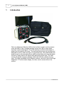
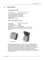
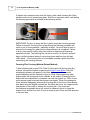
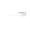
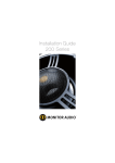
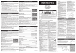
Lens Adjustment Module (LAM)
User Manual
493333301 Rev. C
April 2008
Lens Adjustment Module (LAM)
© 2008 Iteris Inc.
All rights reserved. No parts of this work may be reproduced in any form or by any means - graphic, electronic, or
mechanical, including photocopying, recording, taping, or information storage and retrieval systems - without the
written permission of the publisher.
Products that are referred to in this document may be either trademarks and/or registered trademarks of the
respective owners. The publisher and the author make no claim to these trademarks.
While every precaution has been taken in the preparation of this document, the publisher and the author assume no
responsibility for errors or omissions, or for damages resulting from the use of information contained in this document
or from the use of programs and source code that may accompany it. In no event shall the publisher and the author be
liable for any loss of profit or any other commercial damage caused or alleged to have been caused directly or
indirectly by this document.
Printed: April 2008 in Anaheim California, U.S.A.
Special thanks to:
All of our loyal Vantage customers and to all of the people
who contributed to this document, especially the Iteris
Vantage Product Support Team.
Technical Writer
Shawn Cummings
Graphics Design
Angie Wood
Contents
I
Table of Contents
Part I
Introduction
1
Part II
Specifications
2
Part III
Components
3
Part IV
Lights & Buttons
5
Part V
LAM Setup
7
Part VI
LAM Hook-Up Diagram
9
Part VII
Stand Alone Operation
11
Part VIII RZ-3 / RZ-4 FOV & Focus Procedure
12
Part IX
RZ-4C FOV & Focus Procedure
14
Part X
Customer Service & Support
17
Index
18
© 2008 Iteris Inc.
I
1
1
Lens Adjustment Module (LAM)
Introduction
The Lens Adjustment Module (LAM) is the tool that is used to set the camera
focus and field of view. Vantage cameras require the LAM to make these
important camera adjustments. The LAM requires no batteries and draws its
power from the camera AC power. The case and buttons are very durable and
designed to hold up under the rigors of typical field use. The metal handles are
large enough to accommodate gloves and the detachable nylon lanyard allows
the user to safely anchor the device while performing aerial work. The LAM
comes with all the necessary adapter cables and includes a handy carrying
case. The LAM is available in two different versions; one with a seven inch high
brightness TFT active matrix display, the other version comes without the
monitor.
© 2008 Iteris Inc.
Introduction
2
2
Specifications
Lens Adjustment Module
· Power Source:
110 / 220 VAC, 50 / 60 HZ
· Temperature Rating: NEMA (-34C to +74C)
Non-condensing Humidity Conditions
· Storage Temperature: -45C to +85C
Non-condensing Humidity Conditions
· Splash Proof
· NTSC / PAL Compatible
LCD TFT Active Matrix 7" Display
· Video Input:
NTSC / PAL Auto-select
· Power Source:
12 VDC
· Current Consumption: 8 Watt
· Back Light:
High Brightness
The monitor displays a blue screen when no video is present.
A panel of buttons provide the means to make various monitor
adjustments.
Without Monitor
With Monitor
The LAM equipped with a monitor is helpful in giving immediate feedback
to the camera installer while he is making zoom and focus adjustments. The
LAM without the monitor requires the camera installer to rely on another
person who must observe the changes on a monitor back at the cabinet and
relay that information back to the installer who is making the camera
adjustments. The new larger monitor allows a single person to make all the
camera adjustments without the need for a second person watching the monitor
back at the cabinet.
© 2008 Iteris Inc.
3
3
Lens Adjustment Module (LAM)
Components
The three adapter cables pictured above are provided with your LAM.
Camera Adapter Cable - This cable is used to connect the LAM to the
camera. One Deutsch connector connects to the camera and the other
connects to the LAM.
NOTE: The Camera Adapter Cable may be hard wired on some LAM's.
AC Adapter Cable (Cord) - This cord is provided to allow stand alone
operation of the LAM. This allows the user to use the monitor and / or power
a Vantage camera.
Video Jumper Cable - This cable connects between the camera and the
LAM. It is only required when using a LAM with a monitor.
© 2008 Iteris Inc.
Components
4
Welders Glass - This was the method used for focusing auto iris cameras before
the new focusing film procedure was implemented.
Camera Focusing Film - This is the focusing film that is on the front camera lens
of all RZ-4C auto iris cameras. Fixed iris cameras do not require this focusing film.
Carrying Case - A cloth carrying case is included to carry the LAM and
adapter cables.
Monitor Sun-shield - The monitor comes with a sun-shield to give better
visibility to the monitor in bright light conditions.
© 2008 Iteris Inc.
5
4
Lens Adjustment Module (LAM)
Lights & Buttons
Group One Active Light (Green) - This light illuminates when an RZ-3
or a RZ-4 series camera is connected to the LAM. The group active light
indicates that the group of buttons is currently active and relevant. Group
one buttons are used with RZ-3, RZ-4 and RZ-4C (Color) cameras.
Group Two Active Light (Green) - This light illuminates when an RZ-4C
(Color) camera is connected to the LAM. The group active light indicates that
the group of buttons is currently active and relevant. Group one and group two
buttons are used with RZ-4C (Color) cameras.
Save Light (Red) - This light illuminates when the "Set" button is pushed
and indicates that the camera settings are being saved. When your focus
and field of view are correct you must save them by pressing the "Set" button.
Do not push any other buttons while the "Save" light is illuminated.
Focus Buttons (Manual) - These two buttons allow the user to manually
© 2008 Iteris Inc.
Lights & Buttons
focus the camera. They are primarily used with RZ-3 and RZ4 black and white
cameras since RZ-4C (Color) cameras are equipped with the Auto Focus
feature.
Zoom Buttons - These two buttons allow the user to zoom the camera lens
in and out to obtain an acceptable field of view (FOV). See the Vantage
product Installation and User Manual for more information on the proper
FOV.
Set Button - This button is part of the group two button group. It is therefore
used in conjunction with RZ-4C cameras and is pressed to save the camera
settings after the FOV and focus are correctly adjusted.
Auto Focus Button - This button is also part of the group two button group,
and used with RZ-4C cameras. The Auto Focus button is used to focus RZ-4C
cameras. Press the Auto Focus button after the proper FOV has been
achieved and the focus should automatically adjust itself until the image is
crisp and clear.
Monitor Buttons - The monitor also has a panel of buttons which will be
briefly described below. These pertain specifically to the Pyle 7 inch TFT
LCD monitor. Other monitors may be used depending upon availability.
Power - (On / Off) Turns the monitor On or Off.
Invert - To adjust the picture left / right / up / down.
Menu - This button brings up the monitor "Menu" which allows the adjustment
of a wide variety of monitor parameters such as: brightness, color, contrast,
tint, etc.
© 2008 Iteris Inc.
6
7
Lens Adjustment Module (LAM)
> - (Adjust increase) This button serves to increase the selected parameter.
< - (Adjust decrease) This button serves to decrease the selected parameter.
5
LAM Setup
NOTE: The Camera Adapter Cable is shown hard wired on the pictured
LAM. Some LAM's may have a detachable adapter cable.
1) If the LAM is equipped with a monitor, connect the Video Jumper Cable
from the "Video In" BNC connector (located on the back of the LAM) to
the BNC connector on the back of the camera.
2) Connect the Camera Adapter Cable Deutsch connector to the back side
of the LAM (if it is detachable) and connect the other end to the camera
Deutsch connector.
IMPORTANT NOTE: The Camera Adapter Cable should always be hooked up
to the camera first; then connect the camera power cable to the back of the
LAM. Failure to hook the cables up in this order may result in the Group 2
Active Lights failing to illuminate properly when connected to an RZ-4C
camera.
3) Connect the camera power cable to the middle Deutsch connector on
the back of the LAM.
© 2008 Iteris Inc.
LAM Setup
Notice the black nylon Safety Lanyard in the upper right of the picture, it is
provided to be used as a safety anchor for the LAM while working. When
used correctly it can help reduce the danger of dropping the LAM while
working and can assist the user when both hands are required for other
operations.
© 2008 Iteris Inc.
8
9
6
Lens Adjustment Module (LAM)
LAM Hook-Up Diagram
CABLE
Video Jumper Cable
Camera Adapter Cable
Cabinet Camera Power Cable
Cabinet Video Cable
IDENTIFIER
H-A
C-B
I (L - D)
J (K - G)
CABLE
Cabinet Camera Power Cable
Cabinet Video Cable
Video Jumper Cable
Camera Adapter Cable
CONNECTIONS
D to N
*Disconnected
A to O, H to F
**B to M, C to E
* This connection would be left in place if the LAM is not equipped with a monitor.
** This connection would not exist on some LAM models that have this connection hard-wired.
© 2008 Iteris Inc.
LAM Hook-Up Diagram
© 2008 Iteris Inc.
10
11
7
Lens Adjustment Module (LAM)
Stand Alone Operation
If you use the AC Adapter Cable (Cord), you can use the LAM as a stand alone
device for troubleshooting. The AC Adapter Cable (Cord) provides AC power
to the LAM power supply so it can power the monitor and / or Vantage
cameras while on the ground.
For example, with the AC Adapter Cable connected and plugged into an
appropriate power receptacle, you can use the LAM for testing purposes
such as testing a suspect camera. Attach the LAM to the suspect camera.
Use the Video Jumper Cable to connect the camera video from the camera to
the LAM. If the camera operates normally connected in this fashion, but fails to
operate correctly when installed on the mast or luminaire arm, it points to a
connector or other installation problem. You may want to leave the camera
hooked up for a reasonable length of time just to make sure that if the camera
problem is intermittent, you will still have an opportunity to observe it.
© 2008 Iteris Inc.
RZ-3 / RZ-4 FOV & Focus Procedure
8
RZ-3 / RZ-4 FOV & Focus Procedure
The following procedure applies to to the new LAM and the RZ-3 and RZ-4
black and white cameras. If you are using a RZ-4C (Color) camera with the
new LAM, see the RZ-4C FOV and Focus Procedure.
The following procedure requires a bucket truck and must be done after
the cameras have been properly installed and mounted.
1) Remove the camera power (Deutsch) connection from the back of the
Vantage RZ-3 or RZ-4 black and white camera.
2) Connect the LAM Camera Adapter Cable to the back of the camera and
then connect the camera power connector to the LAM. If the LAM has a
monitor, remove the video (BNC) connection from the back of the camera
and temporarily connect the Video Jumper Cable between the camera and
the LAM. If the LAM does not have a monitor leave the video cable connected
to the back of the camera. A monitor should be setup back at the cabinet with
someone monitoring it during the setup process. The LAM is now effectively
connected in series. See the LAM Setup section for additional information
and a detailed diagram.
3) Turn "On" the monitor if your LAM is equipped with one. Camera video
should now be visible. If the LAM is not equipped with a monitor, camera
video should be visible on the cabinet monitor.
4) NOTE: You will only be using the Group One Buttons.
Zoom all the way in and pick an object in the near field of view to use as
a target for your focus adjustment. Pavement markings or the front of a
vehicle make a good focus target. Use the LAM Manual Focus Buttons to
obtain good focus on the focus target. Once good focus is obtained you can
move on to the next step. In some cases, minor manual focus adjustments
may be necessary after obtaining your desired Field Of View (FOV).
5) Use the LAM Zoom Buttons to obtain the proper Field Of View (FOV).
Remember: The FOV should be a minimum of four lanes wide and
medium sized vehicles at the stop bar area should be about the size
of your thumb when using a nine inch monitor. Horizon should never be
included as part of the FOV. When you have obtained the proper FOV,
re-check your focus and make any necessary minor focus adjustments if
they are needed.
© 2008 Iteris Inc.
12
13
Lens Adjustment Module (LAM)
6) You have completed the camera setup process, disconnect the LAM module
and reconnect camera power and video cables.
NOTE: If you experience any problems during this setup process, please do
not hesitate to contact the Vantage Product Support Team for assistance.
We stand ready to answer your questions and do what it takes to make sure
your experience with our Vantage products is always a good one.
© 2008 Iteris Inc.
RZ-4C FOV & Focus Procedure
9
14
RZ-4C FOV & Focus Procedure
The following procedure applies to the new LAM and the RZ-4C (Color)
camera. If you are using a RZ-3 camera with the new LAM, the procedure
will be the same as it was using the older LAM. This document is not
designed to be a comprehensive guide to obtaining a proper Field Of
View (FOV). Refer to the Vantage product Installation and User Guide for
detailed information on this topic.
The following procedure requires a bucket truck and must be done after
the cameras have been properly installed and mounted.
1) Remove the camera power (Deutsch) connection from the back of the
Vantage RZ-4C (Color) camera.
2) Connect the LAM Camera Adapter Cable to the back of the camera and
then connect the camera power connector to the LAM. If the LAM has a
monitor, remove the video (BNC) connection from the back of the camera
and temporarily connect the Video Jumper Cable between the camera and
the LAM. If the LAM does not have a monitor leave the video cable connected
to the back of the camera. A monitor should be setup back at the cabinet with
someone monitoring it during the setup process. The LAM is now effectively
connected in series. See the LAM Setup section for additional information
and a detailed diagram.
3) Turn "On" the monitor if your LAM is equipped with one. Camera video
should now be visible. If the LAM is not equipped with a monitor, camera
video should be visible on the cabinet monitor.
4) Use the LAM Zoom Buttons to obtain the proper Field Of View (FOV).
Remember: The FOV should be a minimum of four lanes wide and
medium sized vehicles at the stop bar area should be about the size
of your thumb when using a nine inch monitor. Horizon should never be
included as part of the FOV.
5) Once the proper FOV has been obtained, press the LAM Auto Focus Button.
It is best to wait till traffic is stopped before attempting to Auto Focus.
A pink rectangular shape will appear in the lower right corner of the monitor
image indicating that the camera is trying to focus. Never press any other
buttons while the rectangular focus indicator is still visible. Pressing buttons
before the focus adjustment is complete can lock the system up. If this occurs,
cycle camera power and start the process over again.
© 2008 Iteris Inc.
15
Lens Adjustment Module (LAM)
6) Newer Iteris cameras come from the factory with a dark focusing film (filter)
installed on the front camera lens glass. This film is important and is used during
the focusing procedure as outlined in the following section.
Focusing Film Shown Installed On Camera and Shown Alone
IMPORTANT: Be sure to leave the film in place during the focusing process.
Failure to have the focusing film in place during the focusing procedure will
result in out of focus cameras - especially at night. You must also be sure to
remove the focusing film when the focusing procedure is completed. Failure
to do so may result in visibly dark video and poor detection performance especially at night. The focusing film can be re-used if it is stored in a plastic
bag or similar container where it can be kept clean and free from dirt and
other debris. If the focusing film is not available a welders glass should be
used during the focusing process.
Focusing Film Focusing Method (Default Method)
7) After obtaining the proper FOV (Field Of View) and with the focusing film
in place, refocus the camera by pressing the Auto Focus Button.The pink
rectangular indicator will appear in the lower right corner of the monitor
screen indicating that the camera is trying to focus. Never press any other
buttons while the rectangular focus indicator is still visible. (Pressing buttons
before the focus adjustment is complete can lock the system up. If this occurs,
cycle camera power and start the process over again). When the rectangular
focus indicator disappears remove the focusing film on the front of the camera
lens glass using the brightly colored tab. Re-check the focus, the image should
now remain in focus with or without the focusing film. If by some rare
circumstance acceptable focus still cannot be obtained, resort to using the
manual focus buttons (not Auto Focus) to achieve good focus and then proceed
to the next step.
© 2008 Iteris Inc.
RZ-4C FOV & Focus Procedure
16
8) When proper focus has been obtained you must save the camera settings.
To do this, press the LAM Set Button. The Save Light on the LAM module
should illuminate indicating the settings are being saved. Do not press any
buttons while the Save Light is still "On". If buttons are pressed before the
save process is complete the system may lock up. If this occurs, cycle camera
power and start the process over again. If the camera settings are not properly
saved the camera will return to its factory default settings whenever camera
power is cycled.
9) You have completed the camera setup process, disconnect the LAM module
and reconnect camera power and video cables.
Make sure you "remove" the focusing film installed on the camera front lens glass,
after completing the focusing procedure.
NOTE: If you experience any problems during this setup process, please do
not hesitate to contact the Vantage Product Support Team for assistance.
We stand ready to answer your questions and do what it takes to make sure
your experience with our Vantage products is always a good one.
© 2008 Iteris Inc.
17
10
Lens Adjustment Module (LAM)
Customer Service & Support
Vantage Product Support Team Contact Information
The Iteris Vantage Product Support Team consists of a group of highly
skilled individuals that are knowledgeable and readily available to answer
your questions or assist you with any of our Vantage products. Please do
not hesitate to contact us:
Product Support Team: 1 (888) 254-5487
For more information on Iteris and the products and services that we
provide, visit our Iteris Web Page at http://www.iteris.com.
Thank you for your loyal support of our Vantage products.
© 2008 Iteris Inc.
Index
Index
-RRZ-3 / RZ-4 Setup Procedure
RZ-4 Setup Procedure 14
-AAC Adapter Cord 3
Auto Focus Button 5
-S-
-C-
Save Light 5
Set Button 5
Stand Alone Operation
Camera Adapter Cable 3
Camera Focusing Film (Filter)
Customer Service 17
14
-VVideo Jumper Cable
-FFocus Buttons
-Z-
5
Zoom Buttons
-GGroup One Active Light
Group Two Active Light
5
5
-IIntroduction 1
Iteris Contact Information
17
-LLAM Hook-UP Diagram
LAM Setup 7
LAM Specifications 2
9
-MMonitor Specifications
-PProduct Support
© 2008 Iteris Inc.
17
2
11
5
3
12
18