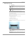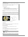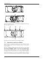
1
Orthopantomograph®
OP100 D
Orthoceph®
OC100 D
Upgrade Manual
12/2002
64504-4AC
Copyright
© 2002 by Instrumentarium Imaging
Documentation, trademark and the software are copyrighted with all rights
reserved. Under the copyright laws the documentation may not be copied,
photocopied, reproduced, translated, or reduced to any electronic medium or
machine readable form in whole or part, without the prior written permission
of Instrumentarium Imaging.
Orthopantomograph® and Orthoceph® are registered trademarks of
Instrumentarium Corporation. U.S. patents 4,641,336; 5,016,264; 5,425,065
and 5,444,754. German patent 4,344,745. Orthopantomograph® OP100 D and
Orthoceph® OC100 D comply with UL and C-UL (File E218408). Windows®
is trademark of Microsoft Corporation in the United States of America and
other countries. Pentium® is a registrated trademark of Intel Corporation.
Iomega® Jaz® is a registered trademark of Iomega Corp.
The original language of this manual is English.
Instrumentarium Imaging reserves the right to revise this publication from
time to time and to make changes in the content of it without obligation to
notify any person of such revision or changes.
Manufactured by
Instrumentarium Imaging
P.O. Box 20
FIN-04301 Tuusula
FINLAND
Tel. +358 10 394 6500
Fax. +358 10 394 6501
E-mail: [email protected]
Internet: http://www.InstrumentariumImaging.com
Table of Contents
1
Introduction ........................................................................................................ 1
1.1
1.2
2
Preparing for OC100 D upgrade kit installation............................................. 3
2.1
2.2
2.3
2.4
2.5
2.6
2.7
2.8
2.9
2.10
2.11
2.12
2.13
2.14
2.15
3
Installing the terminal board.................................................................................. 21
Installing the camera power supply board............................................................. 21
Fastening the collimator ........................................................................................ 22
Installing the head support bracket........................................................................ 23
Connecting the main cable .................................................................................... 24
Installing the head support..................................................................................... 25
Installing the panoramic camera holder................................................................. 26
Adjusting the camera connectors........................................................................... 27
The main cable connections ............................................................................. 29
5.1
5.2
5.3
5.4
5.5
5.6
6
Unpacking the crate ............................................................................................... 13
Installing the arm angle ......................................................................................... 13
Assembling the cephalostat kit .............................................................................. 14
Installing the cephalostat kit .................................................................................. 16
Changing the transformer ...................................................................................... 16
Removing the cephalostat head cover ................................................................... 16
Removing the transport supports........................................................................... 17
Fastening the camera holder .................................................................................. 17
Connecting and disconnectiong the ccd camera.................................................... 18
Modification of the panoramic unit ................................................................ 21
4.1
4.2
4.3
4.4
4.5
4.6
4.7
4.8
5
Before starting ......................................................................................................... 3
Removing the tube head covers............................................................................... 3
Removing the head support assembly ..................................................................... 5
Removing the collimator ......................................................................................... 6
Opening the inverter board ...................................................................................... 6
Removing the cassette head..................................................................................... 7
Removing the covers of the carriage assembly ....................................................... 9
Removing the patient positioning panel .................................................................. 9
Removing the CPU................................................................................................ 10
Removing the interface board................................................................................ 10
Unplugging the connector X6................................................................................ 10
Disconnecting the main cable................................................................................ 11
Removing the head support bracket ...................................................................... 11
Changing the side box chassis l............................................................................. 11
Removing the film cephalostat .............................................................................. 12
Installing the cephalostat kit............................................................................ 13
3.1
3.2
3.3
3.4
3.5
3.6
3.7
3.8
3.9
4
General..................................................................................................................... 1
Contents of upgrade kits .......................................................................................... 2
Connecting the plug X6......................................................................................... 29
Connecting the interface board cables................................................................... 29
Connecting the power board cables....................................................................... 29
Connecting the cables in the left side box chassis................................................. 30
Connecting the cables to CPU ............................................................................... 30
Connecting the panels............................................................................................ 31
Permanent installation to mains voltage ........................................................ 33
64504-4AC
Instrumentarium Imaging
i
7
Adjusting the unit ............................................................................................. 35
7.1
7.2
7.3
Preparation............................................................................................................. 35
Adjusting the cephalostat arm ............................................................................... 36
Adjusting the panoramic collimator ...................................................................... 37
7.3.1 OP100 D Unit ..........................................................................................................37
7.3.2 OC100 D Units: .......................................................................................................38
7.4
Adjusting the cephalostat collimator ..................................................................... 40
7.5
7.6
7.7
7.8
7.9
7.10
7.11
Adjusting the secondary collimator....................................................................... 43
Test images ............................................................................................................ 45
Calibrating the detection sensitivity ...................................................................... 45
Calibrating the AEC .............................................................................................. 47
Ear rod alignment .................................................................................................. 47
Adjusting the laser light......................................................................................... 48
Calibrating the nasion frequency ........................................................................... 49
7.4.1 Cephalostat beam check and alignment ...................................................................42
8
Finishing the kit installation ............................................................................ 51
8.1
8.2
8.3
8.4
8.5
8.6
ii
Cephalostat covers ................................................................................................. 51
Tube head assembly covers ................................................................................... 51
Head support covers .............................................................................................. 52
Main support cover ................................................................................................ 52
Covers of the cabin ................................................................................................ 52
Replaced parts........................................................................................................ 53
Instrumentarium Imaging
64504-4AC
1 Introduction
1 Introduction
1.1
General
This manual covers the upgrading of the left handed OC100 unit to left
handed OC100 D unit. However all digital upgrades can be performed
according to this manual. The table below shows which chapters of this
manual must be gone through in a certain upgrade.
Original
model
OP100
(s/n 71000 and
up)
OP100
Upgraded
Relevant chapters
model
OP100 D with 2 - 2.14, 4 - 5.6, 6.1,
AEC
6.3, 7.2 - 7.5
OC100 D
2 - 2.14, 3 - 3.9, 4 7.5
OC100
OC100 D
All
OP100 D
OP100 D with 2 - 2.3, 2.5, 2.7, 2.8,
(up to s/n 78349)
AEC
2.9 - 2.14, 4.1, 4.4 4.6, 5 - 5.2, 5.5 - 5.6,
6.1, 7.2 - 7.5
OP100 D
OC100 D
2 - 2.14, 3 - 3.9, 4.1,
(up to s/n 78349)
4.4 - 4.6, 5 - 7.5
OP100 D
OC100 D
2.1, 2.7, 3 - 3.9, 5.4,
(s/n 78350 and
6 - 6.9, 7.1, 7.5
up)
Code of the kit
64443
65932
65932
AEC kit
63677
60069
64534
NOTE
Always check the latest kit codes from the price list before ordering.
Use only approved cables and plugs.
Mains connector types:
•
•
NEMA 6-15P or similar Hospital grade (US)
HBL8215C or similar Hospital grade (JAPAN)
Power supply cord:
•
•
64504-4AC
H05VV5-F / AWG 14 (UL2587)
H05VV-F3G 10-16A 250V (CE)
Instrumentarium Imaging
1
1 Introduction
1.2
Contents of upgrade kits
There is different kind of kits. Look at the paking list to see the contents of
the delivery.
2
Instrumentarium Imaging
64504-4AC
2 Preparing for OC100 D upgrade kit installation
2 Preparing for OC100 D upgrade kit installation
2.1
Before starting
The upgrading starts with removing the parts of the unit. Some may find this
easier if certain movements of the unit are been prevented. In order to keep
the unit stable in the beginning of the upgrading perform as follows: Switch
on the unit. Lift the cassette head up. Drive the carriage near to the lowest
position and screw the lock bolt behind the column.
If there appears problems to have access behind the column release the floor
mounting of the column, but leave the back center screw in place and loosen
the wall mount angle adjustment bracket. Turn the unit so that the operation is
possible.
2.2
Removing the tube head covers
Detach the lever knobs of the tube head. Unscrew the levers.
64504-4AC
Instrumentarium Imaging
3
2 Preparing for OC100 D upgrade kit installation
Remove the tube head covers.
Remove the top cover of the main support.
4
Instrumentarium Imaging
64504-4AC
2 Preparing for OC100 D upgrade kit installation
2.3
Removing the head support assembly
Remove the head guard and the rotating units lower cover.
Loosen the hair cover and then unscrew the heads positioning bracket.
CAUTION
Hold the head positioning bracket after loosening the screws so that the cable
connector will not break down. Disconnect the plug X50 and put the head
positioning bracket aside.
Disconnect the plug X49 and loosen the head support linear movement.
NOTE
Do not let the guides fall down from the head support linear movement after
removing it.
64504-4AC
Instrumentarium Imaging
5
2 Preparing for OC100 D upgrade kit installation
2.4
Removing the collimator
Panoramic collimator
Loosen the screws pointed in the picture below.
Cephalostat collimator
Loosen the screws of the collimator pointed in the pictures below. Slide the
collimator to get access to all screws. Remove the collimator.
NOTE
Do not drop the flange while removing the collimator.
2.5
Opening the inverter board
Let down the cassette head and switch off the unit.
WARNING
Before proceeding the upgrade, assure that the unit is switched off and
removed from the mains. Touching the inverter board of the unit being
running may cause an electric shock.
6
Instrumentarium Imaging
64504-4AC
2 Preparing for OC100 D upgrade kit installation
Loosen the screws on the side of the tube head. Open the inverter board and
leave it hanging on the tube head.
Remove the main cable clamp and disconnect the following plugs:
X30, X31, X32, X33, X34.
2.6
Removing the cassette head
NOTE
If upgrading from OP100 D (serial number up to 78349) the panoramic
camera is fixed. If desired to upgrade the camera to detachable one remove
the camera and use the upgrade parts. Then also go through the chapter
“Installing the panoramic camera holder”.
Disconnect the cables of the cassette head inside the rotating unit and remove
the cable holders. After removing the holders screw back the screws of the
cable holders for the cephalostat terminal board.
Loosen the screws on the top of the cassette rack head. Then remove the
screws of the secondary plate.
64504-4AC
Instrumentarium Imaging
7
2 Preparing for OC100 D upgrade kit installation
NOTE
Hold the secondary plate while unscrewing so that the plate does not fall
down.
Loosen the bolts holding the cassette head and let it down carefully.
8
Instrumentarium Imaging
64504-4AC
2 Preparing for OC100 D upgrade kit installation
2.7
Removing the covers of the carriage assembly
NOTE
If upgrading OP100 D units with serial number 78350 and up perform only
the sections 1-2.
1
Remove the carriage top plate.
2
Loosen the screw holding the side box cover on both sides of the unit
and open the covers.
3
Remove the carriage upper trim cover.
4
Loosen the screws of the mirror cover and remove the mirror cover.
2.8
Removing the patient positioning panel
NOTE
If upgrading OP100 D units the patient positionig panel is not changed. In
that case only disconnect the cables.
Remove the bottom trim cover a and the carriage lover trim cover b.
64504-4AC
Instrumentarium Imaging
9
2 Preparing for OC100 D upgrade kit installation
Remove the cables from the patient positioning panel c and loosen the nuts of
it. Remove the panel.
2.9
Removing the CPU
Disconnect the plug X16 from the interface board.
Disconnect the following plugs on the CPU board:
X2, X3, X7, X1, (X12, only in digital units), X8, X6, X4, X9.
Unscrew all the nuts of the CPU and remove the CPU board. Repeat this for
the CPU static shield. Note the routing of the cables under the CPU board for
the later couplings.
2.10
Removing the interface board
Disconnect the following plugs from the interface board:
X111, X17, X15, X19, X20
Unscrew the plastic nuts and remove the interface board.
2.11
Unplugging the connector X6
Unplug the following four wires from the connector X6:
blue
brown
10
Red White
Gray
blue
green
yellow
gray
Instrumentarium Imaging
violet
black
64504-4AC
2 Preparing for OC100 D upgrade kit installation
Fig 2.1. Connector X6
2.12
Disconnecting the main cable
Disconnect the main cable´s ground cable below the lower shelf assembly.
Lift up the main cable above the main support assembly. Disconnect the plug
X109.
Disconnect the following plugs from the power board:
X28, X14, X27, X26.
2.13
Removing the head support bracket
Loosen the screws on the support
(1.). Rotate the flywheel (2.)
clockwise so that the head support
bracket is in the farthest position
from the column. Lift the head
support bracket (3.) from the main
support assembly.
2.14
Changing the side box chassis l
Remove the Side box cover L from the left side of the unit. Then loosen the
screws holding the side box chassis. Replace the side box chassis L with the
new one and tighten with the screws.
64504-4AC
Instrumentarium Imaging
11
2 Preparing for OC100 D upgrade kit installation
2.15
Removing the film cephalostat
CAUTION
This step requires two service persons.
Remove the cephalostat arm assembly by loosening the bolts behind the
column. Prior to loosening ask another service person to hold the arm
assembly.
12
Instrumentarium Imaging
64504-4AC
3 Installing the cephalostat kit
3 Installing the cephalostat kit
This manual covers the installation of the left handed OC100 D unit.
However right-handed unit installation is similar otherwise the exception is
mentioned.
3.1
Unpacking the crate
Lift up the outer part of the polystyrene box pressing at the same time the
ceph head then lift the cephalostat head from the crate. Note the location of
the CCD camera.
CAUTION
The camera must not be dropped or exposed to impacts.
3.2
Installing the arm angle
If the unit is mounted on the base plate fasten the cephalostat support prior to
installing the cephalostat arm.
64504-4AC
Instrumentarium Imaging
13
3 Installing the cephalostat kit
Install the cephalostat arm angle to the carriage.
NOTE
The four bolts in the middle of the arm angle are for mounting. The rest of the
bolts are for adjusting the arm.
Fasten the support piece to the carriage.
3.3
Assembling the cephalostat kit
Route the cables through the arm angle. Note the right hole.
NOTE
The U-shaped external piece is assembled only in the right-handed
cephalostat. Shown below.
14
Instrumentarium Imaging
64504-4AC
3 Installing the cephalostat kit
Tighten the arm angle to the cephalostat head. Attach the cover.
Route the cables trough the cephalostat arm. Tighten the cephalostat
arm to the arm angle. The mounting holes of the arm are closer to
each other at the cephalostat head
end than at the column end.
64504-4AC
Instrumentarium Imaging
15
3 Installing the cephalostat kit
3.4
Installing the cephalostat kit
CAUTION
This step requires two service persons.
Lift the cephalostat assembly to the column. Take care that the cable goes in
the cavity of the arm angle. Tighten the scerws.
Attach the cables to the side box chassis.
3.5
Changing the transformer
Undo the couplings shown in the image below and remove the transformer.
Replace it with the new one.
3.6
Removing the cephalostat head cover
Loosen the screw next to the ceph arm angle and the screws below the control
panel. Then loosen the screw under the control panel. Remove the cephalostat
head cover.
16
Instrumentarium Imaging
64504-4AC
3 Installing the cephalostat kit
3.7
Removing the transport supports
Remove the ear holder, CCD camera and secondary collimator transport
supports below the cephalostat head.
NOTE
Take care that the transport supports do not fall while removing.
3.8
Fastening the camera holder
Attach first the camera holder cover. Then tighten the screws holding the
camera holder on the cephalostat head.
Fasten the cover to the camera holder with the screws. Rotate the green
handle to have an access to all screws.
64504-4AC
Instrumentarium Imaging
17
3 Installing the cephalostat kit
3.9
Connecting and disconnectiong the ccd camera
OC100 D unit can be equipped with 1 or 2 cameras. If the unit is equipped
with 1 cephalostat camera the same camera can be used for pan and ceph
imaging. Another possibility is to use 2 cameras at the place all the time. In
this case the unit is equipped with 1 pan and 1 ceph camera.
Panoramic camera
To remove the CCD camera from rotating unit press the knob downwards
(Figure 1). Push slightly the camera from below (Figure 2) so that it comes
off from the top. Lift the camera a little and pull it away (Figure 3).
To install the camera back to the rotating unit proceed as stated above in
reverse order.
Cephalostat camera
To remove the CCD camera from the cephalostat head press the knob on the
handle and turn it 360 degrees counter-clockwise (Figure 1). Press the clips
on the both sides of the camera (Figure 2) and lower the camera.
CAUTION
Hold the camera while pressing the clips in order that the camera won´t fall.
18
Instrumentarium Imaging
64504-4AC
3 Installing the cephalostat kit
To install the camera back to the cephalostat head lift the camera to holder
until a click is heard. Then press the knob on the handle and turn it 360
degrees clockwise.
CAUTION
The camera must not be dropped or exposed to impacts.
64504-4AC
Instrumentarium Imaging
19
3 Installing the cephalostat kit
20
Instrumentarium Imaging
64504-4AC
4 Modification of the panoramic unit
4 Modification of the panoramic unit
4.1
Installing the terminal board
Install the terminal board to the rotating unit so that the holes in the shield
plate (b.) remain under the screws (a.). Finally tighten the screws.
NOTE
If the unit contains fixed camera assembly system and the unit contains AEC
system, set jumper to pins J1. If the unit contains removable camera, leave the
pins J1 open.
NOTE
OPD terminal boards in the units up to the serial number 78350 (except s/n
78272) are not valid for OC100 D units or OP100 D units with AEC. When
upgrading to such unit the terminal board (60247) and cable C63 (69084)
must be changed to new ones.
4.2
Installing the camera power supply board
Loosen the screws of the spring bracket (1.) so that you can push the holder
plate between the bracket and the cast (2.). Screw one Allen screw (3 a) to the
cast projection (3 b). Screw one plastic M4 nut to the Allen screw so that
there is one plastic M4 nut between the cast and the holder plate.
Tighten the holder plate with the plastic M4 nut (4.) and the screws of the
spring bracket. Place the power supply board in place (5.) and tighten it with
the plastic nuts.
64504-4AC
Instrumentarium Imaging
21
4 Modification of the panoramic unit
4.3
Fastening the collimator
PANORAMIC COLLIMATOR
Fasten the collimator by tightening the screws pointed in the picture below.
CEPHALOSTAT COLLIMATOR
Fasten the collimator in reverse order you removed the film cephalostat
collimator.
22
Instrumentarium Imaging
64504-4AC
4 Modification of the panoramic unit
NOTE
Use the washers only with the two upper screws for cephalostat collimator
Prior installation remove the limiting plate on the right side of the collimator
(the image below).
4.4
Installing the head support bracket
Route the main cable through the hole of the main support assembly. Remove
the support plate and place the head support bracket on the main support
assembly.
CAUTION
Do not bend or twist the fibre optical cable.
Adjust the bracket in the middle of the main support (direction a).
64504-4AC
Instrumentarium Imaging
23
4 Modification of the panoramic unit
By rotating the fly wheel of the linear motor move the head support bracket to
the both ends and check that it does not touch the sliding plate. If needed
adjust the bracket in direction b.
Tighten the screws lightly. The screws are tightened finally after the head
support has been installed.
4.5
Connecting the main cable
Fasten the support plate to the head support bracket and fasten the main cable
to the spring bracket with the plastic cable clamp (code 63836).
Make the following connections:
Plug number
Where to
X64
X112
Fibre optic cables
Panoramic terminal board
X71 *
X72
X63 *
Camera power supply board
X73 *
Panoramic terminal board
X113 **
Collimator
X30
X31
X32
X33*
X34 *
Inverter board
24
Instrumentarium Imaging
64504-4AC
4 Modification of the panoramic unit
Plug number
Where to
X35 *
X36 *
X37 *
X38
Filament board
Ground cable
Tube head
*Separate cables
**Bind the cable to the tube head with the cable clamp.
Fig 4.1. The ground cable of the tube head
NOTE
The plugs X114 and X134 remains open under the rotating unit.
Rotate the rotating unit by hand and assure that any of the cables are not
pinched or stressed.
4.6
Installing the head support
Fasten the head support linear movement to the support plate. Remember to
install the plastic washer on left side to limit the movement of the sliding
chassis.
Adjust the guides so that the head support linear movement goes smoothly
back and forth and there is no slack.
64504-4AC
Instrumentarium Imaging
25
4 Modification of the panoramic unit
Connect the plug X49 to the head support bracket. Lift the hair cover and the
head positioning bracket close to the head support bracket and connect the
plug X50 and secure it with the clamp. Tighten the screws.
Slide the head positioning bracket back and forth. Assure that the head
positioning bracket does not make contact with the hair cover. If needed the
head support bracket can be adjusted sideways (see chapter Installing the
head support bracket). Finally tighten firmly the screws of the head support
bracket.
4.7
Installing the panoramic camera holder
Fasten with two bolts the camera holder to the rotaing unit. Connect the plug
X62 to the terminal board.
26
Instrumentarium Imaging
64504-4AC
4 Modification of the panoramic unit
4.8
Adjusting the camera connectors
The connector has been left slack in the factory to allow adjustment. Place the
CCD camera into the holder according to the chapter “CCD camera” and
check that the connectors of the holder and the camera fit together.
If the CCD camera does not fit to the holder, remove the holder from the unit
and adjust the circuitboard connector from the back side of the camera
holder. There is two screws holding the circuitboard which positions the
connector.
If it seems that the CCD camera does not fit to the circuitboard connector,
loosen both screws at the back side of the connector and place the CCD
camera in to the holder. Tighten both screws at the back of the connector.
64504-4AC
Instrumentarium Imaging
27
4 Modification of the panoramic unit
If it seems that the knob in the middle of the camera holder does not
match with the CCD camera, the camera support at the underedge can
be adjusted. Loosen the screws which connect the camera support to the
camera holder. Place the CCD camera to the camera holder and tighten the
screws.
28
Instrumentarium Imaging
64504-4AC
5 The main cable connections
5 The main cable connections
5.1
Connecting the plug X6
Plug the following wires to the connector X6 of the new main cable.
red
5.2
White blue
Red white blue
Green gray violet
yellow brown black gray yellow Blue
black
Connecting the interface board cables
Connect first the plug X109. Low down the main cable. Put the interface
board in place. Connect the following plugs to the interface board:
X111, X17, X19, X20, X15, X18.
5.3
Connecting the power board cables
NOTE
If upgrading the unit to OP100 D with AEC, connect the plugs X28, X14,
X27 and X26 as they originally were.
FOR OC100 D UNITS:
Connect the plug X27 of the separate cable to the power suppy board.
Connect the following plugs of the main cable to the power supply board:
X26, X27.
Route the plug X237/1 to the left side of the unit and the plug X2 to the CPU
board.
NOTE
The plugs X14 and X28 remains open.
Fix the cooling plate on the D5 on power supply board. You may have to
remove the component prior to fixing the cooler on it.
64504-4AC
Instrumentarium Imaging
29
5 The main cable connections
5.4
Connecting the cables in the left side box chassis
Connect one fibre optic cable plug of the main cable to the connector of the
side box chassis. Then connect one fibre optic cable plug of the ceph cable to
the other connector of the side box chassis. These two plugs can be connected
to the side box chassis connector in any order. Finally connect the remained
two plugs together.
Connect the following plugs of the ceph cable:
X106, X236/1, X236/2, X271/1, ground cable.
Make sure there is no paint between the ground connector and the side box
chassis. If needed erase the paint to enable the connection of the ground
cable.
5.5
Connecting the cables to CPU
Arrange the cables in the chassis and place the CPU statistic plate on top of
the plastic pillar screws. Fasten the plate with the other pillar screws.
Attach the CPU board in place. Route the flat cable from the CPU to the
interface board and plug the connector X16.
Connect the following plugs to CPU board:
30
Instrumentarium Imaging
64504-4AC
5 The main cable connections
X2, X3, X7, X1, X12, X8, X6, X4, X9
NOTE
Remember to route the two cables through the ferrite rings.
Tighten the cables X118L and X118R to the CPU´s pillar screws.
5.6
Connecting the panels
NOTE
If you are upgrading film unit to digital unit, replace the patient positioning
panel and select the user side. If you are upgrading digital unit select the user
side only.
Place the patient positioning panel to the lower shelf and fasten it with the
nuts (a). Connect the cable from the CPU to the connectors (b) X48/L and
X47/L (the cables X48/R and X47/R for right handed units).
Replace the control panel with the new one if upgrading film unit.
64504-4AC
Instrumentarium Imaging
31
5 The main cable connections
32
Instrumentarium Imaging
64504-4AC
6 Permanent installation to mains voltage
6 Permanent installation to mains voltage
OP100D and OC100D can be installed permanently to mains voltage.
Normally the unit is installed non-permanently with power supply cord and
mains plug. Electric current passes trough the both mains fuses (F1 and F2).
Permanently installed unit is connected straight to the branch circuit and so
that electric current passes trough only one mains fuse (F1).
WARNING
Only a qualified technician is permitted to carry out these connections.
Disconnect the main cable from the mains.
Remove the plug from the main cable.
Remove the blue cord from the right side of the fuse F2.
Remove the connector from the left side of the fuse F2 and connect the free
blue cable to the cable connector.
Fig 6.1. Circuit diagram 1. Cable connections in non-permanently installed unit.
Connect the removed blue cable to right side of the fuse F2 next to the leftsided blue cable.
64504-4AC
Instrumentarium Imaging
33
6 Permanent installation to mains voltage
Fig 6.2. Circuit diagram 2. Cable connection in permanently installed unit.
Use only approved cables.
Power supply cords type:
H05VV5-F3G 10-16A 250V (CE) or similar and for UL-countries
SJT, SJTO, SJO, ST, SO or STO AWG 14x3.
34
Instrumentarium Imaging
64504-4AC
7 Adjusting the unit
7 Adjusting the unit
7.1
Preparation
NOTE
Install CliniView software now. Refer to Installation Manual for the
CliniView software.
NOTE
Dim the room and unit lights when using the fluorecent tool.
Remove the locking bolt behind the carriage. Fasten the left door. Fasten the
new control panel. Fasten the inverter board. Switch on the unit. Make
rotation and linear movement tests.
Withdraw from use the old TMJ pointer (white) and the fluorescent tool with
magnet and replace with the new ones.
Check the position of the jumper X15 on the CPU board:
L = cephalostat on the left side
R = cephalostat on the right side
CHECKING THE COUNTER WEIGHTS
Lift the carriage to the uppest position and open the cover on the back side of
the column.
WARNING
There is a cutting hazard when the carriage is lifted up and the cover is
removed. Before operating with the weights bind the carriage so that it cannot
be lowered down.
64504-4AC
Instrumentarium Imaging
35
7 Adjusting the unit
Screw two bolts (M8) into the column back support. Fasten the strong cord
going over the wall mount bracket to the bolts.
Check the trim weights:
Unit model
Counter weights
OP100 D
3 small weights
4 large weights
OC100 D
1 small weight
22 large weights
Steel plate with plastic guides
Drive the carriage assembly up and down and check the balance. At the end
close the cover.
7.2
Adjusting the cephalostat arm
Check with a level that the ceph arm and the ceph head are in horizontal
position.
To adjust the ceph head twist the bolts C. In the example the two upper bolts
have been tightened and so obtained a small tilt.
36
Instrumentarium Imaging
64504-4AC
7 Adjusting the unit
To adjust the cephalostat arm loosen a
little the bolts A on the arm angle.
Then twist the bolt B and at the same
time help by hand the arm to move up
until the ceph arm is horizontal.
Finally tighten firmly the bolts A.
7.3
Adjusting the panoramic collimator
This section is divided into two parts. Section 6.3.1 is only for the basic
panoramic unit and section 6.3.2 is only for the cephalostat unit.
7.3.1
OP100 D Unit
NOTE
The beam is recommended to align first approximately with the fluorescent
tool. After that the accurate alignment is easiest to do with CliniView
software.
Select the panoramic collimator from the tube head. To stop the rotation
movement set “Pr 68 InS” to “EPS”. Go to the User programming mode.
Select program “Pr 68 InS” and press “OK”. Select the exposure without
movement option “EPS” and press “OK”. Exit programming without
switching the power off. See the OP100 D User Program Manual for details.
Attach the fluorescent tool in front of the panoramic camera or prepare
CliniView for the panoramic image capturing (refer to Installation Manual
and User Manual for the CliniView software.). Make an exposure and verify
that the beam is vertical and in the middle of the tool / screen´s image.
Fig 7.1. Beam alignment tool in panoramic camera head
64504-4AC
Instrumentarium Imaging
37
7 Adjusting the unit
If needed adjust the beam from the collimator according to instructions
coming later in this chapter.
From the control panel select Program P1 (Standard Panoramic Procedure),
Manual mode “M” and 73kV / 5mA and 0.1s values.
Computer preparation:
•
•
•
•
Switch on PC.
Start Windows 2000 software.
Start the CliniView software. Refer to the “User Manual for CliniView
Software” to get instructions how to use the Cliniview software.
Press “Start image captruring” button to get ready for an exposure.
Make an exposure and note the location of the beam from the image on the
PC display.
The center line of the beam should be vertical and the beam should be
centered. Note that the beam is V-shaped: lower end of the beam is narrower.
You can use software measurement tool and zoom feature to check that the
beam alignment is correct. Refer to the Installation Manual and User manual
for CliniView software. Check the beams vertical place by taking a normal
panoramic image with lowest values. Check that the empty area around the
image is equal in size.
If needed adjust the beam in the following order:
Twisted beam:
Loosen the collimator fixing screws (A) and turn the collimator until the
beam is vertical. Tighten the fixing screws (A).
Horizontal adjustment:
Turn the horizontal adjustment screw (B) until the beam is centered.
Vertical adjustment:
Turn the vertical adjustment screw (C) until the lower end of the beam is
(2± 0,7) mm above the lower frame of the image on the PC display.
7.3.2
OC100 D Units:
NOTE
The beam is recommended to align first approximately with the fluorescent
tool. After that the accurate alignment is easiest to do with CliniView
software.
38
Instrumentarium Imaging
64504-4AC
7 Adjusting the unit
Select the panoramic collimator from the tube head. To stop the rotation
movement set “Pr 68 InS” to “EPS”. Go to the User programming mode.
Select program “Pr 68 InS” and press “OK”. Select the exposure without
movement option “EPS” and press “OK”. Exit programming without
switching the power off. See the OP100 D User Program Manual for details.
Attach the fluorescent tool in front of the panoramic camera or prepare
CliniView for the panoramic image capturing (refer to Installation Manual
and User Manual for CliniView). Make an exposure and verify that the beam
is vertical and in the middle of the tool / screen´s image.
Fig 7.2. Beam alignment tool in panoramic camera head
From the control panel select Program P1 (Standard Panoramic Procedure),
Manual mode “M” and 73kV / 5mA and 0.1s values.
Computer preparation:
•
•
•
•
Switch on PC.
Start Windows 2000 software.
Start the CliniView software. Refer to the “User Manual for CliniView
Software” to get instructions how to use the Cliniview software.
Press “Start image capturing” button to get ready for an exposure.
Make an exposure and note the location of the beam from the image on the
PC display.
The center line of the beam should be vertical and the beam should be
centered. Note that the beam is V-shaped: lower end of the beam is narrower.
You can use software measurement tool and zoom feature to check that the
beam alignment is correct. Refer to the Installation Manual and User manual
for CliniView software. Check the beams vertical place by taking a normal
panoramic image with lowest values. Check that the empty area around the
image is equal in size.
To adjust tilt of the collimator, loosen the screws indicated in the images
below. Slide the collimator to have an access to all screws. Twist the
collimator to adjust the beam vertically.
64504-4AC
Instrumentarium Imaging
39
7 Adjusting the unit
To move the collimator sideways loosen the 4 screws (A) and twist the screw
B. Finally tighten the 4 screws.
Screw C is for vertical adjustment of the panoramic slot plate.
7.4
Adjusting the cephalostat collimator
When selected the cephalostat collimator the beam should go by the
panoramic camera until it reaches the cephalostat camera. Check the beam
course as follows:
Select the cephalostat collimator from the tube head. To stop the rotation
movement set “Pr 68 InS” to “EPS”. Go to the User programming mode.
Select program “Pr 68 InS” and press “OK”. Select the exposure without
movement option “EPS” and press “OK”. Exit programming without
switching the power off. See the OP100 D User Program Manual for details.
Attach the fluorescent tool in front of the panoramic camera. Make an
exposure and verify that the beam passes the panoramic CCD camera without
40
Instrumentarium Imaging
64504-4AC
7 Adjusting the unit
hitting it however. Beam should be seen in the lower right corner of the
fluorecent tool.
Fig 7.3. Beam alignment tool in panoramic camera head
If the beam hits the CCD camera, adjust the collimator horizontally. Loosen
the two middlemost screws on the front side and adjust the course of the
beam from the screw on the left side. After adjustment tighten the screws on
the front side. Check that there is no rotational effect in the collimator after
adjustment.
Fig 7.4. Arrows point to the adjustment screws.
64504-4AC
Instrumentarium Imaging
41
7 Adjusting the unit
7.4.1
Cephalostat beam check and alignment
Detach both covers of the secondary collimator. Detach
the cable (a) connected to the secondary collimator.
Loosen the screws (b) and remove the secondary
collimator.
Attach the fluorecent tool to the cephalostat camera.
Check that the cephalostat collimator has been selected.
In sw. 1.4.13:
Select the program P6 and Pr68Ins, EPS and exposure
values 57kV/2mA. Drive movements in to the correct
position by pressing the patient positioning button. Press
the exposure button and observe the fluorescentic tool.
The beam should be in the middle of the tool.
In sw. 1.4.11:
Press OK for a while to get to User Program Mode. Select the program
“Pr68Ins” and choose “nCh” with the arrow keys. Exit the program by
pressing OK and select the program 6 (P6). Select the Test mode and press
the exposure button when the unit drives to the beam alignment check
position.
Press OK for a while to get to User Program Mode. Select the program
“Pr68Ins” and choose “EPS” with the arrow keys. Exit the program by
pressing OK.
Press the exposure button and observe the fluorescent tool. The beam should
be in the middle of the tool.
Fig 7.5. Beam alignment tool in cephalostat camera head
In case the beam is not in the middle of the tool follow the ensuing
instructions.
1
42
First make the rough adjustment for the angle from ceph arm connection
point.
Instrumentarium Imaging
64504-4AC
7 Adjusting the unit
2
After observing the beam in the alignment tool make the fine tuning by
rotating the code disk on the rotating unit. Loosen the screws and rotate
the disk slightly. If needed turn the linear movement motor to have
access to both code disk screws.
The second microswitch (see image below) from the left affects to this
rotating movement.
NOTE
Rotate the code disk only slightly.
The beam too much right
The beam too much left
Rotate code disc clockwise
Rotate code disc counterclockwise
Repeat the beam alignment test.
7.5
Adjusting the secondary collimator
Attach the secondary collimator vertically in place and connect the cable.
Check that edges of secondary collimator and CCD sensor are vertically
parallel, as in picture beside.
Drive the unit to the centre position. Select the program P6 and Pr68Ins, EPS
and exposure values 57kV/2mA/0.2s. Drive movements in to the correct
position by pressing the patient positioning button.
NOTE
In the older sw. 1.4.11 select the nCh in PR 68 Ins, go to the lateral imaging
program P6 and select Test mode. Then press the exposure button until
movement stops, then release exposure button. Go back to the PR 68 Ins and
choose EPS mode.
64504-4AC
Instrumentarium Imaging
43
7 Adjusting the unit
Start CliniView and click the “Start image capturing session” button. Take an
exposure. White unexposed area must not be visible on the screen in any
place.To adjust tilt loosen the screw a and tighten the opposite screw a on the
other side as needed.If needed adjust the secondary collimator vertically by
loosening the screws (b) and adjusting the screw (c) on the top of the
secondary collimator.
To adjust the secondary collimator horizontally, loosen the screw shown in
the picture below. There is one hole in the frame. Guide a flat screwdriver
trough the hole against the end of the threaded rod. Hold with your hand the
toothed wheel and the same time turn with the screwdriver the threaded rod.
Select the lateral projection program (P6) and make an exposure. Observe the
led lights on the board on the secondary slot. The middle one should
illuminate during the entire exposure.
44
Instrumentarium Imaging
64504-4AC
7 Adjusting the unit
NOTE
The secondary collimator has been adjusted horizontally in the factory and it
is rare that this adjustment has to be done during the upgrade/installation.
7.6
Test images
Make an cephalometric exposures and check that the exposed area is within
the image window. There should be a narrow white area all around the
exposure of the beam. If necessary, adjust the secondary collimator vertically
to adjuts the height of the beam. If there still is a broblem witht he beam
alignment, correct the tilt of the ceph head and repeat the whole OCD beam
alignment procedure.
7.7
Calibrating the detection sensitivity
Priorotize the factory settings, but
if needed adjust the channel
sensitivity from R10, R4 and R16.
These three trimmers effects to the
beam detection in ceph secondary
collimator. By turning trimmers
clockwise, the sensors are getting
more unsensitive. By turning the
trimmers counter clockwise, the
sensors are getting more sensitive.
Trimmers for
detection sensitivity
R4, R10, R16
For units with s/n 79974 or higer (Trimmers value 20K)
Turn trimmers R10, R4 and R16 counter clockwise to the minimum value.
To adjust the detection sensitivity, drive the unit to the centre position. Select
the program P6 and Pr68Ins, EPS and exposure values 57kV/2mA. Drive
movements in to the correct position by pressing the patient positioning
button.
NOTE
In the older sw. 1.4.11 select the nCh in PR 68 Ins, go to the lateral imaging
program P6 and select Test mode. Then press the exposure button until
movement stops, then release exposure button. Go back to the PR 68 Ins and
choose EPS mode.
Make an exposure and check that the middle channel barely detects the
radiation by illuminating the LED H2. LED:s H1 and H3 do not illuminate. If
needed, adjust with trimmer R10 clockwise.
Move the secondary collimator by screwing 10mm to the left from the centre
position. Then select the program Pr68Ins, EPS and exposure values 60kV/
2,5mA. Make an exposure and adjust the left channel trimmer R4 so that the
LED H1 barely illuminates.
64504-4AC
Instrumentarium Imaging
45
7 Adjusting the unit
Move the secondary collimator 10 mm to the right from the center position.
Then select the program Pr68Ins, EPS and exposure values 60kV/2,5mA.
Make an exposure and adjust the right channel trimmer R16 so that the LED
H3 barely illumintes.
Take ceph image with maximum exposure values. Neither H1 nor H3 is
allowed to illuminate at the same time with H2 (In the beginnign of
exposure).
Take a ceph image without radiation. LED:s H1, H2 and H3 are not allowed
to illuminate.
For units with s/n up to 79973 (Trimmers value 1K)
Turn trimmers R10, R4 and R16 clockwise to the maximum value.
To adjust the detection sensitivity, drive the unit to the centre position. Select
the program P6 and Pr68Ins, EPS and exposure values 57kV/2mA. Drive
movements in to the correct position by pressing the patient positioning
button.
NOTE
In the older sw. 1.4.11 select the nCh in PR 68 Ins, go to the lateral imaging
program P6 and select Test mode. Then press the exposure button until
movement stops, then release exposure button. Go back to the PR 68 Ins and
choose EPS mode.
Make an exposure and check that the middle channel barely detects the
radiation by illuminating the LED H2. LED:s H1 and H3 do not illuminate. If
needed, adjust with trimmer R10 counter clockwise.
Move the secondary collimator by screwing 10mm to the left from the centre
position. Then select the program Pr68Ins, EPS and exposure values 60kV/
2,5mA. Make an exposure and adjust the left channel trimmer R4 so that the
LED H1 barely illuminates.
Move the secondary collimator 10 mm to the right from the center position.
Then select the program Pr68Ins, EPS and exposure values 60kV/2,5mA.
Make an exposure and adjust the right channel trimmer R16 so that the LED
H3 barely illumintes.
Take ceph image with maximum exposure values. Only H1 or H3 is allowed
to illuminate at the same time with H2 (In the beginnign of exposure).
Take a ceph image without radiation. LED:s H1, H2 and H3 are not allowed
to illuminate.
46
Instrumentarium Imaging
64504-4AC
7 Adjusting the unit
7.8
Calibrating the AEC
Open the CliniView program and activate the image aquisation by pressing
“Start image capturing” button. Calibrate the Automatic Exposure Control
(AEC) after adjusting the unit. Attach (with tape e.g.) the Al calibration tool
in front of the tube head panoramic collimator. Select the program Pr68Ins,
FrE and exposure values 73kV/12mA. The exposure time should be increased
by pushing the right arrow key so that the frequency can be read more easily
(Exposure time longer). Adjust the gain trimmer (R10) on the Pan AEC
terminal board so that the time display shows 144kHz (± 3 kHz) during the
exposure.
CAUTION
When ever checking the AEC frequency, the optical link condition has to be
OK. (Optical wires connected and PC powered on.)
7.9
Ear rod alignment
Fasten the ear rods with the screws.
Ear holder center pins and the focus must be aligned on the same line. The
procedure is as follows:
Turn the ear rods on the lateral view position. Make the exposure.
Both ear pin holders have a small metal pin and circle that will be seen on the
image: the rings and pins on the image should be exposed within each other.
Larger ring represents the tube side, and smaller ring the CCD camera side.
If the pins cross each other, the alignment must be done.
HORISONTAL ADJUSTMENT
64504-4AC
Instrumentarium Imaging
47
7 Adjusting the unit
Loosen the 4 locking screws (A) on the ear holder assembly.
NOTE
There is only one point from where the screws can be twisted. Rotate the ear
holder assembly to have an access to all locking screws.
Adjust with the eccentric cam screw (B). The amount of rotation can be seen
on the scale after marking the starting position.
VERTICAL ADJUSTMENT
Loosen the 4 locking screws (C) from sides of the ear holder assy. Adjust
with the screw (D) at the end of the ear holder assy. The amount of the
vertical movement can be seen on the scale after marking the starting
position.
Make the exposure and re-align, if necessary.
7.10
Adjusting the laser light
Adjust the laser light so that the beam goes horizontally through the both ear
rods.
48
Instrumentarium Imaging
64504-4AC
7 Adjusting the unit
There is a special tool (code 68719) for laser light alignment. This tool needs
to be ordered separately.
7.11
Calibrating the nasion frequency
Connect the frequency meter to the ceph terminal board test points TP52
(NASIO FRQ) (a) and TP60 (GND) (b). Slide the nasion support to the
furthest position from the ear rods. Adjust with the trimmer R109 (c) the
reading of the frequency meter to 4000 Hz (±25 Hz). Slide the nasion support
to the closest position to the ear rods. Adjust with the trimmer R146 (d) the
reading of the frequency meter to 2000 Hz (±25 Hz). Check the readings
again and repeat the adjusting if needed.
64504-4AC
Instrumentarium Imaging
49
7 Adjusting the unit
50
Instrumentarium Imaging
64504-4AC
8 Finishing the kit installation
8 Finishing the kit installation
8.1
Cephalostat covers
Fasten the ceph head cover and the ceph head control panel.
Fasten the covers of the secondary collimator. Attach first the white cover and
tighten it with the 4 screws. Then place the gray cover against the white one,
lift it upwards and tighten the screw on the bottom of the secondary
collimator.
8.2
Tube head assembly covers
Fasten the covers of the tube head assembly. The tube head assembly front
cover´s color is gray in digital units.
64504-4AC
Instrumentarium Imaging
51
8 Finishing the kit installation
8.3
Head support covers
Replace the rotating unit lower cover and the head guard. The color of the
new covers is gray.
8.4
Main support cover
Replace the main support cover.
8.5
Covers of the cabin
NOTE
If upgrading OP100 D units with serial number 78350 and up perform only
the sections 3-4.
Switch on the unit and check that the midsagittal light is centered to the head
support. If needed adjust the light according to the Installation and
adjustments manual. If ok switch off the unit.
52
Instrumentarium Imaging
64504-4AC
8 Finishing the kit installation
Fasten the mirror cover (1.), carriage upper trim cover (2.), side box covers
on both sides of the unit (3.) and the carriage top plate (4.).
Fasten the bottom trim cover a to the lower desk. Connect the ground cable to
the carriage lover trim cover b and fasten it to the carriage.
Fasten the knobs for the levers of the tube head and the midsagittal light.
8.6
Replaced parts
After the upgrade many parts remain useless and some of these include nonenvironmental friendly substances. Follow the local regulations on disposal
of the following items:
– The fluorescent tool
– Counter weights
– Circuit boards
64504-4AC
Instrumentarium Imaging
53
8 Finishing the kit installation
NOTES:
54
Instrumentarium Imaging
64504-4AC
Instrumentarium Imaging Italia S.R.L.
Via Cassanese, 100
20090 Segrate (MI), Italy
Tel. +39 02 21 30 28 1 · Fax +39 02 21 30 28 60
[email protected]
Instrumentarium Imaging is constantly improving its products and reserves the right to
change these specifications without notice.
www.InstrumentariumImaging.com
Instrumentarium Imaging Singapore
152 Beach Road
#12-03A Gateway East
189721 Singapore
Tel. +65 6391 8600 · Fax +65 6396 3009
[email protected]
Instrumentarium Imaging Dental GmbH
P.O.Box 2044, 77680 Kehl am Rhein, Germany
Tel. +49 7851 932 90 · Fax +49 7851 932 930
[email protected]
Distributor:
12/2002 © Instrumentarium Imaging
Instrumentarium Imaging Inc.
300 West Edgerton Avenue, Milwaukee
Wisconsin 53207, USA
Tel. +1 800 558 6120, +1 414 747 1030
Fax +1 414 481 8665
[email protected]
Instrumentarium Imaging France S.A.R.L.
4, Avenue des Roses
94386 Bonneuil Sur Marne Cedex, France
Tel. +33 1 43 39 51 51 · Fax +33 1 43 39 75 75
[email protected]
64504-4AC
Instrumentarium Imaging
P.O.Box 20, FIN-04301 Tuusula, Finland
Tel. +358 10 394 6500 · Fax +358 10 394 6501
[email protected]