1
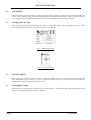
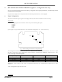
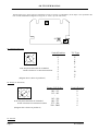
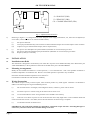
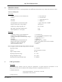
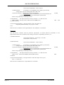
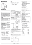
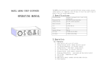
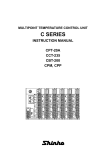
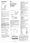
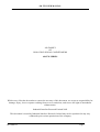
420 TW USER MANUAL
420 FAMILY
OF
ISOLATING SIGNAL CONDITIONERS
420 TW SERIES
Whilst every effort has been taken to ensure the accuracy of this document, we accept no responsibility for
damage, injury, loss or expense resulting from errors or omissions, and reserve the right of amendment
without notice.
Industrial Interface Research Limited 2002
This document is issued by Industrial Interface Research Ltd and may not be reproduced in any way
without the prior written permission of the company
IIG-9604-02
Page 1
420 TW USER MANUAL
CONTENTS
Page 2
1.0
INTRODUCTION
3
2.0
UNPACKING
5
3.0
CONNECTIONS
6
4.0
RECONFIGURATION (applies
to reconfigurable option units
only)
7
5.0
RECALIBRATION
10
6.0
INSTALLATION
12
7.0
SPECIFICATIONS
13
IIG-9604-02
420 TW USER MANUAL
1.0
INTRODUCTION
The 420 TW series is a family of isolated two wire 4 - 20 mA transmitters capable of
accepting
electrical input types and operating with an output loop voltage of 12 to
32 V DC.
a
variety
of
The input signal is the only parameter required to define any unit exactly. This information,
together
with
a
unique serial number, is printed on the side label of each unit; records of the
exact configuration of every product
shipped are maintained at the factory.
1.1
Input Types and Ranges
420 TW - HL (Previously designated 420 TW - 0 / 420 TW - 1)
Accepts either voltage or current (i.e. high level) inputs. The standard default configuration of the unit allows 4 - 20
mA, 0 - 20 mA, 2 - 10 V or 0 - 10 V inputs to be reconfigured by the user. However a much wider range of inputs is
available to order.
In general the limits on signals that can be handled with the accuracy specified in Section 7 are:
Input Types
DC Current
DC Voltage
Input range MIN
0 - 100µA
0 - 100mV
Input range MAX
0-5A
0 - 100 V
AC Current
AC Voltage
0 - 200µA RMS
0 - 200mV RMS
0 - 5 A RMS
0 - 70 V RMS
Notes
Use 420 TW-TC for V in
< 100mV
45HZ ≤ f in
45HZ ≤ f in
Standard process ranges such as 0 - 5 V or 1 - 5 V are of course covered.
420 TW - TC (Previously designated 420 TW - 2)
Accepts inputs directly from the following thermocouple types: E,T,K,T,N,R,S,F. Temperature ranges from 0 - 100 oC
to 0 - 2000 oC can be reconfigured (mV outputs without cold junction compensation can be catered for to special
order). All specified ranges are 0 oC referred, although negative inputs will not damage the unit. Automatic cold
junction compensation is provided. Either upscale or downscale output drive, on sensor wire break detection, can be
selected. The output is not linearized. Although any thermocouple type can be selected for any temperature range, the
table below indicates the ranges for which the accuracy specified in section 7 is achieved:
INPUT TYPE
mV
J(L)
K
T(U)
E
N
R
S
F
IIG-9604-02
FULL SCALE INPUT
MIN
4mV
80oC
100 oC
95 oC
65 oC
150 oC
460 oC
480 oC
100 oC
NOTES
MAX
100mV
1200 oC
1372 oC
400 oC
1000 oC
1300 oC
1768 oC
1760 oC
1400 oC
Special order:CJC not fitted
Page 3
420 TW USER MANUAL
2.0
UNPACKING
Please inspect the instrument carefully for signs of shipping damage. The unit is packaged to give maximum protection
but we can not guarantee that undue mishandling will not have damaged the instrument. In the case of this unlikely
event, please contact your supplier immediately and retain the packaging for our subsequent inspection.
2.1
Checking the Unit Type
Each unit has a unique serial number label (fig.1 below) on which full details of the configuration are given. These
details should be checked to ensure conformance with your requirement.
Fig. 1 - Serial Number Label
Fig. 2 - Front Panel Label
3.0
CONNECTIONS
Before proceeding, please check the information on the serial number label on one side of the unit to ensure that the
unit configuration is correct (see Fig. 1 above). Connection details are given on the front panel label of the unit,
adjacent to the relevant connections (see Fig. 2 above).
3.1
Loop Supply Voltage
The voltage across the output loop terminals must not exceed 32V DC - otherwise damage to the instrument may result.
The unit is protected against reverse polarity connection.
Page 4
IIG-9604-02
420 TW USER MANUAL
4.0
RECONFIGURING THE INSTRUMENT (applies to reconfigurable units only)
In many cases the instrument will have been factory configured to the required specifications, and calibrated, in which
case this section can be ignored.
If a particular configuration is not specified then the default (specified below) will be supplied.
4.1
Input Configuration
This section details the steps required to reconfigure the unit, after which recalibration will be necessary.
420 TW-HL
Current or voltage input can be selected to achieve any of the following DC inputs:
0-20mA
4-20mA
0-10V
2-10V
(If the input is not specified at the time of order the default configuration of 4 - 20 mA will be set).
B2
B1
B3
Fig.3 - Solder Bridge Link Selection Of Input Range
To reconfigure the instrument remove the side cover without the serial number label from the unit - this cover is a push
fit and can be prised off with a thumb nail or small screwdriver. The three links B1,B2,B3, should be open or short
circuit according to the following table:
Input Range
0 - 20 mA
4 - 20 mA
0 - 10 V
2 - 10 V
B1
Short
Short
Open
Open
B2
Short
Short
Open
Open
B3
Short
Open
Short
Open
WARNING: TAKE GREAT CARE NOT TO DAMAGE THE DELICATE COMPONENTS ADJACENT TO THE
LINKS.
After reconfiguration replace the side cover.
420 TW-TC
IIG-9604-02
Page 5
420 TW USER MANUAL
Thermocouple type, range and wire break detect action are all user reconfigurable. (If the input is not specified at the
time of order the default configuration of type K, 0 - 100oC, up scale will be set).
1
2
S3
0
S2
3
3
7
0
5
S1
5
7
S1 - Thermocouple Type
3
0
Switch Position
T/C Type
0
1
2
3
4
5
6
7
8
9
E
J
K
T
N
R
S
F
-
5
7
N.B. Only Switch Position '0' Is Marked.
Rotate Clockwise To Increment Position.
(Diagram above shown in position 2)
S2 - Range (0°-Full Scale)
0
3
7
5
N.B. Only Switch Position '0' Is Marked.
Rotate Clockwise To Increment Position
(Diagram above shown in position 6)
Range (Full Scale)
Switch Position
100 - 115
115 - 145
145 - 190
190 - 275
275 - 500
500 - 2000
0
1
2
3
4
5
6
S3 - Burnout
Page 6
IIG-9604-02
420 TW USER MANUAL
1
2
Drive
Switch Position
Downscale
Upscale
1 (Fully Anticlockwise)
2 (Fully Clockwise)
(Diagram above shown in position 2)
Fig.4 - Switch Selection Of Input Type, Range & Burnout (Break Detect)
To reconfigure the instrument remove the side cover without the serial number label from the unit - this cover is a push
fit and can be pushed off with a thumb nail or small screwdriver. Set the three switches S1,S2,S3 to the desired
positions and replace the side cover.
5.0
RECALIBRATION
All units are factory calibrated; although the user may wish to recalibrate with greater frequency, a two yearly
recalibration interval is adequate for most applications.
In the case of reconfigurable units, recalibration must be carried out after any change of configuration.
5.1
420 TW - HL
With appropriate input values use front panel zero and span pots to obtain desired zero scale and full scale voltage or
current output (preferably with the actual circuit loop voltage and load resistance, for greatest accuracy). It may be
necessary to repeat each adjustment to ensure correct calibration.
5.2
420 TW-TC
To recalibrate the unit a thermocouple simulator, (or for critical applications a millivolt source and ice-point reference)
24V DC power supply and accurate milliammeter/DMM are required:
1)
Connect the equipment as shown in figure 5.
-
+
T/C
SIMULATOR
-
+
T/C
In
-
+
420-TW-TC
Out
LOOP
mA
+
24V dc
-
Fig. 5 - Calibration Circuit
Note that if a T/C simulator with automatic internal cold junction compensation is used, thermal equilibrium between
the simulator and the 420 TW-TC must be established. In any case the compensation applied to the simulator must be
equal to the 420 TW-TC input terminal temperature.
IIG-9604-02
Page 7
420 TW USER MANUAL
IN
S
Z
VR2
VR3
S = SPAN POT (VR2)
OUT
Z = ZERO POT (VR3)
CS = COARSE SPAN POT (VR1)
CS
VR1
Fig. 6 - Adjustment Potentiometers
2)
Referring to Figure 6, if configuration has been changed coarse range potentiometer, CS, must first be adjusted (to
access VR1, remove the side cover with serial number label).
(i)
(ii)
(iii)
Set input to full scale
Turn span potentiometer fully anti-clockwise to obtain minimum output current. Then adjust 6 turns clockwise
Adjust CS to give nominal 20mA output (19mA<output>21mA)
3)
(i)
(ii)
(iii)
Set input to zero and adjust zero potentionmeter (marked Z on circuit board) to give 4mA
Set input to full scale and adjust span potentionmeter (marked S on circuit board) to give 20mA
Repeat (i) and (ii) as necessary
6.0
INSTALLATION
6.1
Installation onto Rails
The instrument is designed to mount directly onto either the "Top hat" TS35 standard assembly rail to DIN 46277 part
3/EN 50022/BS5584, or the asymmetrical 32mm G-rail to DIN 46277 part 1/EN50035/BS5825.
6.2
Mounting Arrangements
Ideally the unit should be mounted in a vertical position, i.e. on a horizontal rail. This is the optimum orientation to
minimise temperature rise within the unit. However successful operation is possible in any orientation.
Ensure the maximum ambient temperature is less than 70°C.
Good airflow around the unit will maximise reliability.
6.3
Wiring Precautions
The unit can accept a variety of sensor inputs, some of which produce very small signals. Therefore it is advisable to
adhere to the following rules of good installation practice.
(i)
Do not install close to switchgear, electromagnetic starters, contactors, power units or motors.
(ii)
Do not have power or control wiring in the same loom as sensor wires.
(iii)
Use screened cable for sensor wiring with the screen earthed at one end only.
(iv)
Take care not to allow cut pieces of wire to fall onto the unit as they might enter via the ventilation holes and
cause electrical short circuits. if in doubt, remove the units from the rail until wiring is complete.
(v)
Use bootlace ferrules on all bare wires.
IMPORTANT: The connection terminals are designed for a maximum torque of 0.4Nm. Exceeding this figure is
unnecessary and will result in unwarrantable damage to the unit.
Page 8
IIG-9604-02
420 TW USER MANUAL
7.0
SPECIFICATIONS
All specifications are at 20°C operating ambient with 250Ω output load and 24V loop voltage unless otherwise stated.
Accuracy and Response
420 TW-HL
Calibration accuracy at zero and full scale
+/- 0.05% full scale
Linearity
+/- 0.1% full scale
Zero drift
+ / - 50ppm full scale /°C
Gain drift
+/- 100ppm /°C
Gain dependence on load resistance, RL
+/-5ppm / Ω, 0 ≤ RL ≤ 600Ω
Response Time (90% of step change)
30ms typical
Output loop voltage range (RL=O)
10 to 32V DC
Max Input Voltage drop (20mA input)
0.3V
Input impedance (0 - 10 V input)
1MΩ
420 TW-TC
Calibration accuracy at zero and full scale
Cold junction compensation accuracy
Linearity (with respect to thermocouple voltage)
Zero Drift
Gain Drift
Gain dependence on load resistance, RL
Response time (90% of step change)
Output loop voltage range (RL=O)
Sensor break detect current
+/- 0.2% full scale
+/- 2 °C over operating temperature range
+/- 0.1 % full scale
+/- 50ppm full scale /°C
+/- 100ppm /°C
+/-5ppm / Ω,0 ≤ RL ≤ 600Ω
300ms typical (higher speed version available)
11 to 32 V DC
+/- 250nA
Power Supply Isolation and Operating Ambient (all types)
7.1
Operating Voltage
11 - 32 V DC
Current
29 mA maximum overscale
Input to output isolation
1kV DC
Operating temperature range
-15 - 70°C
Storage temperature range
-40 - 100°C
Operating and storage humidity range
0 - 90% RH
EMC performance
420 TW-HL
The 420 TW-HL conforms with the protection requirements of Council Directive 89/336/EEC on the
approximation of the laws of members states relating to electronic compatibility (Article 10 (1)):
1) Radiated Emissions:
The unit meets EN55011: 1991 (Group 1, Class B)
and EN55022: 1987 (Class B)
2) EMC Immunity:
IIG-9604-02
Page 9
420 TW USER MANUAL
The unit meets EN50082-2: 1995 as follows:
(i) ESD Immunity:
Performance is not degraded by 8 KV ESD to ground in the
vicinity of the unit. Direct ESD greater than 4 KV to the
connection terminals or adjustment pots of the unit should be
IMPORTANT: Service/ Maintenance personnel should take care
to discharge themselves to the control cabinet/ systems earth
before wiring, adjusting or calibrating the unit.
(ii) RF Immunity:
The output of the unit varies by less than +/- 1% full scale with
fields of 10Vm-1 with 80% A.M. at 1KHZ, between 800KHz and 1
any field orientation.
avoided.
GHZ
with
(iii) Fast Transient Immunity: During transients of 2 KV the outputs are
temporarily affected and may vary by up to 1% full
scale.
Hence the unit is suitable for both “Light industrial” and “Industrial” environments.
420 TW-TC
The 420 TW-TC conforms with the protection requirements of Council Directive 89/336/EEC on the
approximation of the laws of members states relating to electronic compatibility (Article 10 (1)):
1) Radiated Emissions:
The unit meets EN55011: 1991 (Group 1, Class B)
and EN55022: 1987 (Class B)
2) EMC Immunity:
The unit meets EN50082-1: 1992 as follows:
(i) ESD Immunity:
Performance is not degraded by 8 KV ESD to ground on the
vicinity of the unit. Direct ESD greater than 4 KV to the
connection terminals or adjustment pots of the unit should be
IMPORTANT: Service/ Maintenance personnel should take care
to discharge themselves to the control cabinet/ systems earth
before wiring, adjusting or calibrating the unit.
(ii) RF Immunity:
The output of the unit varies by less than +/- 1% full scale with
fields of 3Vm-1 CW between 800KHz and 500 MHz with any
orientation.
field
(iii) Fast Transient Immunity: During transients of 500V the output varies by less
than +/- 1% full scale
Hence the unit is suitable for the “Light industrial” environment.
Page 10
avoided.
IIG-9604-02