Download Reference Number: M-E099GA0C2-191

Transcript
MEGATORQUE MOTORTM SYSTEM
(Driver Model EGA)
User’s Manual
M-E099GA0C2-191
NSK Ltd.
Document Number: C20191-02
Copyright 2014 by NSK Ltd., Tokyo, Japan
All rights reserved.
No part of this publication may be reproduced in any
form or by any means without permission in writing from
NSK Ltd.
NSK Ltd. reserves the right to make changes to any
products herein to improve reliability, function or design
without prior notice and without any obligation.
NSK Ltd. does not assume any liability arising out of the
application or use of any product described herein;
neither does it convey any license under its present patent
nor the rights of others.
Revision History
2nd Edition
■
All chapters
●
●
●
●
●
●
●
■
Chapter 2
●
■
●
●
●
●
●
Magnetic Pole Position Estimation status added to driver status display.
Chapter 8
●
■
Flowchart of auto-tuning characteristic selection modified to set JRAT1 value.
Chapter 7
●
■
Magnetic Pole Position Estimation status added to driver status display.
While Magnetic Pole Position Estimation Ready (CSETRDY) and Magnetic Pole Position
Estimation Completion (CSETCMP) added to signals of Group A.
Chapter 6
●
■
Signal names and their function of CN1 modified to be factory default settings.
Added examples of wiring between CN1 and host unit.
Equivalent products added to model number of recommended ferrules.
Chapter 5
●
■
Added content and location of serial number of drivers.
Deleted items about dummy inertia.
Added items about cables (for motors and converters).
Chapter 4
●
■
Corrected values of circuit power for output signal of general output.
Incorrect: 24-15 [VDC] → Correct: 24 [VDC]
Chapter 3
●
■
Added motors M-PB3030JN001 and M-PB3060JN001.
Added driver M-EGA-30A2301.
Added motor cable M-CAxxxA101.
Added converter cable M-CCxxxA101.
Added outline drawings.
Method of usage modified to set JRAT1 value.
Added supplementary items for usage.
Added items about magnetic pole position estimation error (AL. 44).
Chapter 9
●
●
●
●
●
●
Added motor outline drawings.
Added converter outline drawings.
Added outline drawing and pin allocation of motor cable.
Added outline drawing and pin allocation of converter cable.
Added pin allocation of PC communication cable.
Added supplementary items for usage.
Safety precautions
Please fully observe
The following signs are used to indicate safety precaution in this instruction manual.
Please fully observe the precautions as important contents included in the descriptions.
■
Safety precautions and the signs
Safety precautions
Signs
Indicates an imminently hazardous situation which, if
incorrectly operated, will result in death or serious injury.
Danger
Danger, injury
Electrical shock
Warning
Indicates a potentially hazardous situation that, if incorrectly
operated, may result in minor or moderate injury, or property
damage only. Even those hazardous indicated with this sign
may lead to a serious accident.
Warning
Fire
Burn injury
Prohibition
Prohibition
Indicates actions that must not be allowed.
Mandatory
Indicates actions that must be carried out (mandatory
actions).
■
Disassembly
prohibited
Mandatory
Danger
Do not use the system in explosive atmospheres.
Injuries and fire may occur.
Do not perform wiring, maintenance, and inspection with power distributed. Make sure to start
performing any tasks surely 15 minutes or more after power shutdown.
Electrical shock may occur.
Make sure to ground the driver protective grounding terminal “
Electrical shock may occur.
Never touch inside of driver.
Electrical shock may occur.
i
” to the machine or control cabinet.
Safety precautions
Please fully observe
Only qualified personnel who have electrical knowledge should conduct maintenance and inspection.
Electrical shock, injuries, and fire may occur.
Do not damage, apply excessive stresses, put heavy things on, and tuck down cables.
Electrical shock may occur.
Perform wiring in accordance with wiring diagram and the instruction manual.
Electrical shock and fire may occur.
Never approach or touch terminals and connectors while power is being distributed.
Electrical shock may occur.
Never touch rotating part of motor during operation.
Injuries may occur.
Never remove terminals and connectors while power is being distributed.
Electrical shock may occur.
ii
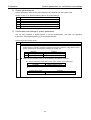
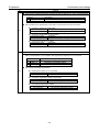
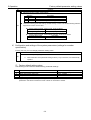
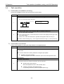
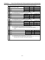
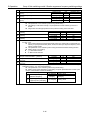
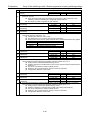
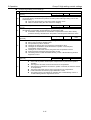
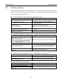
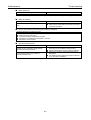
Safety precautions
■
Please fully observe
Warning
Unpack after checking upside and downside.
Injuries may occur.
Verify no discrepancies between the product you received and the product you ordered. Installing
incorrect product can result in injuries and damages.
Injuries and failures may occur.
Make sure to read the instruction manual and observe the instructions before inspection, operation,
maintenance, and inspection.
Electrical shock, injuries and fire may occur.
Do not use faulty, damaged, and burnt-out driver, motor and converter.
Injuries and fire may occur.
Please be aware that temperatures on driver, motor and peripheral equipment become high.
Fire may occur.
Do not use driver, motor and converter outside the scope of the specification.
Electrical shock, injuries and failures may occur.
Use the specified combination of motor and converter.
This can result in fire and failures.
For driver and motor, do not perform measurement of insulation resistance and dielectric strength
voltage.
Failures may occur.
Correctly and properly perform wiring.
Injuries may occur.
iii
Safety precautions
Please fully observe
Do not put heavy things on, or climb on the system.
Injuries may occur.
Make sure to observe the specified installation direction.
This can result in fire and failures.
Do not apply high impacts.
This can result in failures.
Never install the system in the area where it may be exposed to water, near corrosive/ flammable
gaseous, or by combustible material.
This can result in fire and failures.
Do not apply static electrical charge and high voltage to motor resolver cable and converter connectors.
This can result in failures.
Perform wiring in accordance with electrical installation technical standards and internal wiring standards.
Burnout or fire may occur.
Do not block and let any foreign materials into inlet/outlet.
Fire may occur.
Maintain the specified distances for layout inside of driver control cabinet.
This can result in fire and failures.
It is very dangerous to carry the system, so carefully carry the system as not to fall and roll over.
Injuries may occur.
iv
Safety precautions
Please fully observe
Install the system in incombustible material, such as metal.
Fire may occur.
No protective equipments are supplied with motor. Protect the system with overcurrent protective device,
earth leakage circuit breaker, overtemperature thermostat, and emergency stop equipment.
Injuries and fire may occur.
Do not touch heat releasing fin and regenerative resistor of driver and motor while power being
distributed or after a while power is turned off, as the temperatures on them become high.
Burn injuries may occur.
Stop operation immediately when any abnormality occurred.
Electrical shock, injuries, and fire may occur.
Never make excessive adjustment change as operation becomes unstable.
Injuries may occur.
Perform test operation by fixing motor with motor separated from mechanical systems, and then install
the motor after performing the operation check.
Injuries may occur.
When alarm activated, eliminate the cause, secure the safety, reset the alarm, and then re-start
operation.
Injuries may occur.
Confirm that input power voltage is within the specification.
This can result in failures.
v
Safety precautions
Please fully observe
Do not approach equipments after restoration from instantaneous interruption of service, as sudden
re-start can occur.
(Design the machine so as to ensure safety even sudden re-start occurs.)
Injuries may occur.
Do not externally and continuously rotate motor during servo-off with standard speciation driver with
dynamic brake, as the dynamic brake will generate heat and this will cause dangers.
Fire and burn injuries may occur.
Carefully perform maintenance and inspection as temperature on driver frame becomes high.
Burn injuries may occur.
Please contact us to repair. Disassembly can cause inoperative.
This can result in failures.
It is very dangerous to carry the system, so carefully carry the system as not to fall and roll over.
Injuries may occur.
Do not hold cables and motor rotating part to carry the system.
Failures and injuries may occur.
Dispose any driver, motor and converter properly as general industrial wastes.
vi
Safety precautions
Please fully observe
For repairing, if any, contact us. Any insulation failure in the motor and/or short-circuited or broken wires
in any cables may occur depending on the motor operating environments or conditions. If you keep on
using the system without repairing the faulty conditions, the motor becomes unable to demonstrate the
original performance, the driver becomes damaged or other trouble may occur.
This can result in failures.
Use the specified combination of motor and converter.
This can result in failures.
Remember to make a note of parameters.
This can result in failures.
Never attempt to modify any cables.
This can result in failures.
Tightly lock the connectors and make sure that the screws are securely tightened without any loosening.
This can result in failures.
Make proper service parts available (drivers, motors, converters, cables, etc. for replacement).
This can result in failures.
For cleaning, do not use any thinner but use alcohol.
This can result in failures.
The motor produces regenerative electric power when reducing a large load moment of inertia. The
regenerative electric power is normally charged in the capacitor in the driver. However, in case where
higher regenerative electric power is continuously generated, it fails to be fully stored in the capacitor and
the motor becomes shut down.
Change the operating conditions (speed, acceleration/deceleration, operating duty) otherwise
make proper regenerative resistor available externally.
vii
Safety precautions
Please fully observe
In the applications involving repeated operations through an angle of within 45 [°], be sure to perform the
angular movement at an angle exceeding 90 [°] at least once a day.
This can result in failures.
Where rotation supporting parts (bearings, ball screws, etc.) are to be additionally installed outside the
motor, be sure to complete the center alignment properly (within a runout of 0.01 [mm]). Remember that
any excessive offset loads or excessive loads can cause abnormality in the bearings in the motor.
This can result in failures.
Ensure that the bending radius of motor cable lead wire (7) and resolver cable lead wire (7) becomes larger
than R30[mm].
This can result in failures.
Never attempt to use any motor cable lead wire and resolver cable lead wire in any moving parts.
This can result in failures.
Ensure that the connections between lead wires and connectors are free from exposure to any stress (tension,
vibration, etc.) to avoid possible broken wire and/or poor contact.
This can result in failures.
Ensure that the bending radius of motor cable (8) is larger than R43 [mm] and be sure to tightly secure
the motor cable.
This can result in failures.
Install the power system (AC supply source, motor cable) and the signal system properly by separating
them from each other. Never attempt to bundle the systems nor pass them through any same duct.
This can result in failures.
In any possible case where cables may be exposed to severe vibration, secure the cables next to the
connectors to protect the connectors from exposure to stresses.
This can result in failures.
viii
Safety precautions
■
Please fully observe
Prohibition
Never expose the motor, driver and converter to any water and oil. Do not store nor operate the system in
the area where it may be exposed to rain and water drops, or toxic gasses or liquids exist.
This can result in failures.
Do not perform overhaul.
This can result in fire and electrical shock.
Do not remove nameplate.
Never cut any cables into segments for extension, shortening or splicing.
This can result in failures.
Never attempt to overhaul the motor body.
This can result in failures.
Do not remove the casings from driver and converter.
This can result in failures.
Do not impact the motor directly with a hammer or other tools.
Direct impact on the sides of motor or the parts installed on the motor can cause degraded accuracy of
internal detector.
This can result in failures.
The specifications of dynamic brake include limitations on allowable load and rotational speed.
In the operation of position alignment, limit the operating actions to 360[°] within the allowable load of
inertial moment.
This can result in failures.
ix
Safety precautions
■
Please fully observe
Mandatory
Store the system within the specified temperature and humidity “-20°C to 65°C, 90%RH or less(no
condensation)” away from direct sunlight.
Driver and converter
Temperature -20[°C] to 65[°C]
Humidity 90[%RH] or less (No condensation)
Motor
Temperature 0[°C] to 40[°C]
Humidity 20 to 80[%RH] (No condensation)
This can result in failures.
Place emergency stop circuit outside the product so that operation can be stopped and power supply can
be shut down instantaneously. Place a safeguard circuit outside driver so as to shut off main circuit power
supply when alarm activated.
Going out of control, injuries, burnout, fire, and secondary damages can occur.
Following the power-on sequence, remember to complete the estimation of magnetic pole position.
In the estimation of magnetic pole position, the rotational part of motor moves through the maximum
angle of ±18 [°].
Going out of control, injuries, burnout, fire, and secondary damages can occur.
Please operate within the specified range of temperature and humidity.
Driver and converter
Temperature: 0[C] to 55[C]
Humidity: 90%RH or less (No condensation)
Motor
Temperature: 0[C] to 40[C]
Humidity: 20 to 80[%RH] (No condensation)
This can result in burnout and failures.
Do not overload the products which may cause collapses.
Injuries may occur.
Allowable momentum load, allowable axial load, and allowable radial load vary depending on the size of
individual motors. Make sure your operating conditions are suitable the allowable loads.
This can result in failures.
x
Safety precautions
Please fully observe
Any excessive offset loads or excessive loads can cause permanently deformed rotors and/or faulty
bearings in the motor. Remember to prevent the motors from possible falling and exposure to any impact
during the installation of motors, and also to protect the motors against possible impact due to external
interference during the transportation.
This can result in failures.
Install every motor on the surface of flatness of 0.02 [mm] or less.
This can result in failures.
Use driver software with version A or later for motor M-PB3030JN001 and converter
M-ECC-PB3030GA201.
Alarm will be output and cannot operate the motor.
xi
Table of contents
1.
Preface .............................................................................................................................................................. 1
1.1
Illustration of system components ................................................................................................................... 1-1
1.2
Coding for reference number of individual parts.............................................................................................. 1-2
1)
Reference number of driver ..................................................................................................................... 1-2
2)
Reference number of motor ..................................................................................................................... 1-2
3)
Reference number of converter ............................................................................................................... 1-3
4)
Reference number of motor ..................................................................................................................... 1-3
5)
Reference number of converter cable ...................................................................................................... 1-3
1.3
Part names...................................................................................................................................................... 1-4
1)
Driver ....................................................................................................................................................... 1-4
2)
Motor........................................................................................................................................................ 1-5
3)
Converter ................................................................................................................................................. 1-5
2.
Specifications ................................................................................................................................................... 2
2.1
Motor ............................................................................................................................................................... 2-1
1)
Motor specifications ................................................................................................................................. 2-1
2)
Load on the motor .................................................................................................................................... 2-2
3)
Direction of rotation of motor .................................................................................................................... 2-2
2.2
Driver .............................................................................................................................................................. 2-3
1)
Specifications of driver ............................................................................................................................. 2-3
2)
Input command, position feedback signal output, general input, general output...................................... 2-4
2.3
Power supply .................................................................................................................................................. 2-6
1)
Main circuit power supply capacity, control power supply capacity .......................................................... 2-6
2)
Incoming current, leakage current............................................................................................................ 2-6
2.4
1)
2.5
Position feedback signal ................................................................................................................................. 2-7
Position feedback signal output ............................................................................................................... 2-7
Specifications for analog monitor .................................................................................................................... 2-8
1)
Monitor output .......................................................................................................................................... 2-8
2)
Monitor for velocity, torque, and position deviation .................................................................................. 2-9
2.6
1)
Specifications for dynamic brake................................................................................................................... 2-10
Allowable frequency, instantaneous tolerance, decreasing the rotation angle of the dynamic brake ..... 2-10
2.7
Regenerative control ..................................................................................................................................... 2-11
2.8
Converter ...................................................................................................................................................... 2-12
1)
Specifications of converter ..................................................................................................................... 2-12
3.
Installation ........................................................................................................................................................ 3
3.1
Driver .............................................................................................................................................................. 3-1
1)
Precautions .............................................................................................................................................. 3-1
2)
Unpacking ................................................................................................................................................ 3-2
xii
Table of contents
3)
Mounting direction and location ............................................................................................................... 3-3
4)
Control arrangement within the machine ................................................................................................. 3-3
3.2
Motor ............................................................................................................................................................... 3-4
1)
Precautions .............................................................................................................................................. 3-4
2)
Unpacking ................................................................................................................................................ 3-4
3)
Installation ................................................................................................................................................ 3-4
4)
Motor mounting method ........................................................................................................................... 3-5
3.3
Converter ........................................................................................................................................................ 3-7
1)
Precautions .............................................................................................................................................. 3-7
2)
Unpacking ................................................................................................................................................ 3-8
3)
Installation ................................................................................................................................................ 3-8
3.4
1)
Cable (motor and converter) ........................................................................................................................... 3-9
Precautions .............................................................................................................................................. 3-9
4.
Wiring ................................................................................................................................................................ 4
4.1
Wiring for main circuit power supply, control power, regenerative resistance, and protective grounding ........ 4-1
1)
Part name and function ............................................................................................................................ 4-1
2)
Wire ......................................................................................................................................................... 4-1
3)
Wire diameter-allowable current .............................................................................................................. 4-2
4)
Recommended wire diameter .................................................................................................................. 4-2
5)
Crimping of wires ..................................................................................................................................... 4-3
6)
High voltage circuit terminal; tightening torque ........................................................................................ 4-3
4.2
Wiring with Host Unit ....................................................................................................................................... 4-4
1)
CN1 signal and pin number (wiring with host unit) ................................................................................... 4-4
2)
CN1 connector disposition ....................................................................................................................... 4-5
3)
Signal name and its function .................................................................................................................... 4-5
4)
Terminal connection circuit....................................................................................................................... 4-6
5)
Example of wiring with CN1 ................................................................................................................... 4-12
4.3
1)
Peripheral equipments .................................................................................................................................. 4-13
Power supply capacity and peripherals list ............................................................................................ 4-13
5.
Operation .......................................................................................................................................................... 5
5.1
System parameters ......................................................................................................................................... 5-1
1)
Confirmation of specifications .................................................................................................................. 5-1
2)
System parameters list ............................................................................................................................ 5-3
3)
Confirmation and settings of system parameters ..................................................................................... 5-3
4)
Confirmation and settings of the system parameters (settings for encoder specification) ........................ 5-5
5)
Factory default setting values .................................................................................................................. 5-5
5.2
Test operation ................................................................................................................................................. 5-6
xiii
Table of contents
1)
Confirmation of installation and wiring ..................................................................................................... 5-6
2)
Confirmation of movement ....................................................................................................................... 5-6
3)
Confirmation of I/O signal ........................................................................................................................ 5-7
4)
Confirmation of device operation ............................................................................................................. 5-9
5.3
Driver status display ...................................................................................................................................... 5-10
1)
Default display ....................................................................................................................................... 5-10
2)
Alarm display ......................................................................................................................................... 5-10
5.4
Operation sequence ...................................................................................................................................... 5-11
1)
Operation sequence from power turn on to power shut off at the standard shipment setting ................ 5-11
2)
Stop sequence at alarm ......................................................................................................................... 5-13
3)
Sequence of alarm reset ........................................................................................................................ 5-15
4)
Sequence when power is turned OFF during operation (During servo ON) ........................................... 5-16
5.5
Monitor function ............................................................................................................................................ 5-17
1)
Monitor function ..................................................................................................................................... 5-17
2)
Description of monitor ............................................................................................................................ 5-18
5.6
Analog monitor and digital monitor ................................................................................................................ 5-22
5.7
Setting parameters ........................................................................................................................................ 5-23
1)
Parameters list ....................................................................................................................................... 5-23
5.8
Parameter functions ...................................................................................................................................... 5-30
5.9
Control block diagram ................................................................................................................................... 5-80
5.10
SEMI F47 supporting function ....................................................................................................................... 5-83
“Control system” ..................................................... 5-83
1)
Parameter setting General parameters Group8
2)
Operational sequence ............................................................................................................................ 5-83
3)
Notes ..................................................................................................................................................... 5-83
6.
Adjustments ..................................................................................................................................................... 6
6.1
Servo tuning functions and basic adjustment procedure ................................................................................. 6-1
1)
Servo tuning functions ............................................................................................................................. 6-1
2)
Tuning method selection procedure ......................................................................................................... 6-2
6.2
Automatic tuning ............................................................................................................................................. 6-3
1)
Use the following parameters for automatic tuning .................................................................................. 6-3
2)
Automatically adjusted parameters in auto-tuning ................................................................................... 6-6
3)
Adjustable parameters during auto-tuning ............................................................................................... 6-6
4)
Unstable functions during auto-tuning...................................................................................................... 6-7
5)
Auto-tuning characteristic selection flowchart .......................................................................................... 6-8
6)
Adjustment method for auto-tuning .......................................................................................................... 6-9
7)
Monitoring servo gain adjustment parameters ....................................................................................... 6-10
8)
Manual tuning method using auto-tuning results.................................................................................... 6-10
6.3
Automatic tuning of notch filter ...................................................................................................................... 6-11
xiv
Table of contents
1)
Operation method .................................................................................................................................. 6-11
2)
Setting parameters................................................................................................................................. 6-11
6.4
Automatic tuning of FF vibration suppression frequency............................................................................... 6-12
1)
Operation method .................................................................................................................................. 6-12
2)
Setting parameters................................................................................................................................. 6-12
6.5
Using manual tuning ..................................................................................................................................... 6-13
1)
Servo system configuration and servo adjustment parameters ............................................................. 6-13
2)
Basic manual tuning method for velocity control .................................................................................... 6-15
3)
Basic manual tuning method for position control ................................................................................... 6-15
6.6
Model following control.................................................................................................................................. 6-16
1)
Automatic tuning method for model following control ............................................................................. 6-16
2)
Manual tuning method for model following control ................................................................................. 6-17
6.7
Tuning to suppress vibration ......................................................................................................................... 6-18
1)
FF vibration suppression control ............................................................................................................ 6-18
2)
Model following vibration suppression control........................................................................................ 6-18
3)
Tuning methods ..................................................................................................................................... 6-20
6.8
Using disturbance observer function ............................................................................................................. 6-21
7.
Digital Operator ................................................................................................................................................ 7
7.1
Digital Operator names and functions ............................................................................................................. 7-1
7.2
Modes ............................................................................................................................................................. 7-1
1)
Changing modes ...................................................................................................................................... 7-1
2)
Mode contents ......................................................................................................................................... 7-2
7.3
Setting and display range................................................................................................................................ 7-3
7.4
Status display mode ........................................................................................................................................ 7-4
1)
Driver status display................................................................................................................................. 7-4
2)
Over-travel status display ........................................................................................................................ 7-4
3)
Status display of regenerative overload warning, and overload warning.................................................. 7-4
4)
Alarm code and driver status code when alarm occurs............................................................................ 7-4
5)
Alarm reset when alarm activated ............................................................................................................ 7-5
6)
How to check the software version of driver ............................................................................................ 7-5
7)
How to check Information 1, Information 2 (driver information), and Information 3 (Motor Code) ............ 7-6
8)
How to set pass ward ............................................................................................................................... 7-7
9)
How to cancel password .......................................................................................................................... 7-7
7.5
Editing parameters .......................................................................................................................................... 7-8
1)
Basic parameters, editing system parameters ......................................................................................... 7-8
2)
Editing general parameters ...................................................................................................................... 7-9
7.6
How to tune automatic notch frequency ........................................................................................................ 7-11
7.7
How to tune automatic FF vibration suppression frequency.......................................................................... 7-12
xv
Table of contents
7.8
Velocity-controlled JOG Operation ................................................................................................................ 7-13
7.9
Automatic tuning result writing ...................................................................................................................... 7-14
7.10
Automatic setting of motor parameter ........................................................................................................... 7-15
7.11
Alarm history display ..................................................................................................................................... 7-15
7.12
How to clear alarm history............................................................................................................................. 7-16
7.13
Monitor display .............................................................................................................................................. 7-16
7.14
Fixed monitor display .................................................................................................................................... 7-17
7.15
Motor code-setting of motor used ................................................................................................................. 7-17
8.
Maintenance ..................................................................................................................................................... 8
8.1
Trouble shooting ............................................................................................................................................. 8-1
8.2
List of warning and alarm ................................................................................................................................ 8-3
1)
Warning List ............................................................................................................................................. 8-3
2)
Alarm List ................................................................................................................................................. 8-4
8.3
Trouble shooting when alarm activated ........................................................................................................... 8-7
1)
Alarm display ........................................................................................................................................... 8-7
2)
Corrective action for alarm ....................................................................................................................... 8-7
8.4
Inspection...................................................................................................................................................... 8-26
9.
Appendix........................................................................................................................................................... 9
9.1
Standards conformity ...................................................................................................................................... 9-1
1)
Standards conformity ............................................................................................................................... 9-1
2)
Over-voltage category, protection grade, pollution level .......................................................................... 9-2
3)
Connection and installation ...................................................................................................................... 9-2
4)
UL file number.......................................................................................................................................... 9-2
9.2
Compliance with EN Directives ....................................................................................................................... 9-3
1)
Conformity verification test....................................................................................................................... 9-3
2)
Requirements for driver installation to achieve the EMC certification ...................................................... 9-4
3)
Requirements for converter installation to achieve the EMC certification ................................................ 9-5
9.3
Outline drawing ............................................................................................................................................... 9-6
1)
Motor........................................................................................................................................................ 9-6
2)
Driver ....................................................................................................................................................... 9-8
3)
Converter ................................................................................................................................................. 9-9
4)
Motor cable .............................................................................................................................................. 9-9
5)
Converter Cable ..................................................................................................................................... 9-10
9.4
Optional parts ................................................................................................................................................ 9-11
1)
Connectors ............................................................................................................................................ 9-11
2)
Mounting bracket ................................................................................................................................... 9-11
3)
Setup software and serial communication ............................................................................................. 9-12
xvi
Table of contents
9.5
Regenerative resistor .................................................................................................................................... 9-13
9.6
Supplementary items for usage .................................................................................................................... 9-14
1)
Homing .................................................................................................................................................. 9-14
2)
Setting procedures for parameters of magnetic pole position estimation ............................................... 9-15
xvii
1
1.
Preface
1.1
Illustration of system components ........................................................................................................................ 1-1
1.2
Coding for reference number of individual parts................................................................................................... 1-2
1)
Reference number of driver .............................................................................................................................. 1-2
2)
Reference number of motor.............................................................................................................................. 1-2
3)
Reference number of converter ........................................................................................................................ 1-3
4)
Reference number of motor.............................................................................................................................. 1-3
5)
Reference number of converter cable .............................................................................................................. 1-3
1.3
Part names........................................................................................................................................................... 1-4
1)
Driver ................................................................................................................................................................ 1-4
2)
Motor ................................................................................................................................................................ 1-5
3)
Converter.......................................................................................................................................................... 1-5
1
1.Preface
1.1
Illustration of system components
TSR
Wiring breaker (MCCB)
Used to protect power line.
Turns off the power supply when
overload runs.
Enables parameter setup and
monitoring through communication
with a PC.
Noise filter
Installed to protect power line
from external noise.
RS-232C
[Electromagnetic contactor]
Switches power On/Off.
Please place safeguard circuit.
MEGATORQUE
MOTOR SETUP
[External regenerative resistor]
[Host equipment]
When the capacity is found insufficient for
high-frequency operation or other
applications, use an external regenerative
resistor.
Converter cable
Motor cable
Converter
Motor
1-1
1. Preface
1.2
Composition of reference number of individual parts
Coding for reference number of individual parts
1) Reference number of driver
M-EGA - 15 A 2 3 01
Driver design serial number
01: Standard
Command input method
3: Pulse train input
Resolver
2: Incremental
Input supply voltage
A: 200[VAC]
Maximum output current capacity
15: 15[Arms]
30: 30[Arms]
Driver Model EGA
✔
At the time of shipment from the factory, the driver has been set in the “standard setting values.”
Depending on the specifications of your system, the “system parameters” and “general parameters”
must be changed.
Remember to select proper settings for your system, referring to the following sections.
◆ “System parameters”
◆ “Factory default standard settings”
◆ “Setting of parameters”
2) Reference number of motor
M-PB 1 006 JN 001
Motor design serial number
001: Standard
Resolver
JN: Incremental
Maximum output torque
006: 6 [N•m]
015: 15 [N•m]
030: 30 [N•m]
060: 60 [N•m]
Motor size code
1: Equivalent to motor O.D. of 102 [mm]
3: Equivalent to motor O.D. of 152 [mm]
MEGATORQUE MOTOR PB series
1-2
1. Preface
Composition of reference number of individual parts
3) Reference number of converter
M-ECC - PB1006 GA 2 01
Converter design serial number
01: Standard
Resolver
2: Incremental
Driver code
GA: Driver Model EGA
Motor code
Converter Model ECC
4)
Reference number of motor
M-CA
004
A1 01
Design serial number
01: Standard
A1: Standard
Cable length
002: 2[m]
004: 4[m]
008: 8[m]
Motor cable
5)
Reference number of converter cable
M-CC 004
A1
01
Design serial number
01: Standard
A1: Standard
Cable length
002: 2[m]
004: 4[m]
008: 8[m]
Converter cable
1-3
1.Preface
1.3
1)
Part names
Part names
Driver
Inside the front cover (OPEN)
Digital Operator operation keys
Analog monitor connector
CN5: Parts number on plug
Connector: DF11-4DS-2C
Contact: DF11-2428SCA
(Hirose Electric Co., Ltd.)
5-digit 7-segment LED
Control power status LED
(POWER-Blue)
Main circuit power LED
(Red-CHARGE)
PC communication connector
CN2: Parts number on plug
MUF-PK8K-X
(J.S.T Mfg. Co., Ltd.)
Main circuit power input
Control power input
Regenerative
resistor connector
CNA: Parts number on plug
MSTBT2.5/ 8-STF-5.08LUB
(Phoenix Contact)
Connector for control signal
CN1: Parts number on plug
Plug: 10150-3000PE
Shellkit: 10350-52A0-008
(Sumitomo 3M Ltd.)
Motor connector
CNB: Parts number on plug
MSTBT2.5/3-STF-5.08
(Phoenix Contact)
Protective ground
terminal
Converter connector
EN1: Parts number on plug
Plug: 36210-0100PL
Shellkit: 36310-3200-008
(Sumitomo 3M Ltd.)
1-4
1.Preface
2)
Part names
Motor
Hollow hole
Dust cover (Non-rotational part)
Rotor (Rotational part)
Stator (Non-rotational part)
Motor connector
Resolver connector
3)
Converter
Converter connector
Resolver connector
1-5
2
2.
Specifications
2.1
Motor .................................................................................................................................................................... 2-1
1)
Motor specifications .......................................................................................................................................... 2-1
2)
Load on the motor ............................................................................................................................................ 2-2
3)
Direction of rotation of motor ............................................................................................................................ 2-2
2.2
Driver ................................................................................................................................................................... 2-3
1)
Specifications of driver...................................................................................................................................... 2-3
2)
Input command, position feedback signal output, general input, general output .............................................. 2-4
2.3
Power supply ....................................................................................................................................................... 2-6
1)
Main circuit power supply capacity, control power supply capacity................................................................... 2-6
2)
Incoming current, leakage current .................................................................................................................... 2-6
2.4
1)
2.5
Position feedback signal ...................................................................................................................................... 2-7
Position feedback signal output ........................................................................................................................ 2-7
Specifications for analog monitor ......................................................................................................................... 2-8
1)
Monitor output .................................................................................................................................................. 2-8
2)
Monitor for velocity, torque, and position deviation ........................................................................................... 2-9
2.6
1)
Specifications for dynamic brake........................................................................................................................ 2-10
Allowable frequency, instantaneous tolerance, decreasing the rotation angle of the dynamic brake.............. 2-10
2.7
Regenerative control .......................................................................................................................................... 2-11
2.8
Converter ........................................................................................................................................................... 2-12
1)
Specifications of converter.............................................................................................................................. 2-12
2
2.Specifications
2.1
Motor
Motor
1)
Motor specifications
Designation
Item [Unit]
Motor outside
diameter
Max. output
torque
Rated output
torque
Motor height
Motor hollow
hole
Max. speed
Rated speed
Resolution of
position sensor
Absolute
positioning
accuracy
Positioning
repeatability
Allowable axial
*4
load
Allowable
*5
radial load
Allowable
moment load
Rotor moment
of inertia
Allowalble load
moment of
inertia
Mass
M-PB1006JN001
M-PB3015JN001
M-PB3030JN001
M-PB3060JN001
[mm]
102
152
[N•m]
6
15
30
60
[N•m]
2
5
10
20
92
126
[mm]
75
35
[mm]
56
-1
[s ]
-1
[s ]
10
5
[counts/rev]
8
1
524 288
*1
[arc-sec]
112
[arc-sec]
±5
*2
[N]
1000 / 120
[N]
[N•m]
*3
*2
2000 / 200
270
540
9
20
*3
2
0.0026
0.014
0.016
0.021
2
0 to 0.26
0 to 1.1
0 to 1.4
0 to 3.1
[kg•m ]
[kg•m ]
[kg]
Environmental conditions
2.6
5.8
7.2
10.2
Ambient temperature: 0-40 [°C], Humidity: 20-80%RH, Indoor use only.
Free from dust, condensation and corrosive gas. IP30 equivalent.
*1: Accuracy at an ambient temperature of 25±5 [°C]
*2: Load in the direction toward the lead wire from the loading side on the motor shaft
*3: Load in the direction toward the loading side from the lead wire on the motor shaft
*4: When the radial load is 0 [N].
*5: When the axial load is 0 [N].
2-1
2.Specifications
2)
Motor
Load on the motor
L
F
F
F
A
(2) Assuming the F refers to an external force:
(1) Assuming the F refers to an external force:
L
(3) Assuming the F refers to an external force:
 Axial load: Fa = F + weights of fixture, workpiece, etc.
 Radial load: Fr = F + weights of fixture, workpiece, etc.
 Moment load: M = 0
 Moment load: M = F × L
 Moment load: M = F × (L+A)
Distance between the bearing and the rotor end face
Motor model No.
PB1006
PB3015
PB3030
PB3060
✔
✔
✔
3)
Dimension A [mm]
22.2
22.9
Limit the axial load Fa to the allowable axial load.
Limit the radial load Fr to the allowable radial load.
Limit the moment load M to the allowable moment load.
Direction of rotation of motor
CW … Position signal output (PS data): Increase
CCW … Position signal output (PS data): Decrease
✔
✔
Direction of rotation of motor is defined as counterclockwise (CCW) or clockwise (CW)
when viewed from the loading side.
PS data can be confirmed by “Monitor ID16, 17 ABSPS.”
2-2
2.Specifications
2.2
Driver
Driver
1)
Specifications of driver
■General specifications
Designation
Item
Control function
Control system
Three phase
Main Circuit
Power
Single phase
Control
power
Single phase
M-EGA-15A2301
Position control
IGBT:PWM control Sinusoidal drive
200 to 230[VAC]+10,−15[%],50/60[Hz]±3[Hz]
200 to 230[VAC]+10,−15[%],
220 to 230[VAC]±10[%],
50/60[Hz]±3[Hz]
50/60[Hz]±3[Hz]
200 to 230[VAC]+10,−15[%],50/60[Hz]±3[Hz]
Ambient
0 to 55[℃]
temperature
Storage
−20 to +65[℃]
temperature
Environment Operation/Storage Below 90[%RH] (no condensation)
humidity
Elevation
1000[m] or below
2
Vibration
4.9[m/s ]
2
Shock
19.6[m/s ]
External dimensions
160×40×130 [mm]
(H×W×D)
Weight
0.75 [kg]
✔
M-EGA-30A2301
160×50×130 [mm]
0.9 [kg]
Power source voltage should be within the specified range
■Built-in functions
Protection functions
Digital operator
Dynamic brake circuit
Regeneration process circuit
Monitor
Over current, Current detection error, Overload, Regeneration error, Driver
overheating, External overheating, Over voltage, Main circuit power low
voltage, Main circuit power supply open phase, Control power supply low
voltage, Encoder error, Over speed, Speed control error, Speed feedback
error, Excessive position, Position command pulse error, Built-in memory
error, Parameter error
Status display, Monitor display, Alarm display, Parameter setting,
Test operation, Adjustment mode
Built-in
Built-in
-1
Speed monitor (VMON)
2.0[V]±10[%] (at 1000[min ])
Torque (TCMON)
2.0[V]±10[%] (at 100[%])
2-3
2.Specifications
2)
Driver
Input command, position feedback signal output, general input, general output
Input command
◆
Position command
Maximum input pulse
frequency
Position
command Input pulse form
5[Mpps] (CW+CCW pulse, Code + Pulse)
1.25[Mpps] (90-phase difference two-phase pulse)
CW+CCW command pulse,
Code + Pulse train command or
90[]-phase difference two-phase pulse train command
N/D (N=1 to 2097152, D=1 to 2097152)
Electronic gear

however, 1/2097152 ≦ N/D ≦ 2097152
Position command timing
CW move pulse train + CCW pulse train
F-PC
t1
t3
t2
ts1
T
R-PC
Stage up time (t1): ≦0.1[μs]
Duty[(t3/T)x100]: 50[%]
Stage down time (t2): ≦0.1[μs]
Change of pulse time: ts1>2[μs]
Pulse trains with 90[°]phase difference
t6 t7
t4
F-PC
t5
T
t3
R-PC
t1
t2
CCW
CW
Stage up time (t1): ≦0.1[μs]
Duty [(t3/T) x100]: 50[%] 
Stage down time (t2): ≦0.1[μs]
Minimum phase difference between pulse edges (t4,t5,t6,t7): >250[ns]
Code + Pulse train
F-PC
T
ts1
ts2
t1
R-PC
t1
ts3
t3
t2
Stage up time (t1): ≦0.1[μs]
Duty [(t3/T) x100]: 50[%]
Stage down time (t2): ≦0.1[μs]
Change of pulse time: ts1, ts2, ts3>2[μs]
2-4
2.Specifications
Driver
Position feedback signal output
Position feedback
signal
N/32768(N=1 to 32767), 1/N(N=1 to 64) or 2/N(N=3 to 64)
General input
Sequence input
Interactive photo coupler (sink, source connection): ×6 input
Line receiver: ×2 input
Input power voltage range: 5[VDC]±5[%] / 12 to 24[VDC]±10[%],
100[mA] or over (24[VDC])
Servo ON, Alarm reset, Torque limit, CW rotation prohibit, Command prohibit,
CCW rotation prohibit, Command prohibit, Forced discharge, Emergency stop,
Gain switching, Internal speed setting, Start of estimation of magnetic pole
position, etc.
Refer to [Group9 Condition settings for enabling function] for all the functions
and input time function-enabled.
General output [NPN output]
Sequence output
Open collector output: ×8 output
External power supply voltage (OUT-PWR): 5[VDC]±5[%] / 12[VDC] to
24[VDC]±10[%], 20[mA] or over
Circuit power for output signal: 5[VDC]±5[%] / Maximum current value 10[mA]
(per 1 output)
Circuit power for output signal: 12 to 15[VDC]±10[%] / Maximum current value
30[mA](per 1 output)
Circuit power for output signal: 24 [VDC]±10[%] / Maximum current value 50
[mA] (per 1 output)
Servo ready, Power ON, Servo ON, Torque limiting, Low speed, Velocity
attainment, Matching speed, Zero speed, Command acceptable, Status of gain
switch, Velocity loop proportional control status, CW- OT, CCW-OT, Warning,
Alarm code (3[bit]), Start of estimation of magnetic pole position, etc.
Refer to [GroupA Settings for Generic Output Outputting Condition/Monitor
Output selection/ Serial Communications]
2-5
2.Specifications
2.3
Power supply and caloric value
Power supply
1)
Main circuit power supply capacity, control power supply capacity
✔
2)
Driver Input
voltage
Motor model
200[VAC]
PB1006
PB3015
PB3030
PB3060
Rated
output
[W]
63
157
314
125
Rated main circuit
power supply [kVA]
Control
power supply
[VA]
0.3
0.5
1.0
2.0
40
Values are of rated speed, torque ratings.
Incoming current, leakage current
Incoming current
Driver Input
voltage
200[VAC]
✔
✔
✔
Control circuit (Max. value in 1[ms]
after power-on sequence)
40[A](O-P)
Main circuit (Max. value in 1.2[s]
after power-on sequence)
22[A](O-P)
Using thermistor for incoming prevention circuit of control power supply. This is the
maximum current value under normal temperature conditions when 230[VAC] is supplied.
Incoming current value is the value when 230[VAC] is supplied.
When the power is turned ON again immediately after disconnection, power supply
disconnection is repeated for a short period of time, ambient temperature is high, or, the
thermistor temperature rises, the incoming current exceeding the above table may pass.
Leakage current
Leakage current
0.8[mA]
✔
These values are applicable when a tough rubber sheath cable of 2[m] is used as a power
line. In the case of a shorter or longer cable length, values of the above table should be
selected as closely as possible.
✔
The machine should be grounded so that dangerous voltage does not occur at the main part
of the machine, such as the operation panel, etc., during a period of emergency leakage
current.
✔
The value of leaked current is the measured value using ordinary leak checkers (Filter
700[Hz]).
When electric leakage current of high frequency flows through the floating capacity of the
motor winding, power cable or driver, malfunctions may occur in the short circuit breaker
and protective relay in the power supply electric circuit. Use the inverter as an electricity
leakage breaker to provide countermeasures for incorrect operations.
2-6
2.Specifications
2.4
Output of position feedback signal
Position feedback signal
1)
Position feedback signal output
Driver outputs “90[]-phase difference two-phase pulse (phase A, phase B) and resolver pulse
(phase Z).” Pulse output can change the division ratio by parameter.
Set the general parameter “Group C ID04 Encoder Output Pulse Division.”
― ―
Output signal “A phase pulse output (A0/A0)” outputs from “CN1-3 pin, 4 pin.”
― ―
Output signal “B phase pulse output (B0/BO)” outputs from “CN1-5 pin, 6 pin.”
― ―
Output signal “Z phase output (Z0/ZO)” outputs from “CN1-7 pin, 8 pin.”
Output signal under CW rotation
Power control
ON
Phase B is advanced 90[] more than Phase A
Phase A pulse
Phase B pulse
Phase Z pulse
t
Max2[s]
✔
✔
✔
The signal is indefinite for 2[s] after booting
“Positions feedback signal output” delays about 224[μs].
Phase Z output is 80 times in motor 1-rotation based on rise up or rise down edge of Phase
A or Phase B with the width of one pulse of Phase A. (does not determine the position
relation of Phase Z or Phases A&B.
When other than 1/1 is set as division ratio, Phase A and Phase B are divided but Phase Z is
output with original pulse width.
2-7
2.Specifications
2.5
Analog monitor
Specifications for analog monitor
1)
Monitor output
Pin numbers and signal names for monitor output
1
3
2
4
CN5
Connector model number on board: DF11-4DP-2DSA (01)
Housing model number on receiving equipment: DF11-4DS-2C
Connector model number on receiving equipment: DF11-2428SCA
General input/output connector CN1
CN5
Analog monitor output 1 (MON1)
CN1-30
CN5-3
Analog monitor output 2 (MON2)
Disabled
CN5-4
Digital monitor output (DMON)
Disabled
CN5-2
GND
CN1-31
CN5-1
2-8
2.Specifications
2)
Analog monitor
Monitor for velocity, torque, and position deviation
■Electrical specifications
Output voltage range: ±8[VDC]
Output resistance: 1[kΩ]
Load: less than 2[mA]
Monitor output is indefinite at the time of power ON/OFF and may output 12[VDC] + around 10[%].
■Velocity command, velocity monitor
Velocity command, Velocity monitor output
Output
voltage
Output
voltage
2V
2V
2V
CCW
CW
-1
-1000min-1
0
0
CCW
Output
voltage
1000min
-1000min-1
1000min-1
CW
CCW
-1000min-1
CW
0
1000min-1
-2V
-2V
■Torque command, torque monitor
Torque command, torque monitor output
Output
voltage
Output
voltage
Output
voltage
2V
2V
CCW
CW
-TR
0
TR
(Rated torque)
-2V
CCW
0
TR
CW
CCW
-TR
-TR
2V
0
TR
CW
-2V
■Position deviation monitor
Position deviation monitor output
Output
voltage
20mV
Output
voltage
20mV
CW
-1
CCW
Output
voltage
0
1pulse
20mV
CCW
0
-1
-20mV
2-9
1puls
e
CW
20mV
CW
CCW
-1
0
1pulse
2.Specifications
2.6
Dynamic brake
Specifications for dynamic brake
1)
Allowable frequency, instantaneous tolerance, decreasing the rotation angle of the dynamic
brake
■Allowable frequency of the dynamic brake (main circuit power ON/OFF)
Limit the positioning operation to a range within 360 [°] within the allowable load moment of inertia.
■Operation intervals
In basic terms, operation of the dynamic brake in six (6) minute intervals is acceptable. If the brake is to
be operated more frequently, the motor speed must be reduced sufficiently.
Refer to the following expression to find a standard of operation:
6[min]
2
(Rated rotation speed/maximum rotation speed in use)
■If/When load inertia moment (JL) substantially exceeds allowable load inertia moment or if/when
rotation through an angle exceeding 360 [°] is made, abnormal heat can generate due to
dynamic brake resistance. Take precautions against (Overheat alarm of the dynamic break) or
(failure of dynamic brake resistance). Please consult us if such a situation is evident.
■Instantaneous tolerance of dynamic brake
ERD [J]
360
The consumption of energy ERD by dynamic brake resistance in one dynamic brake operation is as
follows:
ERD=
1
×
(JM+JL) ×
(2πN)
2
2
2
JM: Moment of inertia of motor rotor [kg・m ]
2
JL: Load inertia moment [kg・m ]
-1
N: Rotational speed [s ]
2-10
2.Specifications
2.7
■
Regenerative control
Calculation of the rotational energy which MEGATORQUE MOTOR has in the process
of deceleration
Calculate the rotational energy based on the following expression.
2
Rotational energy = 1/2×J×ω [J]
2
= 1/2×J×(2πN) [J]
J = J r+J m
Jr:: Moment of inertial of rotor [kg•m2]
Jm: Moment of inertia of load [kg•m2]
N: Rotational speed [s-1]
■
Available energy from storage in the internal capacitor
The regenerative energy internal capacitor can handle by charging is different depending upon the designation of
driver.
Designation of driver
M-EGA-15A2301
M-EGA-30A2301
■
Energy absorbed in the capacitor[J]
17
24
Calculation of the energy which can be consumed in the external regenerative resistor
Energy consumed in the external regenerative resistor[J] = Rotational energy[J] – Energy absorbed in the capacitor[J]
When the result of the above calculation is found 0 or less, there is no need for additional installation of external
regenerative resistor.
When the calculation result is found exceeding 0, determine the required capacity for the regenerative resistor based
on the calculations described below.
■
Calculation of the required capacity for the external regenerative resistor
Capacity required for external regenerative resistor [W]
= Energy consumed in the external regenerative resistor [J]/(Operating cycle [s]×0.25)
0.25: Duty factor of regenerative resistor
When calculation result is found 80 or less: Use the external regenerative resistor (Optional model: M-FAE0004).
When calculation result is found 220 or less: Use the external regenerative resistor (Optional model: M-FAE0005).
When calculation result is found exceeding 220, consult us.
2-11
2.Specifications
2.8
Converter
Converter
1)
Specifications of converter
General specifications
Rated input voltage
Rated input current
Operating
environment
4.75 to 5.4[VDC]
150[mA] (max)
Ambient
temperature
Storage
temperature
Operation and
storage humidity
Vibration
0 to 55[°C]
-20 to +65[°C]
90[%RH] or less (no condensation)
2
4.9[m/s ]
Outside dimensions
73×61×23.5[mm]
(H×W×D)
Weight
0.135[kg]
✔
Remember to limit the supply voltage to the specifications.
Performance
Resolution
Communication
524,288 [count/revolution]
Protocol
EIA RS-485
Type
Start-stop synchronization (NRZ)
Baud rate
2.5 [Mbps]
2-12
3
3.
Installation
3.1
Driver ································································································································································· 3-1
1)
Precautions························································································································································ 3-1
2)
Unpacking·························································································································································· 3-2
3)
Mounting direction and location ························································································································· 3-3
4)
Control arrangement within the machine ··········································································································· 3-3
3.2
Motor ································································································································································· 3-4
1)
Precautions························································································································································ 3-4
2)
Unpacking·························································································································································· 3-4
3)
Installation ························································································································································· 3-4
4)
Motor mounting method ····································································································································· 3-5
3.3
Converter ··························································································································································· 3-7
1)
Precautions························································································································································ 3-7
2)
Unpacking·························································································································································· 3-8
3)
Installation ························································································································································· 3-8
3.4
1)
Cable (motor and converter) ······························································································································ 3-9
Precautions························································································································································ 3-9
3
3.Installation
3.1
Driver
Driver
1) Precautions
When installing, please be sure to protect the following precautions.
■
Various precautions
The device should be installed on non-flammable surfaces only. Installation on or near flammable
materials can cause fire.
Do not stand, and put heavy items on the driver.
Operate the device within the specified environmental conditions.
Do not drop the device or subject it to excessive shock.
Make sure no screws or other conductive or flammable materials get inside the driver.
Do not obstruct the air intake and exhaust vents.
The attachment direction should be observed strictly.
Please contact our office if the driver is to be stored for a period of 3 years or longer. The capacity of the
electrolytic capacitors decreases during long-term storage.
Any damaged parts and parts with the mounting parts have been damaged shall be fixed by returning to
our company immediately.
■
If enclosed in a cabinet
The temperature inside the cabinet can exceed the external temperature depending on the power
consumption of the device and the size of the cabinet. Consider the cabinet size, cooling, and placement,
and make sure the temperature around the driver does not exceed 55[°C]. For longevity and reliability
purposes it is recommended to keep the temperature below 40[°C].
■
If there is a vibration source nearby
Protect the driver from vibration by installing it on a base with a shock absorber.
■
If there is a heat generator nearby
If the ambient temperature may increase due to convection or radiation, make sure the temperature near
the driver does not exceed 55[°C].
■
If corrosive gas is present
Long-term use may cause contact failure on the connectors and connecting parts.
Never use the device where it may be exposed to corrosive gas.
■
If explosive or combustible gas is present
Never use the device where explosive or combustible gas is present. The device’s relays and contacts,
regenerative resistors and other parts can arc (spark) and can cause fire or explosion.
■
If dust or oil mist is present
The device cannot be used where dust or oil mist is present. If dust or oil mist accumulates on the device,
it can cause insulation deterioration or leakage between the conductive parts, and damage the driver.
■
If a large noise source is present
If inductive noise enters the input signals or the power circuit, it can cause a malfunction. If there is a
possibility of noise, inspect the line wiring and take appropriate noise prevention measures. A noise
filter should be installed to protect the driver.
3-1
3.Installation
Driver
2) Unpacking
Verify the followings when the product arrives. If you find any discrepancy, contact your distributor
or sales office.
■
Verify that the driver reference number is the same as ordered.
The reference number is located on the main label, following the word “MODEL”.
■
Verify that there is no problem in the appearance of driver.
Driver
Example of driver label
A
Label
Serial Number
Month (two digits) + Year (two digits) + Day (two digits) + Serial number (four digits) + version
✔
When driver M-EGA-15A2301, motor M-PB3030JN001, and converter M-ECC-PB3030GA201 are used
together, use driver with version A or later. When the combination is not appropriate, alarm will be
output.
Driver version is also displayed inside the cover of upper front.
Inside the cover of
upper front
Version
A
✔
3-2
3.Installation
Driver
3) Mounting direction and location
In the case of rear-mounting
In the case of front-mounting
Front mounting
M4
M4
M4
M4
✔
Ventilation
Refer to optional parts, Appendix, for metal fittings for front mounting.
4) Control arrangement within the machine
■ Leave at least 50 [mm] space above and below the driver to ensure unobstructed airflow from the inside
of the driver and the radiator. If heat gets trapped around the driver, use a cooling fan to create airflow.
■ Make sure the temperature around the driver does not exceed 55[°C]. For longevity and reliability
purposes it is recommended to keep the temperature below 40[°C].
■ Leave at least 10 [mm] space on both sides of the driver to ensure unobstructed airflow from the heat
sinks on the side and from the inside of the driver.
■ If the driver is installed on its side, make sure that the ambient temperature does not exceed 50[°C], and
mount the back panel to a metal plate.
✔ Recommended metal plate thickness is 2[mm] or more
■ Since M-EGA-30A2301 is equipped with ventilation fan on its side, installation of driver as shown below is
recommended.
Front view
Side view
50mm or more
50mm or more
Fan
I
I
I
Driver
10mm or 10mm or
more
more
10mm or
more
50mm or more
3-3
Venti
50mm or more
3.Installation
3.2
Converter
Motor
1) Precautions
■
Various precautions
The device should be installed on non-flammable surfaces only. Installation on or near flammable
materials can cause fire.
Do not stand, and put any very heavy loads.
Operate the device within the specified environmental conditions.
Do not drop the device or subject it to excessive shock.
The attachment direction should be observed strictly.
Any damaged parts and parts with the mounting parts have been damaged shall be fixed by returning to
our company immediately.
Please contact us for long-term period storage (for 3 years or more).
2) Unpacking
Verify the followings when the product arrives. If you find any discrepancy, contact your distributor
or sales office.
■
Verify that the reference number of the motor is the same as ordered.
The reference number is located on the nameplate, following the word “MODEL”.
■
Verify that there is no problem in the appearance of motor.
Motor
Nameplate
3) Installation
Please note the following regarding the installation location and mounting method for the motor.
The motor is designed for indoor use. Make sure to Install it indoors.
Ambient temperature: 0 to 40[°C]
Storage temperature: 0 to 40[°C]
Ambient humidity: 20 to 80[%]
Good ventilation, no corrosive or explosive gases present.
No dust or dirt accumulation in the environment.
Easy access for inspection and cleaning.
3-4
3.Installation
Converter
4) Motor mounting method
■ Location and environment for installation of motor
✔
✔
✔
✔
✔
✔
✔
Use the motor indoors free from any dust and corrosive gas.
Operate the motor in the environment at an ambient temperature of 0 to 40 [°C].
The motor is not dust-proof and waterproof design (IP30 equivalent). Use the motor in the environment
free from any water or oil.
If the mounting base is not rigid enough for installation of motor, mechanical resonance may occur.
Remember to install and fix the motor securely onto the mounting base having high stiffness.
Make sure that the motor mounting surface has a flatness of 0.02 [mm] or less.
The motor may be installed in either orientation horizontal or vertical.
For tightening torque and penetration depth of screws, follow the table below.
Motor model
PB1006
PB3015
PB3030
PB3060
Screw
M4
Tightening torque [N•m]
3.4 or less
Penetration depth [mm]
4 to 5.5
M6
13 or less
7 to 8.5
Table fixing bolt Table
Flatness of mounting surface:
0.02 mm or less.
MEGATORQUE
MOTOR
Mounting base
Motor fixing bolt
Since the installation condition shown below can cause mechanical resonant vibration or failure of
estimation of magnetic pole due to low rigidity of the mounting base and the load, installation of
motor to mounting base and load to motor have to be secure and rigid.
Load
The load is not directly
applied to the motor rotor.
MEGATORQUE
MOTOR
The motor is not directly
installed on the mounting
base.
✔
✔
Mounting base
Allow the load to be directly applied to the motor rotor.
Install the motor directly onto the mounting base.
3-5
3.Installation
Motor
■ Coupling the load to the motor
✔
✔
For installation of load, use the bolt hole in the rotor. Install the load securely with great care not to allow
any looseness.
For tightening torque and penetration depth of screws, follow the table below.
Motor model
PB1006
PB3015
PB3030
PB3060
Screw
M4
Tightening torque [N•m]
3.4 or less
Penetration depth [mm]
5 to 6.5
M6
13 or less
7 to 8.5
■ Checking the operating conditions
The MEGATORQUE MOTOR system involves significantly larger moment of inertia for load
compared to the moment of inertial for rotor. Allowable load moment-of-inertia by motor size is
shown in the table below.
✔
2
Motor model
Rotor inertia moment [kg•m ]
PB1006
PB3015
PB3030
PB3060
0.0026
0.014
0.016
0.021
Allowable load moment-of-inertia
2
[kg•m ]
0 to 0.26
0 to 1.1
0 to 1.4
0 to 3.1
Remember to check for appropriate allowable moment load, allowable axial load and allowable radial
load for your specific applications of the motor.
3-6
3.Installation
3.3
Converter
Converter
1) Precautions
Follow the precautions listed below when installing the converter.
■ General precautions
Remember that installation to or near any combustibles can cause a fire.
Never attempt to place any heavy materials on the converter or do not stand on the converter.
Use the converter within the range of specified environmental conditions.
Do not fall the converter nor expose it to any strong impact.
Protect the converter against possible entry of screws, metal fragments or other conductive substances
and combustibles.
If the converter or any internal part is found damaged, immediately return it to us for proper repair.
■ Precautions for installation
In order to ensure extended service life and high reliance, use the converter at a temperature below
40[°C].
■ Where any heating element is located nearby
Even if temperature increase is expected due to thermal convection and/or radiation, keep the
surroundings of converter below 55[°C].
■ Where corrosive gas is present
Extended use can cause contact failure in the connectors and contact elements. Never use the converter
in any location exposed to corrosive gas.
■ Where explosive or combustible gas is present
Never use the converter in any location exposed to explosive or combustible gas.
■ Where any source of generating large noise is present
Malfunction may occur due to contaminated input signal/power supply circuit with induction noise.
Where there is a possibility of noise contamination, make proper provisions such as consideration of
power line wiring and prevention of noise generation.
3-7
3.Installation
Converter
2) Unpacking
On receipt of the product, make checks listed below. Should any abnormality be discovered,
immediately contact us.
■ Check the reference number of the converter for proper match with your ordered product. Locate the
reference number next to “MODEL” on the label on the product.
■ Check the external appearance of the converter for any defect.
Converter
Label
3) Installation
Mounting hole (4 locations)
Typical installation
M4
M4
3-8
3.Installation
3.4
Cable
Cable (motor and converter)
1) Precautions
Follow the precautions listed below when installing the cable.
■ General precautions
Remember that installation near any combustibles can cause a fire.
Never attempt to place any heavy materials on the converter or do not stand on the cable.
Use the cable within the range of specified environmental conditions.
Do not fall the cable nor expose it to any strong impact.
If the cable is found damaged, immediately return it to us for proper repair.
Do not cut cables for extension, reduction, or connection.
Do not give stress such as tension or vibration to connecting part of cable and connector.
■ Precautions for installation
In order to ensure extended service life and high reliance, use the cable at a temperature below 40[°C].
If cable is to be exposed to severe vibration, fix the cable near connector so that connector does not suffer
from stress.
■ Where any heating element is located nearby
Even if temperature increase is expected due to thermal convection and/or radiation, keep the
surroundings of cable below 40[°C].
■ Where corrosive gas is present
Extended use can cause contact failure in the connectors and contact elements. Never use the cable in
any location exposed to corrosive gas.
■ Where explosive or combustible gas is present
Never use the cable in any location exposed to explosive or combustible gas.
■ Where any source of generating large noise is present
Where there is a possibility of noise contamination, make proper provisions such as consideration of
power line wiring and prevention of noise generation.
3-9
4
4.
Wiring
4.1
Wiring for main circuit power supply, control power, regenerative resistance, and protective grounding ············· 4-1
1)
Part name and function ···································································································································· 4-1
2)
Wire ·································································································································································· 4-1
3)
Wire diameter-allowable current ······················································································································· 4-2
4)
Recommended wire diameter··························································································································· 4-2
5)
Crimping of wires ·············································································································································· 4-3
6)
High voltage circuit terminal; tightening torque ································································································· 4-3
4.2
Wiring with Host Unit ············································································································································ 4-4
1)
CN1 signal and pin number (wiring with host unit) ··························································································· 4-4
2)
CN1 connector disposition································································································································ 4-5
3)
Signal name and its function ···························································································································· 4-5
4)
Terminal connection circuit ······························································································································· 4-6
5)
Example of wiring with CN1···························································································································· 4-12
4.3
1)
Peripheral equipments ······································································································································· 4-13
Power supply capacity and peripherals list ····································································································· 4-13
4
4.Wiring
4.1
Allowable current, recommended wire diameter
Wiring for main circuit power supply, control power,
regenerative resistance, and protective grounding
1) Part name and function
Connector
marking
Terminal name
Remarks
Single phase
Main circuit power supply
R・T
or
R・S・T
Control power supply
r・t
Motor connector
Converter connector
CNB
EN1
Safeguard connector
Regeneration resistance
connector
RB1・RB2
Maker maintenance
✔
✔
200 to 230[VAC] +10[%], -15[%]
50/60[Hz]±3[%]
220 to 230[VAC]±10[%],
50/60[Hz]±3[Hz]
Three-phase 200 to 230[VAC] +10[%], -15[%]
50/60[Hz]±3[Hz]
Single phase 200 to 230[VAC] +10[%], -15[%]
50/60[Hz]±3[Hz]
Connected with motor cable connector
Connected with converter cable connector
Connected with grounding wire of power supply and of
motor.
Connects any external regenerative resistor to RB1 / RB2
terminals.
For maker maintenance. Do not connect anything.
For connection to CNB and EN1, be sure to use the dedicated cables. The cables cannot be cut off nor
spliced due to the specifically designed lines.
If main circuit power supply is used as single phase power source, specification of supply voltage is
different depending upon motor and driver used.
2) Wire
Electric wires for use in driver main circuit power are shown below.
■ Wire type
Kinds of wires
Conductor allowable
temperature [°C]
Code
Name
PVC
Common vinyl electric wire
---
IV
600V electric wire
60
HIV
Special heat-resistant vinyl wire
75
✔
✔
✔
The information in this table is based on rated armature current running through three bundled lead
wires at ambient temperature of 40[°C]. Use the electric wire beyond proof-pressure 600[V].
When wires are bundled or put into a wire-duct, such as a hardening vinyl pipe or a metallic conduit,
take the allowable current reduction ratio into account.
At high ambient temperature,, service life of the wires becomes shorter due to heat-related
deterioration. In this case, we recommend using heat-resistant vinyl wires.
4-1
4.Wiring
Wiring example
3) Wire diameter-allowable current
AWG sides
20
19
18
16
14
✔
✔
✔
Nominal cross-sectional area
[mm2]
0.5
0.75
0.9
1.25
2.0
Conductor resistance
[Ω/km]
39.5
26.0
24.4
15.6
9.53
Allowable current over ambient temperature [A]
30[°C]
40[°C]
55[°C]
6.6
5.6
4.2
8.8
7.0
5.4
9.0
7.7
5.8
12.0
11.0
8.3
23.0
20.0
15.0
This is reference value in the case of a special heat-resistant vinyl wire (HIV).
The diameter of an electric wire and allowable current in the case of doing the bundle line of the three
electric wires are shown.
Use it below by the above-mentioned allowable current.
4) Recommended wire diameter
The recommendation electric wire diameter used for driver is shown below.
■ Input voltage 200[VAC]
Main circuit power
supply
(R・S・T)
2
mm
AWG No
1.25
✔
✔
✔
16
Control
power
supply
mm2
1.25
Regeneration
resistance
AWG No
16
1.25
16
mm2
AWG No
2.0
14
The information in this table is based on rated armature current flowing through three bundled lead wires at
ambient temperature of 40[°C].
When wires are bundled or put into a wire-duct, take the allowable current reduction ratio into account.
At high ambient temperature, service life of the wires becomes shorter due to heat-related deterioration. In
this case, use special heat-resistant vinyl wire (HIV).
4-2
4.Wiring
Crimping processing, tightening torque
5) Crimping of wires
Insert the wire into ferrule, and use a special tool to crimp it in.
Insert the ferrule deep into the connector, and tighten it with a special minus screwdriver or
something. The recommended torque is 0.5 to 0.6 [N・m].
Process 1
Process 3
Wire
Process 2
Ferrule
■
Model number of recommended ferrules and crimping tools for various wire sizes
2
✔
✔
✔
✔
mm
AWG
Model number
0.75
19
AI0.75-8GY
1.0
18
AI1-8RD
1.5
16
AI1.5-8BK
2.5
14
AI2.5-8BU
GY: Gray, RD: Red, BK: Black, BU: Blue
2
2
Crimping tool model number: 0.25 to 6[mm ] : CRIMPFOX UD 6-4, 0.75 to 10[mm ]: CRIMPFOX UD
10-4GY
Manufactured by Phoenix Contact.
The procedures above are recommendations. Consider the use of equivalent products for both ferrule
and crimping tool.
6) High voltage circuit terminal; tightening torque
Terminal marking
CNA
1.18 [N・m]
M4 (screw size)
0.5 to 0.6 [N・m]
4-3
4.Wiring
4.2
Wiring with host unit
Wiring with Host Unit
1) CN1 signal and pin number (wiring with host unit)
■
CN1 terminal sequence
F-PC
F-PC
AO
Driver
26
3
AO
27
+5V SG
4
SG
BO
47
5
28
6
29
7
48
8
R-PC
R-PC
BO
ZO
ZO
SG
PS
NC
9
21
NC
10
20
T-COMP
11
22
SG
PS
ZOP
SG
12
23
NC
OUT-PWR
18
NC
49
OUT1
17
NC
39
19
OUT2
40
CONT-COM
OUT3
50
41
37
42
36
43
35
44
34
45
33
46
CONT1
OUT4
OUT5
CONT2
OUT6
CONT3
OUT7
CONT4
CONT5
OUT8
OUT-COM
CONT6
24
OUT-COM
32
25
CONT7
13
CONT7
14
MON1
CONT8
CONT8
15
30
16
31
SG
38
NC
1
NC
2
4-4
SG
4.Wiring
Wiring with host unit
2) CN1 connector disposition
■
CN1 10150-3000PE
(Soldered side)
24 22 20 18 16 14 12 10 8
6
4
2
23 21 19 17 15 13 11 9
7
5
3
1
49 47 45 43 41 39 37 35 33 31 29 27
50 48 46 44 42 40 38 36 34 32 30 28 26
25
3) Signal name and its function
Terminal
number
Signal
name
Description
Terminal
number
Signal name
Description
1
2
NC
NC
NC
NC
30
31
MON1
SG
3
A0
A phase pulse output
13
CONT7
4
5
6
7
A0
BO
― ―
BO
ZO
/A phase pulse output
B phase pulse output
/B phase pulse output
Z phase pulse output
14
15
16
38
CONT7
CONT8
― ― ― ― ―
CONT8
SG
Analog monitor output
Common for pin 30
Position Command Pulse
Function ∙ shutdown at
Zero Velocity Function (+)
Position Command Pulse
Function ∙ shutdown at
Zero Velocity Function (-)
Alarm Reset Function (+)
Alarm Reset Function (-)
Common for pins 13 to 16
8
ZO
/Z phase pulse output
32
CONT6
9
10
PS
― ―
PS
Resolver signal output
/Resolver signal output
33
34
CONT5
CONT4
11
12
ZOP
SG
Z phase pulse output
Common for pins 3 to 11
35
36
CONT3
CONT2
17
NC
NC
37
CONT1
18
NC
NC
50
CONT-COM
19
NC
NC
39
OUT1
20
NC
NC
40
OUT2
21
NC
NC
41
OUT3
22
23
T-COMP
SG
Torque compensation input
Common for pin 22
42
43
OUT4
OUT5
26
27
28
F-PC
――― ―
F - PC
R-PC
Command pulse input
Command pulse input
Command pulse input
44
45
46
OUT6
OUT7
OUT8
29
47
48
R - PC
SG
SG
Command pulse input
Common for pins 26・27
Common for pins 28・29
49
24
25
OUT-PWR
OUT-COM
OUT-COM
― ―
― ― ― ― ―
― ―
――― ―
• Terminal number 13 to 16 and 32 to 27 : factory default standard settings.
• Terminal number 39 to 46 : factory default standard settings.
4-5
CW over Travel Function
CCW over Travel
Function
Deviation Clear Function
Magnetic Pole Position
Estimation Function
Emergency Stop Function
Servo-ON Function
General input power
supply
In-Position Window
Magnetic Pole Position
Estimation Ready
While Operation Setup
Completion
Magnetic Pole Position
Estimation End
Alarm Code Bit 5
Alarm Code Bit 6
Alarm Code Bit 7
While Alarm Status
Power source for general
output
General output Common
4.Wiring
Wiring with host unit
4) Terminal connection circuit
Terminal
No.
1
2
3
4
5
6
7
8
Symbol
Name
NC
NC
A0
― ―
A0
BO
― ―
BO
ZO
−
−
A phase pulse output
/A phase pulse output
B phase pulse output
/B phase pulse output
Z phase pulse output
― ―
/Z phase pulse output
ZO
Description
−
The signal of A phase of a resolver, B phase pulse, and a
starting point Z phase pulse is outputted. Connect with a
line receiver.
Twisted pair
Driver
HD26C31-or
equivalent
A
―
Host unit
HD26C32-or
equivalent
3
A
4
B
5
―
BO
6
Z
―
7
Z
8
SG
12
9
PS
10
PS
― ―
Resolver signal
output
/Resolver signal
output
Make sure to connect SG.
Absolute position data output signal of a resolver.
Driver
HD26C31-or
equivalent
Twisted pair
Host unit
HD26C32-or
equivalent
PS
9
PS
10
SG
12
Make sure to connect SG.
11
ZOP
Z phase pulse output
Resolver Z phase pulse is output at the open collector.
[NPN output]
Max. voltage: DC30V
Max. current: 10mA
Host system
Driver
Twist pair
ZOP
11
SG
12
Remember to connect SG.
4-6
SG
SG
4.Wiring
Wiring with host unit
Terminal
No.
13
14
15
16
Symbol
CONT7
― ― ― ― ―
CONT7
CONT8
― ― ― ― ―
CONT8
Name
General input
General input
General input
General input
Description
Receivable with a line receiver. General output signals
can receive either a differential signal or an open collector
signal.
Differential output signal connection
Host unit
Driver
Twisted pair
HD26C31
correspond
1.5kΩ
1.0kΩ
13
1.0kΩ
CONT7
150Ω
14
1.0kΩ
1.0kΩ
CONT7
38
SG
HD26C32 -or
equivalent
Open collector signal output connection
Driver
Host unit
Twisted pair
1.0kΩ
13
1.5kΩ
1.0kΩ
CONT7
150Ω
14
CONT7
38
1.0kΩ
1.0kΩ
SG
HD26C32 -or
equivalent
Make sure to connect SG.
4-7
4.Wiring
Wiring with host unit
Terminal
No.
18
19
20
21
22
Symbol
Name
Description
NC
NC
NC
NC
T-COMP
−
−
−
−
Torque compensation
input
−
−
−
−
Driver
Host unit
0.01μF
T-CMP
22
1.0kΩ
10.0kΩ
1.8kΩ
0.01μF
SG
23
4-8
SG
1.8kΩ
4.Wiring
Wiring with host unit
Terminal
No.
26
Symbol
F-PC
――― ―
27
F - PC
28
R-PC
29
R - PC
――― ―
Name
Command pulse
input
Command pulse
input
Command pulse
input
Command pulse
input
Description
Command pulse input is a position command input.
Velocity command input  Velocity control type.
Three types of command input pulse.
[CW pulse + CCW pulse]
Maximum
5[Mpps]
[Code + pulse train]
Maximum
5[Mpps]
[90-phase difference two phase pulse train]
Maximum 1.25[Mpps]
Differential output signal connection
Host unit
HD26C31
correspond
Driver
Twisted pair
1.5kΩ
1.0kΩ
F-PC
1.0kΩ
26
150Ω
1.0kΩ
27
F-PC
47
1.0kΩ
SG
SG
Twisted pair
1.5kΩ
1.0kΩ
R-PC
1.0kΩ
28
150Ω
1.0kΩ
29
R-PC
48
1.0kΩ
SG SG
HD26C32-or equivalent
Be sure to connect SG.
Open collector signal output connection
Host unit
Driver
Twisted pair
1.5kΩ
1.0kΩ
F-PC
26
1.0kΩ
150Ω
1.0kΩ
27
F-PC
47
1.0kΩ
SG SG
Twisted pair
1.5kΩ
1.0kΩ
28
1.0kΩ
R-PC
150Ω
1.0kΩ
29
R-PC
48
SG
1.0kΩ
SG
HD26C32-or equivalent
4-9
4.Wiring
Wiring with host unit
Terminal
No.
30
Symbol
MON1
Name
Analog monitor
output
Description
Outputs the selection of analog monitor output 1.
Load shall be less than 2[mA].
Output resistance shall be 1[kΩ].
Output voltage range shall be ±8[V].
Driver
Host unit
MON1
1.0kΩ
30
1.0kΩ
SG
32
33
34
35
36
37
CONT6
CONT5
CONT4
CONT3
CONT2
CONT1
General input
General input
General input
General input
General input
General input
0.001μF
31
General input circuit is connected with the transistor
circuit of a relay or an open collector.
Power supply & voltage range:
5[VDC]±5[%] / 12[VDC] to 24[VDC]±10[%]
Minimum current: 100[mA]
[Sink circuit example]
Host unit
Driver
CONT-COM
2.2kΩ
50
CONT1
4.7kΩ
37
CONT2 36
CONT3 35
CONT4 34
CONT5 33
CONT6
Sink circuit type
4-10
32
4.Wiring
Wiring with host unit
Terminal
No.
39
40
41
42
43
44
45
46
49
OUT1
OUT2
OUT3
OUT4
OUT5
OUT6
OUT7
OUT8
OUT-PWR
24
OUT-COM
25
OUT-COM
Symbol
Name
General output
General output
General output
General output
General output
General output
General output
General output
General output
power supply
General output
common
General output
common
Description
General output circuit is connected with a photo-coupler or
a relay circuit.
[NPN output]
OUT-PWR (outer power supply) specification
Power supply & voltage range:5[VDC] ±5[%],
12 to 24[VDC] ±10[%]
Minimum current: 20[mA]
Specification of input circuit power
Power supply voltage range: 5[VDC] ±5[%]
Power supply voltage range: 12 to 15[VDC] ±10[%]
Power supply voltage range: 24[VDC] ±10[%]
Maximum current:5[VDC]・・・・・・・・・・10[mA]
Maximum current:12 to 15[VDC]・・・・30[mA]
Maximum current:24[VDC]・・・・・・・・・50[mA]
Driver
Host unit
OUT-PWR
Photocoupler
49
OUT1
39
OUT2
40
OUT3
41
OUT4
42
OUT5
43
OUT6
44
45
OUT7
Relay
OUT8
46
Diode
OUT-COM
24
25
OUT-COM
✔
Make sure to install diode as a surge absorber when connecting induction load, such as relay, to
general (-purpose) output.
Please carefully install diode so as not to connect polarity of diode. Failure to do this causes driver
malfunction.
4-11
4.Wiring
Wiring with host unit
5) Example of wiring with CN1
Host equipment
Driver model EGA
Polarity of the power supply may be
reversed to minus common.
CN1
50 CONT-COM
5/12/24 [VDC]
VDC
Servo-ON function
Emergency stop function
Magnetic pole position estimation input
Deviation clear function
CCW over travel function
CW over travel function
Position command pulse disabled function
SG
Alarm reset function
SG
CW command pulse input
SG
CCW command pulse input
SG
5/12/24 [VDC]
VDC
37
36
35
34
33
32
CONT1
CONT2
CONT3
CONT4
CONT5
CONT6
13
38
15
38
CONT7
SG
CONT8
SG
26
27
47
28
29
48
F-PC
/F-PC
SG
R-PC
/R-PC
SG
49
39
40
41
42
46
OUT-PWR
INP
CSETRDY
S-RDY
CSETCMP
ALM
24,25 OUT-COM
In-Position window
Magnetic pole position estimation ready
Operation setup completion
Magnetic pole position estimation end
Alarm status
3
4
5
6
7
8
12
A phase pulse output
B phase pulse output
Z phase pulse output
SG
FG
4-12
AO
/AO
BO
/BO
ZO
/ZO
SG
4.Wiring
4.3
Peripheral equipments
1) Power supply capacity and peripherals list
Input voltage
Motor model
No.
Main circuit
power supply
rating [kVA]
PB1006
0.3
PB3015
0.5
PB3030
1.0
PB3060
2.0
200[VAC]
✔
Molded case
circuit breaker
(MCCB)
Noise filter
Magnetic
contact
Surge
absorber
Model NF30 10A
MITSUBISHI
ELECTRIC
HF3030C-UQA
SOSHIN
ELECTRIC
Co., Ltd.
S-N10
MITSUBISH
I ELECTRIC
LT-C32G801WS
SOSHIN
ELECTRIC
Co., Ltd.
Please install surge absorber at the input part of driver when overvoltage such as lightning surge is applied to
driver.
4-13
5
5. Operation
5.1
System parameters ·············································································································································· 5-1
1)
Confirmation of specifications···························································································································· 5-1
2)
System parameters list ······································································································································ 5-3
3)
Confirmation and settings of system parameters ······························································································ 5-3
4)
Confirmation and settings of the system parameters (settings for encoder specification) ·································· 5-5
5)
Factory default setting values ···························································································································· 5-5
5.2
Test operation ······················································································································································ 5-6
1)
Confirmation of installation and wiring ··············································································································· 5-6
2)
Confirmation of movement ································································································································ 5-6
3)
Confirmation of I/O signal ·································································································································· 5-7
4)
Confirmation of device operation ······················································································································· 5-9
5.3
Driver status display ··········································································································································· 5-10
1)
Default display ················································································································································· 5-10
2)
Alarm display ··················································································································································· 5-10
5.4
Operation sequence ··········································································································································· 5-11
1)
Operation sequence from power turn on to power shut off at the standard shipment setting ·························· 5-11
2)
Stop sequence at alarm ··································································································································· 5-13
3)
Sequence of alarm reset ································································································································· 5-15
4)
Sequence when power is turned OFF during operation (During servo ON) ···················································· 5-16
5.5
Monitor function ················································································································································· 5-17
1)
Monitor function ··············································································································································· 5-17
2)
Description of monitor ····································································································································· 5-18
5.6
Analog monitor and digital monitor ····················································································································· 5-22
5.7
Setting parameters ············································································································································· 5-23
1)
Parameters list ················································································································································ 5-23
5.8
Parameter functions ··········································································································································· 5-30
5.9
Control block diagram ········································································································································ 5-80
5.10
SEMI F47 supporting function ···························································································································· 5-83
1)
Parameter setting General parameters Group8 “Control system” ································································· 5-83
2)
Operational sequence ····································································································································· 5-83
3)
Notes ······························································································································································· 5-83
5
5.Operation
5.1
Changing servo motor combination
System parameters
1) Confirmation of specifications
Confirm the specifications the driver, using either of the MEGATORQUE MOTOR SETUP(set up
software) or Digital Operator.
Procedure
Item and contents
Confirmation of driver specifications
■ Confirm that the specifications of the product purchased are the same as that of the
machine being used. Also, confirm the following three (3) items with statements or codes.
◆
◆
◆
1
Motor structure
Main circuit power supply voltage
Driver capacity code
■ Confirm the statement contents and codes with the MEGATORQUE MOTOR system
support tools:
Setup software or Digital Operator.
◆
Confirm with setup software.
Turn on control power (r, t) to start up setup software.
Opening System parameters tab of Parameters setting (P) shows “System
information” in the upper right of the display. Confirm in accordance with procedure
2 and later.
◆
Confirm with Digital Operator
Codes are shown at Information 1 (driver) and Information 2 (driver). Refer to
[Status Display Mode (7-4)] for Digital Operator operation.
Motor structure
Code
02
Motor structure
DDM
■ Confirm that DDM is displayed at Motor Structure in setup software.
2
■ Confirm that the Motor Structure code is shown at Information 1 (driver) of Digital Operator.
Motor Structure code
5-1
5.Operation
Confirmation of system parameters specifications
Procedure
Item and contents
Main circuit power supply voltage
Code
00
3
Main circuit power supply voltage display
200[V]
■ Using setup software, confirm that voltage value of main circuit power connected to
connector CNA or terminal block RST is displayed.
■ Using Digital Operator, confirm that codes of voltage value of main circuit power
connected to connector CNA or terminal block RST is displayed on “information 1 (driver
information).”
Main circuit power supply voltage
code
Output current capacity
Code
0C
0A
4
Output current
capacity
15[A]
30[A]
■ Confirm setup software displays the driver capacity of the driver model that you use.
■ Confirm Digital Operator displays the code of the output current capacity you use at
Information 2 (driver).
Output current capacity code
5-2
5.Operation
System parameters list, confirmation and settings
2) System parameters list
System parameters list is shown below. Settings vary depending on the system used.
Please confirm 3), 4) and the following IDs for the proper settings.
ID
00
01
02
05
0A
Contents
Control Cycle
Main Circuit Power Input Type
Regenerative Resistor Selection
Serial Encoder Resolution
Position Control Selection
3) Confirmation and settings of system parameters
Use the setup software or digital operator, to set the specifications
the driver. For operating
instructions, see [Digital Operator (7)] for the Digital Operator.
System Parameters Setting (driver)
ID
Contents
Control Cycle
■ Select the control cycle for Velocity control/ Torque control.
“High Frequency Sampling” enables increasing the frequency response of the velocity control
system. Please set at “00: Standard_Sampling” for normal use.
Selection
Standard_Sampling
High-freq_Sampling
00
01
00
Contents
Standard Sampling
High Frequency Sampling
■ “High frequency sampling mode” is not available for the following conditions:
◆
System Parameters ID0A setting value of the “Position Control Selection”
Present setting value
Contents
01:Model1
Model Following Control
or
Present setting value
02:Model2
Contents
Model Following Vibration Suppressor Control
5-3
5.Operation
ID
Confirmation and settings
Contents
Main circuit power input type
■ Set input type of main circuit power connected to CNA on driver or R, S, and T on terminal block.
Selection
00 AC_3-phase
01 AC_Single-phase
Description
3 phase AC power is supplied to the main circuit
Single phase AC power is supplied to the main circuit
■ Set according to the specifications of the main circuit power that is used as Follows:
◆
Connect to 3 phase AC power 200V
Present setting value
Description
00: AC_3-phase
3 phase AC power is supplied to the main circuit
01
◆
Connect to single phase AC power 200V.
Present setting value
Description
01: AC_Single-phase
Single phase AC power is supplied to the main circuit
◆
Connect AC 100V to R, T of CNA
Present setting value
Description
01: AC_Single-phase
Single phase AC power is supplied to the main circuit
Regenerative resistor selection
■ Set installation specification of regenerative resistor connected to CNA on driver or RB1 and
RB2 on terminal block, or the condition that regenerative resistance is not connected.
00
01
02
Selection
Not_connect
Built-in_R
External_R
Description
Regenerative resistor is not connected
Use built-in regenerative resistor
Use external regenerative resistor
■ Set to meet the flowing specifications:
02
◆
Regenerative resistor is not connected
Present setting value
Description
00: Not_connect
Regenerative resistor is not connected
◆
Use built-in regenerative resistor of the driver
Present setting value
Description
01: Built-in_R
Use built-in regenerative resistor
◆
Use external regenerative resistor
Present setting value
Description
02: External_R
Use external regenerative resistor
5-4
5.Operation
ID
Factory default parameter setting values
Contents
Position control selection
■ Select the function Position Control Mode.
00
01
02
0A
Selection
Standard
Model1
Model2
Description
Standard
Model Following Control
Model Following Vibration Suppress Control
■ Under the following parameter settings, ‘Model Flowing Control” and “Model Following Vibration
Suppressor Control” are not valid.
◆
System parameter ID00 “Control Cycle” is set as follows:
Present setting value
Description
01: High-freq_Sampling
High Frequency Sampling
◆
System parameter ID09 “Control Mode Selection” is not set as follows:
Present setting value
Description
02:Position
Position Control Mode
4)Confirmation and settings of the system parameters (settings for encoder
specification)
Factory use only. Do not change parameter setting value.
Serial encoder resolution
■ Set the divisions per single (1) shaft rotation
05
✔
When automatic motor parameter setting function (7-15) is executed, it is automatically
updated.
5) Factory default setting values
The following chart shows the default factory parameter settings.
ID
00
01
02
05
✔
Name
Setting value
Control Cycle
00:Standard_Sampling
Main Circuit Power Input Type
00:AC_3-Phase
Regenerative Resistor Selection
00:Not Connect
Serial Encoder Resolution
08:524288_FMT
By performing parameter backup function, you can save “System Parameters”, “General
parameters” and “Motor Parameters” inside of driver for restoration if needed.
5-5
5.Operation
5.2
Test operation (installation, wiring, and JOG Operation)
Test operation
1) Confirmation of installation and wiring
Confirm the installation and the wiring of the driver and the motor.
Procedure
Item and contents
Installation
■ Install the driver and the motor by referring to [Installation (3)].
Do not connect any load to the motor.
Do not connect
1
Load
MEGATORQUE
Megatorque
MOTOR
motor
Wiring, connecting  Turning on the power supply
■ Wire the power supply, motor and upper device by referring to [Wiring (4)].
Do not connect CN1 to the driver.
2
■ Turn on the power supply. Confirm that there is no alarm code displayed at the upper center
of the driver display.
If there is one, follow the instructions in [Trouble shooting When Alarm Occurs (8-7).
■ Follow “Trouble shooting (8-1)” , if the 7 segment LED does not light “≡” when powered up.
2) Confirmation of movement
Perform JOG Operation by using the setup software or the digital operator.
Procedure
1
Item and contents
Estimation of magnetic pole position
■
Perform the estimation of magnetic pole position at no load without connecting any load to
the motor.
■
The motor should start, allowing estimation of magnetic pole position.
◆
Operating using setup software:
Select the Magnetic Pole Position Estimation option from the Test Operation menu.
JOG Operation
■ Perform JOG-operation.
■ Confirm that the motor rotates CW direction and CCW direction
2
◆
Operating using setup software:
Select JOG Operation from the Test Operation menu.
◆
Confirming and setting with Digital Operator:
For operating instructions, please see [Digital Operator (7)].
5-6
5.Operation
Test operation (confirmation of I/O signal)
3) Confirmation of I/O signal
Settings for general I/O signals (CN1) are the defaults set at the time of shipment
Procedure
Item and contents
Confirmation of I/O signal
■ Allocate functions you use to CONT1 to CONT8 by selecting parameters from general
parameters Group 9.
Default setting value at shipment
1
Input
signal
CONT1
CONT2
CONT3
CONT4
CONT5
CONT6
CN1 pin
number
37
36
35
34
33
32
CONT7
13,14
CONT8
15,16
Signal selected form general parameter Group9
Setting value
Servo-ON Function
Emergency Stop Function
Estimation of Magnetic Pole Position
Deviation Clear Function
CCW over Travel Function
CW over Travel Function
Position Command Pulse Disabled Function /
Shutdown at Zero Velocity Function
Alarm Reset Function
02:_CONT1_ON
04:_CONT2_OFF
06:_CONT3_ON
08:_CONT4_ON
0B:_CONT5_OFF
0D:_CONT6_OFF
0E:_CONT7_ON
10:_CONT8_ON
Confirmation of output signals
■ Select the output signal from general parameters GroupA and allocate OUT1 to OUT 8.
Default setting value
at shipment
2
Output
signal
OUT1
OUT2
OUT3
OUT4
CN1 Pin
number
39
40
41
42
Setting value
18:_INP_ON
68:_CSETRDY_ON
02:_S-RDY_ON
4E:_CSETCMP_ON
Default setting
value at shipment
Output
signal
OUT5
OUT6
OUT7
OUT8
CN1 Pin
number
43
44
45
46
Setting value
33:_ALM5_OFF
35:_ALM6_OFF
37:_ALM7_OFF
39:_ALM_OFF
Confirmation of I/O signal
■ Confirm that the I/O signal functions fine at the monitor.
Refer to [Monitor Function (5-23)] for explanation.
3
4
◆
Confirming with setup software
Confirm from the menu monitor.
◆
Confirming with Digital Operator
For operating instructions, please see [Digital Operator (7)].
Input the Magnetic Pole Position Estimation signal
■ Please make sure that the estimation of magnetic pole position is set ready and then input
the Magnetic Pole Position Estimation signal. The motor should be energized and it
provides reciprocating action to perform the estimation of magnetic pole position.
Input servo ON signal
■ Input servo ON signal. Confirm that the motor is excited and the Digital Operator display on
the driver front is drawing the character “8”.
Display shown below indicates over travel status.
Over-travel on CW rotation.
5
Over-travel on CCW rotation.
■ Setting and changing the over-travel function can be done at the general parameters
Group9 ID00, ID01.
■ Setting and changing the emergency stop function can be done at the general parameter
Group9 ID42.
5-7
5.Operation
Procedure
Test operation (confirmation of I/O signal)
Item and contents
Command input
■ Input the command suitable for the control mode in use
■ Confirm that the motor rotates in the right direction.
6
■ If the command is input from the host unit but the motor does not rotate, confirm that the
command is input at the monitor function of setup software. "Monitor_ID13:Position
Command Pulse (FMON1)" displays input command pulse frequency.
■ If the driver does not receive the command from the host unit, the value displayed on the
monitor becomes zero.
Any of these cases could be the result of poor wiring: Confirm the wiring again.
■ Input command after receiving command reception enabling signal from driver.
Refer to “Operation sequence” for the details.
7
Power shut off
Turn off the servo-on signal. Then turn off the power supply.
5-8
5.Operation
Test operation (confirmation of I/O signal)
4) Confirmation of device operation
Connect the load to the motor and check the motor for proper operation.
Procedure
Item and contents
Connect the load.
■ Connect the load to the motor.
Connect the motor shaft
with the machine
1
2
Load
MEGATORQUE
MOTOR
Setting of load
■ Set "Gr.0_ID00: Tuning mode (TUNMODE)" to "01: AutoTun_JRAT-Fix".
■ Set inertia moment of the load device against the motor rotor inertia moment to "Gr.1_ID14:
Load Inertia Moment Ratio 1 (JRAT1)".
◆ JRAT1 set value = (Load Inertia Moment) / (Rotor Inertia Moment) × 100 [%]
Estimation of magnetic pole position.
■ Close CONT3 (CN1-35 pin) to execute estimating magnetic pole position.
■ When rigidity of the device, such as mounting base, load, and installation, is low, estimation
of magnetic pole position may not be properly implemented. Improve the rigidity of the
device before implementation.
3
■ Do not allow unbalanced load or large friction to complete estimation of magnetic pole
position properly.
4
3
■ In the estimation of magnetic pole position the rotational part of motor moves through the
maximum angle of ±18 [°]. Ensure emergency stop and over travel limit for the motor operate
properly.
Input Servo On signal
■ Input Servo-ON signal. Confirm if motor is excited and seven segments of driver front panel
displays "8".
Operation
■ Input the command (low speed); check the rotation direction, rotational speed, emergency
stop and over-travel (F-OT・R-OT) to make sure they are operating properly.
■ Be sure to stop in the event of any abnormal operation.
■ Input the command for the actual operation and start the machine.
■ If there is nothing wrong with operation and the characteristic, manual tuning is not
necessary. Refer to [Adjustments (6)] for the Servo Tuning.
5-9
5.Operation
5.3
Driver status display
1) Default display
Marking
Marking
Description
Control power supply established.
Control power supply (r, t) is established and driver ready (RDY) is
on.
Main circuit power supply established.
Main power supply (R, S, T) is established, but operation
preparation completion signal is off.
Magnetic Pole Position Estimation Ready (blinking)
Main power supply (R, S, T) is established and Magnetic Pole
Position Estimation Ready is on.
Magnetic Pole Position Estimation
Rotates after displaying the character "O" (upper half).
Status code
0
2
9
9
Operation setup completion signal established. (continuous)
Magnetic pole position estimation is completed, and Operation
setup completion signal is on.
4
Servo is on. Rotates after displaying the character “8.”
8
Description
Over-travel status at CW rotation.
Over-travel status at CCW rotation.
Marking
Description
Regenerative overload warning status.
If operation is kept on, alarm may go off.
Overload Warning status.
If operation is kept on, alarm may go off.
2) Alarm display
When an alarm occurs, the display shows the alarm code and the status code of the driver.
Marking
Description
When an alarm occurs, take corrective actions as instructed in [Maintenance (8)].
Status code of the driver
Alarm
code
Code
Status
0
Power ON status
(P-OFF)
2
Power OFF status
(P-ON)
4
Servo ready status
(S-RDY)
8
Servo ON status
(S-ON)
9
Magnetic Pole Position Estimation status
(CSETRDY)
A
Emergency stop status
(EMR)
F
Initial status
5-10
5.Operation
5.4
Operation sequence (power on)
Operation sequence
1) Operation sequence from power turn on to power shut off at the standard shipment
setting
Power ON  Servo ON
Control source
Control source
ON
2sec (Max)
(Output) Power ON permission
signal
0msec (Min)
Main circuit
power
Main power source ON
Inrush current prevention time
(Output) Power ON signal
Approx. 40msec
Dynamic brake OFF
(Output) Dynamic brake signal
100msec
50msec
(Output)
Magnetic Pole Position Estimation Ready signal
(Input)
Magnetic Pole Position Estimation Input signal
(Output)
Magnetic Pole Position Estimation End signal
(Output) Holding brake excitation
100msec
Input ON
30msec
130msec (Max)
Holding brake disengage
signal
Motor excitation
(Output) Motor excitation signal
S-RDY
S-RDY2
(Output) Operation setup completion signal
DB relay waiting time = 100msec
(Input)
Servo ON signal
Servo ON
Motor speed
Command acceptance
(Output) permission signal
✔
✔
Command
acceptance
permission
BOFFDLY(300msec) + 28msec
The frequency of the power ON/OFF of the driver shall be 5 times/hour or less and 30 times/day or less.
Please set 15 minutes or more to power ON/OFF interval.
Inrush current suppression times of driver are as follows.
Inrush Current
900 [ms]
Suppression Time
5-11
5.Operation
Operation sequence (power off)
Servo OFF  Power OFF
Control source
Control source OFF
(Min) 0msec
Main circuit power
Main power supply OFF
(Output) Power ON signal
Power ON output OFF
(Output) Operation setup completion signal
(Input) Servo ON signal
S-RDY S-RDY2
Servo OFF
Dynamic brake ON
(Output) Dynamic brake signal
Motor velocity
(Output) Holding brake excitation signal
(Output) Command acceptance permission signal
Motor stop
Holding brake engage
Command acceptance prohibition
(Output) Motor excitation signal
Motor free
BONDLY = 300msec
5-12
5.Operation
Operation sequence (at alarm)
2) Stop sequence at alarm
When an alarm occurs, the motor is stopped by either dynamic brake or servo brake (zero-speed
command). The alarm content dictates which brake to be used. Refer to [Warning and Alarm List
(8-3)]
Stop by dynamic brake at alarm
(Output)
Power ON permission signal
Power ON permission OFF
Main circuit power
(Output)
(Input)
(Output)
Operation setup completion signal
Servo ON signal
Dynamic brake signal
Main power supply OFF
S-RDY S-RDY2
Servo ON
Dynamic brake ON
Motor velocity
Alarm status
(Output)
Alarm signal
(Output)
Holding brake excitation-signal
(Output)
Command acceptance permission signal
(Output)
Motor excitation signal
Holding brake engage
Command acceptance prohibition
Motor free
5-13
5.Operation
Operation sequence (at alarm)
Stop by servo brake at alarm
(Output) Power ON permission signal
Main circuit power
(Output)
(Input)
Power ON permission OFF
Main power supply OFF
Operation setup completion signal
Servo ON signal
S-RDY S-RDY2
Servo ON
Dynamic brake ON
(Output) Dynamic brake signal
Motor stop detect
Motor velocity
(Output) Alarm signal
Alarm status
Holding brake engage
(Output) Holding brake excitation signal
(Output) Command acceptance
permission signal
Command acceptance
prohibition
(Output) Motor excitation signal
Motor free
BONDLY = 300msec
5-14
5.Operation
Operation sequence (alarm reset)
3) Sequence of alarm reset
Inputting alarm reset signal from general input signal can reset alarms.
(Output)
Power ON permission signal
Power ON permission
Main power supply ON
Main circuit power
Inrush current prevention time
(Output)
Power ON signal
S-RDY
(Output)
S-RDY2
Operation setup completion signal
DB relay waiting time = 100msec
(Input)
(Output)
(Input)
Servo ON
Servo ON signal
Alarm signal
Alarm released
Alarm reset signal
Alarm reset input (over 20msec)
✔
✔
✔
Some alarms cannot be reset unless the power is reset (control power is turned OFF and ON again). Refer
to [Warning and Alarm List (8-3)].
Clear the alarm reset signal after checking if the alarm signal is cleared.
The alarm signal cannot be cleared when the alarm condition continues, therefore, set a timeout period of
20[ms] or more to clear “alarm reset signal”.
Also, it is necessary to input the time of 20[ms] or more when the alarm reset signal is input without
checking for the alarm signal output.
5-15
5.Operation
Operation sequence (power off during operation)
4) Sequence when power is turned OFF during operation (During servo ON)
Control source
Main circuit power
(Output)
Power ON signal
(Output)
Operation setup completion signal
(Input)
(Output)
Control source OFF
Main power supply OFF
Power ON output OFF
S-RDY S-RDY2
Servo ON signal
Dynamic brake ON
Dynamic brake signal
Motor velocity
Motor stop
Holding brake engage
(Output) Holding brake excitation signal
(Output)
Command acceptance permission signal
Command acceptance prohibition
(Output) Motor excitation signal
Motor free
BONDLY = 300msec
5-16
5.Operation
5.5
Monitor function
Monitor function
1) Monitor function
ID
00
01
02
03
04
05
06
07
08
09
0A
0C
0D
0E
0F
10
11
12
Symbol
STATUS
WARNING1
WARNING2
CONT8-1
OUT8-1
VMON
VCMON
TMON
TCMON
PMON
13
FMON1
CSU
14
16
17
1A
1B
1C
1D
1E
1F
20
21
22
23
24
25
26
80
APMON
CPMON
-
ABSPS
RegP
TRMS
ETRMS
JRAT MON
KP MON
TPI MON
KVP MON
TVI MON
TCFIL MON
MKP MON
MTLMON
-EST
OPE-TIM
ACCMON
RESANG
Name
Driver status monitor
Warning status 1 monitor
Warning status 2 monitor
General Purpose Input CONT8 to 1 monitor
General Purpose Output OUT8 to 1 monitor
Velocity monitor
Velocity command monitor
Torque monitor
Torque command monitor
Position deviation monitor
Digital operator: Displays upper data
Present position
monitor(encoder)
Digital operator: Displays lower data
Digital operator: Displays upper data
Command position
monitor
Digital operator: Displays lower data
Position command pulse frequency monitor
Unit
-------------1
min
-1
min
%
%
Pulse
32
×2 Pulse
Pulse
----32
×2 Pulse
Pulse
k Pulse/s
U-phase electric angle monitor
Resolver PS data
monitor
Digital operator: Displays upper data
Digital operator: Displays lower data
deg
×2
32
Pulse
Pulse
Regenerative resistor operation percentage monitor
Effective torque monitor
Effective torque monitor (Estimated value)
Load Inertia Moment Ratio monitor
Position Loop Proportional Gain monitor
Position Loop Integral Time Constant monitor
Velocity Loop Proportional Gain monitor
Velocity Loop Integral Time Constant monitor
Torque Command Filter monitor
Model Control Gain monitor
%
%
%
%
1/s
ms
Hz
ms
Hz
1/s
Load Torque monitor (Estimate value)
%
Driver operation time
Acceleration monitor
Resolver sensor electric angle.
5-17
×2 hour
2
rad/s
Pulse
5.Operation
Monitor function
2) Description of monitor
ID
Contents
Driver status monitor [STATUS]
Code
00
Status
0
Power OFF state
(P-OFF)
2
Power ON state
(P-ON)
4
Servo ready state
(S-RDY)
8
Servo ON state
(S-ON)
9
Magnetic Pole Position Estimation Ready state (CSETRDY)
A
Emergency stop state
(EMR)
10
Alarm and power OFF state
(ALARM_P-OFF)
12
Alarm and power ON state
(ALARM_P-ON)
1A
Alarm and emergency stop state
(ALARM_EMR)
22
Gate off and power-on state
(GATE OFF_P-ON)
Warning status 1 monitor [WARNING1]
■ Displays warning status. Displays warning status under“1”or “ON”
Bit
Function
3
Regenerative load
2
Overload
Bit
Function
7
Excessive deviation
6
---
1
---
0
Temperature inside driver
01
5
Velocity controlled
4
Torque controlled
Warning status 2 monitor [WARNING2]
■ Displays warning status. Valid when“1”or“ON”.
Bit
02
Function
3
CCW direction
Over-travel
Bit
7
Function
Voltage sag
2
CW direction
Over-travel
6
Low battery
voltage
1
---
0
Main circuit power being
charged
5
4
---
---
General Purpose Input CONT8 to 1 monitor [CONT8-1]
■ Displays generic input terminal status. It will be in a photo coupler exciting state by 1 or ON.
03
Bit
Function
3
CONT4
2
CONT3
1
CONT2
0
CONT1
Bit
Function
7
CONT8
6
CONT7
5
CONT6
4
CONT5
General Purpose Output OUT8 to 1 monitor [OUT8-1]
■ Displays generic output terminal status. It will be in a photo coupler exciting state by 1 or ON.
04
05
Bit
Function
3
OUT4
2
OUT3
1
OUT2
0
OUT1
Bit
Function
7
OUT8
6
OUT7
5
OUT6
4
OUT5
■ Do not set.
5-18
5.Operation
Monitor function
Refer to the following charts for the display format of ID01 to 05 as setup software and Digital Operator
have different indicators:
■
Display of the setup software
■
Bit
7
6
5
4
3
2
1
0
0 or 1
0/1
0/1
0/1
0/1
0/1
0/1
0/1
0/1
Display of the Digital operator
Bit
ON
7
6
5
4
3
2
1
0
OFF
-
LED4
LED3
LED2
LED1
Digital operator at the front of the Driver
ID
Contents
Velocity monitor [VMON]
■ Displays the rotation speed of the motor.
06
Display range
Unit
-1
-9999 to 9999
min
Velocity command monitor [VCMON]
■ Displays the velocity command value.
07
Display range
Unit
-9999 to 9999
min-1
Torque monitor [TMON]
■ Displays the output torque.
08
Display range
Unit
-499.9 to 499.9
%
Torque command monitor [TCMON]
■ Displays the torque command value.
09
0A
Display range
-499.9 to 499.9
Unit
%
Position deviation monitor [PMON]
■ Displays the position deviation value.
◆ Setup software displays values in decimal notation.
Display range
Unit
-2147483648 to 2147483647
Pulse
◆ Digital operator displays values in hexadecimal notation.
ID
Data range
Display range
Unit
0A
Bit31 to Bit0
H.FFFF to L.0000
Pulse
5-19
5.Operation
Monitor function
ID
Contents
Actual position monitor) [APMON]
■ Displays the current position of the encoder(assuming that the position at the time the control
power was turned ON is the original mode).
As this is a free run counter, if the current position exceeds the displayed range, the maximum
reverse polarity value will be displayed.
0C
0D
◆
◆
0E
0F
Setup software displays the data on ID0C.
Display range
-9223372036854775808 to 9223372036854775807
Unit
Pulse
Digital operator displays the data on ID0C, ID0D in hexadecimal notation (32-bit data).
ID
Data range
Display range
Unit
32
0C
Bit63 to Bit32
H.FFFF to L.0000
×2 Pulse
0D
Bit31 to Bit0
H.FFFF to L.0000
Pulse
Reserved
■
Command position monitor [CPMON]
■ Displays the current position of the pulse command (assuming that the position at the time the
control power was turned ON is the original mode). As this is a free run counter, if the current
position exceeds the displayed range, the maximum reverse polarity value will be displayed.
◆
10
11
◆
Setup software displays the data on ID10.
Display range
-9223372036854775808 to 9223372036854775807
Unit
Pulse
Digital operator displays the data on ID10, ID11 in hexadecimal notation (32-bit data).
ID
Data range
Display range
Unit
32
10
Bit63 to Bit32
H.FFFF to L.0000
×2 Pulse
11
Bit31 to Bit0
H.FFFF to L.0000
Pulse
5-20
5.Operation
Monitor function
ID
12
13
Contents
Reserved
■
Position command pulse frequency monitor [FMON1]
■ Displays entered command pulse frequency.
Display range
-6000 to 6000
Unit
kPulse/s
U-phase electric angle monitor [CSU]
■ Displays U-phase electric angle. Always displayed excluding encoder errors.
14
Display range
0 to 359
Unit
deg
Serial encoder PS data monitor [ABSPS]
■ Displays position data of serial encoder.
◆
16
17
Setup software displays the data on D16.
Display range
Unit
0 to 1099511627775
Pulse
(Actual display range varies depending on the encoder specifications.)
◆
Digital operator displays the data on ID16, ID17 in hexadecimal notation (32-bit data).
ID
Data range
Display range
Unit
32
16
Bit63 to Bit32
H.FFFF to L.0000
×2 Pulse
17
Bit31 to Bit0
H.FFFF to L.0000
Pulse
Regenerative resistor operation percentage monitor [RegP]
■ Displays run rate of regenerative resistance.
1A
Display range
0.00 to 99.9
Unit
%
Effective torque monitor [TRMS]
■ Displays effective torque. Depending on the operation pattern, it may take some hours to
become stable.
1B
Display range
0 to 499
Unit
%
Effective torque monitor (Estimated value) [ETRMS]
■ Displays effective torque estimated value. Estimates from short time operation. This can be
confirmed shortly if the same operation pattern is repeated.
1C
Display range
0 to 499
1D
1E
Unit
%
Load inertia moment ratio monitor [JRAT MON]
■ Indicates present load inertia moment ratio.
You can check the value when using gain switching and auto-tuning function.
Position loop proportional gain monitor [KP MON]
■ Indicates present position loop proportional gain.
You can check the value when using gain switching and auto-tuning function.
5-21
5.Operation
Analog monitor, digital monitor
ID
1F
20
21
22
23
24
Contents
Position Loop Integral Time Constant monitor [TPI MON]
■ Displays actual Position Loop Integral Time Constant value.
Value can be confirmed when changing the gain function.
Velocity Loop Proportional Gain monitor [KVP MON]
■ Displays actual Velocity Loop Proportional Gain.
Value can be confirmed when changing gain and at Auto-tuning function.
Velocity Loop Integral Time Constant monitor [TVI MON]
■ Displays actual Velocity Loop Integral Time Constant.
Value can be confirmed when changing gain and at Auto-tuning function.
Torque Command Filter monitor [TCFIL MON]
■ Displays actual Torque Command Filter.
Value can be confirmed when changing gain and at Auto-tuning function.
Model Control Gain monitor [MKP MON]
■ Displays actual Model Control Gain.
Value can be confirmed when changing gain and at Auto-tuning function.
Load Torque monitor (Estimate value) [MTLMON-EST]
■ Displays estimated value of load torque.
Display range
-499.9 to 499.9
Unit
%
Driver operation time [OPE-TIM]
■ Is counted during period control power is being turned on. The time is displayed value x 2 hours.
25
Unit
×2 hour
26
Acceleration monitor [ACCMON]
■ Indicates motor acceleration.
◆ Setup software displays values in decimal notation.
Display range
Unit
2
-2147483648 to 2147483647
rad/s
◆
ID
26
80
5.6
Digital operator displays values in hexadecimal notation.
Data range
Display range
Bit31 to Bit0
H.FFFF L.FFFF to H.0000 L.0000
Unit
2
rad/s
RESANG
■ Resolver sensor electric angle. [RESANG]
Reports Resolver sensor electric angle.
Data range
unit
0 to 65535
pulse
Analog monitor and digital monitor
All signals and internal status of the driver can be monitored. Analog monitor output 1 is also output
from “CN1-pin30”.
■ Selection of output signal
Select and change the output signal to be used from the parameters list below.
General parameters GroupA ID10
General parameters GroupA ID11
General parameters GroupA ID12
DMON: Digital Monitor Output Signal Selection
MON1: Analog Monitor Select Output 1
MON2: Analog Monitor Select Output 2
5-22
5.Operation
5.7
Parameters list
Setting parameters
1) Parameters list
Below is the parameters list. Groups in ID order are classified.” System parameters”, “General
parameters” and “Motor parameters” are retained in the driver by keeping the parameter back-up
function in effect for restoration of the parameter(s) as needed.
■
General parameters group list
Group
Group0
Group1
Group2
Group3
Group4
Group5
Group8
Group9
Classification of the parameters in this group
Auto-tuning settings
Basic control parameter settings
FF (feed forward) vibration suppressor control/ Notch filter/ Disturbance observer settings
Model following control settings
Gain switching control/ Vibration suppressor frequency switching settings
High setting control settings
Control system settings
Function enabling condition settings
General output terminal output condition/ Monitor output selection/ Serial communication
GroupA
settings
GroupB Sequence/alarm related settings
GroupC Encoder related settings
✔ Parameters vary depending on the driver to be used.
■
General parameters Group0 “Auto-tuning settings”
ID
00
01
02
Symbol
TUNMODE
ATCHA
ATRES
03
ATSAVE
10
ANFILTC
20
ASUPTC
21
ASUPFC
Name
Tuning Mode
Auto-Tuning Characteristic
Auto-Tuning Response
Auto-Tuning Automatic
Parameter Saving
Auto-Notch Filter Tuning Torque
Command
Auto-FF Vibration Suppressor
Frequency Tuning Torque Command
Auto-FF Vibration Suppressor
Frequency Tuning Friction
Compensation Value
5-23
Standard value
00:AutoTun
00:Positioning1
5
Unit
-
Setting range
00 to 02
00 to 06
1 to 30
50.0
%
10.0 to 100.0
25.0
%
10.0 to 100.0
5.0
%
0.0 to 50.0
00:Auto_Saving
00 to 01
5.Operation
Parameters list
General parameters Group1 “Basic control parameter settings”
■
ID
Symbol
00
PCSMT
01
02
PCFIL
KP1
03
TPI1
04
TRCPGN
05
06
10
11
12
FFGN
FFFIL
VCFIL
VDFIL
KVP1
13
TVI1
14
JRAT1
15
TRCVGN
16
17
20
21
AFBK
AFBFIL
TCFIL1
TCFILOR
Name
Position Command Smoothing
Constant
Position Command Filter
Position Loop Proportional Gain 1
Position Loop Integral Time
Constant 1
Higher Tracking Control Position
Compensation Gain
Feed Forward Gain
Feed Forward Filter
Velocity Command Filter
Velocity Feedback Filter
Velocity Loop Proportional Gain 1
Velocity Loop Integral Time
Constant 1
Load Inertia Moment Ratio 1
Higher Tracking Control Velocity
Compensation Gain
Acceleration Feedback Gain
Acceleration Feedback Filter
Torque Command Filter 1
Torque Command Filter Order
Standard
value
Unit
Setting range
0.0
ms
0.0 to 500.0
0.0
30
ms
1/s
0.0 to 2000.0
1 to 3000
1000.0
ms
0.3 to 1000.0
0
%
0 to 100
0
4000
4000
1500
50
%
Hz
Hz
Hz
Hz
0 to 100
1 to 4000
1 to 4000
1 to 4000
1 to 2000
20.0
ms
0.3 to 1000.0
100
%
0 to 15000
0
%
0 to 100
0.0
500
600
2
%
Hz
Hz
Order
-100.0 to 100.0
1 to 4000
1 to 4000
1 to 3
General parameters Group2 “FF (Feed forward) vibration suppressor control/ Notch filter/
Disturbance observer settings”
■
ID
Symbol
00
01
10
20
SUPFRQ1
SUPLV
VCNFIL
TCNFILA
21
TCNFPA
22
23
24
25
26
27
30
31
32
33
TCNFILB
TCNFDB
TCNFILC
TCNFDC
TCNFILD
TCNFDD
OBCHA
OBG
OBLPF
OBNFIL
Name
FF Vibration Suppressor Frequency 1
FF Vibration Suppressor Level Selection
Velocity Command Notch Filter
Torque Command Notch Filter A
TCNFILA, Low Frequency Phase Delay
Improvement
Torque Command Notch Filter B
TCNFILB, Depth Selection
Torque Command Notch Filter C
TCNFILC, Depth Selection
Torque Command Notch Filter D
TCNFILD, Depth Selection
Observer Characteristic
Observer Compensation Gain
Observer Output Low-pass Filter
Observer Output Notch Filter
Standard
value
500
00
1000
4000
Unit
Setting range
Hz
Hz
Hz
5 to 500
00 to 03
50 to 1000
100 to 4000
00
-
00 to 02
4000
00
4000
00
4000
00
00:Low
0
50
4000
Hz
Hz
Hz
%
Hz
Hz
100 to 4000
00 to 03
100 to 4000
00 to 03
100 to 4000
00 to 03
00 to 02
0 to 100
1 to 4000
100 to 4000
General parameters Group3 “ Model following control settings"
■
ID
Symbol
00
01
02
03
KM1
OSSFIL
ANRFRQ1
RESFRQ1
Name
Model Control Gain 1
Overshoot Suppressor Filter
Model Control Antiresonance Frequency 1
Model Control Resonance Frequency 1
5-24
Standard
value
30
1500
80.0
80.0
Unit
Setting range
1/s
Hz
Hz
Hz
1 to 3000
1 to 4000
10.0 to 80.0
10.0 to 80.0
5.Operation
Parameters list
General parameters Group4 “Gain switching control/ Vibration suppressor frequency switching
settings”
■
ID
Symbol
00
01
02
03
04
05
06
10
11
12
13
14
15
16
20
21
22
23
24
25
26
30
40
41
42
50
51
52
53
54
55
KM2
KP2
TPI2
KVP2
TVI2
JRAT2
TCFIL2
KM3
KP3
TPI3
KVP3
TVI3
JRAT3
TCFIL3
KM4
KP4
TPI4
KVP4
TVI4
JRAT4
TCFIL4
GCFIL
SUPFRQ2
SUPFRQ3
SUPFRQ4
ANRFRQ2
RESFRQ2
ANRFRQ3
RESFRQ3
ANRFRQ4
RESFRQ4
Name
Model Control Gain 2
Position Loop Proportional Gain 2
Position Loop Integral Time Constant 2
Velocity Loop Proportional Gain 2
Velocity Loop Integral Time Constant 2
Load Inertia Moment Ratio 2
Torque Command Filter 2
Model Control Gain 3
Position Loop Proportional Gain 3
Position Loop Integral Time Constant 3
Velocity Loop Proportional Gain 3
Velocity Loop Integral Time Constant 3
Load Inertia Moment Ratio 3
Torque Command Filter 3
Model Control Gain 4
Position Loop Proportional Gain 4
Position Loop Integral Time Constant 4
Velocity Loop Proportional Gain 4
Velocity Loop Integral Time Constant 4
Load Inertia Moment Ratio 4
Torque Command Filter 4
Gain Switching Filter
FF Vibration Suppressor Frequency 2
FF Vibration Suppressor Frequency 3
FF Vibration Suppressor Frequency 4
Model Control Anti-resonance Frequency 2
Model Control Resonance Frequency 2
Model Control Anti-resonance Frequency 3
Model Control Resonance Frequency 3
Model Control Anti-resonance Frequency 4
Model Control Resonance Frequency 4
Standard
value
30
30
1000.0
50
20.0
100
600
30
30
1000.0
50
20.0
100
600
30
30
1000.0
50
20.0
100
600
0
500
500
500
80.0
80.0
80.0
80.0
80.0
80.0
Unit
Setting range
1/s
1/s
ms
Hz
ms
%
Hz
1/s
1/s
ms
Hz
ms
%
Hz
1/s
1/s
ms
Hz
ms
%
Hz
ms
Hz
Hz
Hz
Hz
Hz
Hz
Hz
Hz
Hz
1 to 3000
1 to 3000
0.3 to 1000.0
1 to 2000
0.3 to 1000.0
0 to 15000
1 to 4000
1 to 3000
1 to 3000
0.3 to 1000.0
1 to 2000
0.3 to 1000.0
0 to 15000
1 to 4000
1 to 3000
1 to 3000
0.3 to 1000.0
1 to 2000
0.3 to 1000.0
0 to 15000
1 to 4000
0 to 100
5 to 500
5 to 500
5 to 500
10.0 to 80.0
10.0 to 80.0
10.0 to 80.0
10.0 to 80.0
10.0 to 80.0
10.0 to 80.0
General parameters Group5 “High settling control settings”
■
ID
Symbol
00
01
02
03
CVFIL
CVTH
ACCC0
DECC0
Name
Command Velocity Low-pass Filter
Command Velocity Threshold
Acceleration Compensation
Deceleration Compensation
5-25
Standard
value
1000
20
0
0
Unit
Setting range
Hz
min-1
×50 Pulse
×50 Pulse
1 to 4000
0 to 6553.5
-9999 to +9999
-9999 to +9999
5.Operation
■
Parameters list
General parameters Group8 “Control system settings”
ID
Symbol
00
CMDPOL
10
PMOD
11
12
13
14
15
16
PCPPOL
PCPFIL
B-GER1
A-GER1
B-GER2
A-GER2
17
EDGEPOS
18
PDEVMON
19
2B
2C
2D
37
38
39
3B
3C
CLRSEL
TVCACC
TVCDEC
VCLM
TCLM-F
TCLM-R
SQTCLM
TASEL
TA
3D
TLMREST
3E
BDLY_TCMP
40
NEAR
41
INP
42
43
ZV
LOWV
44
VA
45
46
47
VCMPUS
VCMP
VCMPR
Standard
value
00:PC+_
VC+_TC+
00:F-PC_
R-PC
00:Type1
00:834nsec
1
1
1
1
00:Pulse
_Interval
00:After
_Filter
00:Type1
0
0
65535
100.0
100.0
120.0
00
100.0
-
00 to 01
ms
ms
min-1
%
%
%
%
00 to 03
0 to 16000
0 to 16000
1 to 6553.5
10.0 to 500.0
10.0 to 500.0
10.0 to 500.0
00 to 01
0.0 to 500.0
10.0
%
0.0 to 500.0
0.0
%
-100.0 to 100.0
Near Range
500
Pulse
In-Position Window
100
Pulse
Speed Zero Range
Low Speed Range
Speed Attainment Setting (High Speed
Range)
Speed Matching Unit Selection
Speed Matching Range
Speed Matching Range Ratio
50
50
min-1
min-1
1 to
2147483647
1 to
2147483647
50 to 500
0 to 6553.5
1000
min-1
0 to 6553.5
min-1
%
00 to 01
0 to 6553.5
0.0 to 100.0
Name
Position, Velocity, Torque Command Input Polarity
Position Command Pulse Selection
Position Command Pulse Count Polarity
Position Command Pulse Digital Filter
Electronic Gear 1 Numerator
Electronic Gear 1 Denominator
Electronic Gear 2 Numerator
Electronic Gear 2 Denominator
Positioning Methods
In-Position Signal/ Position Deviation Monitor
Deviation Clear Selection
Velocity Command Acceleration Time Constant
Velocity Command Deceleration Time Constant
Velocity Limit Command
Forward Direction Internal Torque Limit Value
Reverse Direction Internal Torque Limit Value
Sequence Operation Torque Limit Value
Torque Attainment select
Torque attainment
The amount of torque limit value restoration when power
restored.
Torque Addition Command during Holding Brake Release
Action Delay Time
5-26
-1
00_min
50
5.0
Unit
Setting range
-
00 to 07
-
00 to 02
-
00 to 03
00 to 07
1 to 2097152
1 to 2097152
1 to 2097152
1 to 2097152
-
00 to 01
5.Operation
Parameters list
General parameters Group9 “Function enabling condition settings”
■
ID
Symbol
Name
Standard value
00
01
02
04
05
F-OT
R-OT
AL-RST
CLR
S-ON
0D:CONT6_OFF
0B:CONT5_OFF
10:CONT8_ON
08:CONT4_ON
02:CONT1_ON
11
INH/Z-STP
0E:CONT7_ON
00 to 27
12
13
14
15
16
17
18
19
1A
20
21
22
23
24
GERS
GC1
GC2
SUPFSEL1
SUPFSEL2
PLPCON
MDLFSEL1
MDLFSEL2
CSET
SP1
SP2
SP3
DIR
RUN
00:Always_Disable
00:Always_Disable
00:Always_Disable
00:Always_Disable
00:Always_Disable
01:Always_Enable
00:Always_Disable
00:Always_Disable
06:CONT3_ON
00:Always_Disable
00:Always_Disable
00:Always_Disable
00:Always_Disable
00:Always_Disable
00 to 27
00 to 27
00 to 27
00 to 27
00 to 27
00 to 27
00 to 27
00 to 27
00 to 27
00 to 27
00 to 27
00 to 27
00 to 27
00 to 27
25
RUN-F
00:Always_Disable
00 to 27
26
RUN-R
00:Always_Disable
00 to 27
27
28
30
31
32
33
35
40
41
42
VLPCON
V-COMPS
T-COMPS1
T-COMPS2
TL
OBS
FBHYST
EXT-E
DISCHARG
EMR
CWOver Travel Function
CCWOver Travel Function
Alarm Reset Function
Deviation Clear Function
Servo-ON Function
Position Command Pulse Inhibit Function,
Velocity Command Zero Clamp Function
Electronic Gear Switching Function
Gain Switching Condition 1
Gain Switching Condition 2
FF Vibration Suppressor Frequency Select Input 1
FF Vibration Suppressor Frequency Select Input 2
Position Loop Proportional Control Switching Function
Model Vibration Suppressor Frequency Select Input 1
Model Vibration Suppressor Frequency Select Input 2
Magnetic Pole Position Estimation Function
Preset Velocity Command Select Input 1
Preset Velocity Command Select Input 2
Preset Velocity Command Select Input 3
Preset Velocity Command Input Direction of Movement
Preset Velocity Command Operation Start Signal Input
Preset Velocity Command CW(direction) Move Start
Signal Input
Preset Velocity Command CCW(direction) Move Start
Signal Input
Velocity Loop Proportional Control Switching Function
Velocity Compensation Function
Torque Compensation Function 1
Torque Compensation Function 2
Torque Limit Function
Disturbance Observer Function
Minor vibration (oscillation) suppression function
External Trip Input Function
Main Power Discharge Function
Emergency Stop Function
Setting
range
00 to 27
00 to 27
00 to 27
00 to 27
00 to 27
00:Always_Disable
00:Always_Disable
00:Always_Disable
00:Always_Disable
00:Always_Disable
00:Always_Disable
00:Always_Disable
00:Always_Disable
01:Always_Enable
00:CONT2_OFF
00 to 27
00 to 27
00 to 27
00 to 27
00 to 27
00 to 27
00 to 27
00 to 27
00 to 27
00 to 27
General parameters GroupA “General output terminal output condition/ Monitor output
selection/ Serial communication settings”
■
ID
Symbol
00
01
02
03
04
05
06
07
10
OUT1
OUT2
OUT3
OUT4
OUT5
OUT6
OUT7
OUT8
DMON
General Purpose Output 1
General Purpose Output 2
General Purpose Output 3
General Purpose Output 4
General Purpose Output 5
General Purpose Output 6
General Purpose Output 7
General Purpose Output 8
Digital Monitor Output Signal Selection
11
MON1
Analog Monitor Select Output 1
12
13
20
21
MON2
MONPOL
COMAXIS
COMBAUD
22
RSPWAIT
30
MONDISP
Name
Standard value
Analog Monitor Select Output 2
Analog Monitor Output Polarity
Serial Communication Axis Number
Serial Communication Baud Rate
Latency to start sending response
message
Monitor Display Selection
5-27
18:INP_ON
68:CSETRDY_ON
02:S-RDY_ON
4E:CSETCMP_ON
33:ALM5_OFF
35:ALM6_OFF
37:ALM7_OFF
39:ALM_OFF
00:Always_OFF
05:VMON_20mV/min-
Unit
-
1
Setting
range
00 to 5F
00 to 5F
00 to 5F
00 to 5F
00 to 5F
00 to 5F
00 to 5F
00 to 5F
00 to 5F
00 to1C
02:TCMON_2V/TR
00:MON1+_MON2+
01:#1
05:38400bps
-
00 to1C
00 to 08
01 to 0F
03 to 06
0
ms
0 to 500
00:STATUS
-
00 to 26
5.Operation
Group 0 Settings for Auto Tuning
General parameters GroupB “Sequence/Alarms related settings”
■
ID
00
02
10
Symbol
JOGVC
EMPFRE
Q
ACC
DBOPE
11
ACTOT
12
ACTEMR
13
BONDLY
14
BOFFDLY
15
16
BONBGN
PFDDLY
17
INTTIM
19
20
21
22
POFFDLY
OFWLV
OFLV
OLWLV
23
VFBALM
24
VCALM
01
Name
JOG Velocity Command
Standard value
50
Excitation Command Frequency setting
Acceleration threshold
Dynamic Brake Operation
Over-Travel Action
Emergency Stop Operation
Delay Time of Engaging Holding Brake
(Holding Brake Holding Delay Time)
Delay Time of Releasing Holding Brake
(Holding Brake Release Delay Time)
Brake Operation Beginning Time
Power Failure Detection Delay Time
Waiting Time for Completion of Initial
Processing
Power-off Detection Delay Time
Excessive Deviation Warning Level
Deviation Counter Overflow Value
Overload Warning Level
Velocity Feedback Alarm (ALM_C3)
Detection
Velocity Control Alarm (ALM_C2)
Detection
Unit
min-1
Setting range
0 to 32767
50
Hz
30∼70
5
03:DB_DB
00:CMDINH_
SB_SON
00:DYNAMIC
-BRAKE
rad/s2
-
2∼100
00 to 05
-
00 to 06
-
00 to 01
300
ms
0 to 1000
300
ms
0 to 1000
10000
32
ms
ms
00:Disabled
―
0
2147483647
5000000
90
ms
pulse
pulse
%
0 to 65535
20 to 1000
Verification
required
0∼1000
1 to 2147483647
1 to 2147483647
20 to 100
01:Enabled
-
00 to 01
00:Disabled
-
00 to 01
General parameters GroupC “Encoder related settings”
■
ID
04
05
Symbol
ENRAT
PULOUTPOL
06
PULOUTRES
07
0A
PSOFORM
CSETMD
Name
Encoder Output Pulse Division
Encoder Output Pulse Divide Polarity
Encoder Output Pulse Divide Resolution
Selection
Encoder Signal Output (PS) Format
Magnetic Pole Position Estimation mode
5-28
Default value
1/20
01:Type2
Unit
-
Setting range
1/32768 to 1/1
00 to 03
00:163840P/R
-
00 to 01
00:MOT_Binary
00:Normal
-
00 to 01
00 to 01
5.Operation
■
Parameters list
General parameters
ID
Symbol
00
COMAXIS
Serial Communication Axis Number
01
COMBAUD
Serial Communication Baud Rate
02
TUNMODE
Tuning Mode
03
ATRES
Auto-Tuning Response
04
PCSMT
Position Command Smoothing Constant
05
PCFIL
06
B-GER1
Electronic Gear 1 Numerator
07
A-GER1
Electronic Gear 1 Denominator
08
INP
09
F-OT
CW Over Travel Function
0A
R-OT
CCW Over Travel Function
0B
AL-RST
0D
CLR
Deviation Clear Function
0E
S-ON
Servo-ON Function
0F
TL
10
JOGVC
JOG Velocity Command
11
ENRAT
Encoder output frequency pulse dividing
✔
Name
Position Command Filter
In-Position Window
Alarm Reset Function
Torque Limit Function
“General parameters” is operated from the Digital Operator.
5-29
Remarks
This is common with
GroupA ID20
This is common with
GroupA ID21
This is common with
Group0 ID00
This is common with
Group0 ID02
This is common with
Group1 ID00
This is common with
Group1 ID01
This is common with
Group8 ID13
This is common with
Group8 ID14
This is common with
Group8 ID41
This is common with
Group9 ID00
This is common with
Group9 ID01
This is common with
Group9 ID02
This is common with
Group9 ID04
This is common with
Group9 ID05
This is common with
Group9 ID32
This is common with
GroupB ID00
This is common with
GroupC ID04
5.Operation
5.8
Group 0 Auto-tuning settings
Parameter functions
Each parameter function is explained below.
■
ID
Group0 “Auto-tuning settings”
Contents
Setting range
Unit
Selection
Tuning Mode
[TUNMODE]
00 to 02
00:AutoTun
■ Set the validity, invalidity of Auto-tuning, and Load inertia moment rate estimation.
00
01
02
Selection
AutoTun
AutoTun_JRAT-Fix
ManualTun
Contents
Automatic Tuning
Automatic Tuning (JRAT Manual Setting)
Manual Tuning
◆
Under the following operating conditions, Load inertia rate is not estimated properly:
operation at low velocity, at low acceleration and at low acceleration/deceleration
torque.
In these cases, please set “Automatic Tuning (JRAT Manual Setting)” and set proper
value at JRAT 1.
◆
In addition, under the following machine operating conditions, Load inertia rate is not
estimated properly: machine with large disturbance torque, with big backlash and with a
machine in which movable parts vibrate. In these cases, set at “Automatic Tuning
(JRAT Manual Setting)” and set proper value at JRAT1.
00
✔
When “model following vibration suppression control” is set to “ID0A Position
Control Selection“ of system parameter, set “02 manual tuning.”
5-30
5.Operation
ID
Group 0 Auto-tuning settings
Contents
Setting range
Auto-Tuning Characteristic
[ATCHA]
00 to 06
■ Sets the Auto-Tuning Characteristic best fits to the system.
00
01
02
03
Selection
Positioning1
Positioning2
Positioning3
Positioning4
04
Positioning5
05
06
Trajectory1
Trajectory2
Unit
-
Standard value
00:Positioning1
Contents
Positioning Control 1 (General Purpose)
Positioning Control 2 (High Response)
Positioning Control 3 (High Response, FFGN Manual Setting)
Positioning Control 4 (High Response, Horizontal Axis Limited)
Positioning Control 5 (High Response, Horizontal Axis
Limited, FFGN Manual Setting)
Trajectory Control 1
Trajectory Control 2 (KP,FFGN Manual Setting)
◆
“Positioning Control 1”
 Used for general purpose positioning.
 Used for Velocity control mode or Torque control mode.
 Can be used for always affected by gravity and external forces.
◆
“Positioning Control 2”
 Used for Position control mode.
 If used for response positioning for shortened positioning time.
 Can be used for always affected by gravity and external forces.
◆
“Positioning Control 3”
 On the basis of “Positioning Control 2” to FFGN adjustment.
◆
“Positioning Control 4”
 Select this mode when the machine movement is in horizontal axis and receives no
impacts from external force.
 Positioning time may be shortened compared to “Positioning Control 2.”
 Use this mode in “Position control mode.”
 Machines may receive any impacts.
◆
“Positioning Control 5”.
 On the basis of “Positioning Control 4” to FFGN adjustment.
 Do not used for always affected by gravity and external forces.
 The machine may receive impulse.
◆
“Trajectory Control 1”
 Used when following position command pulse and cutting behavior.
 Used for Position control mode.
 Can be used for always affected by gravity and external forces.
 Select this mode for single axis use. The response of each axis can be different.
 Used when cooperating with other axes, which used for “Trajectory Control 2”.
 The positioning characteristics will change when the “Position Loop Gain” is altered
with fluctuation of the estimated inertia moment. Please adopt “Trajectory Control 2”
or use manual tuning if you want to avoid this change.
◆
“Trajectory Control 2”
 This setting is used to tune the response of each axis positioning loop in cooperation
with the other axes.
 Used for Position control mode.
 Can be used for always affected by gravity and external forces.
01
✔
When you use this mode for trajectory control, do not set “ID0A Position Control
Selection” at Model following vibration suppressor control. In Model following
vibration suppressor control, trajectory will be out of alignment.
5-31
5.Operation
Group 0 Auto-tuning settings
ID
Contents
Setting range
Unit
Auto-Tuning Response
[ATRES]
1 to 30
■ Sets the Auto-Tuning Response.
02
◆ The larger the set value, the higher the response.
◆ Caution, if the response is set too high, the machine may oscillate.
◆ Make the setting suitable for rigidity of the device.
Standard value
5
Setting range
unit
Standard value
Auto-Tuning Automatic Parameter Saving
[ATSAVE]
00 to 01
00:Auto_Saving
■ Select if the automatic parameter saving function is valid to save the Load inertia moment ratio
estimated by the Driver Auto-tuning function in the Group1 ID14 (JRAT1) Load Inertia Moment
Ratio 1.
◆ This setting is valid when Group0 ID00 Tuning Mode is at 00 AutoTun Auto-tuning
03
◆ The first automatic save is done after one (1) hour from the power input. Then automatic
save is done in every two (2) hours.
Selection
Contents
00 Auto_Saving
Automatically Saves in JRAT1
01 No_Saving
Automatic Saving is Invalid
Setting range
Unit
Standard value
Auto-Notch Filter Tuning Torque Command
[ANFILTC]
10.0 to 100.0
%
50.0
■ Sets the torque value to excite the mechanical system during operation under “Auto-Notch Filter
10
Tuning.”
✔ Larger value makes the tuning more accurate; however, note that it also makes the
movement of the machine greater.
Setting range
Unit
Standard value
Auto-FF Vibration Suppressor Frequency
Tuning Torque Command [ASUPTC]
10.0 to 100.0
%
25.0
■ Sets the torque value to excite the mechanical system during run time “Auto-FF Vibration
20
Suppressor Frequency Tuning.”
✔ Larger value makes the tuning more accurate; however, note that it also makes the
movement of the machine greater.
Setting range
Unit
Standard value
Auto-FF Vibration Suppressor Frequency
Tuning Friction Compensation Value [ASUPFC]
0.0 to 50.0
%
5.0
■ Sets the friction torque compensation added to the motor torque to excite the mechanical system at
the time of Auto-FF Vibration Suppressor Frequency Tuning.
◆ Set this value close to actual friction torque, and vibration suppressor frequency tuning will
21
be more accurate.
✔ When the set value is low, there may be cases that the vibration frequency of the
mechanical system cannot be detected, or the wrong value is detected. Raise the
value until the detected value settles.
5-32
5.Operation
■
ID
Group 1 Basic control parameter settings
Group1 “Basic control parameter settings”
Contents
Setting range
Unit
Standard value
Position Command Smoothing Constant
[PCSMT]
0.0 to 500.0
ms
0.0
■ This moving low-pass filter smoothes the position command pulse.
Sets time constants.
◆ Applies gradient to the step condition positioning pulse.
◆ Applies S curve to the lamp condition position command pulse.
◆ Smoothes the position command pulse when the electronic gear ratio is greater or the
position command pulse is coarse. (This may decrease the operating noise from motor.)
◆ When the set value is “0.0[ms] to 0.2[ms]”, this filter is invalid.
◆ Set in increments of 0.5[ms]. (Under the set value “0.4[ms] and less”, there may be cases
where the set value cannot be applied to the operation.)

Position command pulse with step condition applied
Position command pulse
00
PCSMT [ms]

PCSMT [ms]
Position command pulse with lamp condition applied.
5-33
5.Operation
ID
Group 1 Basic control parameter settings
Contents
Setting range
Unit
Standard value
Position Command Filter
[PCFIL]
0.0 to 2000.0
ms
0.0
■ This low-pass filter suppresses any sudden change of the position control pulse.
Sets time constants.
◆ This parameter setting is valid when the value of Group1ID04 Higher Tracking Control
Position Compensation Gain is set at 0[%].
◆ When Higher Tracking Control Position Compensation Gain is 0%, value is set at 0.0ms, the
filter becomes invalid.
◆ This filter can suppress overshoot caused by the rise of the feed forward compensation gain.
01
63.2%
PCFIL [ms]
02
03
04
36.8%
PCFIL [ms]
Setting range
Unit
Standard value
Position Loop Proportional Gain 1
[KP1]
1 to 3000
1/s
30
■ Proportional gain for position controller.
◆ Automatically saved by Auto-tuning result saving.
◆ When Auto-tuning function is valid, this setting value is not applied.
◆ When Gain switching function is valid, select gain 1 and this setting value is applied.
◆ When Gain switching function is invalid, this setting value is applied.
Setting range
Unit
Standard value
Position Loop Integral Time Constant 1
[TPI1]
0.3 to 1000.0
ms
1000.0
■ Integral time constant for position controller.
This setting is valid when the Position Loop Proportional Control Switching Function is invalid.
◆ Integral time is invalid (proportional control) at the setting value 1000.0ms.
◆ When Auto-tuning function is valid, this setting value not applied.
◆ When Gain switching function is valid, select gain 1 and this setting value is applied.
◆ When Gain switching function is invalid, this setting value is applied.
Setting range
Unit
Standard value
Higher Tracking Control Position Compensation Gain
[TRCPGN]
0 to 100
%
0
■ Adjusts the performance of command tracking of the position control system.
The larger value can raise command tracking performance.
◆ When a value other than 0[%] is set, Position Command Filter and Feed Forward Gain are
automatically set in the driver.
◆ When Auto-tuning function is valid, this setting value not applied.
5-34
5.Operation
ID
05
Group 1 Basic control parameter settings
Contents
Setting range
Unit
Standard value
Feed Forward Gain
[FFGN]
0 to 100
%
0
■ Sets feed forward compensation gain to position control system.
Model control system compensates for feed forward to Model following system when Position
Control Selection is at Model following control.
◆
◆
Valid when Higher Tracking Control Position Compensation Gain is set at 0%.
The setting value is not applied when using the Auto-Tuning Characteristics listed below.
Positioning1
Positioning Control 1 (General Purpose)
Positioning2
Positioning Control 2 (High Response)
Positioning4
Positioning Control 4 (High Response, Horizontal Axis Limited)
Trajectory1
Trajectory Control 1
Setting range
Unit
Standard value
Feed Forward Filter
[FFFIL]
1 to 4000
Hz
4000
■ First low-pass filter to eliminate pulsed ripple caused by the position command pulse included in the
feed forward command. Sets the cutoff frequency.
◆ Depending on the setting of the system parameter ID0A Position Control Selection, the
06
point the filter becomes invalid causes the value to vary.
Position Control Selection
00 Standard
More than 2000Hz
01 Model 1 Model Following Control
More than 1000Hz
02 Model 2 Model Flowing Vibration Suppress Control More than 1000Hz
Setting range
Unit
Standard value
Velocity Command Filter
[VCFIL]
1 to 4000
Hz
4000
■ First low-pass filter to suppress sudden change of velocity command.
Use External Velocity Command Filter when eliminating Analog velocity command noise. Sets the
cutoff frequency.
◆ Setting range varies depending on the setting of the system parameter ID00 Control Cycle.
10
Control Cycle
Setting value
Valid/Invalid
1 to 1999[Hz]
Valid
Standard_Sampling
00
Standard Sampling
2000 to 4000[Hz]
Filter invalid
1 to 3999[Hz]
Valid
High-freq_Sampling
01
High Frequency Sampling
4000[Hz]
Filter invalid
5-35
5.Operation
Group 1 Basic control parameter settings
ID
Contents
Setting range
Unit
Standard value
Velocity Feedback Filter
[VDFIL]
1 to 4000
Hz
1500
■ First low-pass filter to eliminate ripples caused by encoder pulse included in the velocity control
system feedback. Sets the cutoff frequency.
◆ When the encoder resolution is low, lowering the setting value and suppressor the ripples
can suppress motor drive noise. In addition, when the encoder resolution is high, raising
the setting value may improve the response of the velocity control system. For general
use, set at the Standard value.
◆ Setting range varies depending on the setting of the system parameter ID00 Control
11
Cycle.
Control Cycle
Setting value
Valid/Invalid
1 to 1999[Hz]
Valid
Standard_Sampling
00
Standard Sampling
2000 to 4000[Hz]
Filter invalid
1 to 3999[Hz]
Valid
High-freq_Sampling
01
High Frequency Sampling
4000[Hz]
Filter invalid
Setting range
Unit
Standard value
Velocity Loop Proportional Gain 1
[KVP1]
1 to 2000
Hz
50
■ Proportional gain of velocity controller.
When Load Inertia Moment Ratio 1 is same as the actual load inertia moment, this setting
value response is performed.
12
◆ Automatically saved by Auto-tuning result saving.
◆ When Auto-tuning function is valid, this setting value is not applied.
◆ When the Gain switching function is valid, select gain 1 and this setting value is applied.
◆ When Auto-tuning is valid, while system analysis function is active, this value is applied.
Setting range
Unit
Standard value
Velocity Loop Integral Time Constant 1
[TVI1]
0.3 to 1000.0
ms
20.0
■ Integral time constant of velocity controller.
This setting value is valid when Velocity Loop Proportional Control Switching Function is invalid.
◆ Integral term is invalid (proportional control) with the setting value of 1000.0[ms].
13
◆ Automatically saved by Auto-tuning result saving.
◆ When Auto-tuning function is valid, this setting value is not applied.
◆ When Gain switching function is valid, select gain 1 and this setting value is applied.
◆ When Auto-tuning is valid, while system analysis function is active, this value is applied.
5-36
5.Operation
Group 1 Basic control parameter settings
ID
Contents
Setting range
Unit
Standard value
Load Inertia Moment Ratio 1
[JRAT1]
0 to 15000
%
100
■ Sets inertia moment of the loading device to the motor inertia moment.
◆ Setting value=JL/JM×100[%]
 JL: Load inertia moment
 JM: Motor inertia moment
◆ Automatically saved by Auto-tuning result saving.
◆ If this value matches the actual mechanical system, setting value of KVP is the response
14
frequency of the velocity control system.
◆ This parameter is saved with an estimated result when Auto-Tuning Automatic Parameter
Saving function is valid. When Auto-tuning Function is valid, this value is not applied.
◆ When Auto-tuning function is valid, this setting value not applied.
◆ Use between the range 100 to 3000[%] when driven with Model following vibration
suppressor control.
◆ When Gain switching function is valid, select gain 1 and this setting value is applied.
◆ When Auto-tuning is valid, while system analysis function is active, this value is applied.
Setting range
Unit
Standard value
Higher Tracking Control Velocity Compensation Gain
[TRCVGN]
0 to 100
%
0
■ Adjusts command tracking performance of velocity control system.
◆ The larger value can raise command tracking performance higher.
◆ When using Velocity Loop Proportional Control Switching Function, set 0%.
15
◆ When synchronizing with other axes, set 0%.
◆ When Auto-tuning function is valid, this setting value not applied.
◆ The setting value is invalid with Model following control or Model following vibration
suppressor control.
Setting range
Unit
Standard value
-100.0 to 100.0
%
0.0
■ Sets acceleration feedback compensation gain to make the velocity loop stable.
16
Multiply this gain with the detected acceleration to compensate torque command.
◆ When Auto-tuning function is valid, this setting value not applied.
◆ If the value is too large, the motor may oscillate. Set within range ±15.0[%] for general use.
Acceleration Feedback Gain
[AFBK]
Setting range
Unit
Standard value
Acceleration Feedback Filter
[AFBFIL]
1 to 4000
Hz
500
■ First low-pass filter to eliminate ripples caused by encoder pulse included in acceleration feedback
compensation. Sets the cutoff frequency.
◆ Lower this setting value when the encoder resolution is low.
◆ Setting range varies depending on the setting of the system parameter ID00 Control Cycle.
17
Control Cycle
Setting value
Valid/Invalid
1 to 1999[Hz]
Valid
Standard_Sampling
00
Standard Sampling
2000 to 4000[Hz] Filter invalid
1 to 3999[Hz]
Valid
High-freq_Sampling
01
High Frequency Sampling
4000[Hz]
Filter invalid
5-37
5.Operation
ID
20
Group 1 Basic control parameter settings
Contents
Setting range
Unit
Standard value
Torque Command Filter 1
[TCFIL1]
1 to 4000
Hz
600
■ Low-pass filter to eliminate high frequency component included in the torque command.
Sets cutoff frequency.
◆ Automatically saved by Auto-tuning result saving.
◆ When Auto-tuning function is valid, this setting value is not applied.
◆ When Gain switching function is valid, select gain 1 and this setting value is applied.
◆ When Auto-tuning is valid, while system analysis function is active, this value is applied.
Setting range varies depending on the setting of the system parameter ID00 Control
Cycle.
(Torque command filter cannot be disabled)
Control Cycle
Setting value
Cutoff frequency
Same as the setting
1 to 2000[Hz]
value
Standard_Sampling
00
Standard Sampling
2001 to
2000[Hz]
4000[Hz]
High-freq_Sampling
Same as the setting
01
1 to 4000Hz
High Frequency Sampling
value
Use within 1 to 1000Hz with Model following control.
Use within 100 to 1000Hz with Model following vibration suppressor control.
21
Setting range
Unit
Standard value
Torque Command Filter Order
[TCFILOR]
1 to 3
Order
2
Sets order of the torque command filter.
The order is set within the setting range even if the cut off frequency of torque command filter is
changed by Gain switching.
5-38
5.Operation Group 2 “FF (Feed Forward) vibration suppressor control / Notch filter / Disturbance observer settings
■
ID
00
Group2 “FF (Feed Forward) vibration suppressor control/ Notch filter/ Disturbance observer
settings”
Contents
Setting range
Unit
Standard value
FF Vibration Suppressor Frequency 1
[SUPFRQ1]
5 to 500
Hz
500
■ Sets the frequency of the machine vibration to be suppressed by FF vibration suppressor
function.
◆ Change this while the motor is OFF.
◆ Setting value can be input by 1Hz; inside the driver, the units listed below are used.
Setting range
Unit value inside driver
5 to 99[Hz]
Valid by 1[Hz]
100 to 499[Hz] Valid by 5[Hz] and drop less than 5
500[Hz]
FF vibration suppressor control is invalid
This parameter is automatically saved by executing FF vibration suppressor frequency tuning.
FF vibration suppressor frequency can be switched 2-4.
01
10
Setting range
Unit
Standard value
FF Vibration Suppressor Level Selection
[SUPLV]
00 to 03
00
■ Sets FF vibration suppressor control effect level.
◆ Change while motor is OFF.
◆ The smaller the value, the greater the effect will be.
◆ FF vibration suppressor frequency switching function does not affect this.
Setting range
Unit
Standard value
Velocity Command Notch Filter
[VCNFIL]
50 to 1000
Hz
1000
■ Notch filter to eliminate frequency element arbitrarily set from velocity command.
Sets the resonant frequency.
◆ When sympathetic vibration occurs in velocity control system, the gain is raised
by setting the resonance frequency.
◆ Setting value varies depending on the setting of the system parameter ID00 Control
Cycle.
Setting value can be input by 1[Hz]; inside the driver,
the units listed below are applied.
Control Cycle
Setting value
Unit value inside driver
50 to 99[Hz] Valid by 1[Hz]
100 to
Valid by 5[Hz] and drop less
Standard_Sampling
00
499[Hz]
than 5
Standard Sampling
500 to
Filter invalid
1000[Hz]
50 to 199[Hz] Valid by 1[Hz]
High-freq_Sampling
200 to
Valid by 10[Hz] and drop less than
01
High Frequency Sampling
999[Hz]
10
1000[Hz]
Filter invalid
Gain [dB]
-3 [dB]
Frequency [Hz]
0.62×fn
1.62×fn
Resonant frequency fn
5-39
5.Operation Group 2 “FF (Feed Forward) vibration suppressor control / Notch filter / Disturbance observer settings
ID
Contents
Setting range
Unit
Standard value
100 to 4000
Hz
4000
■ Notch filter to eliminate sympathetic vibration element included in torque command.
Sets the resonant frequency.
◆ Setting value varies depending on the setting of the system parameter ID00 Control
Cycle.
Setting value can be input by 1[Hz]; inside the driver, the units listed below are applied.
Torque Command Notch Filter A [TCNFILA]
Control Cycle
20
00
Standard_Sampling
Standard Sampling
01
High-freq_Sampling
High Frequency
Sampling
Setting value
100 to 1999[Hz]
2000 to
4000[Hz]
100 to 3999[Hz]
4000[Hz]
Unit value inside driver
Valid by 10Hz and drop less than 10
Filter invalid
Valid by 10Hz and drop less than 10
Filter invalid
This parameter is automatically saved by executing Notch filter tuning.
Setting range
Unit
Standard value
00 to 02
00
■ Improves phase delay at lower frequency than resonant frequency of the Torque Command
Notch Filter A.
◆ The larger the value is, the greater the improvement.
◆ Characteristic is same as the standard notch filter at the setting value 0.
◆ Caution, other than the setting value 0, higher frequencies than the middle frequency
will be amplified.
TCNFILA, Low Frequency Phase Delay Improvement
[TCNFPA]
Improvement
Gain [dB]
No improvement
-3 [dB]
21
Frequency [Hz]
Phase [dB]
No improvement
0 [dB]
0.62×fn
Improvement
Frequency [Hz]
1.62×fn
Resonant frequency fn
5-40
5.Operation Group 2 “FF (Feed Forward) vibration suppressor control / Notch filter / Disturbance observer settings
ID
22
24
26
Contents
Setting range
Unit
Standard value
Torque Command Notch Filter B
[TCNFILB]
100 to 4000
Hz
4000
Setting range
Unit
Standard value
Torque Command Notch Filter C
[TCNFILC]
100 to 4000
Hz
4000
Setting range
Unit
Standard value
Torque Command Notch Filter D
[TCNFILD]
100 to 4000
Hz
4000
■ Notch filter to eliminate sympathetic vibration element included in torque command.
Sets the resonant frequency.
◆ Setting value varies depending on the setting of the system parameter ID00 Control
Cycle.
Setting value can be input by 1Hz unit; inside the driver, the units listed below are
applied.
Control Cycle
00
01
23
25
27
Standard_Sampling
Standard Sampling
High-freq_Sampling
High Frequency Sampling
Setting value
100 to
1999[Hz]
2000 to
4000[Hz]
100 to
3999[Hz]
4000[Hz]
Unit value inside driver
Valid by 10Hz and drop less than
10
Filter invalid
Valid by 10Hz and drop less than
10
Filter invalid
Setting range
Unit
Standard value
TCNFILB, Depth Selection
[TCNFDB]
00 to 03
00
Setting range
Unit
Standard value
TCNFILC, Depth Selection
[TCNFDC]
00 to 03
00
Setting range
Unit
Standard value
TCNFILD, Depth Selection
[TCNFDD]
00 to 03
00
■ Parameters to set the depth of each Torque Command Notch Filter (TCNFILB toD). The larger
the value is, the shallower the depth.
Gain [dB]
-3[dB]
Frequency [Hz]
0.62xfn
1.62xfn
Resonant frequency fn
5-41
5.Operation Group 2 “FF (Feed Forward) vibration suppressor control / Notch filter / Disturbance observer settings
ID
30
Contents
Setting range
Observer Characteristic
[OBCHA]
00 to 02
■ Select frequency characteristic of the disturbance observer
Selection
Contents
00
Low
For Low Frequency
01
Middle
For Middle Frequency
02
High
For High Frequency
◆
◆
31
32
Unit
-
Standard value
00:Low
Select “00 Low, Low Frequency Disturbance Observer Suppressor” for Load torque
monitor (estimate value).
Select 02 High, High Frequency Disturbance Observer Suppressor, when the encoder
resolution is over 1048576P/R.
Setting range
Unit
Standard value
Observer Compensation Gain
[OBG]
0 to 100
%
0
■ Compensation gain for Disturbance Observer.
The larger the value is, the higher the suppression performance. However, if the value is too large,
oscillation may sometimes occur.
Setting range
Unit
Standard value
Observer Output Low-pass Filter
[OBLPF]
1 to 4000
Hz
50
■ First low-pass filter to eliminate high frequency elements included in the observer compensation.
Sets the cutoff frequency.
◆ The larger the value is, the faster the response of disturbance observer suppression.
However, it may cause a louder driving sound depending on the ripple components
included in disturbance observer output.
◆ Filter is invalid at the setting value more than 2000[Hz].
◆ Filter is invalid when observer characteristic is set to [01 Middle, For Middle Frequency],
or [02 High, For High Frequency].
Setting range
Unit
Standard value
Observer Output Notch Filter
[OBNFIL]
100 to 4000
Hz
4000
■ Notch filter to eliminate arbitrarily selected frequency from observer compensation.
Sets the resonant frequency.
When resonance appears in disturbance observer output, such as sympathetic vibration with the
mechanical system, this notch filter sometimes suppresses the vibration.
◆
33
Setting value can be input by 1[Hz]; inside the driver, the units listed below are applied.
Setting value
Unit value inside the driver
100 to 1999[Hz]
Valid by 10[Hz] and drop less than 10
2000 to 4000[Hz]
Filter invalid
Gain [dB]
-3 [dB]
Frequency [Hz]
0.62×fn
1.62×fn
Resonant frequency fn
5-42
5.Operation
Group 3 Model following control settings
Group3 “Model following control settings”
■
ID
00
01
02
03
✔
✔
✔
✔
Contents
Setting range
Unit
Standard value
Model Control Gain 1
[KM1]
1 to 3000
1/s
30
■ Proportional gain for model position controller.
◆ Set within the range of 15 to 315 (1/s) when operating with Model following vibration
suppressor control.
◆ Automatically saved by Auto-tuning result saving.
◆ When the Gain switching function is valid, select gain 1 and this setting value is applied.
Setting range
Unit
Standard value
Overshoot Suppressor Filter
[OSSFIL]
1 to 4000
Hz
1500
■ Filter to suppress overshoot with Model following control or Model following vibration suppressor
control.
Sets cutoff frequency.
◆ Lower the setting value when overshoot on position deviation occurs.
◆ Filter is invalid at the setting value more than 2000Hz.
Setting range
Unit
Standard value
Model Control Antiresonance Frequency 1
[ANRFRQ1]
10.0 to 80.0
Hz
80.0
■ Sets antiresonance frequency to the mechanical device with Model following vibration suppressor
control.
Sets actual antiresonance frequency value of the mechanical system by using System Analysis
function of the setup software.
◆ Setting value is invalid with following control.
◆ If the sitting value is over the Model Control Resonance Frequency,
vibration suppressor control is invalid.
◆ Change value while the motor is OFF.
Model Control Resonance Frequency 1
Setting range
Unit
Standard value
[RESFRQ1]
10.0 to 80.0
Hz
80.0
Setting range
■ Sets resonance frequency of the mechanical device with Model following vibration suppressor
control.
Sets actual resonance frequency value of the mechanical system by using System Analysis
function of the setup software.
◆ Setting value is invalid with Model following control.
◆ Vibration suppressor control becomes invalid at the setting value 80.0[Hz].
◆ Change value while the motor is OFF.
Turn the motor OFF when using gain switching function.
Turn the motor OFF when using Model vibration suppressor frequency switching function.
If alarm, ALC5 Model following vibration suppressor control abnormal, is issued during operation, lower
the value of KM Model Control Gain, or Change the operation pattern so that acceleration and
deceleration become moderate.
Model following vibration suppressor control is invalid with JOG operation.
5-43
5.Operation
■
ID
00
10
20
01
11
21
02
12
22
03
13
23
Group 4 Gain switching control/ Vibration suppressor frequency switching settings
Group4 “Gain switching control/ vibration suppressor frequency switching settings”
Contents
Setting range
Unit
Standard value
Model Control Gain 2 [KM2]
1 to 3000
1/s
30
Setting range
Unit
Standard value
Model Control Gain 3
[KM3]
1 to 3000
1/s
30
Setting range
Unit
Standard value
Model Control Gain 4
[KM4]
1 to 3000
1/s
30
■ Proportional gain for Model position controller. Select from gain switching function 1 or 2.
◆ This parameter is not covered by Auto-tuning result saving.
Setting range
Unit
Standard value
Position Loop Proportional Gain 2
[KP2]
1 to 3000
1/s
30
Setting range
Unit
Standard value
Position Loop Proportional Gain 3
[KP3]
1 to 3000
1/s
30
Setting range
Unit
Standard value
Position Loop Proportional Gain 4
[KP4]
1 to 3000
1/s
30
■ Proportional gain for position controller. Select from gain switching function 1 or 2.
◆ This parameter is not covered by Auto-tuning result saving.
Setting range
Unit
Standard value
Position Loop Integral Time Constant 2
[TPI2]
0.3 to 1000.0
ms
1000.0
Setting range
Unit
Standard value
Position Loop Integral Time Constant 3
[TPI3]
0.3 to 1000.0
ms
1000.0
Setting range
Unit
Standard value
Position Loop Integral Time Constant 4
[TPI4]
0.3 to 1000.0
ms
1000.0
■ Integral time constant for position controller. Select from gain switching function 1 or 2.
◆ This parameter is not covered by Auto-tuning result saving.
◆ Integral term is valid (Proportional control) at the setting value 1000.0ms.
◆ This setting in valid when the Position Loop Proportional Control Switching Function is
invalid.
Setting range
Unit
Standard value
Velocity Loop Proportional Gain 2
[KVP2]
Setting range
Unit
Standard value
Setting range
Unit
Standard value
Velocity Loop Proportional Gain 3
[KVP3]
1 to 2000
Hz
50
Setting range
Unit
Standard value
Velocity Loop Proportional Gain 4
[KVP4]
1 to 2000
Hz
50
■ Proportional gain for velocity controller. Select from Gain Switching Function 1 or 2.
◆ This parameter is not covered by Auto-tuning result saving.
◆ When Load Inertia Moment Ratio (JRAT2, JRAT3, and JRAT4) are the same as actual
load inertia moment, this setting value response is performed.
5-44
5.Operation
ID
04
14
24
05
15
25
06
16
26
Group 4 Gain switching control/ Vibration suppressor frequency switching settings
Contents
Setting range
Unit
Standard value
Velocity Loop Integral Time Constant 2
[TVI2]
0.3 to 1000.0
ms
20.0
Setting range
Unit
Standard value
Velocity Loop Integral Time Constant 3
[TVI3]
0.3 to 1000.0
ms
20.0
Setting range
Unit
Standard value
Velocity Loop Integral Time Constant 4
[TVI4]
0.3 to 1000.0
ms
20.0
■ Integral time constant for velocity controller. Select from gain switching function 1 and 2.
◆ This parameter is not covered by Auto-tuning result saving.
◆ This setting is valid when Velocity Loop Proportional Control Switching Function is
invalid.
◆ Integral time is invalid (proportional control) with the setting value 1000.0ms.
Setting range
Unit
Standard value
Load Inertia Moment Ratio 2
[JRAT2]
0 to 15000
%
100
Setting range
Unit
Standard value
Load Inertia Moment Ratio 3
[JRAT3]
0 to 15000
%
100
Setting range
Unit
Standard value
Load Inertia Moment Ratio 4
[JRAT4]
0 to 15000
%
100
■ Sets Inertia moment of load device to the motor inertia moment. Select from Gain switching
function 1 or 2.
◆ If this value matches the actual mechanical system, the setting value corresponding to
Velocity Loop Proportional Gain (KVP2, KVP3, and KVP4) is response frequency of the
velocity control system.
◆ This parameter is not covered by Auto-Tuning Automatic Parameter Saving function.
◆ Setting value=JL/JM×100[%]
 JL: Load inertia moment
 JM: Motor inertia moment
Setting range
Unit
Standard value
1 to 4000
Hz
600
Setting range
Unit
Standard value
Torque Command Filter 3
[TCFIL3]
1 to 4000
%
600
Setting range
Unit
Standard value
Torque Command Filter 4
[TCFIL4]
1 to 4000
%
600
■ Low-pass filter to eliminate high frequency element included in torque command. Select from gain
switching function 1 or 2. Sets cutoff frequency.
◆ This parameter is not covered by Auto-tuning result saving.
◆ Setting range varies depending on the setting of system parameter ID00 Control Cycle.
(Torque command filter cannot be disabled.)
Control Cycle
Setting value
Cutoff frequency
1 to 2000[Hz]
Setting value
Standard_Sampling
00
2001 to
Standard Sampling
2000[Hz]
4000[Hz]
High-freq_Sampling
01
1 to 4000[Hz]
Setting value
High Frequency Sampling
Torque Command Filter 2 [TCFIL2]
5-45
5.Operation
ID
30
40
41
42
50
52
54
51
53
55
Group 4 Gain switching control/ Vibration suppressor frequency switching settings
Contents
Setting range
Unit
Standard value
Gain Switching Filter
[GCFIL]
0 to 100
ms
0
■ Low-pass filter to change gain moderately when switching.
Sets time constant.
◆ When the mechanical system is shocked by the change of gain resulted from gain
switching, making a moderate gain change will modify the shock.
◆ The larger the value, the gentler the gain changes.
Setting range
Unit
Standard value
FF Vibration Suppressor Frequency 2
[SUPFRQ2]
5 to 500
Hz
500
Setting range
Unit
Standard value
FF Vibration Suppressor Frequency 3
[SUPFRQ3]
5 to 500
Hz
500
Setting range
Unit
Standard value
FF Vibration Suppressor Frequency 4
[SUPFRQ4]
5 to 500
Hz
500
■ Sets mechanical vibration frequency to be suppressed with this function. Select from FF vibration
suppressor frequency selection 1 or 2.
◆ Change value while the motor is OFF.
◆ This parameter is not covered by Auto-tuning result saving.
◆ Setting value can be input by 1[Hz]; inside the driver, the units listed below are applied.
Setting range
Unit value inside the driver
5 to 99[Hz]
Valid by 1[Hz]
100 to 499[Hz] Valid by 5[Hz] and drop less than 5
500[Hz]
FF vibration suppressor invalid
Setting range
Unit
Standard value
Model Control Antiresonance Frequency 2
[ANRFRQ2]
10.0 to 80.0
Hz
80.0
Setting range
Unit
Standard value
Model Control Antiresonance Frequency 3
[ANRFRQ3]
10.0 to 80.0
Hz
80.0
Setting range
Unit
Standard value
Model Control Antiresonance Frequency 4
[ANRFRQ4]
10.0 to 80.0
Hz
80.0
■ Sets antiresonance frequency of the mechanical device with Model following vibration suppressor
control. Select from Model Vibration Suppressor Frequency Select Input 1 or 2.
◆ Setting value is invalid with Model following control.
◆ Vibration suppressor is invalid when it is set over the value of Model Control Resonance
Frequency.
◆ This is not overwritten by System Analysis function.
◆ Setting by using “system analysis” function cannot be performed.
◆ Change value while the motor is OFF.
Setting range
Unit
Standard value
Model Control Resonance Frequency 2
[RESFRQ2]
10.0 to 80.0
Hz
80.0
Setting range
Unit
Standard value
Model Control Resonance Frequency 3
[RESFRQ3]
10.0 to 80.0
Hz
80.0
Setting range
Unit
Standard value
Model Control Resonance Frequency 4
[RESFRQ4]
10.0 to 80.0
Hz
80.0
■ Sets resonance frequency of the mechanical device with Model following vibration suppressor
control. Select from Model Vibration Suppressor Frequency Select Input 1 or 2.
◆ Setting value is invalid under Model following control.
◆ Vibration suppressor control becomes invalid at the setting value 80.0[Hz].
◆ This is not overwritten by System Analysis function.
◆ Setting by using “system analysis” function cannot be performed.
◆ Change value while the motor is OFF.
5-46
5.Operation
■
ID
00
01
Group 5 High setting control settings
Group5 “High setting control settings”
Contents
Setting range
Unit
Standard value
Command Velocity Low-pass Filter
[CVFIL]
1 to 4000
Hz
1000
■ First low-pass filter to eliminate high frequency elements such as ripples included in the velocity
(command velocity) calculated from position command pulse inside high setting control. Sets
cutoff frequency.
◆ Lower the cutoff frequency when the encoder resolution is low.
◆ Filter is invalid at setting the value more then 2000[Hz].
Setting range
Unit
Standard value
Command Velocity Threshold
-1
[CVTH]
0.0 to 6553.5
min
2.0
■ Sets velocity threshold value to make high setting control compensation
(Acceleration Compensation and Deceleration Compensation) valid.
◆ Acceleration Compensation or Deceleration Compensation is done when velocity
(command velocity) calculated from the position command pulse reaches this value.
Setting range
Acceleration Compensation
[ACCCO]
02
03
Unit
Standard
value
0
-9999 to +9999
×50 Pulse
■ Sets Acceleration Compensation value with high setting control.
◆ Sets in units of position deviation pulse
◆ Compensates to position deviation.
◆ The larger the setting value, the greater the compensation value.
◆ The larger the acceleration value calculated from position command pulse,
compensation value increases.
◆ The larger the Load inertia moment, the greater the compensation value is.
◆ Position deviation decreases with high setting control.
◆ The setting value is invalid with Model following control or Model following vibration
suppressor control.
Setting range
Unit
Standard value
Deceleration Compensation
[DECCO]
-9999 to +9999
×50 Pulse
0
■ Sets Deceleration Compensation value with high setting control.
◆
Set in units of position deviation pulse Compensation is performed for position
deviation.
◆
The larger the set value, the more the amount of compensation.
◆
The larger the acceleration converted fro, position command, the more the amount
of compensation.
◆
The larger load inertia moment, the more the amount of compensation.
◆
Position deviation decreases by high stabilization control.
◆
This setting value is not reflected in operation with “model following control” or
“model following vibration suppression control.”
5-47
5.Operation
■
ID
Group 8 control system settings
Group8 “Control system settings”
Contents
Setting range Unit
Standard value
Position, Velocity, Torque Command Input Polarity
[CMDPOL]
00 to 07
00:PC+_VC+_TC+
■ Select the combination of each command polarity for position command pulse input from the list
below.
◆ Rotating direction of the motor can be reversed without changing the command wiring.
◆ Rotating direction with positive (+) polarity command supply according to the setting
value is shown below.
Selection
00
01
02
03
04
05
06
07
PC+_VC+_TC+
PC+_VC+_TCPC+_VC-_TC+
PC+_VC-_TCPC-_VC+_TC+
PC-_VC+_TCPC-_VC-_TC+
PC-_VC-_TC-
Polarity
+
+
+
+
+
+
+
+
Position
Command
Pulse
(PCMD)
CW
CW
CW
CW
CCW
CCW
CCW
CCW
00
◆
Command input polarity is at standard setting value “00:PC+_VC+_TC+”
CW rotation with (+) polarity
command
◆
CCW rotation with (-) polarity
command
Command input polarity change “07:PC-_VC-_TC-“
CCW rotation with (+) polarity
command
5-48
CW rotation with (-) polarity
command
5.Operation
ID
10
Group 8 control system settings
Contents
Position Command Pulse Selection
Setting range
Unit
Standard value
[PMOD]
00 to 02
00:F-PC_R-PC
Control power a reactivation after setting.
■ Set the Position control command pulse type.
◆ Select from below to match with the upper device specifications.
Selection
Contents
00 F-PC_R-PC Forward Rotation (Positive) Pulse+
Reverse Rotation (Negative) Pulse
01 PC-A_PC-B Two-phase Pulse Train of 90[°]-Phase Difference
02 SIGN_PULS Code + Pulse Train
◆
Connect position command pulse to CN1 pin listed below:
Forward rotation
Reverse rotation
Forward pulse (F-PC): CN1-26
Reverse pulse (R-PC): CN1-28
Forward pulse (F-PC): CN1-27
Reverse pulse (R-PC): CN1-29
Forward pulse SG: CN1-47
Reverse pulse SG: CN1-48
- - -
◆
11
12
-
- - -
-
Capable of these output types of the upper devise: Line driver output and Open collector
output. Be sure to connect SG.
Position Command Pulse Count Polarity
Setting range
Unit
[PCPPOL]
00 to 03
Control power a reactivation after setting.
■ Select the Position Command Pulse Count Polarity from the list below:
◆ Select according to host equipment.
Selection
Contents
F-PC: Not inverted.
00 Type1
R-PC: Not inverted.
F-PC: Inverted.
01 Type2
R-PC: Not inverted.
F-PC: Not inverted.
02 Type3
R-PC: Inverted.
F-PC: Inverted.
03 Type4
R-PC: Inverted.
Standard value
Setting range
Unit
Position Command Pulse Digital Filter
[PCPFIL]
00 to 07
■ Filter to eliminate noise elements included in the Position command pulse.
◆ Select from the following list:
Setting value
Contents
00
834nsec
Minimum Pulse Width = 834nsec
01
250nsec
Minimum Pulse Width = 250nsec
02
500nsec
Minimum Pulse Width = 500nsec
03
1.8usec
Minimum Pulse Width = 1.8μsec
04
3.6usec
Minimum Pulse Width = 3.6μsec
05
7.2usec
Minimum Pulse Width = 7.2μsec
06
125nsec
Minimum Pulse Width = 125nsec
07
83.4nsec Minimum Pulse Width = 83.4nsec
Standard value
00:834nsec
00:Type1
■ When the Position command pulse width becomes less that the setting values of the Digital filter,
the status becomes Alarm Code D2 (Position command pulse frequency error 1). Set Digital filter
setting value smaller than that of Pulse width at maximum command frequency.
■ Refer to [Input command, Position signal output, General input, General output (2-8)] for the
specification of the command pulse.
5-49
5.Operation
ID
13
14
15
16
Group 8 control system settings
Contents
Setting range
Electronic Gear 1 Numerator
[B-GER1]
1 to 2097152
Electronic Gear 1 Denominator
Setting range
[A-GER1]
1 to 2097152
Setting range
Electronic Gear 2 Numerator
[B-GER2]
1 to 2097152
Electronic Gear 2 Denominator
Setting range
[A-GER2]
1 to 2097152
■ Sets the Electronic gear ratio to position command pulse.
◆
◆
Unit
Unit
Unit
Unit
-
Standard value
1
Standard value
1
Standard value
1
Standard value
1
Two settings for Electronic gear ratio are available. Set gear 1 or gear 2 by switching.
If the position command pulse is the same, by switching the Electronic gear, rotating
velocity and distance are changed.
B (1 to 2097152)
f1
f2 (f2 = f1xB/A)
A(1 to 2097152)
21
21
1/2 ≦B/A≦2
■ Example. To bypass the frequency constraint of Position command pulse.
-1
In case you operate a servomotor with 524288 [P/R] resolution of serial encoder at 300 [min ] using
a controller having maximum frequency of 600 [kpps] (600K pps), use the following formula to get
the value of the numerator and the denominator of the electric gearing.
◆ Position command pulse frequency at the encoder resolution
-1
= 524288[P/R]×300[min ]/60 = 2621.44[kpps]
2621.44 [kpps]

Electronic gear ratio =
8192
=
600[kpps]
1875
Thus, Electronic gear numerator = 8192, Electronic gear denominator = 1875.
(Setting value of numerator = 131072, denominator = 3000 are fine as they are within the
setting range of Electronic gear.)
By setting this Electronic gear numerator, denominator, the motor rotation velocity is
-1
300[min ] with the Position command pulse frequency 600[kpps].
5-50
5.Operation
ID
Group 8 control system settings
Contents
Positioning Methods
Setting range
Unit
Standard value
[EDGEPOS]
00 to 01
00:Pulse_Interval
Control power a reactivation after setting.
■ Select the Encoder pulse positioning.
◆ Positioning accuracy is improved by selecting Edge positioning when the encoder
resolution is coarse. However, this may cause the driving sound of the mechanical
system to increase as this edge is always the center of vibration.
◆ Select standard value for usual operation.
00
01
Selection
Pulse_Interval
Pulse_Edge
Contents
Specify Pulse Interval
Specify Pulse Edge
17
Pulse interval positioning
Phase A
Phase B
Edge positioning
Setting range
Unit
Standard value
In-Position Signal/ Position Deviation Monitor
[PDEVMON]
00 to 01
00:After_Filter
■ Select in-position signal (INP) and Position deviation monitor output before and after passing
through the Position Command Filter.
◆ For 00 After_Filter, use the Position deviation value of the Position controller.
◆ For 01 Before_Filter, use the Position deviation value based on Position command
before FF vibration suppressor control.
◆ With system parameter ID0A Position Control Selection at 01 Model 1 Model Following
Control, or 02 Model 2 Model Following Vibration Suppress Control, 01: Before_Filter
always operates no matter the selection.
Selection
00
After_Filter
01
Before_Filter
18
Contents
Compare Position command value with Feedback value after
passing through the filter.
Compare Position command value with Feedback value before
passing through the filter.
00: After_Filter
01: Before_Filter
+
Electronic
gear
Position
command
smoothing
FF vibration
suppressor
control
Position
command
filter
Model
+
-
Position
control
Position loop
encoder
5-51
5.Operation
Group 8 control system settings
ID
Contents
Setting range
Unit
Standard value
Deviation Clear Selection
[CLRSEL]
00 to 03
00:Type1
■ Sets ON/OFF of position deviation clear during servo OFF, and deviation clear signal treatment.
◆ Selects operation during servo OFF. Deviation clear/ Deviation NOT clear
◆ Selects deviation signal treatment. Level detection /Edge detection
◆ Select proper setting corresponding to above combination from the list below.
Selection
00
Type1
When Servo OFF  Clear
Deviation
Deviation Clear Input =
Level Detection
19
01
Type2
02
Type3
03
Type4
Contents
During servo OFF,
Deviation clear is always
executed. While Deviation
clear input is ON,
Deviation clear is always
executed.
At the edge of OFFON of
Deviation clear input, Deviation
clear is executed.
When Servo OFF  Clear
Deviation
Deviation Clear Input =
Edge Detection
When Servo OFF  NOT Clear
Deviation
Deviation Clear Input =
Level Detection
When Servo OFF  NOT Clear
Deviation
Deviation Clear Input =
Edge Detection
5-52
During servo OFF, Deviation
clear is not executed.
(After servo ON, the motor may
operate suddenly.)
During servo OFF, Deviation
clear is not executed.
(After servo ON, the motor may
operate suddenly.)
5.Operation
ID
2B
2C
Group 8 control system settings
Contents
Setting range
Unit
Standard value
Velocity Command Acceleration Time Constant
[TVCACC]
0 to 16000
ms
0
Setting range
Unit
Standard value
Velocity Command Deceleration Time Constant
[TVCDEC]
0 to 16000
ms
0
■ These parameters control the acceleration and deceleration commands for the jog operation.
-1
Acceleration: 0 min -->CW, CCW rotation
-1
Deceleration:CW, CCW rotation --> 0 [min ]
-1 .
Sets acceleration, deceleration per 1000 [min ]
■ With Velocity command acceleration, deceleration time constant, and Step input velocity, the
command can be accelerated or decelerated.
↑
CW
or
CCW
1000min-1
0min-1
TVCACC
Setting range
0.1 to 6553.5
Velocity Limit Command
[VCLM]
■ Set to restrict Velocity command.
◆
◆
◆
2D
TVCDEC
Unit
-1
min
Standard value
6553.5
Sets the maximum value of Velocity command.
Restricts Velocity command at the setting range.
At the setting value 5000 and over, Velocity command is restricted at maximum speed of
the combined motor x 1.1.
Set this parameter to limit motor rotational velocity to the value lower than 1.1 times the
maximum rotational velocity. Use the standard value for normal use.
Abnormal high
velocity value
Velocity limit setting range
5-53
Input command

Velocity command
5.Operation
ID
37
38
Group 8 control system settings
Contents
Setting range
Unit
Standard value
CW Direction Internal Torque Limit Value
[TCLM-F]
10.0 to 500.0
%
100.0
Setting range
Unit
Standard value
CCW Direction Internal Torque Limit Value
[TCLM-R]
10.0 to 500.0
%
100.0
■ Limits the Torque output at the setting value when Preset torque limit value is valid.
◆ Limits the torque by the ratio for the torque rating (100.0[%]= torque rating)
◆ When the Torque Limit Function (TL) is valid, the torque output is limited by the Preset
torque limit setting value appropriate to the polarity of the Torque command.
◆ When the value is set exceeding the Maximum Instant Stall Torque (TP) of the
combining motor, it is limited by the Maximum Instant Stall Torque (TP) of the combining
motor.
Torque limit function
The torque limit function includes the limiting of internal torque.
◆
To use preset torque limit
Setting value
00
TCLM
Use preset torque limit value
CW side/TCLM-F
CCW side/TCLM-R
 Sets torque limit value.
Group
ID
Symbol
8
37
TCLM-F
8
38
TCLM-R
Contents
CW Direction Internal Torque
Limit Value
CCW Direction Internal Torque
Limit Value
 Sets torque limit function ON
Group
ID
Symbol
Contents
9
32
TL
Torque Limit Function
Selects to set the Torque function valid.
While the Torque limit function is valid, restricts torque.
✔
✔
✔
39
When setting, be cautious about acceleration/deceleration time. If the setting
value is too low, Acceleration/Deceleration torque is not sufficient for normal
operation.
Set at: Preset torque limit value > Acceleration/Deceleration torque.
With Preset torque limit, CW and CCW setting values can be set independently.
Setting range
Unit
Standard value
Sequence Operation Torque Limit Value
[SQTCLM]
10.0 to 500.0
%
120.0
■ Limits output torque at sequence operation.
◆ Sets the limiting torque by the ratio of rated output torque. (100.0[%]=rated torque)
◆ When the value is set exceeding the Maximum instant stall torque (TP) of the
combining motor, it is limited by the Maximum instant stall torque (TP) of the combining
motor.
◆ During the sequence operation, Torque limit corresponds to JOG Operation,
Over-Travel Action, Holding brake stand-by time, and Servo brake action.
5-54
5.Operation
ID
Group 8 control system settings
Contents
Setting range
Torque Attainment select
[TASEL]
00 to 01
■ To select a setting rate type of attaining torque
Selection
3B
00
TA/TR
01
TA/TCLM
Unit
-
Standard value
00:TA/TR
Contents
To set percentage of Rated torque
(Rated torque is 100[%])
To set percentage of Torque limit value
Setting range
Unit
Standard value
Torque Attainment Setting
[TA]
0.0 to 500.0
%
100.0
■ To set the rate of Torque attainment
Target data of the ratio set in this parameter varies depending on torque attainment function
selection [Group8-3B].
◆ [Torque Attainment select: 00]
 Set percentage of Rated torque (100.0[%]).
Therefore, once the commanded torque exceeds the setting value, Torque
attainment signal is output.
Torque Attainment Level
Torque Command
0[%]
Torque attainment signal
OFF
ON
3C
◆

ON
[Torque Attainment select: 01]
Set percentage rate of torque limit value.
The level of attaining torque is calculated from the following formula.
Torque attainment level = Torque limit value x setting value / 100.0 [%]
Therefore, once the commanded torque exceeds the level of attaining torque that is
calculated from the above formula, torque attainment signal is output.
Even if the setting value is set more than 100.0 [%], that is limited to 100.0[%].
If CW direction and CCW direction torque limit value are different, torque
attainment level can be setup based on values of each of limited torque.
CW direction torque
limit value = 300.0[%]
Forward direction torque
Attainment level
= 300.0 x setting value / 100.0
Torque Command
0[%]
CCW direction torque
limit value = 200.0[%]
Torque attainment signal
ON
5-55
OFF
ON
Reverse direction torque
Attainment level
= 200.0 x setting value / 100.0
5.Operation
ID
3D
40
Group 8 control system settings
Contents
Amount t of torque limit value restoration when
Setting range
Unit
Standard value
power restored
0.0 to 500.0
%
10.0
[TLMREST]
■ Sets the amount of restoration per 1ms when power restored from power supply drop, which can
cancel torque limit value at power drop.
◆
Sets the ratio to rated torque. (100.0[%] = rated torque)
◆
When setting “0.0%,” operate as 10.0[%].
Setting range
Unit
Standard value
Near Range
[NEAR]
1 to 2147483647
Pulse
500
■ Sets the output range of near range (near in-position) signal.
◆ Outputs Near range signal when the Position deviation counter is set lower that this set
value.
◆ Sets at the resolution of the encoder pulse at any Electronic gear.
(Not the Position command pulse resolution.)
■ Generally, near range signal is used as auxiliary of In-position signal. For example, by setting this
value larger than the range of In-position, it can receive the NEAR signal before the upper device
receives the In-position signal (INP), thus when In-position the necessary action can smoothly be
accomplished.
◆
Sets Near Range signal output
Group
ID
Symbol
Contents
A
0*
OUT*
Generic Purpose output*
1A
1B
Selection
NEAR_ON
NEAR_OFF
Contents
Near Range Status, Output ON
Near Range Status, Output OFF
Setting range
Unit
Standard value
In-Position Window
[INP]
1 to 2147483647
Pulse
100
■ Sets output range of In-Position signal.
◆ Outputs positioning completion signal when position deviation counter value is the
setting value or less.
◆ Sets based on the resolution of encoder pulse, regardless of any electronic gears.
(This is not position command pulse resolution.)
41
◆
Sets In-Position signal output
Group
ID
Symbol
Contents
A
0*
OUT*
Generic Purpose output*
1A
1B
Selection
INP_ON
INP_OFF
Contents
In-Position Status,Output ON
In-Position Status,Output OFF
5-56
5.Operation
Group 8 control system settings
ID
Contents
Position command pulse
after position directive
smoothing
Near range = 500Pulse
In-Position Window
= 100Pulse
Position deviation monitor
NEAR
ON
OFF
ON
INP
ON
OFF
ON
INPZ
ON
OFF
ON
◆
INPZ is a state signal turned on when the position directive pulse after position directive
smoothing is 0 and a position deviation counter value is below setting of the completion
range of positioning.
5-57
5.Operation
ID
42
Group 8 control system settings
Contents
Setting range
Unit
Standard value
Speed Zero Range
-1
[ZV]
5.0 to 50.0
min
5.0
■ Setting value for detecting Zero-speed status (motor stop).
◆ When the speed becomes lower than this value, Zero-speed status is out.
Setting range
Unit
Low Speed Range
-1
[LOWV]
0.0 to 6553.5
min
■ Parameter for setting Low speed output range.
◆ When the speed is lower than this value, Low speed range is output.
43
Standard value
5.0
“Low velocity range” setting value
Velocity
Output LOWV_ON or LOWV_OFF from GroupA OUT
Speed Attainment Setting (High Speed Range)
Setting range
Unit
Standard value
-1
[VA]
0.0 to 6553.5
min
100.0
■ Parameters for setting speed attainment output range.
◆ When the speed exceeds this setting value, Speed attainment is output.
“Velocity Attainment Setting” value
44
Velocity
Output VA_ON or VA_PFF from GroupA OUT
5-58
5.Operation
ID
Group 8 control system settings
Contents
Setting range
Speed Matching Unit Selection
[VCMPUS]
00 to 01
■ Selects Speed Matching Unit setting method.
Selection
45
-1
00
min
01
Percent
Unit
-
Standard value
00_
Contents
-1
Sets by unit[min ]
Uses the setting value of ID46 [VCMP] Speed Matching Range
Sets the ratio to velocity command by [%] unit
Uses the setting value of ID47 [VCMPR] Speed Matching Range
Ratio
Setting range
Unit
Standard value
Speed Matching Range
-1
[VCMP]
0.0 to 6553.5
min
5.0
-1
■ Sets the range regarded as Speed matching by the unit [min ].
◆ Use this setting value when ID45 [VCMPUS] Speed Matching Unit Selection is ”00
-1
min .”
◆ Velocity matching is output when the Velocity deviation (difference between the velocity
command and actual velocity) is within this setting range.
46
Velocity
Velocity command
Within the Speed Matching Range, VCMP_ON or
VCMP_OFF is output from Group9 OUT.
Setting range
Unit
Standard value
Speed Matching Range Ratio
[VCMPR]
0.0 to 100.0
%
5.0
■ Sets the range regarded as Speed matching ratio to Velocity command by the unit [%].
◆
◆
◆
This setting is used when ID45 ”[VCMPUS] Speed Matching Unit Selection”
is “01 Percent”
Speed matching is outputted when a velocity deviation (difference of commanded
velocity and real one) is in this setting range.
The value that multiplied the velocity command by setting is a Speed matching range.
-1
-1
When this value is less than 1[min ], the Speed matching range is treated as 1[min ].
47
Velocity
Velocity command
Within the Speed Matching Range, VCMP_ON or
VCMP_OFF is output from Group9 OUT.
5-59
5.Operation
Group 8 control system settings
■ By combining with Group9, Condition Settings for Enabling Functions, the functions of Group9 are
valid for ID42 to ID47.
Selection
12
13
14
15
16
17
18
19
◆
Contents
Function is valid while in low speed status (speed is lower
LOWV_IN
than the LOWV Setting Value)
Function is valid while not in low speed status (speed is
LOWV_OUT
lower than the LOWV Setting Value)
Function is valid while in speed attainment status (speed is
VA_IN
higher than the VA Setting Value)
Function is valid while not in speed attainment status (speed
VA_OUT
is higher than the VA Setting Value)
Function is valid while in speed matching status
VCMP_IN
(within command-actual velocity consistent range).
Function is valid while not in speed matching status
VCMP_OUT
(within command-actual velocity consistent range).
Function is valid while in zero speed status (speed is lower
ZV_IN
than the ZV Setting Value)
Function is valid while not in zero speed status (speed is
ZV_OUT
lower than the ZV Setting Value)
✔ Speed Matched Range is based on “Group8 ID45, ID47” setup.
Example: The driver sets the GAIN1 and GAIN2 switching without using input signal
from the host unit.



Set 15: VA_OUT to Group9 ID13 Gain Switching Condition 1 GC1.
Set 00: Always_Disable to Group9 ID14 Gain Switching Condition 2 GC2.
-1
Set 50min (arbitrary value) to Group8 ID44 Speed Attainment
(High Speed setting) VA.
VA setting value : 50min-1
Velocity
VA_OUT
GAIN2 is valid while
[VA] is below the
setting value.
VA_IN
GAIN1 is valid while [VA] is higher than
the setting value.
5-60
VA_OUT
GAIN2 is valid while
[VA] is below the
setting value.
5.Operation
■
Group 9 Function enabling condition settings
Group9 “Functions enabling condition settings”
Setting
range
ID
Contents
00
01
02
04
05
CW Over Travel Function [F-OT]
CCW Over Travel Function [R-OT]
Alarm Reset Function [AL-RST]
Deviation Clear Function [CLR]
Servo-ON Function [S-ON]
Position Command Pulse Inhibit Function, Velocity
Command Zero Clamp Function [INH/Z-STP]
Electronic Gear Switching Function [GERS]
Gain Switching Condition 1 [GC1]
Gain Switching Condition 2 [GC2]
FF Vibration Suppressor Frequency Select Input 1
[SUPFSEL1]
FF Vibration Suppressor Frequency Select Input 2
[SUPFSEL2]
Position Loop Proportional Control Switching Function
[PLPCON]
Model Vibration Suppressor Frequency Select Input 1
[MDLFSEL1]
Model Vibration Suppressor Frequency Select Input 2
[MDLFSEL2]
Magnetic Pole Position Estimation [CSET]
Preset Velocity Command Select Input 1 [SP1]
Preset Velocity Command Select Input 2 [SP2]
Preset Velocity Command Select Input 3 [SP3]
Preset Velocity Command Input Direction of
Movement [DIR]
Preset Velocity Command Operation Start Signal
Input [RUN]
Preset Velocity Command CW (direction) Move Start
Signal Input [RUN-F]
Preset Velocity Command CCW (direction) Move Start
Signal Input [RUN-F]
Velocity Loop Proportional Control Switching Function
[VLPCON]
Velocity Compensation Function [V-COMPS]
Torque Compensation Function 1 [T-COMPS1]
Torque Compensation Function 2 [T-COMPS2]
Torque Limit Function [TL]
Disturbance Observer Function [OBS]
Minor vibration (oscillation) suppression function
External Trip Input Function [EXT-E]
Main Power Discharge Function [DISCHARG]
Emergency Stop Function [EMR]
11
12
13
14
15
16
17
18
19
1A
20
21
22
23
24
25
26
27
28
30
31
32
33
35
40
41
42
5-61
00 to 27
00 to 27
00 to 27
00 to 27
00 to 27
00 to 27
Standard value
OD:CONT6_OFF
OB:CONT5_OFF
10:CONT8_ON
O8:CONT4_ON
O2:CONT1_ON
0E:CONT7_ON
Functionsenabled
input time
20ms
20ms
20ms
1ms
20ms
20ms
00 to 27
00 to 27
00 to 27
00:Always_Disable
00:Always_Disable
00:Always_Disable
20ms
1ms
1ms
00 to 27
00:Always_Disable
20ms
00 to 27
00:Always_Disable
20ms
00 to 27
01:Always_Enable
20ms
00 to 27
00:Always_Disable
20ms
00 to 27
00:Always_Disable
20ms
00 to 27
00 to 27
00 to 27
00 to 27
06:CONT3_ON
00:Always_Disable
00:Always_Disable
00:Always_Disable
20ms
20ms
20ms
20ms
00 to 27
00:Always_Disable
20ms
00 to 27
00:Always_Disable
20ms
00 to 27
00:Always_Disable
20ms
00 to 27
00:Always_Disable
20ms
00 to 27
00:Always_Disable
1ms
00 to 27
00 to 27
00 to 27
00 to 27
00 to 27
00 to 27
00 to 27
00 to 27
00 to 27
00:Always_Disable
00:Always_Disable
00:Always_Disable
00:Always_Disable
00:Always_Disable
00:Always_Disable
00:Always_Disable
01:Always_Enable
05:CONT2_OFF
1ms
1ms
1ms
20ms
20ms
20ms
20ms
20ms
20ms
5.Operation
Group 9 Function enabling condition settings
Group9 List of selection contents
■ Keeping the function always valid or invalid
00
01
Selection
Always_Disable
Always_Enable
Contents
Function is always invalid
Function is always valid
■ Using function with the generic input signals
02
03
04
05
06
07
08
09
0A
0B
0C
0D
0E
0F
10
11
Selection
CONT1_ON
CONT1_OFF
CONT2_ON
CONT2_OFF
CONT3_ON
CONT3_OFF
CONT4_ON
CONT4_OFF
CONT5_ON
CONT5_OFF
CONT6_ON
CONT6_OFF
CONT7_ON
CONT7_OFF
CONT8_ON
CONT8_OFF
Contents
Function is valid when generic input, CONT1, is ON
Function is valid when generic input, CONT1, is OFF
Function is valid when generic input, CONT2, is ON
Function is valid when generic input, CONT2, is OFF
Function is valid when generic input, CONT3, is ON
Function is valid when generic input, CONT3, is OFF
Function is valid when generic input, CONT4, is ON
Function is valid when generic input, CONT4, is OFF
Function is valid when generic input, CONT5, is ON
Function is valid when generic input, CONT5, is OFF
Function is valid when generic input, CONT6, is ON
Function is valid when generic input, CONT6, is OFF
Function is valid when generic input, CONT7, is ON
Function is valid when generic input, CONT7, is OFF
Function is valid when generic input, CONT8, is ON
Function is valid when generic input, CONT8, is OFF
■ Activating the functions conditioning the rotational speed of motor
Selection
12
LOWV_IN
13
LOWV_OUT
14
VA_IN
15
VA_OUT
16
VCMP_IN
17
VCMP_OUT
18
ZV_IN
19
ZV_OUT
Contents
Function is valid while in low speed status
(speed is lower than the LOWV Setting Value)
Function is valid while not in low speed status
(speed is lower than the LOWV Setting Value)
Function is valid while in speed attainment status
(speed is higher than the VA Setting Value)
Function is valid while not in speed attainment status
(speed is higher than the VA Setting Value)
Function is valid while in speed matching status
(within command-actual velocity consistent range).
Function is valid while not in speed matching status
(within command-actual velocity consistent range).
Function is valid while in zero speed status
(speed is lower than the ZV Setting Value)
Function is valid while not in zero speed status
(speed is lower than the ZV Setting Value)
5-62
5.Operation
Group 9 Function enabling condition settings
■ Activating the functions using the positioning signals
20
21
Selection
NEAR_IN
NEAR_OUT
1A
INP_IN
1B
INP_OUT
26
INPZ_IN
27
INPZ_OUT
Contents
Function is valid while in Near status
Function is valid while not in Near status
Function is valid while in In-Position status
(position deviation < INP)
Function is valid while not in In-Position status
(position deviation < INP)
Function is valid while in Position command 0 and In-Position
status (position deviation < INP)
Function is valid while in Position command 0 and In-Position
status (position deviation < INP)
■ Activating the functions using the torque / speed limit
1C
1D
1E
1F
Selection
TLC_IN
TLC_OUT
VLC_IN
VLC_OUT
Contents
Function is valid while in torque limit status
Function is valid while not in torque limit status
Function is valid while in velocity limit status
Function is valid while not in velocity limit status
■ Activating the functions conditioning the rotating direction of motor or zero-speed state
Selection
22
VMON_>_+LV
23
VMON_<=_+LV
24
VMON_<_-LV
25
VMON_>=_-LV
Contents
Function is valid while rotation direction is CW
(VMON>+LOWV)
Function is valid while rotation direction is not CW
(VMON≦+LOWV)
Function is valid while rotation direction is CCW
(VMON<-LOWV)
Function is valid while rotation direction is not CCW
(VMON≧-LOWV)
5-63
5.Operation
Group 9 Function enabling condition settings
ID
Description
CW Over-Travel Function [F-OT]
CCW Over-Travel Function [R-OT]
■ The over travel function uses limit switch to prevent damage to the unit. This function forcedly
stops the unit when the movement range of the moving part is exceeded.
◆ Allocating over travel input signal to CONT1 to CONT8.
◆ To use travel function, select the operating conditions for “position command input, motor stop
operation and servo-on signal” when over travel occurs.
Group
ID
Symbol
Description
B
11
ACTOT
Over travel operation
Selectable value
00
CMDINH_SB_SON
01
CMDINH_DB_SON
02
CMDINH_Free_SON
03
CMDINH_SB_SOFF
04
CMDINH_DB_SOFF
05
CMDINH_Free_SOFF
06
CMDACK_VCLM=0
00
01
Contents
Command input is disabled, and motor is stopped by
servo-braking when OT occurs.
(Command from either positive or negative direction in which OT
occurs, command disabled = velocity limit command = 0)
Command input is disabled, and motor is stopped by
dynamic-braking when OT occurs. Servo is turned on after motor
stops.
(Command from either positive or negative direction in which OT
occurs, command disabled = velocity limit command = 0)
Command input is disabled, and motor is free-running when OT
occurs. Servo is turned on after motor stops.
(Command from either positive or negative direction in which OT
occurs, command disabled = velocity limit command = 0)
Command input is disabled, and motor is stopped by
servo-braking when OT occurs. Servo is turned off after motor
stops.
PC is inhibited and Dynamic-Braking is performed. After stops,
S-OFF is operated
Command input is disabled, and motor is stopped by
dynamic-braking when OT occurs. Servo is turned off after motor
stops.
Command input is disabled, and motor is free-running when OT
occurs.
Servo is turned off after motor stops.
Velocity limit command to the equipment on which OT occurs
becomes zero when OT occurs.
◆ “Stop motor by servo-braking” when OT occurs
When selecting
[00:_CMDINH_SB_SON]
or [03:_CMDINH_SB_SOFF],
torque value when
servo-brake is working can be set by sequence operation torque limit value.
Group
8
ID
39
Symbol
SQTCLM
Description
Sequence operation torque limit value
✔ When setting the value over the maximum output torque (TP) of motor combined, the torque is limited
to the maximum output torque (TP) of motor combined.
5-64
5.Operation
Group 9 Function enabling condition settings
ID
Description
Alarm reset function [AL-RST]
■ This function enables inputting alarm reset signal from host equipment. Alarm is cleared by
enabling alarm reset function (AL-RST).
◆ Allocating conditions to enable alarm reset function. When AL-RST signal enabled, this function
clears alarms.
✔ Please note that you can not clear the alarms that cannot be cleared unless control power supply
is turned off once by alarm reset signal.
◆ The wiring when enabling conditions allocation is set to CONT2 is as follows.
02
Logic can be changed by selecting options of enabling conditions allocation.
Host equipment
Driver
DC5V
to
24V
CN1-50
CONT-COM
CN1-36
CONT2
Alarm reset signal
Shielded wires
Alarm signal
Alarm reset signal
“Alarm activated”
“Alarm canceled”
20msec or more
“Alarm reset”
Servo-on function [S-ON]
■ This function is to input servo-on signal from host equipment. Enabling servo-on function (SON)
can put motor into current-applied state.
◆ Allocating conditions to enable servo-on function. When SON signal is enabled, this inputs motor into
current-applied state.
◆ The wiring is as follows when setting the allocation of enabling condition to CONT1. The logic can be
05
changed by selection of enabling condition allocation.
Host equipment
Driver
DC5V
to
24V
CN1-50
CONT-COM
CN1-37
CONT1
Servo-on signal
Shielded wires
5-65
5.Operation Group A General output terminal output condition/ Monitor output selection/ Serial communication settings
ID
Description
Position command pulse inhibiting function・velocity-zero stop function [INH/Z-STP]
■ This may be used as a function to inhibit the position command pulse (INHIBIT function).
◆ Enabling the function during motor operation inhibits input command, and then motor stops with the
11
state motor being excited.
✔ When operating in position control mode, input pulse is not counted inside of the driver even if
position command pulse is input.
◆ Allocating conditions to enable position command pulse inhibiting function/ velocity-zero stop
function. This functions when INH/Z-STP signal is enabled.
Gain switching condition 1 [GC1]
Gain switching condition 2 [GC2]
■ 4 types of gain can be used by switching them.
◆ Allocating conditions to enable gain switching condition. You can switch GAIN 1 to 4 by combination of
13
GC1 and GC2 setting.
14
GC1: Gain switching condition 1
GC2: Gain switching condition 2
Gain becoming valid
Invalid
Invalid
↓
GAIN1
Valid
Invalid
↓
GAIN2
Invalid
Valid
↓
GAIN3
Valid
Valid
↓
GAIN4
FF vibration suppression frequency selecting input 1 [SUPFSEL1]
FF vibration suppression frequency selecting input 2 [SUPFSEL2]
■ 4 types of FF vibration suppression frequency can be used by switching them.
◆ Allocating conditions to enable FF vibration suppression frequency selecting input. You can switch FF
vibration suppression frequency 1 to 4 by combination of SUPFSEL1 and SUPFSEL2 setting.
15
16
SUPFSEL1: FF vibration suppression
frequency selecting input 1
SUPFSEL2: FF vibration suppression
frequency selecting input 2
Vibration suppression becoming valid
Invalid
Valid
Invalid
Valid
Invalid
Invalid
Valid
Valid
↓
FF vibration
suppression
frequency 1
Group 2 ID00
↓
FF vibration
suppression
frequency 2
Group 4 ID40
↓
FF vibration
suppression
frequency 3
Group 4 ID41
↓
FF vibration
suppression
frequency 4
Group 4 ID42
Position loop proportional control switching function [PLPCON]
■ You can switch between position loop PI control and P control. Enabling position loop proportional control
switching function (PLPCON) enable switching.
◆ Allocating conditions to enable position loop proportional control switching function. When PLPCON
17
signal enabled, the control is switched to proportional control.
 PI control (proportional・integral control) …… Position loop proportional gain (KP)/
integral time constant (TPI)
 P control (proportional control) …… Position loop proportional gain (KP)
✔ In the standard setting, position loop integral time constant (TPI) is 1000.0ms, so integration
function is disabled.
5-66
5.Operation
ID
Group 9 Function enabling condition settings
Description
Model vibration suppression frequency selecting input 1 [MDLFSEL1]
Model vibration suppression frequency selecting input 2 [MDLFSEL2]
■ 4 types of model vibration suppression frequency can be used by switching them.
◆ Allocating conditions to enable model control antiresonant frequency selecting input. You can switch
model control antiresonant frequency 1 to 4/ model control antiresonant frequency 1 to 4 by
combination of MDLFSEL1 with MDLFSEL2.
18
19
MDLFSEL1: Model vibration
suppression frequency
selecting input 1
MDLFSEL2: Model vibration
suppression frequency
selecting input 2
Vibration suppression
frequency becoming valid
Invalid
Valid
Invalid
Valid
Invalid
Invalid
Valid
Valid
↓
Model control
antiresonant
frequency 1
Group 3 ID02
Model control
resonant
frequency 1
Group 3 ID03
↓
Model control
antiresonant
frequency 2
Group 4 ID50
Model control
resonant
frequency 2
Group 4 ID51
↓
Model control
antiresonant
frequency 3
Group 4 ID52
Model control
resonant
frequency 3
Group 4 ID53
↓
Model control
antiresonant
frequency 4
Group 4 ID54
Model control
resonant
frequency 4
Group 4 ID55
Velocity loop proportional control switching function [VLPCON]
■ You can switch between velocity loop PI control and P control
◆ Enabling velocity loop proportional control switching function (VLPCON)enables swathing.
◆ Allocating conditions to enable velocity loop proportional control switching function. When VLPCON
signal is enabled, the control is switched to proportional control.
27
 PI control (proportional・integral control)・・Velocity loop proportional gain (KP)/ integral
time constant (TPI)
 P control (proportional control)・・・・・・ Velocity loop proportional gain (KP)
✔ Switching to proportional control decreases servo gain, and then servo system becomes stable.
✔ When setting velocity loop integral time constant (TVI) to 1000.0ms, the operation is in the state
integration function is disabled (proportional control), so you do not need to use this function.
35
Minor vibration (oscillation) suppression function [FBHYST]
■ Minor vibration suppression function to suppress mechanical system-induced vibration due to ±1-pulse
width modulation of encoder is enabled when motor stops.
◆ The conditions for enabling minor vibration suppression function are assigned. The minor vibration
suppression function becomes enabled. If the FBHYST signal is valid.
40
External trip input function [EXT-E]
■ Contact input such as external thermal device can be taken in driver, and then output as an alarm
(AL55).
◆ Allocating conditions to enable external trip function. When EXT-E signal is enabled, this becomes
alarm (AL55).
41
Forced discharge function [DISCHARG]
■ This is to forcedly discharge the voltage charged in the capacitor for main circuit power supply inside of
driver, when main circuit power supply is being turned off. Note that discharging cannot be performed
when main circuit power supply is being turned on.
◆ Allocating conditions to enable forced discharge function. When DISCHARGE signal is enabled,
capacitor is forcedly discharged.
42
Emergency stop function [EMR]
■ This can urgently stop motor by taking unit emergency signal into the driver.
◆ Allocating conditions to enable unit emergency signal. When EMR signal is enabled, motor urgently
stops.
5-67
5.Operation
■
ID
00
01
02
03
04
05
06
07
10
Group 9 Function enabling condition settings
GroupA “General output terminal output condition/ Monitor output selection/ Serial
communication settings”
Contents
Setting range
Unit
Standard value
General Purpose Output 1 [OUT1]
00 to 5F
18:INP_ON
General Purpose Output 2 [OUT2]
00 to 5F
68:CSETRDY _ON
General Purpose Output 3 [OUT3]
00 to 5F
02:S-RDY_ON
General Purpose Output 4 [OUT4]
00 to 5F
4E:CSETCMP _ON
General Purpose Output 5 [OUT5]
00 to 5F
33:ALM5_OFF
General Purpose Output 6 [OUT6]
00 to 5F
35:ALM6_OFF
General Purpose Output 7 [OUT7]
00 to 5F
37:ALM7_OFF
General Purpose Output 8 [OUT8]
00 to 5F
39:ALM_OFF
Digital Monitor Output Signal Selection [DMON]
00 to 5F
00:Always_OFF
■ Select output signal for Output digital monitor
◆ The logic is reversed with the Digital monitor.
◆ Output voltage is approximately 5V when OFF, and 0V when ON.
■ Selection Contents list for General Purpose Output OUT1 to General Purpose Output OUT8
/Digital monitor output selection
◆ Fix Output on either selection.
01:Always_ON
00:Always_OFF
◆
When Generic input signal status it to be Output.
General Input, CONT1 is ON
3A:CONT1_ON
General Input, CONT2 is ON
3C:CONT2_ON
General Input, CONT3 is ON
3E:CONT3_ON
General Input, CONT4 is ON
40:CONT4_ON
General Input, CONT5 is ON
42:CONT5_ON
General Input, CONT6 is ON
44:CONT6_ON
General Input, CONT7 is ON
46:CONT7_ON
General Input, CONT8 is ON
48:CONT8_ON
3B:CONT1_OFF
3D:CONT2_OFF
3F:CONT3_OFF
41:CONT4_OFF
43:CONT5_OFF
45:CONT6_OFF
47:CONT7_OFF
49:CONT8_OFF
◆
When Driver Preset status is to be output.
02:S-RDY_ON
While Servo Ready Complete
58:S-RDY2_ON
While Power Supply ON
04:P-ON_ON
While Power Supply ON Permission
06:A-RDY_ON
While Motor Excitation
08:S-ON_ON
While Holding Brake Excitation Signal
0A:MBR-ON_ON
Output
While Torque Limiting
0C:TLC_ON
While Velocity Limiting
0E:VLC_ON
While Low Speed Status
10:LOWV_ON
While Speed Attainment Status
12:VA_ON
While Speed Matching Status
14:VCMP_ON
While Speed Zero Status
16:ZV_ON
While Command Acceptance
1C:CMD-ACK_O
Permission Status
N
While Gain Switching Status
1E:GC-ACK_ON
While Velocity Loop Proportional
20:PCON-ACK_O
Control Switching Status
N
While Electronic Gear Switching
22:GERS-ACK_O
Status
N
While Control Mode Switching Status 24:MS-ACK_ON
While CW Over-Travel Status
26:F-OT_ON
While CCW Over-travel Status
28:R-OT_ON
While Main Circuit Power Supply
4A:CHARGE_ON
Charging
While Dynamic Braking
4C:DB_OFF
While Magnetic Pole Position
4E:CSETCMP_O
Estimation Completion
N
While Torque Attainment Status
5E:TA_ON
While Magnetic Pole Position
68:CSETRDY_ON
Estimation Ready
5-68
03:S-RDY_OFF
59:S-RDY2_OFF
05:P-ON_OFF
07:A-RDY_OFF
09:S-ON_OFF
0B:MBR-ON_OFF
0D:TLC_OFF
0F:VLC_OFF
11:LOWV_OFF
13:VA_OFF
15:VCMP_OFF
17:ZV_OFF
1D:CMD-ACK_OF
F
1F:GC-ACK_OFF
21:PCON-ACK_O
FF
23:GERS-ACK_O
FF
25:MS-ACK_OFF
27:F-OT_OFF
29:R-OT_OFF
4B:CHARGE_OFF
4D:DB_ON
4F:CSETCMP_OF
F
5F:TA_OFF
69:CSETRDY_OF
F
5.Operation Group A General output terminal output condition/ Monitor output selection/ Serial communication settings
◆
When Positioning signal is to be output
While In-Position Status
18:INP_ON
While Near Range Status
1A:NEAR_ON
While In-Position with Position
5A:INPZ_ON
Command 0 Status
19:INP_OFF
1B:NEAR_OFF
5B:INPZ_OFF
◆
When Warning signal is to be output
While Excessive Deviation
2A:WNG-OFW_ON
Warning Status
While Overload Warning Status
2C:WNG-OLW_ON
While Regenerative Overload
2E:WNG-ROLW_ON
Warning Status
While Battery Warning status
30:WNG-BAT_ON
While Under Voltage Sag Warning
5C:PEWNG_ON
Status
2B:WNG-OFW_OFF
2D:WNG-OLW_OFF
2F:WNG-ROLW_OFF
31:WNG-BAT_OFF
5D:PEWNG_OFF
◆
When Alarm signals are to be output
Alarm Code Bit 5
32:ALM5_ON
Alarm Code Bit 6
34:ALM6_ON
Alarm Code Bit 7
36:ALM7_ON
While Alarm Status
38:ALM_ON
5-69
33:ALM5_OFF
35:ALM6_OFF
37:ALM7_OFF
39:ALM_OFF
5.Operation Group A General output terminal output condition/ Monitor output selection/ Serial communication settings
ID
11
12
Contents
Setting range
Unit
Standard value
-1
Analog Monitor Select Output 1 [MON1]
00 to 1C
05:VMON_2mV/min
Analog Monitor Select Output 2 [MON2]
00 to 1C
02:TCMON_2V/TR
■ Select output signals to output to Analog monitor 1 and 2 from the list below:
01:TMON_2V/TR
02:TCMON_2V/TR
-1
03:VMON_0.2mV/ min
-1
04:VMON_1mV/ min
-1
05:VMON_2mV/ min
-1
06:VMON_3mV/ min
-1
07:VCMON_0.2mV/ min
-1
08:VCMON_1mV/ min
-1
09:VCMON_2mV/ min
-1
0A:VCMON_3mV/ min
0B:PMON_0.01mV/P
0C:PMON_0.1mV/P
0D:PMON_1mV/P
0E:PMON_10mV/P
0F:PMON_20mV/P
10:PMON_50mV/P
11:FMON1_2mV/kP/s
12:FMON1_10mV/kP/s
13:FMON2_0.05mV/kP/s
14:FMON2_0.5mV/kP/s
15:FMON2_2mV/kP/s
16:FMON2_10mV/kP/s
17:TLMON_EST_2V/TR
18:Sine-U
19:ACMON_0.01mV/rad/s
2
2
1A:ACMON_0.1mV/rad/s
2
1B:ACMON_1mV/rad/s
2
1C:ACMON_10mV/rad/s
Torque Monitor
Torque Command Monitor
Velocity Monitor
Velocity Monitor
Velocity Monitor
Velocity Monitor
Velocity Command Monitor
Position Deviation Counter Monitor
Position Command Pulse Frequency
Monitor 1 (Position Command Pulse
Input Frequency
Position Command Pulse Frequency
Monitor 1 (Position Command Pulse
Input Frequency)
Position Command Pulse Frequency
Monitor 2 (Position Command Pulse
Frequency for Position Control)
Position Command Pulse Frequency
Monitor 2 (Position Command Pulse
Frequency for Position Control)
Position Command Pulse Frequency
Monitor 2 (Position Command Pulse
Frequency for Position Control)
Position Command Pulse Frequency
Monitor 2 (Position Command Pulse
Frequency for Position Control)
Load Torque Monitor
(Estimated Value)
U Phase Electronic Angle Sin
2V/Rated torque
2V/Rated torque
-1
0.2mV/min
-1
1mV/min
-1
2mV/min
-1
3mV/min
-1
0.2mV/min
-1
1mV/min
-1
2mV/min
-1
3mV/min
0.01mV/Pulse
0.1mV/Pulse
1mV/Pulse
10mV/Pulse
20mV/Pulse
50mV/Pulse
Acceleration monitor
0.01mV/rad/s
Acceleration monitor
0.1mV/rad/s
2
1mV/rad/s
2
10mV/rad/s
◆
2mV/kPulse/s
10mV/kPulse/s
0.05mV/kPulse/s
0.5mV/kPulse/s
2mV/kPulse/s
10mV/kPulse/s
2V/Rated torque
8Vpeak
2
2
Position command pulse frequency monitor 1 monitors Position command pulse before
the Electronic gear.
◆ Position command pulse frequency monitor 2 monitors Position command pulse after
passing through the Electronic gear and Position command smoothing.
✔ Position command pulse frequency monitor 1, 2 will be generated in pulse-state
when the position command pulse is 10kHz or less.
When converting it to position command frequency, use it after averaging.
◆ The following low-pass filters are placed into torque monitor, acceleration monitor, and
load torque monitor:
Torque monitor 250Hz
Acceleration monitor 250Hz
Load torque monitor 20Hz
5-70
5.Operation Group A General output terminal output condition/ Monitor output selection/ Serial communication settings
ID
Contents
Setting range
Unit
Analog Monitor Output Polarity
[MONPOL]
00 to 08
■ Select Output polarity of Analog monitor output, MON1and MON2
◆
For both MON1 and MON2, set from any of the followings:
+ No Polarity Rotation,- Polarity Rotation, ABS Absolute Value Output
Selection
00:MON1+_MON2+
01:MON1-_MON2+
02:MON1+_MON2-
03:MON1-_MON2-
04:MON1ABS_MON2+
13
Standard value
00:MON1+_MON2+
05:MON1ABS_MON2-
06:MON1+_MON2ABS
07:MON1-_MON2ABS
08:MON1ABS_MON2ABS
Contents
MON1: Output positive voltage at CW Rotation.
Output positive/negative voltage.
MON2: Output positive voltage at CW Rotation.
Output positive/negative voltage.
MON1: Output negative voltage at CW Rotation.
Output positive/negative voltage.
MON2: Output positive voltage at CW Rotation.
Output positive/negative voltage.
MON1: Output positive voltage at CW Rotation.
Output positive/negative voltage.
MON2: Output negative voltage at CW Rotation.
Output positive/negative voltage.
MON1: Output negative voltage at CW Rotation.
Output positive/negative voltage.
MON2: Output negative voltage at CW Rotation.
Output positive/negative voltage.
MON1: Output positive voltage at CW and CCW
Rotation.
MON2: Output negative voltage at CW Rotation.
Output positive/negative voltage.
MON1: Output positive voltage at CW and CCW
Rotation.
MON2: Output negative voltage at CW Rotation.
Output positive/negative voltage.
MON1: Output positive voltage at CW Rotation.
Output positive/negative voltage.
MON2: Output positive voltage at CW and CCW
Rotation.
MON1: Output negative voltage at CW Rotation.
Output positive/negative voltage.
MON2: Output positive voltage at CW and CCW
Rotation.
MON1: Output positive voltage at CW and
CCWRotation.
MON2: Output positive voltage at CW and CCW
Rotation.
5-71
5.Operation Group A General output terminal output condition/ Monitor output selection/ Serial communication settings
ID
Contents
Serial Communication Axis Number
Setting range
Unit
Standard value
[COMAXIS]
01 to 0F
01:#1
Control power reactivation after setting
■ Select Axis number from below for Serial communication (RS-232C/RS-422A) with PC or upper
controller:
◆
20
As this number identifies each driver, assign the different number so that the driver
connected to PC or host controller do not have the same number.
Selection
01
#1
02
#2
03
#3
Selection
04
#4
05
#5
06
#6
Selection
07
#7
08
#8
09
#9
Selection
0A
#A
0B
#B
0C
#C
Selection
0D
#D
0E
#E
0F
#F
Serial Communication Baud Rate
Setting range
Unit
Standard value
[COMBAUD]
03 to 06
05:38400bps
Control power reactivation after setting
■ Select Communication speed (Baud rate) with PC or upper controller from below:
21
03
04
05
06
Selection
9600bps
19200bps
38400bps
57600bps
Setting range
Unit
Standard value
0 to 500
ms
0
■ When performing RS-422A-communication between controller and driver, a minimum latency to
start sending response message can be set.
◆
Actual latency may vary to the extent of 0 to +3ms to this setting value.
✔ Make sure to set “0” to communicate with setup software.
Latency to start sending response message
22
Monitor Display Selection
[MONDISP]
■ Select status display on digital operator.
30
00
01
to
26
Selection
STATUS
WARNING1
to
ACCMON
Setting range
00 to 26
Unit
-
Standard value
00:STATUS
Description
Displays status of driver.
See “Driver Status Display (5-16)” for more details.
Select monitoring data to show on monitor function.
See “Monitor function (5-23)” for more details.
5-72
5.Operation
■
ID
00
Group B sequence/Alarm related settings
GroupB “Sequence/Alarm related settings”
Contents
Setting range
Unit
Standard value
JOG Velocity Command
-1
[JOGVC]
0.0 to 3276.7
min
5.0
■ Set velocity command value for JOG operation.
◆ This value is set as initial setting value for JOG Velocity Command for setup software.
Excitation Command Frequency setting
[EMPFREQ]
■
Allowable setting
Unit
Standard value
range
30 to 70
Hz
50
Set the excitation command frequency for the estimation of magnetic pole position.
01
◆ Change the setting in case where successful completion of the estimation of magnetic pole
position fails due to the resonance point of the system.
Acceleration threshold
[ACC]
02
■
Allowable
Unit
setting range
2
2 to 100
rad/s
Set the acceleration threshold for the estimation of magnetic pole position.
◆
Standard
value
5
Change the settings in case where successful completion of the magnetic pole position
estimation fails due to the larger magnitude of applied load inertia of the system is low.
Setting range
Unit
Standard value
Dynamic Brake Operation
[DBOPE]
00 to 05
03:DB_DB
■ Select Dynamic Brake Operation when shifted from serve ON to servo OFF, and during servo
OFF.
Selection
10
00
Free_Free
01
Free_DB
02
DB_Free
03
DB_DB
04
SB_Free
05
SB_DB
✔
Contents
When Servo OFF, Free-Run Operation
After Motor Stop, Motor-Free Operation
When Servo OFF, Free-Run Operation
After Motor Stop, Dynamic Brake Operation
When Servo OFF, Dynamic Brake Operation
After Motor Stop, Motor-Free Operation
When Servo OFF, Dynamic Brake Operation
After Motor Stop, Dynamic Brake Operation
When Servo OFF, Servo Brake Operation
After Motor Stop, Motor-Free Operation
When Servo OFF, Servo Brake Operation
After Motor Stop, Dynamic Brake Operation
When the main circuit power supply is shut-off, the motor stops as configured at
“GroupB ID12: Emergency Stop Operation [ACTEMER]” and goes with dynamic
brake operation after the stopping.
Nevertheless, if it detects “Main circuit voltage sag” or “Passing BONBGN” in the
process of the emergency stopping, it stops with dynamic brake operation.
5-73
5.Operation
Group B sequence/Alarm related settings
ID
Over-Travel Action
[ACTOT]
■ Select operations at over-travel action
Selection
00
CMDINH_SB_SON
01
CMDINH_DB_SON
02
CMDINH_Free_SON
03
CMDINH_SB_SOFF
04
CMDINH_DB_SOFF
05
CMDINH_Free_SOFF
06
CMDACK_VCLM=0
11
◆
Contents
Setting range
00 to 06
Unit
-
Standard value
00:CMDINH_SB_SON
Contents
When in Over-travel action, Command input is invalid and
servo brake stops motor.
After motor stops, servo is ON.
(command at OT side = velocity limit command =0)
When in Over-travel action, Command input is invalid and
dynamic brake stops motor.
After motor stops, servo is ON.
(command at OT side = velocity limit command =0)
When in Over-travel action, Command input is invalid and
Free run is operated.
After motor stops, servo is ON.
(command at OT side = velocity limit command =0)
When in Over-travel action, Command input is invalid and
servo brake stops motor.
After motor stops, servo is OFF.
When in Over-travel action, Command input is invalid and
dynamic brake stops motor.
After motor stops, servo is OFF.
When in Over-travel action, Command input is invalid and
Free run is operated.
After motor stops, servo is OFF.
When in Over-travel action, Command input to the Over
-travel side is 0.
Torque limit value to stop motor by servo brake is the setting value of sequence Torque
limit.
Setting range
Unit
Standard value
Emergency Stop Operation
[ACTEMR]
00 to 01
01:DYNAMIC-BRAKE
■ Sets operation at Emergency Stop
◆ From the following contents, select operation at the time of emergency stop (EMR, main
power OFF). Besides, in usage by a vertical axis, please use it with setting 00:
_SERVO-BRAKE).
Selection
12
Contents
At the time of EMR-input, main circuit power shutdown, alarm
activated, or safe torque off operation, stop motor by
00
SERVO-BRAKE
operating servo brake, and then dynamic brake is activated
after servo motor stopped.
At the time of EMR-input, main circuit power shutdown, alarm
activated, or safe torque off operation, stop motor by
01
DYNAMIC-BRAKE
operating dynamic brake, and the dynamic brake continues to
be activated even after servo motor stopped.
◆ Alarm whose “stop operation” when alarm activated is DB, stops motor by dynamic
brake regardless of this setting.
✔ Forced stop operation means “emergency stop function enabled,” “main circuit
power shutoff,” ”alarm activated,” and “safe-torque-off operation.”
5-74
5.Operation
ID
13
14
15
Group B sequence/Alarm related settings
Contents
Delay Time of Engaging Holding Brake
Setting range
Unit
Standard value
(Holding Brake Holding Delay time)
0 to 1000
ms
300
[BONDLY]
■ Sets holding-brake-activation delay time from when power distribution to holding brake stopped till
when holding torque generated.
◆ While shifting from servo ON to servo OFF, during the setting time, Excitation command
0 is given to motor. (Even when servo is turned OFF, power is supplied to the motor until
the setting time is over.)
◆ By this, until Holding brake functions, motor generates Holding torque.
◆ Setting unit is 4ms. When the setting value is 0ms, after servo OFF, command is invalid
(command 0) for approximately 4ms.
◆ At the setting, Group8 ID10 [DBOPE] Dynamic Brake Operation, when servo brake is
ON at servo OFF, (04 SB_Free or 05 SB_DB), it is valid.
(This function is invalid in Dynamic brake operation and Free-run operation.)
Delay Time of Releasing Holding Brake
Setting range
Unit
Standard value
(Holding Brake Releasing Delay time)
0 to 1000
ms
300
[BOFFDLY]
■ Sets holding-brake-release delay time from when power distribution to holding brake started till
when holding torque disappeared.
◆ While shifting from servo OFF to servo ON, during the setting time, Excitation command
0 is given to motor. (Even when servo is turned ON, command is not accepted until the
setting time is complete.)
◆ Therefore, until Holding brake is released, motor does not operate.
◆ Setting unit is 4ms. When the setting value is 0ms, after servo ON, command is invalid
(command 0) for approximately 4ms.
Setting range
Unit
Standard value
Brake Operation Beginning Time
[BONBGN]
0 to 65535
ms
10000
■ Sets permissible time from servo OFF until motor stop.
◆ While shifting servo ON to servo OFF, even after the selected time passed and the motor
does not stop. Motor is forced to stop with Holding brake and Dynamic brake.
◆ When the motor stops this setting does not function.
◆ When motor does not stop after servo OFF at gravity axis, set this parameter.
◆ When forced to stop by Holding brake, the Holding brake may possibly be broken. Be
cautious about device specifications and sequence when using this function.
5-75
5.Operation
Group B sequence/Alarm related settings
■ About Holding Brake
Motor with Holding brake function is usually used with
an axis that is always affected by gravity and external forces
in order to avoid movable parts falling off from its position
when main circuit power is OFF, or servo OFF.
The holding brake acts to bear the gravity and other external forces applied on the movable parts
at rest. Do not use it to break any running machine to a stop.
◆
Setting for Holding brake excitation signal output
Group
ID
Symbol
Contents
A
0*
OUT*
Generic Output*
0A
0B
Selection
MBR-ON_ON
MBR-ON_OFF
Contents
While Holding brake excitation signal output, output ON.
While Holding brake excitation signal output, output OFF.
Servo ON
S-ON
Holding brake
excitation signal
Holding brake release
Servo OFF
Holding brake engage
Command acceptance
permission
Command acceptance
permission signal
Motor excitation
Motor excitation signal
BOFFDLY
5-76
BONDLY
5.Operation
ID
16
20
21
22
Group B sequence/Alarm related settings
Contents
Power Failure Detection Delay Time
Setting range
Unit
Standard value
[PFDDLY]
20 to 1000
ms
32
Control power reactivation after setting
■ Sets the delay time from Control power OFF to Control power error detection.
The larger value makes the detection of Instantaneous stop slower.
(Control power holding time is about 100msec
Larger set value will only result in slower detections of errors. In case of power failure of Internal
logic circuit, operation is same as when Control power is turned ON again. In case of energy
shortage of Main circuit power, other errors such as Main circuit power loss may be detected.)
In this setting, actual detection delay time varies by -12ms to +6ms.
Setting range
Unit
Excessive Deviation Warning Level
[OFWLV]
1 to 2147483647
Pulse
■ Sets Warning output level before Excessive position deviation alarm is output.
◆ Sets at Encoder pulse resolution regardless of Electronic gear.
Standard value
2147483647
Setting range
Unit
Deviation Counter Overflow Value
[OFLV]
1 to 2147483647
Pulse
■ Sets Position deviation value regarded as Excessive position deviation alarm.
◆ Sets at Encoder pulse resolution regardless of Electronic gear.
Standard value
5000000
Overload Warning Level
Setting range
Unit
Standard value
[OLWLV]
20 to 100
%
90
Control power reactivation after setting
■ Sets Warning output level before Overload alarm output.
◆ The possible level to be set is from 20%-99%, assuming that the Overload Warning
Level is 100%. When set to 100%, Overload warning and Overload alarm are output at
one time.
◆ Overload detection is assumed and set as 75%, of a rated load when Control power is
turned ON (hot start). Therefore, Overload warning may be output when Control power
is turned ON.
Setting range
Velocity Feedback Alarm (ALM_C3) Detection
[VFBALM]
00 to 01
■ Selects Valid/Invalid Velocity feedback error detection.
23
00
01
Selection
Disabled
Enabled
00
01
◆
Selection
Disabled
Enabled
Standard value
01:Enabled
Unit
-
Standard value
00:Disabled
Contents
Invalid
Valid
Setting range
Velocity Control Alarm (ALM_C2) Detection
[VCALM]
00 to 01
■ Selects Valid/Invalid Velocity control error detection.
24
Unit
-
Contents
Invalid
Valid
In such an operation pattern as causing a motor overshoot to the command, Velocity
control error may be detected by mistake. For this, set this parameter to invalid.
5-77
5.Operation
Group C Encoder related settings
Setting range
Unit
Standard value
1/1 to 1/64
2/3 to 2/64
1/20
1/32768 to 32767/32768
■ Sets ratio of Encoder output pulse division.
◆ When the numerator of the dividing ratio is 1, setting range of the denominator is 1 (not
divide), 2-64,or 32768.
◆ When the numerator of the dividing ratio is 2, setting range of the denominator is 3-64,or
32768.
◆ When the denominator of the dividing ratio is 32768, setting range of the numerator is
1-32767.
◆ Z phase output is not divided
◆ After Control power ON, for 2s at maximum, the ratio is unstable.
Encoder Output Pulse Division
[ENRAT]
Dividing ratio 1/1
(forward rotation)
90
Phase A
04
Phase B
Phase Z
Dividing ratio 1/2
(forward rotation)
90
Phase A
Phase B
Phase Z
Dividing ratio 2/5
(forward rotation)
108
(90 is not possible phase relation does not change)
Phase A
Phase B
Phase Z
Encoder Output Pulse Divide Polarity
[PULOUTPOL]
■ Sets division polarity of Encoder output pulse.
Selection
05
00
Type1
01
Type2
02
Type3
03
Type4
Contents
A Phase Signal/Not Reversed
Z Phase Signal Logic/High Active
A Phase Signal/Reversed
Z Phase Signal Logic/High Active
A Phase Signal/Not Reversed
Z Phase Signal Logic/Low Active
A Phase Signal/Reversed
Z Phase Signal Logic/Low Active
5-78
Setting range
00 to 03
Unit
-
Standard value
01:Type2
5.Operation
ID
06
Group C Encoder related settings
Contents
Encoder Output Pulse Divide Resolution Selection Setting range Unit
Standard value
[PULOUTRES]
00 to 01
00:163840 P/R
Control power reactivation after setting
■ This parameter is settable only when using serial encoder.
◆ Sets resolution of Encoder output pulse divide.
◆ Set at 163840P/R when Output pulse frequency exceeds the specification of the upper
controller.
◆ Outputs divided pulse by setting resolution to ID04 Encoder output divide.
00
01
Selection
163840P/R
655360P/R
Contents
163840 Pulse per 1 Motor Rotation
655360 Pulse per 1 Motor Rotation
Resolver Signal Output(PS) Format
Setting range
[PSOFORM]
00 to 01
Control power reactivation after setting
■ Sets signal format of Encoder signal output (PS).
07
00
01
Selection
MOT_Binary
MOT_ASCII
Contents
Binary Code Output
Decimal ASCII Code Output
5-79
Unit
Standard value
-
00:MOT_Binary
5.Control
Function enabling condition settings
5.9 Control block diagram
[Auto-tuning]
Position command pulse
frequency monitor 1
Position
command
pulse
PMOD
[G8-10]
[Feed forward control]
FFGN
[G1-05]
FFFIL
[G1-06]
PCPPOL
[G8-11]
PCPFIL
[G8-12]
[FF Vibration
suppressor control]
A-GER1
[G8-14]
TRCPGN
[G1-04]
SUPFRQ1
[G2-00]
PCSMT
[G1-00]
PCFIL
[G1-01]
SUPLV
[G2-01]
Position command pulse
frequency monitor 2 (Analog)
+
−
Position deviation
monitor
(After filter)
[Position control]
Position
deviation
counter
+
−
Position
deviation
monitor
(before filter)
Position deviation counter
B-GER1
[G8-13]
Without using Model
control
KP1
[G1-02]
Velocity command
monitor
VCNFIL
[G2-10]
TPI1
[G1-03]
VCFIL
[G1-10]
ATRES
[G0-02]
ATCHA
[G0-01]
ATSAVE
[G0-03]
[Velocity control]
KVP1
[G1-12]
+
+
TUNMODE
[G0-00]
TVI1
[G1-13]
+
−
JRAT1
[G1-14]
Torque command
monitor
Torque monitor
TLSEL
[G8-36]
Motor
TCFIL1
[G1-20]
Torque
command
notch filter
TCLM-F
[G8-37]
Torque
control
TCFILOR
[G1-21]
TCLM-R
[G8-38]
TRCVGN
[G1-15]
[High stabilizing control]
CVFIL
ACCC0
[G5-00] [G5-02]
VDFIL
[G1-11]
CVTH
DECC0
[G5-01] [G5-03]
TCNFILA
[G2-20]
TCNFILB
[G2-22]
TCNFILC
[G2-24]
TCNFILD
[G2-26]
TCNFPA
[G2-21]
TCNFDB
[G2-23]
TCNFDC
[G2-25]
TCNFDD
[G2-27]
Enabled during
position control mode, velocity control mode
[Acceleration feedback]
Velocity monitor
AFBK
[G1-16]
AFBFIL
[G1-17]
[Disturbance observer]
OBCHA
OBLPF
[G2-30] [G2-32]
OBG
OBNFIL
[G2-31] [G2-33]
Velocity
detection
Encoder
Z-phase
signal
A/B-phase
signal
Analog monitor
output 1
Analog monitor
output 2
ENRAT
[GC-04]
PULOUTRES
[GC-06]
(various)
Monitors
MON1/MON2
[GA-11]/[GA-12]
5-80
5.Operation
Group 9 Function enabling condition settings
Position command pulse
frequency monitor 1
[Feed forward control]
FFGN
[G1-05]
[FF Vibration
control]
B-GER1
[G8-13]
PCPP0L
[G8-11]
A-GER1
[G8-14]
TRCPGN
[G1-04]
SUPFRQ1
[G2-00]
PCSMT
[G1-00]
PCFIL
[G1-01]
SUPLV
[G2-01]
PCPFIL
[G8-12]
Using model following
control
FFFIL
[G1-06]
+
−
Position deviation counter
PMOD
[G8-10]
Position
command
pulse
Position command
pulse frequency monitor 2
(Analog monitor)
[Auto-tuning]
KM1
[G3-00]
TLSEL
[G8-36]
+
+
+
−
Velocity
detection
Velocity command
monitor
+
−
Position deviation counter
+
−
[Position
control]
Position
deviation
monitor
Model
velocity
control
VCNFIL
[G2-10]
TPI1
[G1-03]
VCFIL
[G1-10]
TVI1
[G1-13]
+
−
[Machine model]
TCFIL1
[G1-20]
JRAT1
[G1-14]
JRAT1
[G1-14]
TUNMODE
[G0-00]
ATRES
[G0-02]
ATCHA
[G0-01]
ATSAVE
[G0-03]
TCLM-R
[G8-38]
Torque command
monitor
[Velocity control]
KVP1
[G1-12]
KP1
[G1-02]
TCLM-F
[G8-37]
Motor
TLSEL
[G8-36]
TCLM-F
[G8-37]
Torque monitor
Torque
command
notch filter
TCFIL1
[G1-20]
TCFILOR
[G1-21]
Torque
control
TCLM-R
[G8-38]
TCNFILA
[G2-20]
TCNFILB
[G2-22]
TCNFILC
[G2-24]
TCNFILD
[G2-26]
TCNFPA
[G2-21]
TCNFDB
[G2-23]
TCNFDC
[G2-25]
TCNFDD
[G2-27]
VDFIL
[G1-11]
[Acceleration feedback]
OSSFIL
[G3-01]
Analog
monitor output
MON1
[GA-11]
Analog monitor
output 2
Z-phase
signal
A/B-phase
signal
MON2
[GA-12]
Monitors
Velocity
monitor
AFBFIL
[G1-17]
Velocity
detection
Monitors
ENRAT
[GC-04]
PULOUTRES
[GC-06]
5-81
AFBK
[G1-16]
[Disturbance observer]
OBCHA
[G2-30]
OBLPF
[G2-32]
OBG
[G2-31]
OBNFIL
[G2-33]
Encoder
5.Operation
Control block diagram/ using model control
[Feed forward control]
Position command pulse frequency
monitor 1
Position
command
pulse
SUPFRQ1
[G2-00]
B-GER1
[G8-13]
PCPP0L
[G8-11]
TRCPGN
[G1-04]
PCSMT
[G1-00]
A-GER1
[G8-14]
PCFIL
[G1-01]
SUPLV
[G2-01]
+
−
PCPFIL
[G8-12]
Position
deviation
monitor
+
−
Position deviation counter
+
−
[Position
control]
Position deviation counter
PMOD
[G8-10]
Using Model following vibration
suppressor control
FFFIL
[G1-06]
FFGN
[G1-05]
Position command
pulse frequency
monitor 2
FF Vibration
control
+
+
KM1
[G3-00]
MON1
[GA-11]
JRAT1
[G1-14]
TCLM-F
[G8-37]
ANRFRQ1
[G3-02]
TCLM-R
[G8-38]
TCFIL1
[G1-20]
[Velocity
control]
Velocity
command
monitor
KVP1
[G1-12]
KP1
[G1-02]
VCNFIL
[G2-10]
TVI1
[G1-13]
TPI1
[G1-03]
VCFIL
[G1-10]
JRAT1
[G1-14]
+
−
ATCHA
[G0-01]
ATSAVE
[G0-03]
TLSEL
[G8-36]
TCLM-F
[G8-37]
Torque monitor
Motor
TCFIL1
[G1-20]
Torque
command
notch filter
TCFILOR
[G1-21]
Torque
control
TCLM-R
[G8-38]
TCNFILA
[G2-20]
TCNFILB
[G2-22]
TCNFILC
[G2-24]
TCNFILD
[G2-26]
TCNFPA
[G2-21]
TCNFDB
[G2-23]
TCNFDC
[G2-25]
TCNFDD
[G2-27]
OSSFIL
[G3-01]
Monitors
Monitors
[オートチューニング]
TUNMODE
ATRES
[G0-00]
[G0-02]
RESFRQ1
[G3-03]
Torque command monitor
[Acceleration feedback]
MON2
[GA-12]
Analog monitor
output 2
Velocity
monitor
AFBK
[G1-16]
Velocity
detection
AFBFIL
[G1-17]
[Disturbance
observer]
OBCHA
[G2-30]
OBLPF
[G2-32]
OBG
[G2-31]
OBNFIL
[G2-33]
Encoder
Z-phase
signal
A/B-phase
signal
TLSEL
[G8-36]
[Used when
adjustment]
Velocity
detection
VDFIL
[G1-11]
Analog
monitor output
1
Model
velocity
control
+
−
[Machine
model]
ENRAT
[GC-04]
PULOUTRES
[GC-06]
5-82
5.Operation
5.10
SEMI F47 Supporting function
SEMI F47 supporting function
This function limits motor current when it detects voltage sag warning due to
instantaneous power failure (when voltage dropped to 135~152VAC).
This function is provided to support acquiring “SEMI F47 Standard” that is requisite for
semiconductor equipments.
Combined with Power Failure Detection Delay Time [GroupB ID16], it prevents motor stop
with alarm when in instantaneous power failure and enables to continue operation.
1) Parameter setting
General parameters Group8 “Control system”
ID
Symbol
3D
TLMREST
Name
The amounts of torque limit value
restoration when power restored.
Standard
setting value
Unit
Setting range
0.0
%
0.0 to 500.0
2) Operational sequence
This shows the operational sequence from detecting warning of low control power voltage
to restoration of control power voltage.
Control power voltage
Instantaneous power interruption
Approx.150V(AC200-specificaiton)
Bus voltage
10ms
Control power drop
Warning detected
Torque limit value
selected by TLSEL
Torque limit value
The amount of restoration set
by TLMREST
1ms
Torque limit value selected by
CPETLSEL
Torque limit value is returned to normal value in the size of TLMREST [%]/ms after restoration.
3) Notes
Set torque limit value under voltage sag warning smaller than that of normal operation.
Even if the torque limit value of voltage sag is greater than that of normal operation, it
limits the torque at the set value when in voltage sag. After power restoration, the limiting
value goes back to that of normal operation.
Control power voltage
Instantaneous power interruption
Approx.150V(AC200-specificaiton)
Bus voltage
10ms
Control power drop
Warning detected
Torque limit value
✔
Torque limit value selected by
TLSEL
Torque limit value selected by
CPETLSEL
This function is supposed to limit motor torque when in power failure and does not support all
the load or operating conditions. Check if it properly works on the actual machines before the
actual use.
5-83
No Text on This Page.
6
6. Adjustments
6.1
Servo tuning functions and basic adjustment procedure ······················································································ 6-1
1)
Servo tuning functions ······································································································································ 6-1
2)
Tuning method selection procedure ················································································································· 6-2
6.2
Automatic tuning ·················································································································································· 6-3
1)
Use the following parameters for automatic tuning ··························································································· 6-3
2)
Automatically adjusted parameters in auto-tuning ···························································································· 6-6
3)
Adjustable parameters during auto-tuning ········································································································ 6-6
4)
Unstable functions during auto-tuning ·············································································································· 6-7
5)
Auto-tuning characteristic selection flowchart··································································································· 6-8
6)
Adjustment method for auto-tuning ·················································································································· 6-9
7)
Monitoring servo gain adjustment parameters ································································································ 6-10
8)
Manual tuning method using auto-tuning results ···························································································· 6-10
6.3
Automatic tuning of notch filter ··························································································································· 6-11
1)
Operation method ··········································································································································· 6-11
2)
Setting parameters ········································································································································· 6-11
6.4
Automatic tuning of FF vibration suppression frequency···················································································· 6-12
1)
Operation method ··········································································································································· 6-12
2)
Setting parameters ········································································································································· 6-12
6.5
Using manual tuning ·········································································································································· 6-13
1)
Servo system configuration and servo adjustment parameters ······································································ 6-13
2)
Basic manual tuning method for velocity control ···························································································· 6-15
3)
Basic manual tuning method for position control ···························································································· 6-15
6.6
Model following control······································································································································· 6-16
1)
Automatic tuning method for model following control ····················································································· 6-16
2)
Manual tuning method for model following control ························································································· 6-17
6.7
Tuning to suppress vibration ······························································································································ 6-18
1)
FF vibration suppression control ···················································································································· 6-18
2)
Model following vibration suppression control ································································································ 6-18
3)
Tuning methods ·············································································································································· 6-20
6.8
Using disturbance observer function ·················································································································· 6-21
6
6.Adjustments
6.1
Selection of tuning method
Servo tuning functions and basic adjustment procedure
To operate the motor (and machine) using the driver, adjustments of the servo gain and its control
system is necessary. Generally, the higher setting value of the servo gain increases the machine
response. However, if the servo gain is too high, in a lower rigidity machine, vibration may result and
the machine response will not increase. The servo gain and its control system need to be
appropriately adjusted according to the operating motor and the mechanical system and this
adjustment method is called Servo tuning.
Following is an explanation of the Servo tuning procedure:
1) Servo tuning functions
■
Servo gain tuning procedure
Servo gain tuning is performed as follows:
◆
◆
◆
■
Automatic Tuning
Driver estimates load inertia moment ratio during operation, and then automatically adjusts servo
gain and filter frequency on a real-time basis.
Automatic Tuning [JRAT Manual Setting]
The driver does not estimate the Load inertia moment ratio. Servo gain and filter frequency are
adjusted automatically corresponding to the load inertia moment ratio and the responses that are
already set. This method is used when the Load inertia moment ratio could not be estimated
correctly with auto-tuning.
Manual Tuning
Set all parameters, such as Load inertia moment ratio, servo gain, filter frequency, etc. manually.
This method is used when characteristics during auto-tuning are insufficient.
Vibration suppression of mechanical system
◆
◆
Automatic tuning of FF Vibration Suppression Frequency
This is used to obtain the vibration frequency when FF vibration suppression control is initiated.
Automatic tuning of notch filter
This method is used for suppressing high frequency resonance caused by coupling and/or rigidity of
the mechanical system using a notch filter.
6-1
6.Adjustments
■
Selection of tuning method
Model following control
Model following control is a control method that ensures a higher detection response by
composing a model control system including the mechanical system in a driver to operate the
actual motor in order to follow the model control system.
◆
◆
Model following control
Use Model control system to ensure higher detection response.
Model following vibration suppression control
Use the model control system to ensure a higher detection response by suppressing the machine
stand vibration.
2) Tuning method selection procedure
The selection procedure is displayed in the following chart:
Start tuning
Tune servo gain manually?
>> (Manual tuning)
How to use manual tuning
Tune the servo gain automatically?
>> (Auto-tuning)
Auto tuning functions
Need to suppress machine resonance?
>>(Automatic tuning of notch filter)
Usage of automatic notch filter
Need to suppress machine resonance?
>> (Automatic FF vibration control frequency tuning)
Need to ensure higher efficiency of tracking
ability?
>>(Model following control)
Tuning for greater tracking ability
Need to suppress machine stand vibration?
>> (Model following vibration control)
Tuning to suppress the machine stand
vibration
Need to restrain external load disturbance on the machine?
>> (Disturbance observer)
Tuning to suppress external servo motor disturbance
✔
Depending on the combination of these functions, use of more than two (2) methods jointly will invalidate the
procedure.
6-2
6.Adjustments
6.2
Automatic tuning
Automatic tuning
1) Use the following parameters for automatic tuning
Explanation of Automatic tuning functions
■
Use the following parameters for Automatic tuning”
(For explanation of parameters, see following pages)
◆
■
Group0 ID00 [Tuning Mode]
00:_AutoTun
01:_AutoTun_JRAT-Fix
02:_ManualTun
Automatic Tuning
Automatic Tuning [JRAT manual setting]
Manual Tuning
◆
Group0 ID01 [Auto-Tuning Characteristic]
00:_Positioning1
Positioning Control 1(General Purpose)
01:_Positioning2
Positioning Control 2(High Response)
02:_Positioning3
Positioning Control 3(High Response,FFGN Manual Setting)
03:_Positioning4
Positioning Control 4(High Response, Horizontal Axis Limited)
Positioning Control 5(High Response, Horizontal Axis Limited,
04:_Positioning5
FFGN Manual Setting)
05:_Trajectory1
Trajectory Control 1
06:_Trajectory2
Trajectory Control 2(KP, FFGN Manual Setting)
◆
Group0 ID02 [Auto-Tuning Response]
1 to 30 Automatic Tuning Response
◆
Group0 ID03 [Auto-Tuning Automatic Parameter Saving]
00:_Auto_Saving
Automatically Saves in JRAT1
01:_No_Saving
Automatic Saving is Invalid
Explanation for each parameter
ID
Contents
Tuning Mode [TUNMODE]
00
Selection
Meaning
00
AutoTun
Automatic Tuning
◆ Driver estimates Load inertia moment ratio of the machine or equipment during real time
and automatically tunes the servo gain.
◆ Parameters for the driver to automatically tune vary depending on selected auto-tuning
characteristics.
◆ Driver estimates the Load inertia moment ratio at the time of acceleration/deceleration.
Therefore, for operations only with excessively long acceleration/deceleration time
constants or with only low torque in low velocity, this mode cannot be used.
Also, for operations with high disturbance torque or with major mechanical clearance,
this mode cannot be used.
[01:_AutoTun_JRAT-Fix Automatic Tuning [JRAT Manual Setting]
Selection
Meaning
01
AutoTun_JRAT-Fix
Automatic Tuning [JRAT manual setting]
◆ Based on the Load inertia moment ratio (JRAT1) [Group1 ID14], which has to be set,
the driver automatically tunes to the best servo gain.
◆ Parameters for the driver to automatically tune will vary depending on the selected
auto-tuning characteristics.
Selection
Meaning
02
ManualTun
Manual Tuning
◆ This mode is used in order to adjust the servo gain to the machine or equipment to
ensure maximum response as well as when characteristics in auto-tuning are
insufficient.
6-3
6.Adjustments
ID
Automatic tuning
Contents
Auto-Tuning Characteristic [ATCHA]
■ Auto-Tuning Characteristic to fit the mechanical requirements and movements are provided.
Parameters that can be adjusted vary depending on each auto-tuning characteristic. Set the
parameters based on the situation.
■ [Positioning control (Positioning)]
Positioning control is a control method used to reach the motor quickly to target a position
from the present position by disregarding the trajectory between the positions. Select this
mode when positioning point by point is necessary.
01
■ [Trajectory control (Trajectory)]
Trajectory control is a method used to move the motor to the target position from the present
position while considering the trajectory between the positions. Select this mode when the
Position command corresponding trajectory control is needed such as in processing work.
Selection
Meaning
00
Positioning 1
Positioning Control 1(General Purpose)
◆ Select for general positioning purposes.
◆ Parameters shown in table 2 cannot be adjusted manually.
Selection
Meaning
01
Positioning 2
Positioning Control 2(High Response)
◆ Select for high response positioning.
◆ Parameters shown in table 2 cannot be adjusted manually.
Selection
Meaning
02
Positioning 3
Positioning control 3(High Response, FFGN Manual Setting)
◆ Select this mode to adjust FFGN manually.
◆ The following parameter adjustment is made manually:
General parameters GROUP1 [Basic control parameter settings]
ID
Symbol
Name
05
FFGN
Feed Forward Gain
6-4
6.Adjustments
Automatic tuning
Auto-Tuning Characteristic [ATCHA]
Selection
Meaning
03
Positioning 4
Positioning control 4(High Response, Horizontal Axis Limited)
◆ Select this mode when the machine movement is on a horizontal axis and receives no
disturbing influence from external sources.
◆ Positioning time may be shortened compared to “Positioning Control 2”.
◆ Parameters shown in table 2 cannot be adjusted manually.
Selection
01
Meaning
Positioning control 5 (for high response, horizontal axis only,
04
Positioning 5
FFGN manual setting)
◆ Select this mode when the machine movement is on a horizontal axis and receives no
disturbing influence from external sources or when you want to adjust FFGN manually.
◆ Positioning time may be shortened compared to “Positioning control 2”.
◆ The following parameter adjustment is done manually.
General parameters GROUP1 [Basic Control Parameter Settings]
ID
Symbol
Name
05
FFGN
Feed Forward Gain
Selection
Meaning
05
Trajectory1
Trajectory Control 1
◆ Select this mode for single axis use. The response of each axis can be different.
◆ Parameters shown in table 2 cannot be adjusted manually.
Selection
Meaning
06
Trajectory2
Trajectory Control 2 (KP, FFGN Manual Setting)
◆ Select this mode when you need equal responses from multiple axes,respectively. Adjust
KP, FFGN.
◆ The following parameter adjustment is done manually.
General parameters GROUP1 [Basic control parameter settings]
ID
Symbol
Name
02
KP1
Position Loop Proportional Gain 1
05
FFGN
Feed Forward Gain
02
03
Auto-Tuning Response [ATRES]
■ Select this mode when Auto-tuning and Auto-tuning [JRAT manual setting] are used.
■ As the setting value rises, the response increases.
Set the value suitable for equipment rigidity.
■ This does not function for manual tuning.
Auto-Tuning Automatic Parameter Saving [ATSAVE]
■ Load inertia moment ratio obtained from the result of auto-tuning is automatically saved in
parameter JRAT1 every two (2) hours.
■ The value is effective when auto-tuning is used.
This does not function for [JRAT manual setting].
6-5
6.Adjustments
Automatic tuning
2) Automatically adjusted parameters in auto-tuning
The following parameters are automatically adjusted at the time of auto-tuning. These parameters
will not reflect on motor movements by changing or overriding those values. However, some of them
can be adjusted manually depending on selected [Tuning Mode] and [Auto-Tuning Characteristic].
■
General parameters Group1 [Basic control parameter settings]
ID
02
05
12
13
14
15
20
Symbol
KP1
FFGN
KVP1
TVI1
JRAT1
TRCVGN
TCFIL1
Note 1)
Note 2)
Note 3)
Name
Position Loop Proportional Gain 1
Feed Forward Gain
Velocity Loop Proportional Gain 1
Velocity Loop Integral Time Constant 1
Load Inertia Moment Ratio 1
Higher Tracking Control Velocity Compensation Gain
Torque Command Filter 1
Notes
Note 1) 2)
Note 2)
Note 3)
Manual setting is available on Trajectory Control 2 (KP, FFGN Manual Setting).
Manual setting is available on Positioning Control 3
(High Response, FFGN Manual Setting).
Manual setting is available on “Positioning Control 5”
(High Response, Horizontal Axis Limited, FFGN Manual Setting).
Manual setting is available on auto-tuning [JRAT manual setting].
3) Adjustable parameters during auto-tuning
The following parameters are adjustable during auto-tuning:
■
General parameters Group1 [Basic control parameter settings]
ID
00
01
06
10
11
21
■
Symbol
PCSMT
PCFIL
FFFIL
VCFIL
VDFIL
TCFILOR
Name
Position Command Smoothing Constant
Position Command Filter
Feed Forward Filter
Velocity Command Filter
Velocity Feedback Filter
Torque Command Filter Order
General parameters Group2 [FF vibration suppression control/ Notch filter/ Disturbance
observer settings]
ID
00
01
10
20
21
22
23
24
25
26
27
30
31
32
33
Symbol
SUPFRQ1
SUPLV
VCNFIL
TCNFILA
TCNFPA
TCNFILB
TCNFDB
TCNFILC
TCNFDC
TCNFILD
TCNFDD
OBCHA
OBG
OBLPF
OBNFIL
Name
FF Vibration Suppression Frequency 1
FF Vibration Suppression Level Selection
Velocity Command Notch Filter
Torque Command Notch Filter A
TCNFILA, Low Frequency Phase Delay Improvement
Torque Command Notch Filter B
TCNFILB, Depth Selection
Torque Command Notch Filter C
TCNFILC, Depth Selection
Torque Command Notch Filter D
TCNFILD, Depth Selection
Observer Characteristic
Observer Compensation Gain
Observer Output Low-pass Filter
Observer Output Notch Filter
6-6
6.Adjustments
■
General parameters Group4 [Gain switching control/Vibration suppression frequency switching
settings]
ID
40
41
42
■
Automatic tuning
Symbol
SUPFRQ2
SUPFRQ3
SUPFRQ4
Name
FF Vibration Suppression Frequency 2
FF Vibration Suppression Frequency 3
FF Vibration Suppression Frequency 4
General parameters Group5 [High setting control setting]
ID
00
01
02
03
Symbol
CVFIL
CVTH
ACCC0
DFCC0
Name
Command Velocity Low-pass Filter
Command Velocity Threshold
Acceleration Compensation
Deceleration Compensation
4) Unstable functions during auto-tuning
The following functions CANNOT be used during auto-tuning:
■
General parameters Group9 [Function enabling condition settings]
ID
13
14
17
26
■
Name
Gain Switching Condition 1
Gain Switching Condition 2
Position Loop Proportional Control Switching Function
Velocity Loop Proportional Control Switching Function
General parameters Group1 [Basic control parameter setting]
ID
04
16
✔
Symbol
GC1
GC2
PLPCON
VLPCON
Symbol
TRCPGN
AFBK
Name
Higher Tracking Control Position Compensation Gain
Acceleration Feedback Gain
[Disturbance observer] cannot be used together with auto-tuning at the same time.
Render [Disturbance observer] function invalid when auto-tuning is used.
6-7
6.Adjustments
Automatic tuning
5) Auto-tuning characteristic selection flowchart
Start tuning
Set tuning mode
01:_AutoTun_JRAT-Fix
Automatic Tuning [JRAT Manual Setting]
No
JRAT is known.
Use temporary value of JRAT1
Applied inertia
Temporary setting value of JRAT1 [%]
Small
1000
Large
5000
Yes
Set JRAT1
No
Yes
Are there any problems with response or setting time?
Yes
Match the characteristics between the axes?
Yes
No
Use trajectory control?
No
Change Auto-Tuning Characteristic
05:_Trajectory1 Trajectory Control 1
Change Auto-Tuning Characteristic to
Position Control 2
(High Response)
No
01:_Positioning2
Are there any problems with
response or setting time?
No
Yes
Adjust FFGN manually?
Yes
Change Auto-Tuning Characteristic to
Trajectory Control 2
(KP, FFGN Manual Setting)
Change Auto-Tuning Characteristic to
Positioning Control 3
02:_Positioning3 (High Response,
FFGN Manual Setting)
06:_ Trajectory2
No
Set KP1, FFGN
Are there any problems with response or setting time?
Yes
No
Use with horizontal axis?
No
Are there any problems with response
or setting time?
Yes
Yes
Change Auto-Tuning Characteristic to
Positioning Control 4
03:_Positioning4 (High Response,
Horizontal Axis Limited)
Change tuning mode to
02:_ManualTun Manual Tuning
Please adjust servo gain manually.
No
Adjust FFGN manually?
Yes
Change Auto-Tuning Characteristic to
Positioning Control 5
(High Response,
04:_Positioning5
Horizontal Axis, FFGN
Manual Setting)
Yes
Are there any problems with
Ye
response or setting
time?
No
Tuning completed
6-8
6.Adjustments
Automatic tuning
6) Adjustment method for auto-tuning
Auto tuning is a function where the driver automatically tunes to the best servo gain by setting JRAT
value.
Procedure 1
Procedure 2
■ Set “auto-tuning mode” to 01:_AutoTun_JRAT-Fix Automatic Tuning [JRAT
Manual Setting] to automatically adjust optimum servo gain based on manually
set load inertia moment 1 ratio (JRAT1).
■ After setting [Tuning Mode] select [Auto-Tuning Characteristic] for the machine or
equipment.
■ Next, boot the motor and adjust [Auto-Tuning Response] according to equipment
rigidity.
◆
Procedure 3
Set [Auto-Tuning Response] at a low value initially and allow the machine to
work few times or more by commanding higher-rank equipment.
◆ When response is low and the positioning setting time is slow, after machine
movement, try to improve the response and positioning times by increasing
[Auto-tuning] gradually.
◆ If increasing the response has caused the machine to develop vibration,
lower the value of the [Auto-Tuning Response] slightly.
✔
If the machine has not developed vibration, enable the Vibration
suppression by setting the Notch filter and /or FF Vibration
suppression frequency. Set the filter frequency to suppress
mechanical vibration by using [Automatic tuning of notch filter] and/or
[Automatic tuning of FF Vibration Suppression Frequency].
6-9
6.Adjustments
Automatic tuning
7) Monitoring servo gain adjustment parameters
Parameters automatically adjusted when using auto-tuning can be monitored with Digital Operator,
setup software. Refer to [Digital operator (7)] for use of Digital Operator.
ID
1D
1E
20
21
22
23
Symbol
JRAT MON
KP MON
KVP MON
TVI MON
TCFIL MON
MKP MON
Name
Load Inertia Moment Ratio monitor
Position Loop Proportional Gain monitor
Velocity Loop Proportional Gain monitor
Velocity Loop Integral Time Constant monitor
Torque Command Filter monitor
Model Control Gain monitor
Unit
%
1/s
Hz
ms
Hz
1/s
8) Manual tuning method using auto-tuning results
Result of auto-tuning can be stored in block and used to perform auto-tuning.
Refer to [Digital Operator (7)] for use of Digital Operator.
For Software Setup, use Auto-tuning >> Auto-tuning result saving.
■
Saving parameters
◆
◆
General parameters Group1 [Basic control parameter settings]
ID
Symbol
Name
02
KP1
Position Loop Proportional Gain 1
12
KVP1
Velocity Loop Proportional Gain 1
13
TVI1
Velocity Loop Integral Time Constant 1
14
JRAT1
Load Inertia Moment Ratio 1
20
TCFIL1
Torque Command Filter 1
Unit
1/s
Hz
ms
%
Hz
General parameters Group3 [Model following control settings]
ID
Symbol
Name
00
KM1
Model Control Gain 1
Unit
1/s
6-10
6.Adjustments
6.3
Automatic tuning of notch filter
Automatic notch filter can suppress high frequency resonance resulting from coupling and rigidity
from the device mechanism.
With short periods of operation of driver and motor, the mechanical resonance frequency can be
found easily.
1) Operation method
■
■
✔
✔
Operate from Auto-tuning mode in Software Setup or Digital Operator.
The tuning results are saved automatically in [Group2 ID20: Torque Command Notch Filter A
(TCNFILA)].
Torque command notch filter function can be used together with Auto-tuning at the same time.
Holding torque falls while auto notch filter is running. Do not use as a gravity axis.
■
When resonance of the device does not stop even after using Automatic Tuning of notch filter,
there may be two or more resonance points.
In this case, inquire about the resonance frequency using the system analysis function and
insert Notch filter B, C, D (Manual setting) to suppress each resonance. If resonance is still not
suppressed, there is a possibility that auto-tuning response or gain control is too high. Lower
the Auto-Tuning Response or control gain.
2) Setting parameters
■
Torque command value for notch filter tuning
Setting the Torque command value to the motor at the time of Automatic tuning of notch filter:
◆
General parameters Group0 [Auto-tuning settings]
ID
Symbol
Name
Unit
Setting range
Automatic tuning of notch filter Torque
10
ANFILTC
%
10.0 to 100.0
Command
As the value increases so does tuning accuracy. However, machine movement will increase as well. Please
monitor it closely.
✔
■
Automatically saving parameters with Automatic tuning of notch filter
◆
✔
General parameters Group2 [FF vibration suppression control/Notch filter/
Disturbance observer settings]
ID
Symbol
Name
Unit
20
TCNFILA
Torque Command Notch Filter A
Hz
The above parameter is saved automatically with Automatic tuning of notch filter
6-11
Setting range
100 to 4000
6.Adjustments
6.4
Automatic FF vibration suppression frequency tuning
Automatic tuning of FF vibration suppression frequency
Set FF vibration suppression frequency to suppress low frequency vibration at the tip or body of the
machine. Automatic tuning of FF Vibration suppression frequency simply enables the frequency
tune in minimal motion cycle time between the driver and the motor.
1) Operation method
■
■
■
✔
Operate from Auto-tuning mode in Software Setup or Digital Operator.
The tuning result is automatically saved in Group2 ID00: FF Vibration suppression frequency
“[SUPFREQ1].”
FF vibration suppression frequency is obtained by executing auto-tuning of vibration
suppression frequency or by calculating vibration frequency from the mechanical vibration
period at the time of positioning.
When vibration does not stop with FF vibration suppression frequency, there is a possibility that the gain for
control system may be too high. In this case, lower the control system gain.
When used together with Higher Tracking Control Velocity Compensation Gain, vibration- suppression effect
may be improved.
FF vibration suppression control function can be used with auto-tuning at the same time.
Holding torque falls while Automatic tuning of FF Vibration Suppression Frequency is executing. Do not use
as gravity axis.
✔
✔
✔
2) Setting parameters
■
Torque command value of Auto-FF vibration suppression frequency
Sets torque command value to motor at the time of Automatic tuning of FF Vibration
Suppression Frequency execution.
◆
General parameters Group0 [Auto-tuning setup]
ID
Symbol
Name
20
✔
ASUPTC
Automatic tuning of FF Vibration
Suppression Frequency Torque Command
Unit
Setting range
%
10.0 to 100.0
As the value increases so does tuning accuracy. However, machine movement will increase as well. Please
monitor it closely.
■
Friction torque compensation amount during Automatic tuning of FF Vibration Suppression
Frequency. Sets additional frictional torque compensation amount when Automatic tuning of FF
Vibration Suppression Frequency is executed. By setting the value close to the actual friction
torque, the accuracy of Automatic tuning of FF Vibration Suppression Frequency can be
improved.
◆
■
General parameters Group0 [Auto-tuning setup]
ID
Symbol
Name
Automatic tuning of FF Vibration Suppression
21
ASUPFC
Frequency Friction Compensation Value
Unit
Setting range
%
0.0 to 50.0
Automatically saved parameter of Automatic tuning of FF Vibration Suppression Frequency.
◆
General parameters Group2 [FF vibration suppression control/Notch filter/ Disturbance observer
settings]
ID
Symbol
Name
Unit
Setting range
00
SUPFRQ1
FF Vibration Suppression Frequency 1
Hz
5 to 500
6-12
6.Adjustments
6.5
Manual tuning
Using manual tuning
All gain is adjustable manually using manual tuning mode when characteristics in auto-tuning are
insufficient. Sets tuning mode to “manual tuning.”
■
General parameters Group0 ID00 [Tuning Mode]
02:_ManualTun
Manual Tuning
1) Servo system configuration and servo adjustment parameters
The servo system consists of three (3) subsystems: Position loop, Velocity loop and Current loop.
Higher response is required for internal loops. If this structure is compromised, it could result in
instability, low response, vibration or oscillation.
Velocity loop
Position loop
+
−
KP
KVP/TVI
JRAT
+
−
Current loop
+
−
M
E
Descriptions of each of servo parameters (Group 1) are shown below.
■
Position Command Smoothing Constant (PCSMT)
This moving low-pass filter smoothes the position command pulse. Sets time constants.
The position command pulse will become smoother by setting this parameter when the
electronic gear ratio is high or position command pulse is coarse.
■
Position Command Filter (PCFIL)
When the position command resolution is low, set this parameter to suppress the ripples
contained in the position command. A larger value of this parameter will cause a greater ripple
suppressing effect; however, delay will be increased.
✔
When Higher Tracking Control Position Compensation Gain is set to other than 0%, this parameter is
automatically set.
■
Position Loop Proportional Gain (KP)
Sets the response of Position control.
Set this to: KP[1/S]=KVP[Hz]/4・2π
■
Higher Tracking Control Position Compensation Gain (TRCPGN)
When the tracking effect needs to be improved under high resolution of position command,
increase this parameter after adjustment of Higher Tracking Control Velocity Compensation
Gain.
6-13
6.Adjustments
■
✔
Manual tuning
Feed Forward Gain (FFGN)
The tracking effect of position command can be improved by increasing this gain. Under
positioning control, set this to approximately 30-40% as the standard.
When Higher Tracking Control Position Compensation Gain is set to other than 0%, this parameter is
automatically set.
■
Feed Forward Filter (FFFIL)
When position command resolution is low, set this parameter to suppress ripples.
■ Velocity Loop Proportional Gain (KVP)
Sets responsiveness of velocity control. Set the value as high as possible in stable range that
machine system does not vibrate and oscillate. If JRAT is properly set, the set value as KVP
becomes velocity loop responsive range.
■ Velocity Loop Integral Time Constant (TVI)
Set this to: TVI[ms]=1000/(KVP[Hz])
■
Load inertia moment ratio (JRAT)
Set this value to the calculation shown below:
Motor axis converted load inertia moment (JL)
JRAT=
×100%
Motor inertia moment (JM)
■
✔
✔
Higher Tracking Control Velocity Compensation Gain (TRCVGN)
Tracking effect can be improved by increasing compensation gain.
Adjust this to shorten the position setting time.
Set the value of JRAT properly to use this function.
Set 0% when you use [Velocity Loop Proportional Control Switching Function (Group9 ID27)] during
operation.
■
Torque Command Filter 1 (TCFIL1)
When rigidity of the mechanical device is high, set this value high and the Velocit0 Loop
Proportional Gain can also be set higher. When the rigidity of the mechanical device is low, set
this value low and resonance in the high frequency zone as well as abnormal sound can be
suppressed. For normal usage, set this below 1200Hz.
6-14
6.Adjustments
Manual tuning
2) Basic manual tuning method for velocity control
■
■
✔
Set value of Velocity Loop Proportional Gain (KVP1) as high as possible within the range that
mechanical system can stably work without any vibration or oscillation. If vibration increases,
lower the value.
Set value of Velocity Loop Integral Time Constant (TV1) by referring to “TVI [ms] =1000/ (KVP
[Hz])” as a guide.
When you cannot increase the gain because of mechanical resonance, etc., and the response is insufficient
(after using the Torque notch filter and/or FF vibration suppression frequency to suppress resonance) try the
procedure again.
3) Basic manual tuning method for position control
■
■
■
✔
Set value of Velocity Loop Proportional Gain (KVP1) as high as possible within the range that
mechanical system can stably work without any vibration or oscillation. If vibration increases,
lower the value.
Set value of Velocity Loop Integral Time Constant (TVI1) by referring to”TVI [ms] =1000/ (KVP
[Hz])” as a guide.
Set value of Position Loop Proportional Gain (KP1) by referring to “KP[1/S]= KVP[HZ]/4・2π” as a
guide. When vibration occurs, lower the value.
When you cannot increase the gain because of mechanical resonance, etc., and the response is insufficient
(after using the Torque notch filter and/or FF vibration suppression frequency to suppress resonance) try the
procedure again.
6-15
6.Adjustments
6.6
Model following control
Model following control is a method used to obtain a higher response. Model control systems
include mechanical devices in a driver and run a motor in order to track the Model control system.
Select [Position control form] in [Control mode]
Select [Model following control] in [Position control selection]
ID
Content
Control Mode Selection
09
02
Select value
Position
Content
Position control form
Position Control Selection
Select value
01
Model1
0A
✔
✔
✔
Content
Model following control
Model following control cannot be used when in velocity control mode or torque control mode.
Model following control can be used with auto-tuning at the same time.
Model following control can be used with fully closed control at the same time.
1) Automatic tuning method for model following control
Model following control can be used with auto-tuning at the same time.
Follow the tuning procedure shown in [Adjustment method for auto-tuning].
Model Control Gain 1 is tuned in addition to tuning the parameter at Standard position control.
■
Automatically adjust parameters using Model following control auto-tuning.
◆
General parameters Group1 [Basic control parameter settings]
Notes
ID
Symbol
Name
Note 1)
02
KP1
Position Loop Proportional Gain 1
12
KVP1
Velocity Loop Proportional Gain 1
13
TVI1
Velocity Loop Integral Time Constant 1
Note 2)
14
JRAT1
Load Inertia Moment Ratio 1
20
TCFIL1
Torque Command Filter 1
Note 1) Manual setting is available in Trajectory Control 2 [KP, FFGN manual setting]
Note 2) Manual setting is available in Automatic Tuning [JRAT Manual Setting]
◆
General parameters Group3 [Model following control settings]
Notes
ID
Symbol
Name
Note 3)
00
KM1
Model Control Gain 1
Note 3) KP1 setting value is set in Trajectory Control 2 [KP, FFGN Manual Setting]
✔
Parameters automatically adjusted by the driver vary according to selected Auto-Tuning Characteristic.
6-16
6.Adjustments
Model following control
2) Manual tuning method for model following control
■
■
■
■
■
✔
Set value of Velocity Loop Proportional Gain (KVP1) as high a value as possible within the
range that mechanical system stably works without any vibration or oscillation. If vibration
occurs, lower the value.
Set value of Velocity Loop Integral Time Constant (TVI1) by referring to “TVI [ms] =1000/
(KVP[Hz])” as a guide.
Set value of Position Loop Proportional Gain (KP1) by referring to “KP[1/S]=KVP[Hz]/4・2π” as a
guide.
Set value of model control gain [KM1] by referring to “KM≒KP” as a guide.
When vibration occurs, lower the set value.
When responsiveness is low, change the value of model control gain [KM1] to the value
approximately 1.1 to 1.2 times the value.
When the gain cannot rise because of mechanical vibration, etc., and the response time is insufficient, use
Torque notch filter and/or FF Vibration suppression frequency to suppress resonance and attempt it again.
■
Adjustable parameters in Model following control
In addition to the parameters in Standard position control, the following parameters are also
adjustable:
◆
◆
◆
General parameters Group3 [Model following control settings]
ID
Symbol
Name
00
KM1
Model Control Gain 1
01
OSSFIL
Overshoot Suppression Filter
Model Control Gain 1 (KM1)
Proportional gain fro Model following control position controller. Adjust this to: KM≒KP.
Overshoot Suppression Filter (OSSFIL)
Set cutoff frequency of overshoot suppression filter in Model following control.
If overshoot occurs, lower the setting value. When overshoot occurs on position deviation, lower the
set value.
6-17
6.Adjustments
6.7
FF vibration suppression control/model following vibration suppression control
Tuning to suppress vibration
1) FF vibration suppression control
FF vibration suppression control can be used as a method of suppressing the vibration of the
mechanical tip.
■
■
Adjust this gain by using the same basic tuning procedures from Position control.
When vibration rises on the machine tip during operation, use [Auto-FF vibration suppression
frequency
tuning] or calculate the vibration frequency from the vibration period and set the vibration
frequency to
[FF vibration suppression frequency (SUPFRQ1)].
◆
General parameters Group2 [FF vibration suppression control/Notch filter/
Disturbance observer settings]
ID
Symbol
Name
Unit
Setting range
00
SUPFRQ1 FF Vibration Suppression Frequency 1
Hz
5 to 500
If the machine tip vibration does not stop after taking the above steps, there is a possibility the gain for the
control system could be too high. In this case, lower the Control system gain.
Do not change the Setting value when the motor is running.
✔
✔
2) Model following vibration suppression control
When you use the motor to drive tables on a machine stand, the stand itself may vibrate as a
reciprocal reactor of the motor.
When the machine stand vibrates, the vibration may cause a reaction with the Positioning stabilizing
time of the table working on the stand.
Model following vibration suppression control suppresses this type of machine stand vibration and
improves Position stabilization time and response.
■
When you use Model following vibration suppression control, select Position control at Control
Mode Selection and Model following vibration suppression control at Position Control Selection
at System parameters.
You can run the motor under the condition that the machine stand vibration is suppressed
using Model control system.
ID
Contents
Control Mode Selection
09
02
Select value
Position
Contents
Position Control
Position Control Selection
0A
✔
Select value
02
Model2
Contents
Model Following Vibration Suppress Control
Do not use Auto-tuning with Model following vibration suppression control.
6-18
6.Adjustments
■
Model following vibration suppression control
Adjustable parameters in Model following vibration suppression control
◆
General parameters Group3 [Model following control settings]
ID
Symbol
Name
Model Control Gain1
00
KM1
01
OSSFIL
Overshoot Suppression Filter
02
ANRFRQ1 Model Control Antiresonance Frequency 1
03
RESFRQ1 Model Control Resonance Frequency 1
Unit
1/s
Hz
Hz
Hz
Setting range
15 to 315
1 to 4000
10.0 to 80.0
10.0 to 80.0
◆
Model Control Gain 1 (KM1)
This is the proportional gain of the Model following controlling position controller and set response
for Model control system.
◆ Overshoot Suppression Filter (OSSFIL)
This parameter is to set the cutoff frequency of the Overshoot suppression filter in Model following
vibration suppression control.
When overshoot occurs on position deviation, lower the set value.
◆ Model Control Antiresonance Frequency 1 (ANRFRQ1)
This is to set the Anti-resonance frequency of the machine using Model following vibration
suppression control.
When the value is set higher than Model Control Resonance Frequency, vibration suppression
control will be invalid.
◆ Model Control Resonance Frequency 1 (RESFRQ1)
This is to set the Resonance frequency of the machine model using Model following vibration
suppression control.
Vibration suppression control will be invalid at 80.0Hz.
Do not change the setting value when the motor is running.
✔
■
Parameter setting range for model following vibration suppression control
Setting ranges for the following parameters are restricted:
◆
General parameters Group1 [Basic control parameter settings]
ID
◆
Symbol
Name
Unit
14
JRAT1
Load Inertia Moment Ratio 1
%
20
TCFIL1
Torque Command Filter 1
Hz
General parameters Group3 [Model following control settings]
ID
Symbol
Name
Unit
00
KM1
Model Control Gain 1
1/s
6-19
Setting
Range
100 to 3000
100 to 1000
Setting range
15 to 315
6.Adjustments
Model following vibration suppression control
3) Tuning methods
■
✔
First, select “01: _Model_1 model following control” from “ID0A: position control selection” of
system parameters, and then perform auto-tuning with “model following control” to adjust the
machine to optimum servo gain. Refer to Auto-tuning method for model following control for
instructions on tuning.
When the best servo gain for the machine has been selected, ignore this step.
■
■
✔
When servo gain tuning is completed, switch “tuning mode” to “manual tuning“ after performing tuning
result saving function.
Set “02: _Model_2 model following suppression control” of “ID0A: position control selection” of system
parameter, and then set mechanical anti-resonance frequency and resonance frequency. When
anti-resonance frequency and resonance frequency are already known, set the values. If anti-resonance
frequency and resonance frequency are not known, you can set by measuring anti-resonance frequency
and resonance frequency by system analysis.
When you measure the anti-resonance and resonance frequencies using System analysis, set the
[Frequency range selection] in the low range. If you set the range in a high range, the ant-resonance and
resonance frequencies in suppressible ranges created by the Model following vibration suppression control
may not be measured.1 – 125Hz for [Frequency range selection] is recommended.
When the mass of the drive motor is smaller than the machine stand mass, the anti-resonance and
resonance frequencies may not be measured in system analysis. In this case, obtain the vibration frequency
(Model anti-resonance frequency) by calculating the machine vibration period of the vibrating point at
positioning and its reciprocal and set the model resonance frequency 1.05-1.2 times the anti-resonance
frequency.
✔
■
■
■
■
■
■
■
Set value of Velocity Loop Proportional Gain (KVP1) as high as possible within the range that
mechanical system can stably work without any vibration or oscillation. If vibration occurs,
lower the set value.
Set value of Velocity Loop Integral Time Constant (TVI1) by referring to TVI[ms]=1000/(KVP[Hz])
as a guide.
Set value of Position Loop Proportional Gain (KP1) by referring to KP[1/S]=KVP[Hz]/4・2πas a
guide.
Set value of Model Control Gain (KM1) by referring to KM≒KP. If vibration increases, lower the
value as a guide.
When responsiveness is low, change the value of model control gain [KM1] to the value
approximately 1.1 to 1.2 times the value.
Depending on the mechanical system, there may be two or more frequency vibrations aside
from anti-resonance and resonance frequencies that have already been set.
In this case, the vibration can be suppressed using FF vibration suppression controls together.
Set the vibration frequency to: [Group02 ID00: FF vibration suppression frequency
1(SUPFRQ1)] by calculating the frequency from the vibration period.
In case you cannot increase the gain because of mechanical resonance, etc., and response is
insufficient, use Torque command notch filter and FF vibration suppression frequency to
suppress the resonance, and then try again.
6-20
6.Adjustments
6.8
Disturbance observer
Using disturbance observer function
The motor speed will fluctuate when an external force is applied to the operating machine, and it
may affect the machine operation.
The Disturbance Observer is a function to suppress the influence of external load torque by
estimating the load torque inside the driver and adding the load torque compensation to the torque
command. To use the Disturbance Observer, set [Group9 ID33: disturbance observer function
[OBS] to [Functions enabled]. Adjust the observer related parameters in [Group2 ID30-33] and
suppression or reject the disturbance.
■
Parameters for using the Disturbance Observer
◆
◆
■
✔
✔
✔
✔
Group9 [Functions enabling conditions settings]
ID
Symbol
Contents
33
OBS
Disturbance Observer Function
Setting range
00 to 27
General parameters Group2 [FF vibration suppression control/Notch filter/
Disturbance observer settings]
ID
Symbol
Name
Unit
Setting range
30
OBCHA
Observer Characteristic
--00 to 02
31
OBG
Observer Compensation Gain
%
0 to 100
32
OBLPF
Observer Output Low-pass Filter
Hz
1 to 4000
33
OBNFIL
Observer Output Notch Filter
Hz
100 to 4000
Explanation of the parameters using the Disturbance Observer.
◆
There are three types of disturbance observer characteristics.
Select a proper type depending on disturbance frequency to be suppressed
Frequency
Type
10 to 40[Hz]
00_Low
: Low frequency disturbance suppression
40 to 80[Hz]
01_Middle : Mid-frequency disturbance suppression
80 to 200[Hz]
02_High
: High frequency disturbance suppression
◆
Gradually increase Observer Compensation Gain. (Do not set the value at the beginning.)
The higher the Observer Compensation Gain becomes, the more disturbance suppressing
characteristics will improve. However, if the gain is excessively high, oscillation may result. Use this
within a range that will not cause oscillation.
Disturbance Observer cannot be used with Auto-tuning at the same time.
Observer low-pass filter can be used when the resolver resolution is high or the Load inertia moment ratio is
low. Observer characteristics can be improved by setting the frequency high.
Use the Observer notch filter to suppress vibration in case the resonance in high frequency zones has
changed.
Use [02_High for High frequency disturbance suppression] when resolver resolution is above 1048576
division.
6-21
7
7. Digital Operator
7.1
Digital Operator names and functions ·················································································································· 7-1
7.2
Modes ·································································································································································· 7-1
1)
Changing modes ·············································································································································· 7-1
2)
Mode contents ·················································································································································· 7-2
7.3
Setting and display range····································································································································· 7-3
7.4
Status display mode ············································································································································· 7-4
1)
Driver status display ········································································································································· 7-4
2)
Over-travel status display ································································································································· 7-4
3)
Status display of regenerative overload warning, and overload warning ·························································· 7-4
4)
Alarm code and driver status code when alarm occurs ···················································································· 7-4
5)
Alarm reset when alarm activated ···················································································································· 7-5
6)
How to check the software version of driver ····································································································· 7-5
7)
How to check Information 1, Information 2 (driver information), and Information 3 (Motor Code) ···················· 7-6
8)
How to set pass ward ······································································································································· 7-7
9)
How to cancel password ··································································································································· 7-7
7.5
Editing parameters ··············································································································································· 7-8
1)
Basic parameters, editing system parameters ·································································································· 7-8
2)
Editing general parameters ······························································································································ 7-9
7.6
How to tune automatic notch frequency ············································································································· 7-11
7.7
How to tune automatic FF vibration suppression frequency··············································································· 7-12
7.8
Velocity-controlled JOG Operation ····················································································································· 7-13
7.9
Automatic tuning result writing ··························································································································· 7-14
7.10
Automatic setting of motor parameter ················································································································ 7-15
7.11
Alarm history display ·········································································································································· 7-15
7.12
How to clear alarm history·································································································································· 7-16
7.13
Monitor display ··················································································································································· 7-16
7.14
Fixed monitor display ········································································································································· 7-17
7.15
Motor code-setting of motor used ······················································································································ 7-17
7
7.Digital Operator
7.1
Names and functions
Digital Operator names and functions
It is possible to change or set the parameters and to confirm the status display, monitor display, test
operation and alarm history with the built-in digital operator.
■
Names
WR/
Cursor movement,
decision, and writing Key
Displays 5-digit, 7-segment LED
MODE
MODE Switch Key
WR/
MODE
▲ ▼
Up and Down
Key
◆
Functions
Displayed marks
WR
MODE
Functions
To input selections and write edited data.
Changes the Mode.
Cursor Key. Changes the cursor position when editing.
Up/Down key. Changes the numeric value.
7 segment LED
7.2
Input time
More than
1second
Less than
1 second
Less than
1 second
Less than
1 second
Displays monitor value or parameter setting value in five
digits.
-
Modes
It is possible to display the status, to change or set the parameters, to automatically set the notch
filter, to change motor, and to confirm test operation, alarm history and monitor display with the
built-in digital operator.
1) Changing modes
Change in the mode presses the "MODE key." The mode switches in order of the following figure.
Status Display, Fixed Monitor Display
Motor code set
Alarm history display
Basic parameter set
General parameter set
Monitor display
Automatic adjustment
7-1
Test operation
System Parameter set
7.Digital Operator
Mode contents
2) Mode contents
Mode
Status Display
Contents
■ Displays the establishment of control or main power supply, Servo ON,
over-travel, warning and alarm status.
Basic parameter
■ Parameters necessary for test operations by JOG and auto-tuning. Can be
set at general parameter mode.
General parameter
■ Settings can be made suitable for machines and equipment.
Parameters for adjusting servo gain can be changed.
Classified into 11 groups according to the functions.
Group
Group0
Group1
Group2
Group3
Group4
Group5
Group8
Group9
GroupA
GroupB
GroupC
Automatic adjustment
Description of Group
Settings of automatic tuning.
Settings of basic control parameters.
Settings of damping control/notch filter/disturbance observer.
Settings of model following control.
Settings of gain switching control/damping frequency
switching.
To set high setting control.
Settings of control system.
Settings of various functional effective conditions.
Setting of general output terminal output condition / monitor
output selection / serial communication
Setting related to sequence / alarm.
Settings related to encoder.
■ Enables Adjustment for Torque Command Notch Filter A and Vibration
Suppression frequency 1.
Test operation
■ Enables JOG operation, Alarm Reset, Automatic Tuning Result writing and
Alarm History Clear.
System parameter
■ Sets the parameters related to driver- encoder.
Alarm history
■ Displays the latest 7 alarm events.
Monitor
■ Displays the driver status such as Velocity, Velocity Command, Torque,
Torque command, Position Deviation and Servo Adjustment Gain when
using auto-tuning.
Motor code set
■ Sets the motor cord corresponding to motor, and changes the motor to be
used.
7-2
7.Digital Operator
7.3
Setting and display range
Digital operator displays data becomes the following form.
■
Data of 0 to +65535
Symbol
■
Range of a digit display
Plus
Position of 1 display
0 to 9
Plus
Position of 10 display
10 to 99
Plus
Position of 100 display
100 to 999
Plus
Position of 1000 display
1000 to 9999
Plus
Position of 10000 display
10000 to 99999
Data of -9999 to +9999
Symbol
✔
■
Digital operator display
Range of a digit display
Plus
Position of 1 display
0 to 9
Plus
Position of 10 display
10 to 99
Plus
Position of 100 display
100 to 999
Plus
Position of 1000 display
1000 to 9999
Minus
Position of 1000 display
1000 to 9999
Left end - expresses minus.
Data of 0 to +41999999999
Symbol
Digital operator display
Range of a digit display
Plus
Low position of 1 to 1000 display
0 to 9999
Middle position of 10000 to 10000000
0 to 9999
display
High position of 100000000 to
Plus
0 to 419
10000000000 display
✔ Left end LED expresses low position, middle position, and high position. Press and hold MODE for 1 sec
or more to switch.
Plus
■
Hexadecimal data
Data size
■
Digital operator display
Range of a digit display
1 byte
00 to FF
2 byte
0000 to FFFF
8 byte Low
0000 to FFFF (Bit31 to Bit0) display
8 byte High
0000 to FFFF (Bit63 to Bit32) display
Example display of decimal point data
First position of a decimal point
Second position of a decimal point
7-3
7.Digital Operator
7.4
Status display mode
Status display mode
In this mode, the state of driver and the display of the alarm number when alarm occurring can be
checked. In addition to these, reset of alarm, the software version check of driver, and setup of a
password can be performed at the time of an alarm number display.
1) Driver status display
Marking
Description
Control power supply established.
Control power supply (r, t) is established and driver ready
(RDY) is ON.
Main circuit power supply established.
Main power supply (R, S, and T) is established, but
operation preparation completion signal is OFF.
Magnetic Pole Position Estimation Ready (blinking)
Main power supply (R, S, T) is established and Magnetic
Pole Position Estimation Ready is on.
Magnetic Pole Position Estimation
Rotates after displaying the character "O" (upper half).
Operation setup completion signal established.
(continuous)
Magnetic pole position estimation is completed, and
Operation setup completion signal is on.
Servo is ON.
Rotates after displaying the character“8”.
Status code
0
2
9
9
4
8
2) Over-travel status display
Marking
Description
Over-travel status at CW rotation.
Over-travel status at CCW rotation.
3) Status display of regenerative overload warning, and overload warning
Marking
Description
Regenerative overload Warning status.
If operation is kept on, alarm may be issued.
Overload Warning status
If operation is kept on, alarm may be issued.
4) Alarm code and driver status code when alarm occurs
Marking
Description
Please take a measure according to the contents of
"Maintenance" when alarm occurs.
Status code
Alarm code
7-4
7.Digital Operator
Status display mode
5) Alarm reset when alarm activated
Alarm can be reset from the digital operator. However, the alarm that needs to perform power
supply reset cannot be reset from the digital operator. About the alarm that performs power supply
reset, can check by [Warning and Alarm List (8-3)]
Step
Displayed
Character,
number, code
Input
button
1
How to operate
Make the state where the alarm number is displayed.
MODE
2
3
Push MODE for more than 1 second.
Display changes as the left.
WR
4
Push WR for more than 1 second.
5
Display changes as the left for 2 seconds.
6
When the cause of alarm is removed, the state of driver is
displayed.
6) How to check the software version of driver
The software version of driver can be checked from the digital operator.
Step
Displayed
Character,
number, code
Input
button
How to operate
1
Make the state of driver, or the state where alarm is displayed.
2
Push the subtraction button for more than 1 second.
3
Display changes as the left.
4
WR
5
6
The present software version is displayed.
MODE
7
8
9
Push WR for more than 1 second.
Push MODE once.
Display changes as the left.
MODE
Push MODE once.
Returns to Process 1.
7-5
7.Digital Operator
Status display mode
7) How to check Information 1, Information 2 (driver information), and Information 3
(Motor Code)
Step
Displayed
character,
number, code
Input
button
1
Make the state of driver, or the state where alarm is
displayed.
2
Push the subtraction button for more than 1 second.
3
Display changes as the left.
4
Push addition and subtraction button.
5
Display changes as the left.
WR
6
7
Push WR for more than 1 second.
The selected information is displayed.
MODE
8
9
Push MODE once.
Returns to Process 5.
10
11
✔
How to operate
MODE
Push MODE once.
Returns to Process 1.
The contents of display information 1, information 2, and information 3 are described to [Procedure to
combine the motor (5-1)] and [System parameters (5-3)]
.
7-6
7.Digital Operator
Status display mode
8) How to set pass ward
The function that can be used by setting up a password from digital operator can be restricted, and
change of a parameter etc. can be forbidden. The function and the setting method can be used is
the following.
Step
Status display
Monitor display
Test Operation
(JOG operation is possible)
Alarm history display
Displayed
character,
number, code
Input
button
How to operate
1
Make the state of driver, or the state where alarm is displayed.
2
Push addition button for more than 1 second.
3
Display switches as the left and the whole display blinks.
When setup of the password has ended, display does not blink.
WR
4
Push WR for more than 1 second.
5
Display changes as the left and right end LED blinks.
6
Display arbitrary numerical values with addition and subtraction
and the cursor button.
0000 and FFFF cannot be set up.
WR
7
Push WR for more than 1 second.
Display blinks 3 times, and setup will be completed if blink
stops.
8
MODE
9
Push MODE once.
10
Returns to Process 1.
11
Password will become effective if power supply is turned on
again.
9) How to cancel password
Step
Displayed
character,
number, code
Input
button
Display switches as the left and the whole display lights up.
Password is not set up when the display is blinking.
3
4
How to operate
WR
Push WR for more than 1 second.
5
Display switches as the left and right end LED blinks.
6
Set up password is displayed with addition and subtraction and
the cursor button.
7
WR
Display blinks 3 times, and cancel will be completed if blink
stops.
8
9
10
Push WR for more than 1 second.
MODE
Push MODE once. Then returns to Process 1.
After cancel does not need to turn on power supply again.
7-7
7.Digital Operator
7.5
Parameter edition
Editing parameters
The parameter inside driver can be changed into a setup put together with equipment and the
machine of usage in fundamental parameter edit mode, general parameter edit mode, and
system-parameter edit mode.
Here, the setting method is explained to an example for fundamental parameter edit mode.
1) Basic parameters, editing system parameters
Step
1
Displayed
character, number,
code
Input
button
MODE
How to operate
Push MODE until it displays the left.
2
Display changes and right end LED blinks.
3
Display ID of the parameter changed with addition and
subtraction and the cursor button.
4
WR
Push WR for more than 1 second.
5
The data set up is displayed.
6
Display a value to set up with addition and subtraction and the
cursor button.
7
WR
Setup is completion when blink stops, after a display blinks 3
times.
When the set-up value is outside a setting range, setting of
Process 5 is displayed without a display blinking 3 times.
8
9
MODE
12
5
✔
Push MODE.
Display switches as the left. When you set other parameters
continuously, repeat from Process 3.
10
11
Push WR for more than 1 second.
MODE
Push MODE.
Changes to the left display.
When reservation parameter cannot be set, the left is displayed in
Process 5.
When operating in system parameter editing mode, the displayed character in step 1 shall be “SY.”
7-8
7.Digital Operator
Parameter edition
2) Editing general parameters
Editing method of general parameters other than Group C ID04 “Encoder Output Pulse Division”
For example, method to change Group9 ID01 “CCW Over Travel Function” from “0B” to ”00“ is as
follows.
Step
Letters, numerical
values, and codes
indicated
Input
button
MODE
1
Description of operating procedure
Hold down MODE until the figure left is displayed.
2
Display to be switched, and then rightmost LED flashes.
3
Display ID of parameter to be changed by addition/
subtraction, cursor button.
WR
4
Hold down WR for over a second.
5
“0b” is displayed.
6
Set figure “00” by addition/ subtraction, cursor button.
7
WR
8
MODE
9
Hold down WR for over a second.
Press MODE.
Display to be switched to the display left.
Editing general parameter Group C ID04 “Encoder Output Pulse Division”
For example, method to change from 1/1 to 2/64 is as follows.
Step
1
Letters, numerical
values, and codes
indicated
Input
button
MODE
Description of operating procedure
Hold down MODE until the figure left is displayed.
2
Display to be switched, and then rightmost LED flashes.
3
Display ID of parameter to be changed by addition/
subtraction, cursor button.
4
WR
Hold down WR for over a second.
5
“Gr nu” is displayed.
6
MODE
Hold down MODE for over a second to change the
display to Gr dE. “nu” stands for numerator, “dE” stands
for denominator. Hold down MODE for over a second to
switch between “nu” and “dE.” Set “Gr dE (denominator)”
first.
7
WR
Display to be switched, and then rightmost LED flashes.
When setting dE first, holding down WR displays the
denominator.
The display left shows “1” as dE is set first.
When you set nu first, holding down WR displays
numerator.
Set figure “64” (denominator) by addition/ subtraction,
cursor button.
8
9
10
WR
Hold down WR for over a second.
When display flashes 3 times, and then the flashing
stops, the setting of denominator is completed. If the set
value is out of the setting range, the set value in the step
6 is displayed without flashing 3 times. When the
numerator is “1,” “1 to 64” or “32768” is settable as the
denominator.
11
12
Hold down WR for over a second.
MODE
Press MODE.
7-9
7.Digital Operator
Parameter edition
“GrC.04” is displayed.
13
14
WR
15
MODE
16
WR
18
WR
22
✔
✔
Hold down WR for over a second.
When display flashes 3 times, and then the flashing
stops, the setting is completed.
If the set value is out of the setting range, the set value in
the step 13 is displayed without flashing 3 times.
20
21
“Gr nu” is displayed.
Display to be switched, and then rightmost LED flashes.
The set data are displayed. The display left shows “1” as
nu is set first.
Display the figure “2 (numerator)” you want to set by
addition/ subtraction, cursor button.
17
19
Hold down WR for over a second.
MODE
Press MODE.
Display to be switched to the display left.
There are three setting ranges of pulse frequency dividing, “1/1 to 1/64,” “2/3 to 2/64,”
and “1/32768 to 32767/32768.”
If you set the figure out of the ranges, the figure is not displayed, the figure before the
setting flashes.
When setting numerator, the figure of denominator is applicable to the figure presently
established.
For example, to change from 1/1 to 2/64, you need to set the denominator first, as the
numerator is already fixed to “1,” and “2/1” is out of the ranges.
“nu” stands for numerator, “dE” stands for denominator.
7-10
7.Digital Operator
7.6
How to tune automatic notch frequency
Step
Displayed character,
number, code
Input
button
MODE
1
Push MODE until it displays the left.
2
Display changes and right end LED blinks.
3
Make as the left display with addition and subtraction
and the cursor button.
WR
4
5
Push WR for more than 1 second.
Changes to the left display.
WR
6
7
Push WR for more than 1 second.
The character of 8 is drawn and servo is on.
WR
8
Push WR for more than 1 second.
9
A display change as the left and it performs.
10
Changes to the display of the left after a normal end.
MODE
11
12
Push MODE.
Servo is off and changes to the left display.
MODE
13
14
■
How to operate
Push MODE.
Completes and changes to the left display.
For stopping during operation, please push the MODE button.
MODE is pushed in Process 2.
Changes to the left display.
MODE is pushed in Process 5.
Changes to the left display and return to Process 2.
MODE is pushed in Process 7.
Changes to the left display and return to Process 5.
MODE is pushed again.
Completes and changes to the left display.
MODE is pushed in Process 9.
Completes and changes to the left display.
Error is displayed when cannot end normally.
Changes to the left display.
Will end, if MODE is pushed.
Changes to the left display.
7-11
7.Digital Operator
7.7
How to tune automatic FF vibration suppression frequency
Step
Displayed
character, number,
code
Input
button
MODE
1
Push MODE until it displays the left.
2
Display changes and right end LED blinks.
3
Make as the left display with addition and subtraction
and the cursor button.
WR
4
5
Push WR for more than 1 second.
Changes to the left display.
WR
6
7
Push WR for more than 1 second.
The character of 8 is drawn and servo is on.
WR
8
Push WR for more than 1 second.
9
A display change as the left and it performs.
10
Changes to the display of the left after a normal end.
MODE
11
12
Push MODE.
Servo is off and changes to the left display.
MODE
13
14
■
How to operate
Push MODE.
Completes and changes to the left display.
For stopping during operation, please push the MODE button.
MODE is pushed in Process 2.
Changes to the left display.
MODE is pushed in Process 5.
Changes to the left display and return to Process 2.
MODE is pushed in Process 7.
Changes to the left display and return to Process 5.
MODE is pushed again.
Completes and changes to the left display.
MODE is pushed in Process 9.
Completes and changes to the left display.
Error is displayed when cannot end normally.
Changes to the left display.
MODE
Push MODE.
Completes and changes to the left display.
7-12
7.Digital Operator
7.8
Velocity-controlled JOG Operation
Step
Displayed
character,
number, code
Input
button
MODE
1
How to operate
Push MODE until it displays the left.
2
Display changes and right end LED blinks.
3
Make as the left display with addition and subtraction and
the cursor button.
WR
4
5
Push WR for more than 1 second.
Changes to the left display.
WR
6
7
Push WR for more than 1 second.
The character of 8 is drawn and servo is on.
If it continues pushing an addition button, a motor shaft will
rotate in the CCW direction. Will stop when an addition
button is detached.
If it continues pushing an addition button, a motor shaft will
rotate in the CW direction. Will stop when a subtraction
button is detached.
8
9
MODE
10
11
Push MODE.
Servo is off and it changes to the left display.
MODE
12
13
Push MODE.
Completes and changes to the left display.
For stopping during operation, please push the MODE button.
MODE is pushed in Process 2.
Changes to the left display and shifts to system parameter.
MODE is pushed in Process 5.
Changes to the left display and returns to step 2.
MODE is pushed in Process 7.
Changes to the left display and returns to step 5.
Mode is pushed again.
Completes and changes to the left display.
✔
The display shown below refers to Over Travel Status.
Over-travel status at CW rotation.
Over-travel status at CCW rotation.
■ For the Over Travel Function, settings may be edited by the general parameters Gr9.00 and Gr9.01.
For details, see “Functions enabling condition settings (5-78).”
7-13
7.Digital Operator
7.9
Automatic tuning result writing
Step
1
Displayed
character,
number, code
Input
button
MODE
How to operate
Push MODE until it displays the left.
2
Display changes and right end LED blinks.
3
Make as the left display with addition and subtraction and
the cursor button.
4
WR
5
8
Push WR for more than 1 second.
Changes to the left display.
WR
Push WR for more than 1 second.
9
A display change as the left and it performs.
10
Changes to the display of the left after a normal end.
11
MODE
12
13
14
Push MODE.
Changes to the left display.
MODE
Push MODE.
Changes to the left display.
7-14
7.Digital Operator
7.10
Automatic setting motor parameter, alarm history display
Automatic setting of motor parameter
Step
Displayed
character,
number, code
Input
button
MODE
1
Push MODE until it displays the left.
2
Display changes and right end LED blinks.
3
Make as the left display with addition and subtraction and the
cursor button.
WR
4
5
Push WR for more than 1 second.
Changes to the left display.
WR
8
Push WR for more than 1 second.
9
A display change as the left and it performs.
10
Changes to the display of the left after a normal end.
MODE
11
Push MODE.
12
Changes to the left display and it blinks.
13
Turn on the power supply again.
✔
✔
7.11
How to operate
When about 10 seconds pass in Process 10, it changes to the display of Process 12 compulsorily.
Motor parameter auto-setting function cannot be used in the following cases:
・In alarm or servo-on state.
・Motor not applicable to auto-setting function is connected.
・Inappropriate combination of motor and driver (motor size, baud rate, etc.)
Alarm history display
Step
1
Displayed
Character,
number, code
Input
button
MODE
How to operate
Push MODE until it displays the left.
2
Display changes and right end LED blinks.
3
Display the number of an alarm history to check with an
addition-and-subtraction button. The history of 7 times past
before can be displayed.
4
WR
5
6
The alarm of 3 times ago is displayed.
WR
MODE
MODE
MODE
13
14
Press and hold MODE for more than 1 second.
The passed time of alarm generating is displayed.
High-position digit.
11
12
Press and hold MODE for more than 1 second.
The passed time of alarm generating is displayed.
Middle-position digit.
9
10
Push WR for more than 1 second.
The passed time of alarm generating is displayed.
Low-position digit.
7
8
Push WR for more than 1 second.
Push MODE.
Returns to Process 5.
MODE
Push MODE.
15
Returns to Process 3.
16
Changes to the left display.
7-15
7.Digital Operator
7.12
Alarm history clear, monitor display
How to clear alarm history
Step
Displayed
character,
number, code
Input
button
MODE
1
Push MODE until it displays the left.
2
Display changes and right end LED blinks.
3
Display the left with the addition-and-subtraction button.
WR
4
5
Push WR for more than 1 second.
Changes to the left display and it blinks.
WR
7
Push WR for more than 1 second.
8
A display change as the left and it performs.
9
Changes to the display of the left after a normal end.
MODE
10
11
7.13
How to operate
Push MODE.
Changes to the left display.
Monitor display
Step
1
Displayed
character,
number, code
Input
button
MODE
How to operate
Push MODE until it displays the left.
2
Display changes and right end LED blinks.
3
Display ID of the monitor with addition and subtraction and
the cursor button.
4
WR
5
6
The data is displayed.
MODE
9
Note)
Push MODE.
Changes to the left display. When you monitor other data
continuously, repeat from Process 3.
7
8
Push WR for more than 1 second.
MODE
Push MODE.
Changes to the left display.
When it is a monitor that cannot be displayed, the left is displayed in
Process 5.
7-16
7.Digital Operator
7.14
Fixed monitor display, setting motor code of driver to be used
Fixed monitor display
The display shows monitoring value in a second after powering up.
It shows monitoring value set at [Group A ID30: Monitor Display Selection [MONDISP]] in status
display mode.
“Monitor” to be displayed is the same as parameter ID in monitor display mode, but in the setting
value “00 STATUS driver status monitor”, the display will be different from the code display in the
monitor mode and will show the driver status in the status display mode (- or ≡).
In the state of alarm occurring, requiring safety function input, requiring motor magnetic pole
detection or detecting the poles, the monitor display prioritize these status over the fixed display.
In case of setting “Group A ID30: Monitor Display Selection [MONDISP]” from SETUP software with
the digital operator in “Status mode”, either reboot the hardware or push “MODE” button on the
digital operator to show “Status mode” again.
7.15
Motor code-setting of motor used
Step
1
Displayed
character,
number, code
Input
button
MODE
2
3
Push MODE until it displays the left.
Display changes and right end LED blinks.
WR
Push WR for more than 1 second.
Display the motor cord of the motor used with addition and
subtraction and the cursor button.
4
5
How to operate
WR
Push WR for more than 1 second.
6
A display change as the left and it performs.
7
Changes to the display of the left after a normal end.
8
Turn on the power supply again.
Note)
The motor that cannot be combined or used displays the left in Process 5.
In this display, please set up by "Setup Software."
Applicable “Motor” varies depending on the “Software Version” for the “Driver.”
7-17
8
8. Maintenance
8.1
Trouble shooting ···················································································································································· 8-1
8.2
List of warning and alarm ······································································································································· 8-3
1) Warning List ··························································································································································· 8-3
2) Alarm List ······························································································································································· 8-4
8.3
Trouble shooting when alarm activated·················································································································· 8-7
1) Alarm display ·························································································································································· 8-7
2) Corrective action for alarm ····································································································································· 8-7
8.4
Inspection····························································································································································· 8-27
8
8.Maintenance
8.1
Trouble shooting
Trouble shooting
When troubles occurred without any alarm displayed, check and take corrective actions for them by
referring to the description below. When alarm occurs, take corrective measures referring to
“Trouble Shooting When Alarm Occurs “.
■
“≡“ does not blink in 7-segment LED even if main power is ON.
Investigation
Red “CHARGE“ LED goes out.
■
■
■
Over-travel status.
Emergency Stop status.
■
■
■
Check the voltage at the power input terminal.
Assumed causes and corrective actions
If voltage is low, check the power supply.
Check that wires and screws are fastened properly.
Internal power circuit of driver is defective, so
replace the driver.
Stop the input of Over-travel.
Stop the input of Emergency Stop.
Check of “Functions enabling condition settings “
7 segment LED is blinking displaying "≡".
■ Carry out Magnetic Pole Position Estimation
function.
7 segment LED lights up continuously
displaying "O (lower half)".
■ Magnetic Pole Position Estimation signal stays ON.
■
7-segment LED displays a rotating character “8 “(Servo ON status), but motor does not rotate.
Investigation
Check the command is inputted or not by a
digital operator's monitor.
Page07: Velocity command monitor (VCMON)
Page09: Torque command monitor (TCMON)
Page13: Position command pulse frequency
monitor (FMON1)
Check the servo motor is locked or not.
Check if torque limit is input.
Assumed causes and corrective actions
■ If the value of a monitor is zero, input a command.
■ Check that the power line of a motor is connected.
■ Since torque restrictions are inputted, a motor
cannot output the torque beyond the load torque.
■ Check of “Functions enabling condition settings “
Enter deviation clear to check if process is
■ Stop the input of deviation clear.
continued.
✔ When performing the work for correction processing, be sure to intercept power supply.
■
Rotations of motor are unstable and less than the specified velocity command.
Investigation
■
■
■
■
Check if proportional control is entered.
Check if torque limit is input.
■
Assumed causes and corrective actions
Stop the input of proportional control.
Check of “Functions enabling condition settings “
Quit inputting torque limit.
Check of “Functions enabling condition settings “
Motor rotates only once, and stops.
Investigation
Assumed causes and corrective actions
Check motor power line.
■ The motor power line is not connected.
Check a setup of a combination motor.
■ Change the settings and turn ON the power again.
Check a setup of encoder resolution. (System
parameter)
✔ When performing the work for correction processing, be sure to intercept power supply.
8-1
8.Maintenance
■
Trouble shooting
Motor hangs up.
Investigation
Assumed causes and corrective actions
Check the motor power line.
■ Phase order of motor power line is wrong.
✔ When performing the work for correction processing, be sure to intercept power supply.
■
Motor is vibrating.
Investigation
Assumed causes and corrective actions
■ Reduce the loop gain speed.
■ Set the torque command low-pass filter and torque
command notch filter.
Motor is vibrating with frequency above 200
[Hz].
■
Occurs over shoot/ under shoot during starting / stopping.
Assumed causes and corrective actions
■ Adjust the auto tuning “response “.
■ Reduce the loop gain speed.
■ Increase the velocity integral time constant.
■ Simplify the acceleration and declaration command.
■ Set position command filter.
■
Abnormal sound occurs
Investigation
Assumed causes and corrective actions
■ Confirm that the wiring for encoder line and motor
power line are not installed in the same port.
■ Confirm that the power supply voltage is sufficient.
■ Observe by operating motor without mechanical
attachment.
■ Pay attention while coupling and confirm that there
is no core shift or unbalance.
Operate at a low speed and check whether
abnormal sound has periodicity.
Check whether there is any problem in
mechanical attachment.
8-2
8.Wiring
8.2
List of warning and alarm
Names and contents of warning/ alarm, and the stop operations when detected, and alarm-reset
methods are listed below.
1) Warning List
Warning Title
Overload Warning
Load system
Regenerated Overload Warning
Driver Temperature Warning
Power supply
system
External input
system
Main circuit is charging
Voltage sag warning
CW over travel
CCW over travel
Restricting torque command
Control system
Restricting speed command
Excessive position deviation
8-3
Warning Contents
■ When the effective torque exceeds the
Overload Warning Level
■ In case of overload of regenerative resistance
■ Ambient temperature of the driver is out of
range of the operation temperature
■ Voltage of main circuit is above DC 105 V
■ Control power goes 152VAC or less
■ While entering CW over travel
■ While entering CCW over travel
■ While restricting the torque command by
torque restriction value
■ While restricting the speed command by
speed value.
■ In the state position deviation exceeds
warning setting value.
8.Maintenance
Alarm list
2) Alarm List
Operation at detecting: “DB “ performs the slowdown stop of the motor in dynamic brake operation when the alarm generating.
Operation at detecting: “SB “ performs the slowdown stop of the motor with sequence current limiting value.
When dynamic brake is selected by Emergency Stop Operation selection, the motor is decelerating stopped for the dynamic brake operation regardless of the
operation when detecting it. (However, it stops in free servo brake operation at the time of alarm 53H (DB resistor overheating) detection.
Abnormality in
power supply
Abnormality related to load
Abnormality related to
drive
Alarm code
3 bits output
Display
Bit7 Bit6 Bit5
Alarm name
Alarm contents
Detection
Operations
Alarm
Clear
Main Circuit Power Device Error
(Over current)
■ Over current of drive module
■ Abnormality in drive power supply
■ Overheating of drive module
DB
V
Current Detection Error 0
■ Abnormality of electric current detection value
DB
V
23
Current Detection Error 1
■ Abnormality of Electric current detection circuit
DB
V
24
Current Detection Error 2
DB
V
41
42
43
44
45
51
52
53
54
55
56
61
62
63
Overload 1
Overload 2
Regenerative Overload
Magnetic pole position estimation error
Average continuous over speed
Driver Temperature Error
RS Overheat
Dynamic Brake Resistance Overheat
Internal Regenerative Resister Overheat
External Error
Main Circuit Power Device Overheat
Over-voltage
Main Circuit Under-voltage Note1)
Main Power Supply Fail Phase
Note1)
Control Power Supply Under-voltage
Note2)
SB
DB
DB
V
V
V
SB
SB
SB
SB
DB
DB
DB
V
V
V
V
V
V
V
DB
DB
V
V
■ Control power supply low voltage
SB
V
21
22
71
0
0
0
0
1
1
1
0
1
■ Abnormality in communication with
Electric current detection circuit
■ Excessive effective torque
■ Stall over load
■ Regeneration load ratio exorbitance
■ Error during the search of magnetic pole position
■ Over speed in average rotational speed
■ Overheating detection of driver ambient temperature
■ Detection of in-rush prevention resistance overheating
■ Overheating detection of dynamic brake resistor
■ Overheating detection of Internal regeneration resistor
■ Overheating detection of External regeneration resistor
■ Overheating detection of Drive module
■ DC Excess voltage of main circuit
■ DC Main circuit low voltage
■ 1 phase of the 3 phase main circuit power supply disconnected
72
Control Circuit Under-voltage 1
■ Under voltage of ±12V
DB
73
Control Circuit Under-voltage 2
■ Under voltage of +5V
SB
8-4
V
Note 3)
V
8.Maintenance
Alarm list
Abnormality in resolver main body
Abnormality related to
converter wiring
Alarm name
3 bits output
Display
Bit7 Bit6 Bit5
Alarm name
Alarm contents
Detection
Operations
Alarm
Clear
““
Serial Encoder Communication Error
■ Encoder serial signal time out
■ Serial communication data error
DB
85
Encoder Initial Process Error
■ Abnormality in initial process of serial converter
−
A0
Serial Encoder Internal Error 0
■ Converter failure
DB
A2
Serial Encoder Internal Error 2
■ Accelerate error
DB
A3
Serial Encoder Internal Error 3
■ Over-speed error
DB
A4
Serial Encoder Internal Error 4
■ Access error of converter internal EEPROM
DB
““
Serial Encoder Internal Error 10
■ Position Data Error
DB
““
AC
Serial Encoder Internal Error 12
■ Converter initialization error
DB
““
AD
Serial Encoder Internal Error 13
■ Converter supply voltage abnormality
DB
““
AE
Serial Encoder Internal Error 14
■ Resolver Abnormality
DB
““
AF
Serial Encoder Internal Error 15
■ Resolver disconnection or short
DB
84
1
AA
1
0
0
0
1
8-5
““
““
““
““
8.Maintenance
Alarm list
Control system/Memory system
abnormality
Control system abnormality
Alarm code
3 bits output
Display
Bit7 Bit6 Bit5
C1
C2
C3
C5
D1
D2
D3
DF
E1
E2
E3
E4
E5
E6
E7
E8
E9
EE
EF
F1
F2
Note 1)
Note 2)
Note 3)
Note 4)
Note 5)
Alarm name
Alarm contents
Detection
Operations
Alarm
Clear
■ Motor rotation speed is 120 % more than the highest speed
DB
V
limit
Velocity Control Error
DB
V
■ Torque command and acceleration direction are not matching.
Velocity Feedback Error
DB
V
■ Motor power disconnection Note 4)
Model tracking vibration suppression control ■ Machine cycle time is not match with model tracking vibration
DB
V
1
1
0 error
suppression control.
Excessive Position Deviation
DB
V
■ Position Deviation exceeds setup value.
Faulty Position Command Pulse Frequency 1 ■ Frequency of entered position command pulse is excessive
SB
V
Faulty Position Command Pulse Frequency 2 ■ Position command frequency after electronic gear is high.
SB
V
Test Run Close Note 5)
DB
V
■ Detection in ‘Test mode end’ status
EEPROM Error
DB
““
■ Abnormality of driver with built-in EEPROM
EEPROM Check Sum Error
−
““
■ Error in check sum of EEPROM (entire area)
Memory Error 1
−
““
■ Access error in CPU built in RAM
Memory Error 2
−
““
■ Checksum error of FLASH memory with built in CPU
System Parameter Error 1
−
““
■ System parameter is outside a setting range.
System Parameter Error 2
−
““
■ The combination of a system parameter is abnormal.
Motor Parameter Error
−
““
■ Setup of a motor parameter is abnormal.
1
1
1
Abnormalities in CPU circumference circuit
−
““
■ Access abnormality in CPU to ASIC
System Code Error
−
““
■ Abnormalities of control circuit.
■ Motor parameter automatic setting function cannot be
Motor Parameter Automatic Setting Error 1
−
““
performed.
Motor Parameter Automatic Setting Error 2
−
““
■ The result of motor parameter automatic setting is abnormal.
Task Process Error
DB
““
■ Error in interruption process of CPU
Initial Process Time-Out
−
““
■ Initial process does not end within initial process time
When the main power voltage increases or decreases gradually or is suspended, main circuit low voltage or main power failed phase may be detected.
Control power supply under-voltage or servo ready OFF is detected during instantaneous break of 1.5 to 2 cycles. Detection of control power supply under-voltage
and servo ready OFF can be delayed by setting larger value of PFDDLY (Group B ID16).
When moment cutting of a control power source is long, it regards in power supply interception and re-input, and does not leave detected control power supply
under-voltage to an alarm history. (If cutting exceeds 1 second at the moment, it will be certainly judged as power supply interception.)
When there is a rapid motor slow down simultaneous with servo ON, there is a possibility that a break in the motor’s power line cannot be detected.
Alarm that occurs in ‘Test mode end’ status is not recorded in the alarm history.
Over-speed
8-6
8.Maintenance
8.3
Trouble shooting when alarm activated
1) Alarm display
When an alarm occurs, the display shows the alarm code and the status code of the driver.
Display
Description
Take appropriate action based on 2) Corrective action for alarm.
Status code of the driver
Alarm code
Code
Status
0
Power ON status
(P-OFF)
2
Power OFF status
(P-ON)
4
Servo ready status
(S-RDY)
8
Servo ON status
(S-ON)
9
Magnetic Pole Position Estimation Ready
(CSETRDY)
A
Emergency stop status
(EMR)
F
Initial status
2) Corrective action for alarm
■
Alarm code 21
(Main Circuit Power Device Error)
Cause
Status at the time of alarm
Issued when control power is turned ON.
Issued at input of servo ON.
Issued while starting and stopping the motor.
Issued after extended operating time.
◆
1
✔
✔
✔
✔
2
✔
✔
✔
3
✔
✔
✔
✔
4
✔
✔
Corrective actions
1
2
3
4
Cause
■ U/V/W-phase of driver is short
circuited due to the wiring in driver and
motor. Also, U/V/W-phases are
grounded in the earth.
■ Short circuit or fault in U/V/W phases
on motor side.
■ Defect in internal circuit of driver.
■ Overheating detection of the main
circuit power device functioned.
8-7
Investigation and corrective actions
■ Check the wiring conditions and
restore if improper.
■ Replace the motor.
■ Replace the driver.
■ Confirm that the temperature of the
control panel (ambient temperature of
the driver does not exceed 55°C. If in
excess of 55°C, check the installation
method of the driver, and confirm that
the cooling temperature of the control
panel is set to below 55°C
8.Maintenance
■
Trouble shooting when alarm occurs
Alarm code 22
(Current Detection Error 0)
Cause
Status at the time of alarm
Issued when servo is turned ON.
◆
1
✔
2
✔
Corrective actions
1
2
Cause
■ Defect in internal circuit of driver.
■ Driver and motor are not
combined properly.
■
Alarm code 23
(Current Detection Error 1)
■
Alarm code 24
(Current Detection Error 2)
Status at the time of alarm
Issued during operation.
◆
Investigation and corrective actions
■ Replace the driver.
■ Confirm that the proper codes (per the
specified Motor Codes) have been
used for the motor; if not, replace the
servo motor.
Cause
1
✔
2
✔
Corrective actions
1
Cause
■ Defect in internal circuit of driver
2
■ Malfunction due to noise
8-8
Investigation and corrective actions
■ Replace the driver.
■ Confirm proper grounding of the driver.
■ Add ferrite core or similar
countermeasures against noise.
8.Maintenance
■
Trouble shooting when alarm occurs
Alarm code 41
(Overload 1)
Status at the time of alarm
Issued at input of servo ON.
After command input, issued without rotating the motor.
After command input, brief motor rotation
◆
2
✔
3
✔
Cause
4
5
✔
✔
✔
6
7
✔
✔
✔
Corrective actions
1
Cause
■ Defect in internal circuit of driver.
2
■ Effective torque exceeds the rated
torque.
3
■ Defect in motor-driver combination.
4
■ Holding brake of motor does not
release.
5
6
■ Wiring of U/V/W –phase between
driver and motor do not match.
■ One or all connections of U/V/W
-phase wiring of driver/ motor is
disconnected.
Investigation and corrective actions
■ Replace the driver.
■ Monitor the load status using motor
usage ratio monitor (TRMS), and check
if effective torque exceeds the rated
value. Or, calculate the motor effective
torque from load conditions and
operation conditions. If the effective
torque is excessive, check the
operating or loading, or replace the
capacity of the large motor.
■ Check if the motor in use matches with
the recommended type, and replace if
it is improper.
■ Check that the wiring and voltage of
the holding brake are acceptable; if
not, repair. If the above are OK,
replace the motor.
■ Check the wiring conditions and
restore if improper.
■ Check the wiring conditions and
restore if improper.
■ Check the operating conditions and
limit switch.
During the alarm caused by conditions in #2 (above), if OFFON of power supply control is repeated,
there is a risk of burning out the motor. Wait for longer than 30 min. for cooling purposes after power
shut OFF, and resume operations.
7
✔
1
✔
■ Machines collided.
8-9
8.Maintenance
■
Trouble shooting when alarm activated
Alarm code 42
(Overload 2)
Cause
Status at the time of alarm
Issued at input of servo ON.
After command input, issued without rotating the motor.
After command input, brief motor rotation.
◆
1
✔
2
3
4
5
6
7
✔
✔
✔
✔
✔
✔
✔
✔
Corrective actions
1
Cause
■ Defect in internal circuit of driver.
2
■ Rotation is less than 50min-1 and
torque command exceeds approx.
2 times of rated torque.
3
■ Defect in motor-driver combination
4
■ Holding brake of motor does not
release.
5
6
7
■ Wiring of U/V/W –phase between
driver and motor do not match.
■ One or all connections of U/V/W
-phase wiring of driver/ motor is
disconnected.
Investigation and corrective actions
■ Replace the driver.
■ Check if torque command exceeds
approx. 2 times of the rated
torque-by-torque command monitor
(TCMON). If any of the conditions (load
condition when motor stops, operation
condition at low velocity, and load
condition) exceeds twice the rated torque,
review operation or load condition. Or
replace with larger sized motor.
■ Check the motor type setting and the
motor in use are matching. If not, correct
them.
■ Check that wirings and voltage for holding
brake are correct. If not, repair them. If
they are appropriate, replace the motor.
■ Check the wiring conditions and restore if
improper.
■ Check the wiring conditions and restore if
improper.
■ Check the operating conditions and limit
switch.
■ Machines collided.
8-10
8.Maintenance
■
Trouble shooting when alarm activated
Alarm code 43
(Regenerative Overload)
Cause
Status at the time of alarm
1
Issued when power supply control is turned ON.
Issued when power supply of main circuit is turned ON.
Issued during operation.
◆
1
2
3
■ Exceeded permitted value of
regenerating power in built-in
regenerative resistance
specifications.
■ Excessive load inertia moment, or
tact time is short.
■ Regenerative resistance wiring
conflicts with built-in regenerative
resistance specifications.
■ Regenerative resistance wiring
conflicts with external regeneration
resistor specifications.
4
■ Regeneration resistor is
disconnected.
5
■ Resistance value of external
regeneration resistor is excessive.
4
5
✔
✔
✔
✔
✔
✔
✔
7
✔
✔
✔
8
✔
Investigation and corrective actions
■ Check the load and operating
conditions.
■ Use an external regeneration resistor.
■ Set the load inertia moment within the
specified range.
■ Increase the deceleration time.
■ Increase the tact time.
■ Check wiring and replace if incorrect.
■ For built-in regeneration resistor
specifications, replace the driver.
■ For external regeneration resistor
specifications, replace the regeneration
resistor.
■ Replace the current resistance value
with a value matching the
specifications.
■ Check the input power supply voltage
level.
■ Replace the driver.
Alarm code 44
(Magnetic pole position estimation error)
Cause
Status at the time of alarm
1
Issued when power supply control is turned ON.
Issued during operation.
◆
2
✔
✔
Corrective actions
1
✔
6
■ Input power supply voltage exceeds
the specified range.
7 ■ Defect in internal circuit of driver.
■ When external regenerative
■ Install the external regenerative
resistance is selected for system
resistance.
8
parameter ID02 and external
■ Set to “Do not connect regenerative
regenerative resistance is not
resistance “.
installed.
If the setting of system parameter ID02 Regenerative Resistor Selection is incorrect, regeneration
overload is not detected properly, and the driver and surrounding circuit may be damaged or burnt.
6
■
3
Corrective actions
Cause
✔
2
Cause
■ Magnetic pole position detection
frequency coincides with mechanical
resonance point.
■ Defect in control circuit of driver
Investigation and corrective actions
■ Change magnetic pole position
detection frequency.
■ Replace the driver.
In case magnetic pole position estimation error takes place, please refer to the setting procedures of
parameters for magnetic pole position estimation.
8-11
8.Maintenance
■
Trouble shooting when alarm activated
Alarm code 45
(Average continuous over speed)
Cause
Status at the time of alarm
1
✔
Occurred during operation.
◆
Corrective actions
1
■
Cause
■ The average speed exceeds the
maximum speed of continuous
rotation speed range.
Alarm code 51
(Driver Overheat)
Cause
Status at the time of alarm
Issued when power supply control is turned ON.
Issued during operation.
Issued after emergency stop.
◆
✔
■
Investigation and corrective actions
■ Review the operating conditions.
■ Resize the motor.
1
✔
✔
2
✔
3
✔
✔
4
✔
Corrective actions
1
Cause
■ Defect in internal circuit of driver.
2
■ Regenerating power exceeded.
Investigation and corrective actions
■ Replace the driver.
■ Check the operating conditions.
■ Use external regeneration resistor.
■ Regenerating power is within the
■ Confirm that the cooling method maintains
specified range but ambient
3
the temperature of control board between
temperature of driver is out of
0 to 55°C.
specified range.
■ Change the driver.
■ Regeneration energy during
4
emergency stop exceeded.
■ Check the loading condition.
Abnormalities are detected in the internal temperature of the driver regardless of its ambient
temperature. When a driver temperature warning is issued, please be sure to check the cooling method
of the control panel.
Alarm Code 52
(In-rush prevention resistance Overheat)
Cause
Status at the time of alarm
Issued when power supply control is turned ON.
Issued when main circuit power supply is turned ON.
Issued during operation.
◆
1
✔
2
3
✔
✔
Corrective actions
1
2
3
Cause
■ Defect in internal circuit of driver.
■ Power turning ON is repeated too
frequently.
■ Ambient temperature is high.
8-12
Investigation and corrective actions
■ Replace the driver.
■ Turn ON/OFF the power less frequently.
■ Check if the temperature inside the control
board (driver ambient temperature)
exceeds 55°C. If it does, review the driver
installing method and cooling method of
control board to make it below 55°C.
8.Maintenance
■
Trouble shooting when alarm occurs
Alarm Code 53
(Dynamic Brake Resistor Overheat)
Status at the time of alarm
Cause
Issued when power supply control is turned ON.
Issued during operation.
◆
1
✔
✔
2
✔
Corrective actions
Cause
1
2
■
Investigation and corrective actions
■ Defect in internal circuit of driver.
■ Dynamic Brake operation frequency
exceeded.
Alarm Code 54
■ Replace the driver.
■ Use the dynamic brake so as not to
exceed the permissive frequency.
(Built-in Regenerative Resistance Overheat)
Cause
Status at the time of alarm
Issued when power supply control is turned ON.
Issued during operation.
◆
1
✔
✔
2
✔
3
✔
✔
Corrective actions
1
■
Cause
Defect in internal circuit of
driver.
Investigation and corrective actions
■
■
✔
Replace the driver.
Check the built-in regenerative
resistance absorption power
■
Check the operating conditions, so
■
Regenerating power
2
that regenerating power is within
excessive.
permitted absorption power.
■
Use an external regeneration
resistor.
■
Improper wiring of built-in
■
Confirm improper condition and
3
regeneration resistor.
repair if necessary.
When using a regeneration resistance built in the driver, make sure to set “built-in regeneration
resistance” at system parameter ID02 [Regenerative Resistor Selection]. This setting makes the
judgment between enabled/disabled of the overheating protection detection treatment of the built-in
regeneration resistance. When “No connected regenerative resistance or external regenerative
resistance“is selected, overheating of built-in regenerative resistance is not detected.
Therefore, there is a danger that built-in regenerative resistance will burn out or be
damaged.
8-13
8.Maintenance
■
Trouble shooting when alarm occurs
Alarm Code 55
(External Error)
When host device or thermal output signal of external regenerative resistor are not connected
Cause
Status at the time of alarm
Issued when power supply control is turned ON.
◆
2
✔
Corrective actions
1
2
■
1
✔
Cause
■ Validity condition for external trip
function is set to ‘Valid’.
■ Defect in internal circuit of driver.
Investigation and corrective actions
■ When not used, set 00:_Always_Disable
at Group9 ID40.
■ Replace the driver.
When thermal signal of the external regenerative resistor is connected
Cause
Status at the time of alarm
Issued when power supply control is turned ON.
Issued after operation for some time.
◆
1
✔
2
✔
Corrective actions
Cause
■ Improper wiring of external regenerative
resistance.
✔
3
✔
✔
Investigation and corrective actions
■ Check wiring and replace if
1
necessary.
■ Check the operating conditions.
2 ■ External regeneration resistor is operating.
■ Increase the capacity of the
external regeneration resistor.
3 ■ Defect in internal circuit of driver.
■ Replace the driver.
When output terminal of upper level device is connected, eliminate the alarm trigger of the host level
device.
8-14
8.Maintenance
■
Trouble shooting when alarm activated
Alarm Code 56
(Main Circuit Power Device Overheat)
Cause
Status at the time of alarm
Issued when control power is turned ON.
Issued at servo input.
Issued while starting and stopping the motor.
Issued after operation for some time.
◆
2
✔
✔
✔
3
✔
✔
✔
✔
3
Cause
■ U/V/W-phase of driver is short
circuited due to the wiring in driver
and motor. Also, U/V/W-phases are
grounded in the earth.
■ Short circuit or fault in U/V/W phases
on motor side.
■ Defect in internal circuit of driver.
4
■ Ambient temperature is high.
2
Alarm Code 61
✔
Investigation and corrective actions
■ Check wiring and replace if necessary.
■ Replace the motor.
■ Replace the driver.
■ Confirm that the temperature of the
control board (ambient temperature of
the driver) does not exceed 55°C. If in
excess of 55°C, check the installation
method of the driver, and confirm that
the cooling temperature of the control
board is set to below 55°C.
(Over-Voltage)
Cause
Status at the time of alarm
Issued when power supply control is turned ON.
Issued when power supply of main circuit is turned ON.
Issued while starting and stopping the motor.
◆
4
✔
Corrective actions
1
■
1
✔
✔
✔
✔
1
✔
✔
2
3
4
✔
✔
✔
✔
Corrective actions
1
2
Cause
■ Defect in internal circuit of driver.
■ The power supply voltage of main
circuit is out of the specification.
3
■ Excessive load inertia moment.
4
■ Incorrect wiring for regeneration
resistance.
■ Built-in regeneration circuit is not
functioning.
8-15
Investigation and corrective actions
■ Replace the driver.
■ Reduce the power supply voltage to
within the specified range.
■ Reduce the load inertia moment to within
the specified range.
■ Wire the regeneration resistance
correctly.
■ While using the external regenerative
resistance, check the wiring and
resistance value.
■ Replace the driver if any abnormality
occurs.
8.Maintenance
■
Trouble shooting when alarm activated
Alarm Code 62
(Main Circuit Under-voltage)
Cause
Status at the time of alarm
Issued when power supply control is turned ON.
Issued after power supply of main circuit is turned ON.
Issued during operation.
◆
2
3
2
3
4
5
✔
✔
✔
✔
✔
Cause
■ Input power supply voltage is below
the specified range.
■ Rectifier of main circuit is broken.
■ Input power supply voltage is
reduced and/or blinking.
■ Low voltage outside of the specified
range is supplied to the main circuit
(R/S/T).
■ Defect in internal circuit of driver.
Alarm Code 63
(Main Power Supply Fail Phase)
Cause
1
Issued when power supply control is turned ON.
Issued when power supply of main circuit is turned ON.
Issued during operation.
Alarm issued during single-phase power input selection.
2
✔
✔
✔
3
✔
✔
Corrective actions
1
2
3
■
5
✔
Investigation and corrective actions
■ Check the power supply and set it within
the specified range.
■ Replace the driver.
■ Check the power supply and confirm that
there is no blinking or low voltage.
■ Check the main circuit voltage. Confirm
that there is no external power supply to
R/S/T when the main circuit is OFF.
■ Replace the driver.
Status at the time of alarm
◆
4
✔
Corrective actions
1
■
1
Cause
■ One out of 3 phases (R/S/T) is not
inserted.
■ Defect in internal circuit of driver.
Investigation and corrective actions
■ Check the wiring and repair if necessary.
■ Replace the driver.
■ Check the model number and delivery
specifications of the driver and replace it
with a driver for single-phase power
supply.
■ Change ID01 of system parameter to
“Single phase AC power is supplied to
the main circuit “.
■ driver is not specified for single
phase.
Alarm Code 71 (Control Power Supply Under-voltage)
Cause
Status at the time of alarm
Issued when power supply control is turned ON.
Issued during operation.
◆
1
✔
✔
2
✔
3
✔
Corrective actions
1
2
3
Cause
■ Defect in internal circuit of driver.
■ Input power supply voltage is below
the specified range.
■ Input power supply voltage is
fluctuating or blinking.
8-16
Investigation and corrective actions
■ Replace the driver.
■ Confirm that the power supply is set
within the specified range.
■ Confirm that the power supply is not
going to neither blink nor reduce the
power.
8.Maintenance
■
Trouble shooting when alarm occurs
Alarm Code 72 (Control Circuit Under-voltage 1)
Cause
Status at the time of alarm
Issued when power supply control is turned ON.
◆
■
2
✔
Corrective actions
Cause
Investigation and corrective actions
1
■ Defect in internal circuit of driver.
2
■ Defect in external circuit.
■ Replace the driver.
■ Restart the power supply after removing
the connector; if alarm is not issued,
check the external circuit.
■ Restart the power supply after replacing
the converter; if alarm is not issued,
there is defect in internal circuit of
converter.
Alarm Code 73 (Control Circuit Under-voltage 2)
Cause
Status at the time of alarm
Issued when power supply control is turned ON.
◆
■
1
✔
1
✔
Corrective actions
Cause
Investigation and corrective actions
1
■ Defect in internal circuit of driver.
2
■ Defect in external circuit.
■ Replace the driver.
■ Restart the power supply after removing
the connector; if alarm is not issued,
check the external circuit.
Alarm Code 84
(Serial Encoder Communication Error)
Cause
Status at the time of alarm
Issued when power supply control is turned ON.
Issued during operation.
◆
2
✔
1
✔
2
✔
✔
3
✔
Corrective actions
1
Cause
■ Defect in internal circuit of converter.
2
■ Malfunction due to noise.
3
■ Converter encoder wiring has
abnormalities.
8-17
Investigation and corrective actions
■ Replace the converter.
■ Confirm proper grounding of the driver.
■ Add ferrite core or similar
countermeasures against noise.
■ Check wiring and replace if necessary.
8.Maintenance
■
Trouble shooting when alarm occurs
Alarm Code 85
(Encoder Initial Process Error)
Cause
Status at the time of alarm
Issued when power supply control is turned ON.
◆
1
✔
2
✔
Corrective actions
Cause
■
Investigation and corrective actions
■ Check wiring and replace if necessary.
1
■ For converter wiring:
◆ Improper wiring.
◆ Connector is removed.
◆ Loose connection.
2
3
■ Driver internal circuit failure
■ Defect in internal circuit of converter.
Alarm Code A0
■ Replace the driver.
■ Replace the converter.
(Serial Encoder Internal Error 0)
Cause
Status at the time of alarm
Issued when power supply control is turned ON.
Issued during operation.
◆
1
2
✔
✔
✔
✔
Corrective actions
Cause
■
1
■ Defect in internal circuit of converter.
2
■ Malfunction due to noise.
Alarm Code A2
Investigation and corrective actions
■ Turn ON the power supplies again; if
not restored, replace the converter.
■ Confirm proper grounding of the driver.
■ Add ferrite core or similar
countermeasures against noise.
(Serial Encoder Internal Error 2)
Cause
Status at the time of alarm
Issued while stopping the motor.
Issued while rotating the motor.
◆
3
✔
1
✔
✔
2
✔
✔
3
✔
Corrective actions
Cause
1
■ Defect in internal circuit of converter.
2
■ Malfunction due to noise.
3
■ The acceleration of motor rotation
exceeds the permitted acceleration.
8-18
Investigation and corrective actions
■ Turn ON the power supplies again; if
not restored, replace the converter.
■ Confirm proper grounding of the driver.
■ Add ferrite core or similar
countermeasures against noise.
■ Check the operation condition, and
extend the acceleration and declaration
time.
8.Maintenance
■
Trouble shooting when alarm activated
Alarm Code A3
(Serial Encoder Internal Error 3)
Cause
Status at the time of alarm
Issued when power supply control is turned ON.
Issued while stopping the motor.
Issued while rotating the motor.
◆
1
✔
✔
✔
2
3
✔
✔
✔
✔
Corrective actions
Cause
1
■ Defect in internal circuit of converter.
2
■ Malfunction due to noise.
3
■ Number of motor rotations exceeds
the permitted velocity.
Investigation and corrective actions
■ Turn ON the power supplies again; if not
restored, replace the converter.
■ Confirm proper grounding of the driver.
■ Add ferrite core or similar
countermeasures against noise.
■ Check the operation condition and
reduce the maximum number of
rotations.
■
Alarm Code A4
■
Alarm Code AA (Serial Encoder Internal Error 10)
■
Alarm Code AC to AF
(Serial Encoder Internal Error 4 )
(Serial Encoder Internal Error 12 to 15)
Cause
Status at the time of alarm
1
Issued when power supply control is turned ON.
Issued during operation.
◆
2
✔
✔
✔
Corrective actions
Cause
1
■ Defect in internal circuit of converter.
2
■ Malfunction due to noise.
8-19
Investigation and corrective actions
■ Turn ON the power supplies again; if not
restored, replace the converter.
■ Confirm proper grounding of the driver.
■ Add ferrite core or similar
countermeasures against noise.
8.Maintenance
■
Trouble shooting when alarm activated
Alarm Code C1
(Over-speed)
Cause
Status at the time of alarm
Issued when command is entered after Servo ON.
Issued when the motor is started.
Issued other than operating and starting the motor.
◆
■
✔
1
2
Cause
■ Defect in internal circuit of driver.
■ Defect in internal circuit of converter.
3
■ Excessive overshoot while starting.
4
■ Wiring of U/V/W -phase between
driver and motor do not match.
3
4
✔
✔
✔
Investigation and corrective actions
Replace the driver.
Replace the converter
Adjust the servo parameters.
Simplify the acceleration and declaration
command pattern.
■ Reduce the load inertia moment.
■ Check the wiring and repair any
irregularities.
■
■
■
■
(Velocity Control Error)
Cause
Status at the time of alarm
Issued while due to input of Servo ON.
Issued if command is entered.
Issued while starting and stopping the motor.
1
✔
✔
2
✔
✔
3
✔
Corrective actions
Cause
■ Wiring of U/V/W -phase between
driver and motor do not match.
✔
2
✔
Corrective actions
Alarm Code C2
◆
1
✔
Investigation and corrective actions
■ Check the wiring and repair any
1
irregularities.
■ Adjust the servo parameters so that
3 ■ The motor is vibrating (oscillating).
motor will not vibrate (oscillate).
■ Monitor speed with the analog monitor.
■ Adjust the servo parameters to reduce
overshoot and undershoot.
■ Excessive overshoot and
4
undershoot.
■ Simplify the acceleration and declaration
command pattern.
■ Mask the alarm.
For the velocity control error alarm, an alarm may occur while starting and stopping when load inertia
moment is excessive. For this reason, in the gravitational axis applications, “Do not detect“ is selected
as the standard setting. If its detection is needed, consult our representatives.
8-20
8.Maintenance
■
Trouble shooting when alarm activated
Alarm Code C3
(Velocity Feedback Error)
Cause
Status at the time of alarm
Issued when command is entered.
Generated at the time of control input.
◆
1
2
3
✔
✔
✔
✔
Corrective actions
Cause
■
1
■ Motor is not rotating.
2
■ Defect in internal circuit of driver.
3
■ The motor is vibrating (oscillating).
Alarm Code C5
(Model Tracking Vibration Suppression, Control Error)
Cause
Status at the time of alarm
Issued after entering position command pulse.
◆
1
✔
2
✔
3
✔
Corrective actions
Investigation and corrective actions
■ Lower model control gain.
■ Simplify the acceleration and declaration
2
command pattern.
■ Enlarge a torque limiting value or repeal
3 ■ Torque limiting value is low.
torque restrictions.
Other alarms are generated, and this alarm may be generated if a servo brake performs alarm reset
during a slowdown.
1
✔
Investigation and corrective actions
■ Confirm that the power line is properly
connected.
■ Replace the motor.
■ Replace the driver.
■ Adjust the servo parameter so that motor
will not vibrate (oscillate).
Cause
■ Setup of model control gain is high.
■ The acceleration-and-deceleration
time of a position command is short.
8-21
8.Maintenance
■
Trouble shooting when alarm activated
Alarm Code D1
(Following Error / Excessive Position Deviation)
Status at the time of alarm
Issued when control power supply is turned ON.
Issued when servo ON is stopped.
Issued immediately after entering the command.
Issued during starting or stopping at high speed.
Issued during the operations by lengthy command.
◆
2
3
4
5
✔
✔
✔
✔
✔
✔
✔
✔
Cause
6
7
8
9
✔
✔
✔
✔
✔
10
✔
11
✔
✔
✔
✔
✔
✔
✔
✔
Corrective actions
Cause
■ Position command frequency is high or
acceleration and declaration time is short.
■ Excessive load inertia moment or low motor
capacity.
1
2
■ Holding brake is not released.
3
■ Motor is mechanically locked or machine is
colliding.
■ One or all phases of U/V/W -phase of the
driver and motor has disconnected.
■ Motor is being rotated by an external force
(Gravity, etc.) during stopping (positioning
completion).
■ Valid torque limit command is entered by
the controller, and the torque limit setting is
too much reduced.
■ Setting of a Velocity Limit Command is too
little.
4
5
6
7
■ Settings of servo parameters (Position Loop
Gain, etc.) are not appropriate.
■ Excessive deviation setting value is much
reduced.
■ Defect in internal circuit of driver.
■ Defect in internal circuit of converter.
■ Power supply voltage is low.
8
9
10
11
12
■
1
Alarm Code D2
Investigation and corrective actions
■ Correct the position command of the
controller.
■ Correct the load condition or increase
the motor capacity.
■ Check wiring and replace if
necessary. If specified voltage is
applied, replace the motor.
■ Check the machinery system.
■ Check wiring and replace if
necessary.
■ Check the load, and/or increase the
motor capacity.
■ Increase the torque limit value or
disable the torque limit.
■ Enlarge setting of a Velocity Limit
Command.
■ Check the servo parameter settings
(Raise the position loop gain, etc.).
■ Set a greater value for excessive
deviation.
■ Replace the driver.
■ Replace the converter.
■ Check the power supply voltage.
(Faulty Position Command Pulse Frequency 1)
Cause
Status at the time of alarm
1
Issued after entering position command pulse.
◆
✔
Corrective actions
Cause
1
■ Command for the digital filter setting
of the command pulse input is
entered.
8-22
Investigation and corrective actions
■ Decrease the frequency of the command
pulse.
■ Increase the frequency of the digital
filter.
12
✔
8.Maintenance
■
Trouble shooting when alarm activated
Alarm Code D3
(Faulty Position Command Pulse Frequency 2)
Cause
Status at the time of alarm
Issued after entering position command pulse.
◆
2
✔
Corrective actions
1
2
■
1
✔
Cause
■ Frequency of command pulse input is
excessive.
■ Setting value of electronic gear is
excessive.
Alarm Code DF
Investigation and corrective actions
■ Reduce the frequency of command
pulse input.
■ Decrease the electronic gear setting
value.
(Test Run Close)
Status at the time of alarm
Cause
1
Occurred after execution of test mode.
◆
✔
Corrective actions
Cause
1
■
Investigation and corrective actions
■ Clear the alarm and restore operation.
(After completion of test mode, to
confirm any deviation in the controller).
■ Normal operation.
Alarm Code E1
(EEPROM Error)
Cause
Status at the time of alarm
Issued during display key operation or set up software operation.
◆
Corrective actions
1
■
Cause
■ Defect in internal circuit of driver.
Alarm Code E2
Investigation and corrective actions
■ Replace the driver.
(EEPROM Check Sum Error)
Cause
Status at the time of alarm
Issued when control power supply is turned ON.
◆
1
✔
1
2
✔
✔
Corrective actions
1
2
Cause
■ Correct value not read by CPU by
EEPROM built-in driver.
■ Failed to write into the EEPROM
during last power supply cutoff.
8-23
Investigation and corrective actions
■ Replace the driver.
8.Maintenance
Trouble shooting when alarm activated
■
Alarm Code E3
(Memory Error 1)
■
Alarm Code E4
(Memory Error 1)
■
Alarm Code E8
(CPU Surrounding Circuit Error)
■
Alarm Code E9
(System Code Error)
Cause
Status at the time of alarm
1
✔
Issued when control power supply is turned ON.
◆
Corrective actions
1
■
Cause
■ Defect in internal circuit of driver.
Alarm Code E5
(System Parameter Error 1)
Cause
Status at the time of alarm
Issued when control power supply is turned ON.
◆
Investigation and corrective actions
■ Replace the driver.
1
2
✔
✔
Corrective actions
Cause
■
Investigation and corrective actions
1
■ Selected value is outside the
specified range for a system
parameter.
■ Confirm the model number of the driver.
Turn ON the control power again and
confirm that alarm is cleared.
2
■ Defect in internal circuit of driver.
■ Replace the driver.
Alarm Code E6
(System Parameter Error 2)
Cause
Status at the time of alarm
Issued when control power supply is turned ON.
◆
1
2
✔
✔
Corrective actions
1
2
Cause
■ Selected values of system
parameters and actual hardware do
not match.
■ Improper assembly of system
parameter settings.
■ Defect in internal circuit of driver.
8-24
Investigation and corrective actions
■ Confirm the reference number of the
driver.
■ Turn ON the control power again and
confirm that alarm is cleared.
■ Replace the driver.
8.Maintenance
■
Trouble shooting when alarm activated
Alarm Code E7
(Motor Parameter Error)
Cause
Status at the time of alarm
Issued when control power supply is turned ON.
◆
1
2
✔
✔
Corrective actions
Cause
■
1
■ Correct value not read by CPU by
EEPROM built-in driver.
2
■ Failed to write into the EEPROM
when changing motor parameter.
Alarm Code EE
Investigation and corrective actions
■ If control power supply is re-switched on
and alarm recurs after re-setting a motor
parameter, replace the driver.
■ If power supply is re-switched on and
alarm recurs after re-setting a motor
parameter, replace the driver.
(Motor Parameter Automatic Setting Error 1)
Cause
Status at the time of alarm
1
✔
Issued after motor parameter automatic setting functional execution.
◆
Corrective actions
1
■
Cause
■ Defect in internal circuit of converter.
Alarm Code EF
Investigation and corrective actions
■ Replace the converter.
(Motor Parameter Automatic Setting Error 2)
Cause
Status at the time of alarm
Issued after motor parameter automatic setting functional execution.
◆
2
✔
Corrective actions
Cause
■
1
✔
1
■ Motor, driver, and converter are not
combined properly.
2
■ Defect in internal circuit of converter.
Alarm Code F1
Investigation and corrective actions
■ Check the model numbers of driver,
motor, and converter, and correct the
combination.
■ Check if the combination of versions of
the driver is correct.
■ Replace the converter.
(Task Process Error)
Status at the time of alarm
Cause
1
Issued during operation.
◆
✔
Corrective actions
1
Cause
■ Defect in internal circuit of driver.
8-25
Investigation and corrective actions
■ Replace the driver.
8.Maintenance
■
Trouble shooting when alarm occurs
Alarm Code F2
(Initial Process Time-Out)
Cause
Status at the time of alarm
Issued when control power supply is turned ON.
◆
1
2
✔
✔
Corrective actions
1
Cause
■ Defect in internal circuit of driver.
2
■ Malfunction due to noise.
8-26
Investigation and corrective actions
■ Replace the driver.
■ Confirm proper grounding of the driver.
■ Add ferrite core or similar
countermeasures against noise.
8.Maintenance
8.4
Trouble shooting when alarm activated
Inspection
For maintenance purposes, a daily inspection is typically sufficient.
Upon inspection, refer to the following description.
Inspection
location
Inspection
Items
Testing conditions
Time
During
operation
Daily
✔
Daily
✔
Yearly
Solution if abnormal
While
stopping
Vibration
Sound
Motor
Periodic
Inspection
Methods
✔
Cleanliness
✔
Measure
value of
insulation
resistance
Check for
excessive
vibration.
Check if there is
no abnormal
sound as
compared to
normal sound.
Check for dirt
and dust.
Contact dealer/sales office.
Clean with cloth or air.
Note 1)
Contact dealer or sales office.
Check for dust
Clean with air.
accumulated in
Note 1)
the accessories.
Driver
Loose
Check for loose
✔
Yearly
Fasten the screws properly.
screws
connections.
Ambient
Set the ambient
Measure
temperature
temperature within the
✔
Temperature
Periodic
temperature Motor frame
specified range.
temperature
Check the load condition.
Note 1) While cleaning with air, confirm that there is no oil content and/or moisture in the air.
Periodic
✔
Cleaning
8-27
9
9 Appendix
9.1
Standards conformity ......................................................................................................................................... 9-1
1)
Standards conformity ......................................................................................................................................... 9-1
2)
Over-voltage category, protection grade, pollution level .................................................................................... 9-2
3)
Connection and installation................................................................................................................................ 9-2
4)
UL file number ................................................................................................................................................... 9-2
9.2
Compliance with EN Directives .......................................................................................................................... 9-3
1)
Conformity verification test ................................................................................................................................ 9-3
2)
Requirements for driver installation to achieve the EMC certification ................................................................ 9-4
3)
Requirements for converter installation to achieve the EMC certification .......................................................... 9-5
9.3
Outline drawing .................................................................................................................................................. 9-6
1)
Motor ................................................................................................................................................................. 9-6
2)
Driver ................................................................................................................................................................. 9-8
3)
Converter ........................................................................................................................................................... 9-9
4)
Motor cable ........................................................................................................................................................ 9-9
5)
Converter Cable .............................................................................................................................................. 9-10
9.4
Optional parts .................................................................................................................................................. 9-11
1)
Connectors ...................................................................................................................................................... 9-11
2)
Mounting bracket ............................................................................................................................................. 9-11
3)
Setup software and serial communication ....................................................................................................... 9-12
9.5
Regenerative resistor....................................................................................................................................... 9-13
9.6
Supplementary items for usage ....................................................................................................................... 9-14
1)
Homing ............................................................................................................................................................ 9-14
2)
Setting procedures for parameters of magnetic pole position estimation......................................................... 9-15
9
9.Appendix
9.1
Standards conformity
For NSK Ltd. products, compatibility examinations of overseas standards are conducted by
certificate authorities, and attestation markings are performed based on the published
certificate of attestation.
1) Standards conformity
■
Drivers
Reference Number.
Applicable laws
and Regulations
Standard code
Certificate authorities
UL
(Underwriters Laboratories inc.)
UL/c-UL standard
UL508C
TÜV
(TÜV SÜD Japan, Ltd.)
Low Voltage
Directive: LVD
EN61800-5-1
EMC Directive:
EMC
(Electromagnetic
Compatibility)
EN61000-6-2
EN61800-3
M-EGA-xxxxxxx
TÜV
(TÜV SÜD Japan, Ltd.)
National Radio Research Agency
Korea Communications
Commission Republic of Korea
KC standard:
(Korea Certification)
■
KN22 (EMI)
KN24 (EMS)
Converters
Reference Number
M-ECC-xxxxxxxxxxx
Applicable laws
and Regulations
Standard code
Certificate authorities
Low Voltage
Directive: LVD
EN61800-5-1
TÜV
(TÜV SÜD Japan, Ltd.)
EMC Directive:
EMC
(Electromagnetic
Compatibility)
EN55011 G1 Class A
EN61000-6-2
EN61800-3
TÜV
(TÜV SÜD Japan, Ltd.)
National Radio Research Agency
Korea Communications
Commission Republic of Korea
KC standard:
(Korea Certification)
KN11 (EMI)
KN61000-6-2 (EMS)
✔ Motors have not been tested and verified for conformity with any international standards.
9-1
9.Appendix
Standards conformity
2) Over-voltage category, protection grade, pollution level
■
The "over-voltage category" of driver is "III" (EN61800-5-1). For the interface, use a DC power
supply with reinforced and insulated input and outputs.
■
Make sure to install the driver in your control panel in an environment where the pollution level
specified in EN61800-5-1 and IEC664 is no less than 2 ( polution level 1, 2). The protection
grade of driver is IP1X. The control panel installation configuration (under IP54) must exclude
exposure to water, oil, carbon, dust, etc.
3) Connection and installation
Be careful of connection and installation as follows.
✔ Always ground the protective earth terminals of the driver to the power supply earth.
✔ When connecting grounding wire to the protective earth terminal, always connect one wire in one
terminal; never connect jointly with multiple wires or terminals.
✔ When connecting the leakage stopper, make sure to connect the protective earth terminal to the power
supply earth.
✔ Connect earthing wire by using a crimping terminal with insulated tube, so that the connected wire will not
touch the neighboring terminals.
✔ For wire relays, use a fixed terminal block to connect wires; never connect wires directly.
✔ Connect an EMC filter to the input power supply of the unit.
✔ Use an EN/ IEC-standard compatible no-fuse Circuit breaker and electromagnetic contactor.
4) UL file number
The UL file number of driver and motor is as follows. You can check them on the website of UL.
http://www.ul.com/database/
■
The UL file number of driver: E216221
9-2
9.Appendix
9.2
Compliance with EN Directives
NSK Ltd. implements the conformity verification test of "Low Voltage Directive" and "an EMC
command" in a certificate authority so that a user's CE Marking acquisition can be performed
easily, and CE Marking is done based on the published certificate of attestation.
1) Conformity verification test
The following conformity verification tests are implemented.
Directive
classification
Low voltage
Directive
Classification
-
EMC Directive
Immunity
Test
Test standard
-
EN61800-5-1:
2007
Electrostatic discharge immunity
EN61000-4-2:
A2/2001
Radiated electromagnetic field immunity
EN61000-4-3:
A1/2002
Electrical first transient/ burst immunity
EN61000-4-4:
2004
Conducted disturbance immunity
EN61000-4-6:
A1/2001
Surge immunity
EN61000-4-5:
A1/2001
Voltage Dips & Interruptions immunity
EN61000-4-11
: 2004
Adjustable speed electrical power drive system
EN61800-3/
2004
Converters have been tested and verified for proper conformity with the standards listed below.
Directive
classification
Low voltage
Directive
Classification
Test
Test standard
EN61800-5-1:
2007
-
EMC Directive
Conducted emission
EN55011:
A2/ 2007
Radiated emission
EN55011:
A2/ 2007
Electrostatic discharge immunity
EN61000-4-2:
A2/2001
Radiated electromagnetic field immunity
EN61000-4-3:
A1/2002
Electrical first transient/ burst immunity
EN61000-4-4:
2004
Conducted disturbance immunity
EN61000-4-6:
A1/2001
Emission
Immunity
9-3
9.Appendix
Compliance with EN Directives
2) Requirements for driver installation to achieve the EMC certification
For the installation requirements, in our company the verification test is implemented by the
following installations and measures methods, as machines and configurations differ depending on
customers’ needs. This servo amplifier has been authorized to display CE marking based on the
recognition certificate issued by a certifying authority. Customers are instructed to perform the final
conformity tests for all instruments and devices in use.
B
ⅲ
A
ⅳ
ⅲ
ⅰ
3-phase/
single-phase
AC200V
ⅴ
C
ⅱ
No
A
B
C
i
ii
iii
iv
v
Name
Control panel
Servo amplifier
Servo motor
Noise filter
(Recommended prevention
components)
Surge-absorber
(Recommended prevention
components)
Clamp grounding
Encoder cable
Servo motor power cable
Remarks
HF3030C-UQA: SOSHIN ELECTRIC Co. Ltd. Rated
voltage/ rated armature current: Line-Line 480V AC/ 30A
LT-C32G801WS: SOSHIN ELECTRIC Co. Ltd.
Shielded cable
Shielded cable
✔ Use metallic materials for the door and main body of control panel.
✔ Use EMI gasket so that there is zero clearance between the door and control panel. Install EMI gasket
uniformly to the contact points between door and main body of control panel to confirm their conductivity.
✔ Ground noise filter frame to control panel.
✔ Use shield cables for motor power line and encoder cable. Clamp grounding of shield at the frame of
control panel and equipment.
✔ Use conducting metal P-clip or U-clip to ground and clamp shielded wire, and fix it directly with metal
screws. Do not ground by soldering electric wire to shielded wire.
✔ Wire servo amplifier at a short distance from the secondary side of noise filter, and wire the primary side
and secondary side of noise filter separately.
9-4
9.Appendix
Compliance with EN Directives
3) Requirements for converter installation to achieve the EMC certification
Requirements for converter installation vary depending on the machines and system configurations
adopted at individual customers. Then NSK Ltd.has been performing the EMC compliance testing
based on the following installation and safeguarding methods. Consequently, in accordance with
the certificates issued from an accredited certifying body based on the results of the EMC testing,
NSK Ltd. has been attaching the CE Marking to individual converters. In order to make your
machines and systems compliant with the CE Marking, you must conduct the final EMC testing on
your own initiative.
No
A
B
C
D
i
ii
iii
iv
v
Name
Shield box
Driver
Converter
Motor
Noise filter
(Recommended replacement
parts)
Clamp installation
Motor cable
Converter cable
Resolver cable
Remarks
HF3030C-UQA:SOSHIN ELECTRIC Co., Ltd.
Rated voltage / Rated current:Line-Line 480V AC / 30A
Shielded cable
Shielded cable
Shielded cable
✔ Ground the noise filter frame to the control panel.
✔ For converter cable and motor cable, use the shielded cables. Ground the shields to the control panel and
system frame with proper clamps.
✔ For grounding of shielded cables with clamps, use the conductive metal P-clip or U-clip and secure them
directly with metallic screws. Never adopt soldering of electric wires to the shielded cables for the
grounding.
✔ Limit the wiring distance between the secondary side of noise filter and the driver to a required minimum
and remember to run the primary and secondary wirings of noise filter separately from each other.
9-5
9. Appendix
9.3
Outline drawing
Outline drawing
1) Motor
M-PB1006JN001
6-M4 × 0.7 depth 7
PCD92 (60°equal pitch)
6-M4 × 0.7 depth 6
PCD45 (60°equal pitch)
Rotating
part
Resolver
connector
Output shaft (Rotating part)
Material: Steel
Surface treatment:
Electroless nickel plating
10 or more
2.5 or more
(Range of Ø 100h8)
Motor connector
(Range of Ø 52h8)
Fixed part
Material: Steel
Surface treatment: Low temperature
chrome plating
M-PB3015JN001
6-M6 × 1.0 depth 9
PCD139 (60°equal pitch)
Rotating
part
6-M6 × 1.0 depth 9
PCD69 (60°equal pitch)
Resolver
connector
Output shaft (Rotating part)
Material: Steel
Surface treatment:
Electroless nickel plating
Motor connector
10 or more
(Range of Ø 150h8)
3 or more
(Range of Ø 78h8)
9-6
Fixed part
Material: Steel
Surface treatment: Low temperature
chrome plating
9. Appendix
Outline drawing
M-PB3030JN001
6-M6 × 1.0 depth 9
PCD130 (60°equal pitch)
Rotating
part
6-M6 × 1.0 depth 9
PCD69 (60°equal pitch)
Resolver
connector
Output shaft (Rotating part)
Material: Steel
Surface treatment:
Electroless nickel plating
Motor connector
10 or more
3 or more
(Range of Ø 150h8)
Fixed part
Material: Steel
Surface treatment: Low temperature
chrome plating
(Range of Ø 78h8)
M-PB3060JN001
6-M6 × 1.0 depth 9
PCD130 (60°equal pitch)
Rotating
part
6-M6 × 1.0 depth 9
PCD69 (60°equal pitch)
Resolver
connector
Output shaft (Rotating part)
Material: Steel
Surface treatment:
Electroless nickel plating
Motor connector
10 or more
(Range of Ø 150h8)
4 or more
(Range of Ø 78h8)
9-7
Fixed part
Material: Steel
Surface treatment: Low temperature
chrome plating
9. Appendix
Outline drawing
2) Driver
M-EGA-15A2301
Main circuit
power
Control power
Regenerative
resister
(Motor)
(PC Communication)
(Control signal I/O)
Ground
terminals
(Position sensor)
Label
M-EGA-30A2301
Main circuit
power
Control power
Regenerative
resister
(Motor)
(PC Communication)
(Control signal I/O)
Ground
terminals
(Position sensor)
Label
9-8
9. Appendix
Outline drawing
3) Converter
M-ECC-PBxxxxGA201
Label
(Driver side)
(Motor side)
(×4)
Material: Steel
Surface treatment: Nickel
plating
4) Motor cable
Motor side
Driver side
Dimension L
Wiring table
Connector motor side
Pin number
Signal
Connector driver side
Pin number
Round solderless
terminal
9-9
9. Appendix
Outline drawing
5) Converter Cable
Driver side
Converter side
Dimension L
Wiring table
Converter side
Pin number
Signal
Driver side
Pin number
Do not
connect
Shell
Shell
9-10
9. Appendix
9.4
Optional parts
Optional parts
The following optional parts are available.
1) Connectors
■
Connectors available as discrete components
Connector
No.
Description
Reference No.
Maker Model No.
Name of Maker
CN1
For control signal
M-FAE0002
10150-3000PE and
10350-52A0-008
Sumitomo 3M
Limited
CNA
For connection to
input power and
regenerative resistor
M-FAE0001
MSTBT2.5/8-STF-5.08LUB
Phoenix Contact
K.K.
■
Connectors available as closed stock
Connector
No.
CN1,CNA
Description
Reference No.
For control signal & for connection to input
power and regenerative resistor
M-FAE0007
2) Mounting bracket
Mounting
position
Front
face
Description
Reference No.
Mounting bracket: One each for upper and
bottom
Tightening screws: 4 pcs
M-FAE0003
The optionally available mounting brackets are finished with trivalent chromate plating.
(Surface color: Bluish silver/Different from the body color.)
■
Mounting bracket outline drawing
Upper
Bottom
9-11
9. Appendix
Optional parts
3) Setup software and serial communication
Name
PC communication cable
■
Description
Between PC (RS-232C port) ⇔ Driver (CN2)
Reference No.
M-FAE0006
PC communication cable outline drawing
+40
2850- 0
NO.8
9
5
6
1
ケーブル
Host PC side (COM)
JEZ-9S-3(LF)
(J.S.T. Mfg. Co., Ltd.)
Pin number
Signal
1
DCD
2
RD
3
TD
4
DTR
5
SG
6
DSR
7
RS
8
CS
9
RI
Driver side (CN2)
MUF-PK8K-X
(J.S.T. Mfg. Co., Ltd.)
Pin number
Signal
1
NC
2
NC
3
NC
4
NC
5
RXD
6
NC
7
TXD
8
SG
Case
Shield
✔ When connect to a PC, connect the cable to CN2 of the driver.
✔ Use shielded cable.
✔ Connect shield line of the cable to the case of connector of driver side.
Do not connect to the case of connector of host PC side (D-Sub 9-pin).
✔ Do not connect terminals of which connection is not specified in the wiring diagram.
9-12
NO.1
9. Appendix
Regenerative resistor
■
M-FAE0004 (80W, 50Ω)
+20
0
+15
270 0
132
300
122±0.4
6±1
100
6±1
26
44±0.4
φ4.3
2
+0.3
0
Silicon rubber glass braided wire 0.5mm White
4.3
(Thermostat)
start)
(Thermo
2
1
20
Silicon rubber glass braided wire 0.75mm Black
M-FAE0005 (220W, 100Ω)
+20
0
+15
270 0
300
230
220±0.4
6±1
200
6±1
42.7
φ4.3
2
Silicon rubber glass braided wire 0.5mm White
+0.3
0
60±0.4
4.3
(Thermo start)
(Thermo stat)
2
Silicon rubber glass braided wire 0.75mm Black
1.2
■
20
9.5
Optional parts
9-13
9.Appendix
9.6
Supplementary items for usage
1) Homing
Motor does not incorporate home sensor. Homing must be operated by host equipment using external
home sensor referring homing sequence and home sensor setting position described in below.
Home
Start homing
ON
OFF
Motor motion
Home sensor
ON
OFF
Z phase signal pulse
ON
OFF
Homing completion
ON
OFF
Example of Homing sequence
To secure home position by detecting rise up of Z phase signal properly, turn off point of home
sensor must be adjusted at the middle point between Z phase signal described in below. Adjust
home sensor turn off position around 32767 [pulse] by monitoring motor position using
“Monitor_ID80:Resolver sensor electric angle(RESANG)”.
ON
OFF
Home sensor
Home
Middle point
Rise up of 1st Z phase signal
(Home)
ON
OFF
Z phase signal
Motor angle 4.5°
Read out RESANG [Pulse]
0
65535
Home sensor turn off position
9-14
9.Appendix
Supplementary items for usage
2) Setting procedures for parameters of magnetic pole position estimation
Magnetic pole position estimation is necessary every time at start-up of driver model EGA.
For the following cases, set the parameters of "Gr.B_ID01: Excitation Command Frequency
setting (EMPFREQ)" and "Gr.B_ID02: Acceleration threshold (ACC)", which are relating to
the estimation of magnetic pole position, suitable for each device.
 Check items when estimation of magnetic pole position does not complete correctly
•
•
•
•
Unbalanced load or external force is applied to the motor.
Rigidity of device (mounting base, load, installation) is low.
Load inertia moment exceeds the specification of allowable load inertia moment.
"Gr.B_ID01: Excitation Command Frequency setting (EMPFREQ)" is close to the
resonance point of the device.
• Combination of motor and converter is not appropriate.
 Procedures for setting the parameters when alarm of Estimation of magnetic pole position
error occurs
(1) Change "Gr.B_ID01: Excitation Command Frequency setting (EMPFREQ)", and
implement estimation of magnetic pole position.
(2) Change "Gr.B_ID02: Acceleration threshold (ACC)", and implement estimation of
magnetic pole position.
9-15
9.Appendix
Supplementary items for usage
Start
of estimation of
磁極位置推定の開始
magnetic pole position
Implement
estimation of
磁極位置推定を実行する
magnetic pole position
Success
成功
失敗
Failure
Change Excitation Command
励磁指令周波数設定値を変更する
Frequency setting
50(初期値) ⇒ 60
50 (initial value) → 60
Success
成功
Failure
失敗
Success
成功
60 ⇒ 70
Failure
失敗
Success
成功
70 ⇒ 40
Failure
失敗
Success
成功
40 ⇒ 30
Failure
失敗
Set
Excitation Command Frequency
励磁指令周波数設定値を初期値にする
setting to initial
30 ⇒ 50(初期値)
30 → 50 (initial value)
• Check
the rigidity of the device.
・
装置の剛性を見直して下さい
• Check
if load inertia moment is within
・
負荷慣性モーメントが仕様以下であるか
specifications.
見直してください
• Contact
NSK Ltd.
・
NSK に問合せください
NO
YES
Change
Acceleration threshold to the
搭載する負荷慣性モーメントに対応した
upper-limit value corresponding to the
上限値まで加速度閾値を変更する
load inertia moment.
Is the Acceleration threshold set
加速度閾値上限値か?
to
the upper-limit value?
55(初期値)
(initial value) ⇒ to X
Failure
失敗
Success
成功
Completion of estimation
磁極位置推定完了
of magnetic pole position
Setting procedures for parameters of estimation of magnetic pole position
9-16
9.Appendix
Supplementary items for usage
Upper-limit value of acceleration threshold of each motor are described below.
PB1006
Load inertia moment
負荷慣性モーメント
2
[kg・m ]
0.026
0.052
0.078
0.104
0.130
0.156
0.182
0.208
0.234
0.260
Load inertia moment ratio
負荷慣性モーメント比
[%]
1000
2000
3000
4000
5000
6000
7000
8000
9000
10000
Upper-limit value of
加速度閾値上限値
acceleration threshold
22
[rad/s
[rad/s ] ]
100
58
38
29
23
19
16
14
13
12
PB3015
Load inertia moment
負荷慣性モーメント
2
[kg・m ]
Load inertia moment ratio
負荷慣性モーメント比
[%]
Upper-limit value of
加速度閾値上限値
acceleration threshold
22
[rad/s
[rad/s ] ]
0.14
0.28
0.42
0.56
0.70
0.84
0.98
1000
2000
3000
4000
5000
6000
7000
21
11
7
5
5
5
5
Load inertia moment
負荷慣性モーメント
Load inertia moment ratio
負荷慣性モーメント比
Upper-limit value of
加速度閾値上限値
acceleration threshold
22
[rad/s
[rad/s ] ]
PB3030
2
[kg・m ]
[%]
0.16
0.32
0.48
0.64
0.80
0.96
1.12
1.28
1000
2000
3000
4000
5000
6000
7000
8000
91
50
30
16
11
11
8
8
Load inertia moment
負荷慣性モーメント
2
[kg・m ]
Load inertia moment ratio
負荷慣性モーメント比
[%]
Upper-limit value of
加速度閾値上限値
acceleration threshold
22
[rad/s
[rad/s ] ]
0.21
0.42
0.63
0.84
1.05
1.26
1.47
1.68
1.89
2.10
2.31
2.52
2.73
2.94
1000
2000
3000
4000
5000
6000
7000
8000
9000
10000
11000
12000
13000
14000
100
80
54
41
24
19
16
13
10
10
9
7
7
7
PB3060
9-17
MEGATORQUE MOTOR SYSTEM
(Driver Model EGA)
User’s Manual
Document Number: C20191-02
April 25, 2014
1st Edition
December 19, 2014
2nd Edition
NSK Ltd.