1
Models 6702, 6710, and 6720
User Manual
UNITED
UNITEDSTATES
STATES
This
Thisequipment
equipmenthas
hasbeen
beentested
testedand
andfound
foundtotocomply
complywith
withthe
thelimits
limitsfor
for
aa Class
A
digital
device,
pursuant
to
Part
15
of
the
FCC
Rules.
These
Class A digital device, pursuant to Part 15 of the FCC Rules. These
limits
limits are
aredesigned
designed toto provide
provide reasonable
reasonable protection
protection against
againstharmful
harmful
interference
when
the
equipment
is
operated
in
a
commercial
interference when the equipment is operated in a commercial
environment.
environment.This
This equipment
equipment generates
generates, , uses,
uses, and
and can
canradiate
radiateradio
radio
frequency
energy
and,
if
not
installed
and
used
in
accordance
with
frequency energy and, if not installed and used in accordance withthe
the
instruction
manual,
may
cause
harmful
interference
to
radio
instruction manual, may cause harmful interference to radio
communications.
communications. Operation
Operationofofthis
thisequipment
equipmentininaaresidential
residentialarea
areaisis
likely
likely toto cause
cause harmful
harmful interference
interference ininwhich
which case
case the
the user
userwill
willbebe
required
requiredtotocorrect
correctthe
theinterference
interferenceatathis
hisown
ownexpense.
expense.
CANADA
CANADA
This
Thisdigital
digitalapparatus
apparatusdoes
doesnot
notexceed
exceedthe
theClass
ClassAAlimits
limitsfor
forradio
radionoise
noise
emissions
from
digital
apparatus
set
out
in
the
radio
Interference
emissions from digital apparatus set out in the radio Interference
Regulations
Regulationsofofthe
theCanadian
CanadianDepartment
DepartmentofofCommunications.
Communications.
Le
Lepresent
presentappareil
appareilnumerique
numeriquen’emet
n’emetpas
pasdedebruits
bruitsradioelectroniques
radioelectroniques
depassant
les
limites
applicables
aux
appareils
numeriques
depassant les limites applicables aux appareils numeriquesdedelalaClass
ClassAA
prescrites
prescritesdans
dansleleReglement
Reglementsur
surlelebrouillage
brouillageradioelectrique
radioelectriqueque
queedicte
edicte
par
le
ministre
des
Communications
du
Canada
par le ministre des Communications du Canada
CAUTION
Risk of electrical shock. Do not remove cover. No user serviceable
parts inside. Refer servicing to qualified service personnel.
Weigh-Tronix reserves the right to change
specifications at any time.
Specifications
IMPORTANT !
Weights & Measures requires inspection of scale before scale is placed into operation
Capacity /
Resolution
Model
6702 - 7
Capacity (lb)
Capacity (kg)
Divisions
10 x .005
7 x .002
2000/3500d
15 x .005*
3500d
6702 - 15
30 x .01
15 x .005 *
3000d
6710 - 7
10 x .005
7 x .002
2000/3500d
15 x .005*
3500d
6710 - 15
30 x .01
15 x .005 *
3000d
6720 - 7
10 x .005
7 x .002
2000/3500d
15 x .005*
3500d
6720 - 15
30 x .01
15 x .005 *
3000d
6720 - 30
60 x .02
30 x .01
3000d
6720 - 60
100 x .05
60 x .02
2000/3000d
120 x .05 *
3000d
* These capacities require a 6-digit display.
Agency
Requirements
Model 6702
US & Canada Approved Legal for trade
NTEP approval - COC #95-070A3
Canada - COC# AM-5076
Model 6710
US & Canada Approved Legal for trade
NTEP approval - COC #92-051A2/95-070A3
Canada - COC# AM-5076
Model 6720
US & Canada Approved Legal for trade
NTEP approval - COC # 95-070
Canada - COC# AM-5076
Zero window
Transformer voltage
Frequency
Initial automatic zero setting is +/- 10% of maximum capacity - active at power up.
Manual zero setting range is +/- 2% of maximum capacity - active using
the ZERO key.
Input : 120 VAC +10%-15% Standard 3 wire w/ground
Output: 15 VDC @.3 Amps DC minimum
50/60 Hz Standard
Power Requirements 0.1 amp maximum
Over Capacity limits
Over capacity indication will be given with upper dashes on the display whenever
9d over maximum capacity is exceeded or the four digit display limit is exceeded.
1
About This Manual
This manual covers the service needs of the model 6702, 6710, and 6720 Point of Sale
(POS) bench scales. This maul is divided into these general areas:
• About This Manual
• Modes of operation
Diagnostics Mode
Configuration Mode
Calibration Mode
• Error Codes
•Communications
Major section headings of the manual appear in a black bar as shown above.
Subsection headings appear in the left column of each page with corresponding
information in the wider, right column. Notes and tips about operation of the
scale will appear in italized text in the left column where appropriate.
If you have any questions about your scale please contact your local dealer.
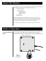
Modes of Operation
Accessing the Menu
Mode
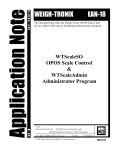
The 6702/6710/6720 powers up in normal weighing mode, ready for weighing operations. You can access the MENU Mode by setting switch 1 shown in figure 1
(Model 6702 & 6710) or figure 2 (Model 6720), to the OPEN or Menu Mode position.
Bottom view of 6710 scale.
Figure 1
6702 & 6710
Switch location
2
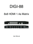
Modes of Operation - Continued
Top view of 6720 scale with platter removed
Figure 2
6720 Switch Location
With switch 1 in the Menu Mode or Open position, there are three modes available
to you. They are as follows:
Diagnostic Mode - used to test areas of the scale’s function
Configuration Mode - used to configure your scale for your application
Calibration Mode - used when calibrating the scale
The structure for these menus is shown in Figure 3. The following page is specific information
about each mode and following that are the step-by-step instructions for accessing them.
- Internal & External Display Selection The 6720 remote display is used for weight only, the ZERO and TEST keys are inoperable
when the internal display is in use. Dip switch 3 select internal or external display keypad
operation.
3
Normal Weighing
Mode
Press the ZERO key to move
in the menu.
Press the TEST key to move
Set switch 1 to
the OPEN position
in the menu.
After making a selection the display generally
returns to the first parameter in the list.
Figure 3
67XX Menu Structure
After choosing donE, the display shows dIAG.
Menu Mode
dIAG
ConF
CAL
60 H
50 H
LB
KILO
7.002
9.995
9.995
15.005
15.005
29.99
30.01
30.01
60.02
60.02
99.95
120.05
2250
34-F
Load
0
What is displayed here depends on what
capacity and unit of measure you’ve chosen
above. You may choose alternate calibration
points by pressing the ZERO key.
Load
10
donE
FiLt
bAUd
Prot
Choose
from
a list of
15 baud
and parity
options
Fast
dISP
Performs
a display
test
rA
rO
Performs Performs
a test
a test
of RAM
ROM
SLO
I/O
Performs
an input/output
test
NCI
donE
ECR
8213
ATT
If scale is placed in a noisy environment
set slow filter to minimize the effects.
divA
Performs
a division
test w/ AZT
divn
donE
Performs
a division
test w/o
AZT
Returns to
dIAG mode
4
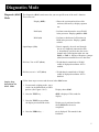
Diagnostics Mode
Diagnostic (dIAG) The diagnostic (dIAG) mode menu lets you test specific areas of the scale’s function.
These areas are:
Mode
Step-by-Step
Instructions for
dIAG Mode
Display (dISP) -
- Shows the version and revision of the
software, followed by a display segment
test.
RAM (rA)
- Performs a non-destructive test of RAM
in the processor. Displays pASS or fAIL.
ROM (rO)
- Performs a checksum of all locations in
ROM in the processor. Displays pASS
or fAIL.
Input/Output (I/O)
- Data is output by the scale and through
the use of a loopback connector the data
is immediately read back into the receive
channel and verified against what was sent.
PASS or FAIL is displayed. Requires a jumper
(short) between transmit & receive data lines.
Division, Test w/AZT (divA)
- Weight data is normalized to 120,000
counts of displayed resolution. AZT is
enabled.
Division, test w/o / AZT (divn)
- Weight data is normalized to 120,000
counts of displayed resolution. AZT is
disabled.
Follow these steps to access and the tests in the dIAG menu.
1. From normal weighing mode , move
switch 1to the Menu Mode or OPEN
position. (See Figures 1 & 2)
2. Press the TEST key. . .
3. Press the TEST key to perform
the display test described earlier. .
4. Press the ZERO key . . .
Display shows dIAG.
dISP is displayed. This stands for
display.
Display test is performed and the
shows dISP after the test is
completed.
rA is displayed. This stands for the
RAM test.
5
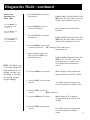
Diagnostics Mode - continued
Step-by-Step
Instructions for
dIAG Mode
Press the ZEROkey to
scroll through lists of
selections.
5. Press the TEST key to perform
the RAM test. . .
6. Press the ZERO key twice to
scroll to the ROM test. . .
Press the TEST key to
make a selection.
If you want to skip a test,
press the ZERO key to
scroll to the next test.
7. Press the TEST key to perform
the ROM test . . .
PASS or FAIL is displayed briefly, then
dISP. If the test fails, contact your local
Weigh-Tronix distributor for service.
rO is displayed. This stands for the
ROM test.
PASS or FAIL is displayed briefly, then
dISP. If the test fails, contact your local
Weigh-Tronix distributor for service.
8. Press the ZERO key three times
to scroll to the I/O test . . . I/O is displayed. This stands for the
Input/Output test.
9. With a loopback connector in
place, press the TEST key to
perform the I/O test. . .
dIAG will flash every
15 seconds during the
high resolution test to
remind you that you
are doing a test and
not seeing normal
weight readings.
10. Press the ZERO key four times . . .
11. Press the TEST key to perform
this test. . .
PASS or FAIL is displayed briefly, then
dISP. If the test fails, check your
connections and / or contact your
local Weigh-Tronix distributor for
service.
divA is displayed. This stands for the
high resolution test with AZT enabled.
The display shows the weight on the
scale at a resolution of 120,000 counts.
12. Press the TEST key to stop
the test. . .
dISP is displayed.
13. Press the ZERO key five times. . .
14. Press the TEST key to perform
this test. . .
divn is displayed. This stands for
the high resolution test without AZT
enabled.
The display shows the weight on the
scale at a resolution of 120,000
counts.
6
Diagnostics - continued
15. Press the TEST key to stop the
the test. . .
16. When you are finished with the
test press the ZERO key six
times, which displays donE,
and press the TEST key. . .
or place switch 1 back to
normal mode to return back
to normal weighing mode.
dISP is displayed.
dIAG is displayed.
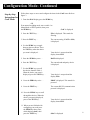
Configuration Mode
The configuration (ConF) mode menu lets you configure your scale to your specific
application needs. The items you can configure are as follows:
Filtering (FiLt)
- Choose between FAST and SLO filtering.
Slow should be chosen in area susceptible
to vibration. Choose FAST filtering for
more stable conditions.
Baud (bAUd)
- Choose a baud and parity from table 1.
Protocol (Prot)
DISPLAY
BAUD
PARITY
12 e
24 e
48 e
96 e
19.2 e
1200
2400
4800
9600
19,200
Even
Even
Even
Even
Even
12 o
24 o
48 o
96 o
19.2 o
1200
2400
4800
9600
19,200
Odd
Odd
Odd
Odd
Odd
12 n
24 n
48 n
96 n
19.2 n
1200
2400
4800
9600
19,200
None
None
None
None
none
- Select the RS-232 communication protocol from below:
NCI - NCI standard
ECR - Cash resister compatible
8213 - 8213 compatible (Sharp)
2250 - 2250 compatible (Swintec)
34-F - 34-MF compatible (Sweda-Mexico)
7
ATT - A T & T compatible
Configuration Mode- Continued
Step-by-Step
Instructions for
ConF Mode
Follow these steps to access and configure the items in the ConF menu. Refer to
figure 3.
1. From the dIAG display press the ZERO key
OR
From normal weighing mode, move switch 1 to
Menu Mode or OPEN position, then press
the ZERO key. . .
ConF is displayed
2. Press the TEST key. . .
FiLt is displayed. This stands for
filtering.
3. Press the TEST key. . .
The current setting, FAST or SLO,
is displayed.
4. Use the ZERO key to toggle
between the two choices. Press
the TEST key when the choice
you want is displayed. . .
Your choice is accepted and the
display shows FILt.
5. Press the ZERO key once. . .
BAUD is displayed.
6. Press the TEST key. . .
The current baud and parity choice
is displayed.
7. Use the ZERO key to scroll
the choices found in Table 1.
When the choice you want is
displayed, press the TEST key. . .
Your choice is accepted and the
display FILt.
8. Press the ZERO key twice. . .
PROT is displayed. This stands for
protocol.
9. Press the TEST key. . .
The current RS-232 communication
protocol is displayed.
10. Press the ZERO key to scroll
through the choices. When the
choice you want is displayed,
press of the TEST key. . .
11. When you are finished with
configuring your scale press
the ZERO key three times,
which displays donE, then
press the TEST key. . .
Your choice is accepted and the
display shows FILt.
dIAG is displayed
8
Calibration Mode
The calibration (CAL) mode menu lets you calibrate your scale. The items in the
calibration menu are as follows:
Line Frequency (50 or 60H)
- Select the AC line frequency you are using.
Pounds/Kilograms (LB or KILO)
- Selects the unit of measure of your calibration test weights.
Capacity (9.995, etc..)
- Select the capacity of your scale.
Follow these steps to calibrate your scale. refer to Figure 3.
Step-by-Step
Instructions for
CAL Mode
1. From the dIAG display press the
ZERO key twice
OR
From normal weighing mode, move
switch 1 to the Menu Mode or
OPEN position, then press the
ZERO key twice. . .
2. Press the TEST key. . .
3. Press the ZERO key to toggle
between the choices. When the
choice you want is displayed, press
the TEST key. . .
4. Press the ZERO key to toggle
between the choices. When the
choice you want is displayed,
press the TEST key. . .
5. Press the ZERO key to toggle
between the choices. When the
choice you want is displayed,
press the TEST key. . .
6. Clear all weight from the scale
platter and press the TEST key. . .
CAL is displayed. This stands for calibration.
50 h or 60 H is displayed. This is the AC line
frequency.
That choice is accepted and LB or KILO is
displayed. This is the unit of measure of
your test weights.
That choice is accepted and a scale capacity
is displayed. Example: 9.995.
That choice is accepted and LOAD 0 is
displayed.
After a brief wait LOAD 10 is displayed .
10 is used only as an example here.
9
Calibration Mode - Continued
7. Place ten pounds of test weights on
the scale and press the TEST key.
8. Press the TEST key. . .
or
9. Return switch 1 to the closed
position. . .
After a brief wait DONE is displayed.
DIAG is displayed.
The scale returns to normal weighing mode.
The scale is now tested, configured and calibrated. It is ready for use in your application.
Error Codes
Any system errors detected by the scale will be displayed as the letter E followed by
a two-digit error code. Press the TEST key to continue operation. If a calibration
error occurs the only way to clear it is by recalibrating the scale.
The error codes are broken down into two hexadecimal numbers, with each bit
defining a single error condition. The error codes are defined as follows:
Most Significant
Digit
Least Significant
Digit
8 4 2 1
8 4 2 1
Reserved
Calibration error
For
ROM error
Future
RAM error
Use
Serial EE PROM error
10
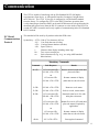
Communication
The 67XX is capable of interfacing with an EIA Standard RS-232, full duplex,
asynchronous, smart device, or 4-bit parallel interface for output of weight data to
an ECR device. The 67XX 15 pin style is configured as a 4-Bit Parallel standard
from the factory. To configure the 67XX to the RS-232 interface operation, there
is a dip shunt jumper located at JMP 2 on the main PCB that needs to be positioned with
shortening pins placed away from the DE-15 connector or to the inside of the PCB. The
second uses a DE-9 connector and is only capable of communicating in the EIA Standard
RS-232 method.
NCI Serial
Communications
Protocol
This standard will be used by all products other than ECR scales.
Symbol Key: <ETX> End of Text character (03) hex
<LF> Line Feed character (0A hex)
<CR> Carriage Return character (0D hex)
<SP> Space (20 hex)
x
Character from display including minus sign.
hh. . . Two or more status bytes
uu
Units of measure (lb, kg, oz, g, etc. using ANSI standard
abbreviations)
Mandatory Commands
Command
Scale Response
Results
W<CR>
<LF>xxxx.xxuu<CR>
<LF>hh...<CR><ETX>
or
Returns decimal weight with units
plus scale status.
<LF>xxxxxx<CR>
Returns contents of display
<LF>hh...<CR><ETX>
(other than wt) & scale status
S<CR>
<LF>hh...<CR><ETX>
Returns to scale status
Z<CR>
<LF>hh...<CR><ETX>
Scale is zeroed, returns status.
H<CR>
<LF>xxxx.xxuu<CR>
<LR>hh...<CR><ETX>
or
Returns decimal wt in 10x with
units plus scale status.
<LF>xxxx.xxoz<CR>
<LF>hh...<CR><ETX>
Returns lb-oz wt in 10X with units
plus scale status(if required by
application).
or
all else
<LF>xxxxxx<CR>
<LF>hh...<CR><ETX>
Returns contents of display
(other than wt) & scale status
<LF>?<CR><ETX>
Unrecognized command
11
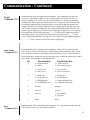
Communication - Continued
Weight
Command ("W")
Implementation of this command will be mandatory. This command causes the scale
to return to a WYSIWYG (What you see is what you get) of its display when it is in
normal weighing mode. That is, the scale will send whatever is showing on its display
including any minus sign/and or decimal point. If it is weight, the units of measure will
be returned in addition to the displayed weight. For decimal weight, the length of the
weight field will be equal to the length of the scale's display plus two for the units, e.g.,
("lb"). Units of measure will appear in their ANSI standard abbreviation form ("lb" for
pounds, "kg" for kilograms, etc.) If the scale is displaying all upper bars ("over capacity"),
the weight field will be filled with carets("^^^^^^"). If the scale is displaying all lower
bars (under capacity), the weight field will be filled with underscores ("
"). If the
scale is displaying middle bars (zeroing error), the weight field will be filled with dashes
("- - - - - -"). These examples are for scale with a 6-digit display.
Scale Status
Command ('S')
Implementation of this command will be mandatory. There will be at least two status
bytes. If bit 6 of the second status byte is set then there will be a third byte. Bit 6 of each
byte will indicate whether or not another status byte follows. The bit will be clear (0) in
the last status byte. At this time only the first three bytes are defined. Others may be added
in the future. The status bits are defined as follows:
Bit
Zero
Command ('Z')
First Status Byte
Second Status Byte
0
1 = Scale in motion
0 = Stable
1 = Under capacity
0 = Not under capacity
1
1 = Scale at zero
0 = Not at zero
1 = Over capacity
0 = Not over capacity
2
1 = RAM error
0 = No RAM error
1 = ROM error
0 = No ROM error
3
1 = EEPROM error
0 = No EEPROM error
1 = Faulty calibration data
0 = caliobration data okay
4
Always 1
Always 1
5
Always 1
Always 1
6
Always 0
1 = Byte follows
0 = Last byte
7
Parity
Parity
Implementation of this command will be mandatory. If zeroing criteria are met, the scale
will is zeroed. In any case, scale status is returned.
12
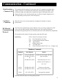
Communication - Continued
High Resolution
Command ('H')
This command will be optional. It is the same as the "W" command except that when
weight is returned, it is returned with ten times the scale's displayed resolution. Thus,
for decimal weight, the length of the weight field is equal to the length of the scale's
display plus three or four, and for pounds-ounce it will be the display length plus five
or six (depending on the presence of a decimal point.)
Undefined
Commands
When the scale receives an unrecognised or unsupported command, it returns a
question mark.
ECR Serial
Communication
Protocol
The ECR serial communication protocol adheres to the pre-existing "standard" for ECR
scales. It also includes optional commands and the new scale status bit definitions
(described in the general protocol) as extensions which do no affect backwards compatibility.
This standard will be used by all other products other than ECR scales.
Symbol Key:
<ETX>
<LF>
<CR>
<SP>
x
hh
uu
End of Text character (03 hex)
Line Feed character (0A hex)
Carriage Return character (0D hex)
Space (20 hex)
Weight numeric digit.
Two status bytes
Units of measure (LB, KG, OZ, G, etc.., all upper case)
Mandatory Commands
Command
Scale Response
Results
W<CR>
<LF>xxx.xxuu<CR>
<LF>Shh<CR><ETX>
or
Returns decimal weight with units
plus scale status.
<LF>Shh<CR><ETX>
Scale status only if wt <0, in
motion or out of capacity, or
zero error.
S<CR>
<LF>Shh<CR><ETX>
Returns to scale status
Z<CR>
<LF>Shh<CR><ETX>
Scale is zeroed, returns status.
all else
<LF>?<CR><ETX>
Unrecognized command
Scale bits will be the same as for the general protocol.
13
Communication - Continued
Serial Data
Transmission
Modem control lines
will not be supported
for RS-232.
Baud Rates:
1200, 2400, 4800, 9600, or 19.2K
Word Length:
10 Bits
1 Start, 7 Data, 1 Parity, 1 Stop
Parity
Even, Odd, or None
The scale is DTE
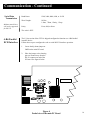
4-Bit Parallel
ECR Interface
The 15 pin version of the 67XX is shipped configured to function as a 4-Bit Parallel
interface device.
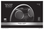
Follow these steps to configure the scale to serial RS-232 interface operation:
1.
Locate the dip shunt jumper at
JMP2 on the main PC board.
2.
Place the jumper so the shorting
pins are located away from the
DE-15 connector at end of the
PC board. See figure 4 below.
Figure 4
Partial view of the main PC Board
14
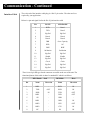
Communication - Continued
Interface Cable
The scale end of the interface cable plug is a DA 15 pin socket. The other end is as
required by your application
Below is a pin and signal list for the DA 15 pin interface cable
Pin
RS-232
4-Bit Parallel
1
2
RXD
TXD
Data 1
Data 2
3
Sig Gnd
Sig Gnd
4
Data 4
Data 4
5
Data 8
Data 8
6
DSR
Over Capacity
7
DTR
NC
8
BHZ
BHZ
9
/In Motion
/In Motion
10
Sig Gnd
Sig Gnd
11
/Enable
/Enable
12
Sig Gnd
Sig Gnd
13
Clock
Clock
14
Sig Gnd
Sig Gnd
15
Sig Gnd
Sig Gnd
There is one 9 pin DE type female connector accessible at the rear of the unit. The
functional pinout of this cable is that of a standard PC which is as follows:
DE-9 Female
Scale
DE-9 Male
Host
Pin
Name
Direction
Name
Direction
1
JMP 1
-
DCD
IN
2
TXD
OUT
RXD
IN
3
RXD
IN
TXD
OUT
4
JMP 1
-
DTR
OUT
5
SG
-
GRD
-
6
JMP 1
-
DSR
IN
7
JMP 2
-
RTS
OUT
8
JMP 2
-
CTS
IN
9
NC
-
RI
IN
15
3990 Brickway Blvd.
Santa Rosa, CA 95403
Telephone 1 707-527-5555
1 800-982-6622
Facsimile 1 707-579-0180
1 800-847-6743
01/20/98 PN 7424-14787C Printed in USA