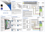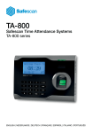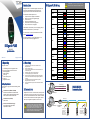
1
Introduction
DIGIgarde PLUS is a combined fingerprint and smart card
reader with integral backlit keypad providing User ID,
fingerprint, PIN and smart card authentication modes.
Label
Wire Colour
Signal
Description
Black
0V
Power GND
Red
+12V
Power Input
Black
GND
GND
White
WD0-IN
Wiegand Input, Data 0
Green
WD1-IN
Wiegand Input, Data 1
Yellow
WD0-OUT
Wiegand Output, Data 0
White
WD1-OUT
Wiegand Output, Data 1
Black
GND
Wiegand GND
The user manual can also be downloaded from the TDSi
website: http://www.tdsi.co.uk
Blue
LED
LED
White
SENSOR
Door Sensor power
For technical assistance, contact TDSi Support on +44
(0)1202 724998 or email [email protected].
Black
GND
Door Sensor ground
Grey
BUTTON
Egress button
Blue
NO1
Normally Open
Red
COM1
Common
Yellow
NC1
Normally Closed
Orange
ALARM NO2
Alarm (Normally Open)
Green
ALARM COM2
Alarm (Common)
Blue
RS-485A-2
RX+, RS-485-2 level
Yellow
RS-485B-2
RX-, RS-485-2 level
Black
RS-232 0V
RS-232 0V
Grey
RS-232 RX
Receive Data, RS-232C level
Purple
RS-232 TX
Transmit Data, RS-232C level
Blue
RS-485A-1
RX+, RS-485-1 level
Yellow
RS-485B-1
RX-, RS-485-1 level
Black
GND
RS-485 GND
Brown
RS-485RES
Brown
RS-485RES
Link wires to provide termination
resistor for this unit (see below)
Power
This Quick Start Guide explains how to:
1. Unpack the unit and prepare for installation.
2. Mount the unit using the supplied fixing kit.
3. Connect the unit.
4. Set up an administration account.
5. Enrol a user and record their fingerprint.
6. Verify a user and scan a fingerprint.
WG IN
Please read the user manual (on the accompanying CD) for
detailed information about any of these steps.
WG OUT
Lock
DIGIgarde PLUS
5002-0455
Quick Start Guide
Alarm
RS485-2
QS015 Issue 1
Copyright © 2012 TDSi
1. Unpacking
This pack contains:
A TDSi DIGIgarde PLUS fingerprint reader
CD with operating software and manual
Mounting template
Cable assembly
Ferrite ring
Tool for security screw
Fixing kit
Suppression diode
Cabling Requirements
You will need to supply and install the following cables
to the unit:
Communications (RS232 or RS485)
Screened cable: Belden 9729, Belden 9502,
OS2P24, OS2P22, Alpha 5902, Alpha 5094 or
other equivalent screened alarm cable.
Communications (TCP/IP)
Cat5 or Cat6
Access Controller/Power Supply
6-core Belden 9730, Belden 9503,
Alpha 5096 or OS6C24
CAUTION! Ensure that the supplied ferrite ring is
fitted to the unit’s cable bundle for EMC protection.
DIGIgarde PLUS Wiring
2. Mounting
1.
2.
3.
4.
5.
6.
7.
8.
Unfasten and remove the screw on the base of the
DIGIgarde PLUS.
Remove the back cover.
Use the mounting template to mark out the drill holes and
cable access point.
Drill the two 6mm holes to a depth of 35mm.
Push the supplied plugs into the drill holes.
Fasten the unit's back plate to the wall using the supplied
screws. Ensure that the anti-tamper magnet is positioned
correctly.
Feed the cable into the wall and hook the top of the
DIGIgarde PLUS onto the mount.
Fit the supplied ferrite ring around the wire bundle for EMC
protection.
RS232
RS485-1
RS485RES
RS232 RX (grey)
PC
RS232/RS485
Communications
RS232 TX (purple)
3. Connections
DIGIgarde PLUS can be connected to other devices (access
control units, lock, door sensor, alarm, host PC etc) through
the colour-coded and labelled connection cables. In addition
to the connections described in the table opposite, there is
also a pre-configured POI-capable, RJ-45 connector.
RS232 0V (black)
RS232 port
PC
RS485-1 (blue)
RS485-1 (yellow)
CAUTION! Lock strike suppression devices MUST be
fitted directly across all inductive loads such as lock
strikes, secondary relays and automatic door openers).
Failure to adhere to this notice will invalidate the
warranty of this product and may result in irreparable
damage to it and other connected equipment.
RS232 port
RS232/RS485
converter
On first unit, short
two brown wires
in RS485REM
bundle if converter
does not provide
termination resistor
On last unit, short
two brown wires
in RS485REM
bundle to provide
termination resistor
Unit 1
Unit 2
Unit 3
4. Standalone Use
5. Connecting to an ACU
(a) Enrolment
(a) Connections
To enrol a user, press the Menu button.
Data 0
Data 1
0V
LED
If you have registered an Administrator, Manager or Enroller account,
you are prompted to verify your identity (see Step c). After you have
done this, press the Menu button again.
ACU
Press the OK button to select the User Manage menu option. Select
Enrol User and follow the on-screen prompts to:
WG-OUT
+12V
0V
Power
1. Select a user ID.
2. Choose the enrolment method:
fingerprint (FP), password (Pwd) or both (FP & Pwd).
3. Scan a finger three times and/or enter a 5-digit password or PIN.
4. Repeat the procedure to provide the user with a backup fingerprint.
5. Save the template.
TCP/IP
Network
(required for template distribution)
(b) Configure Reader Format
Choose whether you want to use Wiegand format or Magnetic Clock and Data Format.
(b) Setting up Admin Accounts
The first time the DIGIgarde PLUS is powered up, there are no user accounts. Your first step should
be to create one or more protected administrator accounts.
1. Press the Menu button.
2. Use the ▼ to select Options
and press the OK button.
3. Press the ▼ key to select
Data Out Type and then
press the OK button.
4. Use the ▲▼ keys to select
either WG Type (Wiegand) or
MAG Type (Magnetic) mode.
DIGIgarde PLUS recognises three admin levels:
Enroller
Manager
Admin
To set up an Admin, Manager or Enroller account:
1.
2.
3.
4.
Press the Menu button.
Press the OK button to select the User Manage menu option.
In the User Manage menu, use the ▲▼ keys to select the Enrol Admin option.
Use the ▲▼ keys to select the enrolment method: fingerprint (FP), password (PWD) or both (FP
& Pwd). Press the OK button.
5. The Admin Accredit screen is displayed. Use the ▲▼ keys to choose the management role.
6. Follow the on-screen prompts to scan a finger three times and/or enter a password.
(c) Configure Wiegand Mode
If you are using Wiegand mode, you will need to set up the Wiegand data format.
1. Press the Menu button.
2. Press the ▼ key to select
Options and press the OK
button.
3. Press the OK button to
select System Opt.
4. Use the ▼ key to select
Wiegand and press the OK
button.
(c) Verification
The verification process involves one or more of the
following steps:
Keying in your user ID
Scanning the fingerprint recorded during enrolment
Entering your password
Reading of a smart card
5. Use the ▼ key to select
Output Setting and
press the OK button.
6. Select Output Format and
press the OK button.
7. Use the ▲▼ keys to select
the required format, for
example: WG26 without ID.