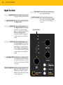
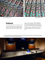
1
Console 1 User Manual Supporting VST/VST3/AU/AAX Native. Rev. Aug 25, 2015 Softube User Manual © 2007-2015. Amp Room, Console 1 is trademarks of Softube AB, Sweden. Softube is a registered trademark of Softube AB, Sweden. All visual and aural references to the Valley People Dyna-mite, Trident A-Range, Tonelux and Tilt are trademarks being made with written permission from PMI Audio. The Tonelux and Tilt logo, the Valley People, Dyna-mite and associated logos, and the Trident, A-Range and Triangle logo are trademarks of PMI Audio Group, used under license. Tube-Tech is a registered trademark of Lydkraft ApS, Denmark. EMI and Abbey Road are trademarks of EMI (IP) Limited. REDD, RS127 and RS135 are trademarks of EMI (IP) Limited. SSL, Solid State Logic, SL 4000 E, XL 9000 K are all trademarks of Solid State Logic, UK, used with written permission. All specifications subject to change without notice. All Rights Reserved. Other company and product names mentioned herein are trademarks of their respective companies. Mention of third-party products is for informational purposes only and constitutes neither an endorsement nor a recommendation. Softube assumes no responsibility with regard to the performance or use of these products. Softube products are protected by patents SE526523 and SE525332, and related patents/patent applications, including WO06054943, US11/667360, US20040258250, EP1492081, EP1815459, and JP2004183976. Your rights to the software are governed by the accompanying software license agreement (End User License Agreement). Disclaimer Every effort has been made to ensure that the information in this manual is accurate. However, there are a chance that we have made mistakes, and we hope that you understand that we are only humans. Please let us know about the mistake, and we’ll fix it in the mix (or in the next version of this manual). Support On the Softube website (www.softube.com) you will find answers to common questions (FAQ) and other topics that might interest you. Support questions can be posted at http://www.softube.com, where we will help you as fast as we can! Web: www.softube.com E-mail: [email protected] Phone: +46 13 21 1623 (9 am – 5 pm CET) CONSOLE 1 USER’S GUIDE | Contents 1 Introduction and overview 5 The SSL SL 4000 E Channel. . . . . . . . . . . . . . . 5 Console 1 Compared to Traditional Mixers. . . . . . . . . 6 2 Getting started 9 Setting Up Your First Console 1 Session . . . . . . . . . . 9 Input Section. . . . . . . . . . . . . . . . . . . . . 16 Shape Section . . . . . . . . . . . . . . . . . . . . 17 Equalizer Section. . . . . . . . . . . . . . . . . . . 18 Compressor Section. . . . . . . . . . . . . . . . . . 20 Output Section. . . . . . . . . . . . . . . . . . . . 21 3 4 Working with Console 1 23 Track Selection. . . . . . . . . . . . . . . . . . . . On-Screen Display. . . . . . . . . . . . . . . . . . . The Input Section. . . . . . . . . . . . . . . . . . . Shape. . . . . . . . . . . . . . . . . . . . . . . . Equalizer. . . . . . . . . . . . . . . . . . . . . . . Compressor. . . . . . . . . . . . . . . . . . . . . The Output section. . . . . . . . . . . . . . . . . . Understanding Solo Safe. . . . . . . . . . . . . . . 24 24 26 28 30 32 34 35 Useful Functions 37 Select All Tracks . . . . . Create a Group . . . . . . Duplicate Track Settings. . Load Presets . . . . . . . Save Preset . . . . . . . . . . . . . . . . . . . . . . . . . . . . . . . . . . . . . . . . . . . . . . . . . . . . . . . . . . . . . . . . . . . . . . . . . . . . . 37 37 39 40 42 5 6 Organizing your presets. . . . . . . . . . . . . . . . Default Presets. . . . . . . . . . . . . . . . . . . . History. . . . . . . . . . . . . . . . . . . . . . . Renaming/Rearranging Tracks. . . . . . . . . . . . . Set Auto Display Delay. . . . . . . . . . . . . . . . . Using Console 1 Without the Hardware. . . . . . . . . Automation . . . . . . . . . . . . . . . . . . . . . 42 43 44 45 46 46 46 Customizing the Channel Strip 47 Loading Other Channel Strips and Effects . . . . . . . . Changing the Order of the Sections . . . . . . . . . . . Using External Sidechain Signals. . . . . . . . . . . . View Options. . . . . . . . . . . . . . . . . . . . . 47 48 48 50 Solid State Logic XL 9000 K 51 VHD model included. . . . . . . . . . . . . . . . . 52 Extended gate and compressor options. . . . . . . . . 52 Background . . . . . . . . . . . . . . . . . . . . . 53 7 Specifications, Requirements and Troubleshooting 55 Block Diagram. . . . . . . . . . . . . . . . . . . . 56 Troubleshooting . . . . . . . . . . . . . . . . . . . 57 Hardware Specifications. . . . . . . . . . . . . . . . 58 8 END USER LICENSE AGREEMENT lix iii | 5 1 Introduction and overview Softube Console 1 is a new type of audio mixer. It is used together with your favorite digital audio workstation (DAW), and just like a traditional mixing console, you can route any or all DAW tracks to Console 1 and mix them from within that system. This gives you access to Console 1’s world class sounding effects sections and lets you control everything from the hardware unit, using physical knobs and buttons. So what Console 1 gives you is the great sound that has made Softube world famous, in addition to a tactile and intuitive workflow that speeds up your mix work substantially compared to mouse mixing on the computer. The SSL SL 4000 E Channel Included in your purchase is Softube’s model of a Solid State Logic SL 4000 E, one of the most famous and coveted mixing consoles in the world. SL 4000 E consoles have been installed in hundreds of the world’s leading studios, and it is said that Solid State 6 | INTRODUCTION AND OVERVIEW Logic’s 4000 series have been used on more platinum selling records than all other console models combined! This is for good reason. The SL 4000 E has a signature sound that is transparent enough to work for all music styles, but still adds its touch of luxury. Things simply sound like a record when they’ve been run through the SL 4000 E. With Console 1, you get the famous black knob E242 equalizer, the classic channel compressor, the very musical gate/expander and the sweet high/low cut filters from the SL 4000 E channel. We also modeled the unique harmonics, distortion and nonlinearities you get from running the SL 4000 E into overdrive. Controlled by Console 1’s Drive knob, you can use it subtly on all channels to glue the mix together like a slightly overdriven SL 4000 E does, or not so subtly to add edge and presence to selected sounds. In addition, you get Softube’s unique Transient Shaper, which is not modeled off the Solid State Logic SL 4000 E or any other unit for that matter. Read more about Transient Shaper in “Shape” in Chapter 4. Softube’s model of the Solid State Logic SL 4000 E channel is only available as part of the Console 1 system and not as a single plug-in. Softube will continuously release more channel strip models to be used with Console 1, that can be purchased separately. Console 1 Compared to Traditional Mixers To understand what Console 1 is, it may be helpful to compare it to existing mixer types. There are quite a few differences between Console 1 and most traditional mixers—both digital and analog ones. First of all, Console 1 is strictly made for mixing, it’s not a recording mixer with microphone preamplifiers. With Console 1, you have access to one channel at the time, the one you have selected with the corresponding channel selector button on the hardware unit. This gives the hardware unit a small footprint, but still offers direct access to more functions and effects per channel compared to most physical mixing consoles—as mentioned in the previous section, equalizer, compressor, distortion, gate, high and low cut filters and our Transient Shaper. All Console 1 settings are saved with your DAW session for total recall, and each parameter can be automated using the hardware knobs. You can open a DAW session mixed using Console 1 without having the Console 1 hardware connected, and you can even adjust settings using the mouse if you happen to be away from your Console 1 hardware. Solid State Logic SL 4000 E was introduced in 1980 and is to this day used in a large number of high end studios all over the world. Softube’s model includes the most sought after equalizer version, the black knob E242. Furthermore, the Console 1 hardware has no on-board DSP power, all the audio processing takes place within your computer. This has several advantages compared to a physical mixer, such as portability, lower cost and no need for an external power supply—the Console 1 hardware is USB CONSOLE 1 USER’S GUIDE | powered. The Console 1 software is also very CPU efficient, but please refer to “General requirements” on page 55 to see if your computer is powerful enough to use with Console 1. And obviously, most mixers are contained in one single hardware unit. The Console 1 system consists of three different components that work in tight integration: the hardware, the On-Screen Display and the DAW plug-in. One might say there is also a fourth component, namely the channel strip or single effect you have loaded into the separate Console 1 tracks. If you’re new to Console 1, the channel strip will be the SSL SL 4000 E that is included in the purchase. There will be more plug-in channel strips for Console 1 such as that one, that can be purchased separately. And you can also load other Softube plug-ins into the system. See “Loading Other Channel Strips and Effects” in Chapter 6 of this manual. 7 | 9 Nobilis Audio, Germany 2 Getting started In order to install the required software and activate your license, first make sure your computer has internet access. Use any browser to visit the page www.softube.com/console1-install Here, you will be guided through all the necessary steps. You will be asked to enter the unique license code printed on the Quick Start guide that is enclosed in the Console 1 shipping box. Setting Up Your First Console 1 Session When you have gone through the registration process on Softube’s web site, you are ready to set up your basic Console 1 session. You may want to save this as a template session in your DAW, so you will not have to do this for every new piece of music you start working on. Please refer to your DAW’s manual on how to save a template session, as well as any other steps mentioned below that refer to actions in your DAW. 1. Connect the Console 1 hardware to an unoccupied USB port on your computer. The Softube logo in your computer’s control panel will turn from grey to black. 2. Launch your preferred digital audio workstation (DAW) application. Console 1 runs with any host that supports VST2, VST3, AAX and Audio Units plug-in formats 3. Launch an empty session in your DAW. 4. Insert the Console 1 plug-in on as many tracks as you like. We recommend inserting it on all single tracks, aux channels and buses. The audio on any track where you have inserted the Console 1 plug-in will now be 10 | GETTING STARTED routed into the Console 1 system and back to the same DAW channel. See next section for setting the correct track name and number. Track Name and Number Many DAW hosts support automatic transfer of track name and number from the DAW host tracks to the corresponding Console 1 tracks. This means that any name you have given a track in the DAW host automatically appears on the corresponding track in the Console 1 mixer. Similarly, if the DAW host supports automatic transfer of track number, the number of the DAW track will be the same as the corresponding track in Console 1, so the track layout will be the same in Console 1 as in your DAW. This in turn means that if you decide to rearrange the track order in your DAW, this also gets reflected in the Console 1 mixer. In order to verify this, you can open the Console 1 plug-in window on any channel in your DAW. In the lower right part of this window, you will see either “Auto” or “Manual”. “Auto” indicates that the track name and number is automatically transferred from your DAW to Console 1. In this case, you will now be able to open Console 1’s On-Screen Display (by pushing the Display On button in the top left corner of the hardware) and see all the tracks laid out and named just as they are in your DAW session. However, some DAW hosts do not support automatic transfer of track name and number from the host to Console 1. In the case of Pro Tools and Logic Pro, these support automatic transfer of track name, but not number. This is the “Manual” case, which will be indicated in the lower right part of the Console 1 plug-in window. In this case, you will need to manually select to which Console 1 track the Console 1 plug-in routs the DAW channel’s audio, and possibly also manually enter the track name for it to display in the Console 1 system. If your preferred DAW does not support automatic transfer of track number: When a Console 1 plug-in is instantiated on a DAW track, it will by default be placed on the lowest available track number. This means that it can be a good idea to launch the Console 1 plug-ins by starting on DAW track 1, which will then be placed on Console 1 track 1, then move on to DAW track 2, which will be placed on Console 1 track 2 (because this is now the lowest available track), etc. This should save you from most of the manual work of placing the Console 1 tracks in a way that corresponds to how they are laid out in the DAW. CONSOLE 1 USER’S GUIDE | Follow these steps to set the track name: 1. Open the Console 1 On-Screen Display. 2. Open Settings by pressing Shift and track selector 20 (Settings). Scroll down to “Rename Tracks” and click Solo/OK. 3. Select the first track with the track selector buttons, and enter the name in the dialog window. Hit OK. 4. Select the next track, and do the same thing. Follow these steps to place a certain Console 1 track on a certain track number: 1. Open the Console 1 On-Screen Display. 2. Open Settings by pressing Shift and Track Selector 20 (Settings). Scroll down to “Rearrange Tracks” and click Solo/OK. 3. Select which track you want to move using the track selector buttons. 4. Select where you want to put it. 5. Select the next track you want to move, and repeat until you’re done! See details in “Renumber/rearrange Tracks” and “Rename Tracks” on page 45. You can only put 1 instance of the Console 1 plug-in on each track if the DAW supports automatic track numbers. 11 12 | GETTING STARTED Solo Safe on Aux Channels and Buses As mentioned above, we recommend that you insert the Console 1 plug-in on all your DAW channels, including single tracks, aux channels and buses. But in order for Console 1’s Solo function to work as expected, you should set aux channels, effects send channels, subgroup buses and the master bus—essentially, any channels in your DAW mixer that are not single audio or software instrument tracks—to Solo Safe. If you are using an aux channel for the incoming sound of a Rewire sound source, such as Propellerheads Reason, this can however be viewed as an instrument track. We consequently recommend you do not set this to Solo Safe. See “Understanding Solo Safe” on page 35 if you’re interested in why this setting is needed for Console 1’s Solo function to behave as expected. Otherwise, simply follow these steps: • Open the Console 1 plug-in on all aux channels (except Rewire aux channels that handle incoming sound signals), effects channels, subgroup buses and the master bus in your DAW. • Activate Solo Safe setting by clicking this button in the plug-in window. Any time you press Solo on the Console 1 hardware, the text ”Solo safe” will appear in the OnScreen Display above any channel that has been set to Solo safe. CONSOLE 1 USER’S GUIDE | Track Number This is automatically set to correspond to the DAW track, in DAWs that support this function. If your DAW does not support automatic transfer of the track number, click the number set this manually. You can also press Shift + 20 (Settings) to to rename ro renumber tracks from the On-Screen Display. That is the preferred method, and is a lot easier to use. Track Name This is automatically set to correspond to the DAW track, in DAWs that support this function. If your DAW does not support automatic transfer of the track name, click the name to set this manually. Track Number 2 Drums OH Track Name Show Knobs Click to open an interface that resembles the Console 1 hardware. Here, you can adjust the settings using a computer mouse. Solo Safe Clicking this excludes the track/channel from Solo. When another track is set to solo, Solo Safe channels will not be silenced. This option is recommended for all aux channels, subgroups and the master bus. Auto or Manual Indicates if your DAW sup- ports automatic transfer of track number and name, or if you need to set this manually. Show Knobs Show Knobs Solo Safe AUTO Solo Safe Auto or Manual Track Name/Number Indicator 13 14 | GETTING STARTED Display Auto Display On Load Compressor Load EQ Load Shape Load Strip History Page Up Page Down Track Selector Buttons Settings Group External Sidechain All Order Display On Toggles Console 1’s On-Screen Display on and off. Hold Shift and push Display On to select different view modes. Display Auto Sets the On-Screen Display behavior to automatic mode. In this case, the display pops up every time you change a setting, and automatically goes away a few seconds after your latest adjustment. Page Up, Page Down Select which bank of tracks the 20 channel selector buttons control. You can have a virtually unlimited number of banks and tracks. The Page Up LED will light up if there are tracks on a page above the current, and vice versa with the Page Down LED. Track selector buttons Select the channel you want to adjust, of 1-20 (or 21-40, 41-60 etc, depending on what page you selected with the Page Up and Page Down buttons. The selector buttons for tracks 1-5 and 20 have alternate functions, accessible by holding Shift. Load Strip Selector button for track 1 (or 21, 41, 61 etc, depending on what page you are on). Hold the Shift/Fine Adjust button to select a new channel strip to load into the selected track (if you have more than one Console 1 compatible channel strip). CONSOLE 1 USER’S GUIDE | Load Shape Selector button for track 2 (or 22, 42, 62 etc, depending on what page you are on). Hold the Shift/Fine Adjust button to select a new Shape plug-in to load into the selected track (if you have more than one Console 1 compatible plug-in that is suitable for the Shape section). Load EQ Selector button for track 3 (or 23, 43, 63 etc, depending on what page you are on). Hold the Shift/Fine Adjust button to select a new equalizer to load into the selected track (if you have more than one Console 1 compatible equalizer). Load Compressor Selector button for track 4 (or 24, 44, 64 etc, depending on what page you are on). Hold the Shift/Fine Adjust button to select a new compressor to load into the selected track (if you have more than one Console 1 compatible compressor). History Selector button for track 5 (or 25, 45, 65 etc, depending on what page you are on). Hold the Shift/Fine Adjust button to activate the History function and undo your actions. Settings Selector button for track 20 (or 40, 60, 80 etc, depending on what page you are on). Hold the Shift/Fine Adjust button to enter the Settings menu. All Press and hold to select all tracks at once. Any adjustments made while you hold this will affect all tracks. Press and hold together with Group button to duplicate settings from one track to another, or several others. Group Press and hold while you select two or more tracks to form a group. Hold together with All button to duplicate settings from one track to another, or several others. Order Changes the order of the three main effects sections. Default state is Shape into equalizer into compressor (S→EQ→C). Press repeatedly to toggle between this state, or shape, compressor and equalizer (S→C→EQ) or equalizer, shape and compressor (EQ→S→C). External Sidechain Determines whether an incoming external sidechain signal should have no effect (Off ), be routed to the compressor sidechain (To Comp) or to the sidechain of the gate part in the Shape section (To Gate). 15 16 | GETTING STARTED Input Section Input Gain Adjusts the gain of the incom- ing signal of the selected track. Phase Invert Inverts the phase (polarity) of the selected channel. Preset/Save preset Calls up the Presets menu. Press this while holding Shift to save the current settings as a preset. Input Gain meter Displays the signal level after the Input Gain. High Cut Sets the cutoff frequency of the High Cut filter. Turn fully clockwise to bypass entirely (leave the signal intact). When Filters to Compressor is activated, the filter is applied to the compressor’s sidechain signal. Low Cut Sets the cutoff frequency of the Low Cut filter. Turn fully counterclockwise to bypass entirely (leave the signal intact). When Filters to Compressor is activated, the filter is applied to the compressor’s sidechain signal. Fine Adjust/Shift Hold while you adjust a knob to make the parameter change in smaller increments, or to access the extra functions labeled in orange. Filters to Compressor Shifts the High and Low Cut filters from their default state (affecting the audio signal) to affecting the side-chain signal of the compressor. Input Gain Meter CONSOLE 1 USER’S GUIDE | Shape Section Shape activation Activates or bypasses the Shape section. Shape section meter Displays the level changes caused by the Shape section. Gate Sets the threshold level of the gate. Gate Release Sets the release time of the gate. Hard Gate Toggles between Hard Gate and Soft Gate settings. Sustain Turned clockwise from its center position, lengthens the sustain of the signal. Turned counterclockwise from its center position, shortens the sustain of the signal. Punch Turned clockwise from its center position, makes transients stronger. Turned counterclockwise, makes transients softer. Shape activation Shape section meter 17 18 | GETTING STARTED Equalizer Section EQ activation Activates or bypasses the equalizer section. EQ activation Low Band Cut/Bell/Shelf Sets the operating mode of the equalizer’s low band. Frequency Sets the operating frequency of the equalizer’s low band. Low Gain Turned clockwise from its center position, boosts the gain of the equalizer’s low band. Turned counterclockwise from its center position, cuts the gain of the equalizer’s low band. Low Mid Band Q Sets the width of the equalizer’s low mid band. Frequency Sets the operating frequency of the equalizer’s low mid band. Low Mid Gain Turned clockwise from its center position, boosts the gain of the equalizer’s low mid band. Turned counterclockwise from its center position, cuts Low Band Low Mid Band CONSOLE 1 USER’S GUIDE | the gain of the equalizer’s low mid band. High Mid Band Q Sets the width of the equalizer’s high mid band. Frequency Sets the operating frequency of the equalizer’s high mid band. Q (Width) Cut/Bell/Shelf High Mid Gain Turned clockwise from its center position, boosts the gain of the equalizer’s high mid band. Turned counterclockwise from its center position, cuts the gain of the equalizer’s high mid band. Frequency High Band Cut/Bell/Shelf Sets the operating mode of the Gain equalizer’s high band. Frequency Sets the operating frequency of the equalizer’s high band. High Gain Turned clockwise from its High Mid Band High Band center position, boosts the gain of the equalizer’s high band. Turned counterclockwise from its center position, cuts the gain of the equalizer’s high band. 19 20 | GETTING STARTED Compressor Section Compressor activation Activates or bypasses the compressor section. Gain Reduction meter Displays the gain reduction caused by the compressor. Ratio Sets the compressor’s ratio. Attack Sets the compressor’s attack time. Parallel Dry/Wet Sets the relative level of the compressed and uncompressed signal. Release Sets the compressor’s release time. Threshold Sets the compressor’s threshold. Compressor activation Gain Reduction meter CONSOLE 1 USER’S GUIDE | Output Section Drive Sets the level of the Drive/ distortion function. Turn fully counterclockwise to bypass. Output level meter Displays the output level of the signal that will be routed back to the DAW channel. Drive Character Sets the Drive/distortion character. Pan/Balance Sets the left-right placement of mono-to-stereo tracks, or the balance between left and right channels for stereo tracks. Pan is disabled for mono tracks. Solo/OK Sets the selected tracks in Solo mode (all other channels are silenced, with the exception of tracks that have been set to Solo Safe in the Console 1 plug-in). In menus and dialog windows, the Solo button works as an ”OK” button and confirms your choice in a currently opened menu. Mute/Cancel Silences the selected track. In menus and dialog windows, the Mute button works as a ”Cancel” button and cancels your choice in a currently opened menu. Volume/Select Sets the output volume of the selected track. When Shift is pressed and held, use this knob to scroll in menus. Output level meter 21 | 23 Hammersnail Sonic Research, London, UK 3 Working with Console 1 Console 1 has been designed to not only give you world class sound, but also extreme ease of use. Once you have everything set up, the basic workflow of Console 1 is as follows • Select a track by pressing the corresponding Track Selector button. • Use the knobs to adjust the settings. • Select another track. • Adjust the settings. • Repeat until your mix is great. With that said, there are of course a few more details to look into. We will start by looking into track selection and handling, and then move on to a walkthrough of Console 1’s effects sections. 24 | WORKING WITH CONSOLE 1 Track Selection The DAW tracks where you have initiated the Console 1 plug-in will be routed to the corresponding Console 1 track, as set in the Console 1 plug-in (See “Track Name and Number” on page 10). Pressing a Track Selector button on the hardware selects the corresponding track, and all knobs and buttons now control that track. The LEDs above the track selector buttons will light up if a DAW channel is routed to that track, and the LED of the currently selected track will light up brightly. LEDs next to each button and around each knob show the respec- Parameter with tive parameter’s current setting. LED showing the setting. In the meter bridge of the OnScreen Display, you will see the track numbers and names. When music is played back, the respective track levels will be displayed here. The selected track will be highlighted in the meter bridge, and the settings of that track are reflected graphically and numerically in the On-Screen Display’s effect sections. If you have more than 20 tracks in your mix, use the Page Up and Page Down buttons to access higher numbered tracks, in banks of 20 tracks each. The total number of available tracks is only limited by Page Up and Page Down your computer’s CPU resources. buttons If there are tracks on another page than the one you are currently on, the LEDs above the Page Up and Page Down buttons will show if these tracks are below and/or above the current page. If the currently selected track is on another page, the LED guiding to that page will be bright. About CPU handling: Since Console 1 runs entirely on your computer’s CPU, a few things should be noted on the CPU usage. Most importantly, Console 1’s software part is unusually CPU efficient, and you should be able to run most sessions on today’s computers. It should also be noted that when you initiate the Console 1 plug-in on a DAW track, the default state of the Console 1 channel strip is to have all effects sections bypassed. In this state, the CPU usage is barely measurable. But of course, you still have access to functions like Solo, Mute, Volume, Phase Invert etc. Therefore, it is a good idea to create a DAW template with Console 1 active on all tracks and buses, even if you don’t plan to use any of the system’s effects. You get control over all tracks, at virtually no expense. On-Screen Display You can toggle on and off Console 1’s On-Screen Display with the Display On button on the Console 1 hardware. Turning the On-Screen Display off will reveal whatever is behind it on your computer screen—in most cases, this will be your DAW windows. There is also an automatic mode that you activate by pressing the Auto button next to Display On. With this active, the On-Screen Display appears automatically every time you adjust a setting on the Console 1 hardware, and then disappears automatically after a few seconds, revealing whatever is behind the On-Screen Display. If you have an extra computer screen, you can drag the On-Screen Display window there, just as any window. The On-Screen Display window can also be resized to your liking, by grabbing a corner of the window and dragging it as you wish. Many people find that modern DAWs and plug-ins provide them with too much graphical information. Indeed, trusting your eyes over your ears is a well-known pitfall when mixing. Therefore, Console 1 works just as well with 25 CONSOLE 1 USER’S GUIDE | 1. Frequency Analyzer (default) the On-Screen Display turned off. You still select a channel and adjust the settings the same way. On the hardware, the LED rings around each knob show the current setting, so in a way, working like this resembles working on a classic analog console. 2. No Frequency Analyzer 3. Knobs View (no graphs) 4. Large Meter Bridge 5. Small Meter Bridge You can also choose to work with different types of views on the On-Screen Display, which you toggle through by pressing Shift + On on the hardware. For more information on these modes, please see “” on page 49. The available view modes are: Vocals (16) Input -20 +6 SolidStateLogicSL4000E Dynamic Shape 0 -6 6 Equalizer 20 dB 20 50 100 200 500 1k 2k 5k 10k Compressor -20 20k 6 10 3 Output 0 dB +6 15 0 0 6 -6 -6 0 -12 -12 -6 -24 -24 -15 -60 -60 HIGH CUT GATE RELEASE OFF 0.6 s GATE LOW CUT -35 dB 135 Hz LOW MID Q BELL SUSTAIN 0.41 kHz LOW GAIN 12.3 dB LOW MID GAIN 15.8 dB HIGH TYPE 1.8 LOW MID FREQ 200 Hz PUNCH HIGH MID Q 1.9 LOW FREQ -9.0 dB GATE HARD FILTERS TO COMPRESSOR LOW TYPE -14 dB ATTACK CUT HIGH MID FREQ 16.0 kHz HIGH MID GAIN 358 ms 12 % SIDECHAIN FILTERS 0.0 dB 7.8 RELEASE PARALLEL HIGH GAIN 14.6 dB DRIVE 4.0 HIGH FREQUENCY 3.6 kHz 0.02 ms RATIO DYN. SHAPE → EQUALIZER → COMPRESSOR THRESHOLD -28 dB PHASE INVERT CHARACTER -5.0 L 0 PAN SOLO MUTE M INPUT GAIN VOLUME 14.0 dB -10.8 dB 1 2 3 4 5 6 7 8 9 10 11 12 13 14 15 16 17 18 19 20 BD Drums OH Clave Tamb Claps 1 Claps 2 Claps 3 ― Bass ― Piano Piano Solo ― Guitar Rhythm guitar Vocals Vox Backing Reverb Ambiance Master CONSOLE 1 The On-Screen Display shows all settings for the current track, as well as output meters for the tracks on the current page. R -15 26 | WORKING WITH CONSOLE 1 -60 HIGH TYPE ATTACK CUT Track Meters track meters HIGHThe FREQUENCY 0.02 ms RATIO DYN. SHAPE → EQUALIZER → COMPRESSOR The Input Section DRIVE 4.0 show the metering (output volRELEASE ume) for all tracks on the current page, as well as 16.0 kHz 358 ms the combined gain reduction from both the Shape PARALLEL and Compressor sections. It also show if a track has 12 % muted by another been soloed, muted, or indirectly HIGH GAIN THRESHOLD soloed track. If Solo SafeSIDECHAIN is enabled for that track, 0.0a dB dB FILTERS Solo Safe text will appear as soon as at -28 least one track is being soled. The currently selected track is highlighted. In the7.8 Input Section of Console 1, you’ll find the InputCHARACTER Gain knob. This adjusts the gain (volume level) of the incoming sound. Its setting is displayed -5.0 numerically in the On-Screen Display. The input gain meter displaysRthe signal level post the Input L PAN Gain 0 knob—meaning adjustments to the Input Gain setting will be reflected in what level the meter displays. In most cases, it is a good idea to adjustSOLO the levelMUTE so the signal’s peaks reach between –12 and –6 dBFS. M VOLUME -10.8 dB 13 14 15 16 17 18 19 20 ― Guitar Rhythm guitar Vocals Vox Backing Reverb Ambiance Master The On-Screen Display shows alvl settings for the current track, as well as output meters for the tracks on the current page. Input section on the Console 1 hardware. High and Low Cut The sweepable High Cut and Low Cut filters can be used to narrow down the frequency span of the signal. The filters’ cutoff frequencies will be reflected numerically in the input section of the On-Screen Display, and will affect the graphical equalizer curve. Many mix engineers have taken the habit of using Low Cut on most sound sources, except for bass instruments and kick drums, to remove unwanted low frequency rumble from the signal. High Cut CONSOLE 1 USER’S GUIDE | Input +6 -20 0 -6 -12 -24 -60 HIGH CUT OFF LOW CUT 135 Hz FILTERS TO COMPRESSOR PHASE INVERT INPUT GAIN 14.0 dB 1 is useful for removing unwanted hiss from signals that do not have very much Dynamic Shape high frequency content 0 6 20 dB -6 20 50 anyways. It is of course entirely possible to use the High and Low Cut filters in a more creative manner—to not just clean up unwanted rumble and hiss, but to actually affect the sound source to better fit in the mix. The slope GATE RELEASE LOW TYPE and character of the High 0.6 s BELL GATE Cut and Low Cut filters -35 dB are determined by what SUSTAIN LOW FREQ dBhas been200 Hz channel-9.0 strip GATE HARD loaded into the track. So PUNCH LOW GAIN in the case of the included 12.3 dB 15.8 dB SSL SL4000E, the High and Low Cut filters are modeled off that console. We have however extended their working range quite radically. Phase Invert Vocals (16) LOW MID Q HIGH TYPE Fine Adjust/Shift 1.8 Compressor 3 0 dB ATTACK CUT 0.02 ms RATIO 4.0 LOW MID FREQ HIGH MID FREQ HIGH FREQUENCY Holding the Fine Adjust/Shift button will make 0.41 kHz 3.6 kHz 16.0 kHz PARALLEL any settings you can adjust with a knob move in 12 % smaller increments. You can see the difference by LOW MID GAIN HIGH MID GAIN HIGH GAIN SIDECHAIN -14 dB the numeric 14.6 dB setting 0.0 dB following of a parameter in the FILTERS On-Screen Display while holding and releasing the Fine Adjust button. RELEASE 358 ms THRESHOLD -28 dB M 3 4 5 6 7 8 Clave Tamb Claps 1 Claps 2 Claps 3 ― By pressing the Filters to Compressor button, the High and Low Cut filters will no longer affect the sound source directly, but instead the sidechain signal of the compressor. Read more about this in “Filtering the Compressor Sidechain” on page 33. HIGH MID Q 1.9 2 Filters to Compressor SolidStateLog Phase Invert inverts the phase (polarity) of the Equalizer signal, so that all negative parts of the signal’s wave6 10 100 200 500 1k 2k form become positive and 5kvice 10k versa.20kThis-20is useful to correct issues where for example a 15microphone cable has been miswired and the polarity inverted. It may (or may not) also improve the 6result when combining two microphones that are picking up the 0 same sound source, such as top and bottom microphones on a drum or several microphones on the -6 same guitar cabinet. When Phase Invert is active, the LED next to the button lights up,-15and it is also indicated in the On-Screen Display. Drums OH With the Low Cut knob Input section on the Onturned fully counterclockScreen Display. wise, the filter is entirely bypassed. In a similar manner, the same applies to the High Cut filter when its knob is turned fully clockwise. BD 27 By adjusting a knob slowly it will automatically be adjusted with smaller increments, just like the “Fine Adjust” mode. If10you need even better resolution, just move the 9 11 12 13 14 15 16 17 knob slowly while holding “Fine Adjust”. Bass ― Piano CONSOLE 1 Piano Solo ― Guitar Rhythm guitar Vocals Vox Backing Holding Fine Adjust/Shift also gives you access to all functions screen printed in orange on the hardware. 18 19 20 Reverb Ambiance Master 28 | WORKING WITH CONSOLE 1 Shape Vocals (16) Input The Shape section is a unique combination of two different types of effect, an expander/gate and Softube’s own Transient Shaper. Toggle on and off the section with the button in the top left corner of the section. Turning the section on will light up the LED next to the Shape button and light up the Shape section in the On-Screen Display. The section’s meter—both on the hardware and in the On-Screen Display—will show the gain increase or reduction caused by the section’s processing of the sound, and you will also see a graphical curveHIGHinCUTthe On-Screen Display that represents the effectOFF taking LOW CUT place. 135 Hz An expander/gate is most commonly used to FILTERS TO automatically remove unwanted portions of the COMPRESSOR recording. A common example is to use it on single drum tracks, where the gate opens andPHASE letsINVERT the sound through every time the drum is hit, but closes and makes the channel go silent between the drum hits, removing leakage from the rest ofINPUT theGAIN drum kit. But a gate can also be used to for example 14.0 dB +6 Dynamic Shape -20 0 -6 6 20 dB 20 0 -6 shorten room reverberation in a recording, 50 100 200 500 making the room appear smaller and improving separation between instruments. E 1k 5k 10k Gate -12 The gate part of the Shape section has three parameters. The Gate setting LOW TYPEdetermines LOW MID the Q HIGH MID Q BELL threshold level.1.9 The gate 1.8 will open and let through FREQ FREQ HIGH MID FREQ anyLOW portion of LOW theMIDsound 200 Hz 0.41 kHz 3.6 kHz that exceeds this level, andLOWclose (not LOW letting GAIN MID GAIN HIGH MID GAIN 15.8 dB -14when dB 14.6 dB sounds through) the signal is below it. -24 -60 GATE RELEASE 0.6 s GATE -35 dB SUSTAIN -9.0 dB GATE HARD PUNCH 12.3 dB HIGH TYPE CUT HIGH FREQUE 16.0 kH HIGH GAIN 0.0 dB Pay attention when you Shape section on the OnScreen Display. 6 8 9 set this7 level. If it’s set10 11 too high, the gate will not open every time you wish 1 CONSOLE it would, meaning you will accidentally remove sounds you intended to keep. If it’s set too low, the gate may instead open to sounds you intended to remove. 1 2 3 4 5 BD Drums OH Clave Tamb Claps 1 Claps 2 Claps 3 ― Bass ― Piano Gate Release Shape section on the Console 1 hardware. 2k The Gate Release setting determines the time it takes for the gate to close after it has opened. For percussive material where you want just the hits and not much in between, you may want a shorter release time. But for a live recorded vocal, a too short release time may result in the gate abruptly shutting off the vocal sound, and remove low level vocal sounds you may would have liked to keep. 12 13 14 Piano Solo ― Guitar CONSOLE 1 USER’S GUIDE | Hard Gate The Hard Gate button toggles between two different gate behaviors. With Hard Gate engaged, the gate strictly shuts off any sound below the threshold level. With it disengaged, the gate will act as an expander. This is essentially a gate that does not completely turn off the sound below the threshold, but instead turns it down somewhat in level. This may yield a more natural sound in some cases, compared to a hard gate. When the Hard Gate setting is activated, the LED next to the Hard Gate button lights up, as well as the Hard Gate indicator in the On-Screen Display. Sustain The Sustain and Punch settings control the Transient Shaper part of the Shape section. When the Sustain knob is turned clockwise from its center position, the sound’s sustain is increased, for example making single drums sound larger and more extended. Turned counterclockwise, the opposite happens: the sustain decreases, making sounds shorter and smaller. Punch Punch strengthens or softens the sound’s transient, the onset of a sound. When the Punch button is turned clockwise from the center position, the transient will get stronger, resulting in a more spiky and attention-grabbing sound. Turned counterclockwise, the transient will get softer, making the sound’s onset more rounded and unobtrusive. 29 30 | WORKING WITH CONSOLE 1 Vocals (16) Equalizer Input SolidSta Dynamic Shape Equalizer -20 -6 +6 An equalizer alters the frequency content of0 the 6 20 dB sound, giving you detailed control of the sound’s 0 tone. The Console 1 equalizer has four parametric bands. Toggle on or off the entire section with the -6 button in the top left corner of the section. The -12 LED next to the button will light up when the section is active, and the entire section will light up in the On-Screen Display. All-24the equalizer settings mentioned below are displayed numerically in the On-Screen Display, as well as-60in the equalizer’s HIGH CUT GATE RELEASE graphical curve. OFF 20 50 100 200 500 1k 2k 5k 10k Com -20 20k 6 10 3 15 6 0 -6 -15 LOW TYPE 0.6 s LOW MID Q BELL GATE All four bands have aLOWGain setting. When the CUT -35 dB 135 Hz from their centerSUSTAIN buttons are turned clockwise -9.0 dB position, these will boost the gain of GATE theHARD respective FILTERS TO frequency bands. Turned counterclockwise, they will COMPRESSOR PUNCH do the opposite and cut the gain of the respective 12.3 dB frequency bands. PHASE INVERT LOW FREQ 4.0 16.0 kHz HIGH MID GAIN -14 dB RELEA 358 PARALLEL 12 % HIGH GAIN 14.6 dB 0.02 RATIO HIGH FREQUENCY 3.6 kHz LOW MID GAIN 15.8 dB ATTAC CUT HIGH MID FREQ 0.41 kHz LOW GAIN HIGH TYPE 1.8 LOW MID FREQ 200 Hz The four bands also each have a Frequency setting. These determine the center or cutoff frequencies of INPUT GAIN the respective frequency bands. HIGH MID Q 1.9 SIDECHAIN FILTERS 0.0 dB THRES -28 M Equalizer section on the On-Screen Display. 14.0 dB Low Mid and High Mid Bands 1 2 3 4 5 6 7 8 9 10 11 12 13 14 15 16 17 18 19 BD Drums OH Clave Tamb Claps 1 Claps 2 Claps 3 ― Bass ― Piano Piano Solo ― Guitar Rhythm guitar Vocals Vox Backing Reverb Ambiance CONSOLE 1 The Low Mid and High Mid bands have a Q setting each. These set the Q value of the equalizer curve, determining how wide or narrow range of frequencies the equalizer band will affect. Low and High Bands Equalizer section on the Console 1 hardware. The Low and High bands instead have a button that lets the user toggle between a Shelf, Bell or Cut shape of those filters. A shelf means that all frequencies below (in the case of Low filter) and above (in the case of the High filter) the cutoff frequency will be cut or boosted equally. k Equalizer 2k 5k 10k IGH MID Q HIGH TYPE IGH MID FREQ HIGH FREQUENCY 3.6 kHz IGH MID GAIN 14.6 dB k 20k CUT 16.0 kHz Equalizer 20 50 100 200 500 1k 2k 5k 10k 15 6 6 0 0 -6 -6 A high shelving filter. 20 0.0 dB HIGH TYPE GH MID FREQ HIGH FREQUENCY GH MID GAIN HIGH GAIN 3.6 kHz 14.6 dB CUT 16.0 kHz 0.0 dB 1k 2k 5k 10k -6 -15 LOW TYPE LOW MID Q HIGH MID Q HIGH TYPE LOW FREQ LOW MID FREQ HIGH MID FREQ HIGH FREQUENCY LOW FREQ LOW MID FREQ HIGH MID FREQ HIGH FREQUENCY 200 MID GAIN 500 LOW 1k HIGH MID2k GAIN 5k 10k HIGH GAIN LOW50GAIN 100 200 MID GAIN 500 LOW -14 dB 1k HIGH MID2k GAIN 14.6 dB 5k 10k HIGH GAIN 0.0 dB 20k LOW50 FREQ 100 LOW MID Q HIGH MID Q HIGH TYPE 200 MID FREQ 500 LOW 1k MID 2k HIGH FREQ 5k FREQUENCY 10k HIGH 20 15 LOW MID GAIN -14 dB HIGH MID GAIN 14.6 dB 20k 6 HIGH TYPE CUT This is useful if you have chosen to use the High 200 Hz 0.41 kHz 3.6 kHz 16.0 kHz and Low Cut filters of Console 1’s input section for the compressor’s side chain but still want high and 15.8 dB dB 14.6 dB 0.0 dB low cutting on the-14signal itself. LOW MID FREQ HIGH MID FREQ HIGH FREQUENCY LOW GAIN LOW MID GAIN HIGH MID GAIN HIGH GAIN 0.0 dB 20k 20 50 100 200 15 -15 -15 LOW FREQ 14.6 dB Equalizer -15 -15 1.8 -14 dB 16.0 kHz -6 -6 HIGH MID Q 15.8 dB 100 3.6 kHz -6 -6 LOW MID Q LOW50 GAIN 0.41 kHz CUT 0 0 LOW TYPE 200 Hz 1.8 0 0 The high band set to1.9“cut”. BELL 1.9 6 HIGH GAIN 0.0 dB BELL 6 15 15.8 dB 20k 0 HIGH TYPE LOW GAIN GH MID Q 1.8 500 HIGH MID Q 15 6 200 LOW MID Q LOW TYPE 20 100 6 Cut means that the High and Low filters can double as high BELL and low 1.9 cut filters, 1.8 just as the CUT ones in the Equalizer Equalizer Input section. So these will be taking away anything below (in the case of Low filter) and above (in the 200 Hz 0.41 kHz 3.6 kHz 16.0 kHz case of the High filter) the cutoff frequency. 20k Please note that the graphical curve displays the actual equalizer response, calculated off the modeled analog circuitry. This curve may differ from the markings on the equalizer parameter functions, which is quite common for real world analog equalizers. The markings may not tell you the truth about what you really do when you twist the knobs, but Console 1’s equalizer curve does! LOW TYPE 15.8 dB 10k 50 15 A bell curve means the EQ boosts or cuts the set BELL 1.9 a range1.8 CUT center frequency and of frequencies above and below that, diminishing in strength the further Hz 0.41 kHz it 3.6 kHz 16.0 kHz from the200center frequency gets. Equalizer HIGH GAIN 5k Equalizer 20 -15 A broad high boost bell curve. 2k 20k 15 -15 1.8 31 CONSOLE 1 USER’S GUIDE | LOW TYPE LOW MID Q HIGH MID Q HIGH TYPE LOW TYPE LOW MID Q LOW FREQ LOW MID FREQ HIGH MID FREQ HIGH FREQUENCY LOW FREQ LOW MID FREQ LOW GAIN LOW MID GAIN HIGH MID GAIN HIGH GAIN LOW GAIN LOW MID GAIN BELL 200 Hz 15.8 dB 1.9 0.41 kHz -14 dB 1.8 3.6 kHz 14.6 dB CUT 16.0 kHz 0.0 dB BELL 200 Hz 15.8 dB 1.9 0.41 kHz -14 dB 32 | WORKING WITH CONSOLE 1 Compressor A compressor is essentially a device that acts like an automatic volume control. When the level of the incoming signal rises above a certain level—the compressor’s threshold level—the compressor will start decreasing the output level. So the difference between the loudest and the softest parts of the sound will be made smaller—the sound will be compressed. Toggle on or off Console 1‘s compressor section with the button in the top left corner of the section. The LED next to the button will light up when the section is active, and the entire section will light up in the On-Screen Display. The compressor’s current behavior is displayed in the graphical curve. Threshold The Threshold setting determines the threshold level, above which the compressor will react and start decreasing the output level. A low threshold means the compressor affects most portions of the sound (the sound does not have to be very loud to exceed the threshold), a high threshold means the compressor only affects the loudest parts of the signal. Console 1’s Compressor section incorporates an automatic make-up gain, which compensates for the gain reduction the compressor causes by turning up the sound level. This applies to any compressor you load into the Compressor section, even though that function may not be part of the original standalone plug-in. Ratio The Ratio setting determines by how much the output volume will be decreased when a sound is louder than the threshold level. For example, a 4:1 ratio means the sound will be reduced to a fourth of the level that exceeded the threshold. So if a sound exceeds the level by 4 dB the compressor will turn it down to 1 dB above the threshold level. If the sound exceeds the threshold by 8 dB, the compressor will turn it down to 2 dB above the threshold level. ∞:1 means that no sound that exceeds the threshold level will ever get any louder than that level. This is often referred to as limiting. Gain Reduction Meter The gain reduction meter on the hardware and in the On-Screen Display displays the amount of gain reduction taking place. Attack Compressor section on the Console 1 hardware. The Attack setting determines how quickly the compressor will respond to a sound’s level exceeding the threshold. A fast attack means the compressor will respond rapidly, and quickly turn down the sound when it has exceeded the threshold level. A slow attack means that the compressor will respond slowly. Such a setting leaves a part of the sound that nput Dynamic Shape -20 +6 0 -10 10 20 dB Equalizer 20 50 100 200 500 1k 2k 5k 10k 20k Compressor -20 10 6 3 0 dB 15 0 SolidStateLogicSL4000E Equalizer -6 5k 10k -20 20k -12 15 -24 6 10 6 3 0 dB exceeded the threshold Output at its original level before the compressor reacts and +6 turns down the output. 0 Release -6 0 -60 z AIN B ― Guitar Rhythm guitar Vocals Vox Backing DRIVE 7.8 CHARACT -5.0 PAN BALA 0 SOLO GATE RELEAS 0.6 s VOLUME Parallel Dry/Wet M 13 27, you can route the High and Low Cut filters 6 to the compressor’s sidechain instead of applying 0 them directly on the signal (by turning on Filters to Compressor). This is useful in a number of cases. -6 It is for example a common trick to cut low end frequencies out of the compressor’s sidechain signal. Low frequencies often-15have aVocals lot of(16) energy and can Input Dynamic Sha cause the compressor to react stronger than one 0 10 20 might find pleasing. -20 -10 +6 The Release setting de-12 termines how quickly the GATE RELEASE LOW TYPE LOW MID Q HIGH MID Q HIGH TYPE ATTACK -24 0.6 s BELLcompressor 1.9will return 1.8 Bass DrumCUT 0.02 ms Compressor Filtering RATIO -15 to its normal gain after GATE 0 -60 For example, a bass drum can 4.0 cause a compressor -35 dB having reduced it. A fast SUSTAIN LOW FREQ LOW MID FREQ HIGH MID FREQ HIGH FREQUENCY RELEASE across the drum bus to make the cymbals ”duck” DYN. SHAPE → release may give a more HIGH TYPE ATTACK -6 EQUALIZER → -9.0 dB 200 Hz 0.41 kHz 3.6 kHz 16.0 kHz 358 ms COMPRESSOR CUT 0.02 ms with every bass drum obviously compressed GATE HARD PARALLEL RATIO DRIVE hit. Applying Low sound, while a slow 4.0 12 % -12 7.8 HIGH FREQUENCY RELEASE PUNCH LOW GAIN LOW MID GAIN HIGH MID GAIN HIGH GAIN THRESHOLD Cut to the compressor release may sound more CHARACTER SIDECHAIN 16.0 kHz -24 12.3 dB 358 ms 15.8 -5.0 dB -14 dB 14.6 dB 0.0 dB -28 dB FILTERS PARALLEL sidechain would make natural, and not be as 12 % the compressor ”deaf ” Lclearly PAN R perceived as being -60 HIGH GAIN THRESHOLD SIDECHAIN 0 to the lower frequen0.0 dB -28 dB compressed. FILTERS HIGH CUT cies of the kick drum, OFF SOLO MUTE GATE and it would conseLOW CUT -35 dB 135 Hz quently not respond as Compressor section on the VOLUME strongly to them. Parallel Dry/Wet lets GATE HARD On-Screen Display. -10.8 dB FILTERS TO you blend the compressed COMPRESSOR De-essing Example 1 2 3 4 5 6 7 8 9 10 11 12 13 14 15 16 17 18 19 20 and uncompressed signal 15 OH 16 17 Tamb 18 Claps19 20 2 BD14 Drums Clave 1 Claps Claps 3 ― Bass ― Piano Piano Solo ― Guitar ― Vocals ― Reverb Ambiance Master You can also use both PHASE INVERT with a single knob. When this is turned fully counActivating Filters to High and Low Cut Compressor lights up the terclockwise (which is the default state), you only Filters indicator in the hear the compressed signal. By turning it clockwise, filters across the com- Sidechain INPUT GAIN Compressor section (top) and the pressor sidechain to you gradually mix in the uncompressed sound. The 14.0 dB Filters to Compressor indicator create a tight frequenpercentage expressed in the On-Screen Display in the Input section (bottom). cy window, which will indicates the portion of uncompressed sound. One 1 2 common use of the Parallel Dry/Wet function is to be all the compressor responds to. Most de-essers work this way, by compress the sound heavily with a fast attack, and narrowing down the frequency of the compressor’s then blend in some of the original (uncompressed) sidechain so it only detects and responds to the ssignal. When set carefully, this may yield a nice balance between a sound that has a nice presence in sounds. This could also work to reduce hi-hat bleed in a snare drum microphone. When this setting is the mix, but still sounds alive and dynamic. active, the LED next to the Filters to Compressor button will light up, and it will also be indicated in the On-Screen Display. As mentioned in “Filters to Compressor” on page -6 REQ Solo Compressor Reverb Ambiance -10.8 SUSTAIN -9.0 dB PUNCH 12.3 dB Master BD Filtering the Compressor Sidechain Drums OH 3 4 Clave Tamb 34 | WORKING WITH CONSOLE 1 The Output section t sibility to control how the SolidStateLogicSL4000E console emulation is disOutput torting,Equalizer or in other words: Compressor to5k control the headroom of 3 0 dB 6 -20 10 10k 20k +6 the console. With Drive is 15 0 set a off, you will get no harmonics at all, and this 6 -6 part of the console emu0 lation has been entirely -12 bypassed. If-6you start to turn it up, and keep your -24 levels below-150 dB (with Output Volume at 0 dB), -60 you will get increased DYN. SHAPE → HIGH TYPE ATTACK EQUALIZER → harmonics up until 5 COMPRESSOR CUT 0.02 ms RATIO DRIVE (12 o’clock), where levels 4.0 7.8 HIGH FREQUENCY RELEASE above 0 dB will start to CHARACTER 16.0 kHzWith Drive at 10, 358 ms distort. PARALLEL -5.0 levels above -24 will start 12 % L PAN R HIGH GAIN THRESHOLD to distort. SIDECHAIN 0 0.0 dB -28 dB Vocals (16) Dynamic Shape -20 0 -6 6 20 dB 20 50 100 200 500 1k 2k 0 GATE RELEASE LOW TYPE LOW MID Q HIGH MID Q SUSTAIN LOW FREQ LOW MID FREQ HIGH MID FREQ 0.6 s GATE -35 dB GATE HARD -9.0 dB BELL 1.9 200 Hz 1.8 0.41 kHz Output section on the Console 1 hardware. PUNCH LOW GAIN 12.3 dB LOW MID GAIN 15.8 dB -14 dB 3.6 kHz HIGH MID GAIN 14.6 dB FILTERS Drive 1 BD Clave MUTE M The Drive function enables the harmonics from the original consoles, in the default case the famous non-linear characteristics of the SSL SL4000E 2 3 5 6 7 8 9 10 11 12 console. In4 many cases, the harmonics are what glues a mix together and creates that big, analog, CONSOLE 1 console sound. Drums OH SOLO If you set Drive at 5, you will get a behavior that corresponds to the real console. Tamb Claps 1 Claps 2 Claps 3 ― Bass ― Piano Piano Solo If applied subtly, you’ll get the harmonics, warmth and character of the original console. Turn it up more and you’ll get a more aggressive sound with mid-rangy harmonics and shaved-off transients. Turn it up fully and you’ll get lots of fuzz... The Drive section is entirely bypassed when the Drive knob is turned fully counterclockwise, so this corresponds to running your channel with a lot of headroom and no meters reaching the red. Gain Staging with the Drive Control The idea behind the Drive is to give you the pos- VOLUME -10.8 dB 13 14 15 16 17 18 19 20 ― Guitar Rhythm guitar Vocals Vox Backing Reverb Ambiance Master Drive Character Output section on the OnScreen Display. The Drive Character setting alters the character of the distortion. When set to its center position, the character is neutral and perfectly mimics the overdrive response of the analog unit that was modeled—the included Solid State Logic SL4000E or another Console 1 channel strip you have purchased separately. When turned clockwise, the harmonics in the high midrange are emphasized, which can often be useful to bring a sound forward in the mix. When turned counterclockwise, the midrange instead cleans up, leaving you with a sound that is saturated, thickened and softened, but not obvi- ously distorted. This is often useful to add a bit of sonic “glue” to complex sources, such as a bus with a whole instrument section or across the master bus. Pan/Balance doing so, muting other tracks) since the Mute LED on the Console 1 hardware will flash on the muted tracks, as well as a flashing gray “M” indicator on the On-Screen Display and flashing Track Selectors for the muted tracks. The Pan/Balance setting determines the relative level of the sound source in the left and right channels. Please note that the Pan/Balance setting does not affect your DAW’s pan setting. In order for the Console 1 Pan/Balance setting to work as expected, even mono tracks must be made stereo in your DAW (or “Mono to Stereo” where applicable.) This is because panning in Console 1 only works within the framework of the DAW channel. If you do not make mono tracks into stereo in your DAW, the DAW’s own pan knob must be used for panning. Mute Solo The Volume/Select setting determines the output volume of the selected track. The output volume is shown in the output section meter. The easiest way to unsolo several tracks is to use the All feature. Just press All + Solo to toggle Solo on all tracks. The Solo function sets the selected track in Solo mode. This means that all other tracks are silenced, with the exception of channels that have been set to Solo Safe in the Console 1 plug-in. For more information on this, please refer to “Solo Safe” on page 13 and “Understanding Solo Safe” on page 35. Please note that the Solo button only affects the Console 1 system, and not the solo function of your DAW. In order for Console 1‘s Solo to function as expected, all tracks of the DAW mix must be routed to the Console 1 system. Tracks that are not routed to the Console 1 system will not be silenced when the Console 1 Solo mode is engaged. You can easily see if a track has been soloed (and by The Mute function silences the selected track. When Shift is pressed and held, the Mute button works as a ”Cancel” button and cancels your choice in a currently open menu. Just as noted above regarding the Solo function, the Mute function does not control your DAW’s mute function, it mutes the track internally within Console 1. Volume/Select It is good practice to set this so peaks are below –6 dB and avoid peaks above 0 dB. Although the only channel where this really is important is the master bus—you should never exceed 0 dB on the master bus. Understanding Solo Safe Setting aux channels and buses in Solo Safe mode means that when you select a single track and press Solo, the buses will still be open and let sound through. If you had inserted the Console 1 plug-in on for example the master bus (to which all tracks are summed in your DAW), and then soloed one of the single tracks, this would silence all other Console 1 tracks, including the master bus. Since all tracks pass through the master bus, and this gets silenced when you set a channel to Solo, there would be no sound at all. But setting the master bus in Solo Safe mode means it will be excluded from the tracks that are being silenced. If you do this and solo a single track, the master bus will keep open and you will hear the soloed track play. Play it safe by setting all your buses, auxes, groups and the master track in Solo Safe. The same logic applies to all buses/subgroups. So if you for example have routed all the drum tracks to a single stereo drum bus, and you have a Console 1 plug-in on that bus, make sure to set this in Solo Safe mode too. If you then for example solo the snare drum channel, it will play through the drum bus, and then through the master bus, and both of these will be left open if set to Solo Safe. If either of those are not set to Solo Safe, they would be silenced when you soloed the snare track, and you would get no sound at all. It may also be a good idea to Solo Safe a Console 1 instance on an effects send channel, where you for example have a reverb or delay active. This way, setting a single track to solo will not silence the reverb. If the track you have soloed has an active asend to the reverb (set up in your DAW), and you have set the reverb’s effects send channel to Solo Safe, you will hear both the dry signal and the reverb’s response to that signal. If you have not set the reverb’s effects send channel to Solo Safe, you will only hear the dry signal from the soloed track and no reverb. Solo Safe can of course also be used for single tracks that you want to be heard at all times, for example a metronome track. | 37 4 Pro-Suite-Audio, Fellbach, Germany Useful Functions We have now gone through the essential functions of Console 1. But there are even more useful functions to make your every day music mixing life even easier. Select All Tracks By holding All, you select all tracks at once. Any adjustment you perform while holding this affects all tracks simultaneously. When holding All, a dialog window will appear in the On-Screen Display, informing you that all adjustments you perform currently affect all tracks. Press All to select all tracks at once, or Group to create temporary groups. When using All or Group, only the parameters you change will affect the grouped tracks. The rest will remain unchanged. Create a Group You can also create temporary groups of tracks that you want to adjust simultaneously, for example all background vocal tracks. In GROUP TRACKS order to do this, first select one track that you would like to be part of the group Select which tracks to group with track 1. with the corresponding Track Selector button. Hold Group on the hardware, and then press the Track Selector buttons of To exit, just release group. the other tracks that you would like to group with the first one. A message A message window in the On-Screen Display window in the On-Screen Display will displays the current action. inform you of what channels you are 38 | USEFUL FUNCTIONS grouping. Release the buttons, and perform the adjustments you would like. Press Group again, or select another track, to dissolve the group. Please note that selecting all or creating a group works similarly to a VCA group on a traditional mixer. This means that a Console 1 track group is not a bus to which all the tracks are routed and summed together into a single stereo channel. It is merely a function to simultaneously adjust parameters of several individual tracks at once. When selecting All or creating a Group, changes made to Input Gain, Output Volume, Drive, Drive Character, High Cut, Low Cut and Pan/ Balance will be performed relative to each channel’s setting. So if you for example select all and turn down the Output Volume, the relative level balance between the tracks will be intact, they will all just be turned down in volume. Conversely, when making changes to any other parameter, this will result in all the tracks getting the same setting as the currently selected one. Duplicate tracks by pressing both All and Group at the same time. Only knobs in the Input and Output sections changes relatively to eachother in Group/All mode! A note on “relative knob changes” Lets say you have grouped three tracks where all tracks have different Output Volumes, -10, 0 and +10 dB. Volume Track 1 -10 dB Track 2 0 dB Track 3 +10 dB If you select that group and increase the Output Volume with 10 dB, all tracks should get 10 dB louder. Except for Track 3, which will max out at +18 dB after an 8 dB increase. Volume Track 1 0 dB Track 2 +10 dB Track 3 +18 dB Keep on increasing the Output Volume until all tracks hit +18 dB. Volume Track 1 +18 dB Track 2 +18 dB Track 3 +18 dB Ok, that wasn’t my plan, what happens now? Do I need to use the History function on each track to get back to my original setting? Nope. Just decrease the volume again. Console 1 remembers the relative changes. Let’s just decrease the Output Volume on that group again, and we will get back to where we started. Volume Track 1 +7 dB Track 2 +17 dB Track 3 +18 dB Track 2 0 dB Track 3 +10 dB ...decrease another 17 dB: Volume Track 1 -10 dB The relative knob changes only work while you are in Group/All mode. CONSOLE 1 USER’S GUIDE | Duplicate Track Settings You can duplicate track settings and copy them from one track to another—or several others. This can be either the entire channel strip setting, or just the Shape, EQ or Compressor settings. 1. Select the track you would like to copy from using the corresponding Track Selector button. 2. Press and hold both All and Group buttons. A dialog window in the On-Screen Display will inform you that you are about to copy the channel strip settings of the selected track, and prompts you to select the track to which you would like to copy these settings. COPY TRACKS Track 1’s EQ and Compressor will be copied to track 2, 3 and 4. Release Group+All to confirm. De-select tracks to abort. A message window in the On-Screen Display displays the current action. 3. Select the track (or tracks) you want to copy to by pressing the corresponding track selector button (or buttons), and release the All and Group buttons. If you change your mind during this process, simply deselect the tracks you were copying to by pressing the track selector buttons again. When you now release the All and Group buttons, nothing will be copied. Duplicate Different Sections In order to not copy the entire channel strip setting, but just the settings of single effects sections: 1. Press and hold both the All and Group buttons. 2. When the dialog window opens, press the on/ off button next to the name of the section (or sections) you would like to copy—for example the Equalizer Activate button. The dialog window now informs you that you are about to duplicate the equalizer settings of the selected track. You can select and duplicate any combination of Shape, Equalizer and Compressor to other tracks. Only by duplicating the entire channel strip can you duplicate the High/Low Cut settings and the Drive settings. 39 Load Presets You can call up factory presets, as well as save your own ones. A preset can contain the entire channel strip, or one or several sections, so that you for instance can create an equalizer + compressor preset. Access presets with the Preset button, or save your current settings by pressing Shift + Preset. 1. Press the Preset/Save Preset button to call up a list of entire channel strip presets. A dialog window will open in the On-Screen Display to show you a list of available presets for the channel strip you have loaded into the selected channel. 2. Select the category by using the Output Volume/Select knob: Factory Channel Strip: the entire strip Factory Shape: just the Shape section Factory Equalizer: just the EQ section Factory Compressor: just the compressor. Presets: presets saved by the user. For example, loading an Equalizer preset will only overwrite the current equalizer’s setting, and will not affect the rest of the channel. 3. Select the preset or folder by using the Output Volume/Select knob and navigate until you find the desired preset. 4. Confirm your selection by pressing Solo/OK or cancel the preset selection by pressing Mute/ Cancel. RY SHAPE RY EQUALIZER RY COMPRESSOR PRESETS th OUTPUT VOLUME, confirm with OK (Solo), ith CANCEL (Mute) FET COMPRESSOR SSL SL 4000 E-SERIES COMPRESSOR SSL XL 9000 K-SERIES PEAK COMPRESSOR SSL XL 9000 K-SERIES RMS COMPRESSOR SUMMIT AUDIO TLA-100A Great drum bus compression Bus Slam (4k) Default Good for bass Scroll with OUTPUT VOLUME, confirm with OK (Solo), cancel with CANCEL (Mute) Scroll with OUTPUT VOLUME, confirm with OK (Solo), cancel with CANCEL (Mute) T PRESET (Factory Channel Strip) SELECT PRESET SELECT PRESET (SL4000E) CONSOLE 1 USER’S GUIDE | SELECT PRESET (User Presets) SELECT PRESET (Compressor) 41 SELECT PRESET (SL4000E) ↰ STRIP ↰ FACTORY CHANNEL ↰ ↰ L 4000 E-SERIES CONSOLE CHANNEL STRIP FACTORY SHAPE Default FET COMPRESSOR Bus Slam (4k) (SL4000E) SELECT PRESET SELECT PRESET (Compressor) SELECT PRESET L 4000 K-SERIES CONSOLE FACTORY EQUALIZER Master Bus Boost COMPRESSOR SSL SL 4000 E-SERIES COMPRESSOR Default MixSTRIP Loudness EQUALIZER COMPRESSOR SSL XL 9000 K-SERIES PEAK COMPRESSOR Good for bass FACTORY CHANNEL ↰ ↰ EQ COMPRESSOR USER PRESETS SSL XL 9000 K-SERIES RMS COMPRESSOR FACTORY SHAPE FET COMPRESSOR Bus Slam (4k) SHAPE SUMMIT AUDIO TLA-100A FACTORY EQUALIZER SSL SL 4000 E-SERIES COMPRESSOR Default Great compression FACTORY COMPRESSOR SSL XLdrum 9000bus K-SERIES PEAK COMPRESSOR Good for bass USER PRESETS SSL XL K-SERIES RMS COMPRESSOR Scroll with confirm OUTPUT VOLUME, confirm with OK (Solo), th OUTPUT VOLUME, confirm with OK (Solo), Scroll with OUTPUT VOLUME, confirm with OK (Solo), Scroll with OUTPUT VOLUME, confirm with OK (Solo), Scroll with9000 OUTPUT VOLUME, with OK (Solo), Scroll with OUTPUT VOLUME, confi with CANCEL (Mute) ith CANCEL (Mute) cancel with CANCEL (Mute) SUMMIT TLA-100A cancel with CANCEL (Mute) cancel with AUDIO CANCELcancel (Mute) cancel with CANCEL (Mute) Great drum bus compression Initial Preset dialogVOLUME, box. confirm with OK (Solo), Scroll with OUTPUT cancel with CANCEL (Mute) SELECT PRESET (Factory Channel Strip) ↰ SSL SL 4000 E-SERIES CONSOLE SELECT PRESET (Factory Channel Strip) SSL XL 4000 K-SERIES CONSOLE ↰ SSL SL 4000 E-SERIES CONSOLE SELECT PRESET SSL XL 4000 K-SERIES CONSOLE SELECT PRESET (Compressor) FACTORY CHANNEL STRIP TRIP R confirm with OK (Solo), ry Channel Strip) CONSOLE T PRESET S CONSOLE ORY CHANNEL STRIP ORY SHAPE ORY EQUALIZER ORY COMPRESSOR PRESETS confirm with OK (Solo), Scroll with OUTPUTFACTORY VOLUME, confirm with OK (Solo), SHAPE ↰ cancel with CANCEL (Mute) Selecting “USER PRESETS” will let you choose which Scroll with OUTPUT VOLUME, confi cancel type of preset you want to load. You can add anywith CANCEL (Mute) SELECT PRESET (SL4000E) SELECT PRESET (User Prese type of folders here. Scroll with OUTPUT VOLUME, confirm with OK (Solo), cancel with CANCEL (Mute) ↰ DefaultPRESET (SL4000E) SELECT Master Bus Boost Mix Loudness ↰ Default SELECT PRESET (Compressor) Master Bus Boost Mix Loudness SELECT PRESET (SL4000E) ↰ ↰ CHANNEL STRIP(User Prese SELECT PRESET COMPRESSOR EQUALIZER ↰ EQ COMPRESSOR CHANNEL STRIP SELECT PRES SHAPE COMPRESSOR EQUALIZER ↰ EQ COMPRESSOR Scroll with OUTPUT Bus VOLUME, Scroll with OUTPUT VOLUME, confirm with OK (Solo), COMPRESSOR Slamconfi (4k ↰cancel with CANCELFET SHAPE cancel with CANCEL (Mute) (Mute) Default Bus Slam (4k) SSL SL 4000 E-SERIES COMPRESSOR SSL XL 9000 K-SERIES PEAK COMPRESSOR Good for ba Default Scroll with OUTPUT VOLUME, confi Scroll with OUTPUT SSL VOLUME, confirmK-SERIES with OK (Solo), XL 9000 RMS COMPRESSOR Good for bass cancel with CANCEL (Mute) cancel with CANCELSUMMIT (Mute) AUDIO TLA-100A Great drum bus compression FACTORY EQUALIZER FET COMPRESSOR FACTORYCOMPRESSOR COMPRESSOR SSL SL 4000 E-SERIES Scroll with OUTPUTUSER VOLUME, confirm with OK (Solo), PRESETS SSL XL 9000 K-SERIES PEAK COMPRESSOR cancel with CANCEL (Mute) SSL XL 9000 K-SERIES RMS COMPRESSOR SUMMIT AUDIO TLA-100A Selecting “FACTORY CHANNEL STRIP” will letconfirm you with OK (Solo), Scroll with OUTPUT VOLUME, Great drum bus compression cancelstrip with CANCEL (Mute) choose which channel you would like to load. Scroll with OUTPUT VOLUME, confirm with OK (Solo), cancel with CANCEL (Mute) Scroll with OUTPUT VOLUME, confirm with OK (Solo), cancel with CANCEL (Mute) Scroll with OUTPUT VOLUME, confirm with OK (Solo), cancel with CANCEL (Mute) SELECT PRESET (Factory Channel Strip) SELECT PRESET ↰(SL4000E) This is a list of Compressor presets, some sorted in folders, other placed by the user directly in the SELECT PRESET (SL4000E) Compressor folder. SELECT PRESET (User Presets) ↰ SSL SL 4000 E-SERIES CONSOLE Default ↰ ↰ SSL XL 4000 K-SERIES CONSOLE Default CHANNEL STRIP Master Bus Boost SELECT PRESET (SL4000E) SELECT PRESET (Compressor) Master Bus Boost COMPRESSOR Mix Loudness Mix Loudness ↰ EQUALIZER ↰ EQ COMPRESSORBus Slam (4k) FET COMPRESSOR SHAPE SSL SL 4000 E-SERIES COMPRESSOR Default Scroll confirm with OK (Solo), Scroll SSLwith XLOUTPUT 9000 VOLUME, K-SERIES PEAK COMPRESSOR Goodwith forOUTPUT bass VOLUME, confirm with OK (Solo), cancel with CANCEL (Mute) cancel with CANCEL (Mute) SSL XLconfirm 9000with K-SERIES RMS COMPRESSOR Scroll with OUTPUT VOLUME, confirm with OK (Solo), Scroll with OUTPUT VOLUME, OK (Solo), cancel with CANCEL (Mute) cancel with CANCEL (Mute) SUMMIT AUDIO TLA-100A Great drum bus compression Finally the presets for thewith SL4000E channel Scroll OUTPUT VOLUME,strip confirm with OK (Solo), cancel with CANCEL (Mute) are shown. ith OUTPUT VOLUME, confirm with OK (Solo), ith CANCEL (Mute) Scroll with OUTPUT VOLUME, confirm with OK (Solo), cancel with CANCEL (Mute) ...and now we have the User Presets for the Compressor SL4000E. SELECT PRESET (User Presets) T PRESET (Factory Channel Strip) SELECT PRESET (SL4000E) L 4000 E-SERIES CONSOLE L 4000 K-SERIES CONSOLE ↰ Default Master Bus Boost Mix Loudness ↰ CHANNEL STRIP COMPRESSOR EQUALIZER EQ COMPRESSOR SHAPE ith OUTPUT VOLUME, confirm with OK (Solo), Scroll with OUTPUT VOLUME, confirm with OK (Solo), Scroll with OUTPUT VOLUME, confirm with OK (Solo), Scroll with OUT cancel with CAN SELECT PRES ↰ CHANNEL ST COMPRESSO EQUALIZER EQ COMPRE SHAPE Scroll with OUT cancel with CAN 42 | USEFUL FUNCTIONS Save Preset Organizing your presets Presets are by default saved into folders corresponding to the type of preset you want to save. For example, if you want to save the current settings on the SL 4000 E compressor as a preset, this will be by default be placed in the folder Compressor/ SSL SL 4000 E-Series Compressor/. But you can organize presets in any way that suits you—see the next section for more. As previously mentioned, presets are automatically saved in folders corresponding to the type (Channel Strip, Compressor, EQ, etc) and model (SL 4000 E, Tube-Tech CL 1B, etc). But you can create new preset folders and organize your presets in any way that suits you and your workflow. Perhaps you’d like to create a new folder where you save all presets used in a particular project. Or you could sort presets by genre—so you’d have all your rock presets in one folder and jazz presets in another. To save your current setting as a preset: 1. • Hold Shift and press Preset/Save Preset. 2. • If you want to save the entire channel strip as a preset, just press Solo/OK. 3. • If you want to save just one or several sections, select those with the corresponding on/off buttons. Press Solo/OK when done. It’s easy to create a, say, EQ + Compressor preset: just select the EQ and Compressor after pressing Save Preset. Loading such preset will only overwrite the current EQ and Compressor, nothing else! 4. You will be prompted to name your new preset and save it. It will now appear in the list of available User Presets if you call one up, as outlined above. When saving a preset Console 1 will open a separate file browser window and close the On-Screen Display. Click on Display On to see the On-Screen Display again. There are only two restrictions when it comes to organizing presets: • User presets must be placed within the User Presets root folder. • Default presets must be placed in the location the systems suggests. Read more in “Default Presets” on page 43. User Presets “Root” Folders Here are the paths to where the user presets are stored: Mac OS X: /Users/$USERNAME/Library/Application Support/Softube/Console 1/Presets Windows: C:\Users\$USERNAME\AppData\ Roaming\Softube\Console 1\Presets By selecting the Shape, EQ and Compressor sections when saving a preset, you’ll get a preset without the Input and Output sections. This is handy if you want to have a channel preset without changing the volumes or pan CONSOLE 1 USER’S GUIDE | Default Presets Default presets are preset settings that are automatically loaded when you load an entire Strip or a plug-in into the Shape, EQ or Compressor sections of Console 1. The user can create default presets, which then override the factory default presets. 1. Hold Shift and press Preset/Save Preset. 2. If you want to create a default preset for the entire channel strip, press Solo/OK. If you want to create a default preset for a single plug-in or section, select that section with its On/Off button, and then press Solo/OK. 3. When prompted to save the file, name it Default.c1preset and save it in the suggested folder. Do not save it in at another location than the suggested folder, as it will then not be found by the system. Example The default preset for the entire XL9000K channel strip should be called Default.c1preset and be saved in the Presets/Channel Strip/SSL XL 9000 K-Series Console/ folder. Example A default preset for the Tube-Tech CL 1B should be saved here: Presets/Compressor/Tube-Tech CL 1B/Default.c1preset. You can for example create a default preset for the SL4000E but with, say, the Tube-Tech CL 1B compressor instead of the SL 4000 E. 43 History Settings Most of today’s DAWs have an unlimited undo function, so whatever mistakes you may have made can be undone. But this does most often not apply to plug-in settings. If you have gotten lost while adjusting a plug-in setting, you can usually not go back to a previous setting, unless you revert to a previously saved version of your project. To access the Settings menu, hold Shift and press the track selector for track 20, with the orange text Settings. But Console 1 has an unlimited undo function for its settings, that we call History. 1. Hold Shift and press the track selector for track 5, with the orange text History. 2. Use the Volume/Select knob to scroll back (counterclockwise) and forward (clockwise) in time, and you will see the different parameters become highlighted and their parameters change back to their state before the adjustment was made. 3. When you have reached the point from which you would like to start over, stop scrolling and press Solo/OK (or Mute/Cancel if you prefer that.) All actions and adjustments you made later than this point (the ones you just scrolled through) will be undone. ...and if you want to undo the recently undone, just enter History again and go back just one step. Access history by pressing Shift and track selector 5 (History) Access settings by pressing Shift and track selector 20 (Settings) The Settings dialog contains the following options: • Auto solo track on rename/rearrange: ON (page 45) • Rename Tracks... (page 45) • Rearrange Tracks... (page 45) • About... • Set Auto Display Delay (page 46) For information about these options, see the corresponding chapters. CONSOLE 1 USER’S GUIDE | Renaming/Rearranging Tracks As mentioned in “Setting Up Your First Console 1 Session” on page 9, some DAW hosts do not support automatic transfer of track name and number. Some hosts, such as Pro Tools and Logic Pro, only support automatic transfer of track name but not track number. In these cases, the user can manually set the correct name to the Console 1 tracks, and place them on the preferred track position. Activate “Auto solo track on rename/rearrange” and start playback before you start renaming tracks. This will speed up the process and help you avoid making mistakes. Rename Tracks Turn on “Auto solo track on rename/rearrange” and start playback, before you start to rename tracks. It will help you to avoid making mistakes. 1. Hold Shift and press Track Selector 20/Settings 2. Use the Volume/Select knob to scroll down to Rename Tracks. Press Solo/OK to select this option. 3. Select the track you want to rename using the corresponding Track Selector button. 4. Enter the track name you would like in the box in the On-Screen Display and press OK. 5. Select another track to rename or press Cancel/ Mute if you are done. Renumber/rearrange Tracks In DAW hosts that do not support automatic trans- fer of track number from the host to the Console 1 system, the track layout in the DAW does not automatically get reflected in Console 1. So if you work in such a DAW and for example would like to move track 25 so it’s placed after track 12 in your DAW, a corresponding move does not occur in Console 1. If you wish to have a consistent track layout between the DAW and Console 1, you can follow these steps to manually rearrange the Console 1 tracks: 1. Hold Shift and press Track Selector 20/Settings. 2. Use the Volume/Select knob to scroll down to Rearrange Tracks. Press Solo/OK to select that option. 3. Select the track you want to move using the track selector buttons. 4. Select where you want to put it, by using the track selectors. Example Say you have 7 tracks, A to G: A B C D E F G You add an eighth track, which by default is placed on the lowest available position: A B C D E F G X If you move it to the 4th position, the other tracks will be moved upwards: A B C X D E F G Auto Solo Track on Rename/ Rearrange Set this to on if you want to solo the track that’s currently being renamed or moved. This is very useful if you insert Console 1 on all tracks on an 45 46 | USEFUL FUNCTIONS existing session and quickly want to name all tracks. Just hit play, start with track 1 and listen what’s on it, and proceed through all tracks the same way. Easy peasy! Set Auto Display Delay This option sets the time it takes for the On-Screen Display to turn off if you are in “Auto” mode (Auto button lit). Default is 4 seconds. Using Console 1 Without the Hardware Many of today’s musicians and mix engineers work with portable lap top computers, and use them in many different locations. While the Console 1 hardware is not too big or heavy to bring with you, you may not have it available at all times. For this reason, we made it possible to adjust Console 1’s settings using the computer mouse. In your DAW, open the Console 1 plug-in on the track you would like to adjust. Click Show Knobs, and an interface that resembles the Console 1 hardware will appear. This is fully clickable with the mouse, and you can adjust Console 1’s settings from here. Automation All Console 1’s parameters can be automated into your DAW. Automation can either be programmed, just like any plug-in in your DAW, or by using the Console 1 hardware to write the automation in real time. Please refer to your DAW’s manual for further information on how this is done. Automation in Pro Tools Since the Console 1 controls aren’t touch sensitive, automation is preferably made in Latch or Write instead of Touch mode. | 47 5 Gareth Jones’s Studio, UK Customizing the Channel Strip Even though the basic functions of Console 1 as well as the included model of a Solid State Logic SL4000E should be more than adequate for any mixing tasks, there are ways of customizing the channel further. We go through these here. Loading Other Channel Strips and Effects The included Solid State Logic SL4000E is an excellent channel strip, but sometimes one might like to have the option of other sound characters. Either just another compressor or equalizer, or a whole other channel strip sound. Softube will continuously release new models of analog hardware in the form of channel strips that will perfectly integrate with the Console 1 system. These will be separately available for purchase. But you can also use all the other Softube plug-in equalizers, compressors and gates as part of a Console 1 channel. Note that plug-in effects you load into the Console 1 system may not perfectly correspond to the screen printed parameters on the Console 1 hardware. Some Console 1 knobs may change or lose their function, and there may be plug-ins that have more functions than can be controlled from within Console 1. This will however all be reflected in the On-Screen Display. If you find you would like to use a function that can not be reached through the Console 1 system, we recommend that you simply launch the ordinary plug-in version in your DAW and control its settings with your mouse, just as you would have done before you got the Console 1. 48 | CUSTOMIZING THE CHANNEL STRIP Load Plug-Ins Load different strips and plug-ins by pressing Shift and select either Strip, Shape, EQ or Comp. Strip, Shape, EQ and Comp. Loading Console 1 compatible channel strips and effects is done by holding Shift and pushing one of the first four channel selector buttons, with the orange labels Holding Shift and selecting Strip (track selector button 1) lets you load any Console 1 channel strip into the selected track, replacing the Solid State Logic SL4000E. Doing so opens a menu where you see all Console 1 compatible channel strips that you have available on your system. Scroll down the list using Volume/Select, and press either Solo/OK to confirm or Mute/ Cancel to cancel. The channel strip name and logo in the On-Screen Display will change to reflect your choice. In a similar manner, you can choose to load single effects into the Shape, Equalizer and Compressor sections separately. Again, hold Shift and press track selector button 2 to load a Shape effect, track selector button 3 to load an equalizer or track selector button 4 to load a compressor. Again, a menu will appear, listing the compatible and suitable effects. Use Volume/Select to scroll down to the effect you would like to use, and press either Solo/ OK to confirm, or Mute/Cancel to cancel. If you load a Shape, Equalizer and/or Compressor effect, the High Cut and Low Cut filters and the Drive section will not change from what was included in the channel strip you are customizing. These sections only change with the channel strips. You can also create default presets for different strips or plug-ins by saving a preset called default. c1preset in the corresponding folder. See “Save Preset” on page 42. Changing the Order of the Sections The default order of the Console 1 effects is as they are laid out on the hardware and in the On-Screen Display: first shape, then equalizer and finally compressor. Sometimes a different order of the effects may be desirable. For example, if you add a lot of low frequencies with the equalizer, it may be better to do this after the compressor. Change the order of Console 1’s sections using the Order button. The current order is displayed above the Order button and in the On-Screen Display. The default state is S→EQ→C (shape, equalizer, compressor). To change the order of the effects sections, press the Order button. The other options are EQ→S→C (equalizer, shape, compressor) and S→C→EQ (shape, compressor, equalizer). Using External Sidechain Signals It is a common trick to feed an external signal into CONSOLE 1 USER’S GUIDE | the sidechain of a compressor or a gate. Doing so means that the compressor or gate will no longer act in response to the sound signal it affects, but to the external signal which is being fed into the sidechain. that would be the kick drum). Refer to your DAW manual for the details of setting up an external sidechain. A Keying Example An example of using the external sidechain for a gate: let’s assume the gate is inserted on a track with a synth pad. The synth pad plays continuously, with no interruption. But instead, we would like it to follow the pattern of the kick drum, and have the pad appear at every kick drum hit and disappear in between. To do this, you would insert the gate on the pad track. You would then route the kick drum sound into the sidechain of that gate. Now, every time the kick drum hits, the gate will open and let the pad sound through. But in between kick drum hits, the gate will close and silence the pad track. A Ducking Example Used with the same signals, but on the compressor: The compressor is inserted across the synth pad signal, and the kick drum is routed to the compressor sidechain. Now, every time the kick drum hits, the compressor will react and turn down the output signal of the pad. So the pad will be its normal volume in between kick drum hits, but lower every time the kick drum hits. This is often called ducking, the pad ducks every time the kick drum hits. Doing it with Console 1 To get this set up in Console 1, you go to the DAW channel where you have the sound source you would like to be affected by the sidechain (in the examples above, that would be the DAW channel where the pad synth is). Open the Console 1 plug-in window, and set it up to have its sidechain fed with the signal you would like to affect it (in our example, Select whether an external sidechain (if applicable) should be sent to the compressor or shape section. Once this is in place, you can go back to the Console 1 system. With the External Sidechain button, you can select if you would like the external sidechain signal to be routed to your gate or to your compressor, or not have any effect at all. When set to Off, the sidechain signal does not affect neither the gate nor the compressor. When set to To Shape, the external signal gets routed to the Console 1 gate’s sidechain. When set to To Comp, the external signal gets routed to the Console 1 compressor’s sidechain. 49 50 | CUSTOMIZING THE CHANNEL STRIP View Options Knobs View If you would like, you also have a few options when it comes to the appearance of the On-Screen Display. Hold Shift and press Display On/View. This will toggle through the different views available. Instead of showing equalizer and dynamics graphs, this mode shows a visual representation of the knobs of the hardware. Frequency Analyzer (default) The default mode shows the frequency analyzer. To change settings of the frequency analyzer please enter the Settings menu (hold Shift and press 20/Settings) and select FFT. All these options are global and applies to all tracks. Large and Small Meter Bridge If you want to use the Console 1 without the OSD, it might be useful to have a small scribble strip/meter bridge showing at the bottom of your computer screen. The two meter bridge modes are made for that purpose. Vocals (16) Processing (Input/ Output) Selects if the analyzer should analyze the input or the output signal. Block Size Sets the block size of the FFT calculations (1024, 2048, and 4096 samples). With a larger block size you will get a more detailed analyzer, but it will update less often. A short block size gives you a fast, but less detailed analyzer. Decay Set the decay of the analyzer (10 or 30 dB/s). With a fast decay (30 dB/s) it is easier to see transients, like snare hits, but harder to see the general frequency response. No Frequency Analyzer This mode is the same as the default view mode, except that the frequency analyzer has been turned off. 1 2 3 4 5 6 7 8 9 10 11 12 13 14 BD Drums OH Clave Tamb Claps 1 Claps 2 Claps 3 ― Bass ― Piano Piano Solo ― Guitar CONSOLE 1 Vocals (16) The large meter bridge view. CONSOLE 1 1 2 3 4 5 6 7 8 9 10 The large meter bridge shows 20 tracks, with output and dynamics meters, as well as solo/mute and track CONSOLE 1 name and number. BD Drums OH Clave Tamb Claps 1 Claps 2 Claps 3 ― Bass 11 ― Piano 12 13 Piano Solo ― 1 2 3 4 5 6 7 8 9 10 11 12 13 14 BD Drums OH Clave Tamb Claps 1 Claps 2 Claps 3 ― Bass ― Piano Piano Solo ― Guitar CONSOLE 1 G 15 Rhyth guita 1 2 3 4 5 6 7 8 9 10 11 12 13 14 BD Drums OH Clave Tamb Claps 1 Claps 2 Claps 3 ― Bass ― Piano Piano Solo ― Guitar Small meter bridge view. The small meter bridge has the same information, but the meters are very small. This mode is mainly intended to use as a virtual scribble strip. Both the large and the small meter bridge views can also be accessed by simply resizing the On-Screen Display so that it becomes short and wide. | 51 6 Solid State Logic XL 9000 K In order to expand the sonic options of Console 1, Softube offers other console emulations to be purchased separately, in addition to the included SL 4000 E model. The first such additional console model is Solid State Logic XL 9000 K. This can be purchased in Softube’s web store (www.softube.com/buy) or at any authorized Softube dealer. Solid State Logic XL 9000 K represents a completely different approach to analog circuits compared to the SL 4000 E channel that is included with Console 1. And since the XL 9000 K, thanks to the amazing Super Analogue technology, has virtually no distortion of its own, the Softube channel also includes a model of SSL’s famous VHD (Variable Harmonic Distortion) circuit. While Solid State Logic’s SL 4000 E is widely considered a great pop and rock’n’roll console with its slightly gritty and forward sound, the circuit design of XL 9000 K offers an extreme bandwidth, minimal phase shift and super low distortion. This makes it one of the world’s most popular analog consoles for hip-hop and R’n’B, where the solid, deep low end and extended highs work great for getting that hyper modern, large and wide sound. For the same reasons, it is also loved for classical and acoustic audiophile recordings. 52 | SOLID STATE LOGIC XL 9000 K VHD model included XL 9000 K is a very clean console. In order to still have the option of using distortion creatively, we added a model of Solid State Logic’s VHD (Variable Harmonic Distortion) circuit, which is part of the Duality series consoles and Alpha channel preamps. The Drive knob on Console 1 determines the amount of distortion, and the Character knob moves the added distortion from 2nd order (more tube-like) to 3rd order (more transistor-like), or any in-between blend—just like on its analog counterpart. Extended gate and compressor options Furthermore, the Shape section of the XL 9000 K for Console 1 features a fully controllable gate unit, where the Punch and Sustain knobs control Range and Hold levels. This makes it more individually adjustable compared to the SL 4000 E model, where a fast workflow was prioritized. The compressor comes in two flavors, one with the Peak circuit (“Peak” button on on the original console) and the other with the RMS circuit, which allows for a softer knee and sometimes a more musical compression. Select different compressor modes You select between these two modes when you insert the compressor on a channel using Load Compressor (Shift + Track Selector 4) on the hardware. If the XL 9000 K strip is installed, you will see the two compressors: “SSL XL 9000 KSeries Peak Compressor” and “SSL XL 9000 K-Series RMS Compressor”. Just select which one you’d like to use. The control section of the XL 9000 K in Peter Gabriel’s studio Real World UK. XL 9000 K compressor section. Background When the first 9000 series console came out in in the mid-1990s, it represented a breakthrough in analog circuitry design. The sound path is entirely capacitor-free, in order to keep a perfect signal XL 9000 K equalizer section. integrity and low distortion. The XL 9000 K was the last and most developed version of the 9000 series, released in 2002. It is this version that forms the backbone of Peter Gabriel’s Real World Studios, Wyclef Jean and Jerry Wonda’s Platinum Sound, and Michael Brauer’s room in Electric Lady Studios. Solid State Logic XL 9000 K was introduced in 2002. Note that there’s a Lexicon 960 remote sitting on top of the console, and the SL 4000 E photo had a Lexicon 244 remote. Time changes... Photo from Pacifique Studios, USA. | 55 Format:C Studio, Erfurt, Germany 7 Specifications, Requirements and Troubleshooting Mac OS X specific requirements • Mac OS X 10.7 or newer Windows specific requirements • Windows 7 (latest Service Pack, 32- or 64-bit) or newer • Intel Core Duo, AMD Athlon 64 X2 or newer processor General requirements • Screen resolution 1280x800 or larger • Any VST, VST3, AU, or AAX (Pro Tools 10.3.7, 11.0.2 or higher) compatible host application • 1 powered USB 2.0 compatible port • iLok License Manager (iLok USB key is NOT required) • Broadband internet access for downloading software. The Console 1 plug-in supports the following sample rates: 44.1, 48, 88.2, 96, 176.4 and 192 kHz. Console 1 is not available for AAX DSP. 56 | SPECIFICATIONS, REQUIREMENTS AND TROUBLESHOOTING Block Diagram The following schematic outlines the operation of Console 1. For the sake of simplicity, the different order of the sections (EQ before Shape before Compressor, etc) are not included. Neither are stereo/mono operation on dynamic’s sidechains. Shape GAIN CHANGE METER INPUT METER SUSTAIN S/C off INPUT High Cut Low Cut on Input Gain Phase Invert Filters To Compressor EXT S/C PUNCH S/C External Sidechain to Gate Equalizer GATE S/C TRANSIENT SHAPER GATE VCA Sustain, Punch Gate, Gate Release, Gate Hard EQUALIZER Compressor EXT S/C OUTPUT METER GAIN REDUCTION METER External Filters To Sidechain Compressor off to Compressor on COMPRESSOR S/C High Cut Low Cut COMPRESSOR VCA Threshold, Attack, Release, Ratio PAN SOLO/MUTE DRIVE Parallel Dry/Wet Drive, Drive Character Output Volume Pan/Balance, Solo, Mute, Solo Safe OUTPUT CONSOLE 1 USER’S GUIDE | Troubleshooting Hardware Does Not Turn On If you’re using a passive, non-powered, USB hub, the Console 1 may fail to power on because it is not getting enough power. Please connect the Console 1 to a powerered USB hub, or directly to your computer. ports to communicate between plug-ins and the Console 1 application, which will trigger a firewall alert the first time the application is started. You need to click “Allow”, otherwise nothing will work. Since Console 1 may require the full 500 mA it may interfere with other USB appliances on the same hub. Software Errors Even if software errors should be few, you may sometimes experience an “Unknown Error”. This is not a problem, and usually just means that “while your computer did this, it didn’t do that fast enough for me”. Anyway, if you do get an “Unknown Error”, please make sure that you have the latest version of our software installed! If you do, please try the following steps: 1. Unplug the Console 1 hardware 2. Plug it back in again If that didn’t help, do this: 3. Exit Console 1 On-Screen Display, unplug the Console 1 hardware and quit your DAW 4. Start Console 1 On-Screen Display 5. Plug in the Console 1 hardware 6. Start your DAW again That should definitely do it. If not, try a reboot. Mac OS 10.8+ Firewall The Console 1 application uses internal network You need to allow Console 1 to accept incoming network connections for it to communicate with the Console 1 plug-ins. Please note that Console 1 is not using any external network traffic, like calling home or accessing Internet. All traffic occurs within your computer. 57 58 | SPECIFICATIONS, REQUIREMENTS AND TROUBLESHOOTING Hardware Specifications Connectors: USB connector (Type B) Power Supply: USB bus powered Power: 500 mA or less Dimensions: 428 x 42 x 189 mm (W x H x D) Weight: 1.95 kg Included items: USB cable, Quick Start Guide with license code CONSOLE 1 USER’S GUIDE | lix 8 END USER LICENSE AGREEMENT This End User License Agreement ("Agreement") is a contract between you, either individual or single entity, and Softube AB ("Licensor"), a Swedish corporation regarding use of the accompanying software ("Software"). Please read through this Agreement carefully before installation and use of the Software. BY ACCEPTANCE OF THIS AGREEMENT OR by installation and/or use of the Software (THE EARLIEST OF SUCH ACTS CONSTITUTING THE EFFECTIVE DATE OF THIS AGREEMENT), you agree to be bound by the terms and conditions of this Agreement. Should you not accept the terms and conditions set forth in this Agreement, do not install the Software and delete the Software from your computer and any copies thereof. 1. The Software may not be used without a software license key. You may purchase a software license key from Licensor at the terms and conditions from time to time applied by the Licensor, which entitles you to use the Software on a perpetual basis ("Perpetual License"). You may also receive a temporary software license key which is intended to give you an opportunity to test and evaluate the Software ("Evaluation License"). Such Evaluation License is provided at the terms and conditions from time to time applied by Licensor. Please note that you are responsible for the software license key received and Licensor will not replace any lost software license keys. 2. Licensor and/or its licensors own all copyrights in and to the Software. The Software is protected by copyright laws and international copyright treaties, as well as other intellectual property laws and treaties. Any and all intellectual and other property rights to and in the Software vest in and shall remain vested in Licensor or its licensors. The Software is licensed, not sold. 3. Title and copyrights in and to the Software (including any images, photographs, animations, video, audio, music, and text incorporated into the Software), accompanying printed materials, and any copies End-Users are permitted to make herein are owned by Licensor or its licensors. 4. No right, title or interest in or to any trademark, service mark, logo, or trade name of Licensor or its licensors is granted to End-Users. 5. The End-User is granted a non-exclusive and non-transferable right to use the Software. sor according to the Agreement or otherwise. 9. The Software is installed on computer(s)/server(s) according to what is set forth in the agreement with the Licensor. 10. Except as provided for the Evaluation License, the license will continue until it is terminated. Licensor may terminate the license if you fail to comply with the terms of this Agreement. You may terminate the license at any time and for any reason. Upon termination by either party, you must delete the Software from your computer and any copies thereof. 11. Licensor warrants the media on which the Software is recorded to be free from defects in material and workmanship under normal use for a period of ninety (90) days from the date of purchase as evidenced by a copy of the receipt. Licensor’s entire liability and your exclusive remedy will be replacement of the media not meeting the Licensor’s limited warranty and which is returned to Licensor or an authorized representative of Licensor with a copy of the receipt. Licensor will have no responsibility to replace any media damaged by accident, abuse or misapplication. 12. The Software is provided strictly "AS IS," without warranty of any kind. ALL EXPRESSED OR IMPLIED REPRESENTATIONS AND WARRANTIES, INCLUDING ANY IMPLIED WARRANTY OF MERCHANTABILITY, FITNESS FOR A PARTICULAR PURPOSE OR NON-INFRINGEMENT, ARE HEREBY EXCLUDED. LICENSOR DOES NOT WARRANT THAT THE FUNCTIONS CONTAINED IN THE SOFTWARE WILL MEET YOUR REQUIREMENTS, OR THAT THE OPERATION OF THE SOFTWARE WILL BE INTERRUPTED OR ERROR-FREE, OR THAT DEFECTS IN THE SOFTWARE WILL BE CORRECTED. FURTHERMORE, LICENSOR DOES NOT WARRANT OR MAKE ANY REPRESENTATIONS REGARDING THE USE OR THE RESULTS OF THE USE OF THE SOFTWARE OR RELATED DOCUMENTATIONS IN TERMS OF THEIR CORRECTNESS, ACCURACY, RELIABILITY OR OTHERWISE. NOR ORAL OR WRITTEN INFORMATION OR ADVICE GIVEN BY LICENSOR OR AN AUTHORIZED REPRESENTATIVE OF LICENSOR SHALL CREATE A WARRANTY OR IN ANY WAY INCREASE THE SCOPE OF THIS WARRANTY. SHOULD THE SOFTWARE PROVE DEFECTIVE, YOU (AND NOT LICENSOR OR AN AUTHORIZED REPRESENTATIVE OF THE LICENSOR) ASSUME THE JURISDICTIONS. SOME STATES DO NOT ALLOW THE EXCLUSION OF IMPLIED WARRANTY, SO THE ABOVE EXCLUSION MAY NOT APPLY TO YOU. 7.The End-User may not alter or modify the Software and may not analyze, reverse engineer, decompile or disassemble the Software or any part of the Software, incorporate the Software into any other application software, or print out the Software, except and only to the extent that such activity is expressly permitted by applicable law notwithstanding this limitation. 13. NEITHER LICENSOR NOR ITS LICENSORS SHALL BE LIABLE FOR ANY DAMAGES SUFFERED BY YOU OR ANY THIRD PARTY AS A RESULT OF USE OR INABILITY TO USE THE SOFTWARE. IN NO EVENT WILL LICENSOR NOR ITS LICENSORS BE LIABLE FOR ANY LOST REVENUE, PROFIT OR ANTICIPATED SAVINGS, DATA, OR FOR DIRECT, INDIRECT, SPECIAL, CONSEQUENTIAL, INCIDENTAL OR PUNITIVE DAMAGES, HOWEVER CAUSED AND REGARDLESS OF THE THEORY OF LIABILITY, ARISING OUT OF THE USE OF OR INABILITY TO USE SOFTWARE, EVEN IF THAT PARTY HAS BEEN ADVISED OF THE POSSIBILITY OF SUCH DAMAGES. IN ANY CASE LICENSORS ENTIRE LIABILITY UNDER ANY PROVISION OF THIS AGREEMENT SHALL BE LIMITED TO THE AMOUNT ACTUALLY PAID BY YOU TO LICENSOR FOR THE SOFTWARE LICENCE KEY. 8. The End-User may use the Software for only as many simultaneous users, servers or other limiting parameters as are set out in the instructions of Licen- 14. This Agreement shall be governed and construed in accordance with the laws of Sweden. 6. The End-User may not copy or reproduce the Software. The End-User may not transfer, sell, distribute, lend, rent, lease or in other way, directly or indirectly, dispose of the Software or any derivative work of the Software. lx | END USER LICENSE AGREEMENT Acknowledgements and Licenses zlib.h interface of the ‘zlib’ general purpose compression library version 1.2.8, April 28th, 2013. Copyright © 1995-2013 Jean-loup Gailly and Mark Adler Portions of this software are copyright © 2006 The FreeType Project (www. freetype.org). All rights reserved. WonderGUI used under commercial license © Tord Jansson libpng versions 1.2.6, August 15, 2004, through 1.6.12, June 12, 2014, are copyright © 2004, 2006-2014 Glenn Randers-Pehrson, and are distributed according to the same disclaimer and license as libpng-1.2.5 with the following individual added to the list of contributing authors: Cosmin Truta, Simon-Pierre Cadieux, Eric S. Raymond, Gilles Vollant, Tom Lane, Glenn Randers-Pehrson, Willem van Schaik, John Bowler, Kevin Bracey, Sam Bushell, Magnus Holmgren, Greg Roelofs, Tom Tanner, Andreas Dilger, Dave Martindale, Guy Eric Schalnat, Paul Schmidt, Tim Wegner Some code copyright © 2008 The NetBSD Foundation, Inc. VST is a trademark and software of Steinberg Media Technologies GmbH Mac OS X headers are covered under the Apple Public Source License (APSL) available at http://www.publicsource.apple.com/apsl/ SOFTUBE LIMITED HARDWARE WARRANTY 1. Softube warrants to the end user Customer this hardware product against defects in materials and workmanship for a period of one (1) year after the date of the original purchase from Softube or from a channel authorized by Softube, provided the hardware product is unused at the time of purchase. 2. If a defect exists, at its option Softube will (a) repair the product at no charge, using new or refurbished replacement parts, (b) exchange the product with a product that is new or which has been manufactured from new or serviceable used parts and is at least functionally equivalent to the original product, or (c) refund the purchase price of the product. 3. A replacement product assumes the remaining warranty of the original product or 90 days, whichever provides longer coverage for the Customer. When a product or part is exchanged, any replacement item becomes the Customer’s property and the replaced item Propellerhead’s. When a refund is given, Customer’s product becomes Softube’s property. 4. The Limited Warranty does not apply to any non-Softube hardware product or any software, even if packaged or sold with the Softube hardware. Manufacturers, suppliers, or publishers, other than Softube, may provide their own warranties to the end user purchaser, but Softube, in so far as permitted by law, provides their products ”as is”. Software distributed by Softube with or without the Softube brand name (including, but not limited to system software) is not covered under this Limited Hardware Warranty. Refer to the Softube End User License Agreement for details of rights with respect to Softube software use. Softube does not warrant that the operation of the product will be uninterrupted or error free. Softube is not responsible for damage arising from failure to follow instructions relating to the product’s use. 5. It is the responsibility of the Customer to keep a separate backup copy of the system software, application software and data, and disable any security passwords. Customer is responsible for reinstalling all such software, data and passwords. Data recovery is not included in the warranty service and Softube is not responsible for data that may be lost or damaged during transit or during a repair. 6. This Softube Limited Hardware Warranty applies only to hardware products manufactured by or for Softube that can be identified by the ”Softube” trademark, trade name, or logo affixed to them. Softube Limited Hardware Warranty does not apply to any non-Softube hardware products or any software, even if packaged or sold with Softube hardware. Non-Softube manufacturers, suppliers, or publishers may provide their own warranties. 7. This warranty does not apply: to damage caused by accident, abuse, misuse, misapplication; to damage caused by service (including upgrades and expansions) performed by anyone who is not a Softube Authorized Service Provider; to a product or part that has been modified without written permission of Softube; or if any Softube serial number has been removed or defaced. 8. To the extent permitted by law, this warranty and the remedies set forth above are exclusive and in lieu of all other warranties, remedies and conditions, whether oral or written, statutory, express or implied. As permitted by applicable law, Softube specifically disclaims any and all statutory or implied warranties, including, without limitation, warranties of merchantability and fitness for a particular purpose and warranties against hidden or latent defects. If Softube cannot lawfully disclaim statutory or implied warranties then to the extent permitted by law, all such warranties shall be limited in duration to the duration of the express warranty and to the repair or replacement service as determined by Softube in its sole discretion. No Softube distributor, agent, or employee is authorized to make any modification, extension, or addition to this warranty. If any term is held to be illegal or unenforceable, the legality or enforceability of the remaining terms shall not be affected or impaired. Except as provided in this warranty and to the maximum extent permitted by law, Softube is not responsible for direct, special, incidental or consequential damages resulting from any breach of warranty or condition, or under any other legal theory, including but not limited to loss of use; loss of revenue; loss of actual or anticipated profits (including loss of profits on contracts); loss of the use of money; loss of anticipated savings; loss of business; loss of opportunity; loss of goodwill; loss of reputation; loss of, damage to or corruption of data; or any indirect or consequential loss or damage howsoever caused including the replacement of equipment and property, any costs of recovering, programming or reproducing any program or data stored in or used with the Softube product, and any failure to maintain the confidentiality of data stored on the product. The foregoing limitation shall not apply to death or personal injury claims, or any statutory liability for intentional and gross negligent acts and/ or omissions. Softube disclaims any representation that it will be able to repair any product under this warranty or make a product exchange without risk to or loss of programs or data. Obtaining warranty service Please visit the web site www.softube.com to access FAQ and documentation. Here you will find online help and guidance on how to operate and troubleshoot your product. If the product is still not functioning properly after making use of these resources, access the Support section at www.softube.com for instructions on how to obtain warranty service. You must follow Softube warranty processes to obtain full warranty service. For consumers, who are covered by consumer protection laws or regulations in their country of purchase or, if different, their country of residence, the benefits conferred by this warranty are in addition to all rights and remedies conveyed by such consumer protection laws and regulations. Some countries, states and provinces do not allow the exclusion or limitation of incidental or consequential damages or allow limitations on how long an implied warranty or condition may last, so the limitations or exclusions described herein may not apply to you. Softube AB, S:t Larsgatan 10c, 582 24 Linköping, Sweden. www.softube.com