1
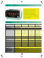
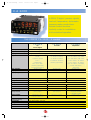
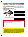
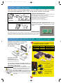
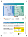
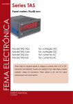
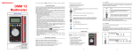
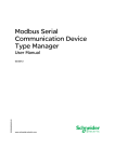
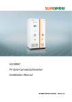
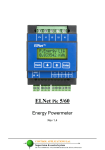
CA 2100/2200ang - 08/99
1/03/00 11:11
Page 2
Programmable
digital panel meters
s
ear ty
y
3 ran
war
Thought
C.A 2100
C.A 2200
out to the smallest of details...
for easy set up
and operation
■
■
■
■
■
■
■
■
■
■
Very simple programming
Holds minimum and maximum values in memory
Linearisation of the input signal on 11 segments (C.A 2200)
Serial link for remote processing of measurements
Instant installation, without tools
Screwless connectors easily plugged in
Accessories for wall mounting and on DIN rail
Supplied with 100 labels for different measurement units
Styled front panel with shaped touch keys
Front panel IP 65
CA 2100/2200ang - 08/99
1/03/00 11:12
Page 3
C.A 2100
6 DPM’s -999...9999 counts:
process signals, load cell,
temperature, voltage/current,
tachometer-frequencymeter
or meter-timer. Reduced depth
for easier installation in enclosures
and on equipment.
THE RANGE C.A 2100 : 6 models
C.A 2100-P
C.A 2100-C
C.A 2100-T
C.A 2100-E
U/l DC
Process Signals
Load Cells
Temperatures
AC / DC
Electrical Quantities
• voltage: 0...±10 V
• 0...±30 mVDC
• tc J: -50...800°C /
• voltage (5 calibres):
on 1 MΩ
on 100 MΩ
-58...1472°F
600 VAC or VDC maxi
• current: 0...±20 mA
• 0...±300 mVDC
• tc K: -50...1250°C /
• current (3 calibres):
Front panel
48 x 96 mm watertight IP 65
Depth from under flange
60 mm under flange
Display
4 digits, red LED 14 mm
Input
ADC Resolution
on < 9 Ω
on 1 MΩ
-58...2282°F
5 AAC or ADC maxi
(selection by programmation
(selection by wiring
• tc T: -200...400°C /
• shunt (3 calibres):
and wiring of the transducer)
of the transducer)
-328...752°F
100 mV max
• Pt 100: -100...800°C /
(selection by programmation
-148...1472°F
2 000 counts
and wiring input)
2 000 counts
2 000 counts
Display rate
3 times/second
4 times/second
3 times/second
3 times/second
Display range
-999...9999 ct
-999...9999 ct
depending on sensor
• DC: 0...9999 ct
• AC: -999...9999 ct
0.1% reading ±2 ct
0.1% reading ±3 ct
100 ppm/K
100 ppm/K
100 ppm/K
100 ppm/K
400 ms
400 ms
400 ms
5s
Accuracy
Temperature coefficient
Response time
MIN and MAX functions
OFFSET function
Probe excitation
2 000 counts
• tc: 0.2% reading ±0.5° • DC: 0.1% reading ±2 ct
• Pt 100: 0.1% reading ±0.2° • AC: 0.3% reading ±2 ct
yes
yes
yes
yes
yes, by keyboard
yes, by keyboard
yes, by program
no
30 mA at 10 or 24 VDC
30 mA at 5 or 10 VDC
no
no
Supply voltage
(specify when ordering)
dual voltage 115/230 V ±15% 50/60 Hz or dual voltage 24/48 V ±15% 50/60 Hz or 10.5...16 VDC or 21...32 VDC
Consumption
3 W without options
Weight (with connectors)
250 g without options; 320 g with options
Environmental conditions
use: 0...+50°C / RH < 95%
Material of the case
polycarbonate V0 in accordance with UL
storage : -25...+80°C
2
CA 2100/2200ang - 08/99
1/03/00 11:12
Page 10
The C.A 2100-P is particularly designed for the measurement of process signals output by “high level” sensors, with
direct readout in engineering units. Equipped as standard with a supply for sensors, it accepts the most widely used signals,
in the range ±10 V or ±20 mA. The display rule is programmable directly from the keyboard, without any calculation having to
be made. Very useful in certain applications such as weighing, the C.A 2100-P can acquire an OFFSET from the keyboard, by
simple acquisition of the measured value (tare).
The C.A 2100-C is specially designed for measuring loads (weights, forces, couples, pressures, etc.) by means of
low-level sensors such as strain gauge bridges. Here again, the display rule can be programmed directly on the keyboard.
To facilitate calibration for weighing applications, the C.A 2100 can acquire an OFFSET from the keyboard by simply capturing
the measurement.
The C.A 2100-T is designed for temperature measurement, from J, K, T, couples or Pt 100 Ω resistances. The measurements
can be displayed in degrees Celsius or Fahrenheit, with a resolution of a degree or a tenth of a degree. By programming, an
offset can be introduced to correct the possible shift of the temperature sensor.
And the
C.A 2100-E is specially designed for the measurement of AC or DC electric signals: voltages up to 600 V and
C.A 2100-F
C.A 2100-I
Frequencymeter
Tachometer
Meter
Timer
• magnetic sensor: Vin > 120 mVeff
• NAMUR sensor: Ion < 1 mADC / Ioff > 3 mADC / Rc = 1 kΩ
• TTL/24 V encoder or NPN/PNP sensor:
“1” > 1.6 VDC / “0” < 1.5 VDC
• dry contact: Vc = 5 V / Rc = 3.9 kΩ / Fc =100 Hz
(Fmin 0.1 Hz / Fmax 2 kHz)
• voltage: 10...650 VAC
-
10 000 counts
10 000 counts
< 1 times/second
< 1 times/second
• frequencymeter: 0...999.9 ct
• tachometer: 0...9999 ct
• meter: ±9999 ct
• timer: 99.99s to 9999h
0.01% reading ±1 ct
0.01% reading ±1 ct
50 ppm/°C
50 ppm/°C
0.1 to 9.9 s
-
yes
yes
yes, by keyboard
no
30 mA at 8 or 24 VDC
30 mA at 8 or 24 VDC
electric currents up to 5 A on direct input. Currents greater than
5 A will be measured by connection to a current transformer or a
shunt. Connected to a tachometric dynamo or to an alternator,
the C.A 2100-E allows the display of speeds directly in the
desired unit.
For voltage measurements, the instrument has four set ranges
and an automatic range, which selects the most suitable range
depending on the amplitude of the input voltage.
The C.A 2100-F is intended essentially for measuring
a rotation speed on the basis of the number of pulses per
revolution, a tangential or linear speed on the basis of a
frequency and the corresponding actual speed, a time of passage
on the basis of a frequency value and the actual time, a rate or a
frequency on the basis of an AC voltage or equivalent (passage
to 0).
The C.A 2100-I is dedicated to metering of external
electrical pulses and can be used to set up a meter, a countdown meter or a time-unit meter, such as a timer or time meter.
■ In addition to the display of the input variable, the panel meters
permanently record its minimum and maximum values.
■ Programming of the instrument is done by means of the three
keys on the front panel.
■ Measurements can be acquired by a PC via a serial link, then
processed by means of the DPMPROG software.
THE
OPTIONS OFFERED:
• 2 alarms on SPDT relays
• RS232 or RS485 serial link
• 4...20 mA analogue output for P, C, T and E models;
available at the end of 1999 for model F; not available for model I.
3
CA 2100/2200ang - 08/99
1/03/00 11:12
Page 5
C.A 2200
4 DPM’s "5-digits": process signals,
load cell, temperature, tachometerfrequencymeter-counter-timer.
Remote control functions.
Perfectly suited to installations
with centralised operation.
THE RANGE C.A 2200 : 4 models
C.A 2200-P
C.A 2200-C
C.A 2200-T
U/lDC
Process Signals
Load Cells
Temperatures
Front panel
48 x 96 mm watertight IP 65
Depth from under flange
120 mm under flange
Display
5 digits, red LED 14 mm + 1 digit, green LED, 8 mm
Input
• voltage: 0...±10 V
• 0...±15 mVDC on 100 MΩ
• tc J: -50...850°C / -58...1562°F
on 1 MΩ
• 0...±30 mVDC on 100 MΩ
• tc K: -50...1200°C / -58...2192°F
• current: 0...±20 mA
• 0...±60 mVDC on 100 MΩ
• tc T: -200...400°C / -328...752°F
on 15 Ω
• 0...±300 mVDC on 100 MΩ
• tc R: 0...1700°C / -32...3092°F
• potentiometer:
(selection by programmation)
• tc S: 0...1700°C / -32...3092°F
100 Ω min, 0...100%
• tc E: -50...1000°C / -58...1832°F
(selection by programmation
• Pt 100: -100...800°C /
ADC Resolution
±65 000 counts
±65 000 counts
-148...1472°F
±20 000 counts
Display rate
16 times/second
16 times/second
8 times/second
Display range
±32 000 counts
±32 000 counts
±9 999 counts
0.15 µV or 0.3 µA
0.01% reading ±2 ct
0.1°C or 1°C
50 ppm/°C
100 ppm/°C
50 ppm/°C
and wiring of the transducer)
Accuracy
Temperature coefficient
Response time
Linearisation
MIN and MAX functions
250, 425 or 775 ms depending on filtrage programmed
yes, on 11 segments
yes, on 11 segments
no
yes
yes
yes
OFFSET function
yes, by keyboard
yes, by keyboard
yes, by program
Remote control
(4 logical inputs)
26 preprogrammed functions
(see on page 6)
26 preprogrammed functions
(see on page 6)
Probe excitation
120 mA at 5 or 10 VDC
or 30 mA at 10 or 24 VDC
120 mA at 5 or 10 VDC
• hold display
• display MIN and MAX
• clear MIN and MAX
Pt 100 < 1 mADC
Supply voltage
dual voltage 115/230 V ±15% 50/60 Hz or dual voltage 24/48 V ±15% 50/60 Hz or 10...30 VDC
(specify when ordering)
Consumption
5 W without options, 10 W max
Weight (with connectors)
475 g without options; 850 g with options
Environmental conditions
use: 0...+50°C / RH < 95%
Material of the case
polycarbonate V0 in accordance with UL
storage : -25...+80°C
4
CA 2100/2200ang - 08/99
1/03/00 11:12
Page 6
The C.A 2200-P is particularly designed for the measurement, over 32,000 counts, of process signals issued by “high
level” sensors, with direct readout in engineering units. Equipped as standard with a supply for sensors (3 values), it accepts
the most widely used signals, in the range ±10 V or ±20 mA, and can also be connected to a potentiometric type transducer,
for the measurement of displacement, of length, etc.
The display rule is directly programmable on the keyboard and can be linearised on 11 segments for sensors with non-linear output.
Very useful in certain applications such as weighing, the C.A 2200-P can take an OFFSET from the keyboard, by simple acquisition
of the measured value (tare). Lastly, four logical inputs allow four remote controls, chosen among 26 preprogrammed functions.
The C.A 2200-C is specially designed for measuring loads (weights, forces, couples, pressures, etc.) over a range
of 32,000 counts by means of low-level sensors such as strain gauge bridges. It can also be connected to the terminals
of a DC intensity shunt. The display rule is directly programmable on the keyboard and can be linearised on 11 segments.
To facilitate calibration for weighing applications, the C.A 2200-C can acquire an
OFFSET from the keyboard by simply capturing the measurement. Lastly, four
logical inputs allow four remote controls, chosen among 26 preprogrammed
functions.
C.A 2200-D
Frequencymeter - Tachometer
Meter - Timer
• magnetic sensor: Vin > 120 mVeff
• NAMUR sensor:
Ion < 1 mADC / Ioff > 3 mADC / Rc = 1 kΩ
The C.A 2200-T is designed for temperatures measurements, from J, K, T, R,
S, E couples or Pt 100 Ω resistances. The measurements can be displayed in
degrees Celsius or Fahrenheit, with a resolution of a degree or a tenth of degree.
By programming, an offset can be introduced to correct the possible shift of the
temperature sensor. The display of the MIN and MAX values and their resetting to
zero can be controlled remotely by means of logical inputs.
The C.A 2200-D is mainly intended for exploitation of pulsed logical signals
for the following functions: meter with memory (batch counter, metering, countdown
or two-way metering), timer with memory, frequencymeter and tachometer (frequency,
rotation speed, linear speed, rate, time, etc.). The display of the MIN and MAX values
and their resetting to zero can be controlled remotely by means of logical inputs.
• TTL/24 V encoder or NPN/PNP
sensor: “1” > 1.6 VDC / “0” < 1.5 VDC
• dry contact: Vc = 5 V / Rc = 3,9 kΩ
• voltage: 10...650VAC
(Fmin 0.05 Hz / Fmax 20 kHz)
4 times/second
• metter: ±99999 counts
• timer: 0.00 s to 9999.9 h
• frequencymeter: 0...25 000 counts
• tachometer: 0...99999 counts
0.01% reading ±1 ct
50 ppm/°C
■ On both instruments, two digital filters can be used to stabilise the display of
measurements as a function of the process conditions.
■ In addition to the display of the input variable, the DPM permanently record the
minimum and maximum values.
■ Display of the measurement can be inhibited remotely by closing a contact and the
MIN and MAX values can be displayed and cleared remotely.
■ On the C.A 2200-P and C.A 2200-C, the OFFSET can also be entered and cleared
remotely. And the remote control functions can be modified as the user requires,
with a total of 26 preprogrammed functions available in these instruments.
■ Again on the C.A 2200-P and C.A 2200-C, the display can be set to flash when an
alarm threshold is exceeded.
no
■ Programming of the instruments is done by means of the five keys on the front
yes
panel, or remotely, on a PC, by means of the DPMPROG software and a serial link.
yes, by keyboard
• hold display
• display MIN, MAX and RESET
• clear MIN, MAX and RESET
30 mA at 8 or 24 VDC
THE
•
•
•
•
OPTIONS OFFERED:
2 or 4 alarms on relays or opto-couplers
analogue output
BCD output
RS232 or RS485 serial link
5
CA 2100/2200ang - 08/99
1/03/00 11:12
Page 7
Control functions
These logical inputs allow the HOLD display function as well as
display and resetting of the MIN and MAX memories to be
controlled remotely by closing a contact.
The C.A 2200 panel meters have four logical inputs
located on an removable connector on the back of the
instrument.
RESET (function 7)
HOLD (function 9)
Common
OFFSET (function 1)
MAX / MIN (function 6)
On the C.A 2200-P and C.A 2200-C, 22 other functions can be
assigned to the four logical inputs by programming. Each of
them is then used to control a separate function chosen among
those listed below.
POSSIBLE FUNCTIONS WITH THE C.A 2200-P & C.A 2200-C LOGICAL INPUTS
Control
None
Pulse
Pulse
Pulse
Pulse
Pulse
Pulse
Maintained plus (1)
or (6)
Maintained
Maintained
Maintained
Maintained
Maintained
Maintained
Maintained
Maintained
Maintained
Pulse
Pulse
Pulse
Pulse
Pulse
Pulse
Pulse
Maintained
Pulse
Maintained
Maintained
Small details that make all the difference.
These functions provide extra performance to meet the current industrial requirements. With DPM’s, it is now possible to:
• Generate new functions with or without interfacing with other systems to limit the complexity of the production and
quality testing equipment
• Place these functions under the control of operations managed by systems which are not part of the measurement chain
• Recover the data for testing in a simple way.
For example:
Function 10. This command, which displays the actual value of the input signal, can be used to check that the sensor is operating correctly.
Functions 13 to 16. These commands index the analogue output to derived values instead of to the measurement value.
Functions 17 to 23. These commands send a memorised value via the serial output to a printer or other peripheral device.
Function 24. When the panel meter is not equipped with an "alarms" board, this command can be used to simulate
activation of the alarm thresholds. The frontal LEDs will then indicate the fictitious status of the alarms.
Function 25. When an alarm threshold declared with the latch function is active, it must be possible to acknowledge the
alarm once the fault has been corrected. This command cancels the latch on latched alarms.
Function 26. This command can be used to record or print the measurement signal directly after its analogue-digital conversion, i.e.
without any filtering or scale factor. This means that you can check all the dynamic faults on the system.
6
* Factory configuration
Nº
Function
Description
display and memory functions
0
None
When assigned to an input, it deactivates it.
When assigned to all the inputs, it resets them to the factory configuration (functions 1, 6, 7 and 9).
1
OFFSET*
Records the displayed value as the OFFSET and resets the display to zero.
2
RESET OFFSET
Adds the OFFSET to the displayed value and deletes the value in the memory.
3
MAX
Displays the MAX value. Or other pulse, return to reading.
4
MIN
Displays the MIN value. Or other pulse, return to reading.
5
RESET MAX/MIN
Reinitialises the MAX or MIN (depending on which one is displayed on the main display).
6
MAX/MIN*
1st pulse: MAX display, 2nd pulse: MIN, 3rd pulse MEASUREMENT.
7
RESET*
Combined with (1), deletes the OFFSET value.
Combined with (6), resets MAX or MIN.
8
HOLD1
Blocks the display while all the outputs remain active.
9
HOLD2*
Blocks the display, the BCD output and the analogue output.
functions associated with the measurement variable
10
INPUT
Displays the real value of the input voltage, in mV (intermittent).
11
GROSS
Displays measured value + OFFSET value = gross value.
12
OFFSET
Displays the OFFSET value in the memory.
functions associated with the analogue output
13
GROSS ANALOGUE
The analogue output is the image of the gross value (display value + OFFSET).
14
ZERO ANALOGUE
Forces the analogue output to zero (i.e. 0V or 4mA).
15
MAX ANALOGUE
The analogue output follows the evolution of the MAX value.
16
MIN ANALOGUE
The analogue output follows the evolution of the MIN value.
functions for use of a printer on the RS output
17
PRINT NET
Prints the net value.
18
PRINT GROSS
Prints the gross value.
19
PRINT OFFSET
Prints the OFFSET value.
20
PRINT SET1
Prints the value and status of threshold 1.
21
PRINT SET2
Prints the value and status of threshold 2.
22
PRINT SET3
Prints the value and status of threshold 3.
23
PRINT SET4
Prints the value and status of threshold 4.
functions associated with the alarms
FICTITIOUS THRESHOLDS Used exclusively for instruments which do not have any "alarms" option installed.
24
25
ALARMS RESET
Deactivates the latched relays on instruments programmed with "latch" thresholds.
special functions
26
RS ROUNDED
Transmission to the serial output of the display value without rounding or filtering.
27
BCD ROUNDED
Transmission to the BCD output of the display value without rounding or filtering.
CA 2100/2200ang - 08/99
1/03/00 11:12
Page 8
THE OPTIONS : for the most varied of applications
When ordered with the panel meter, the options will be installed by our services.
They are also easily installed by the user at a later date.
On the C.A 2200, it is possible to simultaneously install an
alarm card, an analogue output card and a communication
card. On the other hand, the BCD card rules out the installation
of other options.
Card 2 Alarms on relays
for C.A 2100 or 2200
Both channels are independently configurable and can be set
as high or low alarm. With the C.A 2200, the 2nd alarm can be
set as following the 1st. On C.A 2200-P and C.A 2200-C
models, the alarms can be assigned to the measurement
value, to the MIN or MAX values, or even to the gross value,
and can be latched, thus they act when the overvalue has
disappear. The reset of the latch alarms is controlled by the
logical inputs.
The alarm outputs are made on SPDT relays, with an adjustable
delay or hysteresis.
As with the C.A 2100, they simultaneously accept the cards
“2 Alarms on relays” and “RS232/485 Communication” or
“Analogue Output MAN” card.
The installation of the option cards
is very easy. Here, the C.A 2100.
Outputs
Max voltage
Max current
2 relays “change-over contact”
250 VAC or 125 V DC
8 A at 250 VAC or 8 A at 24 VDC
Card 4 Alarms on relays
for C.A 2200
In the same way, allows programming of four independent
alarms, or two independent alarms with two following alarms.
Outputs
Max voltage
Max current
4 relays “make contact”
250 VAC or 50 VAC
500 mA at 125 VAC or 1 A at 30 VAC
Card 4 Alarms on NPN transistors
No calibration is necessary after the installation of the option
cards: the programme recognises them automatically and runs
the instructions necessary for setting their parameters.
for C.A 2200
It is identical to the preceding one, with the exception of the
outputs which are done by opto-couplers.
Outputs
Max voltage
Max current
All the outputs of the option cards are insulated from the
input signal by opto-couplers.
4 opto-couplers NPN
50 VDC
50 mA at 50 VDC
Programming makes the alarms completely configurable:
• HI alarm or LO alarm. In HI mode, the output is on when the measurement reaches or overshoots the value of the threshold.
In LO mode, the output is on when the measurement reaches or remains below the value of the threshold.
• Timed alarm. All the alarm channels can be delayed by the timer, from 0.1 to 999.9 seconds. The timer acts on both sides of
the threshold, i.e. in whatever direction it is crossed.
• Alarm with asymmetrical hysteresis. The hysteresis is programmed directly in display units, between 0.001 and 9999. For a high
alarm, the threshold value is added. It is deducted for a low alarm. In this way, the return to rest of the alarm outputs is delayed.
• Alarm with symmetrical hysteresis (on C.A 2200). The programmed hysteresis is added to each side of the threshold,
defining a band in which the output is on (high alarm) or off (low alarm).
• Following alarm (on C.A 2200). The second and the fourth alarm (for the 4 ALARMS cards) can be defined as following alarms
for the first and third alarm respectively. A following alarm will react depending on the threshold of the alarm it is slaved to, with
an offset defined by programming. The gap can take any positive or negative value.
• LATCH alarm. This function can be used to keep an alarm active or inactive even if the value falls below the programmed
threshold. A logical input will be assigned to cancel this latch function.
A small detail that makes all the difference.
On the C.A 2200, the second alarm, whatever the card, can be defined as following alarm with automatic correction of the
residual measurement. In numerous cases, particularly in weighing and dosing operations, the mechanical systems and
the architecture of the installation result in it being impossible to immediately stop the operation as soon as the setpoint is reached.
For example, the “tailing-off” effect occurs in filling systems in which, when a programmed quantity is reached, an alarm causes
blocking of the conduit. The time taken to close the protective cover and the quantity flowing during this time lapse give rise to a
surplus of material in relation to the exact quantity required. The result is a real measurement greater than the setpoint (measurement
residual). The “auto follow” function (AUTOTRAC) is specially designed to correct this measurement residual. It determines the
excess quantity in relation to the programmed threshold and subtracts from the measurement, to switch on the alarm output with
a minimum gap in relation to the threshold. Thus the surplus or insufficient quantity is permanently corrected.
7
CA 2100/2200ang - 08/99
1/03/00 11:12
Card Analogue Output
Page 9
for C.A 2200
Card RS232 Communication
It outputs a DC linear signal, proportional to a display range
defined by programming. The output then retransmits the display
variations between the two programmed points, giving rise to a
“zoom” effect around a given value. The analogue output can
also vary inversely to the display, if you allocate to the higher
value of the analogue output (OUT-HI) the low value of the display
range, and to the lower value of the output (OUT-LO) the higher
value of the display range. The response time of the analogue
output (60 ms) can also be increased to limit the transmission
of undesirable disturbance.
Output signal
Accuracy
Temperature coeff.
Max load
0…10 V
0.1% ± 1 digit
0.2 mV per K
≥ 500 Ω
Card MAN Analogue Output
This option allows connection of a C.A 2200 to a master instrument
(PC, PLC,...) to programme the instrument and exploit the
measurements, for example using the DPMPROG software
supplied with the card.
Type of link
Protocol
Rate
Output connector
Card BCD Output
for C.A 2200
It allows connection in a network of up to 31 panel meters to a
master, to programme the instruments and process their
measurements. The DPMPROG software is supplied with the card.
Type of link
Protocol
Rate
Output connector
for C.A 2100
RS485
ISO 1745 or C.A, half duplex
1200, 2400, 4800, 9600 or 19200 bauds
RJ11-6, with double adapter (in + out)
Card RS232/485 Communication
4…20 mA
0.2% ± 1 digit
2 µA per K
500 Ω
for C.A 2100
This option, specific to C.A 2100 panel meters, allows establishment
of an RS232 or RS485 digital link with a master instrument.
Selection is done by programming. The RS 232 link is used to
establish a monopoint link (1 panel meter), and the RS 485 is
used to create a network of instruments (up to 31). The DPMPROG
software, supplied with the card, allows measurements to be
stored and displayed on a PC.
for C.A 2200
This option transmits the measurements in code form in binary
decimal (8-4-2-1) at the display speed. The signals are compatible
TTL and 24 V logic.
Output transistors
Logic
Output connector
RS232C
ISO 1745 or C.A, half duplex
1200, 2400, 4800, 9600 or 19200 bauds
RJ9-4
Card RS485 Communication
4…20 mA
0.1% ± 1 digit
0.5 µA per K
≤ 800 Ω
(For P, C, T and E models; available at the end of 99 for model F;
not available for model I).
Output signal
Accuracy
Temperature coeff.
Max load
for C.A 2200
Type of link
Protocol
Rate
Output connector
NPN ; 40 V maxi, 100 mA maxi
positive or negative
SUD-B 37 pins
RS232C
RS485
ISO 1745 or C.A, half duplex
1200, 2400, 4800 or 9600 bauds
RJ9-4
RJ11-6, with double adapter
(in + out)
PROGRAMMING : simplicity is the key
Designed to make the job easier for you: only the instructions specific to your
application appear. You can’t go wrong!
The C.A 2200 panel meters can also be programmed
remotely, on a PC equipped with the DPMPROG software
supplied with digital link cards.
Maximum of five stages, depending on the options installe :
• input signal
• display rule
• alarms (if option used)
• analogue output (on C.A 2200, if option used)
• serial link (if option used)
A small detail that makes the difference.
To further simplify the display rule, rather than
introducing by the keyboard the input values
corresponding to the start and end of the scale, they can
be acquired by taking into account the signal present at the
input.
The programme has been designed to make setting the
parameters simpler, and as clear as possible : thus, for
example, the instrument automatically recognises the option
cards installed and calls up the corresponding programme
stages. Similarly, the metrological shifts of each card are
automatically compensated.
Display
On all the instruments, access to programming can be
prohibited. On the C.A 2200, it can in addition be limited to
certain instructions.
P2
P1
Measurement
8
CA 2100/2200ang - 08/99
1/03/00 11:12
Page 4
DIGITAL LINKS : the choice
With the serial communication options, the C.A 2100 and C.A 2200 are suitable
for supervised operation by PC, PLC, or any other "master" instrument.
Master
RS
RS 23
48 2
5
Port Com.
235
RS 485 link
The RS232C and RS485 links allow :
• reading of the measured values and memorised values in the
panel meter (MAX, MIN, OFFSET*, thresholds).
• the transmission of orders (requests, zero reset of the MAX,
MIN, OFFSET* values, setting the OFFSET*).
• modification of the alarm thresholds
Cables P01.3194.04
Converter P01.3707.20
-195,2
43,23
*OFFSET: on C.A 2100-P and C.A 2200 models P and C.
From 1 to 31 C.A 2100 or C.A 2200 panel meters in a network.
Transmission takes place in half-duplex mode, using the
ISO 1745 protocol or the simplified C.A protocol, at a speed
between 1200 and 9600 bauds, or 19800 bauds for the C.A 2200
models.
RS232C link
Port Com.
Cable P01.3194.03
227,5
Maître
C.A 2100 or C.A 2200
DPMPROG software
This software, which runs under MS-DOS, can be used to read the measurements
made by the different panel meters and to program remotely one or more C.A 2200
connected in a network. The standard delivery includes the serial link option boards.
DIMENSIONS AND INSTALLATION : simplicity once again
Whether mounting or connecting
the panel meters, we make
your work as simple
as possible.
45 mm
Watertight
joint
Mounting
Wall / in enclosure
On table
On ceiling
Sym / asym DIN Rail
92
48 mm
C.A
Small details that make the difference.
Two ingenious accessories are available, for surface
mounting of instruments, or on DIN rail.
Rear mounting
yes
yes
Multiposition mounting
yes, can be angled ±14°
yes, can be angled ±14°
yes, can be angled ±14°
yes, can be angled ±14°
Mounting
clips
21
00
96 mm
60 mm
14
Instruments are mounted
instantaneously, without
tools, by means of two flexible
straps that clip on to the case.
C.A
22
00
120 mm
96 mm
14
The connection of instruments is by rapid connectors, with
spring clips. And the connectors are removable, to make panel
meters easier to mount or remove.
Cross-section of cable: 0,08 mm2 ≤ Ø ≤ 2,5 mm2.
The connectors are equipped with removable
Lever supplied with
the connector.
reducers, to improve the reliability of the connection
of wires of cross-section less than 0.5 mm2.
No screws to tighten, means good grip over
time, and the possibility of installing these panel
meters without even a screwdriver. But, for those
who prefer, screw connectors are available as
accessories.
9
Each instrument is supplied with 4 sheets
of labels- adhesive unit symbols.
This makes a total of 97
A
predefined measurement
~
units and 3 blank labels
for customisation.
bar
Once they have been
stuck on, the label
blends harmoniously
with the keys on the
front panel.
CA 2100/2200ang - 08/99
1/03/00 11:11
Page 1
TO ORDER
Use the code tables below to order the panel meters with their options installed.
For the accessories, sold separately, use the references given further down the page.
• • • • •
Process
Temperature
Load cell
Tachometer/Timer
P
T
C
D
Power supply
Alarms
115/230 VAC
24/48 VAC
10...30 VDC
Type
1
3
5
no
AL 2 RELAYS
AL 4 RELAYS
AL 4 NPN
Analogue output
Digital communication
User manual
•
X
1
2
3
no
X
ANALOG OUTPUT 1
no
COM. RS232
COM. RS485
BCD OUTPUT*
french (by default)
english
german
X
2
3
4
F
E
D
DPM C.A 2100-
• • • • •
Process
Temperature
Load cell
Electrical
Tachometer/Frequencymeter
Meter/Timer
P
T
C
E
F
I
Power supply
115/230 VAC
24 VDC
24/48 VAC
12 VDC
Alarms
no
AL 2 RELAYS
•
1
2
3
4
X
1
Analogue output **
no
4/20 mA
X
2
Digital communication
no
COM. RS232/485
User manual
french (by default)
english
german
X
1
F
E
D
** For P, C, T and E models; available at the end of 1999 for model F; not available for model I
* This choice excludes other options
01 53 42 12 30
Type
DPM C.A 2200-
Option cards
•
•
•
•
•
•
•
MULTIPOSITION MOUNTING with 2 DIN rail adapters
REAR MOUNTING with 2 DIN rail adapters
CONNECTOR + CABLE 1m RS232
CONNECTOR + CABLE 1m RS485
SET OF 4 SCREW CONNECTORS CA2100
SET OF 6 SCREW CONNECTORS CA2200
CONVERTER RS232-25F/RS485-screw
ref. P01.3194.01
ref. P01.3194.02
ref. P01.3194.03
ref. P01.3194.04
ref. P01.3194.05
ref. P01.3194.06
ref. P01.3707.20
Card CA2XXX AL 2 RELAYS
Card CA2200 AL 4 RELAYS
Card CA2200 AL 4 NPN
Card CA2200 ANALOG OUTPUT
Card CA2200 BCD OUTPUT
Card CA2100 COM. RS232/485
Card CA2200 COM. RS232
Card CA2200 COM. RS485
Card CA2100 ANALOG OUTPUT
ref. P01.3193.01
ref. P01.3193.03
ref. P01.3193.04
ref. P01.3193.05
ref. P01.3193.08
ref. P01.3193.02
ref. P01.3193.06
ref. P01.3193.07
Mid-99
SERVICE : included
As important as the technical performance of the product, the services offered
must also be taken into account when the purchasing decision is taken.
The C.A 2100 and C.A 2200 panel meters are guaranteed for
36 months against any manufacturing fault. Our service is
based on a worldwide network, with a strength of 7 subsidiaries
in Europe and U.S.A., 70 agents and more than 2000 distributors
on the five continents.
The options ordered with the instruments are assembled in
our factories, at no extra charge. And for a modest price,
we offer to do the programming of your instruments, to your
specifications (ask us for the form designed for this purpose).
FRANCE
1-9, rue d’Arcueil - BP 675
92542 MONTROUGE Cedex
Tel.: (33) 01 47 46 78 85
Fax: (33) 01 47 35 01 33
E-mail : [email protected]
Lastly, Chauvin Arnoux offers you an immense choice of
products in its catalogue to build complete measurement
systems around your panel meters (sensors, current transformers,
shunts, recorders, measurement relays,...).
A small detail that makes the difference.
Each panel meter is supplied with a very detailed user
manual, with numerous illustrations.
UNITED KINGDOM
Waldeck House - Waldeck Road
Maidenhead SL6 8BR
Tel.: 01628 788 888
Fax: 01628 628 099
E-mail : [email protected]
h t t p : / / w w w . c h a u v i n - a r n o u x . c o m
Also available
in French
and German.
CHAUVIN
ARNOUX
906.111.627 - Ed. 2 - 08/99 - Non contractual document. Confirm specifications before ordering.
•
•
•
•
•
•
•
•
•
Accessories
Création & Réalisation
Use the references below to order the additional option cards
(additions or replacements)