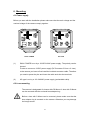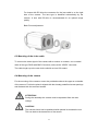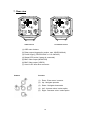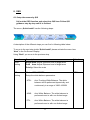
1
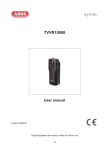
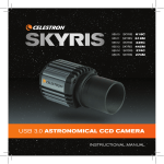
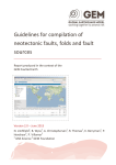
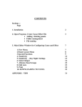
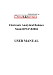
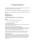
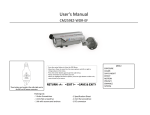
WDR Day/Night 650 TVL Backfocus Camera Version 2010-A Oringinal English user Manual. Keep for future use 1 Introduction Dear Customer, Thank you for purchasing this product. This product meets the requirements of the applicable European and national guidelines. The corresponding declarations and documents can be obtained from the manufacturer. To maintain this condition and to ensure risk-free operation, you as the user must observe these operation instructions! Before initial start-up, read through the complete operating instructions observing operating and safety instructions. All company and product names mentioned in this document are registered trademarks. All rights reserved. If you have any questions, please contact your installer or your local dealer! Disclaimer This user manual was prepared with greatest care. If you should notice omissions or inaccuracies, please inform us about these on the back of this manual given address. product or user manual without a previous announcement. The company is not liable or responsible for direct and indirect subsequent damages which are caused in connection with the equipment, the performance and the use of this product. No guarantee for the content of this document is taken. 2 Important safety instructions The warranty will expire for damage due to non-compliance with these operating instructions. We shall not be liable for any consequential loss! We do not accept liability for damage to property or personal injury caused by incorrect handling or non-compliance with the safety-instructions. In such cases the warranty will expire. Dear customer, The following safety instructions are intended not only for the protection of your health, but also for the protection of the device. Please read through the following points carefully: • There are no parts on the inside of the product which need to be serviced. Apart from this, the license (CE) and the guarantee/warranty will lapse if you open/take the product apart. • The product will be damaged even it falls from a low height. Avoid using the device under the following unfavorable ambient conditions: • wetness or excessive air humidity • extreme cold or heat • direct sunlight • dust or combustible gases, vapors or solvents • strong vibration • strong magnetic fields, such as those found in the vicinity of machinery or loudspeakers • the camera should not positioned with opened iris towards the sun this can lead to destruction of the sensor. • the camera may not be installed on unstable surfaces General safety instructions: • Do not leave packaging material lying around carelessly. Plastic/ foil/bags and polystyrene parts etc. could become dangerous toys for children. • For safety reasons don’t give the camera into child hands due to them being able to swallow small parts. • Please do not insert objects through the openings into the device. 3 • Use only accessories which are specified by the manufacturer. Please do not connect incompatible parts to the device. • Please pay attention to the safety instructions and user manuals of the other connected devices. • Check the device for damages before installation. If this should be the case please do not use it. • Please adhere to the operational voltage limitations listed in the technical data. High voltage could destroy the device and pose a health hazard (electric shock). During the installation into an existing video surveillance system make sure that all devices are disconnected from the low and supply voltage circuit. If in doubt allow a professional electrician to mount, install and wire-up your device. Improper or make-do electrical connection to the mains does only represent at threat to you but also to other persons. Wire-up the entire system making sure that the mains and low voltage circuit remain separated and cannot come into contact with each other in normal use or due to any malfunctioning. 4 Table of contents 1. Intended use.............................................................................................................06 2. Explanation of symbols...........................................................................................06 3. Scope of delivery .....................................................................................................07 4. Features and functions ...........................................................................................07 5. Description of device ..............................................................................................07 5.1 Overview – article numbers ..............................................................................07 5.2 Unpacking ........................................................................................................07 6. Mounting...................................................................................................................08 6.1 Power supply....................................................................................................08 6.2 Lens mounting..................................................................................................08 6.3 Mounting of the video cable..............................................................................09 6.4 Mounting of the camera....................................................................................09 7. Rear view ..................................................................................................................10 8. OSD...........................................................................................................................11 9. Servicing and cleaning............................................................................................14 9.1 Function test.....................................................................................................14 9.2 Cleaning ...........................................................................................................14 10. Disposal....................................................................................................................14 11. Technical data..........................................................................................................15 5 1. Intended use The WDR Day/Night 540 TVL Standard Camera is equipped with a high quality image sensor. It is used for video surveillance in internal areas in connection with a recorder or monitor. You can find a detailed description of functions in section “4. Features and functions”. The product should not become damp or wet. The camera is only for use in dry indoor areas. Any other use than that described above can lead to damage to the product and in addition involve other risks. This does not include operation for other applications and would in case of doing so the guarantee and any related liability will lapse. This is also the case if any unauthorized changes or additions have been made to the product. Please read through the entire manual carefully before putting this product into operation. This operating manual contains guidelines that are important for correct mounting and operating. 2. Explanation of symbols A flash in the triangle is used if there is danger for the health, e.g. by an electric shock. An exclamation mark in the triangle points to an important note in this user manual which must be minded. This symbol can be found when you are to be given tips and information on operation. 6 3. Scope of delivery • WDR Day/Night 650 TVL Standard Camera • C-Mount lens adapter ring • Mounting bracket and screws for camera bracket • User manual 4. Features and functions • Sony Effio-Pro newest DSP • Backlight compensation with high dynamic range (WDR) • Day/Night camera with removable IR cut filter (ICR) • 2D + 3D DNR Support. • On-Screen-Menu for easy camera setup (OSD) • Dual-Video output (2 x BNC) 5. Description of device 5.1 Overview – article numbers Article Number Resolution Day/Night (removable IR cut-filter) Operating voltage DUAL POWER AC TYPE 650 650 √ √ 12VDC/24VAC 110-240VAC 5.2 Unpacking While you are unpacking the device please handle it with utmost care. If you notice any damage of the original packaging, please check at first the device. If the device shows damages, please contact your local dealer. 7 6. Mounting 6.1 Power supply Before you start with the installation please make sure that the main voltage and the nominal voltage of the camera comply together. MONITOR MONITOR POWER POWER EXT EXT 12VDC/24VAC VIDEO DUAL POWER (1) VIDEO 110-240VAC AC TYPE DUAL POWER is run by a 12VDC/24VAC power supply. The polarity can be ignored. In order to connect a 12VDC power supply (DC Connector 5.5mm x 2.1mm) to the camera you have to first install the included connector cable. Therefore you need to press the pins and insert the cable ends into the terminals. (2) AC type is run by a 110~240VAC power supply (preinstalled cable). 6.2 Lens mounting The camera is designated for lenses with CS-Mount. A lens with C-Mount can be mounted with the enclosed lens adapter ring. Before a lens with C-Mount can be mounted, please make sure that the lens adapter ring is mounted on the camera. Otherwise you may damage the image sensor. 8 For lenses with DC-drive the connector for the lens cable is on the right side of the camera. The lens type is identified automatically by the camera. A lens with DC-drive is recommended for an optimal image quality. Back-Focus adjustment: 6.3 Mounting of the video cable To connect the video signal of the camera with a monitor or recorder, use a coaxial cable of the type RG59 with BNC-Connector (male) at the “VIDEO” connector. The cable length up to the next device should not rise 100 meters. 6.4 Mounting of the camera For the mounting of the camera, mount the provided socket at the upper or underside of the camera. For this the plate is aligned with the already predefined screw openings and fastened with the enclosed screws. ATTENTION! During the assembly the camera must be separated from the main voltage. CAUTION! The camera should not be positioned with opened iris towards the sun. This can lead to the destruction of the sensor. 9 7. Rear view 6 1 7 MONITOR 4 POWER EXT 12VDC/24VAC 2 MONITOR 7 POWER 5 3 6 1 4 5 3 EXT VIDEO 110-240VAC 12VDC Version 2 VIDEO 110~240VAC Version (1) OSD menu buttons (2) Relay output (triggered by motion, max. 60VDC/400mA) (3) Power Supply (12VDC/24VAC or 110~240VAC) (4) Status LED (active if power is connected) (5) BNC Video output (MONITOR) (6) BNC Video output (VIDEO) (7) Auto iris DC lens driver connector Buttons Function 2 (1) Enter : Enter menu / execute (2) Up : Navigate upwards 4 5 1 (3) Down : Navigate downwards (4) Left : Increase value / select option (5) Right : Decrease value / select option 3 10 8. OSD 8.1 Setup the camera by QIS Call out the OSD function and select into QIS item. Follow QIS guidance step by step until it is finished The menu „Quick Install“ has the following steps: A description of the different steps you can find in following table below. To move to the next step inside “Quick Install” please activate the menu item “Next” in the On-Screen-Display. Using “Back” you move to the previous step. Function Description Default WDR Setting Bright Area: Adjust Exposure level of bright area Dark Area: Adjust Exposure level of bright area Priority: Select the main WB Setting Mode: ATW/AWB/PTL Setup the white balance parameters ATW : Auto Tracking White Balance. The white balance will be performed dynamically and continuously in a range of 1800~10500K AWB : Auto White Balance. The white balance is performed once in with non limited range. PTL : Auto White Balance. The white balance is performed once in with non limited range 11 ATW DNR Setting DNR Mode: 2D DNR / 3D DNR /2D+3D DNR You can select the Digital Noise Reduce Mode- 2D+3D 2D DNR : 2D DNR is for still object to keep the resolution and low light noise 3D DNR : More details in darker image areas High dynamic range Useful for high contrast indoor scenarios Focus Setting In this mode is optimize setting to easy set in right focus - 8.2 ADVANCE MENU ADVANCE MENU has functions that are less used. This is for application purpose ADVANCE MENU Exposure W.B Enhance D/N Detect Miscellaneous Restore Default Return End z Exposure: WD: The user can set the shutter level of Bright/Dark area. (The Auto iris level in WD mode is automatic adjusted by DSP itself) DC: this mode is running in Non-WD , adjust the DC lens driver level ME :This mode is running in Non-WD , adjust the manual shutter and Gain AES: it sets the upper/lower auto electronic shutter limit. 12 z W.B: AWB: in this mode the white balance range is unlimited ATW: in this mode the tracking white balance is within 1800-10500K PTL: in this mode color temp. is locked z Enhance: AGC: The camera can adjust the AGC up to 62.8 dB Gamma: The camera has 6 gamma curve to be selected Aperture : This is for sharpness adjustment Slow shutter: Max. at 128X D/N: This item can set the detail for D/N switching Auto Mode: the D/N switch is basee on AGC or CDS level and also can adjust delay time / level, color setting. Fixed mode: Day / Night mode only. z z z Detect: Face : the camera DSP can detect max 4 human faces at the same time Motion Detection: this item can set Motion detection ON/OFF. Max. 128 blocks can be selected Miscellaneous : This item is for additional function adjustments DNR: This camera has 2D/3D Digital Noise Reduction, and camera can work at 2D , 3D or 2D+3D mode Mirror: The camera has Vertical and Horizontal image reverse Mask: The camera has max. 8 areas to be set with color and position Camera ID: Each camera can be set with its own ID Winker: This is an OSD blinking in upper right corner of image, this function is to indicate the camera is working in condition that has no object movements E-Zoom: The camera has max 5X digital Zoom. Restore Default: Restore the default by this item z 13 9. Servicing and cleaning 9.1 Function test Check the technical safety of the product such as damage to the housing at regular intervals. When it can be assumed that the safe operation is no longer possible, the product must be put out of service and precautions taken o ensure that it is not used unintentionally. It must be assumed that safe operation is not longer possible if • the device shows visible signs of damage • the device no longer operates and • has been stored for longer periods under unfavorable conditions or • has been subjected to considerable stress in transit. Please note: The product is absolutely maintenance-free for you. There are no components on the inside of the product to be checked or services by you, never open it. 9.2 Cleaning Clean the product with a clean, soft cloth. To remove severe contamination, the cloth can be dampened with luke-warm water. Make sure that no liquids can enter the equipment as the device can be destroyed. Never use chemical detergents as they could attack the surface of the device. 10. Disposal Products which are labeled with this pictogram may not be disposed by the domestic rubbish. Please dispose the product in accordance with the prevailing legal regulations at the end of its life time. Please consult your dealer or dispose the product over the municipal gathering point for electric scarp. 14 11. Technical data Article no. XCAA201A Image sensor XCAA201A XCAA201B 1/3” Interline Transfer SuperHAD II dual scan CCD Signal system Picture element XCAA201B PAL NTSC 976 (H) x 582 (V) 976 (H) x 494 (V) Horizontal resolution 650 TVL Synchronization Internal Scanning 2:1 Interlace Min. illumination (day) 0.1 Lux @ F1.0, 30 IRE 0.01 Lux @ F1.0, 30 IRE (B/W Modus) Min. illumination (night) 0 Lux @ F1.0, 30 IRE (IR An) Wide dynamic range 54dB Sense up 4x factory default (2x - 256x customization) S/N ratio better than 50dB AGC 62.8dB (analog + Digital) White balance control ATW (1800°K - 10500°K) / AWB DNR 2D / 3D / 2D+3D DNR Gamma 8 level adjustment OSD control OSD control (QIS / Advance) BLC ON / OFF Masking 16 Areas Digital zoom x1 ~ x5 Mirroring Horizontal and Vertical Automatic day/night Removable IR cut filter (ICR), Color / B/W switching Iris level adjustment Yes Lens CS/C-Mount, manual or DC controlled Intelligent MD/FD ON / OFF Video output composite: 1.0 Vp-p at 75Ω load Operating temperature -10°C ~ +50°C Humidity Power supply Power consumption 0~85%, not condensing 12 VDC / 24 VAC 110~240 VAC 12 VDC / 24 VAC 110~240 VAC 4.4W 4.5W 4.4W 4.5W Dimensions (WxHxD) 65 x 72 x 119mm Weight 420g 15 64.55mm 109.13mm H K 64.3mm 72.05mm POWER C I A EXT 12VDC/24VAC 118.6mm 16 VIDEO