1
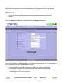
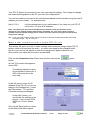
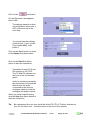
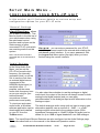
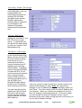
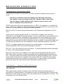
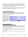
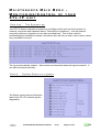
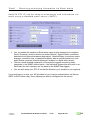
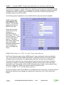
BROADCAST Audio TX STL-IP IP Network Audio Device for Live audio over IP Networks and the Internet User Manual & Reference Guide Firmware revision 1.2b, September 2005 WARNING: This device MUST be earthed. A standard 3-pin IEC power connector should be used for mains connection, including an earth connection. This earth is connected to the chassis metalwork. A 3amp fuse should be fitted in the mains plug or, alternatively, suitable protection should be installed in the mains circuit supplying the unit. The unit should not be opened or serviced except by appropriately qualified personnel. To reduce the risk of electric shock: - Do not insert objects into the chassis ventilation holes or any other device apertures. - Do not expose the unit to rain or moisture. The ventilation holes on the sides of the chassis and the two fan outlets on the rear must allow for free air-flow and must not be obscured. Product Manual & Reference Guide v1.2b Page 2 of 37 CONTENTS Page 5 Introduction Description of controls, indicators and connectors 6 Front Panel Rear Panel 5 5 How to use the Web Browser based user interface 7 Menus & Settings Built-in Help & Manual 8 8 Quick Start Guide 9 Setup the STL-IP system on your network Make a test connection with a single STL-IP unit 9 11 Connections Main Menu - setting up audio connections 13 Guide to Connection and Audio types ‘Status’ - view and configure audio connections Transmit Settings (TX-0 to TX-5) Network bitrates Receive Settings (RX) ‘Start’ ‘Stop’ 13 16 16 18 18 18 18 Setup Main Menu - configuring your STL-IP unit 19 ‘General’ Settings ‘Audio’ Settings ‘Ancillary Data’ Settings ‘Clock’ Settings ‘Network’ Settings 19 19 20 20 20 Advanced operation 21 Forward Error Correction (FEC) Jitter Buffer - Network Safety Buffering Silence detectors - input/output Transmitting and Receiving ancillary RS-232 data alongside audio GPIO - end to end TTL signals alongside your audio Status outputs available on the GPIO connector Proxies, Firewalls and Routers Product Manual & Reference Guide v1.2b Page 3 of 37 21 21 22 22 23 24 25 Maintenance Main Menu - Monitoring/Control of your STL-IP unit 27 The System Log System Status at a glance Receiving monitoring information via Email alerts Using SNMP Traps and Queries for device monitoring IP based Remote Terminal Control Interface (telnet-style) 27 27 28 29 32 AudioTX STL-IP Toolbox software for Windows PCs 36 Limited Warranty 37 Product Manual & Reference Guide v1.2b Page 4 of 37 INTRODUCTION AudioTX STL-IP can send and receive live audio over IP Networks and the Internet. Designed for broadcast and professional audio use, STL-IP combines extremely robust, high-quality audio with a low delay. AudioTX STL-IP can send and receive Linear (uncompressed) audio, or bitrate reduced audio using Professional MPEG Layer 2 and Layer 3, near transparent J.41, ADPCM, G.722 and LB-1 (very low bitrate coding for speech) audio coding algorithms. Audio can be Mono or Stereo, and can use a wide range of sample rates and bitrates to suit most requirements. One single STL-IP unit can send your audio to up to 6 separate ‘destinations’ if required. Each ‘destination’ can use TCP/IP, UDP or UDP Multicast networking (allowing you to send audio to an infinite number of remote locations) and can source the audio from the built-in MPEG or ADPCM encoders, or use Linear or J.41 audio modes. STL-IP can receive audio from one remote location. STL-IP is suitable for a wide range of audio applications. Broadcast applications include: • • • • • • • • • • • STL (Studio to Transmitter Links) Programme Distribution and Sharing Outside Broadcasts (Remotes) Intercom, talkback and contribution circuits for TV and Radio Live audio from IP Satellite trucks Live audio over broadband internet An instant audio tieline over your existing network infrastructure Multicast audio distribution over Telco networks, Satellite, LAN/WAN and all multicast capable networks for efficient live audio distribution Delivery of live audio to Satellite uplink points Permanent and ad-hoc broadcast quality audio connectivity between sites and studios General Studio connectivity, and a wide range of other broadcast audio applications. Non-Broadcast applications include: • • • • • • Telco carrier-grade distribution of live audio signals (one or two way) via TCP/IP or UDP (including multicast) over IP networks. Communications, security and surveillance applications, remote site monitoring. Connection/relay of intercom facilities between sites. In-store music distribution, background music systems. Distribution of PA (public address) and alarm announcements in Railway Stations, Airports, Shopping Centres and other public places. Delivery of live audio at conferences, exhibitions, concerts, events etc without the need for additional cabling. Product Manual & Reference Guide v1.2b Page 5 of 37 DESCRIPTION OF CONTROLS, INDICATORS AND CONNECTORS Front Panel The front panel shows status indicators for Power, TX (transmit) and RX (Receive). These indicators function as follows: Power: Red Green System initialising System ready and status OK TX: Red Green Device not transmitting (no connection or error) Device transmitting OK RX: Red Green Device not receiving (no connection, not framed, or error) Device receiving OK (framed on incoming audio) Rear Panel The rear panel has the following switches and connectors: Power: Mains connection: Network (10/100): GPIO (TTL): Ancillary Data (RS-232): Wordclock input: Digital audio in/out: Analogue audio in/out: Push switch for On/Off operation. Accepts standard IEC Connector, 95-264 VAC 50/60 Hz auto-sensing for worldwide operation. Network connection for audio data and web-based control interface, 10/100 Mbps Ethernet. Professional RJ45 type connector. Accepts standard RJ45 plug or Neutrik Ethercon professional RJ45 connectors. For connection of external devices. Allows for the transmission and reception of TTL level signals to/from a remote STL-IP device. This port also carries local device status information. Allows for the transmission and reception of ancillary RS-232 data alongside the audio to/from a remote STL-IP device. Wordclock input for synchronisation to external digital devices. BNC connector. Digital (AES/EBU) digital audio input/output. XLR connectors. Analogue audio connection, balanced, line level. XLR connectors. Nominal level of –18db. I.e. 0db analog at these connectors corresponds to –18dbFS (digital full-scale). Product Manual & Reference Guide v1.2b Page 6 of 37 THE WEB BROWSER BASED CONTROL INTERFACE : AudioTX STL-IP is configured using a web-browser based control interface. Any standard web browser such as Internet Explorer or Netscape can be used. Access to the control interface can be password protected if required. The control interface is simple to use and with a little exploration and this manual, you should be up and running within a few minutes. To start the control interface, type the IP address of your STL-IP unit into the address bar of a web-browser as follows: http://10.0.0.10 Note: You will need to correctly set the unit’s Network Settings before accessing the control interface as described in the ‘Quick Start Guide’ section later. If you have password protected your STL-IP system, you will be asked to enter the password. The main ‘Connections’ page is then displayed, as shown below: Product Manual & Reference Guide v1.2b Page 7 of 37 Menus & Settings The Control Interface has three Main Menu selections: Connections, Setup and Maintenance. Clicking on any of these three options brings up the appropriate Sub-Menu in the darker blue bar immediately below. In the main section of the page, below Main and Sub-Menus, are the various settings and configuration items for that Main or Sub-Menu section. Main Menu Selections Sub-Menu Selections At the very bottom of the page, the rectangular box shows ‘quick help’ messages. Positioning your mouse pointer over one of the ‘quick help’ buttons shows information on that settings/configuration item… for example, positioning your mouse over the button by the TX-0 selection shows: Tip: Note that the STL-IP user manual is also stored electronically in the device - you can get this manual simply by clicking on the ‘Manual’ Main Menu item (shown only when the device is Idle). The manual sections that follow describe in more detail how to configure and use your STLIP device, explaining each Main and Sub-Menu item in detail. Product Manual & Reference Guide v1.2b Page 8 of 37 QUICK START GUIDE Although you will probably want to read this manual in full, the following few steps will get your STL-IP device up and running and will allow you to make a test connection. To test and familiarise yourself with AudioTX STL-IP, we recommend that you connect two STL-IP devices to your local network (LAN) or to a single network switch. Setup the STL-IP system on your network Your STL-IP device ships with a factory pre-set IP address and network settings. You will most likely need to change these so that each STL-IP device has a unique IP address (together with a valid Subnet mask) and a unique Hostname on your network. Your STL-IP device(s) will not function on your network and will not be able to start the Web-Based Control interface until you have done so. The factory pre-set network settings are as follows: Connect the STL-IP unit and a PC that you plan to use for configuration via a network switch, or using a crossover network cable. Set the PC’s IP address and network settings as follows: IP Address: Subnet Mask: 10.0.0.1 255.255.255.0 Clear entries for: Default Gateway, Preferred and Alternate DNS Servers. Product Manual & Reference Guide v1.2b Page 9 of 37 Now start a web-browser, such as Internet Explorer or Netscape on the PC and type the following in the address bar and press the Return/Enter key: http://10.0.0.10 You should see the web-browser based control interface appear in the browser window. Click the Setup Main Menu item and then select the Network Sub-Menu. Enter the IP address (and Subnet Mask) and Hostname you want your STL-IP unit to use on your network and click the ‘Update Network’ button. If you are unsure as to what to enter here consult your network administrator. (You may also need/want to enter Gateway and DNS Server information and these settings are described in detail later in this manual in the ‘Setup Main Menu - configuring your STL-IP unit’ section). Product Manual & Reference Guide v1.2b Page 10 of 37 Your STL-IP device is now setup to use your new network settings. Don’t forget to change the network settings back on the PC you used for configuration! You will now need to reconnect to the web-browser based control interface using the new IP address you have chosen - for example enter: http://1.2.3.4 into the address bar of your web-browser if you have set your STL-IP set to use 1.2.3.4 as its IP address. Note: Only when you reconnect to the Web Control Interface from your browser are the changes to your network settings permanently committed. So if for some reason you have entered incorrect network settings and so cannot reconnect, power-cycling the unit will restore the previous settings. Tip: If you now need to setup another new STL-IP device, first start an MS-DOS window (Command Prompt) and type: “arp –d 10.0.0.10”. Make a test connection with a single STL-IP unit This section will show you how to make a simple test connection using a single STL-IP system, which will loop-back the audio - so audio connected to the analogue audio inputs of your device will appear on both the analogue and digital outputs of your device when you make the connection as described. Click on the Connections Main Menu Item and then click on the button. On the TX-0 screen that appears, select UDP. The settings expand to show all configuration options for a UDP connection as in the next step… In the left column, enter the IP address of the STL-IP unit you are testing in the Address box. Leave the Port number, TTL and Error Correction settings unchanged. In the right column, you should see the settings in the picture. If not, choose PCM, 48000 Hz, 16 bits, Stereo, 1ms. Click on the ‘Back’ button to return to the Status Sub-Menu option. Product Manual & Reference Guide v1.2b Page 11 of 37 green Click on the red button. On the RX screen that appears, select UDP. The settings expand to show all configuration options for a UDP connection as in the next step… You should see the settings in the picture. If not, choose Port number 8800, Jitter buffer 0. Click on the ‘Back’ button to return to the Status Sub-Menu option. Click on the Start Sub-Menu option to start the connection. The status for both TX-0 and RX changes to ‘ACTIVE’. The TX and RX indicators on the front of the unit become green. Audio is now being looped by the device and you should be able to hear the audio connected to the device’s analogue inputs on both the analogue and digital outputs. When you have finished testing, click the Stop Sub-Menu button to stop the connection. Tip: We recommend that you now install the AudioTX STL-IP Toolbox software on your PC for future use - see the section at the end of this manual. Product Manual & Reference Guide v1.2b Page 12 of 37 CONNECTIONS MAIN MENU – SETTING UP AUDIO CONNECTIONS Guide to Connection and Audio types AudioTX STL-IP can send and receive linear (uncompressed) audio at a range of sample rates and in Mono or Stereo. It can also operate using a number of built-in audio codecs to reduce the required bitrate where necessary. All of these options are explained later in this section. STL-IP can transmit audio to up to six different ‘connections’ simultaneously (these can each be TCP/IP, UDP or Multicast connections). If you simply want to send and receive audio between two units, you only need to set up TX-0 and RX below… you can ignore TX-1 through TX-5. Tip: If you simply want bi-directional audio between two units, the best and easiest way to do this is to set up TX-0 on the first device for TCP/IP outgoing and on the second device for TCP/IP incoming. Set the RX on both devices to ‘Audio Received on TX-0’. The first 6 rows on the ConnectionsStatus Sub-Menu show the status of the 6 transmitter connections (labelled TX-0 to TX-5). The final row shows the status of the receiver (labelled RX). Transmit status To change the settings for how the STL-IP unit sends audio on one of the transmitters click on the appropriate button (TX-0 to TX-5). Of course if you want your STL-IP device to simply send and receive audio in a pairing with just one other STL-IP device, you only need to setup the TX-0 and RX - you can ignore TX1 to TX-5. Receive Status To change the settings for how the STL-IP receives audio click on the RX button. Product Manual & Reference Guide v1.2b Page 13 of 37 Table of Connection types Connection Suitable for Type LAN, WAN and NonInternet networks TCP/IP Yes (outgoing) Suitable for Internet use Yes TCP/IP (incoming) Yes Yes UDP Yes Yes Multicast Yes No Description Makes a TCP/IP connection to the remote IP address supplied and on the port number specified. TCP/IP connections have built-in error correction. Waits for an incoming TCP/IP connection on the port number specified. TCP/IP connections have built-in error correction. Makes a UDP connection to the IP address supplied on the port number specified. Allows Multicasting (one-to-many) of audio. Product Manual & Reference Guide v1.2b Page 14 of 37 Table of Audio types Audio Type PCM (Uncompressed) Bitrate 256kbps to 4608kbps MPEG Layer 2 / MPEG Layer 3 32kbps to 384kbps (Layer 2) (available via MPEG selection) 32kbps to 320kbps (Layer (3) J.41 384kbps (Mono) or 768kbps (Stereo) 128/192 kbps (Mono) or 256/384 kbps (Stereo) 64kbps ADPCM (available via ADPCM selection) G.722 (available via ADPCM selection) LB-1 (available via ADPCM selection) 12kbps to 40kbps (16kHz sample rate) Modes Mono*1, Stereo. 16 or 24 bit. 16 to 96kHz sample rate. Mono*1, Stereo, Joint-Stereo, Dual Mono. 16 bit. 16 to 48kHz sample rate. Delay*2 5ms Description Delivers Linear audio with no compression. 50ms*3 Mono*1, Stereo. 16 bit. 32kHz sample rate. Mono*1, Stereo. 16 bit. 32 or 48kHz sample rate. 5ms Excellent quality Mono audio at 64kbps and above & Stereo*4 at 128kbps and above. Layer 2: Transparent audio quality at 128kbps (Mono) and 256kbps (Stereo). Layer 3: Near transparent audio quality at 64kbps (Mono) and 128kbps (Stereo) Professional grade near transparent audio offering a bitrate reduction of 25%. 5ms High-quality, Low delay alternative to MPEG Layer II compression. Mono*1 16 bit. 16kHz sample rate. Mono*1 16 bit. 16 to 24kHz sample rate. 5ms Delivers 7.5kHz mono audio, ideal for speech. 40ms (16khz) Allows for good quality mono speech audio at lower bitrates. The 16kHz sample rate setting gives 7.5kHz audio bandwidth and the 24kHz setting gives 11.5kHz audio bandwidth. The maximum bitrate selection in each case gives the highest quality. As with MPEG algorithms, reducing the bitrate makes the coding artefacts more audible. As a guide, we have found that 20kbps for 16kHz sample rate and 30kbps for 24kHz sample rate offer a good balance where you need low bitrates. (Layer 2) 140ms* 3 (Layer 3) 50ms (24kHz) 18kbps to 60kbps (24kHz sample rate) *1 *2 *3 *4 - In Mono modes, audio can be sourced from Left input, Right input or a mix of Left & Right. Delay column assumes that a 1ms blocksize is selected (where appropriate). Approximate MPEG delay at 48kHz. Lower sample rate increases delay – frame size increases. For MPEG Layer 2 coding of Stereo audio, Joint Stereo mode recommended for bitrates below 256kbps; Stereo mode for bitrates of 256kbps or above. For MPEG Layer 3, changeover at 192 kbps approx. Product Manual & Reference Guide v1.2b Page 15 of 37 ‘Status’ - view and configure audio connections The Connections-Status Sub-Menu shows the current transmit and receive settings for your STL-IP device. When the unit is active (sending/receiving audio) you can view settings. When the device is not active, you can change settings by clicking on the green TX-0 to TX5 and the red RX buttons. Transmit Settings(TX-0 to TX-5) In most simple configurations, you will be connecting two STL-IP units to send and receive audio between them. In these cases, you only need to setup TX-0 (the primary transmitter) and RX (the receiver). You can leave TX-1 to TX-5 set as ‘Disabled’. Where you do plan to use one STL-IP to send audio to multiple other units, you can make settings on each of the transmitters (TX-0 to TX-5) independently. The options displayed change according to the Connection Type and Coding Type selected. Product Manual & Reference Guide v1.2b Page 16 of 37 Connection Type TCP/IP outgoing, TCP/IP incoming, UDP, Multicast, Disabled. See Table of Connection Types above. Address For TCP/IP outgoing & UDP: The IP address to connect/send to. For UDP Multicast, the Multicast group IP address to send audio to. Multicast group IP addresses range from 224.0.0.1 to 239.255.255.255. Not shown for TCP/IP incoming. Port Number For TCP/IP outgoing, UDP and Multicast, the port number to connect/send to on the remote machine. For TCP/IP incoming, the port number on the local unit on which to wait for the incoming connection. TTL Time to Live (TTL) for UDP and Multicast connections. This is the number of routers across which UDP/Multicast packets can cross before being dropped by the router. Not shown for TCP/IP connections. Error Correction For UDP and Multicast connections only (TCP/IP has error correction built into the protocol as standard). Forward error correction (FEC) can be used in situations where you experience network packet loss. FEC 50 adds 50% to the audio bandwidth (plus additional network overhead) and provides a good level of protection against network errors. FEC 100 adds 100% to the audio bandwidth (plus additional network overhead) and provides a very high level of protection against network errors. Coding Type Sample Rate Samplesize Device Mode Block Size Select PCM (Linear, uncompressed), MPEG, J.41 or ADPCM. See Table of Audio Types above. Select sample rate required. For PCM (Linear) and ADPCM (32 or 48 kHz), choice of sample rate affects bitrate required for the connection. For MPEG a 48kHz sample rate offers the lowest delay and best quality. For J.41 sample rate is fixed at 32kHz. Choose 16 or 24 bit audio here for PCM audio type. Select Mono or Stereo audio. For Mono, audio can be taken from Left input, Right input or a mix generated from both. For MPEG audio types, Joint Stereo and Dual Mono modes are also available. Joint Stereo is a high-efficiency method of coding MPEG stereo signals, a little like M&S coding; see note *4 in Table of Audio Types above. Dual mono indicates to the MPEG encoder that the two Left/Right channels should be encoded independently. The standard blocksize of 1ms offers the lowest delay but also generates the highest network overhead - each block of audio is sent as an individual network packet. Increasing the blocksize to say 4ms adds approximately this time to the delay. So, for example, PCM audio has a 5ms delay as standard - using a 4ms blocksize makes the total delay about 9ms. Not shown for MPEG audio types where the block size is fixed to the MPEG frame size (24ms for 48kHz audio). For LB-1 audio types, delay shown includes the minimum blocksize of 20ms (16kHz sample rate) and 13ms (24kHz sample rate). Product Manual & Reference Guide v1.2b Page 17 of 37 Network Bitrates The Network bitrate required for audio transmission is a combination of several factors. Each of the factors is shown in the table at the bottom of the TX-0 to TX-5 settings, and the summary is shown on the status page under each of the TX-0 to TX-5 buttons. Audio data Ancillary data The network bandwidth selected for your audio data. The extra bandwidth reserved for transmission of ancillary data from the RS-232 serial interface port - see manual section on ‘Ancillary Data’ Settings later. Error correction Bandwidth used by your selected FEC 50 or FEC 100 error correction. Network overhead Network overhead for audio data packets. TCP/IP and UDP packets when sent over a network require a packet header. This additional bandwidth requirement for these headers on your audio data packets is shown in this field. If you are using Error correction/Ancillary data then these additional packets will also have a similar overhead and this is also included in the figure here. Receive Settings (RX) AudioTX STL-IP can receive audio from a remote STLIP independently of audio transmission. The RX settings allow you set up the unit to receive audio. Source Address Port Number Jitter Buffer Select the network type that will be used to receive audio. Shown for TCP/IP outgoing only. When you select TCP/IP outgoing, STL-IP makes a connection to another STL-IP unit on this IP address and on the port number specified on the next line. For TCP/IP incoming, UDP and Multicast, the port number to listen on for an incoming TCP/IP connection or UDP data. For TCP/IP outgoing, the port number on the remote unit to connect to. The Jitter Buffer allows for a network safety buffer to be set up. This should be used where the network provides bursty data instead of a smooth flow. Without a jitter buffer, this would result in choppy audio. The jitter buffer is set in milliseconds. ‘Start’ Selection The Start Selection starts the transmission and reception of audio. Note: Once the device is started, your connection(s) will be maintained. If the device is powered off, or a mains or network failure occurs, STL-IP automatically reconnects on power-on or return of mains/network. ‘Stop’ Selection The Stop Selection stops transmission and reception. A pop-up window appears for confirmation before the audio is actually stopped! Product Manual & Reference Guide v1.2b Page 18 of 37 SETUP MAIN MENU CONFIGURING YOUR STL-IP UNIT In this section you’ll find more details on various setup and configuration options for your STL-IP units. ‘General’ Settings I d e n t i f i c a t i o n : allows you to label your device. This label is shown in the title bar of your web browser when using the web-based control interface and is shown on the Status screen of other connected STL-IP units which are receiving audio from this system. Note: The Remote Terminal is discussed later in the maintenance section. A c c e s s : you can setup a password for your STL-IP unit. This password needs to be entered when starting the web-based control interface. If you use a password, click the Logout Sub-Menu option (top right) when you have finished using the control interface. ‘Audio’ Settings In the Setup-Audio SubMenu, you can set the STL-IP unit’s audio clock frequency (for internally generated clock) or set the unit to use the clock from an external digital source (connected to the AES/EBU digital input) or wordclock input. If possible, use the same audio clock frequency here as you are using for your transmit/receive connections for best performance and quality. To view input and output audio levels, a Windows software application can be downloaded and installed on your PC from the Toolbox menu. You also select here whether to use the analogue or digital audio input (the output of the device will always be sent to both analogue and digital outputs) and you can apply gain/attenuation to the analogue input and/or attenuation to the analogue output. The default analogue audio setup (with no input or output gain attenuation applied) uses a nominal of –18dB - i.e. a 0dB analogue signal connected to the analogue inputs (600Ω impedance) corresponds to -18dbFS (digital full-scale) and so allows for up to 18dB of signal headroom over 0dB analogue. Note: The Input/Output Silence Detectors are also configured on the Audio Settings page. This is discussed later on in the manual in the Advanced Operation section. Product Manual & Reference Guide v1.2b Page 19 of 37 ‘Ancillary Data’ Settings In this Sub-Menu, you can enable/disable the transmission/reception of ancillary RS-232 data alongside audio and set interface parameters. Ancillary data is explained in more detail in the Advanced Operation chapter which follows this one. ‘Clock’ Settings Setting the time/date of your STL-IP device is worth doing… it means that you can see what’s been going on with your system in the Maintenance Log. ‘Network’ Settings In the Setup-Network SubMenu, you can set the STLIP unit’s network settings. Each device on your network should have a unique Hostname and IP address (with matching Subnet Mask). A gateway may be required on WANs or where the STL-IP will need to access the Internet via a router or firewall. Setup of DNS servers is optional, and allows you to use a FQDN (Fully Qualified Domain Name) instead of an IP address If you are unsure of what to enter here, please contact your when making connections. network administrator for help. Note: as a precaution, changes to your IP address are made temporarily when you You can also change the click ‘Save’. You then need to enter the new IP address into default port (80) on which your browser. When you connect successfully for the first the built in web browser time, the change is stored permanently. If for some reason control interface answers you have saved the wrong IP address, and so cannot queries and see the unit’s reconnect to the unit, power-cycling the device will return you MAC address. to your old IP address settings. Product Manual & Reference Guide v1.2b Page 20 of 37 ADVANCED OPERATION Forward Error Correction (FEC) Forward Error Correction is used where you have a network connection that is prone to errors. Note that you should try the Jitter Buffer at the Receiving end before you attempt to solve a problem using FEC. Network Jitter is more likely to be the cause of audio problems than network errors in most cases. Jitter is explained in the next section. TCP/IP connections have error correction built in, so FEC is not needed on, or available for, these. FEC is only needed for UDP and Multicast connections (which do not have any error correction) and only where you experience network problems. FEC 50 or FEC 100 can be selected individually in the Transmitter configurations TX-0 to TX-5. Audio is sent in network packets by STL-IP. When FEC is enabled, error correction information is sent alongside the audio packets. Errors in transmission can be detected and repaired using this method. Additionally, where packets arrive in the wrong order, using FEC allows STL-IP to re-order network packets correctly. The type of FEC selected will determine the severity and number of errors that can be corrected. However the higher level of resilience also requires uses more additional network bandwidth alongside your audio. FEC 50. This adds a good level of protection for most situations. It requires additional network bandwidth of 50% of the audio bandwidth to function. FEC 100. This is the maximum level of protection. It requires additional network bandwidth of 100% of the audio bandwidth to function. Note that in each case, and in addition to the direct network bandwidth requirements for FEC, there is also a network overhead associated with the additional packets used for the FEC. This will be equal to the network overhead for the audio bandwidth for FEC 100 and equal to 50% of the network overhead for the audio for FEC 50. Using FEC also adds a small additional delay to your audio as a receiving STL-IP system has to receive the FEC packets as well as the audio packets before being able to play the audio. Jitter Buffer - Network Safety Buffering Jitter explained: With a good quality network connection (say a LAN with network switches), there is a smooth flow of network packets. Each packet is sent by the transmitting STL-IP device and takes more or less exactly the same time to be received at the receiving STL-IP device. This is analogous to a free-flowing stream. Product Manual & Reference Guide v1.2b Page 21 of 37 On a poorer quality network, say a WAN that is very busy, or the Internet, this may not be the case. Packets may wait in short queues and be held up for tiny fractions of a second and so may arrive in bursts. This is network jitter. This is not good for live audio! A jitter buffer is like a reservoir - it’s a small pool of audio kept in reserve by the receiving STL-IP device which smooths out the burstyness of your network. The Jitter Buffer setting in the RX configuration (Receiver configuration) allows you to enable and set the size of the jitter buffer in milliseconds. You can start with, say, 10ms and increase the value until you have smooth, reliable audio. Silence Detectors - Input/Output STL-IP has built in silence detectors that can be used to monitor the audio input and/or the audio output. The silence detectors are enabled and configured via the Setup-Audio Settings sub-menu. These silence detectors can be used to trigger an Email alert or an SNMP trap, or can be queried via SNMP. Input and/or output silence detectors can be enabled. You can also set here the threshold of the silence detectors in dB relative to digital full-scale audio (this corresponds to +18dB at the analog in/outputs) and the minimum duration of the silence before an alert is triggered. Transmitting and Receiving Ancillary RS-232 data alongside audio AudioTX STL-IP can send and receive ancillary data alongside, and in sync with, your audio. The STL-IP accepts and outputs this ancillary data via the RS-232 port on the back of the unit. This is useful for control data, visual talkback systems, monitoring status information from, or controlling, remote devices etc. When enabled, RS-232 data going into an STL-IP unit is transmitted to the remote STL-IP unit (or all remote STL-IP units in the case of a Multicast connection, or when using more than one transmitter). Ancillary data received by the Receiver in an STL-IP unit is output to the RS-232 ancillary data port. Product Manual & Reference Guide v1.2b Page 22 of 37 In the Setup-Ancillary Data Sub-Menu, you set the port hardware settings for the local STLIP device, including port speed, start, stop, parity bits and flow control. Additionally, and on the transmitting STL-IP unit, you also set the Max Data Speed. This is the amount of network bandwidth reserved for your ancillary data - i.e. the amount that can actually be sent. Let’s look at a real example. Say you have a hardware port speed of 9600bps - you have chosen this because the RS-232 device you are connecting to STL-IP works at this speed. Let’s also assume that you have a Max Data Speed of 300bps - because this is all the network bandwidth you want to use for ancillary data. In this scenario, it would be possible for you to feed more serial data into the RS-232 interface of the unit than it can send on your connection. In this case, the additional data is buffered for a short time. If the overload continues, then data will be lost. The 9-pin D-type RS-232 ancillary data connector in STL-IP uses standard pinouts as shown below: Pin 1 2 3 4 5 6 7 8 9 Function DCD RXD TXD DTR Ground DSR RTS CTS RI Direction Device > STL-IP Device > STL-IP STL-IP > Device STL-IP > Device Class/Description Control. Data Carrier Detect. Data. Data sent from the device into the STL-IP. Data. Data output from the STL-IP to the device. Control. Data Terminal Ready. Device > STL-IP STL-IP > Device Device > STL-IP Device > STL-IP Control. DataSet Ready. Control (Flow). Request to Send. Control (Flow). Clear to Send. Control. Ring Indicator. Where flow control is not used, only Pins 2,3 and 5 are needed. For devices that use hardware flow control, connections should also be made to Pins 7 and 8. GPIO End to end TTL signals alongside your audio WARNING: Read the whole of this section completely before making connections to the GPIO/Status port. Damage to the unit may result from connecting a device which sinks or sources more than 1mA of current, or from making connections incorrectly. Such damage is not covered by the warranty. Product Manual & Reference Guide v1.2b Page 23 of 37 AudioTX STL-IP is able to send logic level signals alongside and in sync with your audio. This can be used for remote operation of equipment or relaying of signals between locations where STL-IP devices are installed. The unit has 4 inputs and 4 outputs which operate using 5 volt TTL logic. The GPIO inputs and outputs can ONLY accept and provide logic signals - they will not sink or source current greater than 1 milli-Ampere (1ma). DO NOT connect a device that causes a current flow of greater than 1mA as doing so will cause damage to the STLIP unit. Simple and cheap logic chips or transistor drive circuits must be used to buffer the inputs and outputs for, say, the connection of LEDs or relays. Operation is straight forward. No additional setup or configuration is required. The TTL levels present on the STL-IP GPIO inputs are reproduced on GPIO outputs of the (or all) remote STL-IP units receiving audio from the local device. If the local STL-IP unit is receiving audio from a remote device, the states of the GPIO inputs at the remote device are reproduced on the GPIO outputs of the local STL-IP device. The pinouts of the GPIO connector are shown below: Pin 13 12 10 11 6 7 8 9 Input/Output In In In In Out Out Out Out Function Input A Input B Input C Input D Output A Output B Output C Output D Status outputs available on the GPIO connector The GPIO connector also carries 4 status outputs which show the operational status of the local STL-IP unit and 2 additional outputs show the status of the Audio Silence/Overload detectors. These outputs can be used to switch to backup audio feeds in case of network/mains failure. The Status outputs can ONLY provide logic signals - they will not sink or source current greater than 1 milli-Ampere (1ma). DO NOT connect a device that causes a current flow of greater than 1mA as doing so will cause damage to the STL-IP unit. Product Manual & Reference Guide v1.2b Page 24 of 37 Pin 2 Input/Output Out 3 Out 4 5 16 17 Out Out Out Out Function Power/Status ok. Equivalent to green power light on front panel. Error. When this signal is high, the other status outputs are invalid. For critical applications, for example if you plan to use the RX status ouput (below) to switch to/from backup feeds/audio, you should use appropriate logic including this output. TX ok. Equivalent to green TX light on front panel. RX ok. Equivalent to green RX light on front panel. Audio input level overload detector Silence detector triggered (input/output or both) Proxies, Firewalls and Routers Where an AudioTX STL-IP unit is used on a network containing routers, and your audio will have to travel across one or more routers, you may need to set a gateway address in the Setup-Network Settings Sub-Menu. You should also pay particular attention to the TTL setting in the transmitter setups (TX-0 to TX-5) if using UDP/Multicast. Where your STL-IP device is behind a proxy or firewall and you are planning to send/receive your audio a network beyond the proxy/firewall (most commonly the Internet), please read the guidelines below. Making an outgoing connection through the proxy/firewall: This section applies if: One or more of the transmitters in your STL-IP unit will make an outgoing TCP/IP connection and/or send audio via UDP. The Receiver in your STL-IP unit will make an outgoing TCP/IP connection to receive audio. You will need to check the following: The proxy/firewall must be set up to allow outgoing network connections (TCP/IP or UDP depending on your selection in STL-IP) on the port number(s) you have setup STL-IP to use (8800 by default). The proxy/firewall must be capable of acting as a gateway (or your network router may act as the gateway and communicate via the proxy firewall automatically), and you will need to set the appropriate gateway in the STL-IP Setup-Network Settings Sub-Menu. Product Manual & Reference Guide v1.2b Page 25 of 37 Accepting incoming connections through the proxy/firewall: This section applies if: One or more of the transmitters in your STL-IP unit will be set up to wait for an incoming TCP/IP connection. The Receiver in your STL-IP unit will be setup to wait for an incoming TCP/IP connection to receive audio. The Receiver in your STL-IP unit will be setup to receive audio via UDP. You should check the following: The proxy/firewall should be set up to accept connections from the outside network on the port(s) you are using for your relevant connections in STL-IP. The proxy/firewall should forward the connection/data to the STL-IP unit (using its address on your internal network) and on the same port number. This is known as a Reverse TCP/IP bridge (or a Reverse UDP bridge) or is sometimes known as Port Forwarding. This setup (for TCP/IP) is very similar to the scenario where you wish to run a webserver on your internal network that is accessible to the outside world - a web-server would normally work on port 80, you should replace references to port 80 with the port(s) you wish to use. Product Manual & Reference Guide v1.2b Page 26 of 37 MAINTENANCE MAIN MENU MONITORING/CONTROL OF YOUR STL-IP UNIT ‘View Log’ - The System Log Your STL-IP device maintains a system log, including events such as device power on, network, connection and hardware status. Information on problems - such as network connection failures, congestion etc are also recorded here. This is often useful in troubleshooting troublesome network connections as it will tell you when (and in some cases why) a problem occurred. The log is automatically rotated - older entries are discarded when the log becomes full. It can also be cleared manually. ‘Status’ - System Status at a glance The Status screen shows information taken from STL-IP’s internal system diagnostics. Product Manual & Reference Guide v1.2b Page 27 of 37 ’Email’ - Receiving monitoring information via Email alerts AudioTX STL-IP can be setup to send alerts and information via email using a standard email server (SMTP). • • • You can enable the sending of Email alerts upon certain categories of conditions: Device Powerup (useful to monitor for power failures), System Status (conditions detected during internal hardware diagnostics), Network Status (connection status changes, connection loss, congestion problems, data or ancillary data loss), and Audio Status (overload, silence detectors if enabled, or digital clock issues). There’s a more detailed explanation of the specific triggers covered by these categories in the SNMP section below - the individual triggers that will result in an Email alert for each category are the same as the SNMP trap triggers. You can also setup your STL-IP so that the System Log is emailed to you regularly. If your mail server (or one your ISP provides for you) requires authentication via Secure SMTP or POP before relay, these options can also be configured on this screen. Product Manual & Reference Guide v1.2b Page 28 of 37 SNMP - Using SNMP Traps and Queries for device monitoring The AudioTX STL-IP can answer status and monitoring queries and also send SNMP traps using a built-in SNMP (v1) agent. This means that in larger installations, standard network management software (which supports SNMP) can be used to monitor the status and condition of all of your STL-IP units. The following section describes in more detail both the traps and queries available. SNMP configuration and enabling of the traps is done on this screen. You can also download the device MIB file from here. There are four traps which each cover a category of status/monitoring information. The first is Device Powerup - used for monitoring power failures. The other three each relate to the three main SNMP branches detailed below and the triggers for each of the traps are shown. SNMP Branches for STL-IP and Trap information: The Device Powerup trap is of the “SNMP generic” type and has the value warmStart(1). This, in accordance with the SNMP specification, indicates that the device has just been (re)started, has come back to it’s original status and does not require re-configuration. The other three traps are of the “device specific” type and can have the value system(1), network(2) or audio(3). Each trap contains the OID and current value of the event that caused the trap. For example, when the RX status becomes “active” a device specific trap with value “network(2)” will be sent and the trap will contain the OID “1.3.6.1.4.1.22861.1.1.2.7” and the value “active(1)”. Not all information in the STL-IP MIB tree is considered to be a trap event. All values that will generate a trap when they change are marked with “trap-event: yes” in the section that follows. Product Manual & Reference Guide v1.2b Page 29 of 37 System branch Audio Branch Internal fan status Input overload Shows the current status of the internal fan. The overload indicator is “sticky” - an ‘overload’ value shows that there has been an overload since the last reset. To reset the indicator back to “ok”, write a value to the indicator. The actual value written to the indicator will be discarded – the indicator will always reset to “ok”. OID: Trap event: Access: Values: 1.3.6.1.4.1.22861.1.1.1.1 Yes read-only ok(0), low(2), stopped(3) Case fan status Shows the current status of the case fan. OID: Trap event: Access: Values: 1.3.6.1.4.1.22861.1.1.1.2 Yes read-only ok(0), low(2), stopped(3) Main processor temperature Shows the current status of the temperature of the main processor. OID: Trap event: Access: Values: 1.3.6.1.4.1.22861.1.1.1.3 Yes read-only ok(0), high(1) 3.3V supply voltage Shows the current status of the 3.3V power supply. OID: Trap event: Access: Values: 1.3.6.1.4.1.22861.1.1.1.4 Yes read-only ok(0), high(1), low(2) 5V supply voltage Shows the current status of the 5V power supply. OID: Trap event: Access: Values: 1.3.6.1.4.1.22861.1.1.1.5 Yes read-only ok(0), high(1), low(2) 12V supply voltage OID: Trap event: Access: Values: 1.3.6.1.4.1.22861.1.1.3.1 Yes read-write ok(0), overload(1) Input silence detector The input and output silence indicators are “sticky”, a value of ‘silence’ indicates that the silence detector has been triggered since the last reset. To reset the indicator back to “ok”, write a value to the indicator. OID: Trap event: Access: Values: 1.3.6.1.4.1.22861.1.1.3.2 Yes read-write ok(0), silence(1) ,inactive(2) Output silence detector OID: Trap event: Access: Values: 1.3.6.1.4.1.22861.1.1.3.3 Yes read-write ok(0), silence(1) ,inactive(2) Audio clock status The STL-IP can be setup to use the clock from the digital input or the external word clock input. If this clock signal is not within the range supported by the STL-IP then the clock status will show “invalid”. OID: Trap event: Access: Values: 1.3.6.1.4.1.22861.1.1.3.4 Yes read-only ok(0), invalid(1) Audio clock frequency Shows the current status of the 12V power supply. The STL-IP constantly measures the audio clock. The actual measurement is shown in this field. The measurement resolution is in 16Hz steps. OID: Trap event: Access: Values: OID: Trap event: Access: Values: 1.3.6.1.4.1.22861.1.1.1.6 Yes read-only ok(0), high(1), low(2) Product Manual & Reference Guide v1.2b 1.3.6.1.4.1.22861.1.1.3.5 Yes read-only Frequency of the clock in Hz. Page 30 of 37 Network Branch Network interface speed RX channel status Shows the speed of the Ethernet link interface Mbps. (100Mbps Fast Ethernet recommended). When no network has been detected or the network is down the value will be zero. The status of the RX channel: For an explanation of these values, see the “TX channel status” section above. OID: Trap event: Access: Value: 1.3.6.1.4.1.22861.1.1.2.1 Yes read-only Interface speed in Mbps Network interface type Shows the type of Ethernet link (full/half duplex) detected by the network interface. Full Duplex links should always be used where possible. OID: Trap event: Access: Values: 1.3.6.1.4.1.22861.1.1.2.2 Yes read-only half-duplex(0), full-duplex(1) Network collisions The number of Ethernet packet collisions detected by the network interface since the device was switched on. On a full-duplex network link this value should be zero. OID: Trap event: Access: 1.3.6.1.4.1.22861.1.1.2.3 No read-only TCP retransmits OID: Trap event: Access: Values: 1.3.6.1.4.1.22861.1.1.2.6.1 Yes read-only idle(0), connecting(15), listening(16), connected(20), active(30) RX status OK The status of the receiver - also shown by the “RX” led on the front panel. OID: Trap event: Access: Values: 1.3.6.1.4.1.22861.1.1.2.7 Yes read-only ok(0), problem(1) TX status OK The status of the transmitters - also shown by the “TX” led on the front panel. OID: Trap event: Access: Values: 1.3.6.1.4.1.22861.1.1.2.8 Yes read-only ok(0), problem(1) Ancillary data RX status The status of the ancillary data receiver, problems may occur when the Port Speed is lower then the actual rate at which the ancillary data is received from the remote unit. The total number of TCP retransmissions for all of the current TCP connections since the start of the connections. OID: Trap event: Access: Values: OID: Trap event: Access: Ancillary data TX status 1.3.6.1.4.1.22861.1.1.2.4 No read-only TX channel status Each TX channel has its own value. This status is the same as that shown on the “ConnectionsStatus” page in the web interface. “Idle” , “Connecting” (the channel is trying to connect or reconnect), “Listening” (waiting for an incoming TCP/IP connection or UDP stream), “Connected” (a temporary or problem state… there is a network connection but currently no audio), “Active” (all is fine and audio is being sent ok) OID: Trap event: Access: Values: from 1.3.6.1.4.1.22861.1.1.2.5.1 to 1.3.6.1.4.1.22861.1.1.2.5.6 Yes read-only idle(0), connecting(15), listening(16), connected(20), active(30) 1.3.6.1.4.1.22861.1.1.2.9 Yes read-only ok(0), problem(1), inactive(2) The status of the ancillary data transmitters, problems may occur when you try to send ancillary data at a much higher rate than the Max Data Speed. OID: Trap event: Access: Values: 1.3.6.1.4.1.22861.1.1.2.10 Yes read-only ok(0), problem(1), inactive(2) Jitter buffer usage The STL-IP tries to keep the buffer as full as possible to ensure that there are no interruptions to your audio. The fact that the jitter buffer is 90% full does not necessarily mean that a shorter buffer can be used for this connection - it’s a momentary measurement. OID: Trap event: Access: Values: Product Manual & Reference Guide v1.2b 1.3.6.1.4.1.22861.1.1.2.11 No read-only % of jitter buffer full with audio. Page 31 of 37 IP based Remote Terminal Control Interface (telnet-style) The STL-IP remote terminal control interface is a simple system that allows the STL-IP to be monitored and controlled via TCP/IP. Communication with the STL-IP is achieved using simple text commands and responses. This allows you to integrate management and control of your STL-IP units into existing or custom software and hardware solutions and to automate functionality, setups and control. The interface can also be used and commands sent using standard telnet terminal software. The remote terminal control interface uses network port number 8996. Enabling the interface: To enable the remote control port, open the “Setup->General” menu on your STL-IP. Select “Enabled” for the “Remote terminal” item to activate the remote control terminal. Starting the interface: The simplest way to test the remote terminal control interface is by using a standard telnet program. Set up the telnet program to make a connection on port 8996 on your STL-IP. The STL-IP will respond on your telnet screen with the “STL-IP ->” prompt. The prompt will show “Login ->” if your STL-IP is setup to require a password. The login will be valid until the TCP/IP connection with the remote interface is broken. If you do not immediately see a prompt in your telnet screen then you may need to press the <enter> key on your keyboard to activate the interface. The remote control terminal commands The following sections describe the commands and arguments used by the remote control interface. • • • Commands and arguments are not case sensitive and are separated by white space characters. A new-line character after the last argument signals the end of the command string. Note that it is not possible to make modifications to the channel setup whilst the STLIP unit is active - you would need to issue the Stop command first, make your changes using the Set command, then issue the Start command. Product Manual & Reference Guide v1.2b Page 32 of 37 STL-IP Remote Terminal Interface - Commands Command: Status Command: Channels Syntax: STATUS Arguments: None Syntax: CHANNELS Arguments: None. The status command returns an overview of current connections. This is similar to the functionality provided by the front panel lights of the STL-IP. Device status is shown as Active or Idle, and TX/RX is shown as Problem or Active, corresponding to Red/Green lights on the front panel. If the response shows a problem then the Channels, Log and Get commands can be used to determine the cause. The channels command returns the status of the individual TX and RX channels (e.g. Connected/Idle). This is similar to the information shown on the Connection-Status page of the STL-IP web interface. Command: Start Command: Stop Syntax: Arguments: START None Syntax: STOP Arguments:None The start command makes the STL-IP active. This is equivalent to clicking the “Start” button on the STL-IP “connections” page. The stop command makes the STL-IP idle. This is equivalent to clicking the “Stop” item on the STL-IP “connections” page. Command: System Command: Quit Syntax: SYSTEM Arguments: None Syntax: QUIT Arguments: None The system command gives an overview of the system status. This is similar to the information shown on the “MaintenanceSystem” page of the STL-IP web based user interface. With the quit command the connection to the remote control interface is closed. The remote terminal interface will still be active - to start again just make a new connection. Commands: Log Syntax: LOG Arguments: None. Returns the contents of the maintenance log. Product Manual & Reference Guide v1.2b Page 33 of 37 Command: Get Syntax: GET <ChannelID | ALL> Arguments: - The ID of a channel (e.g. TX-0 to TX-5 or RX) - or “all”. Examples: GET RX GET TX-0 GET ALL The Get command returns connection and audio settings for the channel with the specified ID, or all channels. Typical output from the GET command looks like this: STL-IP -> GET TX-0 TX-0 TCP-IN 8800 PCM 48000 16 ST 1 This response shows that TX-0 is setup for an incoming TCP connection on port 8800 and will transmit PCM audio with a 48kHz sample rate and a 16-bit sample size. The audio is stereo and uses a 1ms blocksize. The response format of the get command is exactly the same as the argument format of the SET command and this format is explained below. Command: Set Syntax: SET <ChannelID> <connection setup> <audio setup> Arguments: (See section below) Examples: SET TX-0 TCP-OUT 10.0.0.22 8800 MP2 64000 48000 ML SET TX-4 UDP 10.0.0.11 8800 4 FEC50 LB-1 24000 18 ML 66 SET RX MULTI 225.0.0.36 8800 0 SET TX-3 DISABLED The Set command is used to define connection and audio settings for a particular channel. Note that the Set command is only available when the STL-IP is idle. If the STL-IP is active the Stop command should be issued before attempting to set a channel. The format of the arguments is identical to the responses returned by the get command. Tip: To familiarise yourself with the argument format, use the web based interface to create a setup for a channel and then use the get command to see corresponding Get/Set parameters . Arguments for the Set command are constructed as follows: The first argument is the ID of the relevant channel (one of the TX channels, TX-0 to TX-5, or the RX channel). This is followed by the Connection Setup Arguments, then, finally the Audio Setup Arguments. To disable a channel the set command only needs the channel ID and the DISABLED argument as shown in the “TX-3” example above. Product Manual & Reference Guide v1.2b Page 34 of 37 Below the Connection Setup Arguments are shown for each different type of connection. TCP (Outgoing): TCP (Incoming): UDP (for TX): UDP (for RX): Multicast (for TX): Multicast (for RX): TCP-OUT <Address> <Port> TCP-IN <Port> UDP <Address> <Port> <TTL> <FEC Type> UDP <Port> MULTI <Address> <Port> <TTL> <FEC Type> UDP <Port> Valid FEC types are as follows: (for UDP & Multicast only as shown above): FEC50, FEC100 and FECOFF. And here are the Audio Setup Arguments. As with the connection settings, not all Audio Setup Arguments are needed for all types of audio. The table below lists the audio types and their arguments as used by the TX channels: PCM: MPEG Layer 2: MPEG Layer 3: J.41: ADPCM: G.722: LB-1: PCM <Samplerate> <Samplesize> <Devicemode> <Blocksize> MP2 <Samplerate> <Codingrate> <Devicemode> MP3 <Samplerate> <Codingrate> <Devicemode> J41 <Samplerate> <Devicemode> <Blocksize> ADPCM <Samplerate> <Devicemode> <Blocksize> G722 <Samplerate> <Devicemode> <Blocksize> LB1 <Samplerate> <Codingrate> <Devicemode> <Blocksize> <Samplerate> The samplerate in Hz. Examples: “48000”, “44100” and “32000”. <Samplesize> The number of bits used per sample. <Codingrate> The coding rate in kbps. Examples: “24”, “64” and “320”. <Devicemode> Two-letter code of the device mode. (See the list below). <Blocksize> The amount of audio sent per block in milliseconds. Two-letter codes for the device mode. ML MR MB ST JS DM Mono, left channel only. Mono, right channel only. Mono, both channels mixed. Stereo. Joint-Stereo (only for MPEG compressions). Dual-Mono (only for MPEG compressions). The RX channel has only one Audio Setup Argument: the size of the jitter buffer in milliseconds. The value can range from 0 to 5000. Product Manual & Reference Guide v1.2b Page 35 of 37 AUDIOTX STL-IP TOOLBOX SOFTWARE The AudioTX STL-IP Toolbox software is a suite of Windows applications included with your STL-IP device that allow remote monitoring of all STL-IPs attached to your network. You can install the Toobox on your PC by clicking on the Toolbox button in the STL-IP web-based control interface. The applications are installed in a new folder in the Start menu of your PC labelled ‘AudioTX STL-IP’. There are currently two applications that form part of the Toolbox: A u d i o T X S T L - I P L e v e l V i e w : This application allows you to remotely monitor the input and output audio levels on an STL-IP device. It also shows the current status of the front-panel LED indicators - Power, TX and RX OK. A u d i o T X S T L - I P I P D e t e c t : This application scans your entire network and shows a list of all connected STL-IP devices. It also shows network information for each device and the current status. Note that this utility shows ALL STL-IP devices, even if they are not correctly configured within your subnet… so it can be used to discover the network settings of an STL-IP unit if necessary. Double-clicking on any STL-IP in the list automatically opens up the LevelView application for live audio/status information from that device. Additional information on the Toolbox for network administrators: • • The LevelView application makes a TCP/IP connection on port 8999 to receive live audio level and status information from the connected STL-IP unit. The IPDetect application uses multicast networking so that it can communicate with any STL-IP device regardless of the structure of your network. It uses the multicast group (IP Address) 239.255.255.255, and ports 8997 to 8998. If multicast networking is not available on your network, a cross-over type network cable can be used between an STL-IP unit and a PC to use IPDetect to discover network settings. Product Manual & Reference Guide v1.2b Page 36 of 37 AUDIOTX STL-IP LIMITED WARRANTY This Warranty covers the AudioTX STL-IP Product (“the Product”). Period The Product is warranted to be free from defects in materials and workmanship for a period of one year from the date of purchase. Acts of God This warranty is void if the Product is subject to Acts of God, including (without limitation) lightning; improper installation or mis-use, including (without limitation) the failure to use network, telephone and power line surge protection devices; accident; neglect or damage. Limitation of Warranty EXCEPT FOR THE ABOVE-STATED WARRANTY, MDOUK BROADCAST MAKES NO WARRANTIES, EXPRESS OR IMPLIED (INCLUDING IMPLIED WARRANTIES OF MERCHANTABILITY AND FITNESS FOR A PARTICULAR PURPOSE). In no event will MDOUK Broadcast, its employees, agents, authorised dealers or authorised distributors be liable for incidental or consequential damages, or for loss, damage, or expense directly or indirectly arising from the use of any Product or the inability to use any Product either separately or in combination with other equipment or materials, or from any other cause. Claims under Warranty In order to invoke this Warranty, notice of a warranty claim must be received by MDOUK Broadcast within the above-stated warranty period and warranty coverage must be authorised by MDOUK Broadcast. If MDOUK Broadcast authorises the performance of warranty service, the defective Product must be delivered, shipping prepaid, to MDOUK Broadcast. MDOUK Broadcast will at its option either repair or replace the Product and such action shall be the full extent of MDOUK Broadcast’s obligation under this Warranty. After the Product is repaired or replaced, MDOUK Broadcast will at its own cost return it to the party that sent the Product. Product Manual & Reference Guide v1.2b Page 37 of 37