1
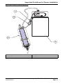
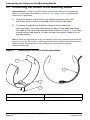
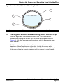
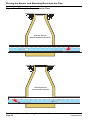
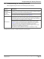
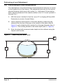
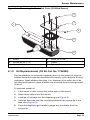
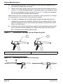
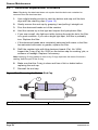
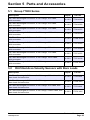
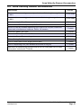
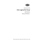
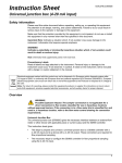
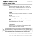
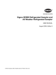
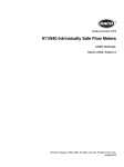
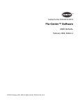
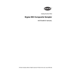
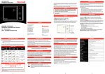
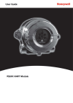
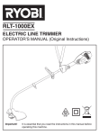
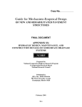
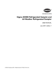
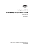
Catalog Number 7726018
Submerged Area/Velocity Sensor
USER MANUAL
September 2005 Edition 2
© Hach Company, 2005. All rights reserved. Printed in the U.S.A.
eac//te/dp
Visit us at www.hach.com
Table of Contents
Section 1 Specifications ........................................................................... 5
Section 2 General Information ................................................................. 7
2.1 Theory of Operation .............................................................................. 7
2.2 Sensor Overview ................................................................................... 7
Section 3 Installing the Sensor ................................................................ 9
3.1 Zeroing the Sensor ................................................................................ 9
3.2 Important Guidelines for Sensor Installation.......................................... 9
3.2.1 Proper Strain Relief of Sensor Cable ......................................... 10
3.3 Connecting the Sensor to the Mounting Bands ................................... 12
3.4 Placing the Sensor and Mounting Band into the Pipe ......................... 13
3.5 Compensating for Velocity Direction.................................................... 15
3.6 Performing a Level Adjustment............................................................ 16
Section 4 Sensor Maintenance............................................................... 17
4.1 Sensor Maintenance............................................................................ 17
4.1.1 Cleaning the Sensor (Oil-filled and Standard) ........................... 17
Cleaning the Sensor (Oil-filled and Non-oil) 17
4.1.2 Oil Replenishment (Oil Kit Cat. No. 7724800)............................ 19
4.2 Changing the Sensor Desiccant .......................................................... 21
4.2.1 Desiccant Replacement Procedure ........................................... 22
4.3 Hydrophobic Filter Description ............................................................ 23
4.4 Hydrophobic Filter Replacement Procedure........................................ 23
Section 5 Parts and Accessories .......................................................... 25
5.1 Group 77000 Series ............................................................................ 25
5.2 Oil-Filled Area Velocity Sensors with Bare Leads .............................. 25
5.3 Standard Area Velocity Sensors with Connectors .............................. 26
5.4 Standard Area Velocity Sensors with Bare Leads ............................... 26
5.5 Area Velocity Sensor Accessories....................................................... 27
Section 6 Contact Information for U.S.A. and Outside Europe ........... 29
Section 7 Contact Information for Europe ............................................ 30
Section 8 Limited Warranty .................................................................... 31
7726018TOC.fm
Page 3
Visit us at www.hach.com
Section 1 Specifications
Specifications are subject to change without notice. Performance will vary
depending on channel size, channel shape, and site conditions.
Velocity Measurement
For velocity performance specifications, refer to individual Sigma Automatic Sampler and
Flow Meter specifications.
Method
Doppler Ultrasound Twin 1 MHz piezoelectric crystals
Typical Minimum Depth
2 cm (0.8 in.)
Recommended Range
–1.52 to 6.10 m/s (–5 to 20 ft/s)
Level Measurement
Method
Pressure transducer with stainless steel diaphragm
Accuracy (static)1
±0.16% full scale ±1.5% of reading at constant temp (± 2.5 °C)
±0.20% full scale ±1.75% of reading from 0 to 30 °C (32 to 86 °F)
±0.25% full scale ±2.1% of reading from 0 to 70 °C (32 to 158 °F)
Velocity-Induced
Depth Error
Compensated based on pipe geometry and flow velocity.
Level Range
Standard: 0–3 m (0–10 ft)
Extended: 0–9 m (0–30 ft)
Allowable Level
Standard: 10.5 m (34.5 ft) Extended: 31.5 m (103.5 ft)
General Attributes
1
Air Intake
Atmospheric pressure reference is desiccant protected.
Operating Temperature
Range
0 to 70 °C (32 to 158 °F)
Level Compensated
Temperature Range
0 to 70 °C (32 to 158 °F)
Material
Noryl® outer shell with epoxy potting within
Power Consumption
≤1.2 W @ 12 VDC
Cable
Urethane sensor cable with air vent
Connector
Hard anodized; satisfies Military Spec 5015
Cable Lengths Available
Standard: 9, 15, 23, and 30.5 m (30, 50, 75, and 100 ft)
Custom: 30.75 m (101 ft) to 76 m (250 ft) maximum
Cable Diameter
0.91 cm (0.36 in.)
Dimensions
2.3 cm H x 3.8 cm W x 13.5 cm L (0.9 in. H x 1.5 in. W x 5.31 in. L)
Compatible Instruments
910, 920, 930, 930 T, 950, 980, 900 Max, 900 Max Refrigerated
Samplers, and 900 AWRS
For temperatures above 40 °C (104 °F) add ± 0.3 cm/°C (0.03 in./°F)
7726018specs.fm
Specifications
Page 5
Visit us at www.hach.com
Section 2 General Information
2.1 Theory of Operation
The Submerged Area/Velocity Sensor contains a pressure transducer for
level measurement and a pair of ultrasonic transducers for velocity
measurement. These two measurements are used to calculate flow in
open channels.
The flow meter measures the pressure of the water and converts it into a
level reading. The “wetted area” of the flow stream is then calculated using
this level reading and the user-entered channel geometry. The flow meter
then measures the Doppler shift in returned ultrasound and converts it into
a velocity reading. The “wetted area” multiplied by the velocity equals the
flow rate.
2.2 Sensor Overview
The sensor is available in two versions (Figure 1). The Non-oil sensor is used
for reasonably clear sites or in sites where the pipe can become dry.
The Oil-filled sensor is used for sites with high levels of biological growth, grit,
or silt. Do not use the Oil-filled sensor in a pipe that may become dry.
Figure 1
Non-oil and Oil-filled Sensors
1
1.
Non-oil Sensor
7726018geninfo.fm
2
2.
Oil-filled Sensor
General Information
Page 7
Visit us at www.hach.com
Section 3 Installing the Sensor
3.1 Zeroing the Sensor
The sensor has been factory-calibrated and compensated for temperature.
The sensor needs to be zeroed during each installation, but does not require
calibration. The sensor should be zeroed when moving it from one flow meter
or sample to another.
To zero the sensor:
1.
Install InSight version 5.7 or greater and start the program.
2.
From the InSight software menu, select Remote Programming.
3.
From the Real Time Operations list, select the level sensor to be
calibrated.
4.
Remove the probe from the liquid and place the sensor flat on the
tabletop or floor with the sensor (the plate with the holes) facing down
onto the surface.
5.
Press OK on the dialog box when complete.
3.2 Important Guidelines for Sensor Installation
• Do not install more than one sensor at a time in pipes less than 61 cm
(24 inches). Multiple sensors in smaller pipes can create turbulent or
accelerated flows near the sensors that may cause inaccurate
measurements.
• Mount the sensor as close as possible to the bottom of the pipe invert to
most accurately measure low velocity levels.
• Do not monitor flows in the invert of the manhole itself. The best sensor
location is 3 to 5 times the sewer diameter/height upstream of the invert.
• Locate monitoring sites as far from inflow junctions as possible to avoid
interference caused by combined flows.
• Avoid sites that contain flow obstacles within 2 to 4 pipe diameters in front
of the sensor installation (rocks, stones, pipe joints, valve stems, etc.) as
these will contribute to turbulence and generate high speed flows in the
immediate vicinity of the obstruction.
7726018install.fm
Installing the Sensor
Page 9
Important Guidelines for Sensor Installation
• Avoid any sites with slow moving flows that will encourage the buildup of silt
in the invert or channel. Excessive silting around the sensor may inhibit the
Doppler signal and decrease sensor accuracy, and may affect depth
measurement accuracy.
• Avoid sites with deep, rapid flows that will make it physically difficult or
dangerous to install the sensor.
• Avoid sites with high velocity, low-depth flows. Splash-over and excessive
turbulence will be present around the sensor and data may be inaccurate.
3.2.1
Proper Strain Relief of Sensor Cable
Attach the desiccant hub to the instrument handle to provide a strain relief for
the sensor cable and connector (Figure 2).
Important Guidelines for Sensor Installation
Page 10
7726018install.fm
Important Guidelines for Sensor Installation
Figure 2
Proper Strain Relief
1.
Lanyard
3.
Desiccant Hub
2.
Carabineer
4.
Flow Meter
7726018install.fm
Important Guidelines for Sensor Installation
Page 11
Connecting the Sensor to the Mounting Bands
3.3 Connecting the Sensor to the Mounting Bands
Important Note: If using an oil-filled sensor, replenish the oil prior to mounting the
sensor to a mounting band. Refer to section 4.1.2 on page 19 for oil replenishment
instructions, if applicable.
1.
Attach the sensor to the spring ring. Mounting bands come with
pre-drilled holes for direct mounting of the sensor to the band.
2.
To reduce the likelihood of debris collecting on the cable and
mounting band, route the cable along the edge of the band and fasten
the cable to the mounting band with nylon wire ties (Figure 3). The cable
should exit the tied area at, or near, the top of the pipe to keep it out of
the flow stream.
Note: If there is a large amount of silt in the bottom of the pipe, rotate the band until the
sensor is out of the silt (Figure 4), assuring that the sensor remains below the minimum
expected water level at all times. Silt should not be disturbed and must be
measured frequently.
Figure 3
Attaching the Sensor to the Mounting Band
1
4
2
3
1.
Spring Ring
3.
Screws (2)
2.
Sensor
4.
Nylon Wire Ties
Connecting the Sensor to the Mounting Bands
Page 12
7726018install.fm
Placing the Sensor and Mounting Band into the Pipe
Figure 4
Avoiding Silt when Mounting the Sensor
3
1
4
2
1.
Water
2.
Silt
3.
Pipe
4.
Sensor
3.4 Placing the Sensor and Mounting Band into the Pipe
Point the angle-face of the sensor into the flow. The manufacturer
recommends placing the sensor with the arrow pointing with the flow
(Figure 5). For other mounting configurations, see the appropriate flow
meter manual.
Slide the mounting band as far into the pipe as possible to eliminate
drawdown effects near the end of the pipe. Locate the sensor at the
bottom-most point in the channel. If excessive silt is present on the bottom
of the pipe, rotate the band in the pipe until the sensor is out of the silt.
7726018install.fm
Placing the Sensor and Mounting Band into the Pipe
Page 13
Placing the Sensor and Mounting Band into the Pipe
Figure 5
Placing the Sensor into the Flow
Manhole
Velocity Sensor
Normal Upstream Position
Manhole
Velocity Sensor
Downstream Position
Placing the Sensor and Mounting Band into the Pipe
Page 14
7726018install.fm
Compensating for Velocity Direction
3.5 Compensating for Velocity Direction
When programming the sensor the following may be selected:
Option1
Upstream
(recommended
for most
applications)
Description
Use this option at sites with fairly consistent velocities, and low to medium
turbulence. The flow stream over the sensor should be relatively straight,
with no drops or turns near the measurement point.
Mount the sensor in the pipe, beveled edge facing into the flow, where the
flow stream enters the measurement area (Figure 5).
Use this option when the sensor is installed downstream of the
measurement point (where the flow stream exits the site). This option is
useful when more than one flow stream enters a site and the combined
flow of all streams at a single exit point is measured.
Downstream
Mount the sensor in the downstream direction rather than the typical,
upstream direction. Mounting the sensor 'backwards' in this manner
(Figure 5) causes the velocity direction readings to be the opposite of
actual stream flow. By selecting the Downstream choice when
programming, the logger reverses the measured signal to show actual
flow direction (beveled edge downstream).
The maximum velocity obtained in this type of installation is 5 fps.
1 Additional options may be available depending on the flow meter or sampler used. Refer to
the appropriate flow meter or sampler manual for more information.
7726018install.fm
Compensating for Velocity Direction
Page 15
Performing a Level Adjustment
3.6 Performing a Level Adjustment
The manufacturer recommends doing a level adjustment whenever a sensor
is first installed into a flow stream. This adjustment accounts for the various
physical tolerance stack-ups in the system (i.e., thickness of the mounting
band, angular placement of the sensor relative to the “6 O’ clock” position in
the pipe, etc.)
1.
With the sensor installed in the flow, use a PC or display (950 and 980
flowmeter) to monitor Current Status.
2.
Take a physical measurement of the water depth by measuring the
distance from the top of the pipe to the surface of the water (item B,
Figure 6), and subtracting this number from the pipe diameter (item A,
Figure 6). The resulting number is the water depth (item C, Figure 6).
3.
Enter the physically-measured water depth into the software using the
Adjust Level function.
Figure 6
Measuring the Water Level
B
A
C
Performing a Level Adjustment
Page 16
7726018install.fm
Section 4 Sensor Maintenance
4.1 Sensor Maintenance
4.1.1
Cleaning the Sensor (Oil-filled and Standard)
Clean the transducer port when:
• Unexpected increase or decrease in flow or level trend occurs
• Level data are missing or incorrect but velocity data are valid.
• Excessive silt has deposited between the transducer and its
protective cover.
4.1.1.1 Cleaning the Sensor (Oil-filled and Non-oil)
Important Note: Do NOT interchange an oil-filled protective cover plate with a non-oil
cover plate. This will adversely affect level readings. It is possible to convert one type of
sensor to the other using the Oil Probe Conversion Kit (Cat. No. 7730000), refer to the
Oil Probe Conversion Kit Instruction Sheet, Cat. No. 7730089 for more information.
Important Note: When cleaning the transducer, use the most gentle technique
possible. Do not use sharp or pointed objects to remove sediment from the face of the
transducer. If you nick or dent the transducer, it will break!
1.
Soak the sensor in soapy water
Note: Do not soak the sensor in bleach. Bleach will permanently damage the sensor.
Refer to Table 1 for acceptable cleaning solutions.
Table 1 Cleaning Solutions
Acceptable
Unacceptable
Dish Detergent and Water
Concentrated Bleach
Window Cleaner
Kerosene
Isopropyl Alcohol
Gasoline
Dilute Acids
Aromatic Hydrocarbons
2.
Remove the screws from the protective cover (Figure 7).
3.
Remove the cover and gasket.
4.
Carefully swirl the sensor in an appropriate cleaning solution to remove
soil. Use a spray or squeeze bottle to wash away heavier deposits.
5.
Clean the gasket and cover. Replace the gasket (Cat. No. 7722000) if it
is torn or damaged. Level readings will be adversely affected if the
gasket is damaged or not installed.
6.
Reattach the gasket and cover (note orientation in Figure 7). Tighten the
screws until the gasket starts to compress.
7726018maint.fm
Sensor Maintenance
Page 17
Sensor Maintenance
7.
If using an oil-filled sensor, continue to Oil Replenishment (Oil Kit Cat.
No. 7724800) on page 19.
Figure 7
Removing the Protective Cover (Non-Oil Sensor)
2
1
3
4
5
1.
Sensor
4.
Gasket
2.
Screws (#6–32 x 5/16)
5.
Pressure Transducer
3.
Protective Cover
Sensor Maintenance
Page 18
7726018maint.fm
Sensor Maintenance
Figure 8
Removing the Protective Cover (Oil-filled Sensor)
2
3
1
4
5
6
1.
Sensor
2.
Screws (#6–32 x
3.
Protective Cover
4.1.2
5/16)
4.
Screw, set, #2-56
5.
Gasket
6.
Pressure Transducer
Oil Replenishment (Oil Kit Cat. No. 7724800)
The manufacturer recommends inspecting the oil in the sensor for large air
bubbles during the customer-scheduled service duty cycle, and prior to every
installation. Small bubbles (less than ¼-in. diameter) of air within the oil do
not affect performance. Larger bubbles may minimize the anti-fouling benefit
of the oil.
To replenish sensor oil:
1.
If the sensor is new, remove the yellow tape on the sensor.
2.
Remove any debris from the sensor.
3.
Load the oil cartridge into the dispensing gun (Figure 9).
4.
Twist the feed tube onto the cartridge and attach the syringe tip to the
feed tube (Figure 10).
5.
Press the dispenser gun handle to purge any air bubbles from the
syringe tip.
7726018maint.fm
Sensor Maintenance
Page 19
Sensor Maintenance
6.
Remove the set screw in the transducer cover with the supplied 0.035
hex wrench. Retain the set screw.
7.
Slowly insert the syringe tip into the set screw hole and dispense the oil
(Figure 11). While dispensing the oil, hold the probe at an angle to allow
the air to be pushed out the side port (Figure 11). Continue to dispense
the oil until all the air bubbles are removed.
Note: Slowly insert the syringe tip and do not dispense oil during insertion or damage
to the transducer may occur if too much pressure is applied.
8.
Continue to dispense the oil while removing the syringe from the set
screw hole to prevent air bubbles. Replace the set screw until it is flush
with the transducer cover and remove any excess oil around the screw
hole or on the sensor.
9.
Clean the entire probe and place a piece of electrical tape over the side
port to prevent oil from leaking out. Remove the tape from the sensor
prior to zeroing and installing the sensor.
Figure 9
Loading the Cartridge into the Dispensing Gun
1
1.
Dispensing Gun
Figure 10
2
2.
Silicone Oil Cartridge
Attaching the Feed Tube and Syringe
Sensor Maintenance
Page 20
7726018maint.fm
Sensor Maintenance
Figure 11
Oil Replenishment
1
3
2
4
1.
Sensor
3.
Side port
2.
Set screw
4.
Syringe
4.2 Changing the Sensor Desiccant
The desiccant canister contains beads of silica gel which ensure proper
orientation of the pressure transducer. When the beads are blue, they can
remove moisture from the air. When they are pink, they are saturated and
cannot absorb any more moisture from the air, and they must be replaced
immediately.
Important Note: When the beads begin to turn pink, replace or rejuvenate the beads.
Permanent damage to the sensor may occur if the desiccant is not maintained. Never
operate the sensor without the proper desiccant. When rejuvenating beads, remove
them from the canister and heat at 100–180 °C (212–350 °F) until the beads turn blue.
If the beads do not turn blue, replace them with new beads. Do not heat the canister.
7726018maint.fm
Changing the Sensor Desiccant
Page 21
Sensor Maintenance
4.2.1
Desiccant Replacement Procedure
Note: Replacing the desiccant does not require that the desiccant container be
removed from the desiccant box.
1.
Use a slight twisting motion to twist the bottom end-cap until its slots
align with the retaining clips (Figure 12).
2.
Gently remove the end cap by grasping it and pulling it straight out.
3.
Pour the desiccant beads out of the canister.
4.
Hold the canister up to the light and inspect the hydrophobic filter.
• If you see a small, dim light spot while looking through the hole, the filter
is in good condition. If you see a bright light spot, the filter is probably
torn. Replace the filter.
• If the desiccant beads were completely saturated with water or the filter
has saturated with water or grease, replace the filter.
5.
Refill the canister tube with blue desiccant beads (Cat. No. 3624).
Inspect the O-ring (Cat. No. 5252) on the bottom cap for cracking, pits, or
evidence of leakage. Replace if necessary.
Note: Applying O-ring grease to new or dry O-rings improves the ease of insertion,
sealing, and life span of the O-ring.
6.
Make sure that the O-ring is clean and free of dirt or debris before
replacing the end cap.
7.
Reinstall the end cap.
Figure 12
1.
Removing the Bottom End Cap
End Cap
Changing the Sensor Desiccant
Page 22
2.
Desiccant Container
7726018maint.fm
Sensor Maintenance
4.3 Hydrophobic Filter Description
A single Teflon® hydrophobic filter (Cat. No. 3390) is installed in the top of the
canister to prevent liquid from entering the vent tube.
For best performance and to avoid grease buildup on the filter during
submergence or surcharge conditions, hang the canister vertically so that the
end facing the sensor points downward.
Note: The Hydrophobic Filter may need replacement at any time the cartridge is
submerged or exposed to excess moisture. Refer to section 4.4.
4.4 Hydrophobic Filter Replacement Procedure
1.
Disconnect the tubing from the top of the desiccant canister.
2.
Unscrew the hex-head tubing nipple from the top of the canister and
discard the old filter.
3.
Discard any remnants of Teflon tape from the nipple’s threads. Reapply
two turns of Teflon tape (Cat. No. 10851-45) to the threads, pulling the
tape into the threads until it conforms to the shape of the threads.
4.
Place a new filter over the hole. Make sure that the smooth side of the
filter faces the inside of the canister (Figure 13).
5.
Place the threaded nipple on top of the filter.
6.
With a slight pressure, press the filter into the hole with the nipple
threads and begin threading the nipple into the hole. The filter will deflect
upward and feed completely into the thread until it disappears. The filter
must rotate with the nipple as it is threaded into the cap. If it does not, it is
torn. Start over with a new filter.
7.
Inspect the installation. In the upper cap, a small, dim light spot should
be visible when held up to the light. A bright spot indicates a torn filter.
Start over with a new filter.
Figure 13
Replacing the Hydrophobic Filter
1
1.
Filter, smooth side down
7726018maint.fm
3
2
2.
Hex-head tubing nipple
3.
Finished assembly.
Hydrophobic Filter Description
Page 23
Visit us at www.hach.com
Section 5 Parts and Accessories
5.1 Group 77000 Series
Description
Depth
Cat. No.
Oil-Filled Submerged AV Sensor, 0–10 ft range, 30 ft cable,
with connector
0–10 ft
77064-030
Oil-Filled Submerged AV Sensor, 0–10 ft range, 50 ft cable,
with connector
0–10 ft
77064-050
Oil-Filled Submerged AV Sensor, 0–10 ft range, 75 ft cable,
with connector
0–10 ft
77064-075
Oil-Filled Submerged AV Sensor, 0–10 ft range, 100 ft cable,
with connector
0–10 ft
77064-100
Oil-Filled Submerged AV Sensor, 0–10 ft range, custom cable,
with connector
0–10 ft
77064-XXX
Oil-Filled Submerged AV Sensor, 0–30 ft range, 30 ft cable,
with connector
0–30 ft
77074-030
Oil-Filled Submerged AV Sensor, 0–30 ft range, 50 ft cable,
with connector
0–30 ft
77074-050
Oil-Filled Submerged AV Sensor, 0–30 ft range, 75 ft cable,
with connector
0–30 ft
77074-075
Oil-Filled Submerged AV Sensor, 0–30 ft range, 100 ft cable,
with connector
0–30 ft
77074-100
Oil-Filled Submerged AV Sensor, 0–30 ft range, custom cable,
with connector
0–30 ft
77074-XXX
5.2
Oil-Filled Area Velocity Sensors with Bare Leads
Description
Depth
Cat. No.
Oil-Filled Submerged AV Sensor, 0–10 ft range, 30 ft cable, with
bare leads for barrier box
0–10 ft
77264-030
Oil-Filled Submerged AV Sensor, 0–10 ft range, custom cable, with
bare leads for barrier box
0–10 ft
77264-XXX
Oil-Filled Submerged AV Sensor, 0–30 ft range, 30 ft cable, with
bare leads for barrier box
0–30 ft
77274-030
Oil-Filled Submerged AV Sensor, 0–30 ft range, custom cable, with
bare leads for barrier box
0–30 ft
77274-XXX
7726018parts.fm
Parts and Accessories
Page 25
Standard Area Velocity Sensors with Connectors
5.3
Standard Area Velocity Sensors with Connectors
Description
Depth
Cat. No.
Submerged AV Sensor, 0–10 ft range, 30 ft cable, with connector
0–10 ft
77065-030
Submerged AV Sensor, 0–10 ft range, 50 ft cable, with connector
0–10 ft
77065-050
Submerged AV Sensor, 0–10 ft range, 75 ft cable, with connector
0–10 ft
77065-075
Submerged AV Sensor, 0–10 ft range, 100 ft cable, with connector
0–10 ft
77065-100
Submerged AV Sensor, 0–30 ft range, custom cable,
with connector
0–10 ft
77065-XXX
Submerged AV Sensor, 0–30 ft range, 30 ft cable, with connector
0–30 ft
77075-030
Submerged AV Sensor, 0–30 ft range, 50 ft cable, with connector
0–30 ft
77075-050
Submerged AV Sensor, 0–30 ft range, 75 ft cable, with connector
0–30 ft
77075-075
Submerged AV Sensor, 0–30 ft range, 100 ft cable, with connector
0–30 ft
77075-100
Submerged AV Sensor, 0–30 ft range, custom cable,
with connector
0–30 ft
77075-XXX
5.4 Standard Area Velocity Sensors with Bare Leads
Description
Depth
Cat. No.
Submerged AV Sensor, 0–10 ft range, 30 ft cable, with bare leads
for barrier box
0–10 ft
77265-030
Submerged AV Sensor, 0–10 ft range, custom cable, with bare
leads for barrier box
0–10 ft
77265-XXX
Submerged AV Sensor, 0–30 ft range, 30 ft cable, with bare leads
for barrier box
0–30 ft
77275-030
Submerged AV Sensor, 0–30 ft range, custom cable, with bare
leads for barrier box
0–30 ft
77275-XXX
Standard Area Velocity Sensors with Connectors
Page 26
7726018parts.fm
Area Velocity Sensor Accessories
5.5 Area Velocity Sensor Accessories
Description
Cat. No.
Custom cable connecting sensor to junction box. Cable lengths range from
1–99 ft
77155-PRB
Custom cable connecting junction box to hub. Cable lengths range from
1–99 ft
77155-HUB
Hub Assembly for Bare Wire
77228-00
Silicon oil dual 50-mL oil pack only. Refills 100 sensors
7724700
Silicon oil refill kit includes dispensing tool, dual 50-mL oil pack, instruction
sheet and miscellaneous hardware. Refills 100 sensors
7724800
Instruction Sheet, Oil Fill Kit
7724789
Instruction Sheet, Bare Wire AV Probe
7725089
Instruction Sheet, Firmware Upgrade
7726089
Silicon Potting Gel Kit
7725600
Gel Fill (order three to fill a single junction box)
7729800
Gel Fill Dispensing Gun (also doubles as silicone oil fill gun)
7715300
Retrofit kit for transforming a sensor with a non-oil cover plate into Oil filled
cover plate. Includes kit 77248-00
7730000
7726018parts.fm
Area Velocity Sensor Accessories
Page 27
Visit us at www.hach.com
Section 6 Contact Information for U.S.A.
and Outside Europe
Ordering Information for the U.S.A.
By Telephone:
By Mail:
6:30 a.m. to 5:00 p.m. MST
Monday through Friday
(800) 227-HACH
(800)-227-4224
By Fax:
Hach Company
P.O. Box 389
Loveland, Colorado 80539-0389
U.S.A
Ordering information by E-mail:
(970) 461-3914
[email protected]
Information Required
• Hach account number (if available)
• Billing address
• Your name and phone number
• Shipping address
• Purchase order number
• Catalog number
• Brief description or model number
• Quantity
Ordering Information for Outside the U.S.A. and Europe
Hach Company maintains a worldwide network of dealers and distributors. To locate
the representative nearest you, send e-mail to [email protected] or visit
www.hach.com.
Technical Support
Technical and Customer Service Department personnel are eager to answer
questions about our products and their use. In the U.S.A., call 1-800-227-4224 or
email [email protected]. Outside the U.S.A. and Europe, send e-mail to
[email protected].
Repair Service
Authorization must be obtained from Hach before sending any items for repair.
Please contact the Hach Service Center serving your location.
Hach Company
P.O. Box 389
Loveland, Colorado, 80539-0389 U.S.A.
Telephone: 1-800-635-4567 or (970) 669-3050
Fax: (970) 669-2932
7226018contact.fm
Contact Information for U.S.A. and Outside Europe
Page 29
Section 7 Contact Information for Europe
For technical support, repair service, and ordering information please refer to the
contact information below for your specific country. For additional information, visit
www.hach-lange.com.
Austria
Dr. Bruno Lange Ges. MBH
Industriestraße 12
A - 3200 Obergrafendorf
Tel. +43 (0)27 47 74 12
Fax +43 (0)27 47 42 18
[email protected]
Germany
Dr. Bruno Lange GmbH
& CO. KG
Willstätterstr. 11
D-40549 Düsseldorf
Tel. +49 (0)2 11 52 88-0
Fax +49 (0)2 11 52 88-143
[email protected]
The Netherlands
Dr. Lange Nederland B.V.
Laan an Westroijen 2a
NL-4003 AZ Tiel
Tel. +31 (0) 3 44 63 11 30
Fax +31 (0) 3 44 63 11 50
[email protected]
Belgium
Dr. Lange
Motstraat 54
B-2800 Mechelen
Tel. +32 (0)15 42 35 00
Fax +32 (0)15 41 61 20
[email protected]
Great Britain
Hach Lange LTD
Lennox Road
Basingstoke
Hampshire, RG22 4AP
Tel. +44 (0)12 56 33 34 03
Fax +44 (0)12 56 33 07 24
[email protected]
Spain/Portugal
Hach Lange S.L.U.
c/ Araba, 45. Apdo. 220
E-20800 Zarauz/Guipùzcoa
Tel. +34 9 43 89 43 79
Fax +34 9 43 13 02 41
[email protected]
Denmark
Dr. Lange Danmark A/S
Jernhoolmen 34-40
DK-2650 Hvidovre
Tel. +45 (0)36 77 29 11
Fax +45 (0)36 77 49 11
[email protected]
Italy
Dr. Bruno Lange s.r.I.
Via Riccione, 14
I-20156 Milano
Tel. +39 02 39 23 14-1
Fax +33 02 39 23 14-39
[email protected]
Sweden
Hach Lange AB
Vinthundsvägen 159A
S-128 62 Sködal
Tel. +46 (0)8 7 98 05 00
Fax +46 (0)8 7 98 05 03
[email protected]
France
Hach Lange
Hach SAS
33 Rue du Ballon
F-93165 Noisy Le Grand
Tel. +33 (0)1 48 15 80 80
Fax +33 (0)1 48 15 80 00
[email protected]
Poland
Hach Lange sp.zo.o.
ul. Opolska 143 a
PL-52-013 Wroclaw
Tel. +48 71 3 42 10 -81
Fax +48 71 3 42 10-79
[email protected]
Switzerland
Dr. Bruno Lange AG
Juchstrasse 1
CH-8604 Hegnau
Tel. +41(0)1 9 45 66 10
Fax +41(0)1 9 45 66 76
[email protected]
Contact Information for Europe
Page 30
7226018contact.fm
Section 8 Limited Warranty
Hach Company warrants its products to the original purchaser against any defects that are due
to faulty material or workmanship for a period of one year from date of shipment unless
otherwise noted in the product manual.
In the event that a defect is discovered during the warranty period, Hach Company agrees that,
at its option, it will repair or replace the defective product or refund the purchase price
excluding original shipping and handling charges. Any product repaired or replaced under this
warranty will be warranted only for the remainder of the original product warranty period.
This warranty does not apply to consumable products such as chemical reagents; or
consumable components of a product, such as, but not limited to, lamps and tubing.
Contact Hach Company or your distributor to initiate warranty support. Products may not be
returned without authorization from Hach Company.
Limitations
This warranty does not cover:
• Damage caused by acts of God, natural disaster, labor unrest, acts of war (declared or
undeclared), terrorism, civil strife or acts of any governmental jurisdiction
• Damage caused by misuse, neglect, accident or improper application or installation
• Damage caused by any repair or attempted repair not authorized by Hach Company
• Any product not used in accordance with the instructions furnished by Hach Company
• Freight charges to return merchandise to Hach Company
• Freight charges on expedited or express shipment of warranted parts or product
• Travel fees associated with on-site warranty repair
This warranty contains the sole express warranty made by Hach Company in connection with
its products. All implied warranties, including without limitation, the warranties of
merchantability and fitness for a particular purpose, are expressly disclaimed.
Some states within the United States do not allow the disclaimer of implied warranties and if
this is true in your state the above limitation may not apply to you. This warranty gives you
specific rights, and you may also have other rights that vary from state to state.
This warranty constitutes the final, complete, and exclusive statement of warranty terms and no
person is authorized to make any other warranties or representations on behalf of Hach
Company.
Limitation of Remedies
The remedies of repair, replacement or refund of purchase price as stated above are the
exclusive remedies for the breach of this warranty. On the basis of strict liability or under any
other legal theory, in no event shall Hach Company be liable for any incidental or consequential
damages of any kind for breach of warranty or negligence.
7226018contact.fm
Limited Warranty
Page 31
Visit us at www.hach.com