1
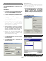
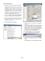
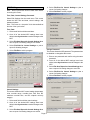
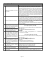
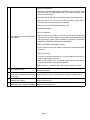
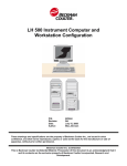
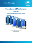
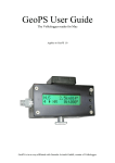
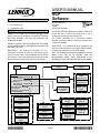
USER’S MANUAL
NCP
Software
Packing List
Package 1 of 1 contains:
MISCELLANEOUS
505,088M
7/2006
Supersedes 504,420M
1− CD Version 2.08
1− Registration card
Application
Litho U.S.A.
E2006
For dial−up connection, Modem Kit (94L62) is required to
access the NCP. Connect the modem kit to the L
Connection network bus and a phone line.
For TCP/IP connection, an L Connection Network
Ethernet Converter (76M77) is required to access the L
Connection Network.
Network Control Panel (NCP) Software (96L82) is used
locally or remotely to monitor the L Connection® Network
and setup programs with new day schedules and
holidays to the NCP.
Holidays, programs, and day schedules can be created
off−site, saved to a text file, transported to the job site, and
uploaded to the NCP.
IMPORTANT − If a password has been enabled at the
NCP, the same password is required to download NCP
programs and settings and clear NCP alarms.
IMPORTANT − For serial port connection, PC to L
Connection Converter Kit (96L78) is required to access
the NCP. Connect the converter between the PC RS232
port and the L Connection network port on the NCP using
the spiral phone cord provided with the converter kit.
Note − The discharge air temperature displayed in the Unit
Status screen may not be accurate. Move the
factory−installed sensor further downstream of the
discharge air to get a more accurate discharge air reading.
SOFTWARE SCREEN INDEX
Start
Page 2
Manuals
Page 2
Main Menu
Connect to Network With NCP
Live Overview
Data Logging & Graphing
Synchronize
Edit Programs / Schedules
Edit Settings
Build Schedules Offline
Open Reports
Open Data Logging Reports
Exit NCP Software
All HVAC Units/
Zones
Page 6
Data Logging
and Graphing
Page 8
Holidays
Page 4
HVAC Programs
Page 4
HVAC Day Schedules
Page 4
BC Programs
Page 5
Time, Date
Page 11
Control Settings
Page 11
Change Password
Page 11
BC Day Schedules
Page 5
07/06
*2P0706*
Network Phone Book
Page 3
Set Parameters
Page 3
HVAC Unit/Zone
Status
Pages 6 and 7
Alarms
Pages 6 and 7
Temperature/
Humidity Chart
Page 7
Setup
Page 9
Holidays
Page 10
Special Events
Page 10
HVAC Programs
Page 10
BC Programs
Page 10
HVAC Day
Schedules
Page 10
BC Day
Schedules
Page 10
505,088M
Page 1
*P505088M*
Minimum System Requirements
The following are minimum PC system requirements
when operating the Network Control Panel software:
1− IBM compatible PC with Pentium or higher processor.
2− Microsoft® Windows® 95, 98, Me, NT®, 2000, or XP.
3− 256 MB RAM (more memory may be required to run
additional applications simultaneously).
4− Requires at least 20 MB of free hard drive space.
5− VGA or higher resolution monitor (screen resolution
must be 800 X 600 or higher and 256 colors).
6− CD−ROM drive.
7− Mouse or compatible pointing device.
8− Serial COM port for serial port connections.
9− PC modem for dial−up connections.
10− Ethernet port for TCP/IP connections.
11− Microsoft Outlook for alarm email notification.
12− Microsoft Excel for datalogging and graphing.
WARNING
Main Menu
Only three selections are active at this time.
Connect to Network with NCP
Select Connect to Network with NCP when on−site,
plugged into the network.
Improper installation, adjustment, alteration, service or maintenance can cause property damage,
personal injury or loss of life. Installation and service must be performed by a qualified installer or
service agency.
Build Schedules Offline
Installation
Open Reports
Install the NCP software to a PC hard drive:
1− Place the CD in the CD−ROM drive and it will
auto−run. If the CD does not auto−run, select
Start−Run, browse the CD, and locate the
Setup.exe" file. Click OK.
2− Follow the installation instructions on the screen.
Running the Software
Select Start − Programs − Lennox − Commercial
Controls − L Connection Software or double click the L
Connection Software icon on the desktop if one has been
created.
If the program is running correctly the following start−up
screen will be displayed.
Click on User’s Manual to view manuals; click on
Network Control Panel Software to start the NCP
software; or click Exit to exit program. Select Network
Control Panel Software to run the software. The main
menu will appear.
Note − Unit Controller Software will only appear if it is
installed (purchased separately).
Page 2
This selection is used to create new programs when not
connected to the network. New programs may be saved
to a file and uploaded to the NCP on−site at a later time.
Access previously created reports.
Open Data Logging Reports
Access previously created data logging reports in Excel.
Network Phone Book
Connect to Network
Select Connect to Network. The Set Parameters screen
will appear.
Set Parameters
1− For serial port connections, select appropriate COM
PORT from the Connect Using pull−down menu.
2− For dial−up connections, select appropriate modem
from the Connect Using pull−down menu.
The Network Phone Book is used to store information
on different networks (network name, address, phone
number, and COM port used).
1− Select the appropriate network in the list on the left
side. Click Edit Network to edit; select Add New
Network to add a new network; select Remove
Network to remove the network permanently; select
Save Network Phone Book As to save the network
phone book to a file; select Print Network Phone
Book to print book.
2− Click Done when finished.
3− For TCP/IP connections, select TCP/IP from the
Connect Using pull−down menu.
4− Select the network name to be accessed. If a network
list has not already been created, only New
Network−Autopoll will be displayed. Network name
may be assigned in the Network List.
5− Background logging to create a zone temperature
and relative humidity chart is enabled by default.
Select the box to disable background logging if a
temperature and humidity chart is not needed.
6− Enter or verify the phone number. Enter any
additional numbers to access an outside line or long
distance call and disable call waiting.
Open Reports
7− Click Network Phone Book to access the network
phone book database.
Select Open Reports from the main menu to view or print
previously stored reports.
8− Click Connect when ready to communicate. The
main menu will appear.
Open Data Logging Reports
Select Open Data Logging Reports from the main menu
to view or print previously generated data logging reports.
Page 3
Setup Program / Schedule Template
These screens are used to create, view, and edit
Holidays, HVAC Programs, HVAC Day Schedules, BC
Programs, and BC Schedules.
Holidays
1− Select Holidays tab to add or delete holidays. Refer
to the following screen.
4− Select Delete Program button to delete the program
from the list.
NOTE − Default programs A and B can be modified but not
deleted.
5− To edit the day schedule, enter a new number or use
the pulldown menu. Press the tab or enter key to
save the new settings.
6− Once all Holidays, Programs, and Day Schedule
settings are complete, select File−Save NCP
Program File to save the new program to a file. Once
on−site, refer to the Edit Programs/Schedules
section to upload the new program to the NCP.
7− Select File−Open NCP Program file to view and edit
an existing program file.
8− Select File−Open Report for Programs, Day
Schedules and Holidays to view a previously
saved report.
9− Select File−Save Report for Programs, Day
Schedules and Holiday As to save the current report.
10− Select File−Print Report for Programs, Day
Schedules and Holidays to print the report.
HVAC Day Schedules
This screen shows the day schedules for HVAC units.
2− To add a holiday, change the calender to the
appropriate month, highlight the appropriate day, and
click on Add Holiday.
3− To delete an existing holiday, highlight the holiday in
the holiday list and click Delete Holiday.
HVAC Programs
This screen shows the programs, day schedules, and
holidays for HVAC units.
1− Select the program in the Program List to view the
settings.
2− Select Add Program button to add new programs.
3− Select Copy Program button to copy one program to
another.
Page 4
1− Select the day schedule in the Day Schedule List to
view.
2− Select Add Day Schedule button to add a new day
schedule.
3− Select Copy Day Schedule button to copy one day
schedule to another.
4− Select Delete Day Schedule button to delete a day
schedule (schedules 1 and 2 cannot be deleted).
5− Select the Edit button to the left of the time fields to
edit the time, heat setpoint, cool setpoint, and
occupied settings. Press the tab or enter key to save
the new settings.
6− Select the X button to the right of the occupied field
to delete the time in that row. The time in the first row
cannot be deleted for all day schedules.
7− Once all Holidays, Programs, and Day Schedule
settings are complete, Select File−Save NCP
Program File to save the new program to a text file.
Once
on−site,
refer
to
the
Edit
Programs/Schedules section to upload the new
program to the NCP.
8− Select File−Open NCP Program File to view an
existing program file.
9− Select File−Open Report for Programs, Day
Schedules and Holidays to view a previously
saved report.
8− Select File−Open Report for Programs, Day
Schedules and Holidays to view a previously
saved report.
9− Select File−Save Report for Programs, Day
Schedules and Holiday As to save the current report.
10− Select File−Print Report for Programs, Day
Schedules and Holidays to print the report.
BC Day Schedules
This screen shows the day schedules for Building
Controllers.
10− Select File−Save Report for Programs, Day
Schedules and Holiday As to save the current report.
11− Select File−Print Report for Programs, Day
Schedules and Holidays to print the current report.
BC Programs
This screen shows the programs, day schedules, and
holidays for Building Controllers.
1− Select the program in the Program List to view the
settings.
2− Select Add Program button to add new programs.
3− Select Copy Program button to copy one program to
another.
4− Select Delete Program button to delete the program
from the list.
NOTE − Default programs A and B can be modified but not
deleted.
5− To edit the day schedule, enter a new number or use
the pulldown menu. Press the tab or enter key to
save the new settings.
6− Once all Holidays, Programs, and Day Schedule
settings are complete, select File−Save NCP
Program File to save the new program to a file. Once
on−site, refer to the Edit Programs/Schedules
section to upload the new programs to the NCP.
7− Select File−Open NCP Program file to view and edit
an existing program file.
Page 5
1− Select the day schedule in the Day Schedule List to
view.
2− Select Add Day Schedule button to add a new day
schedule.
3− Select Copy Day Schedule button to copy one day
schedule to another.
4− Select Delete Day Schedule button to delete a day
schedule (schedules 1 and 2 cannot be deleted).
5− Select the Edit button to the left of the time fields to
edit the time and action settings. Press the tab or
enter key to save the new settings.
6− Select the X button to the right of the occupied field
to delete the time in that row. The time in the first row
cannot be deleted for all day schedules.
7− Once all Holidays, Programs, and Day Schedule
settings are complete, Select File−Save NCP Program
File to save the new program to a text file. Once on−site,
refer to the Edit Programs/Schedules section to
upload the new program.
8− Select File−Open NCP Program File to view an
existing program file.
9− Select File−Open Report for Programs, Day
Schedules and Holidays to view a previously
saved report.
10− Select File−Save Report for Programs, Day
Schedules and Holiday As to save the current report.
11− Select File−Print Report for Programs, Day
Schedules and Holidays to print the current report.
Status, Alarms, and Chart
Live Overview
Select Live Overview from the main menu. This screen
shows all the HVAC units/zones/building controllers
found in the network and gives an overview.
Note − This screen is in a listening" mode and will update
as the status changes.
These screens show the status, alarms, and chart for the
address highlighted in the NCP Network list only.
When the highlighted address is for an HVAC unit or zone,
these screens show the status (compressors, number of
stages, thermostat or zone sensor mode, etc.), alarms,
and temperature/humidity chart for the zone selected.
Note − These screens are in a listening" mode and will
update as unit status changes.
1− View individual HVAC unit/zone/building controller
status, alarm, and chart, by double clicking on the
Type" to the left of the appropriate address.
2− Select File−Rename Network to rename and save
network information in the network phone book.
3− Select File−Open Status Report to view a previously
saved report.
4− Select File−Save Status Report As to save a report.
5− Select File−Print Status Report to print a status
report.
6− Select File−Back to NCP Main Menu to return to
main menu.
Page 6
When the highlighted address is for a Building Controller,
these screens show the status (outputs, temperatures,
and analog inputs) and alarms of the Building Controller
selected.
Status
1− View the status of other addresses by selecting a
different address in the NCP Network list.
2− Select File−Retrieve Alarms to retrieve alarms.
Alarms screen is not accessible before downloading
alarms.
3− Select File−Enable Alarm Email Notification to
setup the alarm email notification options.
4− Select File−Open Status/Alarm Report to view a
previously saved status or alarm report.
5− Select File−Save Alarm Report As (All Addresses)
to save an alarm report for all addresses in the
network. Alarms must be retrieved from the NCP
before this selection is available.
6− Select File−Print Alarm Report (All Addresses) to
print an alarm report for all addresses in the network.
Alarms must be retrieved from the NCP before this
selection is available.
7− Select File−Save Status Report As (All Addresses)
to save a report.
8− Select File−Print Status Report (All Addresses) to
print a status report.
9− Select File−Back to NCP Main Menu to return to
main menu.
Note − The discharge air temperature displayed in the
Status screen may not be accurate. Move the
factory−installed sensor further downstream of the
discharge air to get a more accurate discharge air reading.
Alarms
Alarms must be retrieved from the NCP before this
selection is available.
11− Select File−Save Status Report As (All Addresses)
to save a report.
12− Select File−Print Status (All Addresses) to print a
status report.
13− Select File−Back to NCP Main Menu to return to
main menu.
Chart
1− Select the Chart tab to view a log of zone temperature
and relative humidity readings.
2− View the temperature and humidity charts of other
units by selecting a different address in the NCP
Network list.
3− The NCP software has to be running to create a chart.
1− Select File−Retrieve Alarms from the Status screen
A chart will display up to 10 hours of temperature and
before viewing alarms. Select the Alarms tab to view
humidity readings.
alarms.
4− Select File−Start/Stop Background Log (All
2− Select the alarm to view a detailed description of the
Zones) to start or stop the temperature and humidity
problem and the resulting action.
log. Logging is enabled by default; if a chart is not
3− Highlight other addresses in the NCP Network list to
needed it can also be disabled from the Set
view the alarms of other addresses on the network.
Parameters screen.
4− Select Clear Alarms to delete all alarms stored in the
NCP memory for the unit highlighted in the NCP
Network list. If a password has been enabled in the
NCP, a prompt will request the password.
5− Select Save Alarms to save the current alarms to a
text file.
6− Select Print Alarms to print the current alarms.
7− Select the Status tab to view the status.
8− Select File−Open Status/Alarm Report to view a
previously saved report.
9− Select File−Save Alarm Report As (All Addresses)
to save an alarm report for all addresses in the
network. Alarms must be retrieved from the NCP
before this selection is available.
10− Select File−Print Alarm Report (All Addresses) to
print an alarm report for all addresses in the network.
Page 7
Alarm Email Notification
Data Logging and Graphing
1− Highlight a unit controller to view the list of alarms.
Select the alarms from the list to receive email
notification when the alarm occurs for the
highlighted controller. All alarms can be selected
for the highlighted controller by clicking the Select
All Alarms button. All the lockout alarms can be
selected for the highlighted controller by clicking
the Select Lock Out Alarms Only button.
2− Check the Enable Alarm Email Notification
checkbox to activate the email notification feature.
3− Enter the email addresses where the alarm email
notifications will be sent. Multiple addresses must be
separated by a semicolon.
4− Click the Done button when finished.
1− Select the data to be logged for the highlighted
unit/zone.
2− Setup the data logging rate by choosing the logging
interval, logging period, and start date/time. PC
date/time can be used by checking Use PC Date &
Time checkbox. This will start the data logging
immediately after clicking Start Logging button.
3− Enter a filename for the data logging file.
4− Click Start Logging button to start logging data.
5− A progress bar shows the data logging status.
6− Logging can be stopped at anytime by clicking Stop
button.
7− Click Excel button to view the logged data and graph.
Page 8
Synchronize
Select Synchronize to retrieve settings, programs,
schedules, and holidays from the NCP. If a password has
been enabled in the NCP, a prompt will request the
password.
Edit Programs/Schedules
Note − Select Synchronize from the main menu before
accessing this screen.
Setup
Select Edit Programs/Schedules from the main menu.
These screens show the zone setup for the address
highlighted in the NCP Network list only.
When the highlighted address is for an HVAC unit, this
screen shows the zone setup (sensor temperature,
setpoints, NCP mode, control mode, etc.) of the HVAC
unit selected. To access the zone setup on more than one
zone, select a zone from the drop down box.
Note − This screen is a snapshot" of the data available at
the time of the synchronize.
1− Select other addresses in the NCP Network List to
view the Setup of other addresses on the network.
2− Use the tab or enter key after changing a setting to
save the new setting. The tab key is also used to
toggle through the Unit Setup fields.
3− Select Synchronize to send all changes to the NCP.
IMPORTANT − Time and date should already be set at the
NCP. If not, see Edit NCP Settings to set time and date.
4− Select File−Open NCP Program File to load the
programs from a previously saved file.
5− Select File−Save NCP Program File to save the
current programs to a text file.
6− Select File−Open Report for Status, Programs and
Day Schedule to view a previously saved report.
Note − This screen is a snapshot" of the data available at
the time of the synchronize.
When the highlighted address is for a Building Controller,
this screen shows the status and setup (outputs,
temperatures, and analog inputs) of the Building
Controller selected.
Page 9
7− Select File−Save Report for Status, Programs and
Day Schedule As to save a report of all programs.
8− Select File−Print Report for Status, Programs, and
Day Schedule to print a report of all programs.
9− Select File−Exit to exit the program. Make sure
changes have been sent before exiting.
NCP Mode (HVAC Units)
Special Events
This field displays and edits whether the NCP is set to
control or monitor the unit. When Control" is displayed,
the NCP is controlling the setpoints. When Monitor" is
displayed, the NCP is monitoring the unit only and not
controlling the setpoints.
1− Select Special Events tab to add or delete special
events.
2− To add a special event, name the event, select a
controller, set the date, start time, and duration for the
event, and click on Add Event.
NOTE − The monitor mode option is mostly for future use
and in most cases this mode should be set to control. If
used, the unit will operate on the IMC or NTC ECTO
back−up setpoints.
3− To delete an existing event, highlight the event in the
list and click on Delete Event.
When control mode is selected, programs can be
assigned and manual setpoints can be changed.
NOTE − If the L Series unit is set in the local thermostat
mode, the NCP can’t be changed to the control mode. If
the control mode is desired, the IMC must be set to the
zone sensor mode by adjusting ECTO parameter 6.01.
Refer to the IMC manual.
Control Mode (HVAC Units)
This field displays and edits which program is assigned to
the unit. The program choice can be selected from the
pull−down menu. The manual choice is selected for
manual operation. If manual is selected, the setpoints in
the "Manual Mode Settings" field will be used.
Override / Resume Program (HVAC Units)
Toggle the Override/Resume Program button to allow or
disallow the NCP to override program settings.
Click the Override Program button to change heating and
cooling setpoints when control mode is running a program.
Override" will be displayed to the right of the program
setting when override is enabled. Override range and
length of time is set in the NCP Control Settings.
Holidays, Programs, Day Schedules
Edit Holidays, Programs, and Day Schedules in the same
manner as described in the Setup Program/Schedule
Template section. Once all of the desired settings have
been edited, select Synchronize to send all changes to
the NCP. Select Save NCP Program File to save settings
to file.
Click the Resume Program button to cancel override and
resume running the assigned program.
Page 10
4− Select File−Print for Control Settings to print a
report of all setting changes.
Edit Settings
Note − Select Synchronize from the main menu before
accessing this screen.
5− Select File−Exit to exit the program.
Time, Date, Control Settings, Password
Select Edit Settings from the main menu. This screen
shows the NCP time and date, control settings, and
password options.
Note − This screen is a snapshot" of the data available at
the time of the synchronize.
Time, Date
1− Select each field to edit time and date.
2− Once all of the desired NCP settings have been
edited, select Synchronize to send all changes to the
NCP.
3− Select File−Save Report for Control Settings As to
save a report of all setting changes to a text file.
4− Select File−Print for Control Settings to print a
report of all setting changes.
5− Select File−Exit to exit the program.
Change Password
This screen shows the NCP password. The password can
be disabled or changed at this screen.
1− Enter a new password and confirm using the same
password.
2− Once all of the desired NCP settings have been
edited, select Synchronize to send all changes to the
NCP.
3− Select File−Save Report for Control Settings As to
save a report of all setting changes to a text file.
4− Select File−Print for Control Settings to print a
report of all setting changes.
5− Select File−Exit to exit the program.
Control Settings
This screen shows the NCP control settings (temperature
units, override range, override timer, filter time, BC
maximum override time, and BC setpoint recovery
stagger).
1− Select each field to edit the control settings.
2− Once all of the desired NCP settings have been
edited, select Synchronize to send all changes to the
NCP.
3− Select File−Save Report for Control Settings As to
save a report of all setting changes to a text file.
Page 11
Frequently Asked Questions
Question
Answer
1−Make sure there is not another PC connected to the same network.
1
2
3
4
5
6
2−Check the LED (10MB Link/Activity LED for 10MB LAN, 100MB Link/Activity
LED for 100MB LAN) on the L Connection network ethernet converter. It
should be green if it is linked properly to the LAN. (Use the LED Indicator
Software cannot establish a connection
Table in the L Connection Network Ethernet Converter Manual for reference.)
using TCP/IP.
3−Ping the L Connection Network ethernet converter using the assigned IP
address. If there is no response, consult the L Connection Network Ethernet Converter Manual to access the converter setup mode to make sure
the IP address is set correctly.
PC has a USB port but no serial port.
A USB serial adapter can be used to convert the USB port to a serial COM
port. In most cases, a CD is used to install the software before plugging in
the adapter. After the adapter is installed, reboot the PC. Select the new
COM port in the COM Port/Modem pull−down menu when connecting to the
network. The following adapters are tested and recommended: USB Serial
Adapter (www.deluo.com/1−877−885−9090) or Belkin USB/Serial Portable
Adapter (part no. F5U409−CU from CompUSA).
Important − Read the manufacturer’s installation instructions carefully before
setting up the adapter.
The year on the calendar displays
2075" instead of the current date when
Fix For Win 95, Win 98, or Win ME:
using the Setup Programs/Schedules
1−Save mscal.ocx from the CD software folder into C:\Windows\system\
Template under the Holiday tab.
2−Go
G to S
Start−>Run
When adding a holiday, run−time error
Automation Element Not Found" is dis- 3−Enter regsvr32 C:\Windows\system\mscal.ocx
played and the program crashes.
4−Select
4
Select OK
When accessing Edit Programs/Sched- 5−A window will display D11RegisterServer in C:\Windows\sysules or Edit Settings, error message
tem\mscal.ocx succeeded."
Some data is missing from the previous download" is displayed. DownFix For Win NT, Win 2000, or Win XP:
load NCP Settings and Programs is se1−Save mscal.ocx from the CD software folder into C:\WINNT\system32\
lected again and the error message re2−Go to Start−>Run
mains.
3 E t regsvr32
32 C
C:\WINNT\system32\mscal.ocx
\WINNT\
t 32\
l
When accessing calendar control in 3−Enter
Edit Programs/Schedules or Edit Set- 4−Select OK
tings, a runtime error Automation Ele- 5−A window will display D11RegisterServer in
C:\WINNT\system32\mscal.ocx succeeded."
ment Not Found" is displayed and the
program crashes.
7
The program won’t run because Teleph- This problem will only happen if using Windows 95. Run tapi2195.exe under
ony Application Program Interface the Software folder in the CD to update system TAPI.
(TAPI) is out of date.
IMPORTANT: tapi2195.exe is for Windows 95 ONLY.
8
Accidentally run tapi2195.exe in operatRe−install the operating system.
ing system other than Windows 95.
9
The program won’t view or link to the Make sure Adobe Acrobat Reader is version 4.0 or higher. Adobe Acrobat Readuser’s manuals.
er 4.05 (ar405eng.exe) can be found under the Software folder in the CD.
Page 12
Serial Port Connections:
1−Check the connection between the L Connection Converter and PC serial
port. Check the connection between the L Connection Converter and L
Connection network port.
2−Reset the NCP or wait five minutes before running the program again.
3−Make sure the PC to L Connection Converter is catalog number 96L78;
other interface converters may not work properly.
4−Make sure the correct COM port has been used.
5−Restart the computer.
Dial−Up Connections:
10
NCP software can’t find an existing NCP 1−Make sure the correct modem is used. The modem kit connected to the
L Connection bus must be 94L62; the PC modem recommended is a USR
in the network.
56K Faxmodem (model number 005686−03, 3CP5610A, 3CP5699A,
005687−03, USR5686E, USR5610B, & USR5699B).
2−Make sure modems are installed correctly.
3−If the PC has more than one modem, make sure the appropriate modem
is selected.
TCP/IP Connections:
1−Check the connection between the L Connection Network ethernet converter and the modem converter.
2−Make sure the LEDs on the L Connection modem converter (near the terminal block) are blinking during communication.
3−Make sure the L Connection daisy chain network polarity is correct.
Refer to the user’s manual provided by the modem manufacturer for troubleshooting information.
11
The modem won’t dial.
12
Communication to the network is interrupted or the PC crashed when running Reset the NCP or wait five minutes before running the program again.
the program.
13
Incorrect discharge air temperature Move factory−installed discharge air temperature sensor further downreading during heating.
stream of discharge air.
14
The Status screen indicates two stages of Some units such as the 3−5 ton, only have a single stage gas valve. Disreheating when only one stage is operating. gard the second−stage circle.
For further assistance contact Lennox Technical Support at 1−800−4−LENNOX (1−800−453−6669).
Page 13
Worksheets
For convenience and future reference, use the following tables when determining address descriptions and BC Input and
Output names. Refer to the Setup screen in the Edit Programs/Schedules section. Make copies of the blank tables as
needed.
HVAC Address Description
Address
Description (20 character maximum)
Address
01
17
02
18
03
19
04
Description (20 character maximum)
20
05
21
06
22
07
23
08
24
09
25
10
26
11
27
12
13
28
14
29
15
30
16
31
BC Address Description and Input/Output Names
Address_________ BC Description (20 character maximum)__________________________________________________
Output No.
Output Name (14 character maximum)
Input No.
1
1
2
2
3
3
4
4
5
Temperature Input Name (14 character max.)
Analog Input Name (14 character maximum)
6
1
7
2
8
3
Light Sensor
Page 14