1
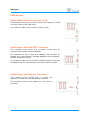
AbioCard model A and B
I/O Cards
User Manual
March 2015
AbioCard
Table of Contents
1
Features
5
2
Technical Specifications
5
3
Installation
AbioCard
Use with Raspberry Pi model A and B
Use with Raspberry Pi model A+, B+ and 2
Use with AxiCat
6
6
6
7
7
4
Interfacing
Board Overview
General-Purpose I/O Connector (K4)
Timestamp Input (K6)
Analog Inputs Connector (K5)
LED Driver Connector (K3)
LED Driver Connector (K2)
8
8
9
9
10
10
11
5
I2C Bus
Slave Addresses
Bus Speed
Real-time Clock
8-bit I/O Expander
Analog-to-Digital Converter
Model A - LED Driver
Model B - LED Driver
12
12
12
12
12
12
12
13
6
Software
Software Revision
Overview
Accessing I2C from Software
AxiCat
Direct I/O
i2c-dev Interface
Revision of your Raspberry Pi Computer
Program abiocardtime
Executable
Command Line
Example Invocations of the Program
Program abiocardserver
Network Mode
Standard Input and Output Mode
14
14
14
14
14
14
15
15
16
16
16
17
18
18
18
2
User Manual
AbioCard
Executable
Command Line
Example Invocations of the Program
Protocol
Program abiocardgui
User Interface
Command Line
Module rpidetect
API
Source
Module abiocard
Hardware Configuration
API
Distribution Packages
Package abiocard
Package abiocardgui
Installation
Package abiocard
Package abiocardgui
Software License
Package abiocard
Program abiocardgui
18
19
20
21
27
28
33
34
34
34
35
35
36
39
39
39
39
39
39
40
40
40
7
Application Examples
8-bit I/O Expander
Basic Input
Optically Isolated Input
Basic LED Drive Output
Output with MOSFET Transistor
Output with Bipolar Transistor
Optically Isolated Output (low side switch)
Optically Isolated Output (high side switch)
Outputs with ULN2803 Driver
LED driver
Basic PWM Output for Driving a LED
PWM Output with MOSFET Transistor
PWM Output with Bipolar Transistor
PWM Outputs with ULN2803 Driver
41
41
41
41
41
42
42
42
43
43
44
44
44
44
45
8
Legal Information
Disclaimer
Trademarks
46
46
46
9
Contact Information
46
User Manual
3
AbioCard
Revision History
Date
Authors
Description
2012-08-20 Peter S'heeren
Initial release.
2012-09-09 Peter S'heeren
Updated for new revision 2 of Raspberry Pi.
Second release.
2012-09-10 Peter S'heeren
Updated for latest software.
Third release.
2012-09-17 Peter S'heeren
Fourth release.
2012-10-21 Peter S'heeren
Updated for model A and model B of the AbioCard.
Updated for latest software.
Fifth release.
2012-12-14 Peter S'heeren
Updated for latest software.
Sixth release.
2013-01-28 Peter S'heeren
Updated for latest software (issued 2013-01-26).
Updated for i2c-dev support.
Seventh release.
2013-09-17 Peter S'heeren
Updated for latest software (issued 2013-09-17).
Eighth release.
2014-07-11 Peter S'heeren
Updated for latest software (issued 2014-07-07).
Added support for AxiCat.
Ninth release.
2015-03-02 Peter S'heeren
Updated for latest software (issued 2015-02-28).
Added support for Raspberry Pi model 2.
Tenth release.
4
User Manual
AbioCard
1 Features
▪
Battery backed up real-time clock and
calendar with integrated temperature
compensated crystal oscillator and a
32.768 kHz quartz crystal.
▪
8 general-purpose quasi-bidirectional
I/O lines, 5 V levels.
▪
Model A - 16 output channels providing
8-bit pulse-width modulation (PWM) at
97 kHz with LED drive capability, 10 mA
source, 25 mA sink, 5 V levels.
▪
Model B - 16 output channels providing
12-bit pulse-width modulation (PWM)
output channels at about 40 to 1000 Hz
with LED drive capability, 10 mA source, 25 mA sink, 5 V levels.
▪
Low-power, 12-bit, 8-channel analog-to-digital converter chip featuring internal
track/hold, voltage reference, and clock.
▪
Polyfuse on the 5V line for preventing damage to the computer.
▪
Compact footprint due to the use of SMD components.
▪
Free software.
Applications include:
▪
Home automation (domotics).
▪
Industrial automation.
▪
Multimedia (ambient effect, audio spectrum display, ...).
▪
RGB LED control.
▪
Educational purposes.
▪
Model B - Motor and servo control.
2 Technical Specifications
Dimensions
55 mm x 40 mm x 18 mm (W x D x H)
Weight
16 g (without battery)
RTC backup power
10 years
User Manual
5
AbioCard
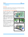
3 Installation
AbioCard
First of all, place a CR2032 battery in the battery holder on the backside of the AbioCard.
Note that when no battery is present, the AbioCard will work except the real-time clock
won't keep the time when the system is powered down.
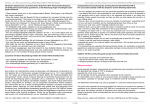
Use with Raspberry Pi model A and B
The AbioCard has a 2x13 pin female
header that fits perfectly on your
Raspberry Pi computer. Be sure you
connect the AbioCard in such a way it
hovers over the computer as shown in the
picture to the right.
A dedicated enclosure for the combo is
available. If you prefer not to use the
dedicated enclosure, it's recommended to
mount the spacer that came with the
AbioCard between the AbioCard and the
computer. The AbioCard provides a
mounting hole for this purpose. Use the
included nylon washers to adjust for
optimal height.
Whether you use the enclosure or the
spacer, it's that the AbioCard's backside
can't touch the computer directly. When
mounting,
you've
to
prevent
the
AbioCard's lithium battery from touching
components on the computer PCB.
An enclosure specifically designed for the
combo is available.
The enclosure comes with holes on top
that allow you to connect external
hardware to the 2x5 pin female headers.
You can use jumper wires and ribbon cable
connectors for this purpose.
6
User Manual
AbioCard
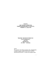
Use with Raspberry Pi model A+, B+ and 2
The AbioCard fits on Raspberry Pi model
A+, Raspberry Pi model B+, and Raspberry
Pi model 2.
The 40-pin header on these computers is
an extension of the 26-pin header that's
found on model A and model B. Be sure
the AbioCard is mounted as shown in the
picture to the right.
You've to prevent the AbioCard's lithium
battery from touching components on the
computer PCB.
Note that you can't mount the spacer that
came with the AbioCard; there's a
component on the computer that prevents successful positioning of the spacer. A good
way to keep the AbioCard and computer apart is sticking one or two bumpers between
the bottom of the AbioCard and the top of the computer's HDMI connector.
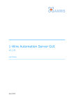
Use with AxiCat
With the help of the AxiCat, you can connect an AbioCard model A or B to any computer
that's capable of running the AbioCard software.
Make sure the jumper (JP1) is set to 3.3 V operation as shown in the picture
above!
It's important that the AbioCard's backside can't touch the AxiCat directly. Mount the
spacer that came with the AbioCard between the AbioCard and the AxiCat. Both the
AbioCard and the AxiCat provide a mounting hole for this purpose. Use the included
nylon washers to adjust for optimal height.
User Manual
7
AbioCard
4 Interfacing
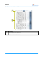
Board Overview
1
2
5
3
6
7
4
Mark
Label
Description
1
K4
PCF8574 general-purpose I/O connector
2
K6
PCF2129A timestamp input
3
K5
MAX11614 analog inputs connector
4
K3
Model A PCA9635 LED driver pins LED8-LED15 connector
Model B PCA9685 LED driver pins LED8-LED15 connector
5
K2
Model A PCA9635 LED driver pins LED0-LED7 connector
Model B PCA9685 LED driver pins LED0-LED7 connector
6
7
8
RTC backup power battery, 3 V type CR2032
K1
I/O female connector
User Manual
AbioCard
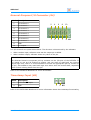
General-Purpose I/O Connector (K4)
Mark
Description
1
I/O channel 0
2
I/O channel 1
3
I/O channel 2
4
I/O channel 3
5
I/O channel 4
6
I/O channel 5
7
I/O channel 6
8
I/O channel 7
9
GND
10
2
4
6
8
10
1
3
5
7
9 K4
5 V output
The I/O channels are quasi-bidirectional. The direction is determined by the software:
▪
When used as input, software must set the output pin to HIGH.
▪
When used as output, software writes any value to the pin.
IMPORTANT!
The AbioCard doesn't incorporate pull-up resistors on the I/O pins of the PCF8574. If
you intend to use an I/O channel as output, and you want to read back the current
output logic level, then it is recommended to connect an appropriate pull-up resistor to
the pin, else software may read back logic zero rather than the actual state, especially
when current is being drawn from the pin.
Refer to the PCF8574 datasheet for more information.
Timestamp Input (K6)
Mark
Description
1
PCF2129A TS input
2
GND
1
2 K6
Refer to the PCF2129A datasheet for more information about the timestamp functionality.
User Manual
9
AbioCard
Analog Inputs Connector (K5)
Mark
Description
1
Analog input 0
2
Analog input 1
3
Analog input 2
4
Analog input 3
5
Analog input 4
6
Analog input 5
7
Analog input 6
8
Analog input 7
9
GND
10
2
4
6
8
10
1
3
5
7
9
K5
5 V output
Connector K5 exposes the 8 analog input pins of the MAX11614. This chip offers a variety
of settings for using the analog inputs. Refer to the MAX11614 datasheet for more
information.
LED Driver Connector (K3)
Mark
Description
1
LED driver pin LED8
2
LED driver pin LED9
3
LED driver pin LED10
4
LED driver pin LED11
5
LED driver pin LED12
6
LED driver pin LED13
7
LED driver pin LED14
8
LED driver pin LED15
9
GND
10
2
4
6
8
10
1
3
5
7
9 K3
5 V output
Connector K3 exposes the last eight LED outputs of the LED driver.
Model A - Refer to the PCA9635 datasheet for more information.
Model B - Refer to the PCA9685 datasheet for more information.
10
User Manual
AbioCard
LED Driver Connector (K2)
Mark
Description
1
LED driver pin LED0
2
LED driver pin LED1
3
LED driver pin LED2
4
LED driver pin LED3
5
LED driver pin LED4
6
LED driver pin LED5
7
LED driver pin LED6
8
LED driver pin LED7
9
GND
10
2
4
6
8
10
1
3
5
7
9 K2
5 V output
Connector K2 exposes the first eight LED outputs of the LED driver.
Model A - Refer to the PCA9635 datasheet for more information.
Model B - Refer to the PCA9685 datasheet for more information.
User Manual
11
AbioCard
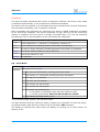
5 I2C Bus
Slave Addresses
The I2C bus on the AbioCard interconnects your AxiCat or Raspberry Pi computer with a
set of I2C slave devices. Each slave device responds to one or more I2C addresses. The
slave addresses are:
Address
Slave Device
1010001b PCF2129A real-time clock
0100111b PCF8574 8-bit I/O expander
0110011b MAX11614 analog-to-digital converter
0001000b Model A PCA9635 LED driver
1001000b Model B PCA9685 LED driver
1110000b PCA9635/PCA9685 all devices "LED All Call" address
0000011b PCA9635/PCA9685 all devices SWRST (software reset)
Bus Speed
The AbioCard supports a maximum bus speed of 100 kHz.
Real-time Clock
The PCF2129A is a real-time clock and calendar with an integrated temperature
compensated crystal oscillator and a 32.768 kHz quartz crystal. The PCF2129A has a
backup battery switch-over circuit, a programmable watchdog function, a timestamp
function, and many other features.
The board has a holder for a CR2032 battery that functions as backup power for the
PCF2129A.
8-bit I/O Expander
The PCF8574 is an 8-bit I/O expander. The outputs feature a high current drive capable
of directly driving LEDs.
The I/O channels are quasi-bidirectional. Refer to the PCF8574 datasheet for more
information.
Analog-to-Digital Converter
The MAX11614EEE+ is a low-power, 12-bit, 8-channel analog-to-digital converter chip
featuring internal track/hold (T/H), voltage reference, and clock.
Model A - LED Driver
The PCA9635 is an 8-bit PWM LED driver optimized for red/green/blue/amber (RGBA)
color mixing applications.
12
User Manual
AbioCard
The PCA9635 uses a frequency of 97 kHz for PWM control. An additional frequency of 190
Hz and a adjustable frequency of about 24 Hz to 0.01 Hz provide dimming and blinking
features.
Model B - LED Driver
The PCA9685 is a PWM LED driver optimized for red/green/blue/amber (RGBA) color
mixing applications.
The PCA9685 uses a frequency of about 40 to 1000 Hz for PWM control enabling it to
drive motors and servos.
The on and off times of the PWM output signal can be programmed for each channel
individually. This design aids in minimizing current surges.
User Manual
13
AbioCard
6 Software
Software Revision
This document corresponds with the AbioCard software issued 2015-02-28.
Overview
The AbioCard comes with a number of software programs that run on Linux and Windows
operating systems.
This document describes commands entered at the command prompt of Linux. When
entering a command at the prompt of your personal log in, the document uses the $
notation. For example:
$ sudo ./abiocardtime -p
A command entered at the prompt of the root log in is written with the # notation. For
example:
# ./abiocardtime -u
This document describes commands entered at the command prompt of Windows with
the > notation. For example:
> abiocardserver.exe -p 5678 -axicat \\.\COM4
Accessing I2C from Software
Software has several ways of accessing the I2C-based AbioCard on your hardware:
▪
Direct I/O (available on Raspberry Pi computers running Linux).
▪
Using the Linux i2c-dev interface (available on Linux systems).
▪
Using the AxiCat board (Linux and Windows systems).
AxiCat
The AxiCat board is USB-based. The board enables you to connect your AbioCard to a
variety of computer systems that run Linux or Windows.
The AxiCat incorporates an FT245 chip and is enumerated as a USB-to-serial adapter. The
operating system assigns a serial path to the AxiCat which you pass as an argument to
the software.
AxiCat I/O may or may not require root privileges in Linux. It depends on the
permissions the system forces on serial paths. If you're not sure, you're advised to run
the software as root.
Direct I/O
Direct I/O means the programs that run on your Raspberry Pi computer directly
communicate with the AbioCard from user-mode using the first serial controller (BSC0)
or the second serial controller (BSC1) on the BCM2835/2836 application processor.
14
User Manual
AbioCard
Obviously using direct I/O is appropriate when no I2C driver is loaded, or at least the
BSC that connects to the AbioCard is not under control of any I2C driver.
Direct I/O requires root privileges.
IMPORTANT!
Do not force the programs to use direct I/O if I2C drivers are present. Doing so may
disrupt the proper working of the I2C drivers and subsequently hang or crash the
operating system.
i2c-dev Interface
I2C driver support in Linux includes a driver named i2c-dev. This driver offers a file
interface to the I2C adapters from user-mode through files in the /dev directory. These
files are named /dev/i2c-<n> where <n> is a number starting from zero:
▪
/dev/i2c-0 – i2c-dev interface for BSC0.
▪
/dev/i2c-1 – i2c-dev interface for BSC1.
Normally access to these files requires root privileges.
Whether or not the i2c-dev interface is present depends on various settings and
attributes, including the version of the Linux kernel, presence of the device tree feature,
and blacklisting of drivers. Please refer to the Raspberry Pi documentation for more
information.
Revision of your Raspberry Pi Computer
There are several revisions of the computer. The GPIO pins are not compatible between
these revisions. Although the incompatibility doesn't affect the AbioCard hardware, it
does affect the software as follows:
▪
Older revisions: The GPIO header pins 3 and 5 are wired to BSC0.
▪
Newer revisions: The GPIO header pins 3 and 5 are wired to BSC1.
Older revisions only include Raspberry Pi model A and model B. Model A+, model B+ and
model 2 are always newer revisions.
Please refer to the Raspberry Pi documentation for more information.
The programs abiocardtime and abiocardserver auto-detect the revision of the
computer and as such the BSC to use. They also provide command line parameters for
overruling the detected BSC.
Program abiocardgui provides arrows for selecting the BSC.
If you're not sure about the revision and which BSC is wired to GPIO header pins 3 and
5, you can proceed as follows. Install the abiocardgui package on your Raspberry Pi
with the AbioCard installed. Run the program abiocardgui. Depending on the I2C
interface, proceed with one of the following steps:
▪
Direct I/O: Connect with either BSC until connection succeeds. The selected BSC then
is the one wired to GPIO header pins 3 and 5.
▪
i2c-dev interface: Select i2c-dev. Enter /dev/i2c-<n> where <n> is 0 or 1 and try
connecting. If the connection is successful the number indicates the BSC.
User Manual
15
AbioCard
Program abiocardtime
This program runs on Linux systems. It only runs for a very short time. Its main purpose
is to read the current date and time from the RTC on the AbioCard and update the
operating system's software clock accordingly.
The program can't set the operating system's software clock when the real-time clock
reports the power-up detected state. You'll need to set the actual date and time in the
real-time clock first. You can use the abiocardgui program for this purpose or run the
abiocardtime program at the command prompt with the "-s" parameter.
The program is expected to run once during Linux startup. Once Linux is running, it's
recommended to execute the program periodically in order to keep the operating
system's software clock in line with the more accurate real-time clock on the AbioCard.
Executable
Since the program can run on various Linux systems, you've to build the executable for
your specific Linux installation.
To build the program in Linux:
$ make -f abiocardtime.mk
To clean up the intermediate build files:
$ make -f abiocardtime.mk clean
If you follow the installation procedure for the abiocard package, the installation script
will build the program automatically (unless the executable already exists) and add it to
the cron table of the root user.
Command Line
Parameter
Description
-s STRING
Set system date and time from the RTC.
Example STRING: "2014-07-07 12:18:48".
-u
Update the system time using the RTC.
-p
Poll the RTC and print.
-axicat PATH Select the AxiCat with the given serial path as the interface.
Example PATH: /dev/ttyUSB0
-bsc n
This parameter forces the use of direct I/O. Value n=0..1 decimal. The
value selects the BSC.
-dev FILE
This parameter forces the use of the i2c-dev interface.
Example FILE: /dev/i2c-0
If no interface is specified, the program assumes it's running on a Raspberry Pi computer
and automatically tries to detect the I/O interface to use and the target BSC. If this is not
the intended behavior, use the -axicat, -bsc or -dev parameter to overrule the
detection.
When multiple of the following commands are specified, they're executed in this order:
16
User Manual
AbioCard
-s STRING ► -u ► -p
Example Invocations of the Program
Use automatic detection of the I/O interface on a Raspberry Pi computer and update the
system time using the RTC:
# ./abiocardtime -u
Deploy an AxiCat with AbioCard in Linux, update the system time using the RTC:
$ ./abiocardtime -u -axicat /dev/ttyUSB0
Set the date and time in the RTC of an AbioCard plugged into an AxiCat:
$ ./abiocardtime -s "2014-07-07 12:18:48" -axicat /dev/ttyUSB0
User Manual
17
AbioCard
Program abiocardserver
This server program runs on Linux and Windows systems. The server supports the
hardware configuration implemented by the abiocard module.
The server offers two modes of communication with the AbioCard:
▪
Network mode: a socket interface enables communication over the network.
▪
Standard input and output mode: another process communicates with the AbioCard.
The server uses a simple protocol for accepting commands and generating responses in
human-readable format using the ASCII character set. There's a timeout on incoming
characters, specified in seconds. When the server doesn't receive any character for the
specified time, it'll close the connection with the client. The timeout is not applicable
when standard input and output are used.
Network Mode
The dearest client of the server is the abiocardgui program.
You can use a terminal program (like Putty) for sending commands manually to the
server. Be sure to specify a timeout value big enough so the server won't shut down your
connection should you type too slow. You may as well specify the maximum timeout
value for the purpose of using a terminal program.
The server program works with one AbioCard, hence it will accept one incoming socket
connection only. If you want to provide access to more than one AbioCard from the same
computer, you can run multiple instances of the server, one instance for each AbioCard.
The server is designed to run in the background. When you require the permanent
services of the program, it's recommended to execute abiocardserver during Linux
startup.
The server will only interact with the AbioCard when it has accepted an incoming
connection. As such it can safely be invoked alongside the abiocardtime program during
Linux startup without the risk of interfering with the proper execution of the
abiocardtime program.
Standard Input and Output Mode
This mode allows another running process to directly write commands to the server and
read responses back on the same system.
Typical use-cases include manually typing in and sending commands from the console,
piping files with commands to the server, and controlling the AbioCard from a scripting
language.
Executable
Linux
Since the program can run on various Linux systems, you've to build the executable for
your specific Linux installation.
To build the program:
$ make -f abiocardserver.mk
18
User Manual
AbioCard
To clean up the intermediate build files:
$ make -f abiocardserver.mk clean
If you follow the installation procedure for the abiocard package, the installation script
will build the program automatically (unless the executable already exists) and add it to
the cron table of the root user.
Windows
The executable for Windows operating systems is included in the abiocard package.
Command Line
Parameter
Description
-h
Print help.
-console
Open a console window.
Windows only.
-p n
Select network mode. The value specifies the port number the server
must listen to. Value n=1..65535 decimal.
-t n
Time-out value between two incoming characters. Value n=5..65535
decimal (seconds).
This parameter is optional. The default value is 30 seconds.
-stdio
Select standard input and output mode.
-axicat PATH Select the AxiCat with the given serial path as the interface.
Example PATH in Linux: /dev/ttyUSB0
Example PATH in Windows: \\.\COM4
-bsc n
Select the BSC. Value n=0..1 decimal. This parameter forces the use of
direct I/O and overrules the detected BSC value.
Linux only.
-dev FILE
This parameter forces the use of the i2c-dev interface.
Example FILE: /dev/i2c-0
Linux only.
Parameter -p or -stdio must be specified.
In Linux, if no interface is specified, the program assumes it's running on a Raspberry Pi
computer and automatically tries to detect the interface to use and the target BSC. If this
is not the intended behavior, use the -axicat, -bsc, -dev or -stdio parameter to
overrule the detection.
The Windows version of the program only supports the AxiCat interface.
Hint: If you want a console window, specify -console as the first parameter. Doing so will
always bring up the console even if there's an error in the command line.
User Manual
19
AbioCard
Example Invocations of the Program
Use automatic detection of interface on a Raspberry Pi computer. The server listens to
port 5678. Time-out value is set to 5 seconds. Command:
$ sudo ./abiocardserver -p 5678 -t 5
By using standard input and output, you can type commands in the shell and look at the
resulting responses:
$ sudo ./abiocardserver -stdio
HI
HI17
EW48
ER
ER48
CR
CR13091701113501
You
The
You
You
The
You
The
enter this command
program's response
enter this command
enter this command
program's response
enter this command
program's response
Send an EOF character to close the program. In Linux, press CTRL-D. In Windows, press
CTRL-Z followed by ENTER.
Instead of typing the commands in the shell, one may spawn the program from another
process and send and receive commands and responses over standard input and output
to control the AbioCard programmatically.
By using pipes, you can stream a file containing commands into the program and stream
out the results into another file:
$ sudo ./abiocardserver -stdio < commands.txt > responses.txt
Typing commands in the shell and sending them to an AbioCard with an AxiCat on a
Windows system:
> abiocardserver.exe -stdio -axicat \\.\COM10
$ sudo ./abiocardserver -stdio
CR
You enter this command
CR13091701113501
The program's response
20
User Manual
AbioCard
Protocol
The server accepts commands and returns a response if defined. The server never sends
a response autonomously, it only responds to individual commands.
The server will only respond to a command when the command was correctly formatted,
was executed successfully, and a response is defined.
Both commands and responses are composed of a string of ASCII characters concluded
by an end-of-line character. The server recognizes LF (10) and CR (13) as end-of-line
marker. A response from the server is always concluded with a LF (10).The following
formatting is used in the description of the commands and responses:
Format
Description
CR
Literal characters i.e. character 'C' followed by character 'R'.
ABC
These characters containing specific information as explained.
[ABC]
An array of these characters containing specific information as explained.
<EOL>
End-of-line marker, either LF (10) or CR (13).
<LF>
End-of-line marker LF (10).
<none>
No response.
CR – Clock Read
Command CR<EOL>
Response
CRYYMMDDhhmmsspb<LF>
YY The year, 00..99 decimal, meaning year 2000..2099.
MM The month, 01..12 decimal, meaning January..December.
DD The day, 01..31 decimal.
hh The hour, 00..23 decimal.
mm The minute, 00..59 decimal.
ss The second, 00..59 decimal.
p
The power-up detected flag:
▪ =0: No power-up detected, date and time fields are valid.
▪ =1: Power-up detected, date and time fields are invalid.
b
The battery low flag, either 0 or 1.
This command reads (“polls”) the real-time clock.
The date and time field are valid only when no power-up is detected. To clear the powerup detected state, data and time must be set by sending a CW command.
The battery is deemed low when either the battery is running out or when there's no
battery at all.
User Manual
21
AbioCard
CW – Clock Write
Command CWYYMMDDhhmmss<EOL>
YY The year, 00..99 decimal, meaning year 2000..2099.
MM The month, 01..12 decimal, meaning January..December.
DD The day, 01..31 decimal.
hh The hour, 00..23 decimal.
mm The minute, 00..59 decimal.
ss The second, 00..59 decimal.
Response
<none>
This command writes the date and time to the real-time clock.
If successful, the power-up detected state will be cleared.
ER – I/O Expander Read
Command ER<EOL>
Response
ERXX<LF>
XX 8-bit value read from the I/O expander inputs, 00..FF hexadecimal.
This command reads the state of the inputs of the I/O expander chip and responds with
the resulting value.
EW – I/O Expander Write
Command EWXX<EOL>
XX 8-bit value to write to the I/O expander outputs, 00..FF hexadecimal.
Response
<none>
This command writes the 8-bit value to the outputs of the I/O expander.
22
User Manual
AbioCard
AR – ADC Read
Command AR<EOL>
Response
ARV00V01V02V03V04V05V06V07<LF>
V00 Converted value of analog input 0, 000..FFF hexadecimal.
V01 Converted value of analog input 1, 000..FFF hexadecimal.
V02 Converted value of analog input 2, 000..FFF hexadecimal.
V03 Converted value of analog input 3, 000..FFF hexadecimal.
V04 Converted value of analog input 4, 000..FFF hexadecimal.
V05 Converted value of analog input 5, 000..FFF hexadecimal.
V06 Converted value of analog input 6, 000..FFF hexadecimal.
V07 Converted value of analog input 7, 000..FFF hexadecimal.
This command converts all eight analog inputs and responds with the values.
PR – PWM Read
Command PRSSCC<EOL>
Response
SS
Start index, 00..10 hexadecimal.
CC
Count, 01..11 hexadecimal.
PRSSCC[XX]<LF>
SS
Start index, 00..10 hexadecimal.
CC
Count, 01..11 hexadecimal.
[XX] Array of register values, 00..FF hexadecimal. The count field indicates
the number of array elements.
This command reads registers in the PCA9635 LED driver.
Indexes 0 to 15 correspond with registers PWM0 to PWM15, index 16 with register
GRPPWM in the LED driver chip.
User Manual
23
AbioCard
PW – PWM Write
Command PWSSCC[XX]<EOL>
SS
Start index, 00..10 hexadecimal.
CC
Count, 01..11 hexadecimal.
[XX] Array of register values, 00..FF hexadecimal. The count field indicates
the number of array elements.
Response
<none>
This command writes registers in the PCA9635 LED driver.
Indexes 0 to 15 correspond with registers PWM0 to PWM15, index 16 with register
GRPPWM in the LED driver chip.
QP – PWM2 Read Prescaler
Command QP<EOL>
Response
QPXX<LF>
XX 8-bit value read from the prescaler register, 00..FF hexadecimal.
This command reads the prescaler register in the PCA9685 and responds with the
resulting value.
QQ – PWM2 Write Prescaler
Command QQXX<EOL>
XX 8-bit value to write to the prescaler register, 00..FF hexadecimal.
Response
<none>
This command writes the 8-bit value to the prescaler register in the PCA9685.
Note that the PCA9685 forces the minimal value that can be written to the prescaler is 3.
So if you issue a value between 0..2, the hardware will write 3 to the prescaler register.
You can always read back the actual prescaler register value using the QP command.
24
User Manual
AbioCard
QR – PWM2 Read
Command QRSSCC<EOL>
Response
SS
Start index, 00..0F hexadecimal.
CC
Count, 01..10 hexadecimal.
QRSSCC[V000V001]<LF>
SS
Start index, 00..0F hexadecimal.
CC
Count, 01..10 hexadecimal.
[…] Array of value pairs. The count field indicates the number of pairs.
V000 Settings of the ON state of the PWM output signal, 0000..1FFF
hexadecimal. This value is composed of bit fields:
bit 15..13 Zero.
12 Always ON yes/no (1/0).
11..0 ON time (0..4095).
V001 Settings of the OFF state of the PWM output signal, 0000..1FFF
hexadecimal. This value is composed of bit fields:
bit 15..13 Zero.
12 Always OFF yes/no (1/0).
11..0 OFF time (0..4095).
This command reads the PWM registers of one or more channels in the PCA9685 LED
driver.
User Manual
25
AbioCard
QW – PWM2 Write
Command QWSSCC[V000V001]<EOL>
SS
Start index, 00..0F hexadecimal.
CC
Count, 01..10 hexadecimal.
[…] Array of value pairs. The count field indicates the number of pairs.
V000 Settings of the ON state of the PWM output signal, 0000..1FFF
hexadecimal. This value is composed of bit fields:
bit 15..13 Zero.
12 Always ON yes/no (1/0).
11..0 ON time (0..4095).
V001 Settings of the OFF state of the PWM output signal, 0000..1FFF
hexadecimal. This value is composed of bit fields:
bit 15..13 Zero.
12 Always OFF yes/no (1/0).
11..0 OFF time (0..4095).
Response
<none>
This command writes the PWM registers of one or more channels in the PCA9685 LED
driver.
Note that the “always OFF” bit overrules the “always ON” bit. When both bits are set to
one, the PCA9685 will turn off the PWM channel.
HI – Hardware Information
Command HI<EOL>
Response
HIXX<LF>
XX Hardware presence bit mask, 00..FF hexadecimal.
Bit 0: Real-time clock is present yes/no (1/0).
Bit 1: I/O expander is present yes/no (1/0).
Bit 2: Analog-to-digital converter is present yes/no (1/0).
Bit 3: PCA9635 LED driver is present yes/no (1/0).
Bit 4: PCA9685 LED driver is present yes/no (1/0).
Bit 5..7: Reserved (0).
This command queries the hardware information gathered during initialization of the
AbioCard.
QU – Quit the server
Command QU<EOL>
Response
<none>
When the server receives this command, it immediately closes the connection, shuts
down the port it's listening to, and terminates.
26
User Manual
AbioCard
Program abiocardgui
The abiocardgui program is a
graphical
front-end
application
that visualizes the state of the
AbioCard and allows the user to
interact with the AbioCard.
The program runs on a variety of
systems including Linux for x86
and ARM, and Windows 2000 and
later.
When the program runs locally on
your Raspberry Pi computer, it can
directly communicate with the
AbioCard.
You can mount the AbioCard on an
AxiCat and connect the combo to
many computer systems.
The program is capable of connecting to the abiocardserver program over a network.
This mode allows you to inspect and control the AbioCard remotely, thus from another
computer.
A nice feature of the program is the ability to work with AbioRTC and AbioWire devices.
You can use the program to get and set the date and time of the real-time clock chip.
User Manual
27
AbioCard
User Interface
The Interface Panel
2 3
4
10
8
1
5
9
6
7
Mark Description
1
Click the left arrow and right arrow to cycle through the available interfaces. The
selected interface is shown between the arrows.
2
For i2c-dev I/O, you've to enter the device path here.
3
For network I/O, you've to enter the host here. The application accepts three
representations:
▪ An IPv4 address.
▪ The word localhost. It's interpreted as IPv4 address 127.0.0.1.
▪ A domain name. Upon connection, the application will perform a DNS look up
to determine the corresponding IPv4 address.
4
For network I/O, you've to enter the port number here.
5
For use with an AxiCat, you've to enter the serial path here.
6
Click the PWM button to show the panel for the LED driver of model A.
7
Click the PWM2 button to show the panel for the LED driver of model B.
8
Click the Connect button to connect with the AbioCard.
9
Click the Disconnect button to disconnect from the AbioCard.
10
28
Status information is displayed here.
User Manual
AbioCard
The I/O Expander Panel
1
2
4
3
Mark Description
1
Click the buttons to toggle the direction of the I/O channel.
2
State of the I/O lines.
3
For I/O channels with output direction, click to toggle the output state.
4
Inverse logic checkbox. This checkbox is a visual-only control. Toggling it does
not change the state of the I/O expander chip.
User Manual
29
AbioCard
The Real-time Clock Panel
1
2
4
5
3
6
7
Mark Description
1
Click the Copy button to copy the system time to the edit fields for data and
time. The system time is displayed next to the Copy button.
2
Click the Set button to write the date and time in the edit fields to the AbioCard.
3
Click the Poll button to force a clock read command with the AbioCard. This
button is useful when the Auto-poll checkbox is unchecked.
4
The current system time.
5
These edit fields enable you to enter a date and time which you can set in the
AbioCard device using the Set button.
6
The Auto-poll checkbox let you decide whether the application automatically
polls the real-time clock.
7
The information most recently read from the real-time clock.
The Analog-to-Digital Converter Panel
1
Mark Description
1
30
The state of the analog inputs.
User Manual
AbioCard
The LED Driver Panel for model A
1
2
Mark Description
1
The state of the PWMGRP register. Slide the scrollbar to adjust the value.
2
The state of registers PWM0 to PWM15. Slide a scrollbar to adjust the value.
User Manual
31
AbioCard
The LED Driver Panel for model B
1
2
Mark Description
32
1
General settings of the LED driver.
2
The state of each output channel.
User Manual
AbioCard
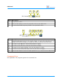
1 2 3
Mark Description
1
The prescaler value.
2
Click the Set button to write the prescaler value to the LED driver.
3
The calculated PWM frequency based on the prescaler value.
1
2 3 4 5 6
Mark Description
1
Expected PWM wave form of the output signal. You can click and drag the top
triangle and bottom triangle to change the values of ON time and OFF time.
2
The value of the ON time. Click the Set button to apply.
3
The value of the OFF time. Click the Set button to apply.
4
The state of the Always ON flag. Click the Set button to apply.
5
The state of the Always OFF flag. Click the Set button to apply.
6
Click the Set button to write the data specified in 2, 3, 4 and 5 to the LED driver.
Command Line
Not applicable. The program ignores the command line.
User Manual
33
AbioCard
Module rpidetect
A Raspberry Pi computer is built around the BCM2835 or BCM2836 application processor.
The rpidetect module is designed to detect a Raspberry Pi computer.
All programs that communicate with the AbioCard using direct I/O access the application
processor's hardware registers directly from user-mode using memory-mapped I/O.
Running these programs on a system other than a Raspberry Pi computer will lead to
unpredictable results unless they're aware of the presence or non-presence of the
expected hardware. To guarantee such problems won't occur, the programs incorporate
the rpidetect module. They will first detect the Raspberry Pi hardware before they make
any attempt to access the AbioCard.
API
Each function in the API is briefly explained. Refer to the source code for more details.
VOID
rpidetect (RPIDETECT_IO *io)
Runs the detection procedure.
If field io->chip is non-zero, the function has successfully detected a Raspberry Pi
computer and the field tells which application processor is present.
Source
Filename
Description
rpidetect.c
Implementation of the module.
rpidetect.h
Public header of the module.
34
User Manual
AbioCard
Module abiocard
The abiocard module offers an API in C for communicating with the AbioCard from your
own program.
This module can also be used for driving the real-time clock on AbioRTC and AbioWire.
Hardware Configuration
The chips on the AbioCard offer many features and configurations. To keep the software
simple, the abiocard module offers a broad subset of the AbioCard's capabilities through
its API. The programs abiocardserver and abiocardgui support the same subset.
Chip
Supported subset
Real-time clock
▪
▪
▪
Power-up detection during polling.
Low battery detection during polling.
Current time and date function, 24-hour mode only, weekday
not used.
8-bit I/O expander
▪
Not configurable.
Analog-to-digital
converter
▪
▪
▪
▪
▪
Unipolar: sampling values are 12-bit unsigned (0..4095).
Single-ended use of the analog inputs.
All 8 analog inputs are converted in one command.
Using internal clock.
Using internal voltage reference (4.096V).
Model A
LED driver
▪
▪
▪
All LED outputs programmable.
All LED groups under dimming control, no blinking.
Software handling of dimming value:
▪ When GRPPWM is 0..254, all LED group are set to mode 3.
▪ When GRPPWM is 255, all LED group are set to mode 2.
INVRT=1: Output logic state inverted.
OUTDRV=1: Totem-pole structure.
DMBLNK=0: Group control is dimming.
OCH=0: Outputs change on I2C STOP command.
OUTNE[1..0]=10b: When OE is high, LED outputs are highimpedance. Note that OE is hardwired to ground.
▪
▪
▪
▪
▪
Model B
LED driver
User Manual
▪
▪
▪
▪
▪
▪
All LED outputs programmable.
EXTCLK=0: Use the internal clock of 25 MHz.
INVRT=0: Output logic state not inverted.
OUTDRV=1: Totem-pole structure.
OCH=0: Outputs change on I2C STOP command.
OUTNE[1..0]=10b: When OE is high, LED outputs are highimpedance. Note that OE is hardwired to ground.
35
AbioCard
API
The API support the hardware configuration described in the previous chapter.
Each function in the API is briefly explained. Refer to the source code for more details.
ABIOCARD_HANDLE
abiocard_init (ABIOCARD_INIT_IO *io)
Initializes an instance of the AbioCard driver. This function performs the following tasks:
▪
It creates a context for the AbioCard driver.
▪
It probes for the presence of the various chips on the AbioCard. The software is
indiscriminate of the model of AbioCard. At least one chip must be present, else
initialization fails.
▪
It initializes the analog-to-digital converter chip, if present.
▪
It initializes the LED driver chip for AbioCard model A, if present.
▪
It initializes the LED driver chip for AbioCard model B, if present.
When the function returns a non-zero value, the initialization was successful and the
other functions can be called safely with the returned handle.
When the function returns zero, there was an error. The io->err field will contain the
error code. Note that it's allowed to call abiocard_deinit with a handle value of zero.
VOID
abiocard_deinit (ABIOCARD_HANDLE handle)
Deinitializes the instance of the AbioCard driver associated with the given handle. A
program must call this function when it's done using the module.
If handle is zero, the function does nothing.
FLAG
abiocard_is_detached (ABIOCARD_HANDLE handle)
The AbioCard driver mark the device as detached when it encounters an unrecoverable
error. This function returns the detached state.
By calling this function regularly, software can poll for the detached state. Software
usually stops using and deinitializes the AbioCard driver when it's marked as detached.
FLAG
(
abiocard_rtc_poll
ABIOCARD_HANDLE handle,
ABIOCARD_RTC_POLL_INFO *info
)
Polls the real-time clock. The results are written to the buffer pointed to by info.
Returns one when successful, zero when something went wrong.
36
User Manual
AbioCard
FLAG
(
abiocard_rtc_set_time
ABIOCARD_HANDLE handle,
ABIOCARD_RTC_TIME *time
)
Sets the given date and time in the real-time clock.
Returns one when successful, zero when something went wrong.
FLAG
abiocard_ioexp_write (ABIOCARD_HANDLE handle, U8 word)
Writes the given 8-bit value to the I/O pins of the I/O expander chip.
Returns one when successful, zero when something went wrong.
FLAG
abiocard_ioexp_read (ABIOCARD_HANDLE handle, U8 *word)
Reads the I/O pins of the I/O expander chip and writes the resulting 8-bit value at the
address pointed to by word.
Returns one when successful, zero when something went wrong.
FLAG
(
abiocard_adc_convert
ABIOCARD_HANDLE handle,
ABIOCARD_ADC_CNV_DATA *buf
)
Converts all analog inputs and stores the resulting values in the buffer pointed to by buf.
Returns one when successful, zero when something went wrong.
FLAG
(
abiocard_pwm_write_range
ABIOCARD_HANDLE handle,
U8 *buf, U8 start, U8 cnt
)
Writes a range of values to the LED driver chip on an AbioCard model A. The values are
written to indexes numbered 0 to 16. Parameter start is the first index, parameter cnt
the number of values to write. Parameter buf points to the source buffer.
Indexes 0 to 15 correspond with registers PWM0 to PWM15, index 16 with register
GRPPWM in the LED driver chip.
Returns one when successful, zero when something went wrong.
User Manual
37
AbioCard
FLAG
(
abiocard_pwm_read_range
ABIOCARD_HANDLE handle,
U8 *buf, U8 start, U8 cnt
)
Reads a range of values from the LED driver chip on an AbioCard model A. The values are
read from indexes numbered 0 to 16. See function abiocard_pwm_write_range for a
description of the meaning of the indexes.
Returns one when successful, zero when something went wrong.
FLAG
(
abiocard_pwm2_write_range
ABIOCARD_HANDLE handle,
ABIOCARD_PWM2_CH *buf, U8 start, U8 cnt
)
Writes the PWM values for one or more channels to the LED driver chip on an AbioCard
model B. The values are written to indexes numbered 0 to 15.
Returns one when successful, zero when something went wrong.
FLAG
(
abiocard_pwm2_read_range
ABIOCARD_HANDLE handle,
ABIOCARD_PWM2_CH *buf, U8 start, U8 cnt
)
Reads the PWM values for one or more channels from the LED driver chip on an AbioCard
model B. The values are read from indexes numbered 0 to 15.
Returns one when successful, zero when something went wrong.
FLAG
abiocard_pwm2_write_prescaler (ABIOCARD_HANDLE handle, U8 val)
Writes to the prescaler register of the LED driver chip on an AbioCard model B.
Returns one when successful, zero when something went wrong.
FLAG
abiocard_pwm2_read_prescaler (ABIOCARD_HANDLE handle, U8 *val)
Reads from the prescaler register of the LED driver chip on an AbioCard model B.
Returns one when successful, zero when something went wrong.
38
User Manual
AbioCard
Distribution Packages
Package abiocard
The abiocard package contains the software that is essential for working with the
AbioCard.
The package includes source text that you can use to develop your own software for the
AbioCard in Linux and Windows.
Package abiocardgui
The abiocardgui package is supplied for various operating systems.
Installation
Package abiocard
This section assumes you've connected the AbioCard to the GPIO header of a Raspberry
Pi computer.
Unpack the abiocard package in a local directory in your home directory on your
Raspberry Pi computer.
Run the install_abiocard_rpi.sh script in the context of your user account to install the
abiocard group of programs in Linux.
Be sure to run the installation script from the command line rather than the file manager.
The script will sudo and as such the system may ask for the root password.
The installation script will add three lines to the cron table of the root user:
▪
Run the abiocardtime program at reboot.
▪
Run the abiocardtime program daily.
▪
Start the abiocardserver program at reboot (port 5678, timeout 20 seconds).
The installation script will install the programs in directory /opt/abiocard.
To set the date and time of the real-time clock and your operating system, run the
following command with the correct date and time set with the -s parameter:
$ /opt/abiocard/abiocardtime -u -s "2014-06-10 14:40:55"
Package abiocardgui
Linux
Unpack the abiocardgui package in a local directory in your home directory. Be sure you
pick the distribution that corresponds with your operating system.
Run the install.sh script in the context of your user account to install the abiocardgui
program in Linux.
Be sure to run the installation script from the command line rather than the file manager.
The script runs sudo and as such the system may ask for the root password.
User Manual
39
AbioCard
The installation script will install the files in directory /opt/abiocardgui.
The installation script will add a icon on your desktop by placing a desktop file in the
Desktop directory in your home directory. This feature works only if your window
manager is compliant with the Desktop Entry Specification by the freedesktop.org
organization.
Windows
Unpack the abiocardgui package for Win32 in a local directory on your system.
Execute abiocardgui.exe to run the application. You can create a shortcut to the
executable file on your desktop.
Software License
Package abiocard
The license is stated in the source text files.
Program abiocardgui
The computer program abiocardgui is free of charge ("freeware").
It's allowed to copy or distribute the software providing that you do so with the
distribution in its entirety as described in chapter Distribution Packages. It's forbidden to
change the software or any other files that are part of the distribution.
It's forbidden to sell, rent, or profit from the distribution in its entirety or the software or
any other files that are part of the distribution.
It's allowed to spread the distribution in a packaging format different from the packaging
format provided by Axiris.
40
User Manual
AbioCard
7 Application Examples
8-bit I/O Expander
Basic Input
This is a minimalistic circuit for using an input. When the button
is unpressed, the input is internally pulled to 5 V and is read as
HIGH. When the button is pressed, the input is pulled to ground
and is read as LOW.
Software must set the I/O pin to HIGH to use it as an input.
Optically Isolated Input
In this example, the input is optically isolated from the control circuit.
Software must set the I/O pin to HIGH to use it as an input.
Basic LED Drive Output
This example circuit shows an output driving a LED. When the
output is LOW, the LED will light up. When the output is HIGH,
the LED is off.
IMPORTANT!
▪ You must choose the resistor value depending on the type of
LED and the expected light intensity.
▪ The LED mustn't draw more than 25 mA. If multiple outputs
are connected to LEDs as shown in the picture, than the
total current mustn't exceed 100 mA. See the datasheet for
more information.
User Manual
41
AbioCard
Output with MOSFET Transistor
This example circuit shows how to switch a load using an
enhancement-mode N-channel MOSFET.
It's important to use a logic-level MOSFET that switches on
reliably at 5 V gate voltage. Example MOSFETs include
2N7000, IRL520, IRFD220, BTS141.
The maximum load current and load voltage depend on the
type of MOSFET. For inductive loads, it's recommended to
add a clamp diode as depicted.
Output with Bipolar Transistor
This example circuit shows how to switch a load
using an NPN bipolar transistor. You can replace
the NPN transistor with a NPN Darlington
transistor to increase the current amplification.
The maximum load current and load voltage
depend on the type of transistor. For inductive
loads, it's recommended to add a clamp diode as
depicted.
The maximum current sourced by the I/O
expander chip is 100 µA. It's recommended to
add an additional pull-up resistor to increase the
base current through the transistor. The pull-up
resister also guarantees the I/O expander
correctly reads back a HIGH level when software
sets the output HIGH.
The set-up with the MOSFET is recommended over this example circuit.
Optically Isolated Output (low side switch)
This example shows an optically isolated output
(low side switch).
The optocoupler used in this example is able to
switch 125 mA maximum at 300 V maximum.
42
User Manual
AbioCard
Optically Isolated Output (high side switch)
This example shows an optically isolated output (high side switch).
Outputs with ULN2803 Driver
In this example, all eight output are connected to a ULN2803 driver.
The I/O expander chip can only source 100 µA per output. The pull-up resistors are
required to reliably drive the inputs on the ULN2803.
User Manual
43
AbioCard
LED driver
Basic PWM Output for Driving a LED
This example circuit shows how to control the intensity of a LED
using an output of the LED driver.
The maximum LED current mustn't exceed 10 mA.
PWM Output with MOSFET Transistor
This example circuit shows how to switch a load using an
enhancement-mode N-channel MOSFET.
It's important to use a logic-level MOSFET that switches on
reliably at 5 V gate voltage. Example MOSFETs include 2N7000,
IRL520, IRFD220, BTS141.
The maximum load current and load voltage depend on the type
of MOSFET. It's not recommended to connect inductive loads.
PWM Output with Bipolar Transistor
This example circuit shows how to control the
intensity of a LED using an NPN bipolar transistor.
The maximum load current depends on the type of
transistor.
44
User Manual
AbioCard
PWM Outputs with ULN2803 Driver
In this example, all eight outputs are connected to a ULN2803 driver.
Since the LED driver chip can source enough current to drive the ULN2803, pull-up
resistors are not required.
User Manual
45
AbioCard
8 Legal Information
Disclaimer
Axiris products are not designed, authorized or warranted to be suitable for use in space,
nautical, space, military, medical, life-critical or safety-critical devices or equipment.
Axiris products are not designed, authorized or warranted to be suitable for use in
applications where failure or malfunction of an Axiris product can result in personal
injury, death, property damage or environmental damage.
Axiris accepts no liability for inclusion or use of Axiris products in such applications and
such inclusion or use is at the customer's own risk. Should the customer use Axiris
products for such application, the customer shall indemnify and hold Axiris harmless
against all claims and damages.
Trademarks
“Raspberry Pi” is a trademark of the Raspberry Pi Foundation.
All product names, brands, and trademarks mentioned in this document are the property
of their respective owners.
9 Contact Information
Official website: http://www.axiris.eu/
46
User Manual