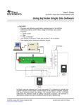
1
Mobile Power Station Final Report Project Team: Brad Jensen William Klema Nathan Schares Faculty Advisor: Dr. Ayman Fayed Client: PowerFilm, Inc. Project ID: sddec1013 12/6/2010 Iowa State University College of Engineering 1 Table of Contents 1. Introduction Material ................................................................................................................................... 1 1.1 Executive Summary ................................................................................................................................ 1 1.2 Acknowledgements ................................................................................................................................. 1 1.3 Problem Statement ................................................................................................................................. 1 1.4 Potential solution .................................................................................................................................... 2 1.5 Operating Environment ......................................................................................................................... 2 1.6 Intended Users ........................................................................................................................................ 2 1.7 Intended Uses .......................................................................................................................................... 2 1.9 Market Survey .......................................................................................................................................... 2 1.10 Intellectual Property and Legal Considerations................................................................................ 3 2. Approach ....................................................................................................................................................... 4 2.1 Concept Sketch ....................................................................................................................................... 4 2.2 System Block Diagram ........................................................................................................................... 4 2.3 Functional Requirements ....................................................................................................................... 5 2.4 Non-functional Requirements .............................................................................................................. 5 2.5 Assumptions and Limitations ............................................................................................................... 5 2.6 Deliverables.............................................................................................................................................. 6 2.7 Safety Considerations ............................................................................................................................. 6 3 Design, Implementation & Testing.............................................................................................................. 7 3.1 Design ....................................................................................................................................................... 7 3.1.1 Power Inputs .................................................................................................................................... 7 3.1.2 MPPT ................................................................................................................................................ 7 3.1.2.1 Li-ion Charging Cycle .................................................................................................................. 9 3.1.3 Microprocessor ..............................................................................................................................10 3.1.3.1 VCC and VSS..............................................................................................................................10 3.1.3.2 Voltage Senses ............................................................................................................................11 3.1.3.3 Low-side Current Sense ............................................................................................................12 3.1.3.4 High-side Current Sense ...........................................................................................................13 3.1.3.5 UART Output ............................................................................................................................14 3.1.4 Charging Circuitry .........................................................................................................................14 3.1.5 Batteries ..........................................................................................................................................15 3.1.6 Buck Converter..............................................................................................................................15 3.2 Implementation .....................................................................................................................................17 3.2.1 Initial Buck Converter ..................................................................................................................17 3.2.2 Configuring Microprocessor to Control Buck Converter .......................................................17 3.2.3 Printed Circuit Board ....................................................................................................................19 3.3 Testing ....................................................................................................................................................21 3.1 PCB Tests ..........................................................................................................................................21 3.2 Secondary Li-Ion Protection Testing ............................................................................................21 3.3 GUI Interface....................................................................................................................................22 3.4 Evaluation ..............................................................................................................................................23 4 Resource Requirements ...............................................................................................................................24 4.1 Team Utilization....................................................................................................................................24 4.2 Material list and estimates ....................................................................................................................26 4.3 Human Resource Estimates ................................................................................................................26 4.4 Project Schedule ....................................................................................................................................27 4.5 Deliverables............................................................................................................................................27 5 Project Team Information...........................................................................................................................28 6. Closing Summary ........................................................................................................................................29 References .........................................................................................................................................................30 Appendix I – Microprocessor Code .............................................................................................................31 Appendix II – PCB Sensor Calibration Graphs ..........................................................................................40 Appendix III – Schematic and PCB Layout ................................................................................................43 Appendix IV – User Manual ..........................................................................................................................47 Table of Figures Figure 1: MPS Concept Sketch ........................................................................................................................ 4 Figure 2: MPS Block Diagram ......................................................................................................................... 4 Figure 3: Current vs. Voltage Curve with Maximum Power Point [1] ....................................................... 7 Figure 4: MPPT Perturbation and Observation Method [7] ....................................................................... 8 Figure 5: Li-ion Charging Cycle ....................................................................................................................... 9 Figure 6: Microprocessor Schematic .............................................................................................................10 Figure 7: Voltage Sense Circuit ......................................................................................................................11 Figure 8: Low-side Current Sense Circuit ....................................................................................................12 Figure 9: High-side Current Sense Circuit ...................................................................................................13 Figure 10: TTL/RS-232 Driver .....................................................................................................................14 Figure 11: Buck Converter Schematic ..........................................................................................................15 Figure 12: Large Transients observed at output of breadboard circuit ...................................................18 Figure 13: Prototype PCB...............................................................................................................................19 Figure 14: Populated PCB Rev. 1 ..................................................................................................................20 Figure 15: Populated PCB Rev. 2 ..................................................................................................................20 Figure 16: Software to Track and Monitor Cell Balancing ........................................................................21 Figure 17: MPS GUI .......................................................................................................................................22 Figure 18: Efficiency vs. PWM ......................................................................................................................23 Figure 19: Efficiency vs. Iout .........................................................................................................................23 Figure 20 - Human Resources Pie Chart ......................................................................................................26 Figure 21: Semester 2 planned schedule .......................................................................................................27 Table of Tables Table 1: Electrical Parts Cost Per Unit Estimate ........................................................................................26 1. Introduction Material 1.1 Executive Summary With mobile technology surrounding every aspect of our lives, the need for mobile power— especially in remote locations–is growing. Flexible solar panels are lightweight and offer ultimate portability; however, charging mobile devices directly from flexible solar panels presents a significant problem. Most portable electronics are very sensitive to fluctuations in voltage and current and will cease charging if a fluctuation is sensed, which is likely to happen with a variable power source such as a solar panel. To solve this problem, our senior design team designed a Mobile Power Station (MPS) which is essentially the missing link between the flexible solar panel and mobile electronic devices. The MPS supplies a constant source of power in order to charge mobile electronics, and it charges from a solar panel or constant power source, offering maximum flexibility. Cutting edge circuitry and algorithms were used to maximize MPS efficiency. A need for the MPS was expressed by our client, PowerFilm, Inc., and will have applications in the military and commercial markets. 1.2 Acknowledgements Our group would like to recognize and thank Brad Scandrett and Frank Jeffrey of PowerFilm, Inc. for answering all of our questions in a timely manner and working with us to develop the best possible product. Their knowledge of the solar market and solar products has been essential in developing the MPS. We would also like to thank our advisor Dr. Fayed for his support in our senior design project. His industry knowledge and past experience has been a pivotal part of our design process. His insight has allowed us to break down our problems and develop efficient solutions. Texas Instruments also deserves great recognition through their help with the TI Analog Design Contest. TI graciously provided us with all the parts and evaluation modules necessary to make this project a success. Lastly, we’d like to thank Dr. Qiao, the EcPE senior design team, the Industry Review Panel, and CSG. They provide us with tools, help us utilize our resources, and challenge us to think about our problems from various aspects. Our group appreciates the help and support of everyone that works diligently to provide the best possible senior design experience. 1.3 Problem Statement As technology becomes more mobile, the power sources required to operate these devices must also become mobile. Photovoltaic solar arrays can be used to power mobile devices; however, solar array output power is non-constant and creates problems for mobile devices that require constant power. 1 Most mobile chargers require constant voltage and current, and will completely shut down in the event of a fluctuation. PowerFilm, Inc. manufactures flexible amorphous silicon solar arrays and has requested a design for a MPS that will allow users to charge and operate their mobile devices in remote locations using flexible solar arrays. The MPS must mitigate the problem of non-constant solar array output power. 1.4 Potential solution We propose to build a MPS containing lithium ion batteries to store energy gathered by PowerFilm flexible solar arrays. The MPS will store 100 watts of power, providing constant voltage and current to connected devices (loads). The lithium ion batteries serve as a buffer and mitigate voltage and current fluctuations. The MPS will implement a maximum power point tracking (MPPT) algorithm to maximize solar input power, and will contain lithium ion battery charge balancing circuitry. In addition to solar array input power, the MPS will also have the capability to charge from an AC-DC power supply; however, it will not charge from solar and AC-DC simultaneously. 1.5 Operating Environment The MPS will be used in extreme outdoor conditions, an operating temperature of -20ºC - 60ºC is expected. Given the small dimensions and weight requirements of the MPS, it will likely be carried in a backpack while charging from a flexible solar array situated on the outside of the backpack. The case should completely enclose the circuitry, except for the input and output power ports, to minimize debris entry. 1.6 Intended Users PowerFilm has indicated that the primary MPS user will be the United States military; however, PowerFilm also indicated interest in commercial sale of the MPS. The MPS was designed to provide power for an individual solder during missions in remote locations. Commercial users may include outdoor enthusiasts and people requiring power in isolated locations. 1.7 Intended Uses The MPS is intended to charge or power mobile devices such as laptops, cellular phones, iPods, and other mobile electronics. The MPS is designed to store 100 watts of power, which is intended to be enough energy to fully charge an ―average‖ laptop battery. The main function of the MPS is to take energy collected from flexible solar arrays and use that energy to power mobile devices. The MPS is not intended to power large devices such as televisions or inductive appliances. 1.9 Market Survey The MPS was designed upon the needs and specifications of PowerFilm Inc., which were determined from previous market research. The primary user of the MPS is the military, with the possibility of releasing a commercial version of the MPS. No significant additional market research was required. 2 1.10 Intellectual Property and Legal Considerations PowerFilm, Inc. and Iowa State University EcPE will have co-ownership of MPS technology including any patents. Algorithms designed for the MPPT and charge controller circuitry will be covered in assumptions. Several algorithms for exist for MPPT, but the MPS will require an adapted version of current MPPT algorithms. 3 2. Approach 2.1 Concept Sketch The complete MPS prototype will be encased in a rectangular container made out of a light weight material. Aluminum and plastic are both viable options. The exact dimensions of the case depend solely upon the dimensions of the PCB. The concept version of the MPS will be incased in a 8x8x2‖ plastic enclosure. With these dimensions, the MPS will fit comfortably into any backpack or large pocket. The concept sketch below is the MPS with all optional connectors. Figure 1: MPS Concept Sketch 2.2 System Block Diagram Figure 2: MPS Block Diagram 4 2.3 Functional Requirements FR 01 Optimized for standard solar panel input – 4A @ 15V (60W) Amorphous Silicon Panel FR 02 100W minimum Lithium-Ion battery capacity FR 03 15V DC input (with AC-DC Adapter) FR 04 12V DC output FR 05 Circuitry must be able to function in a temperature range of -20° C and 60°C FR 06 State of charge indicators FR 07 MPPT Charge controller with rating of up to 60W (4A @ 15V – Using 60W foldable on fully discharged batteries) FR 08 Charge Balancing Circuitry to keep Li-Ion Batteries balanced to prevent over or under charging FR 09 Temperature sensor for batteries with alarm LED FR 10 Achieve 80% or greater efficiency on all outputs 2.4 Non-functional Requirements NFR 01 NFR 02 NFR 03 NFR 04 NFR 05 The MPS shall be designed mainly for military soldier use The MPS should also be designed with options for commercial use The unit should have a weight of less than 5 pounds Unit should be manufactured for a cost of under $500 per unit The unit should easily fit inside a military backpack 2.5 Assumptions and Limitations Most technical assumptions and limitations are covered in the functional and non-functional requirements. Adequate senior design lab space will be provided. Adequate testing space and apparatus provided by PowerFilm, Inc. Evaluation boards for major components of the MPS (microprocessor & charging chip) are available PowerFilm, Inc. will provide solar panel and components not covered by the TI student program and senior design funding. PowerFilm, Inc. will design final the enclosure for the MPS circuitry. Our group needs only to build a prototype enclosure. Market research and requirements provided by PowerFilm, Inc. accurately represent the requirements of the MPS. The MPS will only be used as specified in intended uses and environments, as described in following sections. It will be more efficient to charge the MPS from a constant power supply if available. Technology developed by the senior design team will have co-ownership between PowerFilm, Inc. and Iowa State University EcPE. 5 2.6 Deliverables Upon completion of the project, the team will provide: Project Plan Design Document PCB – Populated and tested for functional requirements Schematic diagram and PCB files Operational manual Final report 2.7 Safety Considerations Short Circuit o Fuses will be installed on the DC outputs to limit the output current to protect against electrical shorts Li-ion batteries o Batteries will be temperature monitored to keep batteries above -30°C and below 100°C to assure battery safety o Battery voltage should never exceed the limits of 2.0V lower limit and 4.2V upper limit o Current limits will be placed on the battery to assure that its charging or discharging rate never exceeds 2C Note: Many Li-ion batteries can be charged and discharged at rates on the order of 10-20C, but for extended battery life and general cell stability, we will limit our outputs to 2C. o Charge time limited as secondary over charging protection 6 3 Design, Implementation & Testing 3.1 Design 3.1.1 Power Inputs There are two power source inputs to the MPS: solar panel source, 15V AC/DC wall-wart adapter. The solar panel source is controlled by the MPPT algorithm to obtain maximum power transfer from the solar panel. The 120VAC source is converted to 15VDC by an external AC/DC converter. The solar source is of great focus in this project, as it is based around MPPT. PowerFilm produces a variety of solar products that may be used with the MPS. PowerFilm has chosen to pair our MPS with its 20 Watt, 30 Watt and 60 Watt foldable solar chargers. PowerFilm also manufactures rollable solar chargers of varying wattages which also may be used. The current and voltage characteristics of these panels vary only slightly between designs and will not affect our design of the charger. Being paired with the 20, 30, and 60 watt foldable solar panels, our charger will in most cases see a solar panel charging current ranging from as low as 150mA (10% of 20W) and as much as 5 Amps. These currents were taken into account during the buck converter design and the Li-ion charging circuitry discussed later in this report. 3.1.2 MPPT The characteristics of a solar cell are determined by the irradiation from the sun and the temperature of the panel, both of which change frequently. The MPPT adjusts the voltage across the solar panel to achieve maximum power from the panel. An algorithm preformed by a microprocessor will be used to find the voltage that generates maximum power. The figure below shows a current vs. voltage curve of a typical solar panel. The smaller box inside the curve represents the maximum power output of the solar panel. Maximizing the area under the curve represents maximum power transfer from the solar array to the MPS. Figure 3: Current vs. Voltage Curve with Maximum Power Point [1] 7 MPPT is one of the key features of the MPS. We have chosen the Perturbation and Observation Method (POM) to find the Maximum Power Point (MPP) of the solar panel. The POM method works by imposing a voltage on the panel, calculating the power at the imposed voltage, then incrementing of decrementing the imposed voltage (by changing the PWM of the buck-converter) based on previous power measurements. This process can also be viewed as impedance matching between the solar panel’s internal impedance and the load’s impedance. Impedance matching is a common technique used in electrical engineering to achieve maximum power being delivered to the load. The details of the POM are shown in the figure below where V(k), I(k), and p(k) ( p(k)=V(k)×I(k) ) are the voltage, current, and power measured on the solar panel and VREF is the voltage imposed on the panel. ∆V will be determined in the testing stage of our design, but will be in the range of 10’s of mV. Figure 4: MPPT Perturbation and Observation Method [7] 8 3.1.2.1 Li-ion Charging Cycle Li-ion battery charging cycle includes three phases: trickle, constant current, and constant voltage. The charging cycles must be strictly followed to prevent battery pack overcharge and fire. The MPS uses input and output voltage and current measurements to determine which charging phase the battery pack is in. The same measurements are also used for MPPT. MPPT is really only utilized during the constant current phase of charging, when the battery pack is demanding a large amount of current. Battery pack voltage is most important measurement, and takes precedence over MPPT. The MPS utilizes a DC-DC buck converter making it very easy to hold an output voltage of 12.6V across the battery pack during constant voltage phase. The plot below best demonstrates the charging cycle. Figure 5: Li-ion Charging Cycle 9 3.1.3 Microprocessor To accurately and efficiently find the MPP, two voltage measurements and one current measurement (which will actually be a voltage measurement across a current sense resistor) will need to be collected and stored within the microprocessor. The microprocessor must also generate a pulsewidth modulated (PWM) signal, which will control the buck converter and, in turn, set the voltage across the solar panel. For testing purposes, the microprocessor must be able to communicate data back to a computer. We chose TI’s MSP430 Microprocessor for our microprocessor. Specifically, we will use the MSP430F2013 because it meets the requirements of our system: 3 analog-to-digital inputs, 1 timer to produce a PWM signal, and one additional output to be used for USART communication during the development stage of the MPS. Also, the MSP430F2013 comes in a compact 14-pin package and lacks unnecessary functionality. The figure below shows how each pin on the microprocessor will be implemented into our design. Figure 6: Microprocessor Schematic 3.1.3.1 VCC and VSS The microprocessor will be indirectly powered from the solar panel. The microprocessor will share the same ground as the solar panel (VSS connects to the solar panel’s negative terminal). A 3.3V linear regulator, connected directly to the solar panel, will step down the solar panel’s voltage to 3.3V, which will power the microprocessor, multiplexor, and op-amps. When the solar panel is not generating power, the microprocessor will rest in an off state consuming no power from the MPS’s Li-ion batteries. The instance the solar panel begins to generate power; the microprocessor will turn itself on and begin to run the MPPT algorithm. 10 3.1.3.2 Voltage Senses The voltages across the solar panel and the battery/load are monitored while the MPS operates. The solar panel voltage, along with the solar panel current, is used to calculate the power generated by the solar panel. The battery/load voltage is used to determine which charging state the Li-ion batteries are in and stabilization during the constant voltage charging stage. Figure 7: Voltage Sense Circuit The voltage sense circuit consists of a simple voltage divider to step the voltage down to a level the microprocessor can read. , 11 3.1.3.3 Low-side Current Sense The current flowing through the battery and load are measured individually with low-side current sense circuits. The MPS uses the battery and load currents magnitude and direction to determine whether the battery is supplying power to the load or the buck converter is supplying power to the load. The MPS uses the battery current measurement for stabilization during the trickle charge stage of the Li-ion batteries. Figure 8: Low-side Current Sense Circuit The low-side current sense circuit transforms the current (IL) into a voltage which is amplified by the op-amp, set up in a non-inverting configuration, into a voltage the microprocessor can read. The relationship between the current (IL) and output voltage (VO) is shown in the equation below. , 12 3.1.3.4 High-side Current Sense In order to track the maximum power point, the current emitted from the solar panel needed to be measured. The only way to accomplish this is to use a high-side current sense circuit, which proved to be very difficult to implement. After trying two op-amps, we discovered an op-amp with rail-torail common-mode input capability was required because the common-mode voltage on the sense resistor is equal to op-amp’s bias voltage. We chose Linear Technology’s LT1677 precision op-amp for our design. Figure 9: High-side Current Sense Circuit The high-side current sense circuit turns the voltage across the sense resistor (RS) into an output current (IO). The output current is then converted into a voltage through RA and read by the microprocessor. The relationship between the solar current (IS) and output voltage (VO) is shown in the equation below. , 13 3.1.3.5 UART Output The MPS communicates serially using Universal Asynchronous Receiver/Transmitter (UART). The microprocessor did not come pre-programmed registers to easily communicate with a computer through a serial interface, therefore our team programmed the microprocessor to send bytes of data serially following the UART standard form of one start bit (logic low), 8 bits of data, and then two stop bits (logic high), at a Baud rate of 9600 bits/second. To communicate with a computer through an RS-232 port, our system required a TTL/RS-232 driver. This driver transforms a logic low (0V) to +10V and a logic high (+3.3V) to -10V, which applies to RS-232 standards. This transformation is done through an IC chip (MAX232) which is shown below in a schematic is shown in Figure 7 (all capacitors are 1µF). Figure 10: TTL/RS-232 Driver 3.1.4 Charging Circuitry The charging circuitry controls which power input provides the MPS with energy. Only one power input will be selected at a time and a priority system is in place to select the source. The AC source is of highest priority (i.e. if the AC source is connected, it will power the MPS), and the solar source is of lowest priority (i.e. the solar source only powers the MPS if no other power input is connected). The charging circuitry will also turn on an LED next to the power input indicating which power input is charging the MPS. The charging circuitry ensures the batteries are charged evenly and are not under or overcharged, which could lead to catastrophic battery failure or battery damage. The Charging chip used for our design is the BQ20Z70 Li-Ion charging IC made by Texas Instruments. Initially, the BQ78PL114 chip by Texas Instruments was evaluated. This was recommended by the faculty advisor, as it had been used on previous projects. It was found that the BQ78PL114 was too costly and complicated for our project and an alternative was chosen. 14 The secondary protection used in the MPS is a BQ20Z70. It is designed using TI’s Impedance Track technology which effectively tracks the impedance of each battery to balance the batteries. 3.1.5 Batteries The batteries store the energy delivered by the power inputs. They allow the MPS to supply power to the load without a power input available, which is limited by the power carrying capacity of the batteries. For this design we have chosen to use Lithium polymer batteries because of their high energy density and low profile design. Lithium polymer batteries are also capable of delivering much higher currents than lithium-ion which is important for possible high current loads especially through the AC output. The batteries will be High Rate Lithium Polymer batteries with a nominal voltage of 3.7 volts per cell at 8 Amp hours per cell. We will use 3 batteries in series to provide a total internal nominal battery voltage of 11.1 Volts (12.6 Fully Charged). 3.1.6 Buck Converter Our buck converter design utilizes N-FETs (N-Channel MOSFETS) in a two-phase configuration run by a MOSFET driver chip (IR 2104). This chip uses a charge pump to achieve the high voltages needed to switch the N-MOSFET. The driver chip is capable of accepting a PWM input from the Microprocessor and switches the MOSFETs accordingly. The Microprocessor can also control the operation of the buck converter using the ―Shutdown‖ pin on the driver chip. This is useful in situations that may become unstable, in which the microprocessor can essentially shut down the entire system. Figure 11: Buck Converter Schematic 15 To maximize efficiency we used the following equations to calculate ripple current and ripple voltage. Ripple Current: Ripple Voltage: In research on the type of solar panels that would be provided or packaged with our system, we needed to choose a ripple current that would leave our charger in Constant Current Mode (CCM) for almost all charging situations. Our design requires the converter to operate in CCM and not in Discontinuous Current Mode (DCM) because of the losses that our system would see during DCM mode. For this system, a design was chosen with a current ripple of less than 10% of our full charging current (load current). For a current ripple of less than 500mA, we found the closest popular inductor value to be 47uH. Therefore, the ripple current equation with the values is the following; Using this ripple current, we can then calculate the output voltage ripple. We wanted to minimize our output ripple voltage to assure that there could be no inaccurate readings from the voltage feedback. For this, an output ripple voltage of 2-3mV was desired without the ESR considerations. A common 220uF capacitor size was chosen to provide the desired voltage ripple. With these values chosen and optimized for our design we assure that we can provide maximum charging efficiency. Other efficiency considerations in the design include the input N-FET to the buck converter acting as a diode to prevent feedback current when no load is present. 16 3.2 Implementation 3.2.1 Initial Buck Converter The initial design of the buck converter was implemented in the latter part or Senior Design I. Using sample parts and a breadboard, the buck converter was built. This tested the concept that our two phase NFET design would work as a buck converter. Using a function generator to supply the PWM signal and a power supply for both 3.3 and 15 volts, it was confirmed that the design would work as a buck converter. Duty cycle was adjusted to observe how output voltage was affected. With the buck converter working, soon we would be able to merge the microprocessor with the buck converter 3.2.2 Configuring Microprocessor to Control Buck Converter With both main components of the MPS completed in implementation, the next step was to implement them into an entire system. This consisted of merging all the components onto one breadboard with a shared ground. Initial testing went fairly smoothly with a few bugs in the analog and digital conversions. We found that too much time was spent in the Interrupts of the microprocessor. This caused the PWM to periodically shut down, and thus shutting down our system. A MUX had to be implemented into the circuit to handle the number of measurements that had to be made. Initially, there was a problem with our output voltage dropping out at high duty cycle but after consulting with our advisor we learned that because of the limitations of the MOSFET switching times, there was a ceiling on our maximum duty cycle. More testing was conducted and an upper limit of 93% duty cycle. With everything implemented and running on a single breadboard, more extensive testing was conducted. Using an oscilloscope our group observed large transients (as high as 1 Volt p-p) at the output of our buck converter. These transients occurred at the switching point of the MOSFET controlled by the PWM signal. 17 Figure 12: Large Transients observed at output of breadboard circuit The transients had a proportional effect with current, i.e. as current increased, so did the magnitude of the voltage transient. Many weeks were spent on this problem because the importance of a fixed voltage for the lithium-ion batteries. Many modifications were made which included slowing the switch-ON of the MOSFET using snubber networks and applying extra filters to the high side MOSFET drain. A lower value inductor was used to attempt to essentially slow down the switching. During this stage, our group learned a great deal from research and our advisor about the many nonidealities of MOSFETs and our buck converter design. It was decided that the majority of the disturbance was due to the parasitic inductances and ESR (Equivalent Series Resistance) of the components and the breadboard. A combination of the described remedies was used to lower this transient to around 200mV. During the month that was spent on this problem, our team also experienced difficulty with getting accurate voltage and current measurements. The voltage measurements were slightly inaccurate and floating, however our current measurements did not seem steady at all. We were not sure where this was coming from but our initial assumption was that it might be caused by the transients that we were seeing. After discussing it with our faculty advisor and doing some testing, we discovered that we were having a differential grounding issue. We attempted to connect all of our grounds in a star connection to cut down on this differential. The method helped slightly, however the problem still persisted. It was also found that the breadboard created a large resistance which was affecting our readings as well After a month of debugging on the breadboard we decided to finally implement our design onto a PCB. Our hope was that both the transients and the current measurements would be improved with a PCB design with a common ground plane and short traces. 18 3.2.3 Printed Circuit Board In order to alleviate the voltage transients seen by the breadboard circuit, a PCB was designed. This design incorporated many of the design strategies that were learned through the process. Most important of which was the common ground plane with a star connection for the grounds. The PCB schematic and board were made using Eagle CADsoft design software as per PowerFilm’s suggestion and request. The design and layout was performed by Brad Jensen. There were two revision of the PCB. The first PCB was a development PCB and didn’t contain a solder mask, making modifications easy. We also discovered that we had selected the wrong differential amplifier for the high-side current sense. The amplifier we selected had an insufficient common-mode voltage input range. We selected and tested a new differential amplifier with a railto-rail common–mode voltage input, which effectively met out requirements. There were a few small modifications that were implemented into PCB rev. 2 including: different high-side current sense differential amplifier, Zener diode protection, header pin consolidation, and a solder mask. Figure 13: Prototype PCB The PCB measured 3.7‖ x 2‖ and contained 39 components including resistors and capacitors. The prototype used two connectors for USART communication and for programming the microprocessor. 19 Figure 14: Populated PCB Rev. 1 Figure 15: Populated PCB Rev. 2 20 3.3 Testing 3.1 PCB Tests With the changes made onto a PCB, the entire system could be tested as a whole. The PCB was tested with a table power supply. Testing included measuring both Voltage and Current of the input and output using a resistive load. This information allowed for calibration of the voltage sensing, current sensing and overall efficiency of the system. Next the resistive load was switched to a lead acid battery. The lead acid battery was used to test the charging algorithms. The lead acid battery is much safer to charger without any secondary protection. We observed a normal charging algorithm, however we did learn that at least in the case of the lead acid battery, the voltage sensing was slightly less accurate during charging. For this we decided that an averaging method was to be used inside the microprocessor to give more accurate readings. 3.2 Secondary Li-Ion Protection Testing The safe charging of the li-ion batteries is definitely one of the most important parts of this project. The algorithm that is used in our project is supposed to safely charge the lithium ion batteries. As a practice in redundancy, a secondary protection/charge monitor is implemented on the output end of the buck converter. This charge monitor also needed to balance the series pack of batteries during the charging cycle. Multiple charge cycles were run on the Li-Ion battery pack to test its performance. The evaluation board came with a software program that also helped in monitoring the battery characteristics as it charged. The BQ20Z70 worked great for this application and will be recommended to PowerFilm for future applications Figure 16: Software to Track and Monitor Cell Balancing 21 3.3 GUI Interface A GUI interface was developed using ―Processing,‖ a freeware Java GUI development program. The MPS GUI allowed us to quickly view and interpret the serial data being transmitted by the MPS430. Data such as input voltage, input current, battery voltage, battery current, load current, and duty cycle allowed us to check the charging algorithm. In addition to viewing data, the GUI also saved the data in CSV files that was easily imported to excel. Utilizing macros in Excel, we setup a calibration program to take the CSV file and turn the serial data from the MPS430 into readable voltage and current values. The GUI also served as a great demonstration tool. Charging Li-ion batteries takes several hours, but users were able to see a dynamic plot of data and observe the current charging state (trickle, constant current, constant voltage, or off). Figure 17: MPS GUI 22 3.4 Evaluation One of the most important requirements of the MPS was to be efficient. As stated in functional requirement 08, the MPS should achieve 80% or greater efficiency. The entire goal of the MPS was to transfer as much solar energy to the battery pack as possible. To measure efficiency, we tested several different load impedances and measured both input and output current to calculate input and output power. As you can see, we clearly achieved 80% efficiency. Testing was limited to strictly resistive loads. Further test should be performed with inductive loads. Efficiency vs. PWM w/ resistive load 0.94 Efficiency 0.92 0.9 0.88 30 Ohm Load 0.86 20 Ohm Load 0.84 10 Ohm Load 0.82 60 70 80 90 PWM Figure 18: Efficiency vs. PWM Efficiency vs. Iout 0.94 Efficiency 0.92 0.9 0.88 30 Ohm load 0.86 20 Ohm Load 0.84 10 Ohm load 0.82 0 0.5 1 1.5 Iout Figure 19: Efficiency vs. Iout 23 4 Resource Requirements 4.1 Team Utilization An important part of any team is utilizing the talents of each member which is why we thought it was important to give a brief description of each team members’ role and talents. Brad Jensen o Role: PCB Designer & Communication Liaison Designs populates surface mount PCBs Troubleshoots circuit problems Coordinates with the PowerFilm, Inc. engineers Relays relevant and important information between team, client, and advisor. o Talents and Contributions: Works for PowerFilm, Inc. PCB design and layout Experience with battery management Brad Jensen has been a great asset to the team. Brad spent the majority of his time on research and implementation of the buck converter circuitry. He produced the PCB layout which helped push the project forward. He has kept close communication with PowerFilm engineers on many of the design aspects. Brad has also collaborated with both Nathan Schares and William Klema to improve the design of the MPS. William Klema o Role: Circuit Designer & Webmaster Circuit design, op-amp circuits Designed and updated senior design webpage Organize and archive project documents o Talents and Contributions: VLSI circuit design Code ninja William Klema’s experience with the programming aspect of the project has helped tremendously. He has also updated and maintained the website regularly with the weekly reports and other documents and presentations. William was able to program the MSP430 for USART communication and has worked on the ADC channel inputs on the MSP430. He now has a great handle on the MSP430’s operation which is very important as the microcontroller is the heart of the MPS. 24 Nathan Schares o Role: Project Manager Plan meetings Manage team tasks Publish weekly reports Publish group documents o Talents and Contributions: Leadership Project proposal experience Power electronics and control systems Nathan Schares leadership has helped guide our team in the right direction and kept us on track throughout the design process. Nathan dedicated much of his time to fully understanding the operation of the entire circuitry from the MPPT to the buck converter design. Nathan has also submitted our weekly reports and presentations on time. His dedication to the project has helped ensure its success. We would also like to recognize Professor Ayman Fayed for his immense help through the design process. Professor Fayed was always willing and able to help answer any of our questions with great detail. He has been a wonderful resource to our team and much of our progress is due to his guidance and teaching. 25 4.2 Material list and estimates Table 1 provides information regarding cost of electrical parts for the final product. Electrical Parts Cost Per Unit Estimate Part/Material Cost($) Mobile Power Station Electrical Components (Senior Design) 21.25 Li-Ion External Battery Protection (TI circuitry) 9.55 PCB 5 Batteries 97.25 AC/DC Adapter Parts and Circuitry 12.75 Total 145.80 Table 1: Electrical Parts Cost Per Unit Estimate 4.3 Human Resource Estimates Figure 10 provides estimates for labor requirements of each section of this project. These values are purely estimates. 11% 18% 21% 38% 12% Research Design Implementation Testing Documentation Figure 20 - Human Resources Pie Chart 26 4.4 Project Schedule Below is the initial plan for the second semester of the project. Unfortunately we were not able to stick exactly to the schedule; however we were able to accomplish our goals within the desired time limits. Figure 21: Semester 2 planned schedule 4.5 Deliverables The team delivered a working prototype of the MPS to PowerFilm Solar at the end of the semester. All documentation files were included so that PowerFilm could continue work on the design. In addition to the prototype and data files, our group created a 32x40‖ poster, a 30 minute presentation, and this final report to summarize our work. A modified version of this report will also be sent to Texas Instruments, as part of the Analog Design Contest. 27 5 Project Team Information Client Information PowerFilm, Inc. 2337 230th Street Ames, IA 50014 515-292-7606 ext:116 Advisor Information Dr. Ayman Fayed Electrical & Computer Engineering Iowa State University 2117 Coover Hall, Ames, IA 50011 Office: (515) 294-6112 Email: [email protected] Student Team Information: Team Manager Nathan Schares 514 Purdy St. Jesup, IA 50648 Email: [email protected] Phone: (319) 239-4237 PCB Designer & Communication Liaison Brad Jensen 4708 Steinbeck St. UNIT 107 Ames, IA 50014 Email: [email protected] Phone: (515) 778-4771 Circuit Designer & Webmaster William Klema 1546 Wilshire Woods Ln. NE Rochester, MN 55906 Email: [email protected] Phone: (507) 421-9345 Website: http://seniord.ece.iastate.edu/dec1013 28 6. Closing Summary The MPS is small, lightweight and robust, offering users a reliable source of solar energy in remote locations. The option of charging from a flexible solar panel or a constant power source adds versatility to the MPS’s 100W battery capacity. The team has learned an enormous amount about the design process through this class and project. From idea, to design, to implementation and testing, the team worked hard to meet the requirements of the project. Good use of critical thinking, time management, and hard work undoubtedly played a huge part in the success of this project. 29 References [1] "IV curve with MPPT." Australian National University. Web. 25 Feb. 2010. <http://engnet.anu.edu.au/DEpeople/Andres.Cuevas/Sun/help/PVguide.html>. [2] Chapman, P.L., T.Esram. Comparison of Photovoltaic Array Maximum Power Point Tracking Techniques. 2005. Print. [3] Farando, Roberto, and Sonia Leva. Energy comparison of MPPT techniques for PV Systems. Tech. no. 1790-5060. Milan: Politecnico di Milano, 2008. Print. [4] Liu, C., B. Wu, and R. Cheung. Advanced Algorithm for MPPT Control of Photovoltaic Systems. Tech. Montreal: Canadian Solar Buildings Conference, 2004. Print. [5] Kaito, Koizumi, and Goshima. Development of MPPT Algorithm for Digitally Controlled PV Inverter. Tech. Tokyo University of Agriculture and Technology. Print. [6] "Large Capacity Li-Polymer Cells." Yoku Energy. Web. 25 Feb. 2010. <http://www.yokuenergy.com/en/proindex204.asp>. [7] Hua, C., Shen, C., 1998. Study of maximum power tracking techniques and control of dc/dc converter for photovoltaic power system. In: Atsuo K. (Ed.), Proceedings of the IEEE PESC, Fukuoka, Japan, pp. 86–93. [8] Lujara, Nelson K., Jacobus D. Van Wyk, and Peter N. Materu. "IEEE." Power Electronic Loss Models of Dc-dc Converters in Photovoltaic Applications (1998). Web. [9] Nolan, Tim. "Arduino Solar Charger". 04/25/10 <http://www.timnolan.com/index.php?page=arduino-ppt-solar-charger>. 30 Appendix I – Microprocessor Code #include "msp430x20x3.h" #define #define #define #define #define #define #define PWM_MIN 64 //20% duty cycle PWM_MAX 302 //95% duty cycle A_100MAbat 1261 //100mA, tuned for PCB A_100MAload 2506 //100mA, tuned for PCB V_126V 9542 //12.6V, tuned for PCB V_125V 9465 //12.5V, tuned for PCB V_9V 6757 //9V, tuned for PCB //Functions void buck_control(unsigned int measurement, unsigned int desired); void mppt(void); void pwm(char direction); unsigned int adc(char channel); void wait_ms(unsigned int ms); void display_data(void); void transmit_int(unsigned int number); //Global varibles unsigned int measurement = 0; //stores analog reading char charging_state = 0; // 0:trickle, 1:mppt, 2:constant voltage, 4:shutdown char adc_complete = 0; //flag for adc measurement char pwm_limit = 0; //pwm limit reached counter, currently not in use signed int state_advance = 0; //state advance counter char pwm_up = 1; //direction of pwm, used for mppt unsigned int bat_voltage = 0; //voltage of batter pack unsigned int bat_current = 0; //current through battery pack unsigned int load_current = 0; //current through load unsigned int solar_voltage = 0; //voltage of solar cell unsigned int solar_current = 0; //current through solar cell unsigned long power_0 = 0; //previous power //UART varibles unsigned int data = 0; char usart_state = 0; char i = 0; char delay = 0; char totaldelay = 33; // // // // // Variable for transmitted USART data State variable for USART Bit counter for USART Delay counter for USART Sets baud rate of 9680 int main(void) { //Disables Watchdog Timer WDTCTL = WDTPW + WDTHOLD; //Set MCLK and SMCLK to 16MHz BCSCTL1 = CALBC1_16MHZ; DCOCTL = CALDCO_16MHZ; //SD16 setup (16-bit ADC) P1SEL |= 0x08; // Select P1.3 for voltage reference SD16CTL = SD16REFON + SD16SSEL_1 + 0x0400; // 1.2V ref, SMCLK/16 31 SD16INCTL0 = SD16INCH0; SD16CCTL0 |= SD16SNGL + SD16UNI + SD16IE; unipolar, enable interrupt SD16AE = SD16AE0; // Reset SD16INCTL0 = SD16INCH_0; // Reset //USI setup (UART) P2SEL = 0x00; P2DIR |= 0x40; USICTL0 |= USIMST; USICTL1 |= USIIE; remains set USICKCTL = USIDIV_0 + USISSEL_2; USICTL0 &= ~USISWRST; // // // // // Set channel A0+/// Single conv, 256OSR, external input to A0+/channel observe Sets Port 2 to I/O Set P2.6 to output direction Master mode Counter interrupt, flag // divide by 1, SMCLK // USI released for operation //MUX Control P1DIR |= 0xC0; //Set P1.6, P1.7 to output direction for MUX control //Buck control/LED P2DIR |= 0x80; //Set P2.7 to output direction P2OUT &= 0x7F; //LED off //Timer1 PWM setup P1DIR |= 0x04; // Set P1.2 to output P1SEL |= 0x04; // Select P1.2 for TA1 output TACCTL1 = OUTMOD_7; // TACCR1 reset/set, interput enable TACTL = TASSEL_2 + MC_1; // SMCLK, upmode TACCR0 = 318; // PWM frequency 50kHz TACCR1 = 0; // Duty cycle, min 95(60%), max 143(90%) _BIS_SR(GIE); //Enable interrupts //determines starting state bat_voltage = adc(4); //reads battery voltage if(bat_voltage < V_9V) charging_state = 0; //trickle charge else if(bat_voltage < V_126V) charging_state = 1; //mppt else charging_state = 2; //constant voltage wait_ms(14000); //testing purposes P2OUT |= 0x80; //turns on buck/LED TACCR1 = PWM_MAX; wait_ms(100); //100ms delay to allow buck converter to settle /* if(sweep==1) { do{ for(TACCR1=250; TACCR1<=300; TACCR1+=5) { for(int n=0; n<10; n++) { for(int i=0;i<=100;i++) { for(int j=0;j<=510;j++) { } } //wait_ms(100); load_current = adc(0); bat_current = adc(1); solar_voltage = adc(2); 32 bat_voltage = adc(4); solar_current = adc(8); display_data(); } } for(TACCR1=140; TACCR1>100; TACCR1-=5) { for(int n=0; n<10; n++) { wait_ms(500); load_current = adc(0); bat_current = adc(1); solar_voltage = adc(2); bat_voltage = adc(4); solar_current = adc(8); display_data(); } } } while(1); }*/ //Program loop while(1) { switch(charging_state) { case 0: //trickle charge, keep battery current at 100mA bat_current = adc(1); //reads battery current buck_control(bat_current, A_100MAbat); //seeks 100mA bat_voltage = adc(4); //reads battery voltage if(bat_voltage >= V_9V) state_advance++; //bat_voltage is greater than 9V else state_advance=0; break; case 1: //mppt mppt(); //finds the mpp bat_voltage = adc(4); //reads battery voltage if(bat_voltage >= V_126V) state_advance++; //bat_voltage is greater than 9V else state_advance=0; break; case 2: //constant voltage bat_voltage = adc(4); //reads battery voltage buck_control(bat_voltage, V_126V); //seeks 12.6V bat_current = adc(1); //reads battery current load_current = adc(0); //reads load current if(bat_current <= A_100MAbat && load_current <= A_100MAload) state_advance++; //bat_current is less than 50ma else if(bat_voltage < V_125V) state_advance--; else state_advance=0; break; case 4: //shutdown pwm_limit = 0; //resets pwm limit counter P2OUT &= 0x7F; //turns buck/LED off bat_voltage = adc(4); //reads battery voltage 33 if(bat_voltage < V_126V) state_advance++; //bat_voltage is less than 12.6V else state_advance=0; break; } if(state_advance>10) { //advance to next state charging_state++; if(charging_state==3) charging_state++; else if(charging_state==5) { charging_state=0; P2OUT |= 0x80; //turns on buck/LED } state_advance=0; } else if(state_advance<-10) { charging_state=1; state_advance=0; } //testing and presentation purposes load_current = adc(0); bat_current = adc(1); solar_voltage = adc(2); bat_voltage = adc(4); solar_current = adc(8); display_data(); } //end program while loop } //end main //Brings buck converter towards specified voltage void buck_control(unsigned int measurement, unsigned int desired) { signed int delta = measurement - desired; if(delta > 0) pwm(0); //buck voltage too high else if(delta < 0) pwm(1); //buck voltage too low else pwm_limit = 0; //buck voltage right on wait_ms(10); //give buck converter time to settle } //Seeks maximum power point void mppt(void) { long power_1; solar_voltage = adc(2); solar_current = adc(8); power_1 = (long)solar_voltage * solar_current; //current power if(pwm_up == 1) { //increasing pwm if(power_1 > power_0) pwm(1); //increase pwm else { pwm(0); //decrease pwm 34 pwm_up = 0; } } else { //decreasing buck voltage if(power_1 > power_0) pwm(0); //decrease pwm else { pwm(1); //increase pwm pwm_up = 1; } } power_0 = power_1; } //Adjusts PWM duty cycle void pwm(char direction) { if(direction==1) { if(TACCR1 < PWM_MAX) { //checks PWM max value TACCR1 += 1; pwm_limit = 0; } else pwm_limit++; } else { if(TACCR1 > PWM_MIN) { //checks PWM min value TACCR1 -= 1; pwm_limit = 0; } else pwm_limit++; } //if(pwm_limit >= 100) reached...shutdown } charging_state = 4; //desired current cannot be //Reads specified analog voltage //Takes average of 40 readings and returns results unsigned int adc(char channel) { unsigned int measurements = 0; unsigned long average = 0; int trials = 10; switch(channel) { case 0: P1OUT &= 0x3F; //load_current, in2=0, in1=0 break; case 1: P1OUT &=0x7F; P1OUT |= 0x40; //bat_current, in2=0, in1=1 break; case 2: P1OUT |=0x80; P1OUT &= 0xBF; //solar_voltage, in2=1, in1=0 break; case 4: P1OUT |= 0xC0; //bat_voltage, in2=1, in1=1 break; 35 case 8: //solar_current, A2 SD16AE &= ~SD16AE0; SD16INCTL0 &= ~SD16INCH_0; SD16INCTL0 |= SD16INCH_2; SD16AE |= SD16AE4; trials = 50; break; // Disable external input A0+, A0 // Disable channel A0+/// Enable channel A2+/// Enable external input on A2+ } for(int m=0; m<trials; m++) { for(int a=0; a<4; a++) { SD16CCTL0 |= SD16SC; //starts conversion while(adc_complete==0); //waits til conversion is complete measurements += measurement/4; adc_complete=0; } measurements /= 4; average += measurements; measurements = 0; } average /= trials; if(channel==8) { SD16AE = SD16AE0; // Reset external input to A0+/SD16INCTL0 = SD16INCH_0; // Reset channel observe average+=(11269-solar_voltage)*60/100; if(average>16384) average=1; } return (int)average; } //SR16 (16-bit ADC) interrupt service routine //Loop initiates once whenever SD16SC = 1 #pragma vector = SD16_VECTOR __interrupt void SD16ISR(void) { measurement = SD16MEM0; adc_complete = 1; } //Delays program void wait_ms(unsigned int ms) { unsigned int i,j; for(i=0;i<=ms;i++) { for(j=0;j<=510;j++) { } } } //Sends all data through serial port void display_data(void) { unsigned int n=0; 36 while(n<65000) { while(usart_state!=0); //waits until usart is ready switch(n) { case 0: data = 0x000B; //new line usart_state = 1; //begin transmit n=1; break; case 1: data = 0x000D; //carriage return usart_state = 1; //begin transmit n=2; break; case 2: transmit_int(load_current); usart_state = 1; //begin transmit n=4; break; case 4: data = 0x0009; //tab usart_state = 1; //begin transmit n=8; break; case 8: transmit_int(bat_current); n=16; break; case 16: data = 0x0009; //tab usart_state = 1; //begin transmit n=32; break; case 32: transmit_int(solar_voltage); n=64; break; case 64: data = 0x0009; //tab usart_state = 1; //begin transmit n=128; break; case 128: transmit_int(bat_voltage); n=256; break; case 256: data = 0x0009; //tab usart_state = 1; //begin transmit n=512; break; case 512: transmit_int(solar_current); n=1028; break; case 1028: data = 0x0009; //tab usart_state = 1; //begin transmit 37 n=2056; break; case 2056: transmit_int(state_advance); n=4112; break; case 4112: data = 0x0009; //tab usart_state = 1; //begin transmit n=8224; break; case 8224: transmit_int(charging_state); n=16448; break; case 16448: data = 0x0009; //tab usart_state = 1; //begin transmit n=32896; break; case 32896: transmit_int(TACCR1); n=65000; break; } } } //Breaks down an integer into individual characters and transmits them via UART void transmit_int(unsigned int number) { while(usart_state!=0); data = ((number/10000)%10) | 0x0030; usart_state = 1; while(usart_state!=0); data = ((number/1000)%10) | 0x0030; usart_state = 1; while(usart_state!=0); data = ((number/100)%10) | 0x0030; usart_state = 1; while(usart_state!=0); data = ((number/10)%10) | 0x0030; usart_state = 1; while(usart_state!=0); data = (number%10) | 0x0030; usart_state = 1; } //USI interrupt service routine //Transmits data serially through P2.6 following UART standards //Baudrate 9600 bits/sec, 2 stop bits, no parity 38 #pragma vector=USI_VECTOR __interrupt void universal_serial_interface(void) { USICNT = 0x1F; if(delay >= totaldelay) { //Used to verify Baudrate //P1OUT ^= 0x01; // Toggle P1.0 using exclusive-OR switch(usart_state) { case 0: //do nothing, data not avalible break; case 1: //send start bit P2OUT &= 0xBF; usart_state += usart_state; break; case 2: //transmit data if(data & 0x01) P2OUT |= 0x40; else P2OUT &= 0xBF; data = data >> 1; i += 1; if(i >= 8) { i = 0; usart_state += 2; } break; case 4: //send stop bits P2OUT |= 0x40; i += 1; if(i >= 7) { i = 0; usart_state = 0; } break; } delay=0; //reset delay } delay+=1; //increment delay } 39 Appendix II – PCB Sensor Calibration Graphs 40 41 42 Appendix III – Schematic and PCB Layout 43 44 45 46 Appendix IV – User Manual 492 Project title: Mobile Power Station 492 Project team: Brad Jensen, Will Klema, Nate Schares, Dr. Ayman Fayed Authors of the document: Kaila Krieser, Craig Christofferson, Mark Wisted, Dan Montgomery 1. What is the high level objective of the project? The Mobile Power Station (MPS) is a device that manages and stores solar energy in a lithium ion (LI-ion) battery pack while tracking the maximum power point (MPPT) of the connected solar array. The MPS utilizes a DC buck converter design to control the impedance of the Liion pack and external load, allowing real-time control of the PWM signal and output voltage. Our client, PowerFilm Inc., expressed a need for the MPS in military and consumer markets. 2. What are the key functional requirements of the system? a. b. c. d. e. f. g. h. i. j. Solar panel input – 1.2A @ 5.4V (20W) amorphous silicon panel 100W minimum Li-ion battery capacity 15V DC input (with AC/DC Adapter) 12V DC output Operation in temperature range of -20° and 60° C Charge balancing circuitry to keep Li-ion batteries balanced Achieve 80% or greater efficiency Weight less than 5 pounds Manufacturing cost of under $500 Easily fit inside military ruck 3. What has been actually implemented? The basis of the MPS is a buck converter, which controls the voltage to the battery pack, and thus the current flowing to pack. The buck converter is controlled by varying the duty cycle of a PWM signal generated and controlled by the MSP430. Programmed in C code, the MSP430 follows a charging algorithm based on feedback voltages and currents UART communication to a PC provides diagnostic information and the charge controller balances the Li-ion battery pack. 47 4. How to setup the system? a. b. c. d. e. Connect serial communication Connect source (solar panel for use or DC source for testing purposes) Enable graphical user interface (GUI) Connect battery pack or other external load Monitor voltage and current fluctuation at the source and load 5. Test results observed? Li-ion battery charging cycle includes three states: trickle, constant current and constant voltage. The charging cycle must be strictly followed to prevent overcharge and fire. Measuring the output voltage and current of the buck converter, the MPS changes the duty cycle of the buck converter to follow the charging cycle. At the same time, the MPS measures the solar input voltage and current to calculate the MPP. If too much current is demanded from the solar array (during constant current charging), the MPS will decrement the duty cycle to shift the MPP, maintaining maximum area under the solar I-V curve. The demonstration showed accurate and safe, real-time function of the MPS, as displayed on the accompanying GUI. Traces of MPS voltage, current, and PWM waveforms were displayed and easily read. 48 6. Critique of the project. a. Provide at least one strength and at least one weakness of the implemented system i. Strength 1. The strengths and dynamics of the group help the success of the project. Each one of the group members was an expert in an area of the project. 2. The team is concerned with safety; therefore, multiple tests are being conducted to ensure that the lithium ion batteries will not overcharge. 3. Each member of the team is knowledgeable of the various aspects of the project. The questions asked were answered thoroughly. 4. It appeared that the group completed detailed plans that enabled them to minimize the roadblocks encountered. ii. Weaknesses 1. The end-product could have be refined further if the group realized the breadboard was not working properly sooner in the project. b. Does the implementation meet the specification? i. Yes, the implementation meets the specifications. The design is nearly 86% efficient and the team will be competing in a Texas Instruments competition. 49