1
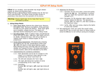
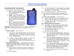
VENTRILOQUIST VOICE RELEASE
USER'S MANUAL
Copyright, 1992
Ventriloquist LLC
807 New Salem Road
Pontotoc, MS 38863
662-488-9344
800-445-3038
WARNING!!!
The user of THE VENTRILOQUIST may inadvertently cause a target to be released or the
device may fail or malfunction. Therefore:
ALWAYS
DISCONNECT THE RECEIVER FROM THE RELEASE CORD/OUTLET
TURN OFF THE TARGET THROWING MACHINE(S), AND
RELEASE THE ARM(S)
BEFORE:
LOADING A MACHINE.
ALLOWING ANYONE ELSE TO LOAD A MACHINE.
PLACING YOURSELF OR ALLOWING ANYONE ELSE TO PLACE THEMSELVES
IN THE FLIGHT PATH OF A TARGET.
NOTICE
The following statement is required for all FCC certified equipment.
This equipment has been tested and found to comply with Part 15 of the FCC rules. These limits are designed to provide reasonable protection
against harmful interference in a residential installation. This equipment generates, uses, and can radiate radio frequency energy and, if not
installed and used in accordance with the instructions, may cause harmful interference to radio communications. However, there is no guarantee
that interference will not occur in a particular installation. If this equipment does cause harmful interference to radio or television reception,
which can be determined by turning the equipment off and on, the user is encouraged to try to correct the interference by one or more of the
following measures:
Reorient or relocate the receiving antenna.
Increase the separation between the equipment and receiver.
Connect the equipment into an outlet on a circuit different from that to which the receiver is connected.
Consult the dealer or an experienced radio/TV technician for help.
Users of The Ventriloquist are authorized under Part 15 of the FCC rules to use this device without a license. However, making any changes or
modifications not expressly approved by the manufacturer may void the user's authority to operate this device.
Copyright, 1992
Ventriloquist LLC
807 New Salem Road
Pontotoc, MS 38863
662-488-9344
800-445-3038
1
THE VENTRILOQUIST brings you an added dimension to your enjoyment of skeet and trap. You are
now free to shoot when YOU want rather than when you can find a puller. You can practice at your
own pace and practice that all important "mental side" of shooting which is so difficult when
surrounded by the "socializing" which usually goes on at the range.
We know that you are anxious to "see IF it works". However, before trying THE VENTRILOQUIST
you should "understand HOW it works.
PAGE 9 OF THIS MANUAL GIVES SPECIFIC INFORMATION ABOUT WIRE-LINKED
VERSION.
THE VENTRILOQUIST is available in TRAP or SKEET versions.
transmitter, a receiver, and a microphone.
Both versions consist of a
The TRANSMITTER attaches to the shooter's belt. The transmitter's microprocessor checks
sounds being sent through the microphone. When it recognizes the call for a target, a coded
message is sent via radio waves to the receiver.
The RECEIVER plugs into the normal outlet used for pull cord by. (See Wiring Instructions
PAGE 10) The receiver's microprocessor checks all signals received. Upon receipt of a correctly
coded message, the program in the microprocessor checks all switch settings and releases the
appropriate target.
The standard lapel mic plugs into the body of the transmitter and may be clipped to your vest or
shirt. (The throat microphone shown in the video tape is available as an extra cost option. ($100.00)
The TRANSMITTER and RECEIVER have controls which allow you to setup THE
VENTRILOQUIST in the way which is most convenient for you. (T = TRAP, S = SKEET.) These
controls are summarized below and explained in detail later in this manual.
The TRANSMITTER CONTROLS are labeled as shown.
T/S
1.
PWR(Power)
Turns transmitter on/off.
S
2.
High, Low, Doubles, Sequence
Selects target to be released.
(SKEET VERSION ONLY.)
T/S
3.
PTR (Push To Release)
Manual target release.
T/S
4.
MICROPHONE SENSITIVITY
Sets minimum level of sound
required to activate “voice”
recognition program.
T/S
5.
TEST
Flashes when “voice” is
recognized and signal transmitted.
T/S
6.
LOW BATTERY
Is lit when the battery is too
low for effective operation.
ACTUAL DIMENSIONS -- 5.5” X 3.5” X 1.25”
2
The RECEIVER CONTROLS are labeled as shown.
T/S
1.
ON/OFF - Turns receiver on/off.
S
2.
RESET - Resets sequence to beginning (High 1).
S
3.
SEQUENCE Selects American or International
target sequence.
S
4.
NUMBER OF SHOOTERS - Sets the number of
shooters (1 to 5).
“DASH” picks International Skeet delay.
“DOT” picks Bad Puller delay.
T/S
5.
DELAY - Sets release time.
NONE
Instantaneous Release
NORMAL
.2 sec. delay (Corresponds to
reaction time of good puller)
INT • BAD International Skeet delay (.1 - 3 sec.)
if Number of Shooters selected by “DASH”
Bad Puller delay (.1 -.35 sec.) if Number of Shooters
selected by “DOT”.
INT • BAD
Bad Puller delay on trap versions.)
6.
LED(s) (Light Emitting Diode) - 2 LEDs on skeet version
show which target is being released (High/Low)
1 LED on trap version shows when target is released.
S
T
T/S
Now you are ready to check out THE VENTRILOQUIST. Use the sequence below:
RECEIVER
T/S
T/S
1.
2.
T/S
T/S
T/S
3.
4.
5.
Remove the receiver from case.
Locate the battery compartment on the bottom of the receiver and remove the cover by
pressing the latch toward the center and lifting up.
Install two (2) nine volt batteries. Pay close attention to polarity (+/-).
Replace cover.
Extend antenna to its full 18 inch length.
TRANSMITTER
T/S
T/S
1.
2.
Remove Transmitter from case.
Locate the battery compartment on the bottom of the transmitter and remove the cover
by pressing the latch toward the center and lifting up.
T/S 3.
Install one (1) nine volt battery. Pay close attention to polarity (+/-).
T/S 4.
Replace cover.
You are now ready to check THE VENTRILOQUIST'S switches.
TURN TRANSMITTER AND RECEIVER ON. (Low battery LED should flash momentarily when
transmitter is turned on -- UP is on.)
TRAP
T
1.
Push the PRESS TO RELEASE (PTR) button on the transmitter and the LED on the
Receiver should light.
3
SKEET
S
1.
S
S
S
S
S
2.
3.
4.
5.
6.
Set the receiver switches:
NUMBER OF SHOOTERS to 1. (Use “DASH” indicator.)
SEQUENCE to AMERICAN.
DELAY to NORMAL.
Press RESET on the RECEIVER.
Press “H” button to select HIGH, push PTR button. The high house LED lights.
Press “L” button to select LOW, push PTR button. The low house LED should light.
Press “D” button to select DOUBLES, push the PTR button. Both LEDs should light.
Push the RESET button on the Receiver and press “S” button to select SEQUENCE,
Now push the PTR button twenty-one (21) times. The LEDs should light in the
sequence of a round of American Skeet. By setting the Sequence switch to
INTRNTNL, pressing the RESET button and pressing the PTR button eighteen (18)
times, you can cycle through an International Skeet sequence.
The American target sequence is:
St. #1 H, L, D.
St. #2 H, L, D.
St. #5 H, L.
St. #6 H, L, D.
St. #3 H, L.
St. #7 H, L, D.
St. #4 H, L.
St. #8 H, L, L.
The International target sequence is:
St. # 1 H, D.
St. # 2 H, D.
St. # 5 L, D.
St. # 6 L, D.
St. # 3 H, D.
St. # 7 D.
St. # 4 H, L, D, D.
St. # 8 H, L.
Now adjust the SENSITIVITY of the microphone.
T/S
1.
T/S
2.
Clip the lapel microphone to your clothing approximately 6-12 inches below your
mouth. Right handed shooters will find the best location is on the left breast pocket.
Plug microphone into jack on the side of transmitter.
TRANSMITTER
S
T/S
3.
4.
T/S
5.
Select a target by pushing a target selection button on the skeet transmitter.
Adjust the SENSITIVITY by turning the knob counter-clockwise to the 3:00 o'clock
position. (Indicator pointing at the base of the MORE arrow.)
Call for the target with your normal call. -- The voice LED on the transmitter and the
target LED on the receiver should light.
Using your normal call, position the microphone at various distances from your mouth.
After a few tries you should have no problem getting a release. If you have a loud call,
the microphone will be further from your mouth than for a soft call. A loud call when
the mic is close to your mouth overpowers the microphone and the noise filter program
rejects the call.
Very small adjustments with the SENSITIVITY knob may be necessary to find the
setting which is best for you. A small adjustment toward the LESS sensitive position
may be necessary if you wish to talk while shooting.
T/S
6.
Once you have set the sensitivity level, place a reference mark on the case.
4
There are two voice circuits available in THE VENTRILOQUIST. The primary voice program is
engaged when the unit is powered up in the normal manner. The alternate, more restrictive, voice
program, is engaged by turning the transmitter off then holding down the PTR button and turning the
unit on. REMEMBER-- the primary program is engaged anytime the transmitter is turned on in the
normal manner.
The primary program accepts a broader range of voices and will work fine under most conditions. The
alternate program is more restrictive and may be necessary when shooting at a very active club.
HINTS FOR ADJUSTING MICROPHONE
We have found the following very useful in explaining how the voice circuit and the microphone
adjustment works.
•
•
The LAPEL microphone is position sensitive.
This means that the microphone is much like your ear. If you are at a gathering where music is
being played and you can’t hear, you move closer. If the music is too loud you move further away.
If you get too far away, you can’t understand the words; and if you get too close the words are
distorted so much that you can’t understand.
• The microphone for the VENTRILOQUIST is much the same. If the microphone is too close to
your mouth, the sound is distorted and the microprocessor will not accept it as voice. If the
microphone is too far away from your mouth, the sound is not loud enough to trip the voice circuit.
• The minimum amount of sound that it takes to “trip” the voice circuit is preset inside the
TRANSMITTER. This voice circuit must be tripped before the microprocessor will analyze the
sound to see if it is voice.
• The MICROPHONE SENSITIVITY control is used to raise this minimum trip point.
•
1.
To keep normal conversation from tripping the voice circuit.
•
2.
To “train” your voice to call in a clear distinct manner each and every time.
Many people tend to call softer as they progress through a round. This makes it hard
for the referee to hear and bad pulls are the result. By setting the MICROPHONE
SENSITIVITY control tighter (less sensitive), you can “train” your voice to give clearer
calls. It will help when it counts.
• The natural tendency when a target is not released is to shout. Shouting is counter-productive
because it distorts the voice and the microprocessor will not accept it.
• Most users find they can release targets with the MICROPHONE SENSITIVITY control set at
approximately the 3 o’clock position with the microphone attached on the left breast pocket (right
handed shooter).
• Do not set the MICROPHONE SENSITIVITY control in the most sensitive position because it
forces a delay of about 1 second for the PUSH TO RELEASE BUTTON. You must wait about 1
second between pushes of the button.
WHAT ALL THIS MEANS: If you do not have a clear distinct call, you will have to experiment
with the microphone location until you find a location that will allow you to release a target with the
MICROPHONE SENSITIVITY set to about the 3:00 o’clock position (Indicator pointing at the base
of the MORE arrow.)
5
QUESTIONS/ANSWERS
The easiest way to understand THE VENTRILOQUIST is to read the responses to the questions we
answered in the process of developing THE VENTRILOQUIST.
T/S
Q.1.
How far will THE VENTRILOQUIST transmit its signal?
A.1.
T/S
Q.2.
Will I have trouble with interference?
A.2.
T/S
Q.3.
Q.4.
Q.5.
Q.6.
Q.7.
Q.8.
Q.9.
Q.10.
These units have been used extensively during the winter in cold states. No
problems have been reported.
Can THE VENTRILOQUIST be placed in the trap or skeet house?
A.9.
T/S
We have taken reasonable precautions to make THE VENTRILOQUIST
resistant to inclement weather. However, you should not allow the transmitter
or the receiver to get wet. You can place the receiver in a plastic bag with no
reduction in effectiveness.
Can THE VENTRILOQUIST be used in cold weather?
A.8.
T/S
THE VENTRILOQUIST is set up to use the microphone provided. Using
another microphone may create problems and may void the warranty.
Is THE VENTRILOQUIST weatherproof?
A.7.
T/S
THE VENTRILOQUIST is warranted to be free from manufacturing defects for
a period of one year.
Can I use another microphone?
A.6.
T/S
Call 800-445-3038 for help.
What is the warranty?
A.5.
T/S
Under normal conditions, they will last about 5,000 targets.
What do I do if THE VENTRILOQUIST fails to work as I think it should?
A.4.
T/S
The microcomputers in the transmitter and receiver have been programmed to
ignore any interference.
How long will the batteries last?
A.3.
T/S
All units are tested at 100 yards before shipping. Local conditions may
influence the range. However, you should get consistent releases from 50 yards
under all conditions. For this reason, you should always disconnect the unit
before working around a target machine.
We do not recommend this practice for safety reasons.
Another shooter at my club has THE VENTRILOQUIST. Can we shoot on adjoining
fields without interference?
A.10. Yes. However, one of you may have to change the field code setting on your
transmitter and receiver. If this is necessary, see page 14.
6
T/S
Q.11.
Another shooter at my club has THE VENTRILOQUIST. Can we shoot on the same
field using one receiver?
A.11. Yes. Both machines are capable of sending a common code. If you experience
problems, call 1-800-445-3038. (Skeet Only) - Set the NUMBER OF
SHOOTERS switch on the receiver to the total number of shooters in your
squad.
T/S
Q.12.
How do I wire in THE VENTRILOQUIST?
A.12. See separate Wiring Instructions. Page10
T/S
Q.13.
Can I damage THE VENTRILOQUIST by connecting it incorrectly?
A.13. Damage is possible. However, if you exercise reasonable care in making the
connections you are not likely to damage THE VENTRILOQUIST. If you have
any questions about making connections call 800-445-3038.
T/S
Q.14.
Will THE VENTRILOQUIST recognize only "PULL"?
A.14. THE VENTRILOQUIST will release a target each time it recognizes "voice" at
the adjusted volume level. Be sure to use your normal call when making
adjustments.
T/S
Q.15.
Can I talk when using THE VENTRILOQUIST?
A.15. Yes, provided that you do not speak as loudly as you call for the target. THE
VENTRILOQUIST is programmed to recognize "voice". The SENSITIVITY
control is provided to set the level of "voice" recognized. A setting on the
SENSITIVITY control which will require a strong "PULL" command will
allow you to talk in normal tones.
T
Q.16.
What if there are two or more of us who want to shoot trap?
A.16. You may use THE VENTRILOQUIST with a squad of shooters by voice
releasing your own targets, and using the PTR button on the transmitter to
manually release the targets for the remaining shooter(s). You may also use a
transmitter for each shooter with a single receiver and voice release all targets.
S
Q.17.
What if there are two or more of us who want to shoot skeet?
A.17. You may use THE VENTRILOQUIST with up to (5) shooters by setting the
NUMBER OF SHOOTERS switch on the receiver to the desired number,
releasing your own targets by VOICE, and using the PTR button on the
transmitter to manually release the targets for the remaining shooter(s). You
may also use more than one transmitter with a receiver and voice release all
targets.
S
Q.18.
What do I do when I need to shoot my option?
A.18. You shoot your option by selecting the proper target on the transmitter (HIGH
or LOW), shooting the target, and then selecting SEQUENCE.
S
Q.19.
What do I do when I get a broken target?
A.19. As with the option, you select the proper target(s) on the transmitter, (HIGH,
LOW, DOUBLES) shoot the target(s), and then select SEQUENCE.
7
S
Q.20.
Can I program my own sequence?
A.20. No. THE VENTRILOQUIST is programmed to throw an American or
International Skeet sequence. You may manually select any sequence of targets
by using the target selection switches. See Question 26.
S
Q.21.
Must I start THE VENTRILOQUIST at Station 1, High?
A.21. Yes. You cannot start a round anywhere except Station 1, unless you disconnect
the release cord and step through the sequence to the point where you want to
start.
S
Q.22.
What if I accidentally release a target when the transmitter is set to SEQUENCE?
A.22. Use the procedure prescribed for the option. Select the target which was
accidentally released, shoot that target, and then select SEQUENCE.
T/S
Q.23.
How quickly can I call for a second target?
A.23. THE VENTRILOQUIST will not accept a voice signal for 2 seconds following
the release of a target. This feature is designed to accommodate the target
machine cycle time of approximately 2 seconds.
T/S
Q.24.
I’ve heard that voice release systems are slow. Is this true of THE VENTRILOQUIST?
A.24
T/S
Q.25.
How do I activate the BAD PULLER DELAY?
S
A.25. Use “DOT” on the Number of Shooters Switch to select the number of shooters
and then set the DELAY switch to the middle position (INT • BAD).
T
S
S
THE VENTRILOQUIST is capable of releasing target faster than a human
puller. Because of this, we have provided a switchable delay option. This
option allows you to select from three delay option: NO DELAY, NORMAL
DELAY, and BAD PULLER DELAY.
Set the DELAY switch to the middle position (INT • BAD).
Q.26.
How can I practice the entire sequence for station 1,2,6 or7 over and over.
S
A.26. To repeatedly shoot stations 1,2,6,and 7 (H,L,D), set the Number of Shooters
switch to 5 shooters, the Ventriloquist will throw 10 sequences of H, L, D
Q.27.
How can I practice the entire sequence for station 3,4 or 5 over and over.
S
A.27. To repeatedly shoot stations 3,4, or 5 (H,L), set the Number of Shooters switch
to 5 shooters, unplug the Receiver and use the PTR button to step through the 10
sequences of H,L,D. You will then have 15 sets of H,L
8
WIRE-LINKED VERSION
The WIRE-LINKED version of THE VENTRILOQUIST links to the target machine via a 100 ft. cord
rather than through a radio transmitted signal. The WIRE-LINKED version shown below features a
custom belt and holster to secure the control unit. A stress relief strap connects the control cord to the
belt to protect the unit from damage. This strap has a quick release clip which allows the shooter to
disconnect the cord from THE VENTRILOQUIST without removing the belt and holster. Other
features are explained below.
T/S
S
T/S
T/S
1.
2.
3.
4.
T/S
T/S
T/S
used
5.
6.
7.
The CONTROLS are labeled as shown.
PWR(Power) Turns unit on/off.
H(igh), L(ow), D(oubles), S(equence) Selects target to be released. (SKEET ONLY.)
PTR (Push To Release) Manual target release.
MICROPHONE SENSITIVITY Sets minimum level of sound required to activate
“voice” recognition program.
T or H L Flashes when “voice” is recognized and relays are closed.
LOW BATTERY Is lit when the battery is too low for effective operation.
OPTION CODE SWITCH (not labeled) provides the options shown below. When
for trap shooting this switch would be set at “0”, “1”, or “2”.
OPTION CODE SWITCH
0 = > American Sequence, 1 Shooter, Normal Delay
1 = > American Sequence, 1 Shooter, No Delay
2 = > American Sequence, 1 Shooter, Bad Puller
Delay
3 = > American Sequence, 2 Shooters, Normal Delay
4 = > American Sequence, 3 Shooters, Normal Delay
5 = > American Sequence, 4 Shooters, Normal Delay
6 = > American Sequence, 5 Shooters, Normal Delay
7 = > International Sequence, 1 Shooter, International
Delay
8 = > International Sequence, 2 Shooters,
International Delay
9 = > International Sequence, 3 Shooters,
International Delay
9
WIRING INSTRUCTIONS
First, a definition. The word common is used throughout this text to describe the voltage level
(115VAC or ground) that is being switched. The use of this word is not meant to infer any particular
voltage level, ground or neutral.
The cable on the SKEET version of the VENTRILOQUIST has three wires.
The black wire is connected to the high house relay in the VENTRILOQUIST.
The white wire is connected to the low house relay in the VENTRILOQUIST.
The green wire is connected to the common in the VENTRILOQUIST.
When wiring a plug to the VENTRILOQUIST, the black wire should be connected to the high house
terminal, the black wire to the low house terminal, and the green wire to the common terminal.
THE CABLE ON THE TRAP VERSION OF THE VENTRILOQUIST HAS TWO WIRES. ONE
IS BLACK THE OTHER IS WHITE. THE POLARITY OF THESE WIRES IS NOT
IMPORTANT. THEY MAY BE CONNECTED IN EITHER ORDER TO THE TERMINALS OF
THE PLUG.
There are two common ways that the release circuits on skeet fields are arranged.
In one scheme, 115VAC is switched (the common) through the release switch, to one terminal
of the arm-release solenoid of the target machine and the other terminal of the solenoid is
connected to ground(neutral).
The other scheme switches ground (neutral) to one terminal of the release solenoid and has the
other terminal of the solenoid connected to 115VAC.
It does not matter to the VENTRILOQUIST which scheme is used. Whatever (115VAC or ground) is
being switched is used as the common.
The terminals on your release outlet must be identified so that the correct connections can be made to
the VENTRILOQUIST.
METHOD #1 -- The following is a step by step method of identifying the terminals of your
release outlet so THE VENTRILOQUIST may be corrected correctly. (If you do not have some
experience with electricity and access to an AC voltmeter we suggest that you avail yourself of
the services of a competent electrician.)
1.
Power up the field.
2.
Set voltmeter for correct range to read 115VAC.
3.
Read between the terminals of the skeet release outlet in a systematic manner
until you find a pair that has no reading (0 volts). One of these is the high and the
other is the low. The third terminal is the common. Mark the common in some
manner.
4.
Now, to determine which is the high and which is the low. Use a jumper to
connect between the common found in step #3 and one of the terminals we
determined to be the high and the low. A target will be thrown when this
connection is made. Whichever target is thrown is the one assigned to that
terminal. e.g. If the high house target is thrown, the terminal you connected to
the common is for the high house machine and the other is for the low house
machine. Jump between the other wire and common to throw the other target.
5.
Connect the wires in the VENTRILOQUIST cord to a plug that matches your
release outlet. Black to high/White to low/Green to common.
The plug fits in the outlet in reverse from the way it looks when your front view the outlet.
METHOD #2 -- This method requires your release cord and an ohmmeter or continuity tester.
1
Disconnect the release cord from the outlet, set the meter to read ohms.
10
2.
Read between pairs of wires until you find a pair that show continuity. (If you
can’t find two with continuity go to method #3.) One of these is the high and the
other is the low. The third is the common, mark it in some way.
3.
Connect your meter between the common and one of the two wires found above.
4.
Push the high button on the release. If the meter shows continuity then this is the
high house wire, if the meter does not show continuity connect between the other
wire and common and press the high button. The meter should show continuity.
The wire that shows continuity with the button pressed is assigned to high house.
5.
Connect the meter between the other wire and press the low house button, you
should show continuity. This is the low house wire.
6.
Press the doubles button you should have continuity. Connect the meter between
the common and high wire and press the high button, you should show
continuity.
7.
Connect the wires in the VENTRILOQUIST cord to a plug that matches your
release outlet. Black to high/White to low/Green to common.
The plug fits in the outlet in reverse from the way it looks when your front view the outlet.
METHOD #3 -- This method requires your release cord and an ohmmeter or continuity tester.
1.
Connect meter between any pair of wires. Press the high button. Do you have
continuity? NO, skip to step #7. Yes, go to step #2.
2.
One of these is the common the other is the high. Mark both of these wires.
3.
Leave one wire hooked to the meter, move the other meter lead to the third wire.
4.
Press the low button. Is there continuity? No, skip to step #6 Yes, go to step #5.
5.
The wire you left hooked up in step #3 is the common. The third the wire is the
low wire and the wire you disconnected in step #3 is the high wire.
6.
The wire you disconnected in step #3 is the common, the third wire is the low
wire and the wire you left connected is the high.
7.
Press the low button. Is there continuity? No, go to step #13. Yes, go to step #8.
8.
One of the is the low the other is the common. Mark both of these in some way.
9.
Leave one wire hooked to the meter, move other meter lead to third wire.
10.
Press the high button. Is there continuity? No, go to step #12. Yes, go to step
#11.
11.
The wire you left connected in step #9 is the common, the third wire is the high
and the one you disconnected in step #9 is the low.
12.
The wire you disconnected in step #9 is the low and the third wire is the high.
13.
The wires you have connected to the meter are the wires for the low and the high.
Mark these wires in some way.
14.
Leave one wire connected. Move the other meter lead to the third wire.
15.
Press the high button. Is there continuity? No, skip to step #16. Yes, the third
wire is the common, the other wire connected to the meter is the high and the
wire you disconnected in step #14 is the low.
16.
Press the low button. Is there continuity? NO, you or I one have screwed up.
You should have continuity. The third wire is the common, The other wire
connected to the meter is the low and the wire disconnected in step #14 is the
high.
17.
Connect the wires in the VENTRILOQUIST cord to a plug that matches your
release outlet. Black to high/White to low/Green to common.
11
12
13
How to change the Field Code
The Flat on the shaft points to the # selected
RECEIVER:
1
Remove Batteries.
2
Use small flat screwdriver to turn knob through the hole in the battery housing.
3
Select 0, 1, 3, 4, 5, 6, 7.
4
Replace batteries
TRANSMITTER:
1 Remove battery.
2 Remove 4 Philips screws in back cover.
3 Slide case apart.
4 Set S5 to the same setting as Receiver
5 Slide cover back together.
6 Replace screws.
7 Replace battery.
14