1
INDEX
MOUNTING REQUIREMENTS...................................1
CONNECTIONS..........................................................2
INSTRUMENT CONFIGURATION..............................5
Run time and configuration modes ......................5
General note about graphic symbols used
for mnemonic code visualization .........................5
Keyboard description...........................................6
Hardware setting .................................................7
CONFIGURATION MODE ..........................................8
Monitor mode ......................................................8
Modify mode........................................................9
CONFIGURATION PARAMETERS ........................10
RUN TIME MODE .....................................................18
Alternative functions of the display ....................18
Indicators...........................................................19
Run Time parameters ..............................................19
Output power off function .........................................40
SP - SP2 selection ............................................40
Direct access to the set point ............................40
Lamp test...........................................................41
Loop break alarm ..............................................41
SMART function.................................................42
ERROR MESSAGES ................................................43
GENERAL INFORMATIONS ....................................46
DEFAULT PARAMETERS ..................................... A.1
SECURITY CODES ............................................... A.2
GENERAL INFORMATIONS ....................................47
CTD 24
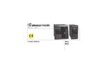
MOUNTING REQUIREMENTS
This instrument is intended for permanent installation,
for indoor use only, in an electrical panel which
encloses the rear housing, exposed terminals and
wiring on the back. Select a location, for instrument
mounting, where minimum vibrations are present and
the ambient temperature is within 0 and 50 ° (32 and
122 OF).
Bracket
Gasket
The instrument can be mounted on a panel up to 15
mm thick with a 45 x 22.2 mm square cutout. For
outline and cutout dimensions refer to Fig. A. The
surface texture of the panel must be better than 6.3
µm.
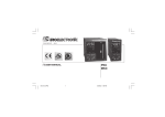
The instrument is shipped with rubber panel gasket.
Gasket
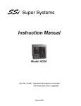
To assure the IP65 and NEMA 4 front protection,
insert the panel gasket between the instrument and
the panel as shown in fig. 1.
For the instrument mounting proceed as follows:
1) insert the gasket in the instrument case;
2) insert the instrument in the panel cutout;
3) pushing the instrument against the panel, insert the
mounting bracket and press it against the panel.
1/48
Panel
Fig. 1
CONNECTIONS
Screw terminals from n° up to 6 (screw M2.6, for cables from f 0.25 to f 2.5 mm2 or from
AWG 22 to AWG 14, max torque 0.4 Nm).
Screw terminals from n° up to 9 (screw M2, for cables from f 0.25 to f 0.75 mm2 or from
AWG 22 to AWG 18, max torque 0.25 Nm).
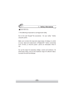
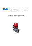
A) MEASURING INPUTS
NOTE: Any external component (like zener barriers etc.) connected between sensor
and input terminals may cause errors in measurement due to excessive and/or not
balanced line resistance or possible leakage currents.
External resistance: 100 Ω max,
maximum error 0,1% of span.
Cold junction: automatic compensation
from 0 to 50 °C.
Cold junction accuracy: 0.1 °C/°C
Input impedance: > 1 MΩ
NOTES:
1) Don't run input wires together with
power cables.
Fig. 2 THERMOCOUPLE INPUT WIRING
2) For TC wiring use proper
compensating cable preferable
shielded.
3) When a shielded cable is used, it should be connected at one point only.
2/48
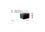
RTDINPUT
Input: for RTD Pt 100 Ω, 3-wire
connection.
Line resistance: automatic
compensation up to 25 Ω /wire with
no measurable error.
NOTES:
1) Don't run input wires together with
power cables.
2) Pay attention to the line
resistance; a high line resistance
may cause measurement errors.
3) When shielded cable is used, it should be
grounded at one side only to avoid ground
loop currents.
Fig. 3 RTD INPUT WIRING
4) The resistance of the 3 wires must be the same.
LINEAR INPUT
NOTES:
1) Don’t run input wires
together with power
cables.
2) Pay attention to the line
resistance; a high line
resistance may cause
measurement errors.
3) When shielded cable is used, it
should be grounded at one side only
avoid ground loop currents.
Input type
17
0 - 60 mV
18
12 - 60mV
Impedance
Accuracy
> 1 Ma
0.2 % + 1 digit
@ 25°
3/48
Fig. 4 mV INPUT WIRING
to
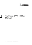
B) RELAY OUTPUTS
The contact rating the relay outputs
3A/250V AC on resistive load.
The number of
operations is 1 x 10⁵ at
specified rating.
is
Out 1
NOTES:
Out 2
1) To avoid electrical
shock, connect power
at the end of the wiring procedure.
2) For power connections use No
14 A WG rated for at last 75 °C.
line
16 or
Fig. 5 RELAY OUTPUTS WIRING
3) Use copper conductors only.
4) Don't run input wires together with power cables.
All relay contacts are protected by varistor against inductive load with inductive
component up to 0.5 A.
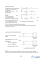
VOLTAGE OUTPUTS FOR SSR DRIVE
They are time proportioning
outputs.
Logic level 0: Vout < 0.5 V DC.
Out 1
Out 2
Logic level 1:
-14 V ± 20 % @ 20 mA
-24 V ± 20 % @ 1 mA.
Maximum current = 20 mA.
Fig. 6 SSR DRIVE OUTPUTS
NOTE: These outputs are not isolated. A double or reinforced isolation between
instrument output and power supply must be assured by the external solid state relay.
4/48
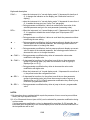
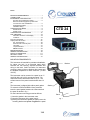
C) POWER LINE WIRING
- 100V to 240V AC 50/60Hz
(-15% to + 10% of the
nominal value).
- 24 V AC/DC (± 10 % of the
nominal value).
NOTES:
Fig. 7 POWER LINE WIRING
1) Before connecting the instrument to the
power line, make sure that line voltage corresponds to the description on the identification label.
2) To avoid electrical shock, connect power line at the end of the wiring procedure.
3) For supply connections use No 16 AWG or 14 AWG rated for at last 75 °.
4) Use copper conductors only.
5) Don't run input wires together with power cables.
6) For 24 V DC the polarity is a do not care condition
7) The power supply input is NOT fuse protected.
Please, provide it externally.
Power supply Type
Current
Voltage
24 V AC/DC
T
500 mA
250 V
100/240 V AC
T
125 mA
250 V
When fuse is damaged, it is advisable to verify the power supply circuit, so that it is necessary to send
back the instrument to your supplier.
8) The safety requirements for Permanently Connected
Equipment say:
- a switch or circuit-breaker shall be included in the building installation;
- It shall be in close proximity to the equipment and within easy reach of the operator;
- it shall be marked as the disconnecting device for the equipment.
NOTE: a single switch or circuit-breaker can drive more than one instrument.
9) When a neutral line is present, connect it to terminal 1.
INSTRUMENT CONFIGURATION
Run time and configuration modes
General notes
When the instrument is in run time mode and no modification parameter is in progress, the instrument
displays the measured variable (we define this condition “normal display mode").
The instrument parameters are divided in two families:
- Run time parameters (formed by the groups 1, 2,
3, 4, 5, 6, default and hidden).
- Configuration parameters
At power up, the instrument starts in the same mode
(configuration or run time) it was prior to the power
OFF.
General note about graphic symbols used for
mnemonic code visualization.
The instrument displays some characters with special
symbols.
The following table shows the correspondence
between the symbols and the characters.
5/48
Keyboard description
FUNC =
□ when the instrument is in "normal display mode", if depressed for less than 4
S., it changes the indication on the display (see "Alternative function of
display”).
□ when the instrument is in "normal display mode”, if depressed for more than 4
S., it enables the lamp test (see "Lamp Test" paragraph).
□ During parameter modification, it allows to memorize the new value of the
selected parameter and go to the next parameter (increasing order).
REV =
□ When the instrument is in "normal display mode", if depressed for more than 4
S., it is possible to disable the control output (see "Output power OFF"
paragraph).
□ During parameter modification, it allows to scroll back the parameters without
memorizing the new setting.
▲
=
□ During parameter modification, the first pressure allows to display the current
value or status of the selected parameter, the following pressure allows to
increase this value or to change the status.
▼
=
□ During parameter modification, the first pressure allows to display me current
value or status of the selected parameter, the following pressure allows to
decrease this value or to change the status.
▲ + FUNC =
□ During parameter modification they allow to increase the value under
modification with higher rate.
▼ + FUNC =
□ If depressed for less than 4 s. they allow to scroll the run time parameter
groups in increasing order (only when the mnemonic code of a group is
displayed [for ex. Gr.1]).
□ During parameter modification they allow to decrease the value under
modification with higher rate.
□ When the instrument is in "normal display mode., if depressed for more than 4
s., they allow to start the configuration mode.
▲ + REV =
□ If depressed for less than 4 s. they allow to scroll the run time parameter
groups in decreasing order (only when the mnemonic code of a group is
displayed [for ex. Gr.1]). 0 During parameter modification they allow to jump
to the max. programmable value.
▼ + REV =
□ During parameter modification they allow to jump to the min. programmable
value.
NOTES:
1) All the actions above explained which require the pressure of two or more keys must follow
exactly the keys sequence shown.
2) A 10 or 30 seconds time out (see nt10uH) can be selected for parameter modification during
run time mode.
If, during parameter modification, no key is depressed for more than 10 (30) seconds, the
instrument goes automatically to the "normal display mode" and the eventual modification of
the last parameter will be lost.
6/48
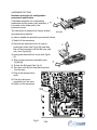
HARDWARE SETTING
Hardware protection for configuration
parameters modification
A hardware protection for configuration
parameters modify mode is also available, it
is located on the solder side of the
instrument circuit.
The instrument is shipped from factory without
any parameter protection.
AFig.8a
In order to enable this protection proceed as follows:
1) Switch off the instrument.
2) Remove the instrument from its case by
pushing the locks (see Fig.8a [A]) and then
slip out the instrument until the first stop (few
mm.) (see Fig.8a [8]).
3) Unplug the terminal block cover (see Fig.8b
[C).
4) Slip out the instrument completely (see
Fig.8b [0]).
5) Solder the Sh2 pads (See Fig. 9).
6) Re-insert until the first stop the instrument
into the case.
7) Plug-in the terminal block
cover.
8) Push the instrument
completely into the case.
9) Switch on the instrument.
Fig.9
7/48
Fig.8b
CONFIGURATION MODE
The instrument will start in the same way it was prior to the power down (configuration mode or
run time mode).
a) If the instrument starts in run time mode, depressing the ▼ + FUNC for more than 4 seconds
the instrument will show:
By pushing the FUNC key, it is possible to select between:
- monitor mode;
it is possible to verify all the configuration parameters without stopping the control.
- modify mode;
it is possible to verify and to modify all the configuration parameters, the control will be
stopped.
NOTE:
If no push-button is depressed for more than 10 s (or 30 s according to “t1ou" [time out
selection] parameter setting), the instrument returns automatically to the normal display mode.
b) If the instrument starts in configuration modify mode, the display will show:
It is the first configuration parameter displayed in modify mode.
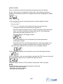
MONITOR MODE
When it is desired to monitor the instrument configuration, proceed as follows:
1) By the ▲ or ▼ key select the monitor mode, the display will show:
2) Push the FUNC key the display will show:
it is the first parameter of the configuration group displayed in monitor mode.
3) Press the FUNC key to scroll through parameters.
4) Press the ▲ or ▼ key to display the value or status of the selected parameter.
5) It is possible to return in normal display mode:
- manually; by pushing the ▼ + FUNC keys when the display shows “ConF".
- automatically; at the end of the time out (see note 2).
NOTES:
1) During monitor mode, the instrument continues to operate as in run time mode.
2) If no push-button is depressed for more than 1 0 s (or 30 s according to “t1ou” [time out
selection] parameter setting), the instrument returns automatically to the normal display mode.
8/48
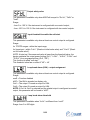
MODIFY MODE
When it is desired to modify the configuration parameters proceed as follows:
By ▲ or ▼ key select the configuration modify mode, if the hardware protection is
disabled (see Hardware protection for configuration parameters paragraph) the display
will show:
Push the FUNC key.
1) If the configuration group is protected by security code the display will show:
1.A) By A and T keys enter a value equal to the security code set for the
configuration mode or the master key (see appendix A).
Note: the master key allows to enter in modify configuration parameters mode
either if any other configuration security code is set or if the configuration
parameters are always protected (S.CnF = 1).
Push the FUNC key, the display will show:
It is the first parameter of the configuration group and the parameter
modification is started.
Press the FUNC key to scroll through parameters, when the parameter to be
modified has been reached, change its value or status by ▲ and ▼ keys.
1.B) If the value is different from the security code, the display will show:
2) If the configuration group is not protected by security code the display will show:
When it is desired to return to normal display mode push the FUNC key more times until
the configuration parameter end is reached, the display will show:
by ▲ and ▼ keys, select the "YES" indication, then push the FUNC key again.
NOTE:
During the modify mode, the instrument stops the control and:
- sets to OFF the control outputs;
- sets alarms in no alarm condition;
- the time out will be removed.
9/48
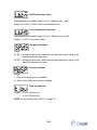
CONFIGURATION PARAMETERS
Some of the following parameter may be skipped according to the instrument
configuration.
Default configuration parameter loading
Range:
OFF = No loading data
dF.t1= Loading European Table (Tb.1) default parameters.
dF.t2 loading Am9r:ican Table (Tb.2) default parameters.
NOTES:
1) the list of both default parameter tables is reported at Appendix A.
2) see also the note of the .Cn.tP" configuration parameter at page 11.
Input type and standard range
Ranges:
*
*
*
*
1 = TC type
2 = TC type
3 = TC type
4 = TC type
5 = TC type
6 = TC type
7 = TC type
* 8 = RTD Pt100
9 = TC type
10 = TC type
11 = TC type
12 = TC type
13 = TC type
14 = TC type
15 = TC type
* 16 = RTD Pt100
17 = Linear
18 = Linear
L
J
K
T
N
S
R
L
J
K
T
N
S
R
range
range
range
range
range
range
range
range
range
range
range
range
range
range
range
range
range
range
-100
-100
-100
-200
-100
-50
-50
-200
-150
-150
-150
-330
-150
-60
-60
-330
0
12
/
+900 °C
/ +1000 °C
/ +1370 °C
/
+400 °C
/ +1400 °C
/ + 1760 °C
/ +1760 °C
I
+850 °C
I +1650 °F
I +1830 °F
I +2500 °F
I
+750 °F
I +2550 °F
I +3200 °F
I +3200 °F
I +1560 °F
I
60 mV
I
60 mV
* For these ranges it is possible to select a readout with one decimal figure, in this case the
instrument cannot display a measure lower than -199.9 or higher than 999.9 and the input range
will be limited by it.
NOTE:
When input type has been changed, the instrument automatically forces:
- the "ñ.In.L" and "SS.th" parameters to the new initial scale value (0 for linear range),
- the "ñ.ln.H" parameter to the new full scale value (4000 for linear range),
- the "ñ.ln.d" parameter to " no decimal figure".
10/48
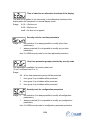
Decimal point position
This parameter is available only for the input types 1 up to 4, 8, 16 up to 18.
----. = No decimal figure.
---.- = One decimal figure.
--.-- = Two decimal figures.
-.--- = Three decimal figures.
NOTES:
1) For input types 1 to 4, 8 and 16 only the "no decimal figure" and "one decimal figure"
are selectable, the input range is limited within -199.9 and 999.9 and it acts as an
input type changement.
2) For linear input types (17 and 18), all positions are available.
Readout - initial scale value
Range:
For linear inputs it is programmable from -1999 to 9999. For TC and RTD inputs
it is programmable from initial range value to "ii.ln.H" parameter (readout full
scale value).
NOTES:
1) Changing the "ii.ln.l" value, the "rl" run time parameter will be aligned to it, if the new
value is higher than the SP (and/or SP2) value, the SP (and/or SP2) value will be
aligned to "rl".
2) If a linear input is selected, the "SS.th"(lnput threshold to enable the soft start)
configuration parameter will be aligned as well. .
3) If a linear input is selected, the value of this parameter can be greater than "ii.ln.H" in
order to get a reverse readout.
J Readout - full scale value
Range:
For linear inputs it is programmable from -1999 to 9999. For TC and RTD inputs
it is programmable from "ii.ln.l" (readout initial scale value) to full range value.
NOTES:
1) Changing the "ii.ln.H" value. the "rHO run time parameter will be aligned to it, if the
new value is lower than the SP (and/or SP2) value, the SP (and/or SP2) value will be
aligned to Nrl".
2) The programmed input span, in absolute value, must be greater than:
300 ° or 550 of for TC inputs;
100 ° or 200 of for RTD inputs;
100 digits for linear inputs.
3) If a linear input is selected, the value of this parameter can be smaller than "ii.ln.l" in
order to get a reverse readout.
11/48
Input offset adjustment
Range: from -500 to 500 digits.
NOTES:
1) The decimal point will be automatically positioned as selected for the main
input.
2) The offset value will be algebraically added to the input process value.
Filter on the measured value
Ranges:
NonE =
1 =
2 =
4 =
8 =
12 =
16 =
20 =
NOTES:
no digital filter
filter with 1 second time constant
filter with 2 seconds time constant
filter with 4 seconds time constant
filter with 8 seconds time constant
filter with 12 seconds time constant
filter with 16 seconds time constant
filter with 20 seconds time constant
1) This is a first order digital filter applied to the measured value.
2) This filter has effect on all instrument functions (display, alarms, self-tuning, control).
OUT 1 function
Range: nonE
FiAin
SECn
ALr.1
=
=
=
=
Output not used
Time proportional main control output
Time proportional secondary control output
Alarm 1 output
12/48
OUT 2 function
Range: nonE
FiAin
SECn
ALr.2
=
=
=
=
Output not used
Time proportional main control output
Time proportional secondary control output
Alarm 2 output
Smart function
This parameter is available only when at least one control output is configured.
Range: dlS = Smart function disabled.
Enb = Smart function may be enabled.
Control action type
This parameter is available only when at least one control output is configured.
Range: Pid = The process is controlled by PID action.
Pi = The process is controlled by PI action.
Note: if the control action type was changed and the configuration procedure has
been enabled while the second part of the SMART algorithm (ADAPTIVE) was in
progress, the HPb" and Hti" parameters will be updated with the values
calculated by the first part (TUNE) of the SMART for the new type of control
action.
If these values are wrong the following actions occur:
- the HE.120" error message is displayed for 2 seconds,
- the IIPbR and RtiR parameters will not be updated,
- the instrument will work as PI controller ("td" parameter will be forced to 0).
It is advisable to restart the SMART algorithm.
Condition for output safety value
This parameter is available only when at least one control output is configured.
Ranges:
Std.
= No safety value ("standard setting" see chapter ERROR MESSAGES).
Ov. Un = Safety value applied when the instrument detects an overrange or
underrange condition of the input.
OvEr = Safety value applied when the instrument detects an overrange
condition of the input.
Undr
= Safety value applied when the instrument detects an underrange
condition of the input.
13/48
Output safety value
This parameter is available only when ASECnA is equal to "Ov.Un", "OvEr" or
"Undr".
Range:
- from 0 to 1 00 % if the instrument is configured with one control output;
- from -100 % to 100 % if the instrument is configured with two control outputs.
Input threshold to enable the soft start
This parameter is available only when at least one control output is configured.
Range:
for TC/RTD ranges - within the input range;
for linear input - within "ñ.ln.L" (Read-out initial scale value) and " ñ.ln.H" (Readout full scale value").
NOTE: At start up if the measured value is lower than the threshold value, the
device maintains the output power limiting (Gr.5, " ñ.OLL", " ñ.OLH", "S.OLL" and
"S.OLH") for a programmed time (Gr.5, "tOL").
This function is called "soft start"
This threshold value has no effect if "tOl" = InF
Loop break alarm (LBA) – output assignment
This parameter is available only when at least one control output is configured.
Range:
nonE = Function disabled
diSP = The LBA is signaled on display only
Out1 = The output 1 is used as output for LBA
Out2 = The output 2 is used as output for LBA
NOTE: If Out1 or Out 2 is selected and the related output is configured as control
output, this parameter will be forced to “diSP”.
Loop break alarm threshold
This parameter is available when “l.b.AL” is different from “nonE”.
Range: from 0 to 500 digits
14/48
LOOP break alarm timer
This parameter is available when “L.b.AL” is different from “nonE” .
Range: from 00.01 to 40.00 mm.ss (minutes/seconds)
Loop break alarm hysteresis
This parameter is available when "L.b.AL” is different from “nonE".
Range: 1 to 50% of the power output
Set point indication
Range:
Fn.SP = during run time mode, when the instrument performs a ramp, it will
show the final set point value.
OP.SP = during run time mode, when the instrument performs a ramp, it will
show the operative se1 point.
Set point available
Range:
1 = Only the main set point is available
2 = Main and auxiliary set point are available
Time out selection
Range:
tñ.10 = 10s time out
tñ.30 = 30s time out
NOTE: for more details see “NOTE 3” at page 15.
15/48
Time of selection on alternative functions of the display
This time out is applied, in run time mode, to the alternative functions of the
display when the instrument is in normal display mode.
Range:
tñ.10 = 10s time out
tñ.30 = 30s time out
nonE = No time out is applied
Security code for run time parameters
Range: 0
1
No protection (it is always possible to modify all run time
parameters);
always protected (it is not possible to modify any run time
parameter);
from 2 to 9999 security code for run time parameter protection.
Run ti.me parameter groups protected by security code
This parameter is available if a security code is set
(“S.run” is different from 0 or 1).
Range:
All
all run time parameters groups will be protected,
1
from group 2 up to hidden will be protected,
2
from group 3 up to hidden will be protected,
3
from group 4 up to hidden will be protected.
Security code for configuration parameters
Range: 0
1
No protection (it is always possible to modify all configuration
parameters);
always protected (it is not possible to modify any configuration
parameter);
from 2 to 9999 security code for configuration parameter protection.
16/48
General notes about security codes
1) If a value from 2 to 9999 has been assigned as security code it cannot be
displayed anymore, when returning on this parameter the display will show
“On”.
2) If the security code is forgotten a new value can be set.
3) For configuration parameter only is available a master key, by this code it is
possible to enter in modify configuration mode even if the configuration
parameters are protected (S.CnF = 1 or from 2 to 9999).
The master key is located on Appendix A.
4) Fill out and cut the part of the Appendix A reserved to the security codes if it
is desired to keep them secret.
End of the configuration
This parameter is displayed only when configuration modify mode is enabled.
Range:
NO = with this selection the instrument comes back to the first display
of the configuration modify mode
YES = this selection ends the configuration modify mode; the instrument
preforms an automatic reset and restarts the run time mode.
Pushing “▲”or “▼” key to select the desired action and then push "FUNC" key.
General note about configuration group
Exiting from the configuration group the instrument automatically verifies the
congruence for parameters. The congruence test is passed when:
1) No output is configured as control output.
2) Only one output is configured as “ñAin”.
3) Only one output is configured as “Secn”.
4) If only one control output is configured, it has to be “ñAin”.
5) The linear input span is greater than 100 digits.
17/48
If a wrong setting is detected the display will show:
for 2 seconds and then the instrument restarts the configuration procedure.
Correct the error and repeat the configuration end. Exiting from the configuration
group the following actions are carried out as well:
a) If only one control output is configured, the “SF.UL” parameter (Output safety
value) will be forced to zero if its value is less than 0.
b) If the LBA alarm output is assigned to an output configured as control output,
the “L.b.AL” parameter (LBA output assignment) will be forced to “diSP”.
c) If the output configuration is changed, the "IP" ("Integral pre-load”, Gr.4 - run
time parameter) will be forced to 50% (if one control output is configured) or
to 0% (if two control outputs are configured).
d) If the instrument is configured with two control outputs the control action
(“Cn.Ac” parameter) will be forced to “rEv” and it cannot be modified.
RUN TIME MODE
The run time mode is the instrument operating mode, during the run time mode
the instrument performs the control loop and manages all the functions (SMART,
alarms, etc...).
When the instrument operates in run time mode, the . display shows the
measured value (we define this condition as "normal display mode").
ALTERNATIVE FUNCTIONS OF THE DISPLAY
From the normal display mode, it is possible to change the information shown on
the display in the following way:
a) By pushing the FUNC key the display will show, if configured, the loop break
alarm (LBA) status
annunciator as follows:
“L.b.OF”
= no alarm
“L.b.AL” (AL flashing)
= alarm condition
“L.b.AL" (AL steady)
= alarm acknowledged
b) Push FUNC key again, the display will show the
operative or final set point (as set for the
“SP.dS” parameter), the decimal point as shown
in Fig. 10 is lit.
18/48
Fig. 10 Control output
value Set point
c) Push FUNC key again, the display will show the control output value, the two
points as shown in Fig 10 are lit. The value of the MAIN control output is
shown on the two most significant digits, while the SECONDARY control
output is shown on the two least significant digits.
NOTES:
1) The graphic symbol" 0 IT shows that the respective output value is 1 00%.
2) If the control output is disabled the display will show OFF.
d) Push FUNC key again, the display will show IIVII followed by code -All and
the software version code.
- Push FUNC key again. The display will return in
“Normal Display Mode”
NOTES:
1) The alternative functions of the display are bound to the time out set by
“t2.ou” parameter.
2) When the LBA is in alarm condition, the “L.b.AL” indication (AL is flashing) will
be immediately displayed.
If the run time display type has been changed, “L.b.AL” indication will be
restored after “t2.ou” (“t2.ou” will be equal to 10 s. if it was set as “nonE").
INDICATORS
ST
Flashing when the first part of the SMART algorithm is active.
Lit when the second part of the SMART algorithm is active.
1
Lit when OUT 1 is used as control output and it is in ON condition or when
alarm 1 is in alarm state and acknowledged.
Flashing when alarm 1 is in alarm state not acknowledged.
2
Lit when OUT 2 is used as control output and it is in ON condition or when
alarm 2 is in alarm state and acknowledged.
Flashing when alarm 2 is in alarm state not acknowledged.
RUN TIME PARAMETERS
When the instrument is in normal display mode, it is possible to monitor or to
modify the run time parameters in the following way:
1) by pushing the ▼ + FUNC keys select the parameter group to be modified
(use the ▲ + REV keys to scroll backward).
The display will show the number of the parameter group selected.
19/48
NOTE: if a security cede is assigned to run time parameters group, the “SC”
group (security code) will be displayed before the first protected group.
2) Push the FUNC key to scroll forward through parameters (REV for backward),
the display will show the mnemonic code.
3) Push ▲ or ▼ key, the instrument shows the value or status of the selected
parameter.
4) By ▲ or ▼ key it is possible to change the desired value or status.
5) Pushing the FUNC key, the instrument memorizes the new value (or the new
status) and goes to the next parameter.
6) It is possible to exit from the run time parameter monitor/modify:
- automatically, after the time out (see note 3)
- manually, by pushing the ▼ + FUNC keys when “Gr.dF” (or Gr.Hd if
selected) is displayed or by pushing the ▲ + REV keys when "Gr.1” is
displayed.
NOTES:
1) If no parameter of a group is available, this group will not be displayed.
2) Some of the following parameter may be skipped according to the instrument
configuration.
3) The parameter monitoring and modification are subjected to a time out (see
“t1.ou” configuration parameter) after that, the display returns in "Normal
display mode" and the eventual modification of the last displayed parameter
will be lost.
Run time group SC
RUN TIME SECURITY CODE
This group is available when a security code is assigned to run time parameters
and it will be displayed before the first run time parameter.
Run time security code (GR.SC)
Range: from 2 to 9999
Enter the assigned code and then push the FUNC key.
20/48
1) If a wrong code is entered, it is only possible to verify the parameters value or
status.
2) When the instrument returns in normal display mode or in alternative display,
the protection is automatically restored.
Run time group 1
SET POINT VALUES
Set point selection (Gr.1)
This parameter is available if “AV.SP" = 2.
Range: O.SP = SP is the operative set point
O.SP2 = SP2 is the operative set point
NOTE: the modification of this parameter is always allowed (even if “Gr.1" is
protected).
Main set point (Gr.1)
Range: from rL (set point low limit) to rH (set point high limit).
Auxiliary set point (Gr.1)
This parameter is available if “AV.SP" = 2.
Range: from rL (set point low limit) to rH (set point high limit).
Group 1 default data loading
Range: OFF = No loading data
ON = loading data
21/48
Run time group 2
CONTROL FUNCTIONS ENABLE/DISABLE
SMART function (Gr.2)
This parameter is available if: at least one control output is configured, the
SMART function is enabled (“Sñ.Fn” = “Enb”), the control output is enabled
(“Cntr” = ON) and the control action is enabled (“Pb” parameter is different from
0).
Range:
OFF = SMART algorithm is deactivated
ON = SMART algorithm is activated
Control output enable/disable (Gr.2)
This parameter is available if at least one control output is configured.
Range:
OFF = The control output is disabled
ON = The control output is enabled
Run time group 3
ALARM THRESHOLD AND HYSTERESIS VALUE
Manual reset of the alarms (Gr.3)
Range: ON/OFF
Change to ON and then depress "FUNC" key to reset/ acknowledge the alarm
condition.
NOTE: the reset/acknowledge function is always enabled (it is not protected by
security code).
22/48
Alarm 1 threshold (Gr.3)
This parameter is available when alarm 1 is configured as process or deviation
(Gr.6 – “A1.tP” = “Proc” or "dEV”)
Range:
- in engineering units within the span limits for process alarm;
- from -1000 to 1000 digits for deviation alarm;
NOTE: The span limits are configured by "ñ.ln.L" and " ñ.ln.H" configuration
parameters.
Low threshold used when the alarm 1 is .a band alarm
(Gr.3)
This parameter is available only when the alarm 1 is configured as band alarm
(Gr.6 – “A1.tP” = "bAnd").
Range: from 0 to -1000 digits.
High threshold used when the alarm 1 is a band alarm
(Gr .3)
This parameter is available only when the alarm 1 is configured as band alarm
(Gr.6 – “A1.tP" = “bAnd").
Range: from 0 to 1000 digits.
NOTE: The “bA1.L” and “bA1.h” values are algebraically added to the operative
set point in order to obtain the band limits.
Alarm 2 threshold (Gr.3)
This parameter is available when alarm 2 is configured as process or deviation
(Gr.6 – “A2.tP" = “Proc” or “dEV")
Range: - in engineering units within the span limits for process alarm;
-
from -1000 to 1000 digits for deviation alarm;
NOTE: The span limits are configured by "ñ.ln.L" and " ñ.ln.H" configuration
parameters.
23/48
Low threshold used when the alarm 2 is a band alarm
(Gr.3)
This parameter is available only when the alarm 2 is configured as band alarm
(Gr.6 – “A2.tP" = "bAnd").
Range: from 0 to -1000 digits.
High threshold used when the alarm 2 is a band alarm (Gr.3)
This parameter is available only when the alarm 2 is configured
as band alarm (Gr.6 – “A2.tP" = “bAnd").
Range: from 0 to 1000 digits.
NOTE: The “bA2.L" and “bA2.h” values are algebraically added to the operative
set point in order to obtain the band limits.
Alarm 1 hysteresis (Gr.3)
This parameter is available only when Out 1 is configured as alarm output
("O1.Fn" = ”ALr.1")
Range: from 1 to 200 digits
Alarm 2 hysteresis (Gr.3)
This parameter is available only when Out 2 is configured as alarm output
(“O2.Fn" = "ALr.2")
Range: from 1 to 200 digits
Group 3 default data loading
Range: OFF = No loading data
ON
= loading data
24/48
Run time group 4
CONTROL PARAMETERS
Proportional band (Gr.4)
This parameter is available when at least one control output is configured.
Range:
from 1.0% to 100.0% of the input span. Set 0.0% for On/OFF control
action
NOTES:
1) The Pb resolution will be equal to 0.1% up to 10.0% and 1% from 10.0% up to
100.0%.
2) When device is working with SMART algorithm the
“Pb” value will be limited as selected by the Gr.Hd - “Pb.Hi” and “Pb.Lo”
parameters.
Hysteresis (for ON/OFF control) (Gr.4)
This parameter is available when Pb =0 (On/OFF control action)
Range: from 0.1% to 10.0% of the input span.
Integral time (Gr.4)
This parameter is available when at least one control output is configured and Pb
is different from 0.
Range: from 00.01 to 20.00 mm.ss
Above this value the display blanks and the integral action is excluded.
NOTE: When device is working with SMART algorithm the “ti” value will be
limited as selected by Gr.Hd – “tLHi" and “tL.Lo” parameters.
25/48
Derivative time (Gr.4)
This parameter is available when at least one control output is configured, the
“Cn.tP” configuration parameter is equal to “Pid” and “Pb" is different from 0.
Range: From 00.00 to 10.00 mm.ss
NOTES:
1) When device is working with SMART algorithm and the “Cn.tP” configuration
parameter is equal to “Pid”, the “td” value will be proportional to the “ti” value
with a ratio established by the SMART algorithm.
2) When “Cn.tP” is equal to “Pi", the derivative action is excluded.
lntegral preload (Gr.4)
This parameter is available when at least one control output is configured and
.Pb. is different from 0.
Ranges:
-
from 0 to 100 % of the output when device is configured with only one
control output;
-
from -100 to 100 % of the output when device is configured with two control
outputs.
Relative secondary output gain (Gr.4)
This parameter is available when two control outputs are configured.
Range: from 0.20 to 1.00
Overlap/dead band between main and secondary outputs
(Gr.4)
This parameter is available when two control outputs are configured.
Range: from -20 to 50
NOTE: A negative value means a dead band while a positive value means an
overlap.
26/48
Antireset windup (Gr.4)
This parameter is available when at least one control output is configured and
“Pb” is different from 0.
Range: from 10 % to 200 % of the input span.
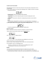
Control action (Gr.4)
Range:
rEv = reverse action
dir = direct action
REVERSE ACTION
DIRECT ACTION
Input
Input
Output
Output
NOTE: when device is configured with two control outputs or the first part of the
SMART algorithm (TUNE) is in progress the control action can be monitored
only.
Group 4 default data loading
Range:
OFF = No loading data
ON
= loading data
27/48
Run time group 5
AUXILIARY CONTROL PARAMETERS
Main control output low limit (Gr.5)
This parameter is available when one output is configured as main control output.
Range: from 0 % (of the output span) to ñ.OLH.
Main control output high limit (Gr.5)
This parameter is available when one output is configured as main control output.
Range: from ñ.OLL to 100 % (of the output span).
Main control output max rate of rise (Gr.5)
This parameter is available when one output is configured as main control output.
Ranges: from 1 %/s to 25 %/s.
Above this value the display shows "Inr' meaning that no limit is imposed.
NOTE: the ramp function will be active even if device is configured for On/OFF
control.
Main output cycle time (Gr.5)
This parameter is available when one output is configured as main control output.
Range: from 1 to 200 s.
28/48
Secondary control output low limit (Gr.5)
This parameter is available when one output is configured as secondary control
output.
Range: from 0 % (of the output span) to S.OLH.
Secondary control output high limit (Gr.5)
This parameter is available when one output is configured as secondary control
output.
Range: from S.OLL to 100 % (of the output span).
Secondary control output max rate of rise (Gr.5)
This parameter is available when one output is configured as secondary control
output.
Ranges: from 1 %/s to 25 %/s.
Above this value the display shows "Inf" meaning that no limit is imposed.
NOTE: the ramp function will be active even if device is configured for On/OFF
control.
Secondary output cycle time (Gr.5)
This parameter is available when one output is configured as secondary control
output.
Range: from 1 to 200 s.
Set point low limit (Gr.5)
Range: from “ñ.ln.L” configuration parameter to “rH”.
NOTE: When "rL" is modified and the new value is higher than the SP (and/or
SP2) value, the SP (and/or SP2) value will be realigned to “rL”.
29/48
Set point high limit (Gr.5)
Range: from “rL” to “ñ.ln.L” configuration parameter.
NOTE: When “rL" is modified the new value is lower than the SP (and/or SP2)
value, the SP (and/or SP2) value will be realigned to “rH”.
Rate of change for positive set point variations (Gr.5)
Range: from 1 to 200 digits per minute.
Above this value the display shows “Inf” and the transfer will be a step change.
Rate of change for negative set point variations (Gr.5)
Range: from 1 to 200 digits per minutes.
Above this value the display shows “lnf” and the transfer will be a step change.
Time out for the 80ft start (Gr.5)
This parameter is available when at least one output is configured as control
output.
Range: from 1 to 540 min.
Above this value the display shows "InF” and the limiting action is always active.
NOTE: The tOL can be always modified and:
- if the new value is set from 1 to 540, it will be activated only at the next
instrument power up or when the instrument is reverted from the output power
off;
- if "InF" is set, it will be immediately activated.
Group 5 default data loading
Range:
OFF = No loading data
ON
= loading data
30/48
Run time group 6
ALARMS SETTING
Alarm 1 type (Gr.6)
This parameter is available only when OUT 1 is configured as alarm 1 output
(“O1.Fn” configuration parameter = “ALr.1”)
Range: Proc = Alarm on process variable
bAnd = Band alarm on process variable
dEV = Deviation alarm on process variable
NOTE: When alarm type has been changed the alarm threshold will be forced to
its default value and alarm status will be deleted.
Alarm 1 configuration (Gr.6)
This parameter is available only when OUT 1 is configured as alarm 1 output
(“O1.Fn” configuration parameter = “ALr.1")
Range:
H.A.
= High alarm (outside band) with automatic reset
L.A.
= Low alarm (inside band) with automatic reset
H.A.Ac = High alarm (outside band) with automatic reset and
acknowledge
LA.Ac
= Low alarm (inside band) with automatic reset and
acknowledge
H.L.
= High alarm (outside band) with manual reset
L.L.
= Low alarm (inside band) with manual reset
NOTE: When alarm configuration has been changed, the alarm status will be
deleted.
31/48
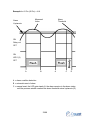
Example for A1.Cn (A2.Cn) = H.A.
Alarm
Threshold
Measured
Value
Alarm
Hysteresis
ON
Relay out
OFF
ON
LED 1(2)
OFF
A
B
A
C
D
A = alarm condition detection
B = automatic reset of alarm
C = manual reset; the LED gets steady lit, the alarm remains in the alarm status
until the process variable reaches the alarm threshold minus hysteresis (D).
32/48
Example for A 1.Cn (A2.Cn) = H.A.A.c
Alarm
Threshold
Measured
Value
Alarm
Hysteresis
ON
Relay out
OFF
ON
LED 1(2)
OFF
A
B
A
C
D
A = alarm condition detection
B = automatic reset of alarm
C = manual reset; the LED gets steady lit, the relay output goes OFF but the
LED remains steady lit until the process variable reaches the alarm
threshold minus hysteresis (D).
33/48
Example for A1.Cn (A2.Cn) = H.L
Alarm
Threshold
Measured
Value
Alarm
Hysteresis
ON
Relay out
OFF
ON
LED 1(2)
OFF
A
B
C
A
E
D
A = alarm condition detection
B = the alarm remains in alarm status (even if the measured value is under the
threshold) until a manual reset is performed (C).
E = if a manual reset is performed when the alarm condition still exist; the LED
gets steady lit, the alarm remains in the alarm status until the process
variable reaches the alarm threshold minus hysteresis (D).
34/48
Alarm 1 action (Gr.6)
This parameter is available only when OUT 1 is configured as alarm 1 output
(“01.Fn" configuration parameter = “ALr.1”)
Range:
dir
= direct action (Relay energized or SSr=1 in alarm condition)
rEV = Reverse action (Relay energized or SSr=1 in non alarm
condition)
Alarm 1 stand by (mask) function (Gr.6)
This parameter is available only when OUT 1 is configured as alarm 1 output
(“01.Fn” configuration parameter = “ALr.1”)
Range:
OFF = Stand-by function disabled
On
= Stand-by function enabled
NOTES:
1) If the alarm is programmed as band or deviation alarm, this function masks
the alarm condition after a set point change or at the instrument start-up until
process variable reaches the alarm threshold plus or minus hysteresis. If the
alarm is programmed as a process alarm, this function masks the alarm
condition at instrument start-up until process variable reaches the alarm
threshold plus or minus hysteresis.
2) The change from On to OFF has immediate effect, while the change from
OFF to On has effect at the next start up or set point change.
Alarm 2 type (Gr.6)
This parameter is available only when OUT 2 is configured as alarm 2 output
("02.Fn” configuration parameter = “ALr.2”)
Range: Proc = Alarm on process variable
bAnd = Band alarm on process variable
dEV = Deviation alarm on process variable
NOTE: When alarm type has been changed the alarm threshold will be forced to
its default value and alarm status will be deleted.
35/48
Alarm 2 configuration (Gr.6)
This parameter is available only when OUT 2 is configured as alarm 2 output
(“O2.Fn” configuration parameter = “ALr.2”)
Range:
H.A.
= High alarm (outside band) with automatic reset.
LA.
= Low alarm (inside band) with automatic reset.
H.A.Ac = High alarm (outside band) with automatic reset and
acknowledge.
LA.Ac
= Low alarm (inside band) with automatic reset and
acknowledge.
H.L
= High alarm (outside band) with manual reset
LL
= Low alarm (inside band) with manual reset
NOTE: When alarm configuration has been changed, the alarm status will be
deleted.
Alarm 2 action (Gr.6)
This parameter is available only when OUT 2 is configured as alarm 2 output
(.02.Fn. configuration parameter = .ALr.2.)
Range:
dir
= direct action (Relay energized or SSr=1 in alarm condition)
REV = Reverse action (Relay energized or SSr=1 in non alarm
condition)
Alarm 2 stand by (mask) function (Gr.6)
This parameter is available only when OUT 2 is configured as alarm 2 output
("02.Fn” configuration parameter = “ALr.2")
Range: OFF = Stand-by function disabled
On = Stand-by function enabled
NOTES:
1) If the alarm is programmed as band or deviation alarm, this function masks
the alarm condition after a set point change or at the instrument start-up until
process variable reaches the alarm threshold plus or minus hysteresis. If the
alarm is programmed as a process alarm, this function masks the alarm
condition at instrument start-up until process variable reaches the alarm
threshold plus or minus hysteresis.
36/48
2) The change from On to OFF has immediate effect, while the change from
OFF to On has effect at the next start up or set point change.
Loop break alarm configuration (Gr.6)
This parameter is available only when the LBA is configured (“L.b.AL”
configuration parameter is different from “nonE”)
Range:
A.
= Alarm with automatic reset.
A.Ac = Alarm with automatic reset and acknowledge.
L.
= Alarm with manual reset
Loop break alarm action (Gr.6)
This parameter is available only when the LBA is configured ("L.b.AL"
configuration parameter is different from “nonE”)
Range: dir = direct action (Relay energized or SSr=1 in alarm condition).
rEV = Reverse action (Relay energized or SSr=1 in non alarm condition).
NOTE: if the LBA is ored with AL 1 or AL2, this parameter can be monitored only
but not modified. The action type will be the same as selected for AL1 or AL2.
Group 6 default data loading
Range: OFF = No loading data
ON = loading data
37/48
Run time group dF
DEFAULT RUN TIME PARAMETERS LOADING
Available if SMART function is disabled.
Default run time parameters loading
Range:
OFF = No loading data
ON = loading data
Run time group Hidden
HIDDEN PARAMETERS - SMART LIMITS
This group is not normally accessible scrolling through the run time parameter
groups.
It is possible to enter in this group from every group (when Gr.1 or Gr.2 etc.. is
displayed), by keeping depressed the ▼ + FUNC keys for 4 seconds.
Minimum value of proportional band calculated by SMART
algorithm (Gr.Hd)
This parameter is available only when SMART function is configured (“Sñ.Fn"
configuration parameter is equal to "Enb").
Range: From 2.0% to "Pb.Hi".
NOTE: The "Pb.Lo" resolution will be equal to 0.1% up to 10.0% and 1% up to
100.0%.
Maximum value of proportional band calculated by SMART
algorithm (Gr.Hd)
This parameter is available only when SMART function is configured ("Sñ.Fn"
configuration parameter is equal to "Enb”).
Range: from "Pb.Lo" to 100.0%
NOTE: The "Pb.Hi" resolution will be equal to 0.1 % up to 10:0% and 1% up to
100.0%.
38/48
Minimum value of integral time calculated by SMART
algorithm. (Gr.Hd)
This parameter is available only when SMART function is configured ("Sñ.Fn"
configuration parameter is equal to “Enb”).
Range: from 00.01 mm.ss to “ti.Hi".
Maximum value of Integral time calculated by SMART
algorithm (Gr.Hd)
This parameter is available only when SMART function is configured ("Sñ.Fn”
configuration parameter is equal to "Enb").
Range: from "ti.Lo" to 20.00 mm.ss
Relative gain of the secondary output calculated by
SMART algorithm (Gr.Hd)
This parameter is available only when SMART function is configured ("Sn.Fn"
configuration parameter is equal to “Enb") and the secondary control output is
configured.
Range: OFF = Smart algorithm does not calculate "r.Gn" value.
On = Smart algorithm calculates “r.Gn” value.
Hidden group default data loading (Gr.Hd)
Range:
OFF = No loading data
ON = loading data
39/48
OUTPUT POWER OFF FUNCTION
This function allows to disable the control output when the instrument is in
“normal display mode” or when an “alternative display function” is shown.
In this open loop mode all control outputs will be in the OFF state and the alarms
will be in non alarm condition, the instrument will function as an indicator,
showing on the display the measured value.
It is possible to disable the control output by:
-
pressing the REV key for more than 4 s or
-
setting to OFF the “Cntr” run time parameter Gr. 2
During the output power off all the display functions (normal display mode and
alternative functions of the display) are available but the display will show “OFF”
if the control output value is required.
At power up, the control output will remain disabled if a power down is occurred.
It is possible to restore the control outputs by:
-
pressing the REV key for more than 4 seconds or
-
setting to ON the “Cntr” run time parameter Gr.2
When the control output is restored all the instrument functions will be activated
as for a power up.
NOTE: if the run time parameter Gr. 2 (which encompasses the “Cntr”
parameter) is software protected the REV pressure has no effect.
In this case the control output may be enabled or disabled by setting the “Cntr”
parameter only.
SP - SP2 SELECTION
By setting the “SP.SL” (Set point selection) run time parameter it is possible to
select the operating set point between SP and SP2.
The “SP.SL” parameter will be available only if the “AV.Sp” (Set point available)
configuration parameter is set to 2, otherwise will be available SP only.
DIRECT ACCESS TO THE SET POINT
When the device is in run time mode, it is possible to quickly modify the selected
operative set point value. Pushing the ▲ or ▼ key for more than 2 seconds, the
selected set point value will be displayed (the decimal point on the right of the
least significant digit is lit) and it will start to change.
The new set point value will be operative since no key is depressed for more
than 2 s, the previous indication will be displayed.
The direct access of the set point is disabled if all the run time parameter groups
are protected.
40/48
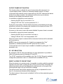
LAMP TEST
When it is desired to verify the display efficiency, push the FUNC key for more
than 4 seconds.
The instrument will turn ON, with a 50% duty cycle, all the LEDs of the display
(we define this function “LAMP TEST”).
During the LAMP TEST the instrument continues to control the process.
No time out is applied to the LAMP TEST.
Push any key when it is desired to come back to the previous indication.
LOOP BREAK ALARM (LBA function)
The functioning principle of this alarm is based on the concept that, with a steady
load and steady power output, the process rate of rise (deviation/time) is steady
as well. Thus, analyzing the process rate of rise of the limit conditions set by the
following parameters:
"ñ.OLL" and " ñ.OLH" for heating or
"S.OLL" and "S.OLH" for cooling or
" ñ.OLL" and "S.OLH" for heating/cooling),
it is possible to estimate the two limits which define the correct process behavior.
The LBA function is automatically activated when the control algorithm requires
the maximum or the minimum power.
If the process response is slower than the estimated limits, the instrument
generates the "L.b.AL" (AL flashing) alarm indication in order to show that one or
more element of the control loop is in fault condition.
It is possible to acknowledge the LBA alarm by setting " ñ.rst" (manual reset of
alarm - Gr. 3 - run time parameter) to ON and then pushing the FUNC key; the
indication displayed prior to the alarm condition will be shown again. The alarm
acknowledgement status "L.b.AL" (with AL steady) may be displayed by pushing
the FUNC key once, when the instrument is in normal display mode.
Deviation: from 0 to 500 units
Time: from 1 second to 40 minutes
Hysteresis: from 1% to 50% of the power output
NOTES:
1) The LBA does not operate during the soft start.
2) The LBA function can work even when the instrument operates with the
SMART function.
41/48
SMART FUNCTION
It is used to automatically optimize the control action.
To enable the SMART function proceed as follows:
1) push the ▼ + FUNC keys until "Gr. 2" run time parameter group is shown.
2) push the FUNC key until "Sñrt" parameter is shown.
3) push ▲ or ▼ and set the "On" indication on the display;
4) push the FUNC key.
The ST LED is flashing during the first part of the SMART algorithm (TUNE),
while it is steady lit during the second part (ADAPTIVE).
When the smart function is enabled, it is possible to display but not to modify the
control parameters.
To disable the SMART function proceed as follows:
1) push the ▼ + FUNC keys until "Gr. 2" run time parameter group is shown.
2) push the FUNC key until "Sñrt" parameter is shown.
3) push ▲ or ▼ and set the "OFF" indication on the display;
4) push the FUNC key.
The ST LED will turn off.
The instrument maintains the current set of control parameters and it enables
parameter modification.
NOTES:
1) the SMART function cannot be activated when: - the ON/OFF control is
programmed (Pb=O);
-
the control output is disabled
-
the SMART function is not configured.
2) The SMART enabling/disabling can be protected by safety key.
42/48
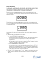
ERROR MESSAGES
OVERRANGE, UNDERRANGE AND SENSOR LEADS BREAK INDICATIONS
This instrument is capable to detect a fault on the process variable
(OVERRANGE or UNDERRANGE or SENSOR LEADS BREAK).
When the process variable exceeds the full scale value programmed by the
"ñ.ln.t” parameter, an OVERRANGE condition occur and it will be shown on the
display as follows:
When the process variable is lower than the initial scale value programmed by
the “ñ.ln.t” parameter, an UNDERRANGE condition occur and it will be shown on
the display as follows:
In presence of an input out-of-range condition, the control outputs operate as
follows:
a) When the "SF.Cn" parameter is set to "Std.":
a. 1 ) An OVERRANGE is detected and
- the instrument is set for one control output only, the output will be forced
to 0 (if reverse action is programmed) or to 100% (if direct action is
programmed).
- the instrument is set for two control outputs, the "Main" output is forced to
0 and the "Secondary" output is forced to 100%.
a. 2) An UNDERRANGE is detected and
- the instrument is set for one output only, the output is forced to 100 % (if
reverse action is programmed) or to 0 % (if direct action is programmed).
- the instrument is set for two control outputs, the "Main" output is forced to
100% and the "Secondary" output is forced to O.
b) With the “SF.Cn” parameter set to “Ov.Un”, when an over-range or an underrange condition is detected, the power output is forced to the safety value
“SF.UL”.
43/48
c) When the “SF.Cn” parameter is set to “OvEr"
c. 1) if an over-range condition is detected, the power output is forced to the
safety value “SF.UL”.
c. 2) if an under-range condition is detected the instrument will operate as
described at point a.2).
d) When the “SF.Cn” parameter is set to “Undr”
d. 1) if an under-range condition is detected, the power output is forced to
the safety value RSF.ULR.
d. 2) if an over-range condition is detected the instrument will operate as
described at point a.1).
This instrument is capable to detect the sensor leads break condition.
When the sensor leads break condition is detected, the instrument shows:
Note: On the linear input the leads break can be detected only for 12-60 mV
range.
In addition, on RTD input a special test is provided to signal
when input resistance is less than 12 Q (Short circuit sensor detection).
The instrument is also capable to detect a reference junction measurement error
(E.502) and on the internal auto-zero (E.500).
When a fault condition different from over-range or under-range is detected,
alarms and control output will operate as in presence of an over-range condition.
ERROR MESSAGES
At the end of the configuration parameters modification, the instrument checks
the new parameter values.
At instrument start up in run time mode, all the parameters are checked.
44/48
If an error is detected on a run time parameter group (for ex. group 5), the
instrument will show:
If an error is detected on configuration parameters, the instrument will show:
The Instrument resets Itself automatically after a 6 second time out.
When one of these errors Is detected, following the procedures described for
standard parameter modification, achieve the group with the wrong parameter
setting and correct it (every keystroke resets the time out. The time out Is
disabled when modify configuration parameters mode is enabled).
When the error is corrected push the “▼ + FUNC” keys until the Instrument
resets (if in run mode) or end the modify configuration parameters mode
following the normal procedure.
Repeat the above, described procedure if another error is shown.
The instrument is also capable of detecting the following errors:
E.100
Error during data saving in EAROM
E.120
Error on control parameters calculated by SMART when the control
action was changed from PI to PID or vlceversa.
E.130
Error during SMART, the algorithm Is notable to calculate correctly the
control parameters. The instrument will be forced to work as PI
controller.
E.140
Error when control parameters calculated by SMART are out of range of
the values set in the Hidden group.
Note: push any key to delete E.130 or E.140 indication.
E.500
Error during auto-zero measurement
E.502
Error during reference junction measurement.
Note: this error may be generated by an ambient temperature higher
than 70 °C (158 °F) or lower than -20 °C (-4 °F).
E.510
Error during calibration procedure
When one of these errors Is detected, contact your supplier.
45/48
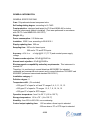
GENERAL INFORMATION
GENERAL SPECIFICATIONS
Case: Polycarbonate brown transparent color.
Self-extinguishing degree: according to UL 746C.
Front protection - designed and tested for IP 65 and NEMA 4X for indoor
locations (when panel gasket is installed). (Test were performed in accordance
with CEI 70-1 and NEMA 250-1991 STD)
Weight: 90 g
Power consumption: 2.5 Watts max.
Insulation: 2300 V rms, according to EN 61010-1
Display updating time: 500 ms
Sampling time: 250 ms for linear inputs
500 ms for TC and RTD Inputs.
Accuracy: ±2% f.s.v.
voltage
±1 digit @ 25 °C (77 °F) and nominal power supply
Common mode rejection: 120 dB @ 50/60 Hz.
Normal mode rejectlon: 60 dB @ 50/60Hz.
Electromagnetic compatibility and safety requirements: This instrument is
marked CE.
Therefore, it is conforming to council directives 89/336/EEC for industrial
residential and commercial environment and to council directives 73/23/EEC and
93/68/EEC (reference harmonized standard EN 61010-1).
Installation category: II
Pollution degree: 2
Temperature drift: (CJ excluded)
< 200 ppm/°C of span for mV and TC ranges 3, 4, 5, 11, 12, 13.
< 250 ppm/°C of span for TC ranges 1,2, 5, 7, 9, 10, 14, 15.
< 500 ppm/°C of span for RTD ranges.
Operative temperature: from 0 to 50 °C (+32 to 122 °F).
Storage temperature: -20 to +70 ° (-4 to 158 °F)
Humidity: from 20% to 85% RH, non-condensing.
Control output updating time:
-250 ms when a linear input is selected
-500 ms when a TC or RTD Input is selected.
46/48
Programming Example
Temperature monitor with alarm set points for low limit and high limit.
The CTD 24 controller is not directly controlling the heater or device that is
changing the temperature. It is monitoring the temperatures and will activate one
of 2 alarms if the temperature goes below or above the set operating range of 20
to 40 degrees Celsius (°C).
Since the CTD24 is monitoring the temperature, the configuration and parameter
control functions are not necessary. The main requirements are to set the
temperature input device and the output functions.
I. Configuration Parameters
1.
Input type:
11
-type K thermocouple
2.
low limit scale value:
-150
-default value
3.
high limit scale value:
2500
-default value
4.
input offset adjustment: 0
-default value
5.
output 1 function:
Alr.1
-alarm 1 output
6.
output 2 function:
Alr.2
-alarm 2 output
7.
set point indication:
Fn.SP - default value
8.
set point available:
1
9.
-only main set point
All remaining functions can be left at the default settings.
10. Security codes can be activated at the user’s discretion.
II. Run Timer Parameters
1.
Set point values
2.
Alarm threshold and hysteresis value
a.
-can be set but not necessary
manual rest of alarms OFF
47/48
b.
alarm 1 threshold
20
-low temperature limit
c.
alarm 2 threshold
40
-high temperature limit
d.
alarm 1 hysteresis
1
-low temperature limit
e.
alarm 2 hysteresis
1
-high temperature limit
3.
Alarm settings
a.
alarm 1 type
Proc
-alarm on threshold
b.
alarm 1 config
L.A.
-low alarm
c.
alarm 1 action
dir
-direct action
d.
alarm 1 stand by
OFF
-stand-by disabled
e.
alarm 2 type
Proc
-alarm on threshold
f.
alarm 2 config
H.A.
-high alarm
g.
alarm 2 action
dir
-direct action
h.
alarm 2 stand by
OFF
-stand-by disabled
48/48