1
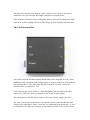
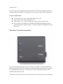
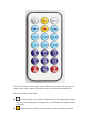
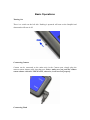
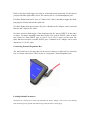
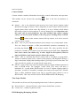
MJKZZ SnapPal User Manual Components The SnapPal has many configuration options and each option has its own component. The Main Unit The main unit contains some built-in sensors and two ports, one port for camera connection, one port for input and output connection to extension box. It has a built-in 350mah Li-Poly rechargeable battery and it can be charged via USB mini cable. It takes roughly 2 hours to fully charge up from complete depleted state. The I/O Extension Box This is the extension box that expands functionality of the SnapPal. A 4 pin 3.5mm headphone cable (included in all configurations) is used to connect the main unit and this extension box. On the main unit, the port is marked “I/O Port” and on the extension box, it is marked as “I/O” It also has two input ports, both are 3.5mm headphone jack and marked X and Y respectively. These two ports corresponds to the X and Y input signals. This extension box also has power jack to will accept a power supply up to 24V. The “Out” port on the extension box is a controlled power outlet that has the same voltage as the input from “Power” jack, but it is controlled by the main unit -- it will be switched on or off by the main unit. It is normally used for a valve used in water drop function. The “5V” port is an output port and is regulated 5V with 30ma capability. Again, it is controlled by the main unit. Commonly, you can connect a laser pointer to this port. Usage Considerations: Do not connect a power with voltage higher than 24V Max current “Out” port can handle is 2A Max current “5V” is 30ma, enough for a laser pointer but not others Never short circuit either port and that will definitely damage this ports -typical symptom is shorted output -- the ports can not be switched off by the main unit The Motor Control Extension Box This is the extension box that is used to control a step motor. The step motor driver board is replaceable. This driver board is commonly found and used with 3D printer. It is configured to operate at 1/16 microstep. For more information, please read manual for this driver board. This motor control extension box can communicate with the main unit via 4 segment 3.5mm headphone jack cable -- the I/O Port on the main unit and the I/O port on this extension box. There are also two 3.5mm headphone jacks on this unit marked as X and Y. These two ports corresponds to the X and Y input signals when this extension box is used in functionality other than motor control. But when it is used for motor control, these two ports can be used as limit switch input -- when either X or Y input is shorted (making contact or at very low resistance), the motor is STOPPED. The port marked as “Motor” connects to a step motor and pin arrangement is A+ AB+ B-. But different step motor has different winding, so motor movement direction might be different, it is up to user to find out. In case of limit stop switch when using X and Y, it is up to user to individually short the switch to find out which port (X or Y) controls which direction. The port marked as “Power” is used to connect power supply for motor control. Max rating on power supply is 15V even though the driver board can take up higher voltage. This is because the control circuit can only take up 15V. Usage Considerations: Do not exceed 15V for power supply The X and Y inputs are used as limit switch when used as step motor control Make sure X and Y are not shorted, else step motor will NOT move Try to short X or Y to find out which is controlling which direction of motor The Remote Control The SnapPal is operated with a remote control. There are two identical remote controls for each unit, one is back up in case the other is lost. There are 21 buttons on the remote control. When screen is turned off, any press of button on the remote control will turn the screen on without doing anything else. Here are meaning of each button: button is used to access Camera Module directly with single push of button. It is only active during non-executing mode, ie, the SnapPal is waiting for input of remote. button is used to confirm a menu selection or start executing a particular module within that module’s menu. button is to stop a module in executing mode. For example, it can be used to stop press-and-hold function in Bulb operation in Camera Module. button is used to exit out of a particular module menu and return back to Main menu. It can also be used to stop the execution of a module. and are used to navigate main menu selection or menu item selection within a module menu. and are used to decrease or increase most values by one. For other modules, they have their own meaning. For example, for External Input module, it can be used to change edge selection instead of value. and are used to decrease or increase value by 10 for most values. But for some particular entries, it has its own meaning, please refer to individual entry in different modules. button is used to access Lightning module directly from main menu with single push of button. It has no effect outside main menu. button is used to access Sound module directly from main menu with single push of button. button is used to access Light detection module directly from the main menu with single push of button. button is used to access Timelapse module directly from the main menu with single push of button. button is used to access Step Motor control module directly from the main menu with single push of button. button is used to access External control module directly from the main menu with single push of button. button is used to access Water Drop module directly from the main menu with single push of button. button is used to load parameters previously saved. If this button is used within a module, only data for that module will be loaded back. If it is used in Main menu, all data will be loaded back. button is used to save parameters. If this button is used within a module, only data for that module will be saved. If it is used in Main menu, data for all modules will be saved. Basic Operations Turning On There is a switch on the left side. Pushing it upwards will turn on the SnapPal and downwards will turn it off. Connecting Camera Camera can be connected to the main unit via the Camera port, simply plug the camera remote shutter cable into that port. Notice: make sure you push the camera remote shutter cable ALL THE WAY IN, otherwise, it will not work properly. Connecting Flash Flash or wireless flash trigger can also be connected tot the main unit via the camera port provided the right cable is used. The camera port is a 2.5mm headphone jack. For those flashes that has PC port, a 2.5mm-to-PC cable is needed to trigger the flash, just plug the 2.5mm end into the main unit For those flashes that does not have PC port, a Hotshoe-to-PC adapter can be used and then use the 2.5mm-to-PC cable. For those wireless flash trigger, if the transmitter has PC port as INPUT, do the same as above. For those transmitter that does not have PC port as INPUT, some of them has 2.5mm or 3.5mm INPUT port, a 2.5-to-2.5 or 2.5-to-3.5 stereo can be used. For those that does not have external INPUT port, a Hotshoe-to-PC adapter can be used and the use 2.5-to-PC cable. Connecting External Expansion Box The main unit has an I/O port that can be used to connect to either an I/O extension box or a motor control box. This I/O port is a 4 segment 3.5mm headphone jack. Loading Default Parameters Sometimes it is necessary to restore all parameters to factory settings. You can do so by shorting both X and Y input to ground (the bottom ring of the extension 3.5mm plug). Software Modules Camera Module Camera module contains information about basic camera information and operation. This module can be accessed by pressing Here is the list of parameter or selections: Shutter -- this is the parameter that specifies how long camera tripping signal should last to trigger a camera. This is important as some camera does not react to signals shorter than certain value. By default, it is set to 200ms which almost universally works for most cameras. It can be changed by user. Important note: this value will be used globally by any other modules that require tripping camera, such as all sensor modules, water drop, focus stacking (motor control). Pressing button on the remote control will trip camera, so it can be used as camera remote control. Bulb -- this is a press-and-hold function when camera is set to bulb shutter mode. You can always terminate a bulb press-and-hold operation prematurely by pressing stop button on the remote control. The value specified for this parameter is number of seconds to keep the shutter open in bulb mode. Important note: most camera has shutter lag, so there might be discrepancies between time specified here and actual exposure time by the camera. Selfie -- this is a function that can be used to take a self photo or group photo. Almost all modern camera have a timer for this purpose, but SnapPal will have a large count down display that remind people to get ready to pose for the shot. The value specified is number of seconds for the count down. Min B -- some camera can only keep shutter open for certain minimum amount of time in BULB mode. For example, Canon 550D (T2i) series will have a minimum of 1 second under BULB mode. So even if camera tripping signal is less than 1 second (0.5 second for example), the camera will expose for 1 second. This is where minimum shutter open time is specified when camera is set to BULB mode. This value will be used for BULB HDR and BULB Ramping. Time Lapse Module This module can be accessed by navigating main menu. It has two parameters: Interval (Intvl) -- this specifies how often camera should take a picture. Count (Cnt) -- number of photos to take. BULB Ramping (Bramping) Module SnapPal supports BULB mode exposure ramping, a technique that exposure is increased or descreased during time lapse. For example, during sunset or sunrise, it is a good idea to increase or decrease exposure as time passes by. SnapPal can do this by adjusting exposure time when the camera is set at BULB mode. It has the following parameters: Type -- this is to specify how exposure is adjusted -- linearly or logarithmicaly. By linear, the exposure time is increased or decreased by dividing the difference between start exposure time and end exposure time by number of photos (ie, count parameter below). On the other hand, the logarithm method increase or decrease exposure time by dividing the log of difference between start exposure time and end exposure time and convert it back to numeric value. The linear method is simple straight forward one, the logarithm method requires some calculation and experience in estimating start and end exposure time. Start Exposure Time (S Tv) -- this is the start exposure time in seconds End Exposure Time (E Tv) -- this is the end exposure time in seconds Interval (Intvl) -- this is how often a photo is taken in seconds Count (Cnt) -- number of photos to take. Bramping requires a lot of experience to get it right. But one tip is to use an ND filter so that BULB mode can be used. BULB HDR Module HDR (High Dynamic Range) technique is used to collect a number of photos under different exposure and then combine them into one photo that has details in both high light area and dark area. Here are the parameters: Count (Cnt) -- number of photos to take Mid Tone (Mid) -- the middle exposure time in seconds. Step -- EV (exposure value) to increase for each photo Very important note: if the middle exposure is too small, it will result in time exposure less than the minimum bulb open time, when this happens, an “*” will show up. Lightning Module Lightning module uses internal built-in lightning sensor to detect lightning strike or any sudden light change. Upon detection, camera or flash will be triggered. Here are parameters for this module: Sensitivity Level (Level) -- this sets the sensitivity of the module. Due to high amplification at higher sensitivity level, technical limit of sensor used plays important role now -- variation of sensor construction within tolerance can cause sensitivity variation. SnapPal is built to the minimum variation of sensor specification. In this case, some sensor in particular SnapPal is more sensitive than the minimum, thus at high sensitivity level, it might oscillate. Therefore, it is not recommended to use sensitivity level higher than 28 where it is sensitive enough for most cases! Delay -- this value has NO meaning at all for lightning trigger because it is not desirable to have a delay. It is NOT editable. Hold -- Sometimes, it is better to stop sensing after detection to reduce oscillation or let camera settle down -- some camera is slow to save dark pictures. An important note: lightning module detects sudden increase of light, it does not responds to decrease of light. It does not responds to slow increase of light. Light Module Light module is essentially Lightning module with Delay parameter turned on. It will responds to sudden increase of light condition but with delay to trigger camera. The delay parameter of this module represents amount of time to wait until trigger camera or flash. This cam be used to capture a particular moment of an event. Important note, as with Lightning module, this module detects increase of light condition, not decrease. Therefore, if a laser is used to shine on this sensor and trying to detect an object breaking the laser beam, it will only trigger after the object passes the beam, NOT at the moment it breaks the beam! Sound Module Sound module is designed to detect sound using its internal sound sensor. It has following parameters: Sensitivity Level (Level) -- this is used to adjust sensitivity level of sound module. Again, due to high amplification level, it is not recommended to set this parameter larger than 28. Delay -- amount of time to wait until triggering the camera. This is used to capture particular moment of interest. Hold -- amount of time to turn off the sensor before activating it. This is required to eliminate cyclic trigger. For example, if a sound is detected and the camera is triggered, the sound of camera shutter might trigger sound detection again if Hold time is too small, thus creating a cyclic triggering situation. External Input Module This module allows edge detection on two inputs X and Y. These two inputs are the two inputs on both the I/O Extension Box and Motor Control Extension box. Both are normally HIGH. Parameters for External Module: Edges -- this module can detect edge UP (signal change from LOW to HIGH), edge DOWN (signal change from HIGH to LOW), or BOTH (any signal change). Using to change X value and to change Y value (XY) Delay -- amount of time to wait until triggering camera/flash Hold -- amount of time to wait until activate sensor again. A laser detection sensor unit can be plugged into either X or Y (or both if you have two such sensor). This laser detection module keeps the X or Y signal LOW when plugged and has laser shined on it. Upon interruption of laser beam shining on the laser sensor, it will create an UP edge signal on the port plugged in, so an UP detection must be specified when using laser detection sensor. Having said above, if the supplied laser pointer is plugged into the I/O extension box’t 5V port, when either X or Y edge are set to detect UP condition, the 5V port will be activated, thus turning on the laser. This is the ONLY situation that the external laser is turned on and off upon detection-- UP edge detection. This reason for this is to avoid cyclic triggering. Another important note: battery must be well charged (80% or more) for SnapPal to turn on the external 5V port or the Out port on the I/O Extension Box, otherwise, it might not work. Multi-Sensor Module This module allows combination of a set of sensors and input modules to trigger camera or flash. By using the +1, +10, +100 to change to Y, Or use -1, -10, -100 to change to N for each entry of sensor or module. This capability of SnapPal make it a versatile tool. Important Notes: Light sensor and Sound sensor uses the same circuitry for sensitivity therefore sensitivity level can be set in either light module or sound module. Value for X and Y input can be N (not active) or one of the edge trigger values -Rising, Falling, or Both. If XnY input is set to Y, then both X and Y must satisfy their triggering condition to trigger camera or flash. For example, if X is set to rising edge and Y is set to falling edge, the camera is trigger if and only if there is a rising edge on the X and a falling edge on the Y at SAME moment. This can be very useful for cross laser beam detection. Speed Capture Module Speed capture module allows SnapPal to capture amount of time between input X and Y being activated according to their edge detection settings. Note this time are measured in milliseconds with fraction in microseconds. One example is to use two laser sensors plugged into input X and Y, then use two laser pointers to shine on these two sensors. When an object passes through and interrupt both beams, then the time it took the object to do so will be measured. If distance of the two laser beams is known, the speed of the object can be calculated. Water Drop Module One of unique feature of SnapPal is its water drop module. This module controls an electrical valve connected to the Extension Box at precise moment and duration such that liquid can passes through the valve at precise sequence. When this sequence is designed precisely, collision will occur and it can be captured by a camera connected to SnapPal at precise moment. Here are parameters: Open: this is where duration of a valve kept open is specified. This value determines the drop size of liquid, the longer the duration, the larger the drop size. Important note: if the drop size is too large, the drop might be broken apart by gravity. Close: this is the duration a valve is kept closed. This parameter always follows the Open parameter. - Add - : this is the entry that a new value can be inserted. If the entry before it is Open, then a Close entry will be added if you press +1, +10, +100. If the entry before it is Close, an Open entry will be added if you press +1, +10, +100. The first entry added will always be an Open entry. Snap: this entry specifies when camera can should be triggered, it is independent of Open and Close entry, but it is the controlling factor -- when time reaches Snap value, all Open and Close entry will be terminated. More note on this. Important Notes: The Snap entry is the controlling one. When time reaches its value, camera is triggered and operation is terminated. For example, if all values of Open and Close add up to 600 and Snap is 400, them when time reaches 400, camera is triggered and open and close operations are terminated. When triggering a camera, please allow enough time for camera shutter lag. This is important because some camera has very LONG lag -- when camera is signaled to take a picture, it takes certain lag to do so. Step Motor Module Step Motor module is designed to drive a step motor through Step Motor control box. It is very useful in many situations where step motor is used to move a camera or other equipment. It has the following parameters Dir -- direction to move the step motor. It has two values Fwd and Bkwd. Press on the remote to change to Fwd and press to change it to Bkwd. Important note here: if you use your own step motor, depending how you wire your motor, the Fwd and Bkwd become relative, ie, no sure way to tell if it is really forward or backward direction. Dir -- when or is pressed, it will move the motor by Cnt*Steps*Unit amount forward or backward. This is useful to move motor freely. Dir -- when amount forward or backward. This is useful to move motor freely. Cnt -- number of photos to take Speed -- how fast do you want to drive the step motor Steps -- number of steps to move the step motor by “Unit” amount Delay -- how long to pause the motor between photos Unit -- number of pulses per “Step”. Each pulse will advance motor by one unit. or is pressed, it will move the motor by 2*Cnt*Steps*Unit