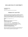
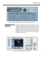
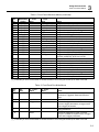
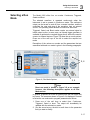
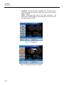
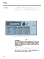
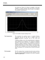
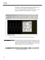
1
User Manual
Models 8101/8102
100 MHz Single / Dual
Function / Arbitrary Generators
Publication No. 0901013
Tabor Electronics Ltd.
Tabor Electronics Ltd.
P.O. Box 404, Tel Hanan Israel 20302
Tel: +972-4-821-3393, FAX: +972-4-821-3388
PUBLICATION DATE: January 13, 2009
Copyright 2005 by Tabor Electronics Ltd. Printed in Israel. All rights reserved. This book or parts thereof may
not be reproduced in any form without written permission of the publisher.
WARRANTY STATEMENT
Products sold by Tabor Electronics Ltd. are warranted to be free from defects in workmanship or materials.
Tabor Electronics Ltd. will, at its option, either repair or replace any hardware products which prove to be defective during the warranty period. You are a valued customer. Our mission is to make any necessary repairs
in a reliable and timely manner.
Duration of Warranty
The warranty period for this Tabor Electronics Ltd. hardware is three years, except software and firmware
products designed for use with Tabor Electronics Ltd. Hardware is warranted not to fail to execute its programming instructions due to defect in materials or workmanship for a period of ninety (90) days from the
date of delivery to the initial end user.
Return of Product
Authorization is required from Tabor Electronics before you send us your product for service or calibration.
Call your nearest Tabor Electronics support facility. If you are unsure where to call, contact Tabor Electronics
Ltd. Tel Hanan, Israel at 972-4-821-3393 or via fax at 972-4-821-3388. We can be reached at: [email protected]
Limitation of Warranty
Tabor Electronics Ltd. shall be released from all obligations under this warranty in the event repairs or modifications are made by persons other than authorized Tabor Electronics service personnel or without the written
consent of Tabor Electronics.
Tabor Electronics Ltd. expressly disclaims any liability to its customers, dealers and representatives and to
users of its product, and to any other person or persons, for special or consequential damages of any kind
and from any cause whatsoever arising out of or in any way connected with the manufacture, sale, handling,
repair, maintenance, replacement or use of said products.
Representations and warranties made by any person including dealers and representatives of Tabor Electronics Ltd., which are inconsistent or in conflict with the terms of this warranty (including but not limited to the
limitations of the liability of Tabor Electronics Ltd. as set forth above), shall not be binding upon Tabor Electronics Ltd. unless reduced to writing and approved by an officer of Tabor Electronics Ltd.
Except as stated above, Tabor Electronics Ltd. makes no warranty, express or implied (either in fact or by
operation of law), statutory or otherwise; and except to the extent stated above, Tabor Electronics Ltd. shall
have no liability under any warranty, express or implied (either in fact or by operation of law), statutory or otherwise.
PROPRIETARY NOTICE
This document and the technical data herein disclosed, are proprietary to Tabor Electronics, and shall not, without express
written permission of Tabor Electronics, be used, in whole or in part to solicit quotations from a competitive source or used
for manufacture by anyone other than Tabor Electronics. The information herein has been developed at private expense,
and may only be used for operation and maintenance reference purposes or for purposes of engineering evaluation and
incorporation into technical specifications and other documents, which specify procurement of products from Tabor Electronics.
FOR YOUR SAFETY
Before undertaking any troubleshooting, maintenance or exploratory procedure, read carefully the WARNINGS and CAUTION notices.
This equipment contains voltage hazardous to human life and safety, and is capable of inflicting personal injury.
If this instrument is to be powered from the AC line (mains) through an autotransformer,
ensure the common connector is connected to the neutral (earth pole) of the power supply.
Before operating the unit, ensure the conductor (green wire) is connected to the ground
(earth) conductor of the power outlet. Do not use a two-conductor extension cord or a
three-prong/two-prong adapter. This will defeat the protective feature of the third conductor
in the power cord.
Maintenance and calibration procedures sometimes call for operation of the unit with power
applied and protective covers removed. Read the procedures and heed warnings to avoid
“live” circuits points.
Before operation this instrument:
1. Ensure the instrument is configured to operate on the voltage at the power source. See
Installation Section.
2. Ensure the proper fuse is in place for the power source to operate.
3. Ensure all other devices connected to or in proximity to this instrument are properly
grounded or connected to the protective third-wire earth ground.
If the instrument:
-
fails to operate satisfactorily
shows visible damage
has been stored under unfavorable conditions
has sustained stress
Do not operate until performance is checked by qualified personnel.
DECLARATION OF CONFORMITY
We: Tabor Electronics Ltd.
9 Hatasia Street, Tel Hanan
ISRAEL 36888
declare, that the 100MHz Arbitrary Function Generators
Models 8101 and 8102
complies with the requirements of the Electro Magnetic Compatibility 89/336/EEC as
amended by 92/31/EEC, 93/68/EEC, 92/263/EEC and 93/97/EEC and the Low Voltage
Directive 73/23/EEC amended by 93/68/EEC, according to testing performed at
ORDOS/E.M.I TEST LABs (#5TBR964CX, Oct. 2005). Compliance was demonstrated to
the following specifications as listed in the official Journal of the European Communities:
Safety:
IEC/EN 61010-1 2nd Edition: 2001+ C1, C2
EMC:
EN55022:2001 Class A Radiated and Conducted Emission
IEC61000-3-2:2001(Am1) Harmonics
IEC61000-3-3:2002(Am1) Flickers
IEC61000-4-2:2001(Am1+Am2)
ESD : Contact Discharge ±4Kv
Air Discharge ±8Kv
IEC61000-4-3:2002(Am1) Radiated immunity - 3V/m (80MHz-1000MHz)
IEC61000-4-4:2001 (Am2) Electrical Fast Transient and Burst ±1.0kV, 5KHz
IEC61000-4-5:2001 (Am1) Surges DM ±1.0kV CM ±2.0Kv
IEC61000-4-6:2003 Current injection immunity - 3Vrms
IEC61000-4-8:2001 Magnetic field 1Amper
IEC61000-4-11:2001 Voltage dips and variation
Models 8101 and 8102 are built on the same platform and share specifications and
features except the 8101 is a single channel version and while the 8102 has two
channels. The tests were performed on a typical configuration.
Table of Contents
Chapter
1
Title
Page
Getting Started.................................................................................................................... 1-1
What’s in This Chapter....................................................................................................... 1-3
Introduction ........................................................................................................................ 1-3
8102 Feature Highlights ..................................................................................................... 1-3
ArbConnection Feature Highlights...................................................................................... 1-4
Introduction ........................................................................................................................ 1-6
Safety Considerations ........................................................................................................ 1-8
Supplied Accessories......................................................................................................... 1-8
Specifications..................................................................................................................... 1-8
Functional Description........................................................................................................ 1-9
Front Panel Connectors and Indicators .............................................................................. 1-9
Main Output - Channels 1 and 2 ................................................................................. 1-9
SYNC Output.............................................................................................................. 1-9
Front Panel Controls .......................................................................................................... 1-9
Rear Panel Input & Output Connectors .............................................................................. 1-12
TRIG IN ...................................................................................................................... 1-12
REF IN........................................................................................................................ 1-13
LAN ............................................................................................................................ 1-13
USB ............................................................................................................................ 1-13
GPIB........................................................................................................................... 1-13
AC LINE ..................................................................................................................... 1-13
AC FUSE.................................................................................................................... 1-13
i
8101/8102
User Manual
Run Modes ........................................................................................................................ 1-14
Continuous ........................................................................................................................ 1-14
Triggered ........................................................................................................................... 1-14
Burst .................................................................................................................................. 1-15
Gated................................................................................................................................. 1-15
Delayed Trigger ................................................................................................................. 1-15
Re-Trigger.......................................................................................................................... 1-15
Trigger Source ................................................................................................................... 1-16
External ............................................................................................................................. 1-17
Bus .................................................................................................................................... 1-17
Mixed ................................................................................................................................. 1-17
Output Type ....................................................................................................................... 1-18
Standard Waveforms ......................................................................................................... 1-18
Arbitrary Waveforms .......................................................................................................... 1-19
Modulated Waveforms ....................................................................................................... 1-21
Modulation Off ............................................................................................................ 1-22
AM.............................................................................................................................. 1-22
FM .............................................................................................................................. 1-22
FSK ............................................................................................................................ 1-22
PSK ............................................................................................................................ 1-23
Sweep ........................................................................................................................ 1-23
Modulation Run Modes ...................................................................................................... 1-23
Auxiliary Functions ............................................................................................................. 1-23
Digital Pulse Generator...................................................................................................... 1-23
Output State....................................................................................................................... 1-25
Customizing the Output Units............................................................................................. 1-25
Programming the Model 8102 ............................................................................................ 1-25
2
Configuring the Instrument .............................................................................................. 2-1
Installation Overview .......................................................................................................... 2-3
Unpacking and Initial Inspection......................................................................................... 2-3
Safety Precautions ............................................................................................................. 2-3
Performance Checks.......................................................................................................... 2-4
Power Requirements.......................................................................................................... 2-4
Grounding Requirements ................................................................................................... 2-4
Long Term Storage or Repackaging for Shipment ............................................................. 2-5
Preparation for Use ............................................................................................................ 2-5
Installation.......................................................................................................................... 2-5
Installing Software Utilities ................................................................................................. 2-6
Controlling the Instrument from Remote............................................................................. 2-6
ii
Contents (continued)
Connecting to a Remote interface ...................................................................................... 2-7
Selecting a Remote interface ............................................................................................. 2-7
GPIB Configuration......................................................................................................... 2-8
USB Configuration.......................................................................................................... 2-9
LAN Configuration .......................................................................................................... 2-15
Choosing a Static IP Address...................................................................................... 2-17
3
Using the Instrument ......................................................................................................... 3-1
Overview............................................................................................................................3-3
Inter-Channel Dependency ................................................................................................3-3
Inter-Channel Phase Dependency ............................................................................... 3-3
Output Termination ............................................................................................................3-3
Input / Output Protection ....................................................................................................3-4
Power On/Reset Defaults...................................................................................................3-4
Controlling the 8102 ...........................................................................................................3-6
8102 Front Panel Menus ....................................................................................................3-7
Enabling the Outputs........................................................................................................3-11
Selecting a Waveform Type .............................................................................................3-12
Changing the Output Frequency ......................................................................................3-13
Changing the Sample Clock Frequency ...........................................................................3-14
Programming the Amplitude and Offset............................................................................3-15
Selecting a Run Mode......................................................................................................3-17
Selecting the Modulation Run Modes ...............................................................................3-18
Triggered Mode .......................................................................................................... 3-18
Delayed Trigger .......................................................................................................... 3-19
Re-Trigger................................................................................................................... 3-19
Gated Mode ................................................................................................................ 3-20
Burst Mode ................................................................................................................. 3-21
Using the Manual Trigger .................................................................................................3-22
Using the SYNC Output ...................................................................................................3-22
Applying Filters ................................................................................................................3-23
Generating Standard Waveforms .....................................................................................3-24
Generating Arbitrary Waveforms ......................................................................................3-34
What Are Arbitrary Waveforms?................................................................................. 3-35
Generating Arbitrary Waveforms ................................................................................ 3-35
Generating Modulated Waveforms...................................................................................3-37
Off ............................................................................................................................... 3-38
iii
8101/8102
User Manual
AM............................................................................................................................... 3-39
FM............................................................................................................................... 3-41
FSK ............................................................................................................................. 3-42
PSK............................................................................................................................. 3-44
Sweep ......................................................................................................................... 3-46
Using the Auxiliary Functions ...........................................................................................3-47
Using the Digital Pulse Generator .............................................................................. 3-47
Pulse Generator Menus .......................................................................................... 3-50
Pulse Design Limitations..................................................................................................3-52
Understanding the Basics of Phase Offset between Channels.................................. 3-53
Adjusting Phase Offset for Standard Waveforms ................................................... 3-54
Adjusting Phase Offset for Arbitrary Waveforms .................................................... 3-56
Adjusting Phase Offset for Modulated Waveforms................................................. 3-56
Customizing the Output Units...........................................................................................3-56
Selecting the Horizontal Units .................................................................................... 3-56
Adjusting Load Impedance ......................................................................................... 3-57
Monitoring the Internal Temperature ................................................................................3-57
4
ArbConnection© ................................................................................................................. 4-1
What’s in This Chapter?.....................................................................................................4-3
Introduction to ArbConnection............................................................................................4-3
Installing ArbConnection ....................................................................................................4-3
Quitting ArbConnection................................................................................................. 4-4
For the New and Advanced Users................................................................................ 4-4
Conventions Used in This Manual................................................................................ 4-4
The Opening Screen ..........................................................................................................4-5
ArbConnection Features ....................................................................................................4-6
The Control Panels ............................................................................................................4-6
The Operation Panels................................................................................................... 4-8
Main .......................................................................................................................... 4-8
Standard.................................................................................................................. 4-10
Arbitrary................................................................................................................... 4-11
Using the Memory Partition Table .......................................................................... 4-13
Trigger..................................................................................................................... 4-15
The Modulation Panels ............................................................................................... 4-16
FM ........................................................................................................................... 4-17
AM ........................................................................................................................... 4-18
Sweep ..................................................................................................................... 4-19
FSK/PSK ................................................................................................................. 4-20
iv
Contents (continued)
The Auxiliary Pulse Generator Panels ....................................................................... 4-22
The System Panels..................................................................................................... 4-23
General/Filters......................................................................................................... 4-23
Calibration ............................................................................................................... 4-24
The Composers Panels .............................................................................................. 4-25
The Wave Composer .............................................................................................. 4-25
The Toolbar ................................................................................................................ 4-32
The Waveform Screen................................................................................................ 4-33
Generating Waveforms Using the Equation Editor ...........................................................4-34
Writing Equations........................................................................................................ 4-36
Equation Convention .................................................................................................. 4-37
Typing Equations ........................................................................................................ 4-38
Equation Samples....................................................................................................... 4-39
Combining Waveforms ............................................................................................... 4-43
The Pulse Composer .............................................................................................. 4-45
The Command Editor .......................................................................................................4-63
Logging SCPI Commands................................................................................................4-63
5
Remote Programming Reference...................................................................................... 5-1
What’s in This Chapter..................................................................................................... 5-3
Introduction to SCPI......................................................................................................... 5-3
Command Format.......................................................................................................... 5-4
Command Separator ..................................................................................................... 5-4
The MIN and MAX Parameters ..................................................................................... 5-5
Querying Parameter Setting .......................................................................................... 5-5
Query Response Format ............................................................................................... 5-5
SCPI Command Terminator .......................................................................................... 5-5
IEEE-STD-488.2 Common Commands......................................................................... 5-5
SCPI Parameter Type.................................................................................................... 5-6
Numeric Parameters .................................................................................................. 5-6
Discrete Parameters .................................................................................................. 5-6
Boolean Parameters .................................................................................................. 5-6
Arbitrary Block Parameters ........................................................................................ 5-6
Binary Block Parameters ........................................................................................... 5-7
SCPI Syntax and Styles................................................................................................... 5-7
Instrument Control Commands ........................................................................................ 5-14
Standard Waveforms Control Commands........................................................................ 5-21
Arbitrary Waveforms Control Commands......................................................................... 5-28
v
8101/8102
User Manual
Modulated Waveforms Control Commands...................................................................... 5-35
FM Modulation Programming ........................................................................................ 5-38
AM modulation Programming ........................................................................................ 5-41
Sweep Modulation Programming .................................................................................. 5-42
FSK Modulation Programming ...................................................................................... 5-45
PSK Modulation Programming ...................................................................................... 5-46
Run Mode Commands ..................................................................................................... 5-50
Auxiliary Commands........................................................................................................ 5-55
Digital Pulse Programming ............................................................................................ 5-56
System Commands ....................................................................................................... 5-61
IEEE-STD-488.2 Common Commands and Queries ....................................................... 5-66
The SCPI Status Registers............................................................................................ 5-67
The Status Byte Register (STB) .................................................................................... 5-67
Reading the Status Byte Register ............................................................................. 5-68
Clearing the Status Byte Register ............................................................................. 5-68
Service Request Enable Register (SRE) .................................................................. 5-70
Standard Event Status Register (ESR)...................................................................... 5-70
Standard Event Status Enable Register (ESE) ......................................................... 5-71
Error Messages ............................................................................................................... 5-72
6
Performance Checks.......................................................................................................... 6-1
What’s in This Chapter ............................................................................................................ 6-3
Performance Checks ............................................................................................................... 6-3
Environmental Conditions........................................................................................................ 6-3
Warm-up Period ................................................................................................................... 6-4
Initial Instrument Setting....................................................................................................... 6-4
Recommended Test Equipment .............................................................................................. 6-4
Test Procedures....................................................................................................................... 6-4
Frequency Accuracy ............................................................................................................ 6-4
Frequency Accuracy, Internal Reference......................................................................... 6-5
Frequency Accuracy, External 10MHz Reference........................................................... 6-5
Amplitude Accuracy ............................................................................................................. 6-6
Amplitude Accuracy, DAC Output .................................................................................... 6-6
Amplitude Accuracy, DDS Output .................................................................................... 6-6
Offset Accuracy .................................................................................................................... 6-7
Offset Accuracy, DAC Output........................................................................................... 6-7
Offset Accuracy, DDS Output........................................................................................... 6-8
Squarewave Characteristics ................................................................................................ 6-8
Squarewave Checks......................................................................................................... 6-8
Skew Between Channels ................................................................................................. 6-9
vi
Contents (continued)
Sinewave Characteristics..................................................................................................... 6-9
Sinewave Distortions, DAC Output ................................................................................ 6-10
Sinewave Spectral Purity, DAC Output.......................................................................... 6-10
Sinewave Spectral Purity, DDS Output.......................................................................... 6-11
Sinewave Flatness, DAC Output.................................................................................... 6-11
Sinewave Flatness, DDS Output.................................................................................... 6-12
Trigger operation Characteristics....................................................................................... 6-12
Trigger, Gate, and Burst Characteristics........................................................................ 6-13
Mixed Trigger Advance Test .......................................................................................... 6-13
Delayed Trigger Characteristics..................................................................................... 6-15
Re-trigger Characteristics............................................................................................... 6-16
Trigger Slope .................................................................................................................. 6-17
Trigger Level................................................................................................................... 6-17
Modulated Waveforms Characteristics .............................................................................. 6-18
FM - Standard Waveforms ............................................................................................. 6-18
Triggered FM - Standard Waveforms ............................................................................ 6-19
FM Burst - Standard Waveforms.................................................................................... 6-20
Gated FM - Standard Waveforms .................................................................................. 6-21
Re-triggered FM Bursts - Standard Waveforms ............................................................ 6-22
AM................................................................................................................................... 6-23
FSK ................................................................................................................................. 6-24
PSK ................................................................................................................................. 6-25
Sweep ............................................................................................................................. 6-26
SYNC Output operation ..................................................................................................... 6-27
SYNC Qualifier - Bit........................................................................................................ 6-27
SYNC Source ................................................................................................................. 6-27
Waveform Memory Operation............................................................................................ 6-29
Waveform memory ......................................................................................................... 6-29
Remote Interfaces .............................................................................................................. 6-29
GPIB Control................................................................................................................... 6-30
USB Control.................................................................................................................... 6-30
LAN Control .................................................................................................................... 6-31
7
Adjustments and Firmware Update .................................................................................. 7-1
hat’s in This Chapter ................................................................................................................ 7-3
Performance Checks ............................................................................................................... 7-3
Environmental Conditions........................................................................................................ 7-3
Warm-up Period ................................................................................................................... 7-3
Recommended Test Equipment .............................................................................................. 7-4
Adjustment Procedures ........................................................................................................... 7-4
vii
8101/8102
User Manual
Reference Oscillators Adjustments ......................................................................................... 7-6
Base Line Offset Adjustments.............................................................................................. 7-8
Offset Adjustments ............................................................................................................. 7-11
Amplitude Adjustments ...................................................................................................... 7-15
Pulse Response Adjustments ............................................................................................ 7-24
Flatness Adjustments......................................................................................................... 7-24
Base Line Offset Adjustments............................................................................................ 7-29
Offset Adjustments ............................................................................................................. 7-32
Amplitude Adjustments ...................................................................................................... 7-36
Pulse Response Adjustments ............................................................................................ 7-44
Flatness Adjustments......................................................................................................... 7-45
Updating 8102 Firmware.................................................................................................... 7-49
Appendices
A
Specifications ..................................................................................................................... A-1
viii
List of Tables
Chapter
Title
Page
1-1, Run Modes and Trigger Source Options Summary .............................................................. 1-15
1-2, Trigger Source Options Summary ........................................................................................ 1-16
2-1, Valid and Invalid IP Addresses for Subnet Mask 255.255.255.0 ....................................... 2-17
3-1, Default Conditions After Reset ............................................................................................ 3-5
3-2, Front Panel Waveform Menus............................................................................................. 3-8
3-3, Front Panel Run Mode Menus ............................................................................................ 3-9
3-4, Front Panel Utility and Output Menus................................................................................ 3-10
3-5, Front Panel Auxiliary Menus ............................................................................................. 3-10
5-1, Model 8102 SCPI Commands List Summary ...................................................................... 5-8
5-2, Instrument Control Commands Summary ......................................................................... 5-14
5-3, Instrument Control Commands Summary ......................................................................... 5-21
5-4, Arbitrary Waveforms Commands Summary ...................................................................... 5-29
5-5, Modulated Waveforms Commands ................................................................................... 5-35
5-6, Run Mode Commands ...................................................................................................... 5-50
5-7, Auxiliary Commands ......................................................................................................... 5-55
5-8, System Commands Summary........................................................................................... 5-61
6-1, Recommended Test Equipment.......................................................................................... 6-4
6-2, Frequency Accuracy ........................................................................................................... 6-5
6-3, Frequency Accuracy Using External 10 MHz Reference ..................................................... 6-5
6-4, Amplitude Accuracy, DAC output ........................................................................................ 6-6
6-5, Amplitude Accuracy, DDS output ........................................................................................ 6-7
ix
8101/8102
User Manual
6-6, Offset Accuracy, DAC Output .......................................................................................... 6-7
6-7, Offset Accuracy, DDS Output .......................................................................................... 6-8
6-8, Square wave Characteristics ........................................................................................... 6-9
6-9, Sinewave Distortion, DAC Output Tests ........................................................................ 6-10
6-10, Sinewave Spectral Purity, DAC Output Test ............................................................... 6-10
6-12, Sinewave Flatness, DAC Output Test ......................................................................... 6-12
6-13, Sinewave Flatness, DDS Output Test ......................................................................... 6-12
6-14, Trigger, gate, and burst Characteristics....................................................................... 6-13
6-15, Trigger Delay Tests ...................................................................................................... 6-15
6-16, Re-Trigger Delay Tests ................................................................................................ 6-16
7-1, Recommended calibration for Adjustments ..................................................................... 7-4
x
List of Figures
Chapter
Title
Page
1-1, Model 8102 ............................................................................................................................ 1-4
1-2, ArbConnection – The Control Panels ..................................................................................... 1-5
1-3, ArbConnection – The Wave Composer .................................................................................. 1-5
1-4, ArbConnection – The Pulse Composer .................................................................................. 1-6
1-5, 8102 Front Panel Controls ................................................................................................... 1-10
1-6, 8102 Rear Panel .................................................................................................................. 1-12
1-7, Typical 8102 Standard Waveforms Display.......................................................................... 1-19
1-8, ArbConnection Example - Typical Standard Waveforms Panel ............................................ 1-19
1-9, Typical 8102 Arbitrary Waveforms Display........................................................................... 1-20
1-10, ArbConnection Example – Typical Arbitrary Waveforms Panel .......................................... 1-21
1-11, Typical Modulated waveform Display ................................................................................. 1-21
1-12, ArbConnection Example – FM Modulation Panel ............................................................... 1-22
1-13, 8102 Digital Pulse Generator Menu Example..................................................................... 1-24
1-14, ArbConnection Digital Pulse Generator Panel Example ..................................................... 1-24
2-1, Selecting a Remote interface ................................................................................................. 2-8
2-2, GPIB Configuration Screen .................................................................................................... 2-9
2-3, USB Device Detected .......................................................................................................... 2-10
2-4, Found New Hardware Wizard .............................................................................................. 2-10
2-5, Choose Your Search and installation Options ...................................................................... 2-11
2-6, Windows Logo Warning Message ........................................................................................ 2-11
2-7, New Hardware Found and Software installed....................................................................... 2-12
xi
List of Figures (continued)
2-8, Found New Hardware - USB Serial Port .............................................................................. 2-12
2-9, Choose Your Search and installation Options ...................................................................... 2-13
2-11, New Hardware Found and Software installed..................................................................... 2-14
2-12, Model 8102 Configured for USB Operation ........................................................................ 2-15
2-13, LAN Configuration Screen.................................................................................................. 2-16
3-1, Reset 8102 to Factory Defaults.............................................................................................. 3-5
3-2, 8102 Front Panel Operation ................................................................................................... 3-6
3-3, Enabling and Disabling the Outputs ..................................................................................... 3-11
3-4, Selecting an Output Waveform Type.................................................................................... 3-12
3-5, Modifying Output Frequency ................................................................................................ 3-13
3-6, Modifying Sample Clock Frequency ..................................................................................... 3-14
3-7, Programming Amplitude and Offset ..................................................................................... 3-16
3-8, Run Mode Options ............................................................................................................... 3-17
3-9, Trigger Run Mode Parameters............................................................................................. 3-19
3-10, Gated Mode Parameters.................................................................................................... 3-21
3-11, Burst Run Mode Parameters.............................................................................................. 3-22
3-12, SYNC and Filter Parameters.............................................................................................. 3-23
3-13, Built-in Standard Waveforms Menu.................................................................................... 3-25
3-14, the Wave Composer Tool for Generating Arbitrary Waveforms.......................................... 3-34
3-15, Programming Arbitrary Waveform Parameters................................................................... 3-37
3-16, Selecting a modulated Waveform....................................................................................... 3-38
3-17, Modulation OFF Parameters .............................................................................................. 3-39
3-18, AM Menus.......................................................................................................................... 3-40
3-19, Modulating Waveform Shapes ........................................................................................... 3-40
3-20, FM Modulation Parameters ................................................................................................ 3-42
3-21, Modulation Waveform Shapes ........................................................................................... 3-42
3-22, FSK Control Data String Example ...................................................................................... 3-43
3-23, FSK Menus ........................................................................................................................ 3-44
3-24, PSK Control Data String Example...................................................................................... 3-45
3-25, PSK Menus ........................................................................................................................ 3-45
3-26, Sweep Menus .................................................................................................................... 3-46
xii
8101/8102
User Manual
3-27, Accessing the Pulse Generator Menus .............................................................................. 3-48
3-28, the Digital Pulse Generator Menus..................................................................................... 3-48
3-29, Programming the Pulse Period Parameter ......................................................................... 3-49
3-30, Double Pulse Mode............................................................................................................ 3-51
3-31, Programming Phase Offset Between Channels ................................................................. 3-55
3-32, Changing the Start Phase on the Sine Waveform .............................................................. 3-55
3-33, Customizing the Output Parameters .................................................................................. 3-57
3-34, Reading the 8102 Internal Temperature............................................................................. 3-58
4-1, Startup & Communication Options ......................................................................................... 4-5
4-2, ArbConnection's Toolbars ...................................................................................................... 4-5
4-2a, the Panels Toolbar............................................................................................................... 4-6
4-3, the Main Panel ....................................................................................................................... 4-9
4-3a -, the Operation Panels ......................................................................................................... 4-8
4-4, the Standard Waveforms Panel ........................................................................................... 4-10
4-5, the Arbitrary Panel ............................................................................................................... 4-12
4-6, the Memory Partition Table .................................................................................................. 4-14
4-7, the Trigger Panel ................................................................................................................. 4-15
4-8, the FM Panel ....................................................................................................................... 4-17
4-8a, the Modulation Panels........................................................................................................ 4-16
4-9, the AM Panel ....................................................................................................................... 4-18
4-10, the Sweep Modulation Panel.............................................................................................. 4-19
4-11, the FSK/PSK Modulation Panel.......................................................................................... 4-20
4-12, the Digital Pulse Generator Panel ...................................................................................... 4-22
4-13, the General/Filters Panel.................................................................................................... 4-23
4-13a, the System Panels ........................................................................................................... 4-23
4-14, the Utility Panel .................................................................................................................. 4-25
4-15, the Wave Composer Opening Screen................................................................................ 4-26
4-15a, the Composers Panels..................................................................................................... 4-25
4-16, the Open Waveform Dialog Box ......................................................................................... 4-28
4-17, Zooming In on Waveform Segments .................................................................................. 4-30
4-18, Generating Distorted Sine waves from the built-in Library .................................................. 4-32
xiii
List of Figures (continued)
4-19, the Toolbar Icons ............................................................................................................... 4-32
4-20, the Waveform Screen ........................................................................................................ 4-33
4-21, the Equation Editor Dialog Box .......................................................................................... 4-34
4-22, an Equation Editor Example............................................................................................... 4-39
4-23, Using the Equation Editor to Modulate Sine Waveforms. ................................................... 4-40
4-24, Using the Equation Editor to Add Second Harmonic Distortion. ......................................... 4-41
4-25, Using the Equation Editor to Generate Exponentially Decaying Sinewave ......................... 4-42
4-26, Using the Editor to Build Amplitude Modulated Signal with Upper and Lower Sidebands... 4-43
4-27, Combining Waveforms into Equations................................................................................ 4-44
4-28, the Pulse Composer Screen .............................................................................................. 4-46
4-29, the Pulse Editor.................................................................................................................. 4-48
4-30, the Pulse Editor Options .................................................................................................... 4-49
4-31, the Pulse Composer Toolbar Icons .................................................................................... 4-50
4-32, Complete Pulse Train Design............................................................................................. 4-51
4-33, Section 5 of the Pulse Train Design ................................................................................... 4-51
4-34, Selecting Pulse Editor Options........................................................................................... 4-52
4-35, Using the Pulse Editor........................................................................................................ 4-54
4-36, Building Section 1 of the Pulse Example ............................................................................ 4-56
4-37, Building Section 2 of the Pulse Example ............................................................................ 4-57
4-38, Building Section 3 of the Pulse Example ............................................................................ 4-59
4-39, Building Section 4 of the Pulse Example ............................................................................ 4-60
4-40, Building Section 5 of the Pulse Example ............................................................................ 4-61
4-41, the Pulse Editor Download Summary................................................................................. 4-62
4-42, the Command Editor .......................................................................................................... 4-63
4-43, Log File Example ............................................................................................................... 4-64
5-1, Definite Length Arbitrary Block Data Format ..................................................................... 5-30
5-2, 16-bit Initial Waveform Data Point Representation ............................................................ 5-30
5-3, 16-bit Waveform Data Point Representation ..................................................................... 5-31
5-4, Segment Address and Size Example ................................................................................ 5-33
5-5. SCPI Status Registers ...................................................................................................... 5-69
7-1, Calibration Password .......................................................................................................... 7-5
7-2, Calibration Panel................................................................................................................. 7-5
xiv
8101/8102
User Manual
7-3, Software Version Screen................................................................................................ 7-50
7-4, The NETConfig Utility ..................................................................................................... 7-51
7-5, Check for Progress Bar Movement ................................................................................ 7-52
7-6, WW8102 has been Detected on the LAN Network ....................................................... 7-52
7-7, The Firmware Update Dialog Box .................................................................................. 7-53
7-8, Firmware Update Path.................................................................................................... 7-54
7-9, Firmware Update Completed ......................................................................................... 7-54
xv
Chapter 1
Getting Started
Title
Page
What’s in This Chapter......................................................................................................... 1-3
Introduction .......................................................................................................................... 1-3
8102 Feature Highlights....................................................................................................... 1-3
ArbConnection Feature Highlights ....................................................................................... 1-4
Introduction .......................................................................................................................... 1-6
Safety Considerations.......................................................................................................... 1-8
Supplied Accessories........................................................................................................... 1-8
Specifications....................................................................................................................... 1-8
Functional Description ......................................................................................................... 1-9
Front Panel Connectors and Indicators ................................................................................1-9
Main Output - Channels 1 and 2....................................................................................1-9
SYNC Output.................................................................................................................1-9
Front Panel Controls.............................................................................................................1-9
Rear Panel Input & Output Connectors ................................................................................1-12
TRIG IN .........................................................................................................................1-12
REF IN...........................................................................................................................1-13
LAN ...............................................................................................................................1-13
USB ...............................................................................................................................1-13
GPIB ..............................................................................................................................1-13
AC LINE ........................................................................................................................1-13
AC FUSE .......................................................................................................................1-13
Run Modes........................................................................................................................... 1-14
Continuous............................................................................................................................1-14
Triggered ..............................................................................................................................1-14
Burst .....................................................................................................................................1-15
Gated ....................................................................................................................................1-15
Delayed Trigger ................................................................................................................... 1-15
Re-Trigger............................................................................................................................ 1-15
Trigger Source ..................................................................................................................... 1-16
8101/8102
User Manual
External ................................................................................................................................1-17
Bus .......................................................................................................................................1-17
Mixed ....................................................................................................................................1-17
Output Type ..........................................................................................................................1-18
Standard Waveforms ............................................................................................................1-18
Arbitrary Waveforms .............................................................................................................1-19
Modulated Waveforms..........................................................................................................1-21
Modulation Off ...............................................................................................................1-22
AM .................................................................................................................................1-22
FM .................................................................................................................................1-22
FSK ...............................................................................................................................1-22
PSK ...............................................................................................................................1-23
Sweep ...........................................................................................................................1-23
Modulation Run Modes .........................................................................................................1-23
Auxiliary Functions................................................................................................................1-23
Digital Pulse Generator ........................................................................................................1-23
Output State..........................................................................................................................1-25
Customizing the Output Units ...............................................................................................1-25
Programming the Model 8102...............................................................................................1-25
1-2
Getting Started
What’s in This Chapter
What’s in This
Chapter
1
This chapter contains a general description of the Model 8102
Waveform Generator and an overall functional description of the
instrument. It also describes the front and rear panel connectors
and indicators.
NOTE
This manual is common to both Model 8101 and Model
8102. If you purchased the Model 8101, please ignore all
references to the second channel in this manual.
Model 8102 is a dual-channel, Function Arbitrary Generator. It is a
high performance waveform generator that combines two separate
and powerful channels in one small package. Supplied free with the
instrument is ArbConnection software utility, which is used for
controlling the 8102 and for generating, editing and downloading
waveforms from a remote computer. The following highlights the
8102 and ArbConnection features.
Introduction
8102 Feature
Highlights
•
•
•
•
•
•
•
•
•
•
•
•
•
•
Dual output configuration with Independent waveform control
Tight phase offset control between channels (1 point resolution)
16-bit vertical resolution
Generates signals up to 32 Vp-p (into high impedance load)
512k memory depth for each channel
250 MS/s sample clock frequency
100 MHz output bandwidth
1 ppm clock stability
Extremely low phase noise carrier
FM, AM, FSK, PSK and sweep
Built-in standard waveforms;
Remote calibration without removing case covers
Auxiliary pulse generator
GPIB, USB and Ethernet interfaces
1-3
8101/8102
User Manual
Figure 1-1, Model 8102
ArbConnection
Feature
Highlights
•
•
•
•
•
•
•
Three powerful tools in one software package: Complete
instrument control, Waveform and pulse composers
Detailed virtual front panels control all 8102 functions and modes
Wave composer generates, edits and downloads complex
waveforms
Easy, on-screen generation of complex pulses using the pulse
composer
Equation editor generates waveforms from equations
SCPI command and response editor simulates ATE operation
Translates waveform coordinates from ASCII and other formats
Various screens of the ArbConnection program are shown in
Figures 1-2 through 1-4.
1-4
Getting Started
ArbConnection Feature Highlights
1
Figure 1-2, ArbConnection – The Control Panels
Figure 1-3, ArbConnection – The Wave Composer
1-5
8101/8102
User Manual
Figure 1-4, ArbConnection – The Pulse Composer
Introduction
A detailed functional description is given following the general
description of the features, functions, and options available with the
Model 8102.
The Model 8102 is a bench-top, 2U high, half rack wide, dualchannel Function Arbitrary Generator, a high performance
instrument that provides multiple and powerful functions in one
small package. The 8102 generates an array of standard
waveforms from a built-in waveform library as well as arbitrary and
modulated waveforms. The generator outputs 16-bit waveforms
from two channels at up to 250MS/s with different waveform
properties. The unique design provides increased dynamic range
and lower “noise floor” making it ideal for the generation of multitone signals.
Direct Digital Synthesis (DDS) technology, utilized in the design of
the 8102, allows flexibility in usage of features like AM, FM, FSK,
PSK and sweep. The DDS circuit has an independent memory that
can be used as an arbitrary modulation source. For example, the
FM feature can be stimulated by an internal source, or arbitrary FM
waveform allowing the production of customized chirp signals. The
included ArbConnection software can be used to breadboard
custom frequency modulation profiles graphically.
Sample rates up to 250MS/s are available with memory size up to
512k. Channels 1 and 2 are both synchronized to the same
sampling clock however, each channel can output a different
waveform shape and length.
1-6
Getting Started
Introduction
1
Based entirely on digital design, the 8102 has no analog functions
resident in its hardware circuits and therefore, data has to be
downloaded to the instrument for it to start generating waveforms.
The instrument can compute and generate a number of standard
functions such as sine, square, triangle and others. Complex
waveforms can be computed in external utilities, converted to an
appropriate format and downloaded to the 8102 as waveform
coordinates. Dedicated waveform memory stores waveforms in
memory segments and allows playback of a selected waveform,
when required. The waveforms are backed up by batteries or can
be stored in a flash memory for use at a later time.
Frequency accuracy of the output waveform is determined by the
clock reference. Using the internal TCXO the reference oscillator
provides 1ppm accuracy and stability over time and temperature. If
higher accuracy and/or stability are required, one may connect an
external reference oscillator to the rear panel input and use this
input as the reference for the 8102. Frequency may be programmed
from the front panel with 11 digits of resolution and with up to 14
digits from an external controller, so using an external reference is
recommended, if you intend to utilize the full resolution provided by
the instrument.
Output amplitude for each of the channels may be programmed
separately from 32 mV to 32 Vp-p into an open circuit, and 16 mV
to 16 V into 50 Ω. Amplitude and offsets are completely
independent to each other and can be programmed with 4 digits of
resolution as long as the +8 V and the -8 V rail limitations (double
into open circuit) are not exceeded. The amplitude display is
calibrated to the load source, which is normally 50 Ω. In cases
where the load difference is different, you can customize the
instrument to display the correct amplitude reading that matches
your load impedance.
Besides its normal continuous mode, the Model 8102 responds to a
variety of trigger sources. The output waveform may be gated,
triggered, or may generate a counted burst of waveforms. A built-in
re-trigger generator with a programmable period can be used as a
replacement of an external trigger source. Triggers can be delayed
to a specific interval by a built-in trigger delay generator that has a
range of 200ns to over 20 seconds.
The arbitrary waveform memory is comprised of a bank of 16-bit
words. Each word represents a point on the horizontal waveform
scale. Each word has a horizontal address that can range from 0 to
512k and a vertical address that can range from -32767 to +32768
(16 bits). Using a high speed clocking circuit, the digital contents of
the arbitrary waveform memory is extracted and routed to the
Digital to Analog Converter (DAC). The DAC converts the digital
data to an analog signal, and the output amplifier completes the
task by amplifying or attenuating the signal at the output connector.
There is no need to use the complete memory bank every time an
arbitrary waveform is generated. Waveform memory can be divided
1-7
8101/8102
User Manual
into many smaller segments and different waveforms can be loaded
into each segment.
The Tabor Model 8102 can be operated from either GPIB, USB, or
LAN interfaces. The product is supplied with IVI.COM driver and
ArbConnection software. ArbConnection simulates an array of
mechanical front panels with the necessary push buttons, displays
and dials to operate the Model 8102 from a remote interface as if it
is a bench-top instrument. ArbConnection also allows on-screen
creation and editing of complex waveforms and patterns to drive the
8102 various outputs.
It is highly recommended that the user become familiar with the
8102 front panel, its basic features, functions and programming
concepts as described in this and the following chapters.
Safety
Considerations
The Model 8102 has been manufactured according to international
safety standards. The instrument meets EN61010-1 and UL1244
standards for safety of commercial electronic measuring and test
equipment for instruments with an exposed metal chassis that is
directly connected to earth via the chassis power supply cable.
WARNING
Do not remove instrument covers when operating the
instrument or when the power cord is connected to the
mains.
Any adjustment, maintenance and repair of an opened, powered-on
instrument should be avoided as much as possible, but when
necessary, should be carried out only by a skilled person who is
aware of the hazard involved.
1-8
Supplied
Accessories
The instrument is supplied with a CD that includes the User Manual,
ArbConnection and IVI engine and driver.
Specifications
Instrument specifications are listed in Appendix A. These
specifications are the performance standards or limits against which
the instrument is tested. Specifications apply under the following
conditions: output terminated into 50Ω after 30 minutes of warm up
time, and within a temperature range of 20oC to 30oC.
Specifications outside this range are degraded by 0.1% per oC.
The instrument is supplied with a power cord and a CD which
contains ArbConnection, manual, IVI driver and supporting files.
USB and LAN cables and a service manual are available upon
request.
Getting Started
Functional Description
1
Functional
Description
A detailed functional description is given in the following
paragraphs. The description is divided into logical groups: Front
panel input and output connectors, rear panel input and output
connectors, operating modes, output type, output state and front
panel indicators.
Front Panel
Connectors and
Indicators
The Model 8102 has 3 BNC connectors on its front panel: two main
outputs and one SYNC output. Each connector on the front panel
has an LED associated with it, indicating when the output is active
(LED on), or when inactive (LED off). The function of each of the
front panel connectors is described in the following paragraphs.
Main Output Channels 1 and 2
The main output connectors generate fixed (standard) waveforms to
100MHz, user (arbitrary) and modulated waveforms. The arbitrary
waveforms are sampled with sampling clock rate to 250 MS/s. CW
from the modulated function is programmable to 100 MHz. Output
source impedance is 50Ω, hence the cable connected to this output
should be terminated with 50Ω load resistance. If the output is
connected to a different load resistance, determine the actual
amplitude from the following equation:
Vout = 2 Vprog (
50Ω
50Ω+RL
)
The output amplitude is doubled when the output impedance is
above roughly 10 kΩ.
SYNC Output
Front Panel
Controls
The SYNC output generates a single or multiple TTL pulses for
synchronizing other instruments (i.e., an oscilloscope) to the output
waveform. The SYNC signal always appears at a fixed point relative
to the waveform. The location of the pulse sync along the waveform
is programmable. The SYNC output is used as marker output when
the 8102 is programmed to one of the modulation functions. The
source of the sync can be programmed to source from channel 1 or
channel 2.
Front panel controls and keys are grouped in logical order to provide
efficient and quick access to instrument functions and parameters.
Refer to Figure 1-5 throughout the following description to learn the
purpose and effect of each front panel control.
1-9
8101/8102
User Manual
11
9
12
8
2
10
3
7
1
4
5
6
Figure 1-5, 8102 Front Panel Controls
Note
The index in the following paragraphs point to the
numbered arrows in Figure 1-5.
1. Power Switch – Toggles 8102 power ON and OFF
2. Menu Top – Selects the root menu. This button is disabled
during parameter editing
3. Menu Soft Keys – Soft keys have two functions:
1) Selects output function shape or operating mode,
2) Selects parameter to be audited
These buttons are disabled during parameter editing
4. Menu Back – Backs up one menu position. This button is
disabled during parameter editing
5. Cancel (Local) – Has two functions:
1) When in edit mode, cancels edit operation and restore
last value
2) When operating the 8102 from a remote interface,
none of the front panel buttons are active. The Local
button moves control back from remote to front panel
buttons
6. Enter (Man Trig) – Has two functions:
1) When multiple parameters are displayed on the
screen, the cursor and the dial scroll through the
1-10
Getting Started
Functional Description
1
parameters. Pressing Enter selects the parameter for
edit. After the parameter has been modified, the Enter
button locks in the new variable and releases the
buttons for other operations
2) When the 8102 is placed in “Triggered” run mode, the
Man Trig button can be used to manually trigger the
8102
7. Cursor UP, Down, Left and Right – Has two functions:
1) When multiple parameters are displayed on the
screen, the cursor and the dial scroll through the
parameters
2) When parameter is selected for editing, cursor buttons
right or left move the cursor accordingly. Cursor
buttons up or down modify parameter value
accordingly
8. Dial – Has similar functionality as the cursor UP and Down
keys
9. Numeral keypad – These keys are used for modifying an
edited parameter value
10. Parameter Suffixes (M, k, x1 and m) – These keys are used
to place suffix at the end of the parameter. They are also
used for terminating an edit operation
11. Program CH1, CH2 – Use Program CH1 to modify the screen
to display channel 1 parameters. Use Program CH2 to modify
the screen to display channel 2 parameters. These keys can
be used only when the 8102 is not in edit mode
12. ON/OFF Output, Sync – These keys can be used only when
the 8102 is not in edit mode. The Output ON/OFF toggles
output waveform, at the output connector, ON and OFF. The
Sync ON/OFF toggles the sync waveform, at the SYNC
output connector, ON and OFF
1-11
8101/8102
User Manual
Rear Panel Input &
Output Connectors
The 8102 has a number of connectors on its rear panel. These
connectors are described below. Figure 1-6 shows rear panel plugs,
indicators, connectors and other parts.
TRIG IN
In general, the trigger input is used for stimulating output
waveforms at the main output connector(s). The trigger input is
inactive when the generator is in continuous operating mode. When
placed in trigger, gated or burst mode, the trigger input is made
active and waits for the right condition to trigger the instrument. The
trigger input is edge sensitive, i.e., it senses transitions from high to
low or from low to high.
Trigger level and edge sensitivity are programmable for the trigger
input. For example, if your trigger signal rides on a dc level, you
can offset the trigger level to the same level as your trigger signal,
thus assuring correct threshold for the trigger signal. The trigger
level is adjustable from -5V to +5V.
The trigger input is common to both channels. Therefore, if the
8102 is placed in trigger mode, both channels share the same
mode and the trigger input causes both channels to start
generating waveforms at the same time. Phase relationship
between channels is tightly controlled in trigger mode and
therefore, you should expect both channels to start generating
waves with exactly the same start phase. Further control of leading
edge offset between channels is also provided.
The same input is also used in FSK mode, where the output shifts
between two frequencies – carrier and shifted frequencies. The
output generates carrier frequency when the input signal is false
(below trigger level) and shifted frequency when the input is true
(above trigger level).
Figure 1-6, 8102 Rear Panel
1-12
Getting Started
Functional Description
1
REF IN
This SMB connector accepts 10MHz, TTL level reference signal.
The external reference input is available for those applications
requiring better accuracy and stability than what is provided by the
8102. The reference input is active only after selecting the external
reference source mode.
LAN
This RG45 connector accepts standard Ethernet cable. Correct
setting of the IP address is required to avoid conflicts with other
instruments or equipment on the network. Information how to
change IP address and load instrument drivers to the computer is
provided in the Installation chapter of this manual.
USB
This connector accepts standard USB-1 cable. The connection to
the host computer is automatic and does not require any address
setting from within the 8102. The first time the 8102 is connected to
the computer, it will request the driver file. This file is located on the
CD which is supplied with the instrument. Information how to install
the driver is provided in the Installation chapter of this manual.
GPIB
This 24-pin connector accepts standard GPIB cable. The GPIB
address is configured using the front panel utility menu. The 8102
conforms to the IEEE-488.2 standard. Programming protocol is
SCPI version 1993.0. GPIB cables are available separately from
your Tabor dealer.
AC LINE
This 3-prong AC LINE connector accepts ac line voltage. The 8102
senses the line voltage and sets the appropriate range
automatically. Therefore, the traditional line voltage selector is not
available on the rear panel. To avoid potentially hazardous
situations, always connect the center pin to mains ground using the
line cord that is supplied with the instrument.
AC FUSE
The AC fuse protects the 8102 from excessive current. Always
replace the fuse with the exact type and rating as printed on the
rear panel. If the fuse blows again after replacement, we
recommend that you refer your instrument immediately to the
nearest Tabor service center.
1-13
8101/8102
User Manual
Run Modes
The 8102 can be programmed to operate in one of four run modes:
Continuous, Triggered, Gated and counted burst. There are two
other modes that can operate in conjunction with the basic four run
modes, these are: Delayed Trigger and Re-Trigger. The run modes
are common to all of the 8102 waveform output however, they may
behave differently for arbitrary and for modulated waveforms. For
example, the waveform baseline (where the output idles) for
arbitrary waveforms in triggered mode is always a dc level but for
modulated waveforms you can select from dc level or continuous
carrier waveforms. The differences are explained in the relevant
sections however, you do have to remember, that after you select
the run mode, it affects every waveform output regardless from
where you programmed the mode.
Summary of run modes and optional trigger sources are listed in
Table 1-1. Information in this table also identifies legal run modes
and lists possible setting conflicts.
Continuous
In normal continuous mode, the selected waveform is generated
continuously at the selected frequency, amplitude and offset. Only
when operated from a remote interface, the output can be toggled
on and off using a trigger command.
Triggered
In triggered mode, the Model 8102 circuits are armed to generate
one output waveform. The trigger circuit is sensitive to transitions at
the trigger input. Select between positive or negative transitions to
trigger the instrument. You may also program the trigger level to the
desired threshold level. When triggered, the generator outputs one
waveform cycle and remains idle at the last point of the waveform.
The Model 8102 can be triggered from a number of sources:
1) Rear panel connector, designated as TRIG IN,
2) Front panel button marked as MAN TRIG (second function to
the Enter button), and
3) Bus commands that are applied to the instrument from any
interface, LAN, USB or GPIB.
Description of the various trigger source options is given in the
following paragraphs.
The trigger signal, whether it comes from an external source or from
an interface command, is routed through some electrical circuits.
These circuits cause some small delay known as system delay.
System delay cannot be eliminated completely. The system delay is
a factor that must be considered when applying a trigger signal. It
defines the time that will lapse from a valid trigger edge or software
1-14
Getting Started
Delayed Trigger
1
command to the instant that the output reacts.
Note that there is different behavior of the output in triggered mode
for standard, arbitrary to that of the modulated waveform. While the
modulated waveform baseline can be programmed to idle on either
dc level or continuous carrier waveform frequency, the other
waveforms idle on dc level only.
Burst
The burst mode is an extension of the triggered mode where the
Model 8102 can be programmed to output a pre-determined
number of waveforms.
Note that there is different behavior of the output in burst mode for
standard, and arbitrary to that of the modulated waveform. While
the modulated waveform baseline can be programmed to idle on
either dc level or continuous carrier waveform frequency, the other
waveforms idle on dc level only.
Gated
In gated mode, the 8102 generates output waveforms between two
gating signal. Only hardware triggers can be used to open and
close the gate. The gate opens on the first trigger transition and
closes on the second transition. Trigger level and trigger slope are
programmable. Trigger delay and re-trigger do not apply to the
gated run mode.
Note that there is different behavior of the output in gated mode for
standard, and arbitrary to that of the modulated waveform. While
the modulated waveform baseline can be programmed to idle on
either dc level or continuous carrier waveform frequency, the other
waveforms idle on dc level only.
Delayed Trigger
The delayed trigger function is exactly the same as the trigger mode
except a programmable delay inhibits signal output for a predetermined period after a valid trigger. The delay time defines the
time that will lapse from a valid trigger (hardware or software) to
output. The delay is programmable in steps of 20ns from 200ns to
21 seconds. The trigger delay can be applied to all run modes:
continuous, trigger and burst.
Re-Trigger
The Re-trigger run mode requires only one trigger command to start
a sequence of triggered or counted burst of signals. The re-trigger
delay defines the time that will lapse from the end of a signal to the
start of the next signal. Re-trigger delay is programmable in steps of
20ns from 200ns to 21 seconds.
1-15
8101/8102
User Manual
Trigger Source
The Model 8102 can be triggered from a number of sources:
1) Rear panel connector, designated as TRIG IN;
2) Front panel button marked as MAN TRIG (second function to
the Enter button); and
3) Bus commands that are applied to the instrument from any
interface, LAN, USB or GPIB.
Description of the various trigger source options is given in the
following paragraphs. Summary of trigger options and optional
trigger sources are listed in Table 1-2, identifying legal operating
modes and listing possible setting conflicts.
Table 1-1, Run Modes and Trigger Source Options Summary
Run Mode
Trigger Option
Status
Continuous
External
Bus
Mixed
Delayed Trigger
Re-Trigger
Disabled
Active(*)
Disabled
Active
Disabled
(*) Output signal is toggled on and off
using interface triggers
Triggered
External
Bus
Mixed
Delayed Trigger
Re-Trigger
Active
Active
Active
Active
Active
Counted Burst
External
Bus
Mixed
Delayed Trigger
Re-Trigger
Active
Active
Active(*)
Active
Active(**)
(*) Not in conjunction with Re-Trigger
(**) Not in conjunction with Mixed
Gated
1-16
External
Bus
Mixed
Delayed Trigger
Re-Trigger
Active
Active
Disabled
Active
Disabled
Getting Started
Trigger Source
1
External
When selecting the External trigger source, the rear panel TRIG IN
connector becomes active and every legal signal that is applied to
this input is causing the 8102 to trigger. Alternately, if an external
signal is not available, the front panel MAN TRIG button may also
be used to trigger the instrument. When EXT is selected, triggers
commands from a remote interface are ignored. EXT is the default
trigger source.
Bus
When selecting the Bus as a trigger source, the rear panel TRIG IN
connector and the front panel MAN TRIG button are disabled and
only trigger commands from a remote interface are accepted by the
instrument. Make sure that the appropriate trigger source is
selected if you mix remote and local operation.
Mixed
Mixed trigger advance source defines special trigger behavior
where the 8102 expects to first receive remote bus trigger and only
then accept hardware triggers. The first time that the 8102 is placed
in this mode, all EXT (rear and front panel hardware) triggers are
ignored until a remote *TRG is issued. Following the first software
trigger, subsequent triggers from the remote interface (software) are
ignored and only rear and front panel triggers are accepted by the
instrument.
Table 1-2, Trigger Source Options Summary
Trigger
Option
Source/ Description
Status
External
Interface trigger commands
Rear panel TRIG IN connector
Front panel MAN TRIG button
Disabled
Active
Active
Bus
Interface trigger commands
Rear panel TRIG IN connector
Front panel MAN TRIG button
Active
Disabled
Disabled
Mixed
Interface trigger commands
Rear panel TRIG IN connector
Front panel MAN TRIG button
(*) First trigger from BUS only,
subsequent triggers from EXT only
Active(*)
Active(*)
Active(*)
1-17
8101/8102
User Manual
Output Type
The Model 8102 can output five types of waveforms: Standard,
Arbitrary and Modulated waveforms. The various output types are
described in the following paragraphs.
Standard
Waveforms
The 8102 can generate an array of standard waveforms. The
waveforms are generated mathematically from standard equations
and converted to waveform coordinates that are downloaded to the
working memory. Unlike analog function generators that use
electrical circuits to produce the wave shapes, the 8102 must
compute the waveform coordinates every time a new function is
selected or every time the parameters of the function change.
The 8102 can produce 11 standard waveforms: sine, triangle,
square, ramp and pulse, sinc, gaussian and exponential pulses, dc
and Pseudo-random noise. Some of the waveforms parameters can
be modified such as start phase for sine and triangle, duty cycle for
square, rise and fall times for pulses etc. The standard waveforms
are the most commonly used wave shapes and therefore were
collected to a library of standard waveforms that can be used
without the need to compute and download waveform coordinates.
The repetition rate of the standard waveforms is given in units of
Hz. Both channels share the same clock source and therefore,
when a standard function shape is selected for re-play, the
frequency of the waveforms is the same at the output connectors of
both channels. Also, when standard waveforms are used, both
channels share the same run mode, as well as delayed trigger and
re-trigger settings. On the other hand, each channel can have a
unique set of waveform, amplitude, offset and waveform
parameters without interference between the channels.
When both channels are programmed for standard waveforms, the
skew between the channels is minimal. Refer to Appendix A for the
skew between channels specification.
Figure 1-7 shows typical front panel for the standard waveform
display and Figure 1-8 shows typical standard waveform panel as
displayed when ArbConnection is used for remote programming.
1-18
Getting Started
Output Type
1
Figure 1-7, Typical 8102 Standard Waveforms Display
Figure 1-8, ArbConnection Example - Typical Standard Waveforms Panel
Arbitrary
Waveforms
One of the main functions of the Tabor model 8102 is generating
real-life waveforms. These are normally not sinewaves and squares
but user specific waveforms. Generating such waveforms require
external utilities such as MatLAB or even spreadsheets but having
the program alone is not enough for the 8102; Once the waveform
is computed and defined, it must be converted to a format which the
instrument can accept and coordinates downloaded to the
generator memory for re-play.
Arbitrary waveforms are stored as digital XY coordinates in a
special memory, normally referred to as working memory. Each
coordinate is referred to as waveform point, or waveform sample.
The waveform is better defined if it has many waveform points. For
1-19
8101/8102
User Manual
example, with only 8 point, sine waveform will hardly resemble the
shape of a sinewave and will look more like an up-down staircase,
but with 100 points, the same sine waveform will look almost
perfect.
The final shape of the waveform is produced by a DAC (Digital to
Analog Converter) The waveform samples are clocked to the DAC
at a rate defined by the sample clock frequency. The output of the
DAC converts the digital data to analog levels and passes on the
signal to the output amplifier. The shape of the function is more or
less the same as it comes out of the DAC except it could be
amplified or attenuated, depending on the require amplitude level.
The size of the working memory is limited to the way the hardware
was designed. The 8102 has 512k points available as standard to
build one or more waveforms. There is no need to use the entire
memory for only one waveform; The memory can be divided into
smaller segments loaded with different waveforms while the
instrument can be programmed to output one segment at a time.
The Model 8102 has separate arbitrary waveform memories for
each channel and each channel can be loaded with different
waveforms. Channels are not limited by the number of segments
and by the shape of the waveforms.
Figure 1-9 shows typical front panel for the arbitrary waveform
display and Figure 1-10 shows typical ArbConnection panel as
displayed when ArbConnection is used for remote programming.
Figure 1-9, Typical 8102 Arbitrary Waveforms Display
1-20
Getting Started
Output Type
1
Figure 1-10, ArbConnection Example – Typical Arbitrary Waveforms Panel
Modulated
Waveforms
Using the latest DDS technology, the 8102 is capable of producing
an array of modulation, which places this generator in-line with
stand-alone, high performance modulation generators. The 8102
can produce: Sweep, FSK, PSK, ASK, AM and FM. When
modulation is used from one channel, the other channel is 90°
phase shifted, specifically convenient for applications such as I & Q
modulation. Figure 1-11 shows a typical front panel entry for
modulated waveform and Figure 1-12 shows an ArbConnection
example of a modulation panel.
Figure 1-11, Typical Modulated waveform Display
1-21
8101/8102
User Manual
Figure 1-12, ArbConnection Example – FM Modulation Panel
Modulation Off
In modulation OFF, the output generates continuous Carrier
Waveform frequency. The carrier waveform is sinewave and its
frequency can be programmed using the CW Frequency menu. The
value programmed for the CW Frequency parameter, is used for all
other modulation functions.
AM
The AM function enables amplitude modulation of a carrier
waveform (CW). The carrier waveform is sinewave and it is being
modulated by an internal waveform, normally referred to as envelop
waveform. The envelop waveform can be selected from sine,
triangle square or ramp shapes.
FM
The FM function allows frequency modulation of a carrier waveform
(CW). The carrier waveform is sinewave and it is being modulated
by an internal waveform, normally referred to as modulating
waveform. The modulating waveform can be selected from sine,
triangle or square waveforms.
FSK
FSK (Frequency Shift keying) modulation allows frequency hops
between two pre-programmed frequencies: Carrier Waveform
Frequency and Shifted Frequency. Note that CW is sinewave only
and that the switch between two frequencies is always coherent.
1-22
Getting Started
Modulation Run Modes
1
PSK
In Phase Shift Keying (PSK), the output of the 8102 hops between
two phase settings: start and shifted phase while the frequency of
the carrier waveform remain the same. Note that CW is sinewave
only.
Sweep
Sweep modulation allows carrier waveform (CW) to sweep from
one frequency, defined by the sweep start parameter to another
frequency, defined by the sweep stop parameter. Note that CW is
sinewave only. The start and stop frequencies can be programmed
throughout the entire frequency range of the instrument.
Modulation Run
Modes
Run modes are shared by all waveforms that are generated by the
8102, including modulation. However, when in modulation function,
run mode options take different meaning. When in triggered, burst
or gated run modes, the 8102 outputs sine carrier waveform (CW)
until a valid trigger is received and then reacts to the trigger. If
triggers cease to stimulate the input, the output resumes generating
CW frequency only. Carrier frequency is common to all modulation
functions and can be programmed from the modulation menus. If
the above behavior is not desired, the 8102 can be programmed to
output dc level when idle, generate the modulated signal when
triggered and then, resume dc level position when the modulation
cycle has ended. The baseline option is programmable from either
the front panel or from remote.
Auxiliary
Functions
The 8102, besides its standard waveform generation functions, has
additional auxiliary function that can transform the instrument to
one, stand-alone, full-featured, instrument: Digital Pulse Generator.
Operating instructions for the auxiliary function are given in Chapter
3. The following describes this auxiliary function in general.
Digital Pulse
Generator
The digital pulse generator auxiliary function transforms the 8102
into a pulse generator with the capability to generate pulses exactly
as they would be generated by a stand-alone pulse generator
instrument. When using this function one could program all pulse
parameters in timing units. All pulse parameters are programmable
including period, pulse width, rise and fall times, delay, polarity and
more. Operating instructions for the digital pulse generator are
given in Chapter 3. 8102 front panel and ArbConnection control
panel examples for the digital pulse generator function are shown in
figures 1-13 and 1-14, respectively.
1-23
8101/8102
User Manual
Figure 1-13, 8102 Digital Pulse Generator Menu Example
Figure 1-14, ArbConnection Digital Pulse Generator Panel Example
1-24
Getting Started
Output State
1
Output State
The main outputs can be turned on or off. The internal circuit is
disconnected from the output connector by a mechanical switch
(relay). This feature is useful for connecting the main outputs to an
analog bus. For safety reasons, when power is first applied to the
chassis, the main output is always off.
Customizing the
Output Units
There are some parameters that could be customized for easier fit
of the output; These are: horizontal time units, load impedance, 10
MHz reference source and sample clock source. Information on the
customization options is given in chapter 3.
Programming the
Model 8102
All instrument functions, parameters, and modes can be accessed
through remote commands. There are a number of ways to “talk” to
the instrument. They all require that an appropriate software driver
be installed in the host computer; the rest is a matter of practice and
knowledge of the language in use. There are other system
considerations like address selection that have to be settled before
programming the instrument. These topics are discussed in later
chapters.
Low level programming of the Model 8102 is done using SCPI
commands. Programming aspects are covered in Chapters 4.
High level drivers like IVI drivers are beyond the scope of this
manual. Contact your Tabor representative for more information
about high level drivers for the Model 8102.
1-25
8101/8102
User Manual
This page was intentionally left blank.
1-26
Chapter 2
Configuring the Instrument
Title
Page
Installation Overview............................................................................................................ 2-2
Unpacking and Initial Inspection .......................................................................................... 2-2
Safety Precautions............................................................................................................... 2-2
Performance Checks ........................................................................................................... 2-2
Power Requirements ........................................................................................................... 2-3
Grounding Requirements..................................................................................................... 2-3
Long Term Storage or Repackaging for Shipment ............................................................. 2-3
Preparation for Use.............................................................................................................. 2-4
Installation............................................................................................................................ 2-4
Installing Software Utilities ................................................................................................... 2-4
Controlling the Instrument from Remote .............................................................................. 2-5
Connecting to a Remote interface ....................................................................................... 2-5
Selecting a Remote interface............................................................................................... 2-6
GPIB Configuration .......................................................................................................... 2-7
USB Configuration............................................................................................................ 2-8
LAN Configuration ............................................................................................................ 2-14
Choosing a Static IP Address ....................................................................................... 2-16
8101/8102
User Manual
Installation
Overview
This chapter contains information and instructions necessary to
prepare the Model 8102 for operation. Details are provided for
initial inspection, grounding safety requirements, repackaging
instructions for storage or shipment, installation information and
Ethernet address configuration.
Unpacking and
Initial Inspection
Unpacking and handling of the generator requires normal
precautions and procedures applicable to handling of sensitive
electronic equipment. The contents of all shipping containers should
be checked for included accessories and certified against the
packing slip to determine that the shipment is complete.
Safety
Precautions
The following safety precautions should be observed before using
this product. Although some instruments and accessories would
normally be used with non-hazardous voltages, there are situations
where hazardous conditions may be present.
CAUTION
This product is intended for use by qualified persons
who recognize shock hazards and are familiar with the
safety precautions required to avoid possible injury.
Read the operating information carefully before using
the product.
Exercise extreme caution when a shock hazard is present. Lethal
voltage may be present on power cables, connector jacks, or test
fixtures. The American National Standard Institute (ANSI) states
that a shock hazard exists when voltage levels greater than 30V
RMS, 42.4V peak or 60 VDC are present.
When using test fixtures, keep the lid closed while power is applied
to the device under test. Carefully read the Safety Precautions
instructions that are supplied with your test fixtures.
Before performing any maintenance, disconnect the line cord and
all test cables. Only qualified service personnel should perform
maintenance.
Performance
Checks
2-2
The instrument has been inspected for mechanical and electrical
performance before shipment from the factory. It is free of physical
defects and in perfect electrical order. Check the instrument for
damage in transit and perform the electrical procedures outlined in
the section entitled Unpacking and Initial Inspection.
Configuring the Instrument
Power Requirements
Power
Requirements
2
The function generator may be operated from a wide range of
mains voltage 85 to 265 Vac. Voltage selection is automatic and
does not require switch setting. The instrument operates over the
power mains frequency range of 48 to 63Hz. Always verify that the
operating power mains voltage is the same as that specified on the
rear panel.
The 8102 should be operated from a power source with its neutral
at or near ground (earth potential). The instrument is not intended
for operation from two phases of a multi-phase ac system or across
the legs of a single-phase, three-wire ac power system. Crest factor
(ratio of peak voltage to rms.) should be typically within the range of
1.3 to 1.6 at 10% of the nominal rms. mains voltage.
Grounding
Requirements
To ensure the safety of operating personnel, the U.S. O.S.H.A.
(Occupational Safety and Health) requirement and good
engineering practice mandate that the instrument panel and
enclosure be “earth” grounded. Although BNC housings are
isolated from the front panel, the metal part is connected to earth
ground.
WARNING
Do not attempt to float the output from ground as it may
damage the Model 8102 and your equipment.
Long Term
Storage or
Repackaging for
Shipment
If the instrument is to be stored for a long period of time or shipped
to a service center, proceed as directed below. If repacking
procedures are not clear to you or, if you have questions, contact
your nearest Tabor Electronics Representative, or the Tabor
Electronics Customer Service Department.
1.
Repack the instrument using the wrappings, packing material
and accessories originally shipped with the unit. If the original
container is not available, purchase replacement materials.
2.
Be sure the carton is well sealed with strong tape or metal
straps.
3.
Mark the carton with the model and serial number. If it is to
be shipped, show sending and return address on two sides of
the box.
2-3
8101/8102
User Manual
NOTE
If the instrument is to be shipped to Tabor Electronics
for calibration or repair, attach a tag to the instrument
identifying the owner. Note the problem, symptoms, and
service or repair desired. Record the model and serial
number of the instrument. Show the RMA (Returned
Materials Authorization) order as well as the date and
method of shipment. ALWAYS OBTAIN AN RMA
NUMBER FROM THE FACTORY BEFORE SHIPPING THE
8102 TO TABOR ELECTRONICS.
Preparation for
Use
Preparation for use includes removing the instrument from the
container box, installing the software and connecting the cables to
its input and output connectors.
Installation
If this instrument is intended to be installed in a rack, it must be
installed in a way that clears air passage to its cooling fans. For
inspection and normal bench operation, place the instrument on the
bench in such a way that will clear any obstructions to its rear fan to
ensure proper airflow.
CAUTION
Using the 8102 without proper airflow will result in
damage to the instrument.
Installing
Software Utilities
The 8102 is supplied with a CD that contains the following
programs: IVI Driver, ArbConnection, USB driver and some other
utilities to aid you with the operation of the instrument. For bench
operation, all that you need from the CD is this manual however, it
is recommended that you stow away the CD in a safe place in case
you’ll want to use the 8102 from a host computer or in a system.
The IVI driver is a useful utility that provides standard
communication and commands structure to control the 8102 from
remote. Programming examples are also available to expedite your
software development. The IVI driver comes free with the 8102
however, you’ll need the IVI engine and visa32.dll run time utilities
to be able to use the IVI driver. The additional utilities can be
downloaded for free from NI’s (National instrument) web site –
www.ni.com.
ArbConnection is a user friendly program that lets you control
2-4
Configuring the Instrument
Controlling the Instrument from Remote
2
instruments functions and features from a remote computer. It also
lets you generate and edit arbitrary waveforms on the screen, build
sequence tables, modulating signals and much more and then
download the signals to your 8102 without the hustle of writing
complex programs and utilities. This is also a great tool for you to
experiment simple, or complex command string to gain experience
before you write your own code. ArbConnection has a command
editor feature that allows direct low-level programming of the 8102
using SCPI commands, just as you will be using them in your
program. Installation of ArbConnection is simple and intuitive and
only requires that visa32.dll runtime file be added to your Windows
system folder. Download the file from NI’s (National instrument)
web site – www.ni.com. Installation and operating instruction for
ArbConnection are given in Chapter 4.
The USB driver is required if you intend to connect the 8102 to a
host computer on a USB bus. Information how to connect the USB
cable and how to load the software is given in this chapter.
Controlling the
Instrument from
Remote
In general, the 8102 can be controlled from remote using one of the
following interfaces: USB, Ethernet and GPIB. Remote interface
cables are not supplied with the instrument so if you plan on using
one of the remote programming option, make sure you have a
suitable cable to connect to your host computer. The following
paragraphs describe how to connect and configure the 8102 to
operate from remote. The description is given for computers fitted
with Windows XP but little changes will show while installing
software on different Windows versions.
Connecting to a
Remote interface
You can connect your Tabor 8102 to GPIB, USB, or LAN adapters,
depending on your application and requirements from your system.
Installing interface adapters in your computer will not be described
in this manual since the installation procedures for these adapters
change frequently. You must follow the instructions supplied with
your particular adapter. Before proceed with the remote interface
installation, install an adapter card and follow the instructions in the
following paragraphs.
GPIB Connection
Direct connection between a host computer and a single device
with GPIB is not recommended since GPIB adapter is usually
expensive and is not really required for direct connection. Use GPIB
connection in cases where download speed is critical to the system
or when you already have GPIB system in place and you are
adding the 8102 as a GPIB device. The GPIB port is connected with
a special 24-wire cable. Refer interconnection issues to your GPIB
supplier. After you connect the 8102 to the GPIB port, proceed to
the GPIB Configuration section in this chapter for instructions how
to select a GPIB address.
2-5
8101/8102
User Manual
USB Connection
Direct connection between a single host computer and a single
device with USB is most recommended as this does not require any
specific considerations and device configuration. Just connect your
Tabor 8102 to your PC using a standard USB cable and the
interface will self configure. After you connect the 8102 to the USB
port, proceed to the USB Configuration section in this chapter for
instructions how to install the USB driver.
LAN Connection
Direct connection between a single host computer and a single
device with 10/100 BaseT is possible, but you must use a special
cable that has its transmit and receive lines crossed. If your site is
already wired connect the 8102 via twisted pair Ethernet cable.
Take care that you use twisted pair wires designed for 10/100
BaseT network use (phone cables will not work). Refer
interconnection issues to your network administrator. After you
connect the 8102 to the LAN port, proceed to the LAN Configuration
section in this chapter for instructions how to set up LAN
parameters.
Selecting a
Remote interface
The 8102 is supplied by the factory with the active remote interface
set to USB. If you intend to use USB connection, then all you need
to do is connect your USB cable and proceed with the USB
Configuration instructions as given in this chapter to install the USB
driver and to configure the USB port (first connection only). If you
already used your instrument in various platforms and want to reselect your interface
To select an active Interface, you need to access the Select
Interface screen as shown in Figure 2-1. To access this screen
press the TOP menu button, then select the Utility soft key and
scroll down with the dial to the Remote Setup option and press the
Enter key. The Select Interface soft key will update the display with
the interface parameters.
Use the curser keys left and right to point to the required interface
option then press Enter. The new interface will Initialize and the
icon at the top will be updated and will flag the active interface
option.
The interface icon is always displayed at the top of the screen so if
you are not sure which of the interfaces is selected, compare the
following icons to what you have on the screen:
Designates GPIB interface is selected and active. GPIB
configuration is required to communicate with your PC.
Designates USB interface is selected and active. First
connection requires USB configuration and software driver
installation to communicate with your PC.
2-6
Configuring the Instrument
Selecting a Remote interface
2
Designates LAN interface is selected and active. LAN
configuration is required to communicate with your PC.
Figure 2-1, Selecting a Remote interface
GPIB Configuration
GPIB configuration requires an address setting only. If you intend to
use more than one instrument on the bus, you have to make sure
each device has a unique address setting. GPIB address is
programmed from the front panel Utility menu as shown in Figure 22. To access this screen press the TOP menu button, then select
the Utility soft key and scroll down with the dial to the Remote Setup
option and press the Enter key. The GPIB soft key will update the
display with the GPIB address parameter. The default address is 4.
To modify the address, press the Enter key and use the dial or
keypad to select the new address. Press Enter for the 8102 to
accept the new address setting.
Note
Configuring your GPIB address setting does not
automatically select the GPIB as your active remote
interface. Setting a remote interface is done from the
Select interface menu. Information how to select and
Interface is given hereinbefore.
2-7
8101/8102
User Manual
Figure 2-2, GPIB Configuration Screen
USB Configuration
2-8
The USB requires no front panel configuration parameters.
Following simple installation steps as shown later, just connect your
Tabor 8102 to your PC using a standard USB cable and the
interface will self configure. The first time you connect the
generator to your PC, the new hardware will be detected and the
message as shown in Figure 2-3 will appear:
Configuring the Instrument
Selecting a Remote interface
2
Figure 2-3, USB Device Detected
Figure 2-4, Found New Hardware Wizard
Immediately thereafter, the Found New Hardware Wizard will open,
as shown in Figure 2-4. Select the Install from a list or specific
Location option and click on next. At this time insert the installation
CD into your CD driver. If you know the logical letter for your CD
drive, type in the information in the path field. If you are not sure
where this driver is, click on the Browse button and look for the
path. Check the appropriate controls as shown in Figure 2-5 and
then click on Next. With Service Pack 2 only, you’ll be prompted
with a Windows Logo Warning message, as shown in figure 2-6,
advising you that the software has not been verified for its
compatibility with Windows XP. Click on Continue Anyway. To
complete the process press on Finish, as shown in Figure 2-7.
2-9
8101/8102
User Manual
Figure 2-5, Choose Your Search and installation Options
Figure 2-6, Windows Logo Warning Message
2-10
Configuring the Instrument
Selecting a Remote interface
2
Figure 2-7, New Hardware Found and Software installed
Figure 2-7 shows that the Tabor 8102 USB Waveform Generator
has been found and software driver installed. However, the process
does not end at this point but continues to assign a logical port
address to the USB driver. After you click on Finish, the Found New
Hardware message appears however, this time it has found a USB
serial port, as shown in Figure 2-8.
Figure 2-8, Found New Hardware - USB Serial Port
Proceed with the installation till a logical drive is assigned to the
USB port. The process is very similar to what you have done
before, just select the path and options in the next dialog box and
click on Next as shown in Figure 2-9. With Service Pack 2 only,
you’ll be prompted with a Windows Logo Warning message, as
shown in figure 2-10, advising you that the software has not been
verified for its compatibility with Windows XP. Click on Continue
Anyway. To complete the process click on Finish, as shown in
Figure 2-11.
2-11
8101/8102
User Manual
Figure 2-9, Choose Your Search and installation Options
Figure 2-10, Windows Logo Warning Message
2-12
Configuring the Instrument
Selecting a Remote interface
2
Figure 2-11, New Hardware Found and Software installed
The process above detected a USB device and installed the
software for it, then it has assigned a Serial Port address to the
USB post. In fact, this ends the process unless you want to verify
that the drivers and the port are correctly assigned on your PC.
To make sure your USB port and the Tabor 8102 configured
correctly, compare your Device Manager to the example in Figure
2-12.
Note
Configuring your USB setting does not automatically
select the USB as your active remote interface. Setting a
remote interface is done from the Select interface menu.
Information how to select and Interface is given
hereinbefore.
2-13
8101/8102
User Manual
Figure 2-12, Model 8102 Configured for USB Operation
LAN Configuration
There are several parameters that you may have to set to establish
network communications using the LAN interface. Primarily you’ll
need to establish an IP address. You may need to contact your
network administrator for help in establishing communications with
the LAN interface. To change LAN configuration, you need to
access the LAN 10/100 screen as shown in Figure 2-13. To access
this screen press the TOP menu button, then select the Utility soft
key and scroll down with the dial to the Remote Setup option and
press the Enter key. The LAN 10/100 soft key will update the
display with the LAN parameters.
Note there are some parameters that are shown on the display that
cannot be accessed or modified; These are: Physical Address and
Host Name. These parameters are set in the factory and are unique
for product. The only parameters that can be modified are the IP
2-14
Configuring the Instrument
Selecting a Remote interface
2
Address, the Subnet mask and the Default gateway. Correct setting
of these parameters is essential for correct interfacing with the LAN
network. Description of the LAN settings and information how to
change them is given in the following.
Note
Configuring your LAN setting does not automatically
select the LAN as your active remote interface. Setting a
remote interface is done from the Select interface menu.
Information how to select and Interface is given
herinbefore.
Figure 2-13, LAN Configuration Screen
There are three LAN parameters in this screen that can be modified
and adjusted specifically to match your network setting; These are
described below. Consult your network administrator for the setting
that will best suit your application.
•
IP address - The unique, computer-readable address of a
device on your network. An IP address typically is represented
as four decimal numbers separated by periods (for example,
192.160.0.233). Refer to the next section - Choosing a Static IP
Address.
•
Subnet mask - A code that helps the network device determine
whether another device is on the same network or a different
network.
•
Gateway IP - The IP address of a device that acts as a
gateway, which is a connection between two networks. If your
network does not have a gateway, set this parameter to 0.0.0.0.
2-15
8101/8102
User Manual
Choosing a Static IP Address
For a Network Administered by a Network Administrator
If you are adding the Ethernet device to an existing Ethernet
network, you must choose IP addresses carefully. Contact your
network administrator to obtain an appropriate static IP address for
your Ethernet device. Also have the network administrator assign
the proper subnet mask and gateway IP.
For a Network without a Network Administrator
If you are assembling your own small Ethernet network, you can
choose your own IP addresses. The format of the IP addresses is
determined by the subnet mask. You should use the same subnet
mask as the computer you are using with your Ethernet device. If
your subnet mask is 255.255.255.0, the first three numbers in every
IP address on the network must be the same. If your subnet mask
is 255.255.0.0, only the first two numbers in the IP addresses on
the network must match.
For either subnet mask, numbers between 1 and 254 are valid
choices for the last number of the IP address. Numbers between 0
and 255 are valid for the third number of the IP address, but this
number must be the same as other devices on your network if your
subnet mask is 255.255.255.0.
Table 2-1 shows examples of valid and invalid IP addresses for a
network using subnet mask 255.255.255.0. All valid IP addresses
contain the same first three numbers. The IP addresses in this table
are for example purposes only. If you are setting up your own
network, you probably do not have a gateway, so you should set
these values to 0.0.0.0.
Table 2-1, Valid and Invalid IP Addresses for Subnet Mask 255.255.255.0
IP Address
2-16
Comment
123.234.45.211
Valid.
123.234.45.213
Valid. The first three numbers match the previous IP address. The fourth number
must be a unique number in the range of 1 to 254.
123.202.45.214
Invalid. Second number does not match the previous IP addresses. The first three
numbers must match on all IP addresses with subnet mask 255.255.255.0.
123.234.45.0
Invalid. The first three numbers are valid but the fourth number cannot be 0.
123.234.45.255
Invalid. The first three numbers are valid but the fourth number cannot be 255.
Configuring the Instrument
Selecting a Remote interface
2
TIP
To find out the network settings for your computer, perform
the following steps:
•
For Windows 98/Me/2000/XP
1. Open a DOS prompt.
2. Type IPCONFIG.
3. Press <Enter>.
If you need more information, you can run ipconfig with the
/all option by typing IPCONFIG /all at the DOS prompt. This
shows you all of the settings for the computer. Make sure you
use the settings for the LAN adapter you are using to
communicate with the LAN device.
•
For Windows 95
1. Open a DOS prompt.
2. Type WINIPCFG.
3. Press <Enter>.
Select the Ethernet adapters you are using to
communicate with the Ethernet device from the dropdown list.
2-17
8101/8102
User Manual
This page intentionally left blank
2-18
Chapter 3
Using the Instrument
Title
Page
Overview .............................................................................................................................. 3-3
Inter-Channel Dependency .................................................................................................. 3-3
Inter-Channel Phase Dependency ................................................................................3-3
Output Termination .............................................................................................................. 3-3
Input / Output Protection ...................................................................................................... 3-4
Power On/Reset Defaults .................................................................................................... 3-4
Controlling the 8102............................................................................................................. 3-6
8102 Front Panel Menus...................................................................................................... 3-7
Enabling the Outputs ......................................................................................................... 3-11
Selecting a Waveform Type............................................................................................... 3-12
Changing the Output Frequency........................................................................................ 3-13
Changing the Sample Clock Frequency ............................................................................ 3-14
Programming the Amplitude and Offset............................................................................. 3-15
Selecting a Run Mode........................................................................................................ 3-17
Selecting the Modulation Run Modes ................................................................................ 3-18
Triggered Mode ...........................................................................................................3-18
Delayed Trigger ...........................................................................................................3-19
Re-Trigger....................................................................................................................3-19
Gated Mode .................................................................................................................3-20
Burst Mode ..................................................................................................................3-21
Using the Manual Trigger................................................................................................... 3-22
Using the SYNC Output ..................................................................................................... 3-22
Applying Filters .................................................................................................................. 3-23
Generating Standard Waveforms ...................................................................................... 3-24
Generating Arbitrary Waveforms ....................................................................................... 3-34
What Are Arbitrary Waveforms?..................................................................................3-35
Generating Arbitrary Waveforms .................................................................................3-35
Generating Modulated Waveforms .................................................................................... 3-37
Off ................................................................................................................................3-38
3-1
8101/8102
User Manual
AM ...............................................................................................................................3-39
FM ...............................................................................................................................3-41
FSK..............................................................................................................................3-42
PSK .............................................................................................................................3-44
Sweep..........................................................................................................................3-46
Using the Auxiliary Functions............................................................................................. 3-47
Using the Digital Pulse Generator ...............................................................................3-47
Pulse Generator Menus...........................................................................................3-50
Pulse Design Limitations.................................................................................................... 3-52
Understanding the Basics of Phase Offset between Channels ..................................3-53
Adjusting Phase Offset for Standard Waveforms....................................................3-54
Adjusting Phase Offset for Arbitrary Waveforms.....................................................3-56
Adjusting Phase Offset for Modulated Waveforms..................................................3-56
Customizing the Output Units ............................................................................................ 3-56
Selecting the Horizontal Units .....................................................................................3-56
Adjusting Load Impedance..........................................................................................3-57
Monitoring the Internal Temperature.................................................................................. 3-57
3-2
Using the Instrument
Overview
Overview
3
This chapter contains information about how to operate the Tabor
8102. Operation is divided into two general categories: basic bench
operation, and remote operation (GPIB, USB and ENET). Basic
bench operation, which is covered in this section, describes how to
operate the arbitrary waveform generator using front panel
sequences. The 8102 is supplied with ArbConnection, a PC based
software package with a graphical user interface to allow users to
program all of the functions directly. LabView drivers and a set of
SCPI commands are available for more experienced programmers.
The following paragraphs describe the various modes of operation
and give examples of how to program the Model 8102. The manual
is organized by instrument function and instructions are given in
each paragraph on how to use the function from both the front
panel and ArbConnection.
Inter-Channel
Dependency
Inter-Channel
Phase Dependency
Output
Termination
The 8102 has two output channels. Although this is a two-channel
instrument, many of the commands that set parameters and
functions are common for both channels. For example, sample
clock and run modes can not be set separately for each channel.
On the other hand, you may program each channel to have
different function shape, amplitude and offset. Table 3-1 lists the
function and parameters and their related Inter-channel
dependency.
The 8102 has only one sample clock source, which means that
waveform samples are clocked simultaneously on both channels.
Therefore, if you are looking to have to completely separated
channels, with no correlation between the two signals, this is not
the right instrument for you. However, most applications for two
channel generator require phase correlation between the channels
and this is the way the 8102 is constructed. Shared sample clock
source assures that both channels start generating signals exactly
on the same phase and, in addition, there is an assurance that
there is no jitter between the two channels. Inter-channel phase
control is described later in this chapter, in the Using the Auxiliary
Functions section.
During use, output connectors must be properly terminated to
minimize signal reflection or power loss due to impedance
mismatch. Proper termination is also required for accurate
amplitude levels at the output connectors. Use 50Ω cables and
terminate the main and SYNC cables with terminating resistors.
Always place the 50 Ω termination at the far end of the cables.
Note that the display reading of the amplitude level is calibrated to
3-3
8101/8102
User Manual
show the actual level on the load when the load impedance is
exactly 50 Ω. There are cases however, where the load has
different impedance so, in that case, the display reading will
indicate a different reading than the actual amplitude level on the
load. The 8102 provides a customization menu where the load
impedance can be changed from 50 Ω to other values. Information
how to customize the 8102 is given later in this chapter.
Input / Output
Protection
The Model 8102 provides protection for internal circuitry connected
to input and output connectors. Refer to the specifications in
Appendix A to determine the level of protection associated with
each input or output connector.
WARNING
The outputs can only be connected to resistive loads.
Connecting the 8102 to inductive or capacitive load may
damage the output and void the warranty on the
instrument.
Power On/Reset
Defaults
The 8102 utilizes non-volatile memory backup that automatically
stores the last setup before the generator has been turned off.
Every time you turn on the instrument, the non-volatile memory
updates the front panel setting with modes, parameters and
waveforms from its last setting with only one exception, for safety
reasons, the outputs remain off even if they were turned on before
powering down the 8102.
After power on, the instrument displays information messages and
updates the display with the last setup information. The 8102 can
always be reset to its default values; Information on how to restore
default parameters is given below.
If you are not yet fully familiar with front panel operation of the 8102,
you may find yourself locked into a "dead-end" situation where
nothing operates the way it should. The fastest way to restore the
generator to a known state is by resetting the instrument to factory
defaults.
Observe Figure 3-1 and reset parameters to factory defaults as
follows:
1. Press the Utilities soft key
2. Scroll down to the, or
3. Press button 3 to restore factory defaults
Table 3-1 summarizes factory defaults for the most common
parameters. A complete list of all parameters, their defaults, as well
as their maximum and minimum values is given in Chapter 4.
3-4
Using the Instrument
Power On/Reset Defaults
3
Figure -1, Reset 8102 to Factory Defaults
Table -1, Default Conditions After Reset
Function / Parameter
Default
Inter-Channel Dependency
Outputs State:
Off
Separate
SYNC State:
Off
Common
Operating Mode:
Continuous
Common
Active Channel:
1
Separate
Output Function:
Standard
Separate
Output Function Shape:
Sine
Separate
Standard Wave Frequency:
1MHz
Common
User Wave Sample Clock:
10MS/s
Common
Sample Clock Source & Reference:
Internal
Common
Amplitude:
5V
Separate
Offset:
0V
Separate
Filter State:
Off
Separate
Filter Type:
Auto
Separate
Trigger Slope:
Positive
Common
Trigger Level:
1.6V
Common
Trigger Source:
External
Common
Trigger Delay:
Off
Common
Re-Trigger:
Off
Common
Modulation State:
Off
Common
3-5
8101/8102
User Manual
Controlling the
8102
Controlling 8102 function, modes and parameters is simply a matter
of pressing once or twice the appropriate button as described in the
following paragraphs. Refer to Figure 3-2 throughout this
description.
1. Power Switch – Toggles 8102 power ON and OFF
2. Menu Top – Selects the root menu. This button is disabled
during parameter editing
3. Menu Soft Keys – Soft keys have two functions:
1) Selects output function shape or operating mode,
2) Selects parameter to be audited
These buttons are disabled during parameter editing
4. Menu Back – Backs up one menu position. This button is
disabled during parameter editing
5. Cancel (Local) – Has two functions:
1) When in edit mode, cancels edit operation and restore last
value
2) When operating the 8102 from a remote interface, none of
the front panel buttons are active. The Local button moves
control back from remote to front panel buttons
9
2
11
12
8
A
10
B
C
3
7
D
1
4
Figure -2, 8102 Front Panel Operation
3-6
5
6
Using the Instrument
8102 Front Panel Menus
3
6. Enter (MAN TRIG) – Has two functions:
1) When multiple parameters are displayed on the screen,
the cursor and the dial scroll through the parameters.
Pressing Enter selects the parameter for edit. After the
parameter has been modified, the Enter button locks in
the new variable and releases the buttons for other
operations
2) When the 8102 is placed in “Triggered” run mode, the
Man Trig button can be used to manually trigger the 8102
7. Cursor UP, Down, Left and Right – Has two functions:
1) When multiple parameters are displayed on the screen,
the cursor and the dial scroll through the parameters
2) When parameter is selected for editing, cursor buttons
right or left move the cursor accordingly. Cursor buttons
up or down modify parameter value accordingly
8. Dial – Has similar functionality as the cursor UP and Down
keys
9. Numeral keypad – These keys are used for modifying an
edited parameter value
10. Parameter Suffixes (M, k, x1 and m) – These keys are used
to place suffix at the end of the parameter. They are also
used for terminating an edit operation
11. Program CH1, CH2 – Use Program CH1 to modify the
screen to display channel 1 parameters. Use Program CH2 to
modify the screen to display channel 2 parameters. These
keys can be used only when the 8102 is not in edit mode
12. ON/OFF Output, Sync – These keys can be used only when
the 8102 is not in edit mode. The Output ON/OFF toggles
output waveform, at the output connector, ON and OFF. The
Sync ON/OFF toggles the sync waveform, at the SYNC
output connector, ON and OFF
8102 Front Panel
Menus
The 8102 has over 300 parameters that control functions, modes,
waveforms and auxiliary functions. Due to the complexity of the
product, the functions were divided to logical groups and subgroups and access to these groups is provided using the soft key
menus. There are five main menus, of which can be accessed after
pressing the TOP soft key; These are shown in Figure 3-1 and are
mark as item 3 (A, B, C and D). The main menus are Waveform,
Run Mode, Utility, Outputs and Auxiliary. Each main menu provides
access to sub-menus as summarized in Tables 3-2 to 3-5. Note that
the description in these tables is given for general understanding of
what is available in terms of operating the instrument. For detailed
instructions, check the appropriate section of the manual.
3-7
8101/8102
User Manual
Table -2, Front Panel Waveform Menus
Soft
Key
A
A
A
B
C
D
↓D (*)
↓D
B
A
B
C
D
↓D
↓D
D
A
3-8
TOP
Menu
Waveform
2nd Level
Menu
3rd Level
Menu
Notes
Provides access to initial selection of the
waveform type. Selects from Standard,
Arbitrary, Sequenced and Modulated
Standard
Wave Shape
Frequency
Amplitude
Offset
Phase
Reset Parameters
Select from a wave shapes list
Programs standard waveform frequency
Programs output amplitude
Programs output amplitude offset
Parameters depend on selected shape
Resets parameters for this waveform only
Sample Clock
Amplitude
Offset
Active Segment
Wave Composer
Delete Segments
Programs sample clock frequency
Programs output amplitude
Programs output amplitude offset
Selects the active arbitrary waveform segment
Provides access to the waveform composer
Off
Modulation Type
B
C
D
B
C
D
↓D
↓D
↓D
↓D
B
C
D
Off
Off
AM
AM
AM
AM
AM
AM
AM
FM
FM
FM
FM
↓D
↓D
↓D
↓D
↓D
B
C
D
FM
FM
FM
FM
Sweep
Sweep
Sweep
Sweep
CW Frequency
Amplitude
Offset
Modulation Shape
Modulation Depth
Modulation Freq
CW Frequency
Trigger Baseline
Amplitude
Offset
Modulation Shape
CW Frequency
Frequency
Deviation
Modulation Freq
Marker
Trigger Baseline
Amplitude
Offset
Sweep Type
Direction
Start Frequency
Selects from Off, AM, FM, FSK, PSK and
Sweep
Programs the carrier waveform frequency
Programs the CW Amplitude
Programs the CW amplitude offset
Programs the modulating waveform shape
Parameter modulation depth
Parameter envelop frequency
Programs the carrier waveform frequency
Programs the baseline wave in triggered mode
Programs the CW Amplitude
Programs the CW amplitude offset
Programs the modulating waveform shape
Programs the carrier waveform frequency
Programs FM deviation frequency
Arbitrary
Modulated
Parameter modulation frequency
Programs the marker frequency
Programs the baseline wave in triggered mode
Programs the CW Amplitude
Programs the CW amplitude offset
Selects from linear or logarithmic
Selects from up or down
Programs the start frequency
Using the Instrument
8102 Front Panel Menus
3
Table -2, Front Panel Waveform Menus (continued)
Soft
Key
↓D
↓D
↓D
↓D
↓D
↓D
B
C
D
↓D
↓D
↓D
↓D
↓D
B
C
D
↓D
↓D
↓D
↓D
↓D
↓D
↓D
Modulation
Option
Sweep
Sweep
Sweep
Sweep
Sweep
Sweep
FSK
FSK
FSK
FSK
FSK
FSK
FSK
FSK
PSK
2nd Level
Menu
PSK
PSK
PSK
PSK
PSK
PSK
PSK
PSK
PSK
3rd Level
Menu
Stop Frequency
Sweep Time
Marker
Trigger Baseline
Amplitude
Offset
FSK Data
CW Frequency
Shifted Frequency
Baud
Marker
Trigger Baseline
Amplitude
Offset
PSK Type
PSK Data
CW Frequency
Start Phase
Shifted Phase
Baud
Marker
Trigger Baseline
Amplitude
Offset
Notes
Programs the stop frequency
Programs the sweep time
Programs the marker frequency
Programs the baseline wave in triggered mode
Programs the CW Amplitude
Programs the CW amplitude offset
Displays and edits FSK data table
Programs the carrier waveform frequency
Programs the shifted frequency
Programs the baud frequency
Programs the marker position
Programs the baseline wave in triggered mode
Programs the CW Amplitude
Programs the CW amplitude offset
Programs the PSK type: PSK, BPSK, QPSK,
OQPSK, pi/4DQPSK, 8PSK and 16PSK
Displays and edits PSK data table
Programs the carrier waveform frequency
Programs the start phase
Programs the shifted phase
Programs the baud frequency
Programs the marker position
Programs the baseline wave in triggered mode
Programs the CW Amplitude
Programs the CW amplitude offset
(*) ↓D denotes you have to scroll down to access the menu. Scroll using the arrows up or down or the dial.
Table -3, Front Panel Run Mode Menus
Soft
Key
B
TOP
Menu
Run Mode
2nd Level
Menu
A
B
Continuous
Triggered
C
Gated
D
Burst
3rd Level
Menu
Notes
Provides access to 8102 Run Mode options:
Continuous, Triggered, Gated and Counted
Burst
Selects the continuous run mode
Selects the triggered run mode. Provides
access to trigger parameters, re-trigger on/off
and re-trigger parameters
Selects the gated run mode. Provides access to
gating parameters
Selects the triggered run mode. Provides
access to counted burst parameters, re-trigger
on/off and re-trigger parameters
(*) ↓D denotes you have to scroll down to access the menu. Scroll using the arrows up or down or the dial.
3-9
8101/8102
User Manual
Table -4, Front Panel Utility and Output Menus
Soft
Key
C
TOP
Menu
Utility
2nd Level
Menu
3rd Level
Menu
Factory Reset
Customize
System
Remote Setup
A
B
C
D
D
Select interface
GPIB
USB
LAN
Outputs
Notes
Provides access to factory reset, display
customization, remote setup and system parameters
Allows reset of all 8102 parameters to factory default
values
Provides access to display customization: horizontal
units, clock sources, load impedance, dial direction
and display brightness
Displays all 8102 system parameters, including serial
number, installed option, last calibration date. Also
monitors internal temperature rise.
Provides access to selecting the remote interface.
Available interfaces are LAN, USB and GPIB
Selects between GPIB, USB and LAN
Programs GPIB address
Display information on the USB ID
Programs LAN IP address
Provides access to output on/off control, filter on/off
and type, SYNC output on/off control and properties,
and start phase offset between channels.
Table -5, Front Panel Auxiliary Menus
Soft
Key
↓D
A
B
C
D
↓D
↓D
↓D
↓D
↓D
↓D
↓D
↓D
TOP
Menu
Auxiliary
Auxiliary
Function
2nd Level
Menu
Pulse Generator
Apply Changes
Period
Delay
Rise Time
High Time
Fall Time
High Level
Low Level
Polarity
Double State
Channel State
Sync Position
Notes
Provides access to the following auxiliary
function: Digital Pulse Generator
Press this button to accept modifications of
pulse parameters.
Programs the period of the pulse
Programs the delay from the start of the pulse
Programs the pulse rise time parameter
Programs the pulse high time parameter
Programs the pulse fall time parameter
Programs the pulse high level parameter
Programs the pulse low level parameter
Programs the pulse polarity parameter
Toggles double pulse state on and off
Programs the channel programmability state
Programs the sync pulse position parameter
(*) ↓D denotes you have to scroll down to access the menu. Scroll using the arrows up or down or the dial.
3-10
Using the Instrument
Enabling the Outputs
Enabling the
Outputs
3
For safety reasons, main outputs default setting is OFF. The
outputs can be turned on and off using either the hot keys, or the
Output Menu. Observe Figure 3-3 and disable or enable the main
outputs using the procedure below. The same procedure can be
used for enabling and disabling the SYNC output. The numbers on
Figure 3-3 correspond to the procedure steps in the following
description.
1. While not editing any parameter, select the channel you want to
turn on using the PROGRAM CH1 or CH2 keys
2. Press ON/OFF OUTPUT or SYNC to toggle main and sync
output on and off
1
2
3
5, 7
4
Figure 3-3, Enabling and Disabling the Outputs
6, 8
Alternately, the outputs can be turned on and off from the Outputs
sub menu. Use the following procedure to open the Outputs dialog
box press to toggle output state:
3. Press TOP to display the root menu
4. Press Outputs to open the Outputs dialog box as shown in
Figure 3-3
5. Use the dial or arrow keys to access the required field. Focus is
on a filed that is painted orange.
6. To edit the field press Enter. The edited field will turn white with
orange borders
7. Use the dial or arrow keys to change the field
8. Press Enter again to lock in the setting
3-11
8101/8102
User Manual
Selecting a
Waveform Type
There are four main types of waveforms that the 8102 can produce:
Standard, Arbitrary and Modulated waveforms. Standard and
modulated waveforms are computed from equations and tables that
are built into the program. The instrument can output arbitrary
waveforms however, only after waveform data has been
downloaded into its memory.
Refer to Figure 3-4 and use the following procedure to select an
output type.
Note that there are sub-menus associated with each output type
menu. Accessing and using these sub-menus is described later in
this chapter. The numbers on Figure 3-4 correspond to the
procedure steps in the following description.
1
2
3
Figure 3-4, Selecting an Output Waveform Type
Alternately, the outputs can be turned on and off from the Outputs
sub menu. Use the following procedure to open the Outputs dialog
box press to toggle output state:
1. Press TOP to display the root menu
2. Press Waveforms, the display as shown in Figure 3-4 will open.
3. Press one of the soft keys to select the required waveform.
Note the waveform screen shows a sine waveform. The sine is the
default waveform. After you select a different waveform type, the
screen will be updated with a new symbol, which is associated with
the new type.
Note
The picture in the 8102 LCD display is an icon only. The
actual output waveform may look entirely different.
3-12
Using the Instrument
Changing the Output Frequency
Changing the
Output Frequency
3
You should be careful not to confuse waveform frequency with
sample clock frequency. The waveform frequency parameter is
valid for standard waveforms only and controls waveform frequency
at the output connector; The sample clock frequency parameter is
valid for arbitrary waveforms only and defines the frequency of
which the generator clocks data points.
Standard waveform frequency is measured in units of Hz. Arbitrary
waveform sample clock frequency is measured in units of S/s
(samples per second). The frequency of a given arbitrary waveform
at the output connector is dependant on sample clock frequency,
the number of data points, and other specific waveform definitions.
The frequency of the output waveform will change only if a standard
waveform is generated. First select a standard waveform as
described earlier and then proceed with frequency modification.
Observe Figure 3-5 and modify frequency using the following
procedure. The index numbers in Figure 3-5 correspond to the
procedure steps in the following description.
1. Press the Frequency soft key to select the frequency parameter
2. Use the numeric keypad to program the new frequency value
3. Press M, k, x1 or m to terminate the modification process
Alternately, you can modify the frequency value with the dial and
arrow keys but then the termination of the process is by pressing
Enter only.
2
3
1
Figure 3-5, Modifying Output Frequency
3-13
8101/8102
User Manual
Note
If you use the dial or arrow keys to modify the frequency
parameter, the output is updated immediately as soon as
you modify the parameter. The final value will be locked
in as soon as you press Enter. If you choose to leave the
old value, press Cancel to terminate the process and to
discard of any change made to this parameter
Changing the
Sample Clock
Frequency
The frequency of the sample clock will affect the output waveform
only if arbitrary waveforms are generated. First select an arbitrary
waveform as described earlier and then proceed with sample clock
frequency modification.
Observe Figure 3-6 and modify the sample clock using the following
procedure. The index numbers in Figure 3-6 correspond to the
procedure steps in the following description.
2
1
3
Figure 3-6, Modifying Sample Clock Frequency
1. Press the Frequency soft key to select the Sample Clock
parameter
2. Use the numeric keypad to dial the new sample clock frequency
value
3. Press “M” for MHz, “k” for kHz, “x1” for Hz, or “m” for mHz to
terminate the modification process
Alternately, you can modify the sample clock frequency value with
the dial and arrow keys but then the termination of the process is by
pressing Enter only.
3-14
Using the Instrument
Programming the Amplitude and Offset
3
Note
If you use the dial or arrow keys to modify the sample
clock frequency parameter, the output is updated
immediately as soon as you modify the parameter. The
final value will be locked in as soon as you press Enter.
If you choose to leave the old value, press Cancel to
terminate the process and to discard of any change
made to this parameter
Programming the
Amplitude and
Offset
Output amplitude and offset can be programmed independently and
separately for each channel. Amplitude and offset are set within
windows, so before you select values for these parameters, make
sure you do not exceed the limits.
Amplitude and offset can be programmed independently as long as
the following relationship between the two values is not exceeded:
Window ≥
Amplitude
+ Offset
2
The first thing you do before you program amplitude and offset
setting is define which of the channels is being programmed. The
active channel is displayed at the upper right corner of the LCD
display.
When the display shows
at the upper right corner, you are
currently programming channel 1 parameters. Keypads “1” and “2”
are used as hot keys for channel selection. While not editing any
parameter, press key “2” to program channel 2 parameters.
When the display shows
at the upper right corner, you can
proceed with channel 2 programming.
The amplitude and offset parameters are duplicated in multiple
screens however, when changed for a specific function shape, the
new value is updated on all screens for all other function shapes.
Refer to Figure 3-7 and modify amplitude and offset using the
procedure as described below. The index numbers in Figure 3-7
correspond to the procedure steps in the following description.
1.
2.
3.
4.
5.
Press the Amplitude soft key button
Press Enter to edit the Amplitude value
Use the numeric keypad to program the new value
Press “m” for mV, or “x1” for volts to select the suffix letter.
Press Enter to lock in the value
3-15
8101/8102
User Manual
Alternately, you can modify the amplitude value with the dial and
arrow keys but then the termination of the process is by pressing
Enter.
Offset is programmed the same way as amplitude except select
Offset from the soft key menus to access the offset parameter.
Note
If you use the dial or arrow keys to modify the amplitude
or offset parameters, the output is updated immediately
as soon as you modify the parameter. The final value will
be locked in as soon as you press Enter. If you choose
to leave the old value, press Cancel to terminate the
process and to discard of any change made to this
parameter
4
5
1
3, 6
Figure -7, Programming Amplitude and Offset
3-16
Using the Instrument
Selecting a Run Mode
Selecting a Run
Mode
3
The Model 8102 offers four run modes: Continuous, Triggered,
Gated and Burst.
The selected waveform is repeated continuously when the
instrument is set to operate in Continuous mode. The continuous
output can be turned on and off from a remote interface, and thus
controlling the start and stop of the waveform from an external
source. The operating mode defaults to continuous after reset.
Triggered, Gated, and Burst modes require an external signal to
initiate output cycles. In some case, an internal trigger generator is
available to generate the required trigger stimuli without the need to
connect to external devices. Figure 3-8 show the run mode options.
Press one of the soft keys in the left to select the required run
mode.
Description of the various run modes and the parameters that are
associated with each run mode is given in the following paragraphs.
2, 4
1
Figure -8, Run Mode Options
3, 5
Note
Burst run mode is shown in Figure 3-8 as an example
however, the following description applies to all Run
Mode menus.
In general, a specific run mode is selected from the Run Mode soft
key menu. The screen as shown in Figure 3-8 is displayed. Proceed
to select the run mode and to program parameters as follows:
1. Press one of the soft keys to select from: Continuous,
Triggered, Gated or burst. The output will immediately be
updated with the selected run mode
2. Use the arrow keys or the dial to scroll down to the parameter
field you want to modify
3-17
8101/8102
User Manual
3. Press Enter to edit the Divider value
4. Use the arrow keys or the dial to modify the edited parameter
5. Press Enter to lock in the value
Selecting the
Modulation Run
Modes
The 8102 run modes are shared by all waveform type: Standard,
Arbitrary and Modulated. However, when in modulation function,
run mode options take different meaning. When in triggered, burst
or gated run modes, the 8102 outputs sine carrier waveform (CW)
until a valid trigger is received and then reacts to the trigger. If
triggers cease to stimulate the input, the output resumes generating
CW frequency only. Carrier frequency is common to all modulation
functions and can be programmed from the modulation menus. If
the above behavior is not desired, the 8102 can be programmed to
output dc level when idle, generate the modulated signal when
triggered and then, resume dc level position when the modulation
cycle has ended. The baseline option is programmable from either
the front panel or from remote.
Triggered Mode
In Triggered mode, the output remains at a DC level as long as a
valid trigger signal has not occurred. Each time a trigger occurs, the
8102 generates one complete output waveform. At the end of the
output cycle, the output resumes position at a DC level that is equal
to the amplitude of the last point of the waveform.
The instrument may be triggered from one of the following sources:
A rear panel input, designated as TRIG IN, front panel button,
marked MAN TRIG and a remote command such as *TRG. When
placed in EXT (external) trigger source, remote commands are
ignored and the instrument monitors the TRIG IN connector or the
MAN TRIG control. When in BUS, the hardware inputs are ignored
and only remote commands can trigger the instrument. The MIX is
a special trigger advance mode that senses the first remote trigger
and only then enables the hardware sources.
There are four parameters you can adjust for this mode:
Source – defines the trigger source. EXT enables the rear
panel trigger input, BUS enables remote commands and MIX
enables remote command and after the first trigger enables the
EXT source.
Slope – defines edge sensitivity for the trigger input
Level – sets the trigger level crossing point for the rear panel
TRIG IN connector. Signal transition to above the trigger level
will trigger the instrument. When the slope is set to negative,
transitions to below the trigger level will trigger the instrument.
Trigger level sensitivity and maximum level should be observed
to avoid damaging the input
Trigger Delay – defines the state of the delayed trigger
function.
3-18
Using the Instrument
Selecting the Modulation Run Modes
3
Re-Trigger – defines the state of the re-trigger function
You may use the triggered mode to trigger standard, arbitrary
sequenced and modulated waveforms. However, note that in
modulation mode, the output generate CW frequency before and
after the trigger event. The Trigger run mode parameters are shown
in Figure 3-9.
Figure -9, Trigger Run Mode Parameters
Delayed Trigger
The delayed trigger function operates in conjunction with the
triggered and counted burst modes. When enabled, it inhibits the
output signal for a pre-determined period after a valid trigger. The
delay time defines the time that will lapse from a valid trigger
(hardware or software) to output. To enable the delayed trigger
feature, scroll down to the Trigger Delay State field and press Enter.
Use the down key to change the sate to ON and press enter again
to lock in the state position. The delay field then becomes active.
Scroll down to the delay field and press enter. Modify the delay to
match your delay requirement and press Enter again.
Note that the minimum delay is 200ns and can be increased to over
20 seconds with 20ns resolution.
Re-Trigger
The re-trigger function operates in conjunction with the triggered
and counted burst modes. When enabled, it does not modify the
output except when a valid trigger is received. It then starts an
automatic sequence of internal triggers that generate repeated
output cycles or bursts. The time in the re-trigger group defines the
time that will lapse from the end of the signal to the start of the next
signal.
To enable the re-trigger feature, scroll down to the Re-Trigger State
field and press Enter. Use the down key to change the sate to ON
3-19
8101/8102
User Manual
and press enter again to lock in the state position. The re-trigger
time field then becomes active. Scroll down to the re-trigger time
field and press enter. Modify the time to match your requirement
and press Enter again.
Note that the minimum re-trigger interval is 200ns and can be
increased to over 20 seconds with 20ns resolution.
Gated Mode
When set to gated mode, the 8102 output remains at a DC level as
long as the rear-panel TRIG IN signal remains inactive. The output
gates on and off between two transitions, either positive or
negative, depending on the slope setting. Only the rear panel TRIG
IN connector can be used for operating the gated mode.
When placed in gated mode, the generator idles on a DC level until
the first gate on transition. The signal will complete after the gate off
transition and the generator will once again resume DC level equal
to the last point of the waveform.
There are two parameters you can adjust for the gated mode:
Source – defines the gating signal source. Since the gated run
mode relies on hardware transitions, only EXT is a valid source
for the gated mode.
Slope – defines if the generator is gating on and off on positive
or negative transitions.
Level – sets the trigger level crossing point for the rear panel
TRIG IN connector. Signal transition to above the trigger level
will gate the instrument. When the slope is set to negative,
transitions to below the trigger level will gate the instrument.
Trigger level sensitivity and maximum level should be observed
to avoid damaging the input
You may use the gated mode to gate standard, arbitrary and
modulated waveforms. The gated run mode parameters are shown
in Figure 3-10.
3-20
Using the Instrument
Selecting the Modulation Run Modes
3
Figure -10, Gated Mode Parameters
Burst Mode
Burst mode is similar to Triggered mode with the exception that only
one trigger signal is needed to generate a counted number of
output waveforms. In Burst mode, the output remains at a DC level
as long as a valid trigger signal has not occurred. Each time a
trigger occurs, the 8102 generates a counted number of burst of
waveforms. At the end of the output burst, the output resumes
position at a DC level that is equal to the amplitude of the last point
of the waveform.
The instrument may be triggered from one of the following sources:
A rear panel input, designated as TRIG IN, front panel button,
marked MAN TRIG and a remote command such as *TRG. When
placed in EXT (external) trigger source, remote commands are
ignored and the instrument monitors the TRIG IN connector or the
MAN TRIG control. When in BUS, the hardware inputs are ignored
and only remote commands can trigger the instrument. The MIX is
a special trigger advance mode that senses the first remote trigger
and only then enables the hardware sources.
There are four parameters you can adjust for this mode:
Source – defines the trigger source. EXT enables the rear
panel trigger input, BUS enables remote commands and MIX
enables remote command and after the first trigger enables the
EXT source.
Slope – defines edge sensitivity for the trigger input
Level – sets the trigger level crossing point for the rear panel
TRIG IN connector. Signal transition to above the trigger level
will trigger the instrument. When the slope is set to negative,
transitions to below the trigger level will trigger the instrument.
Trigger level sensitivity and maximum level should be observed
to avoid damaging the input
3-21
8101/8102
User Manual
Burst – Defines the number of cycles the generator will output
after a trigger signal. Each channel can be programmed to have
a unique burst counter.
Trigger Delay – defines the state of the delayed trigger
function.
Re-Trigger – defines the state of the re-trigger function
You may use the counted burst mode in conjunction with standard,
arbitrary and modulated waveforms only. The Burst run mode
parameters are shown in Figure 3-11.
Figure -11, Burst Run Mode Parameters
Using the Manual
Trigger
The manual trigger allows you to trigger or gate the 8102 directly
from the front panel. This button is active only when the generator is
placed in external trigger only. The MAN TRIG button is a second
function to the Enter button and can be used only when the display
is not in editing mode.
Using the SYNC
Output
For safety reasons, every time you turn the 8102 OFF and ON, the
SYNC output defaults to OFF. If you want to use the SYNC output
you must turn it on immediately after you power up the generator.
You can turn the SYNC on using the ON/OFF SYNC hot key as
was explained earlier in this chapter or you can do it from the
Outputs menus shown in Figure 3-12.
3-22
Using the Instrument
Applying Filters
3
Figure -12, SYNC and Filter Parameters
There are four parameters you can adjust for the SYNC output:
Output – Turns the SYNC output on and off. Note that the
termination of the output state shifts the dc level to 0V but
leaves a low impedance path to the connector and therefore, if
your UUT (unit under test) is sensitive to level transitions, make
sure you remove the cable from this connector before turning
the output state off.
Source – Selects if the output is synchronized to channel 1 or
2. In fact, the two channels are always synchronized between
themselves however, one may select either channel because
the waveforms may be different for each channel and thus the
selection options.
Position – Lets you place the sync start at any point along the
length of the waveform. Placement resolution is 4 points. As
default, the sync signal is positioned at the beginning of the
waveform.
The SYNC parameters are shown in Figure 3-12. The Menu is
accessible by selecting the Outputs soft key as shown in Figure 3-3.
Applying Filters
Two filters are available for each channel. These filters have fixed
cutoff frequencies of which their properties are specified in
Appendix A. The built-in filters are switched in after the DAC circuit
and are used for reducing the noise, harmonics and spurious
signals above the cutoff frequency.
The built-in filters are available for the user in standard, arbitrary
and modulated modes. The only function where the Model 8102
does not allow external control is when standard sinusoidal
waveform is selected.
3-23
8101/8102
User Manual
Note
The default output function of the generator is the sine
waveform. The instrument is using filters to reconstruct
this waveform and therefore, the state of the filters can
not be changed until another output function is selected.
A setting conflict error will occur if one attempts to
change the filter state before changing to another output
function.
If you do not plan on using the filters, make sure that you leave the
selection OFF. This will eliminate confusing setting conflicts.
Modification of the filter state and range is done from the Outputs
menu. To access this menu select the Outputs screen as shown in
Figure 3-3 and modify the parameters as shown in Figure 3-12.
Generating Standard
Waveforms
The majority of applications require the use of common waveforms
such as sinusoidal, triangular and square. In fact, these are the only
waveforms that function generators can produce and therefore, one
should expect that these waveforms be available even in a complex
generator such as this. The 8102, being a completely digital
instrument, has a library of built-in waveforms that allow generation
of these basic waveforms plus many more.
By default, the 8102 is programmed to generate one of the common
waveforms in the market – sine waveform. Figure 3-13 shows a list
of all other waveforms that the instrument can generate however,
one must not forget that the waveforms are generated digitally from
either lookup tables or formulated from standard equations and
therefore, each time a new waveform is selected, one should
expect to have a slight delay between the time the waveform was
selected to when it is being generated at the output connector.
The waveforms that reside in the built- in library are referred to as
Standard Waveforms. The meaning of this term is that these
waveforms have standard characteristics that is commonly known
and or associated with these waveforms. For example, sine
waveform has known spectral and power distribution that could be
compared to published mathematical equations. The quality of the
generator determines how closeness of the waveform generation to
its pure mathematical properties.
The 8102 has a library of 11 standard waveforms: Sine, Triangle,
Square, Ramp, pulse, sinc, Gaussian, Exponential, DC and Noise.
Some of the parameters for these waveforms can be modified to
fine tune the waveforms for specific applications. For example,
changing the sine start phase of the 2nd channel can create a 2phase sine system. The standard waveforms and their parameters
that can be modified are summarized in the following paragraphs.
3-24
Using the Instrument
3
Figure -13, Built-in Standard Waveforms Menu
Sine Wave
The sine waveform is the most commonly used waveform. The
waveform is generated from a lookup table that has 1000 points
and therefore, the sine waveform is generated with 1000-points
accuracy up to about frequency setting of 250kHz (output frequency
= sample clock frequency / number of points). As frequency is
increased above 250kHz the number of points is being reduced
automatically up to a point where filters are being switched in to
reconstruct the waveform. The technique of generating sine waves
above certain frequency is not within the scope of this manual
however, one should remember that above certain frequency the
waveform is loosing purity and quality because the number of points
that are available to construct the waveform are inversely
proportional to the output frequency. This statement is true for all
standard waveforms and this is the reason for limiting the upper
frequency of certain waveforms.
There are certain menus that provide access to sine waveform
parameters; These are:
Frequency – programs the frequency of the sine waveform. Note
that at low frequencies (up to about 250kHz), when you modify the
frequency parameter, the output responds with coherent change
however, at higher frequencies, the waveform has to be recomputed every time and therefore, when you modify the
frequency, the output wanders until the waveform is being recomputed and then restored to full accuracy.
Amplitude – programs the amplitude of the output waveform. Note
that amplitude and offsets can be programmed freely within the
specified amplitude window, as explained in the Programming
Amplitude and Offset section in this chapter. Note that setting the
amplitude parameter in this menu overrides amplitude setting in all
other menus.
3-25
8101/8102
User Manual
Offset – programs the offset of the output waveform. Note that
offset and amplitude can be programmed freely within the specified
amplitude window, as explained in the Programming Amplitude and
Offset section in this chapter. Note that setting the offset parameter
in this menu overrides offset setting in all other menus.
Phase – sets the start phase of the output waveform. You will not
be able to see any change in the waveform if you generate a
continuous sine waveform however, if you place the generator in
triggered run mode, the output will start the sine wave generation
from a point defined by the Phase parameter. The start phase is
programmed in units of degree.
Reset Parameters – Resets the sine wave parameters to their
original factory defaults.
Square Wave
The square waveform is a commonly used waveform. The
waveform is generated from a lookup table that has 1000 points
and therefore, the square waveform is generated with 1000-points
accuracy up to about frequency setting of 250kHz (output frequency
= sample clock frequency / number of points). As frequency is
increased above 250kHz the number of points is being reduced
automatically.
There are certain menus that provide access to square waveform
parameters; These are:
Frequency – programs the frequency of the square waveform.
Note that at low frequencies (up to about 250kHz), when you modify
the frequency parameter, the output responds with coherent change
however, at higher frequencies, the waveform has to be recomputed every time and therefore, when you modify the
frequency, the output wanders until the waveform is being recomputed and then restored to full accuracy.
Amplitude – programs the amplitude of the output waveform. Note
that amplitude and offsets can be programmed freely within the
specified amplitude window, as explained in the Programming
Amplitude and Offset section in this chapter. Note that setting the
amplitude parameter in this menu overrides amplitude setting in all
other menus.
Offset – programs the offset of the output waveform. Note that
offset and amplitude can be programmed freely within the specified
amplitude window, as explained in the Programming Amplitude and
Offset section in this chapter. Note that setting the offset parameter
in this menu overrides offset setting in all other menus.
Duty Cycle – programs the square wave duty cycle (pulse width to
period ratio). The duty cycle is programmed as percent of the
period. The default value is 50%.
3-26
Using the Instrument
3
Reset Parameters – Resets the square wave parameters to their
original factory defaults.
Triangle Wave
The triangle waveform is a commonly used waveform. The
waveform is generated from a lookup table that has 1000 points
and therefore, the triangle waveform is generated with 1000-points
accuracy up to about frequency setting of 250kHz (output frequency
= sample clock frequency / number of points). As frequency is
increased above 250kHz the number of points is being reduced
automatically. The triangular waveform is reasonable up to about
25MHz where 10 points are available to generate its shape. As the
number of points decrease further, the shape becomes distorted to
a point where it is not usable anymore.
There are certain menus that provide access to triangle waveform
parameters; These are:
Frequency – programs the frequency of the triangle waveform.
Note that at low frequencies (up to about 250kHz), when you modify
the frequency parameter, the output responds with coherent change
however, at higher frequencies, the waveform has to be recomputed every time and therefore, when you modify the
frequency, the output wanders until the waveform is being recomputed and then restored to full accuracy.
Amplitude – programs the amplitude of the output waveform. Note
that amplitude and offsets can be programmed freely within the
specified amplitude window, as explained in the Programming
Amplitude and Offset section in this chapter. Note that setting the
amplitude parameter in this menu overrides amplitude setting in all
other menus.
Offset – programs the offset of the output waveform. Note that
offset and amplitude can be programmed freely within the specified
amplitude window, as explained in the Programming Amplitude and
Offset section in this chapter. Note that setting the offset parameter
in this menu overrides offset setting in all other menus.
Phase – sets the start phase of the output waveform. You will not
be able to see any change in the waveform if you generate a
continuous triangular waveform however, if you place the generator
in triggered run mode, the output will start the triangle wave
generation from a point defined by the Phase parameter. The start
phase is programmed in units of degree.
Reset Parameters – Resets the triangular wave parameters to their
original factory defaults.
3-27
8101/8102
User Manual
Ramp Wave
The ramp waveform is a special case of the triangular waveform
with a slight difference, the ramp can be adjusted for its rise and fall
times. The ramp waveform is a very common waveform and is
required for numerous applications however, not being a true ramp
generator, the ramp parameters are computed and programmed as
percent of the ramp period. The waveform is computed every time a
parameter is modified. 1000 points are allocated for the ramp shape
up to about frequency setting of 250kHz (output frequency = sample
clock frequency / number of points). As frequency is increased
above 250kHz the number of points is being reduced automatically.
The ramp waveform is reasonable up to about 25MHz where 10
points are available to generate its shape. As the number of points
decrease further, the resolution of the parameters is lost to a point
where it is not usable anymore.
There are certain menus that provide access to ramp waveform
parameters; These are:
Frequency – programs the frequency of the ramp waveform. Note
that at low frequencies (up to about 250kHz), when you modify the
frequency parameter, the output responds with coherent change
however, at higher frequencies, the waveform has to be recomputed every time and therefore, when you modify the
frequency, the output wanders until the waveform is being recomputed and then restored to full accuracy.
Amplitude – programs the amplitude of the output waveform. Note
that amplitude and offsets can be programmed freely within the
specified amplitude window, as explained in the Programming
Amplitude and Offset section in this chapter. Note that setting the
amplitude parameter in this menu overrides amplitude setting in all
other menus.
Offset – programs the offset of the output waveform. Note that
offset and amplitude can be programmed freely within the specified
amplitude window, as explained in the Programming Amplitude and
Offset section in this chapter. Note that setting the offset parameter
in this menu overrides offset setting in all other menus.
Delay – sets the delay time for the ramp start. The delay is
programmed as percent of the ramp period.
Rise – programs the ramp rise time. The rise time is programmed
as percent of the ramp period.
Fall – programs the ramp fall time. The fall time is programmed as
percent of the ramp period. Note that the sum of the delay, rise and
fall times cannot exceed 100%. If the sum is less than 100%, the
end of the ramp will remain at a dc level to the completion of the
period.
3-28
Using the Instrument
3
Reset Parameters – Resets the ramp wave parameters to their
original factory defaults.
Pulse Wave
The pulse waveform is a very common waveform and is need for
the majority of the applications however, not being a true pulse
generator, the pulse parameters are computed and programmed as
percent of the pulse period. The waveform is computed every time
a parameter is modified. 1000 points are allocated for the pulse
shape up to about frequency setting of 250kHz (output frequency =
sample clock frequency / number of points). As frequency is
increased above 250kHz the number of points is being reduced
automatically. The pulse waveform is reasonable up to about
25MHz where 10 points are available to generate its shape. As the
number of points decrease further, the resolution of the parameters
is lost to a point where it is not usable anymore.
There are certain menus that provide access to pulse waveform
parameters; These are:
Frequency – programs the frequency of the pulse waveform. Note
that at low frequencies (up to about 250kHz), when you modify the
frequency parameter, the output responds with coherent change
however, at higher frequencies, the waveform has to be recomputed every time and therefore, when you modify the
frequency, the output wanders until the waveform is being recomputed and then restored to full accuracy.
Amplitude – programs the amplitude of the output waveform. Note
that amplitude and offsets can be programmed freely within the
specified amplitude window, as explained in the Programming
Amplitude and Offset section in this chapter. Note that setting the
amplitude parameter in this menu overrides amplitude setting in all
other menus.
Offset – programs the offset of the output waveform. Note that
offset and amplitude can be programmed freely within the specified
amplitude window, as explained in the Programming Amplitude and
Offset section in this chapter. Note that setting the offset parameter
in this menu overrides offset setting in all other menus.
Delay – sets the delay time for the ramp start. The delay is
programmed as percent of the ramp period.
Rise – programs the ramp rise time. The rise time is programmed
as percent of the ramp period.
Fall – programs the ramp fall time. The fall time is programmed as
percent of the ramp period.
Note that the sum of the delay, rise, high and fall times cannot
exceed 100%. If the sum is less than 100%, the end of the pulse
will remain at a dc level to the completion of the period.
3-29
8101/8102
User Manual
Reset Parameters – Resets the pulse wave parameters to their
original factory defaults.
Sinc Wave
The sinc pulse (sine x/x) waveform is a very common waveform and
is required in many applications however, not being a true pulse
generator, the sinc pulse parameters are re-computed every time a
parameter is changed. 1000 points are allocated for the sinc pulse
shape up to about frequency setting of 250kHz (output frequency =
sample clock frequency / number of points). As frequency is
increased above 250kHz the number of points is being reduced
automatically. The sinc pulse waveform is reasonable up to about
25MHz where 10 points are available to generate its shape. As the
number of points decrease further, the shape of the pulse is
deteriorated to a point where it is not usable anymore.
There are certain menus that provide access to sinc pulse
waveform parameters; These are:
Frequency – programs the frequency of the sinc waveform. Note
that at low frequencies (up to about 250kHz), when you modify the
frequency parameter, the output responds with coherent change
however, at higher frequencies, the waveform has to be recomputed every time and therefore, when you modify the
frequency, the output wanders until the waveform is being recomputed and then restored to full accuracy.
Amplitude – programs the amplitude of the output waveform. Note
that amplitude and offsets can be programmed freely within the
specified amplitude window, as explained in the Programming
Amplitude and Offset section in this chapter. Note that setting the
amplitude parameter in this menu overrides amplitude setting in all
other menus.
Offset – programs the offset of the output waveform. Note that
offset and amplitude can be programmed freely within the specified
amplitude window, as explained in the Programming Amplitude and
Offset section in this chapter. Note that setting the offset parameter
in this menu overrides offset setting in all other menus.
#Cycles – sets the number of “0” crossing cycles for the sinc
function. Note that the default value is 4. Changing the value to a
different number requires re-calculation of the waveform and may
take a few seconds until the waveform is computed and generated
at the output connector.
Reset Parameters – Resets the sinc pulse wave parameters to
their original factory defaults.
3-30
Using the Instrument
3
Gaussian Wave
The gaussian pulse waveform is useful in many applications. The
gaussian pulse parameters are re-computed every time a
parameter is changed. 1000 points are allocated for the gaussian
pulse shape up to about frequency setting of 250kHz (output
frequency = sample clock frequency / number of points). As
frequency is increased above 250kHz the number of points is being
reduced automatically. The gaussian pulse waveform is reasonable
up to about 25MHz where 10 points are available to generate its
shape. As the number of points decrease further, the shape of the
pulse is deteriorated to a point where it is not usable anymore.
There are certain menus that provide access to gaussian pulse
waveform parameters; These are:
Frequency – programs the frequency of the sinc waveform. Note
that at low frequencies (up to about 250kHz), when you modify the
frequency parameter, the output responds with coherent change
however, at higher frequencies, the waveform has to be recomputed every time and therefore, when you modify the
frequency, the output wanders until the waveform is being recomputed and then restored to full accuracy.
Amplitude – programs the amplitude of the output waveform. Note
that amplitude and offsets can be programmed freely within the
specified amplitude window, as explained in the Programming
Amplitude and Offset section in this chapter. Note that setting the
amplitude parameter in this menu overrides amplitude setting in all
other menus.
Offset – programs the offset of the output waveform. Note that
offset and amplitude can be programmed freely within the specified
amplitude window, as explained in the Programming Amplitude and
Offset section in this chapter. Note that setting the offset parameter
in this menu overrides offset setting in all other menus.
Exponent – sets the exponent factor for the gaussian function.
Changing the default exponent value to a different number requires
re-calculation of the waveform and may take a few seconds until the
waveform is computed and generated at the output connector.
Reset Parameters – Resets the gaussian pulse wave parameters
to their original factory defaults.
Exponential Wave
The exponential pulse waveform is useful in applications simulating
capacitor charge or discharge. Not being a true pulse generator, the
exponential pulse parameters are re-computed every time a
parameter is changed. 1000 points are allocated for the exponential
pulse shape up to about frequency setting of 250kHz (output
frequency = sample clock frequency / number of points). As
frequency is increased above 250kHz the number of points is being
3-31
8101/8102
User Manual
reduced automatically. The exponential pulse waveform is
reasonable up to about 25MHz where 10 points are available to
generate its shape. As the number of points decrease further, the
shape of the pulse is deteriorated to a point where it is not usable
anymore.
There are certain menus that provide access to sinc pulse
waveform parameters; These are:
Frequency – programs the frequency of the sinc waveform. Note
that at low frequencies (up to about 250kHz), when you modify the
frequency parameter, the output responds with coherent change
however, at higher frequencies, the waveform has to be recomputed every time and therefore, when you modify the
frequency, the output wanders until the waveform is being recomputed and then restored to full accuracy.
Amplitude – programs the amplitude of the output waveform. Note
that amplitude and offsets can be programmed freely within the
specified amplitude window, as explained in the Programming
Amplitude and Offset section in this chapter. Note that setting the
amplitude parameter in this menu overrides amplitude setting in all
other menus.
Offset – programs the offset of the output waveform. Note that
offset and amplitude can be programmed freely within the specified
amplitude window, as explained in the Programming Amplitude and
Offset section in this chapter. Note that setting the offset parameter
in this menu overrides offset setting in all other menus.
Exponent – sets the exponent factor for the exponential function.
Setting the exponent to a negative value inverts the exponential
function. Changing the default exponent value to a different number
requires re-calculation of the waveform and may take a few
seconds until the waveform is computed and generated at the
output connector.
Reset Parameters – Resets the exponential
parameters to their original factory defaults.
pulse
wave
DC Wave
The DC waveform is useful applications requiring simply an
accurate DC level.
There are certain menus that provide access to the DC waveform
parameters; These are:
DC Level – programs the level of the DC output function. The
amplitude is programmed in units of volts and generated
continuously at the output connector in a similar way as a power
supply generates its output. Note however, that the amplitude is
calibrated when the output is terminated into 50Ω load impedance.
3-32
Using the Instrument
3
Reset Parameters – Resets the DC amplitude parameter to its
original factory default.
Noise Wave
The noise waveform is useful in applications requiring generation of
simple noise. The spectral spread of the noise is pseudo-random
and is limited in its bandwidth by the bandwidth parameter. The
noise parameters are re-computed every time a parameter is
changed. 1000 points are allocated for the noise shape up to about
frequency setting of 250kHz (output frequency = sample clock
frequency / number of points). As frequency is increased above
250kHz the number of points is being reduced automatically. The
noise waveform is reasonable up to about 2.5MHz where 100
points are available to generate its shape. As the number of points
decrease further, the shape of the noise is deteriorated to a point
where it is not usable anymore.
There are certain menus that provide access to noise waveform
parameters; These are:
Amplitude – programs the amplitude of the output waveform. Note
that amplitude and offsets can be programmed freely within the
specified amplitude window, as explained in the Programming
Amplitude and Offset section in this chapter. Note that setting the
amplitude parameter in this menu overrides amplitude setting in all
other menus.
Offset – programs the offset of the output waveform. Note that
offset and amplitude can be programmed freely within the specified
amplitude window, as explained in the Programming Amplitude and
Offset section in this chapter. Note that setting the offset parameter
in this menu overrides offset setting in all other menus.
Bandwidth – sets the sample clock rate which generates the noise.
It also serves as a simple tool to limit the bandwidth of the noise to
a know value.
Note that while generating noise, bear in mind that the noise is
generated in a certain memory size and it is being repeated over
and over until the function is disabled. Therefore, the noise is not
really random as is the pure translation of the word.
Reset Parameters – Resets the gaussian pulse wave parameters
to their original factory defaults.
3-33
8101/8102
User Manual
Generating Arbitrary
Waveforms
In general, the Model 8102 cannot by itself create arbitrary
waveforms. If you want to use arbitrary waveforms, you must first
load them into the instrument. The 8102 is supplied with waveform
creation and editing, called – ArbConnection. Besides waveform
generation, ArbConnection has instrument control features, pulse
composer and many other features that will be described
separately. Figure 3-14 shows an example of a waveform that was
created with the ArbConnection. Once the waveform is created on
the screen, downloading it to the 8102 is just a click of a mouse
away.
Detailed information on the structure of the arbitrary waveform and
the commands that are needed to download arbitrary waveforms to
the 8102 is given in Chapter 5. Information in this Chapter will give
you some general idea what arbitrary waveforms are all about.
Figure -14, the Wave Composer Tool for Generating Arbitrary Waveforms
3-34
Using the Instrument
Generating Arbitrary Waveforms
What Are Arbitrary
Waveforms?
3
Arbitrary waveforms are generated from digital data points, which
are stored in a working memory. The working memory is connected
to a digital to analog converter (DAC) and a sample clock generator
is clocking the data points, one at a time, to the output circuit. In
slow motion, the output generates a waveform that resembles the
look of a staircase. In reality, the DAC is generating amplitude hops
that depend on bit arrangement and sample clock speed.
The working memory has two major properties: vertical resolution
and memory depth.
Vertical Resolution – This term defines the precision along the
vertical axis of which data points can be placed and generated by
the DAC. The 8102 is using 16-bit DAC’s to generate arbitrary
waveforms. Converting 16 bits to precision shows that each data
point can be placed along the vertical axis with a precision of
1/65,536.
Memory Depth – Defines how many data points can be stored for a
single waveform cycle. The 8102 has 512k waveform memory
capacity.
Having such large memory capacity is an advantage. Modern
applications in the telecommunications industry require simulation
of long waveforms without repeatable segments. The only way to
create such waveforms is having sufficient memory depth. On the
other hand, if you do not need to use very long waveforms but must
have many other waveforms stored in your working memory, the
8102 lets you divide the memory bank to smaller segments and
load different waveforms into each segment.
Generating
Arbitrary
Waveforms
Downloading waveforms to the 8102 and managing arbitrary
memory are explained in the programming section of this manual.
This section assumes that you have already downloaded
waveforms and want the instrument to output these waveforms.
Refer to Figure 3-15 and use the following description to learn how
to output arbitrary waveforms and how to program arbitrary
waveform parameters. To select Arbitrary waveforms as the output
waveform type press Waveforms, then Arbitrary. The screen as
shown in Figure 3-15 will display and the output will already
generate arbitrary waveforms. Note the channel you are currently
program and make sure the icon at the upper right corner agrees
with your required programming sequence. Use the following
procedure to modify the parameters that are associated with the
arbitrary waveform function:
1. Press the soft key next to the required parameter to display the
edit field
3-35
8101/8102
User Manual
2. Punch in the value using the numeric keypad. Be careful not to
exceed parameter limits while you key the numbers
3. Select and press a suffix
4. Press Enter to lock in the new value
Alternately, after you display the edit field, you may use the dial
and/or the arrow keys to modify the field then, press Enter to lock in
the new value. If you did not make programming errors and did not
make any mistake while downloading your waveform segment(s),
then the output should generate your desired waveform.
There are four parameters that are available for programming in this
window:
Sample Clock – Defines the sample clock frequency for the
arbitrary waveform. Information how to modify the sample clock is
given in this chapter.
Amplitude – Defines the amplitude of the arbitrary waveform. Note
that regardless of the amplitude setting, the vertical resolution of
which the waveform is generated is always 14 bits.
Offset – Defines the offset value of the arbitrary waveform. The
offset and the amplitude can be freely programmed within a 10V
window (+5V to -5V rails).
Segment Number – Defines which of the segments in the working
memory is currently active at the output connector. As was
discussed earlier, the working memory can be divided to 2k
segments and different waveforms loaded in each segment. Any
segment is available at the output connector only if it has been
selected to be the active segment. The segment selection field lets
you select any segment from 1 to n regardless if it contains
waveform data or not so be careful when you select a segment
number as it may be empty and no output will be generated.
Delete Segments – Allows distractive removal of all segments from
the memory. In fact, this command does not erase the memory but
only removes the table that defines start and stop for each segment
location. If you have recorded your segment sizes you can always
re-define the segment table, which will restore the original
waveforms in each segment. There is however, no way back if you
perform a download action after you delete the segment table.
3-36
Using the Instrument
Generating Modulated Waveforms
3
2
3
1
4
Figure -15, Programming Arbitrary Waveform Parameters
Generating
Modulated
Waveforms
Utilizing DDS (direct digital synthesis) technology, the Model 8102
is extremely frequency-agile. Changing the sample clock frequency
is as easy as changing bits at the DDS control. The DDS has an
extremely wide dynamic range with excellent linearity throughout
the complete range. The properties of the DDS are passed on
directly to the output therefore, the frequency is modulated within an
extremely wide band, without loosing linearity. For example, the
8102 can sweep linearly from minimum to its maximum frequency
whereas similar instruments that use the standard VCO design can
sweep through 3 decades only.
The 8102 can produce: Sweep, FSK, PSK, ASK, AM and FM.
When modulation is used from one channel, the other channel is
90° phase shifted, specifically convenient for applications such as I
& Q modulation.
Modulated waveforms are selected from the waveforms menu.
Figure 3-17 shows how to select the FM. To access this menu,
press TOP, then waveforms and select the Modulated waveforms
option.
Modulation type is selected from the Modulation Type menu. Refer
to Figure 3-17 and use the following procedure to select the
modulation type.
1. Press on the Modulation Type soft key. The following options
will display: Off, AM, FM, FSK, PSK and Sweep
2. Using the dial or the up and down arrow keypad, scroll down to
the desired option
3. Press Enter to lock in the selected modulation type. The output
will be updated immediately after you press the Enter button.
3-37
8101/8102
User Manual
1
2
3
Figure -16, Selecting a modulated Waveform
Off
The Modulation Off is a special case of the modulation function
where the output is not modulated but generates carrier waveform
(CW) frequency only. CW is the sine waveform that is being
modulated. When placed in Modulation Off, the sine waveform is
generated from the main outputs continuously. The advantage of
this mode is that sine waveforms can be generated from 100 μHz to
100 MHz. Modulation off operates in continuous mode only. The CW
parameter does not change when you switch from one modulation
function to another. Figure 3-17 shows the Modulation Off menus.
While in the Off option, there are some parameters that can be
programmed for the carrier waveform:
CW Frequency – defines the frequency of the carrier waveform.
Using this standard AM function, the shape of the carrier waveform
is always sine. The CW parameter, as programmed in this menu is
shared by all other modulation options.
Amplitude – defines the carrier amplitude level. The same level is
used throughout the instrument when you move from waveform
shape to another. The Amplitude parameter, as programmed in this
menu is shared by all other waveform options.
Offset – defines the offset level for the carrier waveforms. The
same level is used throughout the instrument when you move from
waveform shape to another. The Offset parameter, as programmed
in this menu is shared by all other waveform options.
3-38
Using the Instrument
Generating Modulated Waveforms
3
Figure -17, Modulation OFF Parameters
AM
The AM function enables amplitude modulation of a carrier
waveform (CW). The carrier waveform is sinewave and it is being
modulated by an internal waveform, normally referred to as envelop
waveform. The envelop waveform can be selected from sine,
triangle square or ramp shapes. When AM is selected, the menus
that are associated with AM will be accessible. These are shown in
Figure 3-18.
There are other parameters that control how the CW is amplitude
modulated, these are:
Modulation Shape – defines the envelop function. There are four
shapes that can be used: Sine, Triangle, Square and Ramp. The
Modulation Shape menu that provides access to the selection of the
envelop waveform is shown in Figure 3-19.
Modulation depth – programmed in units of % and defines the
depth of the modulating envelop. Modulation depth is programmed
from 0% to 100%.
Modulation Frequency – defines the frequency of the modulating
waveform. The modulating waveform is programmed from 10mHz
to 100kHz.
CW Frequency – defines the frequency of the carrier waveform.
Using this standard AM function, the shape of the carrier waveform
is always sine.
Trigger Baseline – defines the idle state of the AM output when
placed in trigger mode. There are two options: continuous carrier or
dc level. The continuous carrier option generates CW waveforms
until triggered, generates the AM waveform and resumes outputting
continuous CW waveform. Selecting dc, the output generates dc
level until triggered. Generates the AM waveform and resumes
outputting continuous dc waveform.
3-39
8101/8102
User Manual
Amplitude – defines the carrier amplitude level. The same level is
used throughout the instrument when you move from waveform
shape to another.
Offset – defines the offset level for the carrier waveforms. The
same level is used throughout the instrument when you move from
waveform shape to another.
Figure -18, AM Menus
Figure -19, Modulating Waveform Shapes
3-40
Using the Instrument
Generating Modulated Waveforms
FM
3
The FM function allows frequency modulation of a carrier waveform
(CW). The carrier waveform is sinewave and it is being modulated
by an internal waveform, normally referred to as modulating
waveform. The shape of the modulating waveform can be selected
from sine, triangle, square or arbitrary waveforms. Carrier
waveforms are programmed with 10 digits resolution from 10 mHz
to 100 MHz.
The FM function has a number of menus that control the modulation
parameters. These are shown in Figure 3-20 and described in the
following paragraphs:
Modulation Shape – Defines the shape and type of the modulating
waveform. Although there are 5 options shown in the menu, there is
a significant difference between the first four: Sine Triangle, Square
and Ramp, and the last option – Arbitrary. The first four modulating
waveforms are described in this section whereas, the arbitrary FM ,
being part of the modulation package options is described
separately in the relevant section of this chapter.
The Modulation Shape menu that provides access to the selection
of the envelop waveform is shown in Figure 3-21.
CW Frequency – defines the frequency of the carrier waveform.
Using this standard FM function, the shape of the carrier waveform
is always sine.
Frequency Deviation – defines the range of frequencies of which
the modulation will go through. The peak value is symmetrical
around the value of the carrier waveform frequency.
Modulation Frequency – defines the frequency of the modulating
waveform. The modulating waveform is programmed from 10mHz
to 100kHz.
Marker– programs a unique frequency where the SYNC output
generates a pulse to mark this frequency.
Trigger Baseline – defines the idle state of the FM output when
placed in trigger mode. There are two options: continuous carrier or
dc level. The continuous carrier option generates CW waveforms
until triggered, generates the FM waveform and resumes outputting
continuous CW waveform. Selecting dc, the output generates dc
level until triggered. Generates the FM waveform and resumes
outputting continuous dc waveform.
Amplitude – defines the carrier amplitude level. The same level is
used throughout the instrument when you move from waveform
shape to another.
Offset – defines the offset level for the carrier waveforms. The
same level is used throughout the instrument when you move from
waveform shape to another.
3-41
8101/8102
User Manual
Figure -20, FM Modulation Parameters
Figure -21, Modulation Waveform Shapes
FSK
FSK (Frequency Shift keying) modulation allows frequency hops
between two pre-programmed frequencies: Carrier Waveform
Frequency and Shifted Frequency. Note that CW is sinewave only
and that the switch between two frequencies is always coherent.
The CW and shifted frequencies can be programmed with 10 digits
throughout the entire frequency range of the instrument, from 100
μHz to 100 MHz. The FSK sequence is designed in an FSK table
that can either be loaded from the front panel or downloaded from a
remote interface from a utility such as ArbConnection. An example
of the FSK table, as created in ArbConnection, is shown in Figure
3-22.
When you select FSK modulation, the parameters, as shown in
Figure 3-23 and described in the following paragraphs, will be
available for modification:
3-42
Using the Instrument
Generating Modulated Waveforms
3
FSK Data – defines the sequence of which the frequencies will
toggle. FSK data is stored in an external table. The length of the
table is limited from 1 to 4096 toggle sequences. The FSK Data
table contains a list of “0”s and “1”s which determine the sequence.
“0” defines CW and “1” defines shifted frequency.
CW Frequency – defines the frequency of the carrier waveform. In
this case, the CW frequency will also be used as the idle frequency.
Using this standard FSK function, the shape of the carrier waveform
is always sine.
Shifted Frequency – defines the frequency of which the generator
will shift when logic level “1” is sensed at the trigger input.
Baud – defines the rate of which the frequencies are toggled. The
rate can be programmed within the range of 1 bits/s to 10 Mbits/s.
Marker – defines an index point in the FSK sequence where the
SYNC output will generate a marker pulse.
Trigger Baseline – defines the idle state of the FSK output when
placed in trigger mode. There are two options: continuous carrier or
dc level. The continuous carrier option generates CW waveforms
until triggered, generates the FSK waveform and resumes
outputting continuous CW waveform. Selecting dc, the output
generates dc level until triggered. Generates the FSK waveform
and resumes outputting continuous dc waveform.
Amplitude – defines the carrier amplitude level. The same level is
used throughout the instrument when you move from waveform
shape to another.
Offset – defines the offset level for the carrier waveforms. The
same level is used throughout the instrument when you move from
waveform shape to another.
Figure -22, FSK Control Data String Example
3-43
8101/8102
User Manual
Figure -23, FSK Menus
PSK
PSK (Phase Shift keying) modulation allows phase hops between
two pre-programmed phases: The initial phase can be programmed
from 0 to 360°, the shifted phase can also be programmed through
the same range. The PSK sequence is designed in a PSK table that
can either be loaded from the front panel or downloaded from a
remote interface from a utility such as ArbConnection. An example
of the PSK table, as created in ArbConnection, is shown in Figure
3-24.
When you select PSK modulation, the parameters, as shown in
Figure 3-25 and described in the following paragraphs, will be
available for modification:
PSK Data – defines the sequence of which the phase will toggle.
FSK data is stored in an external table. The length of the table is
limited from 1 to 4096 toggle sequences. The PSK Data table
contains a list of “0”s and “1”s which determine the sequence. “0”
defines start phase and “1” defines the shifted phase.
CW Frequency – defines the frequency of the carrier waveform. In
this case, the CW frequency will also be used as the idle frequency.
Using this standard PSK function, the shape of the carrier waveform
is always sine.
Start Phase – defines the initial start phase. Note that the start and
stop phase only define the phase difference between these values
and not fixed values of which the generator will adhere to.
Shifted Phase – defines the phase of which the generator will shift
when logic level “1” is sensed at the trigger input. Note that the start
and stop phase only define the phase difference between these
values and not fixed values of which the generator will adhere to.
Baud – defines the rate of which the phase is toggled. The rate can
be programmed within the range of 1 bits/s to 10 Mbits/s.
Marker – defines an index point in the PSK sequence where the
SYNC output will generate a marker pulse.
3-44
Using the Instrument
Generating Modulated Waveforms
3
Trigger Baseline – defines the idle state of the PSK output when
placed in trigger mode. There are two options: continuous carrier or
dc level. The continuous carrier option generates CW waveforms
until triggered, generates the PSK waveform and resumes
outputting continuous CW waveform. Selecting dc, the output
generates dc level until triggered. Generates the PSK waveform
and resumes outputting continuous dc waveform.
Amplitude – defines the carrier amplitude level. The same level is
used throughout the instrument when you move from waveform
shape to another.
Offset – defines the offset level for the carrier waveforms. The
same level is used throughout the instrument when you move from
waveform shape to another.
Figure -24, PSK Control Data String Example
Figure -25, PSK Menus
3-45
8101/8102
User Manual
Sweep
Sweep modulation allows carrier waveform (CW) to sweep from
one frequency, defined by the sweep start parameter to another
frequency, defined by the sweep stop parameter. Note that CW is
sinewave only. The start and stop frequencies can be programmed
with 11 digits throughout the entire frequency range of the
instrument, from 10 mHz to 100 MHz.
When you select sweep modulation, the menus, as shown in Figure
3-26 and described in the following paragraphs, will be available for
modification:
Figure -26, Sweep Menus
Sweep Type – defines the steps of which the frequency increments
or decrements from start to stop frequencies. A choice is provided
between linear and logarithmic steps. If you select linear sweep the
carrier waveform frequency steps through the frequencies within a
time interval which is set by the sweep time parameter. Likewise,
using the logarithmic sweep type, the frequency span between the
start and stop frequencies is stepped through using logarithmic
steps.
Sweep Direction – defines the sweep direction. UP sets sweep
direction from start frequency to stop frequency; DOWN reverses
the sweep direction so the output sweeps from stop frequency to
start frequency.
Start Frequency – defines the frequency value of which the
generator will start its sweep. Note that the sweep start can be at a
higher frequency value, depending on the sweep direction setting.
Stop Frequency – defines the frequency value of which the
generator will stop its sweep. Note that the sweep stop can be at a
lower frequency value, depending on the sweep direction setting.
3-46
Using the Instrument
Using the Auxiliary Functions
3
Sweep Time – defines the time that will lapse from sweep start to
sweep stop frequencies. Sweep time is programmable from 1.4 μs
to 40 s.
Marker – defines a frequency of which, when transitioned through,
will output a marker pulse at the SYNC output connector. The
default position of the marker is the sweep start frequency.
Trigger Baseline – defines the idle state of the sweep output when
placed in trigger mode. There are two options: continuous carrier or
dc level. The continuous carrier option generates CW waveforms
until triggered, generates the sweep waveform and resumes
outputting continuous CW waveform. Selecting dc, the output
generates dc level until triggered. Generates the sweep waveform
and resumes outputting continuous dc waveform.
Amplitude – defines the carrier amplitude level. The same level is
used throughout the instrument when you move from waveform
shape to another.
Offset – defines the offset level for the carrier waveforms. The
same level is used throughout the instrument when you move from
waveform shape to another.
Using the
Auxiliary
Functions
Using the Digital
Pulse Generator
The 8102, besides its standard waveform generation functions, has
an additional auxiliary function that can transform the instrument to
stand-alone, full-featured, Digital Pulse Generator Detailed
operating instructions for the auxiliary function are given in the
following paragraphs.
The digital pulse generator function provides means of designing
pulses and their associated parameters in units of time, exactly as
would be done on a stand-alone, bench-type, analog pulse
generator. Note however, that the pulse is built in the same memory
as the arbitrary waveforms are being stored and therefore,
changing from arbitrary to digital pulse modes and reverse, may
overwrite waveforms that were downloaded to the memory. Use the
instructions below to access and program the pulse menus.
1. Press TOP to display the root menu.
2. Press the arrow down key once and observe that the Auxiliary
Functions menu appears.
3. Press Auxiliary Functions soft key and notice that the Pulse
Generator option is highlighted, as shown in Figure 3-27.
4. Press the Enter button to select the digital pulse generator
function Figure 3-28 shows the Pulse Generator panel and
menus.
3-47
8101/8102
User Manual
1
2
3
4
Figure -27, Accessing the Pulse Generator Menus
Note
The pulse shape on the 8102 LCD display is an icon
only. The actual output waveform may look entirely
different.
Figure -28, the Digital Pulse Generator Menus
The digital pulse generator menus provide access to all pulse
parameters just as they would be programmed on an analog pulse
generator.
To access the pulse parameters, use one of the soft keys. If you do
not see a required parameter on the screen, press the key up or
down to scroll through the menus.
3-48
Using the Instrument
Using the Auxiliary Functions
3
The technique of changing parameter values is exactly the same as
you are using to modify standard waveform parameters. Simply
press the soft key that is associated with the parameter, then punch
in the numbers using the numeric keyboard and complete the
modification by assigning a suffix and pressing the Enter button.
Figure 3-29 shows the screen after the Period soft key has been
depressed.
Figure -29, Programming the Pulse Period Parameter
The final step before the modified pulse shape will be available at
the output connector is pressing the Apply Changes soft key.
NOTE
No change will be made on the pulse shape and at the
output connector before the Apply Changes button has
been pressed, except when the High and Low Level
buttons are exercised. This was done to let the internal
computing circuit do the calculation of the pulse
parameters only once every time one or more
parameters have been modified.
Adjusting the pulse shape with the required characteristics can only
be done if all of its parameters can be adjusted both in the time and
amplitude domain. The Model 8102 provides all the necessary
controls to do just that. However, always bear in mind that the pulse
is being generated digitally and therefore there are some limitations
that would have to be observed. These limitations will be discussed
later in this chapter. Below you will find a list of all pulse parameters
that you’ll be able to access though the soft key menus.
3-49
8101/8102
User Manual
Pulse Generator
Menus
Apply Changes
This, by far, is the most important key to understanding the pulse
generation process. The 8102 is actually an arbitrary waveform
generator, not a pulse generator however, with some firmware
changes, the same memory that is being used by the arbitrary
waveform function can be converted to design pulse shapes. In this
case, every change of pulse period, parameter or transition,
requires re-computation of the pulse shape and download
sequence to the arbitrary waveform memory. The process is critical
to assure that the pulse design was done within the legal
boundaries and generation capabilities of the model 8102. To avoid
multiple design conflicts and tedious exploration of why a pulse
cannot be designed with this or that parameter, the Apply Changes
button makes the choice only once at the end of the pulse design.
Therefore, always make sure that after you complete the design of
your pulse, press the Apply Changes soft key button to end the
design process and to route the new pulse design to the output
terminal.
Period
The period defines the repetition rate of the pulse. The period is
programmable from 80 ns.
Delay
The delay defines the time the pulse is delayed from its start to the
first transition. The delay time is computed as part of the pulse
period and therefore, if you do not plan to have a delayed pulse,
change its value to 0 s.
Rise Time
The rise time defines the time it takes for the pulse to transition from
its low level to its high level settings. Do not confuse this parameter
with the industry-standard interpretations of rise time such 10% to
90% of amplitude. The rise time is computed as part of the pulse
period and therefore, if you do not plan to have linear transitions,
change its value to 0 s.
High Time
The high time defines the time idles on its high level setting. Do not
confuse this parameter with the industry-standard interpretations of
pulse width that is normally measured at 50% of amplitude level.
Fall Time
The fall time defines the time it takes for the pulse to transition from
its high level to its low level settings. Do not confuse this parameter
with the industry-standard interpretations of fall time such 90% to
10% of amplitude. The fall time is computed as part of the pulse
period and therefore, if you do not plan to have linear transitions,
change its value to 0 s.
High Level
The high level parameter defines the top amplitude level of the
pulse. Any value is acceptable as long as it is larger than the low
3-50
Using the Instrument
Using the Auxiliary Functions
3
level setting and does not exceed +16 V and does not fall short of
the 50 mV minimum high to low level setting.
Low Level
The low level parameter defines the lower amplitude level of the
pulse. Any value is acceptable as long as it is smaller than the high
level setting and does not exceed -16 V and does not fall short of
the 50 mV minimum high to low level setting.
Polarity
The polarity parameter provides access to selecting the polarity of
the pulse. Three options are available: Normal, Inverted and
Complemented. These options are defined below.
Normal – The pulse is generated with the parameters as
programmed for the pulse
Inverted – The pulse is inverted about the 0V base line setting
Complemented – The pulse is inverted about its mid-amplitude
base line setting
Note that except for Normal output, inverted and complemented
replace high and low levels and rise and fall times.
Double State
The Double State toggles between single and double pulse modes.
When double pulse state is turned on, the screen is replaced by an
icon that shows that the double pulse mode is on, as shown in
Figure 3-30. In this case, the Double Delay button is made available
enabling access to the double pulse delay parameter.
Figure -30, Double Pulse Mode
Double Delay
The Double Delay parameter programs the delay between the two
adjacent pulses. This parameter is active only when the double
pulse mode is turned on.
3-51
8101/8102
User Manual
Sync Position
The Sync Position parameter programs the position of the sync
output along the pulse cycle. The position is the only parameter that
is programmed in units of waveform points. The location of the sync
is visible on the screen below the pulse icon and the number of
points that are used for building the pulse shape is shown below the
horizontal axis.
Channel State
The channel state comes in handy when programming pulse
parameters for one channel only. This option is specifically useful
because you may want to program one channel while the other
channel was already programmed before and its parameters may
collide with the new parameters that you are programming on
another channel. When you select the Channel State OFF option,
you may freely program all parameters on the other channel and
the OFF channel will not be computed but will generate a dc level at
its output terminal.
Pulse Design
Limitations
Keeping in mind that the pulse is created digitally, using memory
points, one should understand there are limitations of creating such
pulses that evolve from this system. These limitations are
summarized below.
1. Step increment defines resolution and period
The pulse is being created digitally using a sample clock generator
that clocks memory points. The rate of the sample clock defines the
incremental resolution. Consider that you want to generate 100 ms
pulse rates with 1 ms high time pulse and the rest of the period low.
In this case, the generator can select the 1 kS/s to 10 kS/s clock
rate because this is enough for generating a high signal of 1 ms
using just 100 to 1000 memory points. However, when you want to
define much smaller pulse widths at larger rep rates, the number of
points that are used for the generation increases as a function of
the period. The limitation is set by the number of memory points;
with the basic model 8102, the incremental resolution is 1 in 512k.
2. Sum of pulse parameters cannot exceed the period
While designing a pulse shape, bear in mind that the generator will
detect automatically if you are trying to mess with the mathematics.
Therefore, remember, the sum of all parameters cannot exceed the
period. Always start your pulse design by assigning the correct
pulse period and only then work your way down the parameters list.
3. Only single and double pulse can be designed
Just as a stand-alone pulse generator, the capability that is built into
the digital pulse generator allows generation of these two
waveforms. This allows generation of single or double pulse
patterns having a fixed high and low amplitude values. In case you
need to design complex trains of pulse waveforms, you can always
3-52
Using the Instrument
Pulse Design Limitations
3
do it using the Pulse Composer in ArbConnection. The pulse
composer allows creation of complex pulse trains without limiting
amplitude, shape and number of pulses in one pulse train.
4. Inter-channel parameter dependency
As explained in 1 above, the pulse is created digitally using a
sample clock generator that clocks memory points. The 8102 has
only one sample clock generator and therefore, most of the pulse
parameters that are associated with time interval are shared across
the channels. When designing a pulse on one channel, bear in mind
that some parameters will be exactly the same on the other
channel. These are: Period, rise, high and fall times, double state
and double state delay. The rest of the parameters are not interchannel dependent and can be designed within the limitation of the
pulse generator, as specified in Appendix A.
Understanding the
Basics of Phase
Offset between
Channels
The 8102 has two output channels that can generate various and
numerous waveforms. Although the control over waveform
parameters is separate for each channel, the sample clock is
derived from a single source. Having a single source for both
channels is of great advantage because of two main reasons: 1)
There is no jitter between the two channels and 2) If we ignore the
initial skew, both waveforms start at exactly the same phase.
Understanding the initial skew term is very important. If you set
both channels to output square waveforms and then connect these
signals to an oscilloscope; If you then set the oscilloscope to its
fastest time base setting, you’ll see the two rising edges of the
8102 signals. They do not overlap exactly because the instrument
has a skew spec of ±1 ns.
Skew is caused as a result of many factors. Although the two
channels were designed exactly the same, small variations in
printed circuit board layout or component values are enough to
cause skew. These factors were known during the design phase
and were minimized as practical. On the other hand, skew can also
be generated from external factors that are controlled by the user
alone. Examples for these factors are variation in cable length and
quality, as well as, non-symmetrical end termination. Therefore, if
you want to eliminate skew between channels, you have to use
exactly the same cable type, the same cable length and the same
termination on both channels.
There are times, however, that you do need to offset phase
between channels. In that case, the 8102 lets you adjust phaseoffset variations with resolution of one point. When you do, just
keep in mind that the initial skew will escort your programmed
phase offset throughout the entire phase offset range.
3-53
8101/8102
User Manual
Adjusting Phase
Offset for Standard
Waveforms
The 8102 can generate an array of standard waveforms however,
one should bear in mind that the 8102 is a digital instrument and
that standard waveforms are created from lookup tables or
computed from equations; The lookup tables or equations are
converted to waveform coordinates, placed in the arbitrary
waveform memory and then clocked to the DAC with the sample
clock generator. The frequency of the output waveform is computed
from the relationship of two parameters: sample clock frequency
and number of points.
Output Frequency = SCLK / number of waveform points
As you probably already realize, the sample clock has a finite
frequency, 250 MS/s in the case of the 8102. And therefore, to
reach high frequencies, the number of points is reduced
proportionally. For example, consider output frequency of 25 MHz,
there are only 10 points available to create the shape of the
waveform.
With the above information on hand, we can deduct that if we want
to phase offset one channel in reference to another, the number of
waveform points determine the resolution of the phase steps. For
example, for a 250 kHz sine wave, the number of points that are
required to generate the waveform is 1000. So, phase offset can be
programmed with resolution of 360°/1000=0.36°. On the other
hand, at 25 MHz, the number of points that are required to generate
the waveform is 10. So, phase offset can be programmed with
resolution of 360°/10=36°.
So how do you figure out how many waveform points are used and
what is the best resolution you may get? Simply look at the display
of the standard waveform. You may not control the sample clock
frequency when you use standard waveforms however, the display
provides information on the internal SCLK setting and you may find
out how many waveform points are used by looking at the SYNC
line below the waveform icon. With this information, you can now
compute your phase offset resolution.
Now, navigate to the Outputs menu, as shown in figure 3-31, you
can see the Offset [Channel 2] field. CH2->CH1 delay is
programmed in units of waveform points. Use the examples above
to compute how many degrees are represented by each waveform
point and enter the phase offset you wish to program. If you
program any value besides 0, the start of channel 2 output will be
delayed for an interval set by the following relationship:
Offset [Channel 2] = n x 1/sclk
Or, if you prefer to use phase offset in degrees, compute your
phase offset resolution from the following relationship:
Phase Offset Resolution = 360° / n (where n = wave points)
And then multiply n by the value you program in the CH2->CH1 field
3-54
Using the Instrument
Pulse Design Limitations
3
Figure -31, Programming Phase Offset Between Channels
Contrary to what was discussed in the above, there are two
waveforms that behave differently; these are sine and triangular
waveforms. You can still use the phase offset method as was
described in the above however, the two functions are different in a
way that you can change the start phase on each waveform in
increments of 0.2° regardless of how many waveform points are
being used for generating the shape. This is true even if the number
of waveform points do not allow such resolution however, it is also
limited to 50MHz maximum. The phase offset for sine and triangle
are changed from the Standard Sine and Standard Triangle menus
and not from the Outputs menu. When you change start phase on
one channel, you automatically generate a phase offset between
the two channels, provided that both channels generate the same
waveform shape. The phase adjustment for the sine and triangle
waveforms is accessed from the Waveform->Standard->Phase
menu, as shown in figure 3-32.
Figure -32, Changing the Start Phase on the Sine Waveform
3-55
8101/8102
User Manual
Adjusting Phase
Offset for Arbitrary
Waveforms
The method of setting phase offset between channels when the
8102 is programmed to generate arbitrary or sequenced waveforms
is simpler because you already know how many waveform points
you used for generating your waveform and what is the
programmed sample clock and therefore, as discussed before, the
delay is computed from the following relationship:
Offset [Channel 2] = n x 1/sclk
Or, if you prefer to use phase offset in degrees, compute your
phase offset resolution from the following relationship:
Phase Offset Resolution = 360° / n (where n = wave points)
And then multiply n by the value you program in the CH2->CH1
field. Navigate to the Outputs menu, as shown in figure 3-69, and
modify the Offset [Channel 2] field as required.
Adjusting Phase
Offset for Modulated
Waveforms
Modulated waveforms are generated by the DDS circuit and
therefore the phase offset between channels cannot be modified
because the DDS generates sine waveform only and does not
depend on waveform memory for the shape of the waveform. Using
the modulated waveforms, there is a constant phase offset between
the channels; this phase offset is always 90°. The constant phase
offset for the modulated waveform is especially valuable for
generating I & Q vectors.
Customizing the
Output Units
There are two parameters that could be customized for easier fit of
the output parameters; These are: the Horizontal Units, the Load
Impedance, Dial Direction, Clock Source and Display Brightness.
Figure 3-34 shows the customization panel. Navigate to the
customization display from the Utility menu. Adjust the brightness
and the dial direction for your preferences and select the clock
source as required by your system management. Information on the
how to adjust the horizontal units and how to adjust the display for
your load impedance is given in the following paragraphs.
Selecting the
Horizontal Units
3-56
Normally, frequency units – Hertz are used when specifying
waveform frequency however, at times and as part of global system
considerations, it makes it more convenient to work with time units
– seconds. The horizontal scale of the 8102 can be modified to
operate either in the frequency domain or time domain. The default
setting for the generator is frequency units.
Using the Instrument
Monitoring the Internal Temperature
Adjusting Load
Impedance
3
As specified in Appendix A, the display of the output amplitude is
valid when the load impedance is exactly 50Ω. Such impedance is
absolutely necessary when operating at high frequencies where
unmatched output impedance can cause reflections and standing
waves. It is therefore recommended to terminate the output with
50Ω loads only. In certain applications where the load impedance is
of no consequence, it may range from 50Ω to open circuit however,
since the source impedance is 50Ω, the displayed amplitude will be
different than the actual level on the load. If you know your load
impedance, you can adjust the display to show the exact level on
your load. The adjustment, as you can see in Figure 3-33 can be
made separately for each channel. The default load impedance
setting is 50Ω.
Figure -33, Customizing the Output Parameters
Monitoring the
Internal
Temperature
The 8102 has an internal temperature sensor that allows monitoring
of the internal temperature. In cases where you suspect that the
instrument is getting too warm, or malfunction occurs, you can
monitor the internal temperature to see if the cause is excessive
heat inside the unit. The temperature information is also available to
read from a remote interface, so constant control over system
temperature can be maintained.
Temperature reading is automatically read and displayed every time
you select the System display from the Utility menus. Figure 3-34 is
an example of the System menu, showing the temperature inside
the unit as 35°C. To update the reading press the numeric “0”
button.
3-57
8101/8102
User Manual
Figure -34, Reading the 8102 Internal Temperature
3-58
Chapter 4
ArbConnection
Title
Page
What’s in This Chapter?....................................................................................................... 4-3
Introduction to ArbConnection ............................................................................................. 4-3
Installing ArbConnection ...................................................................................................... 4-3
Quitting ArbConnection .................................................................................................4-4
For the New and Advanced Users ................................................................................4-4
Conventions Used in This Manual.................................................................................4-4
The Opening Screen............................................................................................................ 4-5
ArbConnection Features ...................................................................................................... 4-6
The Control Panels .............................................................................................................. 4-6
The Operation Panels....................................................................................................4-8
Main ...........................................................................................................................4-8
Standard...................................................................................................................4-10
Arbitrary....................................................................................................................4-11
Using the Memory Partition Table ...........................................................................4-13
Trigger......................................................................................................................4-15
The Modulation Panels................................................................................................4-16
FM ............................................................................................................................4-17
AM ............................................................................................................................4-18
Sweep ......................................................................................................................4-19
FSK/PSK ..................................................................................................................4-20
The Auxiliary Pulse Generator Panels ........................................................................4-22
The System Panels .....................................................................................................4-23
General/Filters .........................................................................................................4-23
Calibration ................................................................................................................4-24
The Composers Panels ...............................................................................................4-25
The Wave Composer ...............................................................................................4-25
The Toolbar .................................................................................................................4-32
The Waveform Screen.................................................................................................4-33
Generating Waveforms Using the Equation Editor ............................................................ 4-34
4-1
8101/8102
User Manual
Writing Equations ........................................................................................................4-36
Equation Convention ...................................................................................................4-37
Typing Equations.........................................................................................................4-38
Equation Samples .......................................................................................................4-39
Combining Waveforms ................................................................................................4-43
The Pulse Composer ...............................................................................................4-45
The Command Editor......................................................................................................... 4-63
Logging SCPI Commands ................................................................................................. 4-63
4-2
ArbConnection
What’s in This Chapter?
4
What’s in This
Chapter?
This Chapter contains information how to install, invoke and use
ArbConnection. Introduction to ArbConnection and examples how
to program instrument controls and parameters and how to
generate waveforms and download them to the 8102 are also given
in the following sections.
Introduction to
ArbConnection
In general, ArbConnection is a utility program that serves as an aid
for programming the Model 8102. ArbConnection has many
functions and features of which all of them share a common
purpose – controlling 8102 functions from remote. As minimum, to
use ArbConnection, you’ll need the following tools:
1. Computer, Pentium III or better
2. Windows 2000/XP, or higher
3. High resolution screen, at least, 1024 x 768 pixels
4. Pointing device, mouse or ball
5. Visa 2.6, or higher installation
6. Last, but not least, some basic knowledge how to operate
computers and Windows-based programs.
ArbConnection operation is divided into two main functions: 1) Front
panel control and 2) Waveform generation and editing. These
operating options are described in this chapter however, you must
install ArbConnection before you can use it. The next paragraphs
describe installation and first steps before going into in-depth
operation.
Installing
ArbConnection
The installation program installs ArbConnection on a logical drive of
your choice. The default is drive C. It automatically creates a new
directory and copies the files that are required to run the program.
Before you install ArbConnection, make sure that there is at least
50 megabytes of available memory on your hard disk drive.
To install ArbConnection, insert the distribution disk in the A: drive.
Invoke Run and type:
A:\Setup
The install program does the complete job far you and creates a
workgroup and icons to start ArbConnection.
4-3
8101/8102
User Manual
Quitting
ArbConnection
Before you start roaming through menus and editing commands, we
strongly recommend that you make yourself familiar with
ArbConnection basics and concept. For now quit the program and
spend some more time with this section of the manual. Point the
mouse cursor to the File menu and press the left mouse button.
Move the mouse cursor to the Exit command and press the left
mouse button.
For the New and
Advanced Users
For the New User
Learning to use ArbConnection is easy, intuitive and quick, even if
you have never used such programs before. After you have
installed ArbConnection on your computer read the following
paragraphs to learn how to find your way around ArbConnection’s
menus.
Once you are familiar with the basics, you’ll continue to learn about
features, programming, and editing commands. If you can’t find the
answer to a question in this guide, call your distributor or the Tabor
customer support service near you and we’ll gladly assist you with
your problems.
For the Advanced User
If you are already familiar with computer conventions and have
basic knowledge of Windows programming, you may want to skip
some of the following paragraphs.
Conventions Used
in This Manual
This manual uses certain typographical conventions to make it
easier for you to follow instructions. These conventions are described in the following:
[Enter, or ↵] Press the Enter or Return key.
[Esc] Press the Escape key.
[Alt-F] Press the Alt key and the key that follows, simultaneously. In
this example the key that follows is F.
[Ctrl-S] Press the Control key and the letter that follows, simultaneously. In this example, the letter is S. The control key also
appears in the menus as a target sign.
[↑] [↓] [→] [←] Press the Arrow key with the symbol pointing in the
direction specified (i.e., up, down, left, or right).
<+> Press the key for the character or word enclosed in angle
brackets. In this case, the Plus sign key.
4-4
ArbConnection
The Opening Screen
The Opening
Screen
4
Invoke ArbConnection by double clicking on the icon. If you cannot
find the icon on your desktop, click on Start, Programs and
ArbConnection. The opening screen will show. If you installed the
program correctly, your screen should look as shown in Figure 4-1.
Figure 4-1, Startup & Communication Options
The Startup & Communication Options dialog box is displayed. You
can check the “Store and don’t show…” so next time you invoke
ArbConnection, this dialog box will not be displayed. The purpose of
this dialog box is to update the program in the way you intend to
use it. For example, if you are using a GPIB device that has
address 4, you can click on the Specify an Address option and type
in the required address so the next time you use ArbConnection,
the program will automatically resume communication with the
same address as was originally detected.
If you chose to hide this dialog box, you can still access and change
the options from the System command, at the top of the screen.
Make your selection and click OK. The Startup & Communication
Updater dialog box will be removed from the screen. And the Main
panel will now be accessible. But before we go into panel operation,
let’s look at the toolbars at the left top of the screen as shown in
Figures 4-2 and 4.2a.
Figure 4-2, ArbConnection's Toolbars
4-5
8101/8102
User Manual
The standard Windows Menu Bar is the top bar. It provides access
to main system controls like saving files, and viewing or removal of
screen images.
Figure 4-2a, the Panels
Toolbar
The second bar is called Link bar. It provides direct access to
different instruments that are active on the active interface bus.
ArbConnection can control a number of 8102 units simultaneously.
If the instruments were connected to the interface while invoking
ArbConnection, they will automatically be detected by the program
and will be placed in the Link pull-down window. The active
instrument is displayed with its associated address. If you run
ArbConnection in offline mode, the Link bar will show 8102, Offline.
The Panels toolbar, as shown in Figure 4-2a, provides direct
access to instrument control panels. The individual control panels
are explained later in this chapter. The Main, Standard, Arbitrary,
Trigger and the other buttons will bring up to the screen panels that
are associated with these names. The Composers button provides
access to the Waveform and Pulse composers. The first time you
launch ArbConnection, the opening screen will have the Main panel
open. Click on other buttons and interactively get the feel how
ArbConnection opens and closes control panels.
ArbConnection
Features
ArbConnection’s main purpose is controlling 8102 functions and
parameters. The 8102 can generate standard waveforms from a
built-in library, arbitrary waveforms from user-downloaded
coordinates, modulated waveforms and much more. The only way
to access all of these features is through software utilities such as
Plug & Play drivers, and soft front panels. ArbConnection is built to
provide complete control over the 8102.
ArbConnection has four main screens: control panels, waveform
composers and various utility control panels. The various screen
images along with instructions how to access and use them are
described below in detail.
The Control
Panels
The control panels look and feel just as if you would operate an
instrument from its front panel. They even look like instrument front
panels, so operating function and changing parameters is easy and
intuitive. Let’s look at the first panel that shows at the opening
screen. This panel, as shown in Figure 4-3, is called the Main
Panel.
To begin with, let’s explore the panel controls to see how they feel,
react and what they do. All other panels share almost the same
feel, so the description of how to operate the Main Panel can serve
as general guide for controlling the rest of the panels.
Looking at the panel you can identify the following controls: Push
4-6
ArbConnection
The Control Panels
4
buttons, LED’s, radio buttons, Dial and Digital display. The function
of each control is described below.
Push Buttons – These are used for toggling a function on and off.
For example, the Output Enable button in the Output group toggles
the output on and off. The first mouse click will push the button
inwards and will turn on a red bar at the center of the button,
indicating that the function is on. The second mouse click will turn
the function off.
Radio Buttons – Are used for changing operating modes, or
selecting between mode options. One of the radio buttons is always
on with a red dot in its center, indicating its state condition.
LED’s – The LED’s indicate which of the parameters are displayed
on the Digital Display. Red LED indicates that the parameter name
next to this LED is selected. Only one LED can be ON at a time.
HINT
LED’s are turned on by clicking on the LED or the text
next to it. The selected parameter is flagged by a darker
LED shade.
Dial – Use the dial to modify displayed reading. To use the dial,
press and hold the mouse cursor on the dial and move the mouse
in a clockwise circle to increase the number, or counterclockwise
circle to decrease the displayed number. The dial modifies digits at
the cursor position and will allow modification within the legal range
of the displayed parameter. If you reach the end of the range, the
dial will have no further effect on the display. If you do not want to
use the dial, you can still change the display reading by using the
[↑], or [↓] keys, or simply type the required number using the
standard keyboard features.
NOTE
After you change the displayed readout, the 8102 will be
updated with the new parameter only after you press the
Execute button.
Digital Display – The display is used for displaying and reading
various 8102 parameters, just as you would use it on your
instrument.
Note
Normal color of the digital reading is dark blue. If you
modify the reading, the color changes to a lighter shade
of blue, indicating that the 8102 has not been updated
yet with the new parameter. Pressing Execute will
4-7
8101/8102
User Manual
update the instrument and will restore the color of the
digital readout to dark blue, indicating that the displayed
value is the same as the generator setting.
Also note that the digital readout has an autodetect
mechanism for the high and low limits. You cannot
exceed the limits if you are using the dial but only if you
use the keypad. In case you do, the program will not let
you download an illegal parameter and you’ll be
requested to correct your setting.
The Operation
Panels
The Operation tab provides access to a group of panels that control
the basic operation of the generator. From this group you can set
the output function, run mode, turn the outputs on and off and
adjust the parameters for the various functions. There are four
panels in this group: Main, Standard, Arbitrary and Trigger. The
Main panel is always visible because this is the panel that controls
operating functions, run modes and sets the outputs on and off. The
other panels can be made visible by clicking on the appropriate tab
in the Operation group. The operation set of panels are described
below.
Figure 4-3a -, the
Operation Panels
Main
4-8
The Main Panel, as shown in Figure 4-3, is the first panel you see
after invoking ArbConnection. Notice how buttons and LED’s are
grouped; this is done specifically so that common parameters are
placed in functional groups. The Main Panel groups allow (from left
to right) adjustment of amplitude and offset, selection of waveform
mode, selection of run mode and control over SYNC and Main
output parameters. Controls, where applicable, are provided for
each channel separately.
ArbConnection
The Control Panels
4
Figure 4-3, the Main Panel
If you are connected properly to a PC and ArbConnection has
detected your instrument, then every time you press a button, you
are getting an immediate action on the 8102. It is different if you are
changing parameters on the display; Doing this, you’ll have to press
the Execute button for the command to update the instrument. The
functional groups in the Main Panel are explained below.
CH1 and CH2 Parameters
The Parameters group has two parameters for each channel:
Amplitude and Offset and a phase offset parameter that defines the
phase shift of CH2 in respect to CH1. To access the required
parameter, click on the LED or the text next to it to display the
required parameter. The value that is associated with the lit LED is
displayed on the digital display. You can use the dial, keyboard, or
the [↑] [↓} keys to adjust the readout to the required setting. After
you modify the reading, press Execute to update the 8102 with the
new reading.
Function
The Function group is used for selecting between function types.
The 8102 provides four types of waveforms: Standard, Arbitrary and
Modulated. By pressing one of these buttons output waveform will
change to the selected option. The default function type is
Standard. If you want to change standard waveform parameters,
you can select Standard from the Panels bar.
Run Mode
The Run Mode group is used for selecting the active run mode for
the instrument. You can select between continuous, triggered,
gated and burst modes. There is no additional panel associated
with the continuous mode, but if you press one of the other run
mode options, you’ll be able to adjust the trigger parameters from
the Trigger Panel.
4-9
8101/8102
User Manual
Output Control
The Output Control group controls the state of the main outputs and
the sate of the SYNC output. Click on the State buttons to toggle
the outputs on and off.
From this group you also control the position of the SYNC pulse
and the source of the sync. If you select the SYNC source to come
from channel 1, the waveform that is generated at the CH1 output
connector will be synchronized with the rising edge of the SYNC
output pulse. Selecting the SYNC source as CH2, transfers the
synchronization to the second channel. Note that you’ll notice the
difference only if you have different waveforms and waveform
length in channels 1 and 2.
The load impedance buttons allow you to adjust the display
amplitude reading to your actual load impedance value. The default
value is 50 ohms and the output range is calculated in reference to
this value. If your actual load impedance is higher than 50 ohms
and you increase the load impedance value in this group, the output
of the 8102 will display the correct value as is measured on your
load impedance.
Standard
The Standard Panel, as shown in Figure 4-4, is accessible after you
click on the Standard button in the Panels bar. The Standard
Waveform Panel groups allow (from left to right) adjustment of CH1
and CH2 waveforms and their associated parameters. The
functional groups in the Standard panel are described below.
Figure 4-4, the Standard Waveforms Panel
4-10
ArbConnection
The Control Panels
4
CH 1 and CH 2 Waveforms
The Waveforms group provides access to a library of built-in
standard waveforms. The library includes: Sine, Triangle, Square,
Pulse Ramp, Sinc, Exponential, Gaussian and DC waveforms.
Each waveform has one or more parameters that can be adjusted
for the required characteristics of the output. For example, phase
start can be adjusted for the sine and triangle waveforms and dutycycle can be adjusted for the square waveform. The pulse
waveform can be adjusted for rise and fall time as well as width and
delay. Parameters that are associated with each waveform are
automatically displayed when the waveform is selected.
Note that by clicking a button in this group, you are immediately
updating the 8102 output with this waveform shape.
Parameters
The parameters group contains buttons that control the source of
the 10MHz reference and the setting of the output frequency for the
standard waveforms function.
The 10MHz Ref controls toggle between an internal and external
references. The default setting is internal, which provides frequency
accuracy of 1ppm. If such accuracy is not sufficient for your
application, click on the external option but make sure that a
reference source is applied to the rear panel connector; otherwise,
the accuracy of the output will deteriorate completely.
The Frequency control lets you program the output frequency of the
selected waveform shape. The frequency parameter may be
modified when the LED illuminates. You can use the dial, keyboard,
or the [↑] [↓} keys to adjust the readout to the required setting. After
you modify the reading, press Execute to update the 8102 with the
new reading.
Arbitrary
The Arbitrary panel, as shown in Figure 4-5, is invoked by pressing
the Arb button on the Panels bar. Note that if you invoke the
Arbitrary Panel from the Panels menu, the 8102 will not change its
output type. On the other hand, if you select the arbitrary from the
Main Panel, the 8102 will immediately change its output to the
selected waveform type. The functional groups in the Arbitrary
Waveforms Panel are described below.
Parameters
The Parameters group contains three parameters for each channel:
Amplitude and Offset. Actually, the values exhibited in this group
are exactly the same as in the Main Panel, so every time you
change amplitude and offset in the Parameters group, the other
panels are updated automatically. The segment parameter provides
access to the active segment for each channel.
To access the required parameter, click on the parameter name.
The LED next to the required parameter turns on. The value that is
4-11
8101/8102
User Manual
associated with the lit LED is displayed on the digital display. You
can use the dial, keyboard, or the [↑] [↓} keys to adjust the readout
to the required setting. After you modify the reading, press Execute
to update the 8102 with the new reading.
Figure 4-5, the Arbitrary Panel
SCLK
The SCLK (Sample Clock) group is comprised of parameters that
control the sample clock frequency. The sample clock setting
affects the 8102 in arbitrary mode only.
The sample clock rate is programmed in units of S/s (samples per
second) and will affect the instrument only when it is programmed
to output arbitrary waveforms. The SCLK parameter has no effect
on the frequency of the standard waveforms.
The two switches in the SCLK group select between internal and
external sample clock inputs. The internal is the default setting.
When you select the external sample clock option, make sure an
appropriate signal is connected to the external sample clock
connector on the rear panel.
To access the required parameter, click on the button until the LED
next to the required parameter turns on. The value that is
associated with the lit LED is displayed on the digital display. You
can use the dial, keyboard, or the [↑] [↓} keys to adjust the readout
to the required setting. After you modify the reading, press Execute
to update the 8102 with the new reading.
10MHz Ref
The 10MHz Ref controls toggle between an internal and external
references. The default setting is internal, which provides frequency
accuracy of 1ppm. If such accuracy is not sufficient for your
4-12
ArbConnection
The Control Panels
4
application, click on the external option but make sure that a
reference source is applied to the rear panel connector; otherwise,
the accuracy of the output will deteriorate completely.
Memory Management
The memory management group provides access to the memory
partition screen. The Waveform Partition button opens a screen as
shown in Figure 4-6. Information how to use these screens is given
in the following paragraphs.
Using the Memory
Partition Table
If you want to learn more about waveform memory and segment
control, you should refer to section 3 of this manual. In general, the
8102 can generate arbitrary waveforms but, before it can generate
waveforms, they must be downloaded to the instrument from a host
computer. Waveforms are downloaded to the instrument as
coordinates and are stored in the 8102 in a place designated as
“waveform memory”. The waveform memory has a finite size of
512k.
Having such long memory does not necessarily mean that you have
to use the entire memory every time you download a waveform. On
the contrary, the 8102 allows segmentation of the memory so that
up to 4096 smaller waveforms could be stored in this memory.
There are two ways to divide the waveform memory to segments:
1) Define a segment and load it with waveform data, define the next
and load with data, then the third etc. or 2) Use what ArbConnection
has to offer and that is to make up one long waveform that contains
many smaller segments, download it to the instrument in one shot
and then download a memory partition table that splits the entire
waveform memory into the required segment sizes. Want to use it?
Here is how it is done. Point and click on the Memory Partition. A
dialog box as shown in Figure 4-6 will pop up.
4-13
8101/8102
User Manual
Figure 4-6, the Memory Partition Table
The two main fields in the segment table are Segment number and
segment size. The Seg No (segment number) is an index field that
has values only, from 1 to 2048. The Segment Size is always
associated with the segment number. You can program any
segment size from 16 to 512k.
Use the Append key to add a segment at the end of the segment
list. If you highlighted a segment, the Append key turns
automatically to insert Use the Insert key to insert a segment at the
cursor location. The Delete key is used for deleting a segment at
the cursor position.
The Clear All key will remove all segments from the table and will
let you start designing your segment table from fresh.
Click on the Close to discard of the contents of the dialog box
without saving your last actions and to remove the Segment Table
from the screen.
The Save key saves the current session so you can start the
Memory Partition table from the same point after you close this
session. The Download key updates the 8102 with the present
segment table settings.
TIP
The Memory Partition table does not download
waveforms. Use the memory partition table only if you
merged a few waveforms to one. The partition table then
divides the memory to the individual and original size of
each waveform.
4-14
ArbConnection
The Control Panels
Trigger
4
The Trigger panel, as shown in Figure 4-7, is invoked by pressing
the Trigger button on the Panels bar. Note that if you invoke the
Trigger Panel from the Panels menu, the 8102 will not change its
trigger mode. To modify the instrument run mode, use the Main
Panel. The trigger parameters and setting in the Trigger Panel will
have an effect on the 8102 only if an appropriate run mode setting
has been selected. The Trigger Panel groups allow (from left to
right) adjustment of Trigger Modifier and their associated Trigger
Parameters. The functional groups in the Standard panel are
described below.
Trigger Modifier
The Trigger modifier group provides access to delayed trigger state
and its delay parameter, to the Re-trigger state and its parameter
and to the burst count for channel 1 and channel 2.
To change trigger burst count for channels 1 or 2, point and click on
one of these parameters. The value that is associated with the lit
LED is displayed on the digital display. You can use the dial,
keyboard, or the [↑] [↓} keys to adjust the readout to the required
setting. After you modify the reading, press Execute to update the
8102 with the new reading.
Figure 4-7, the Trigger Panel
Trigger Parameters
Slope - The Slope group lets you select edge sensitivity for the
trigger input of the 8102. If you click on Pos, the instrument will
trigger on the rising edge of the trigger signal. Likewise, if you click
on Neg, the instrument will trigger on the falling edge of the trigger
signal.
4-15
8101/8102
User Manual
Source - The 8102 can accept triggers from a number of sources:
BUS, External or Mixed. When the Bus option is selected, only bus
commands trigger the instrument. The External position is the
default trigger option which enables the rear panel trigger input and
the front panel manual trigger button. The Mixed position disables
the rear-panel trigger input until a software command is executed,
the trigger source then reverts to the rear-panel trigger input.
Manual – Use this button when an external generator is not
available. Pressing the Manual button is stimulating the instrument
as if an external trigger has been applied.
Trigger Level – Programs the trigger level parameter. Depending
on the slope setting, the 8102 will be stimulated to output
waveforms when the trigger level threshold has been crossed.
The Modulation
Panels
Figure 4-8a, the
Modulation Panels
The Modulation functions were designed over seven separate
panels, as shown in Figures 4-8 through 4-11. The panels are
invoked by pressing the Modulation header and then one of the
modulation panels that appear below it (Figure 4-8a). These panels
provide access to all modulation functions and their respective run
modes and parameters. The modulation functions that are available
on these panels are: FM (frequency modulation), AM (amplitude
modulation), Sweep, FSK (frequency shift keying), and PSK (phase
shift keying). All modulation functions are programmed
simultaneously for both channels except AM where each channel
can be programmed separately with a different set of parameters.
When modulation run other than continuous is selected, there are
two options that control the idle state between triggers: 1) Carrier
baseline and 2) DC baseline. When the first option is selected, the
instrument generates non-modulated carrier frequency (CW) until a
valid stimuli signal is applied and when the second option is
selected, the instrument generates a dc level signal until a
stimulated to generate a modulation cycle. The modulation options,
their associated parameters and the various run mode options are
described separately for each of the panels.
The Modulation Group is common to all modulation panels. It
contains an array of buttons that select the appropriate modulation
scheme. It also provides access to the CW (Carrier Waveform)
frequency setting. The CW frequency parameter is common to all of
the modulation functions.
4-16
ArbConnection
The Control Panels
FM
4
The FM group contains parameters for controlling the frequency
modulation function. To turn the FM function on and off, click on the
FM button in the Modulation group. The various controls in the FM
group are described below.
Standard FM Parameters
Allow adjustment of the parameters that are associated with the
standard modulating waveform. The controllable parameters are
Modulation, Deviation and the Marker Frequencies.
Mod. Wave
Defines the shape of the modulating waveform. If you do not need
exotic waveforms, you can use one of the built-in standard wave
shapes: Sine, Triangle, Square, or Ramp. These waveforms can be
adjusted for their frequency and deviation range.
Figure 4-8, the FM Panel
4-17
8101/8102
User Manual
AM
Although both channels are set to output amplitude modulations
simultaneously, each channel can be programmed to be
modulated using a unique envelop waveform. There are two sets
of identical parameters for each channel, as discussed in the
following paragraphs.
CH1/CH2 Mod Wave
There is a list of 4 waveforms that can be selected to modulate the
carrier waveform (CW). These are sine, triangle, square and ramp.
The frequency and amplitude of the modulating waveforms are
programmable
Freq
Programs the frequency of the modulating waveform. Note that the
frequency setting must be smaller than the CW frequency for the
AM function to operate correctly. Although, two frequency
parameters are shown on this panel, the frequency of the
modulating waveform is identical for both channels.
Depth
The Depth parameter programs the modulation depth, or index in
percent of the un-modulated CW amplitude. The depth is
symmetrical about the center of the CW amplitude.
Figure 4-9, the AM Panel
4-18
ArbConnection
The Control Panels
Sweep
4
The Sweep group contains parameters for controlling sweep
options. To turn the Sweep function on and off, click on the SWP
button in Modulation group. The various parameters that control
sweep features are described below.
Step
Use these keys to select sweep step from two increment options:
linear, or logarithmic.
Direction
Use these keys to program sweep direction. Up select sweep from
Start to Stop sample clock setting and Down selects sweep from
the Stop to Start sample clock setting. Refer to Chapter 3 of this
manual to learn more about sweep operation.
Parameters
Allow adjustment of Sweep Start, Stop and Sweep Time. You can
also place a marker at a position programmed by the Mark
parameter. To access the required parameter, click on the button
below parameters sub-group until the LED next to the required
parameter turns on. The value that is associated with the lit LED is
displayed on the digital display. You can use the dial, keyboard, or
the [↑] [↓} keys to adjust the readout to the required setting. After
you modify the reading, press Execute to update the 8102 with the
new setting.
Figure 4-10, the Sweep Modulation Panel
4-19
8101/8102
User Manual
FSK/PSK
The FSK/PSK panel contains parameters for controlling the FSK
and the PSK functions. To select the required function, click on the
appropriate button and adjust the parameters in the associated
group. The various controls in the FSK/PSK groups are described
below.
Figure 4-11, the FSK/PSK Modulation Panel
FSK
Control Data
The Control Data button in the FSK group provides access to the
data string that controls the sequence of base frequency and shifted
frequency. It contains a list of “0” and “1” and the output will
repeatedly follow the frequency shift keying sequence in the same
order as programmed.
“0/1” Frequency
In FSK, the carrier waveform (CW) has two frequencies: an initial
frequency level which is set by the “0” Frequency parameter and
shifted frequency which is set by the “1” Frequency. The control
data table has a list of “0” and “1” values that flag when the
frequency shifts from base to shifted frequency.
4-20
ArbConnection
The Control Panels
4
Baud
The baud parameter sets the rate of which the generator steps
through the sequence of the FSK Control Data bits.
Marker Index
The marker setting programs a specific step (index) in the control
data string to output a pulse at the SYNC output connector. The
SYNC State button must be turned on to generate the FSK marker
output.
PSK
Control Data
The Control Data button in the PSK group provides access to the
data string that controls the sequence of base phase and shifted
phase. It contains a list of “0” and “1” and the output will repeatedly
follow the phase shift keying sequence in the same order as
programmed.
“0/1” Phase
In PSK, the carrier waveform (CW) has two phase settings: an initial
phase which is set by the “0” Phase parameter and shifted phase
which is set by the “1” Phase. The control data table has a list of “0”
and “1” values that flag when the phase shifts from base to shifted
phase.
Baud
The baud parameter sets the rate of which the generator steps
through the sequence of the PSK Control Data bits.
Marker Index
The marker setting programs a specific step (index) in the control
data string to output a pulse at the SYNC output connector. The
SYNC State button must be turned on to generate the PSK marker
output.
To access the required parameter, click on the button below
parameters sub-group until the LED next to the required parameter
turns on. The value that is associated with the lit LED is displayed
on the digital display. You can use the dial, keyboard, or the [↑] [↓}
keys to adjust the readout to the required setting. After you modify
the reading, press Execute to update the 8102 with the new
reading.
4-21
8101/8102
User Manual
The Auxiliary Pulse
Generator Panels
The Pulse Generator panel contains controls that select the pulse
function and adjusts the pulse parameters. The pulses are
generated digitally suing the arbitrary waveform memory and digital
computation and therefore, there are some limitations to the
minimum to maximum range that must be observed. The pulse
design limitations are given in Appendix A. The various parameters
that control the digital pulse generator features are described
below.
Figure 4-12, the Digital Pulse Generator Panel
Pulse Mode
The Pulse Mode group has controls to turn on pulse generator
functions, select of the output generates single or double pulse
shape and selects the pulse polarity from one of the Normal,
Complemented and Inverted options.
Pulse Parameters
There are two types of pulse parameters: the Shared parameters
are common to both channels so modification of one of these
parameters affects both channels simultaneously. The shared
parameters are Period, Rise Time, High Time and Fall time.
There are also other parameters that can be programmed
individually for each channel. These are: Delay, High Level and Low
level. Programming channel 1 parameters do not affect channel 2
parameters and visa versa.
To display and modify parameters, click on the and next to the
required parameter change and modify time per your requirements.
The range of each parameter is specified in Appendix A.
4-22
ArbConnection
The Control Panels
The System Panels
4
The System tab provides access to a group of panels that control
some general system parameters and provides access to the
calibration. There are two panels in this group: General/System,
which provides access to some system commands, utilities and
filters; and Calibration, which provides access to the calibration
remote calibration utility. Note however, that access to the
calibration panel is permitted to qualified service persons and
requires special user name and password. Information how to
access the calibration panel is given in Chapter 7.
The System set of panels are shown in Figure 4-13a. Each of the
panels is described below.
Figure 4-13a, the System
Panels
General/Filters
The General/Filters panel provides access to some general system
common commands, allows read back of information that is stored
in the flash and provides means of adding filters to the output path.
The General/Filters panel and the various parameters that control
these functions are described below.
Figure 4-13, the General/Filters Panel
System
The System group has three buttons that are normally associated
with system control. These are:
4-23
8101/8102
User Manual
Reset – generates soft reset to the instrument controls and dialog
boxes and modifies all parameters to factory default. A list of factory
defaults is given in Chapter 5.
Query Error – queries the 8102 for programming errors. This
command is normally no necessary because ArbConnection makes
sure that programming errors cannot be made from the panels
however, while executing commands from the Command Editor,
errors can be generated and the only way to monitor the errors is by
using this command.
Clear Queue – clears the error queue. The error queue can buffer
up to 35 errors and then generates an error queue overflow
message while ignoring new errors. This command clears the error
queue and allows fresh errors to be captured.
Data Base
This Data Base is used for displaying or monitoring of certain
parameters that are stored in the flash memory. These are:
Instrument serial number, Last calibration data, 8102 installed
options and the installed firmware version.
Filters
The Filters group has two sets of switches, one for each channel.
Filters can be turned on and off freely as long as you are not
generating the standard sine waveform. The following filter options
are available:
Off – no filter is applied to the output path
25MHz – a Bessel type filter that has 25 MHz cutoff frequency.
50MHz – a Bessel type filter that has 50 MHz cutoff frequency.
60MHz – an Elliptic type filter that has 60 MHz cutoff frequency.
120MHz – an Elliptic type filter that has 120 MHz cutoff frequency.
Calibration
4-24
The Calibration panel provides access to remote calibration
procedures. To access the remote calibration panel, you will need
to have a valid User Name and Password and to quality to perform
such calibration, you’ll need to be trained and certified by Tabor
Electronics. Information how to access the calibration panel and
how to perform the calibration is given in Chapter 7. The picture
below is just for reference how the calibration panel will look after
you gain access to this panel.
ArbConnection
The Control Panels
4
Figure 4-14, the Utility Panel
The Composers
Panels
The Composers tab provides access to a group of composers that
allow generation and editing of arbitrary waveforms and pulse
shapes. Without utilities such as the above, the operation of an
arbitrary waveform generator is extremely limiting.
There are two waveform composers built into ArbConnection:
Wave – for generating arbitrary waveforms. Arbitrary waveforms
can be generated from standard libraries, from an equation editor,
or imported to the composer from external utilities such as MatLAB.
The waveforms can be edited and stored on hard or soft disks.
Pulse – for generating complex pulse trains. Unlike a standard
pulse generator, you can design and edit multiple pulse trains with
linear transitions and variable amplitudes.
Figure 4-15a, the
Composers Panels
The Wave Composer
The Composers set of panels are shown in Figure 4-15a. Each of
the composers is described below.
Being an arbitrary waveform generator, the 8102 has to be loaded
with waveform data before it can start generating waveforms. The
waveform generation and editing utility is part of ArbConnection and
is called – The Waveform Composer. This program gives you tools
to create definitions for arbitrary waveforms. It can also convert
coordinates from other products, such as, oscilloscopes and use
them directly as waveform data. The program is loaded with many
features and options so use the following paragraphs to learn how
to create, edit and download waveforms to the 8102 using the
Waveform Composer.
To launch the wave composer point and click on the Wave tab in
4-25
8101/8102
User Manual
the Panels bar. Figure 4-15 shows an example of the wave
composer. The Wave Composer has main sections: Commands
bar, Toolbar and Waveform screen. Refer to Figure 4-15 throughout
the description of these sections.
Figure 4-15, the Wave Composer Opening Screen
The Commands bar
The commands bar provides access to standard Windows
commands such as File and View. In addition, there are
ArbConnection-specific commands such as Edit, Wave and
System.
In general, clicking on one of the commands opens a dialog box
with an additional list of commands. Then, clicking on an additional
command, may open a dialog box, or generate an immediate
action. For example, Clicking on File and then Exit will cause an
immediate termination of the Wave Composer. On the other hand,
clicking on Wave and then on Sine, will open a Sine Wave dialog
box that lets you program and edit sine wave parameters. The
various commands in the Commands bar are listed and described
below.
File Commands
4-26
The File command has 4 command lines that control waveform
files. Also use this command to print the active waveform, or exit
the wave composer program. Description of the various commands
under File is given below.
ArbConnection
The Control Panels
4
New Waveform
The New Waveform (Ctrl+N) command will remove the waveform
from the screen. If you made changes to the waveform area and
use the New Waveform command, you should save your work
before clearing the screen. The New Waveform command is
destructive to the displayed waveform.
Open Waveform…
The Open Waveform… (Ctrl+O) command will let you browse your
disk for previously saved waveform files and load these waveforms
to the waveform area. This command is also very useful for
converting waveform files to format that is acceptable by the Wave
Composer. The Open Waveform command can convert ASCII.
*CSV (comma delimited text), *PRN (space delimited text) and *.0*
(LeCroy binary format). The Open dialog box in Figure 4-16 shows
the various file extensions that can be opened into the Wave
Composer environment. The file that is opened is automatically
converted to *.wav format and can later be saved as a standard
ArbConnection file.
Save Waveform
The Save Waveform (Ctrl+S) command will store your active
waveform in your 8102 directory, as a binary file with an *.wav
extension. If this is the first time you save your waveform, the Save
Waveform As… command will be invoked automatically, letting you
select name, location and format for your waveform file.
Save Waveform As…
Use the Save Waveform As… command the first time you save
your waveform. It will let you select name, location and format for
your waveform file.
Print
With this command you may print the active Waveform Window.
The standard printer dialog box will appear and will let you select
printer setup, or print the waveform page.
4-27
8101/8102
User Manual
Figure 4-16, the Open Waveform Dialog Box
Exit
The Exit command ends the current Wave Composer session and
takes you back to the Panels screen. If you made changes to your
waveform since it was last saved, the Wave Composer will prompt
you to Save or Abandon changes these changes.
Edit Commands
The Edit commands are used for manipulating the waveform that is
drawn on the screen. The editing commands are explained in the
following paragraphs.
Autoline
The Autoline command lets you draw straight-line segments. To
draw a line the left mouse button at the start point. Click again at
the next point and then click on the right mouse button to terminate
this operation.
Sketch
The Sketch command lets you draw free-hand segments. To draw a
line using this command click and hold the left mouse button at the
start point. Release the mouse button when you want to stop and
then click on the right mouse button to terminate this operation.
Smooth
The Smooth command lets you smooth out rough transitions on
your waveform. This is done mathematically by multiplying
waveform coordinates by the non-linear portion of a cubic parabola.
The Smooth operation is done on segments of the waveform that
are bound by anchors. Anchor operation is described later in this
chapter. Place the anchors on the left and right of your waveform
4-28
ArbConnection
The Control Panels
4
segment and select the Smooth command. The waveform will
change its shape immediately to follow the mathematical pattern of
a parabolic curve.
Note that small segments with fast transitions, when combined with
parabolic expressions have tendencies to generate even larger
transitions. Therefore, make sure you omit such sections of the
waveform when you use this operation.
Filter
The Filter used with this command is moving average. This is done
by recalculating each point as an average of symmetrical number of
adjacent points. When you select the Filter command, a dialog box
pops up, letting you program the filter spacing in number of
adjacent points. You can filter the entire waveform, or you may
chose to filter a segment of the waveform by placing the anchors as
boundaries on the left and right of the segment.
Invert
The Invert command lets you invert the entire waveforms, or
marked segments of waveforms. The waveform is inverted about
the 0-point axis.
Trim Left
The trim left command lets you trim waveforms to the left of the
anchor point. This command is grayed out if the left anchor was not
moved from its original left position. The waveform is trimmed and
the point at the left anchor point becomes the first point of the
waveform.
Trim Right
The trim right command lets you trim waveforms to the right of the
anchor point. This command is grayed out if the right anchor was
not moved from its original right position. The waveform is trimmed
and the point at the right anchor point becomes the last point of the
waveform.
Unmark
The unmark command removes the anchors from the waveform
screen and resets anchor positions to point 0 and the last waveform
point.
Undo
The Undo command undoes the last editing operation.
4-29
8101/8102
User Manual
View Commands
The View commands have commands that let you view various
sections of the waveform area. The View commands include: Zoom
In, Zoom Out, Hide/Show Toolbars and Channel ½ waveforms.
Description of the view commands is given in the following.
Zoom In
The zoom in command operates between anchors. Anchors are
marked as left and right hand triangles. The default position of the
anchors is the start and the end of the waveform. To move an
anchor to a new location, click and hold on the triangle and drag the
anchor to left or right as required. If you move the left anchor to the
right and the right anchor to the left, the area between the anchors
will zoom in as you select this command.
Looking at the Waveform Map, as shown in Figure 4-17, you’ll see
that the white portion is the zoomed area. Click and hold on the
white area and move your cursor around and the waveform screen
will be updated accordingly.
Figure 4-17, Zooming In on Waveform Segments
While zoomed in you can perform Autoline and sketch editing, or
zoom-in further by clicking and holding the mouse at one corner
and releasing the mouse button at the other corner.
Zoom Out
The zoom out restores the screen to display the complete
waveform.
4-30
ArbConnection
The Control Panels
4
Channel 1
The Channel 1 Waveform command updates the waveform screen
with the Channel 1 waveform. If you have not yet generated a
waveform for channel 1, the waveform screen will show a dc level
at vertical point 0.
Channel 2
The Channel 2 command updates the waveform screen with the
Channel 2 waveform. If you have not yet generated a waveform for
Channel 2, the waveform screen will show a dc level at vertical
point 0.
Wave Commands
The Wave commands let you create waveforms on the screen. The
Wave command has a library of 8 waveforms: Sine, Sawtooth,
Square, Sinc, Gaussian, Exponent, Pulse, and Noise. It also lets
you create waveforms using the Equation Editor. Information how to
create waveforms using the Wave commands is given below.
Creating Waveforms From the Built-in Library
You can create any waveform from the built-in library using the
Wave command. Clicking on one of the Wave options will open a
dialog box. An example of the Sine waveform dialog box is shown
in Figure 4-18. This dialog box is representative of the rest of the
waveforms, so other waveforms will not be described.
Creating Sine Waveforms
Use the following procedure to create sine waveforms from the
built-in library. Click on Wave, then sine… the dialog box as shown
in Figure 4-18 will appear. You can now start programming
parameters that are available in this box.
Start Point – Defines the first point where the created wave will
start. Note that if you change the start point the left anchor will
automatically adjust itself to the selected start point. The example
shows start point set at point 0.
End Point – Defines where the created waveform will end. Note that
as you change the end point the right anchor will automatically
adjust itself to the selected end point. The example shows end point
set at point 499.
Cycles – The Cycles parameter defines how many sine cycles will
be created within the specified start and end points. The example
below shows five sine cycles.
Amplitude – 16-bit of vertical define 65,536 incremental steps. The
Amplitude parameter defines how many of these steps are used for
generating the sine. The example is showing sine waveform with
maximum peak-to-peak amplitude. Any number below the
maximum will generate an attenuated sine.
4-31
8101/8102
User Manual
Start Phase – The start phase parameter defines the angle of which
the sine will start. The example shows start phase of 90°.
Power – The example shows sine cubed. Sine to the power of 1 will
generate a perfect sine. Power range is from 1 through 9.
Figure 4-18, Generating Distorted Sine waves from the built-in Library
The Toolbar
The toolbar contains icons for editing the waveform screen, icons
for saving and loading waveforms, fields for selecting an active
channel and for adjusting segment length and more. The Toolbar is
shown in Figure 4-19. For the individual icons, refer to the
descriptions above of the Wave Composer Menus.
Figure 4-19, the Toolbar Icons
4-32
ArbConnection
The Control Panels
The Waveform
Screen
4
Waveforms are created and edited on the waveform screen. Figure
4-20 shows an example of a waveform created using the equation
editor and the anchors to limit generation of the waveform between
points 100 and 900. The various elements of the waveform screen
are described below.
The waveform screen has two axes – vertical and horizontal. Both
axes are divided into points.
The vertical axis is labeled from –32767 through 32768 for a total of
16,384 point. This number represents 14 bits of vertical resolution
and cannot be changed because it is critical to the range of which
the 8102 operates.
The horizontal axis, by default has 1024 points (from point 0 to
1023). This number can be changed using the Wave Length field in
the Toolbar. The maximum length depends on the option installed
in your instrument. The wave composer will let you define the
horizontal axis to a maximum of 512k words).
Figure 4-20, the Waveform Screen
4-33
8101/8102
User Manual
Notice on the left top and on the right top there are two triangles
pointing to the center of the screen. These are the anchors. The
anchors are used as the start and end pointers where your
waveform will be created. For example, if you want to create a sine
waveform between point 100 and point 500, you place the left
anchor at point 100 and the right at point 500 and then generate the
sine from the built-in library.
There are two ways to control anchor placements.
1) Click and hold your mouse cursor on the left anchor triangle and
then drag the curtain to the left position. Do the same for the
right anchor. Notice the X and Y coordinates at the top of the
waveform screen and how they change to correspond to your
anchor placement.
2) You can also place your anchors in a more precise manner from
the waveform library by programming the start and end points
for the waveform. An example of anchor placement using the
sine dialog box is shown in Figure 4-18.
Finally, when you are done creating and editing your waveform, you
can save your work to a directory of your choice. The name at the
title will show you the name you selected for storing your waveform
and its path.
Generating
Waveforms Using
the Equation
Editor
One of the most powerful feature within ArbConnection and
probably the feature that will be used most is the Equation Editor.
The Equation Editor let you write equations the same way as you
would do on a blank piece of paper. The equations are then
translated to sequential points that form waveforms and are
displayed on the waveform screen. The Equation Editor will detect
and inform you on syntax errors and, with its self adjusting feature,
will automatically adjust your parameters so that none of the points
on your waveform will exceed the maximum scale limits.
When you invoke the Equation Editor, the dialog box, as shown in
Figure 4-21 will display. Use the following paragraphs to learn how
to use this dialog box and how to write your equations.
Figure 4-21, the Equation Editor Dialog Box
4-34
ArbConnection
Generating Waveforms Using the Equation Editor
4
There are four sub-group parameters in the equation editor plus
control buttons and equation field. These parts are described below.
Anchor
The anchors define start and end point of which the equation will be
generated. By default the anchors are placed at the start and the
end of the horizontal (time) scale however, the equation can be
limited to a specific time scale by moving the anchor points from
their default locations.
Start – defines the first point where the created wave will start. Note
that if you change the start point the left anchor will automatically
adjust itself to the selected start point.
End – defines where the created waveform will end. Note that as
you change the end point the right anchor will automatically adjust
itself to the selected end point.
Waveform Amplitude
The vertical axis of the Wave Composer represents 14-bits of
vertical resolution. That means that the equation is computed,
resolved and generated with 1/32,768 increments and accuracy.
The Waveform Amplitude fields in the Equation Editor are used in
two cases: 1) when the “amp” parameter is used in the equation or
2 if the Level Adjuster is set to Auto. Information on these two
operations is given later.
Max – defines the positive peak of the vertical axis
Min – defines the negative peak of the vertical axis
Cycles
The Cycles parameter defines how many waveform cycles will be
created within the specified start and end anchor points.
Level Adjuster
The Level Adjuster is a convenient tool that helps you adjust the
amplitude and offset without modifying your equation. The Level
Adjuster mode does not interfere with your calculations and
displays the waveform as computed from your equation. The only
difference is that your final calculations are stretched or shrunk or
offset on the vertical scale to fit the new amplitude and offset
boundaries.
If you change the Max and Min setting in the Waveform Amplitude
fields and press the Adjust key, your waveform will offset
immediately without changing the equation. The same way, you can
also change amplitude only or both amplitude and offset. If you
check the Manual option, you’ll have to click on the Adjust button for
the Waveform Amplitude parameters to take effect. The Adjust
button name will change to Restore and back to Adjust if you click
on it again. If you check the Auto option, your waveform will be
created automatically with the new Amplitude setting.
4-35
8101/8102
User Manual
Equation
The Equation group has four buttons and the equation field. You will
be using the Equation field for writing your equations. Equation
syntax and conventions are discussed in the following paragraphs.
The Remove button clears the equation field so you can start typing
a new equation. Click on the Store button to store your equation if
you intend to use it again. The Browse button provides access to
waveform pre-stored files in your computer for combining them in
new equations. The Operands button expands the bottom of the
dialog box to show the operands you can use with your equation.
While you type and store equations, they are collected in a history
file and can be used again by expanding the history log from the
equation field.
Control Buttons
There are four control buttons at the right corner of the dialog box.
Use the Preview button to preview an image of your equation, or
use the OK button to place your waveform on the waveform screen
and to leave the dialog box on the screen. The Default button
restores the parameters in the equation editor to their original
factory default values. The Cancel button will remove the dialog box
from the screen and will discard of any waveforms that you
previewed with your Equation Editor.
Writing Equations
The Equation Editor lets you process mathematical expressions
and convert them into waveform coordinates. As you probably
already know, waveforms are made of vertical samples. The
number of samples on your waveform is determined by the
wavelength parameter. For example, if you have 1024 horizontal
points, your equation will be computed along 1024 points as a
function of the vertical scale. Each vertical sample is computed
separately and placed along the horizontal axis. The points are
graphically connected to form a uniform and continuous waveform
shape however, if you zoom in on a waveform line, you’ll see that
the points are connected like a staircase. In reality, the 8102
generates its waveforms exactly as shown on the screen but, if the
waveform has many horizontal points, the steps get smaller and
harder to see without magnification.
Equations are always computed as a function of the vertical
(Amplitude) axis therefore the left side of your equation will always
look as Amplitude(p)=, where “p” is the equation variables in units of
waveform points. You can write equations with up to 256
characters. If the equation is too long to fit in the visible field, parts
to the left or right will scroll off the ends.
4-36
ArbConnection
Generating Waveforms Using the Equation Editor
Equation
Convention
4
The following paragraphs describe the conventions that are used
for writing an equation. To avoid errors, it is extremely important
that you make yourself familiar with these conventions before you
plan your waveforms.
Equations are written in conventional mathematical notation. You
may only enter the right part of the equation. The only limitation is
that the equation must be of a single variable that is directly related
to the current horizontal axis setting. Case is not important and
spaces are ignored. Numbers are entered in scientific notation. All
calculations are done with double-digit precision. For the
trigonometric functions, all angles are expressed in radians.
A number of constants are provided: e, which is the base of the
natural logarithm; pi, which is the circumference of a unit-diameter
circle; per, which equals the programmed horizontal range; f, which
equals 1 /per; omg, which equals 2 * pi / per, and numerals in the
range of -1E^20 to 1E^20.
There are three classes of precedence: ^ (raise to power) has the
highest precedence; (multiply) and / (divide) come second; + and have the lowest precedence. Parentheses may be used to change
the order of precedence. The following table summarize the
mathematical expressions and their respective abbreviated
commands that can be used with the Equation Editor.
Equation Editor Operands
^
Raise to the power
*
Multiply
/
Divide
+
Add
Ä
Subtract
()
Parentheses
e
Base of natural Logarithm
pi (π)
Circumference of unit-diameter circle
per
Horizontal wavelength in points
f
I/per
omg (Ω)
2*π / per
amp
Amplitude in units of points or seconds
sin(x)
The sine of x(*)
cos(x)
The cosine of x
tan(x)
The tangent of x
ctn(x)
The cotangent of x
log(x)
The base IO logarithm of x
In(x)
The natural (base e) logarithm of x
abs(x)
The absolute value of x
-1E^20<>1E^20
Numerals, equation constants
(* )x = argument mathematical expression
After you get familiar with the operands and conventions, you can
commence with a few simple equations and see what they do to
your waveform screen. Once you'll get the feel, you'll be able to
4-37
8101/8102
User Manual
explore your own creativity to generate much more complicated and
complex waveforms.
Typing Equations
If you remember from your old high school studies, the simplest
curve of Y as a function of X is defined by the equation Y=aX+b.
You can use the same “technique” to generate straight lines with
the Equation Editor. Assuming first that p=0, try this:
Amplitude(p)=1000
Press [Preview] and see what you get. Of course, you get an
uninteresting line that runs parallel to the X-axis. Now, lets give the
line some angle by typing:
Amplitude(p)=-2*p+2000
Press [Preview] and see that the line slopes down. It may still be
not very interesting however, pay close attention to the convention
that is used in this equation. You cannot type: Amplitude(p)=2p+1000, like you would normally do in your notebook; You must
use the * (multiply) sign, otherwise you'll get a syntax error. Now
we'll try to generate a simple sine waveform. Try this:
Amplitude(p)=sin(10)
Press [Preview] and… sorry, you still get nothing on the screen.
The Wave Composer did not make a mistake! The sine of 10 in
radians is exactly what it shows. You are unable to see the result
because the line on your screen running across the 0 vertical point.
REMEMBER
The equation must be a function of a single variable and
that variable must be directly related to the Horizontal
axis Scale setting.
Now try this:
Amplitude(p)=sin(omg*p)
Still no good, but now press the [Adjust] button and here is your
sinewave. So what's wrong? Well, if you'll give it a little amplitude it
might help so, do it now exactly as follows:
Amplitude(p)=8000*sin(omg*p)
There you go. You should now see a perfect sine waveform with a
period of 1000 points. This is because you have asked the Equation
Editor to compute the sine along p points (“p” is the equation
variable, remember?). If you want to create 10 sine waveforms, you
should multiply p by 10. Try this:
Amplitude(p)=8000*sin(omg*p*10)
4-38
ArbConnection
Generating Waveforms Using the Equation Editor
Equation Samples
4
So far, you have learned how to create two simple waveforms:
straight lines and trigonometric functions. Let’s see if we can
combine these waveforms to something more interesting. Take the
straight line equation and add it to the sinewave equation:
Amplitude(p)=12000*sin(omg*p*l0)-8*p+4000
Press [Preview]. Your screen should look like Figure 4-22.
Figure 4-22, an Equation Editor Example
Now let’s try to modulate two sine waves with different periods and
different start phase. Type this:
Amplitude(p)= 12000*sin(omg*p)*cos(omg*p*30)
Press [Preview]. Your screen should look like Figure 4-23.
4-39
8101/8102
User Manual
Figure 4-23, Using the Equation Editor to Modulate Sine Waveforms.
In the following example, as shown in Figure 4-24, 20% second
harmonic distortion has been added to a standard sinewave. The
original waveform had a peak-to-peak value of 24000 points so
19% second harmonic is equivalent to 4500 points. The frequency
of the second harmonic is obviously double that of the fundamental,
so term +4500*sin(2*omg*p) is added to the original sine wave
equation. Use the following equation:
Amplitude(p)=24000*sin(omg*p)+4500*sine(2*omg*p)
Press [Preview]. Your screen should look like Figure 4-24.
4-40
ArbConnection
Generating Waveforms Using the Equation Editor
4
Figure 4-24, Using the Equation Editor to Add Second Harmonic Distortion.
In Figure 4-25 we created 10 cycles of sinewave made to decay
exponentially. The original expression for a standard sinewave is
multiplied by the term e^(p/-250). Increasing the value of the divisor
(200 in this case) will slow down the rate of decay.
Use the following equation:
Amplitude(p)=12000*sin(omg*p*10)*e^(p/-250)
Press [Preview]. Your screen should look like Figure 4-25.
4-41
8101/8102
User Manual
Figure 4-25, Using the Equation Editor to Generate Exponentially Decaying Sinewave
The last example as shown in Figure 4-26 is the most complex to
be discussed here. Here, 100 cycles of sinewave are amplitude
modulated with 10 cycles of sine wave with a modulation depth of
20%. To achieve this, the upper and lower sidebands are defined
separately and added to the fundamental or carrier. The upper
sideband is produced by the expression 100*cos(110*omg*p) and
the lower sideband by the term 100*cos(90*omg*p).
Use the following equation:
Ampl(p)=6000*sin(100*omg*p)+1200*cos(110*omg*p)-1200*cos(90*omg*p)
Press [Preview]. Your screen should look like Figure 4-26.
4-42
ArbConnection
Generating Waveforms Using the Equation Editor
4
Figure 4-26, Using the Editor to Build Amplitude Modulated Signal with Upper and Lower Sidebands
Combining
Waveforms
The last but not least powerful feature allows you to combine
waveforms which you previously stored on your hard disc. You can
write mathematical expressions that contain waveforms, simple
operands and trigonometric functions similar to the example given
below. If you want to use waveforms in your equations, you must
first generate these waves and store them on your hard disk. You
identify waveforms by adding the *.wav extension as shown in the
example below.
Amplitude(p)= Sine.wav*sin(omg*p*10)*Noise.wav/1000
The above equation will generate amplitude-modulated waveform
with added noise. The following steps demonstrate how to create,
store and combine waveforms using this equation.
Step 1 – Create and store sine.wav. Invoke the Wave command
and generate a sine waveform. Press OK and then select the Save
Waveform As… from the File command. Save this file using the
name Sine.wav. Note where you store this waveform as you would
have to know the path for the next step.
Step 2 – Create and store Noise.wav. From the Wave command
select Noise. Click OK and watch your waveform screen draw noisy
signal. From the File menu select Save Waveform As… and save
this waveform using the name Noise.wav.
4-43
8101/8102
User Manual
Step 3 – Write and compute the original equation:
Amplitude(p)= c:/Sine.wav*sin(omg*p*5)*c:/Noise.wav/10
If you did not make any mistakes, your waveform screen should
look as shown in Figure 4-27
Figure 4-27, Combining Waveforms into Equations
4-44
ArbConnection
Generating Waveforms Using the Equation Editor
The Pulse Composer
4
The Pulse Composer is a great tool for creating and editing pulses
without the need to think about sample clock, number of points and
complex equations. Pulses are created on the screen, simply and
efficiently in a special dialog box by typing in the width and level, or
by using the “rubber band” method to place straight line segments
with the exact amplitude and time duration. The pulse composer
can also multiply pulse sections to create pulse duplication along
lengthy time intervals.
To launch the pulse composer point and click on the Pulse tab in
the Panels bar. Figure 4-28 shows an example of the pulse
composer. The Pulse Composer has three main sections:
Commands bar, Toolbar and Waveform screen. Refer to Figure 428 throughout the description of these sections.
The Pulse Composer
Commands bar
The commands bar provides access to standard Windows
commands such as File and View. In addition, there are
ArbConnection specific commands such as Edit, Wave and System.
In general, clicking on one of the commands opens a dialog box
with an additional list of commands. Then, clicking on an additional
command, may open a dialog box, or generate an immediate
action. For example, Clicking on File and then Exit will cause an
immediate termination of the Pulse Composer. The various
commands in the Commands bar are listed and described below.
4-45
8101/8102
User Manual
Figure 4-28, the Pulse Composer Screen
File Commands
The File command has 4 command lines that control pulse
waveform files. Also use this command to print the active waveform,
or exit the pulse composer program. Description of the various
commands under File is given below.
New
The New (Ctrl+N) command will remove the waveform from the
screen. If you made changes to the waveform area and use the
New command, you should save your work before clearing the
screen. The New command is destructive to the displayed
waveform.
Open…
The Open… (Ctrl+O) command will let you browse through your
disk space for previously saved pulse waveform files and load them
to the pulse screen area. File extension that can be read to the
pulse composer is *.pls.
Save
The Save (Ctrl+S) command will store the active waveform in your
8102 directory with a *.pls extension. If this is the first time you save
4-46
ArbConnection
Generating Waveforms Using the Equation Editor
4
your waveform, the Save As… command will be invoked
automatically, letting you select name, location and format for your
waveform file.
Save As…
Use the Save As… command the first time you save your
waveform. It will let you select name, location and format for your
waveform file.
Print
With this command you may print the active Pulse Window. The
standard printer dialog box will appear and will let you select printer
setup, or print the waveform page.
Exit
The Exit command ends the current Pulse Composer session and
takes you back to the Panels screen. If you made changes to your
waveform since it was last saved, the Wave Composer will prompt
you to Save or Abandon changes these changes.
Edit Commands
The Edit commands are used for adding or removing pulse train
sections. Use these commands to Append, Delete, Insert, or Undo
last operation. The editing commands are explained in the following
paragraphs.
Append Section
The Append Section command lets you append a new section at
the end of the pulse train. Only one new section can be appended
at the end of the train. If an empty section already exists, the
append command will alert for an error. New sections are always
appended at the end of the pulse train.
Insert Section
The insert Section command lets you insert a new section in
between sections that were already designed. Only one new
section can be inserted at the middle of the train. If an empty
section already exists, the insert command will alert for an error.
Delete Section
The Delete Section command lets you remove sections from the
pulse train without affecting the rest of the train. If you use this
command from the Edit menu, make sure that the section you want
to remove is currently the active section.
Remove all Sections
The Remove all Sections command lets you remove the entire
pulse design from the pulse screen and start from a fresh page.
Undo
The Undo command undoes the last editing operation. This
command is extremely useful in cases where you unintentionally
delete a section from the pulse train and want to restore it to the
screen.
4-47
8101/8102
User Manual
View Commands
The View commands have commands that let you view various
sections of the pulse area. The View commands include: Pulse
Editor, Full Train or individual Sections, Channel 1 and 2 screens
and Options. Description of the view commands is given in the
following.
Pulse Editor
The view Pulse Editor command invokes a dialog box as shown in
Figure 4-29. In general, the pulse editor is used for placing straight
line segments on the screen in intervals that define pulse width,
rise/fall times and amplitude. Information how to use the pulse
editor to create pulse trains is given later in this chapter.
Full Train
The view Full Train shows on the pulse screen all sections of the
pulse train. Eventually, when all pulse sections have been
designed, the entire pulse train as shown when the Full Train option
has been selected will be downloaded to the instrument as a single
waveform.
Figure 4-29, the Pulse Editor
Single Section
The view Single Section shows on the pulse screen one section at
a time. Eventually, when all pulse sections have been designed, the
entire pulse train as shown when the Full Train option has been
selected will be downloaded to the instrument as a single
waveform.
Channel 1
The view Channel 1 command updates the waveform screen with
the Channel 1 pulse train. If you have not yet generated a waveform
for channel 1, the waveform screen will show a clear display.
4-48
ArbConnection
Generating Waveforms Using the Equation Editor
4
Channel 2
The view Channel 2 command updates the waveform screen with
the Channel 2 pulse train. If you have not yet generated a waveform
for channel 2, the waveform screen will show a clear display.
Options
The view options command opens the dialog box as shown in
Figure 4-30. Use this dialog box to fine-tune the pulse composer to
the way it should deal with operational modes and the waveform
memory. Information on options is given later in this chapter.
Figure 4-30, the Pulse Editor Options
Tools Commands
The Tools commands let you download pulse trains to either
channel 1 or channel 2. You can also clear the entire waveform
memory using the Clear memory command.
Note
The Clear Memory command affects the entire waveform
memory of the 8102 and therefore, be careful not to
erase memory segments that you’ll need to use with the
arbitrary function.
4-49
8101/8102
User Manual
The Pulse Composer
Toolbar
The toolbar contains icons for editing the waveform screen, icons
for saving and loading waveforms, fields for selecting an active
channel and more. The Toolbar is shown in Figure 4-31. The icons,
from left to right operate the following functions: New waveform,
Open an existing waveform file, Save pulse train, Save pulse train
As, Print the screen and open the pulse editor dialog box. Other
icons select the current view on the screen, shows channel 1 and
channel 2 waveforms, clear the memory and download the
displayed pulse train to the active channel.
Figure 4-31, the Pulse Composer Toolbar Icons
Creating Pulses
As was mentioned above, creating pulses with the pulse editor is
simple and intuitive, just as you would draw the pulse on a piece of
paper. The pulse editor then processes the information, determines
the appropriate mode and converts to waveform coordinates for
downloading to the instrument for it to generate the required pulse
shape.
There are a number of terms that will be used throughout the
following description; Make yourself familiar with these terms before
you proceed with actual design of your pulse.
Pulse Editor
The Pulse Editor is the prime tool for creating pulses. To invoke the
pulse editor, point and click on the pulse editor icon on the pulse
composer toolbar. You can also invoke the editor by clicking on the
Section Number icon as will be shown later in this description. The
pulse editor dialog box is shown in Figure 4-29.
Pulse Train
The Pulse Train identifies the entire pulse design. When
downloading the waveform to the instrument, the entire pulse train
will be downloaded, regardless if part of the pulse train is displayed
on the pulse composer screen.
Pulse Section
Pulse train is constructed from 1 or more sections. If the pulse is
simple, it can be created using one section only. For more complex
pulse train, the train can be divided to smaller sections and each
section designed separately for simplicity. Figure 4-32 shows a
complex pulse train which was made from five simpler sections and
Figure 4-33 shows the design of the fifth section only of the pulse
train.
4-50
ArbConnection
Generating Waveforms Using the Equation Editor
4
Figure 4-32, Complete Pulse Train Design
Figure 4-33, Section 5 of the Pulse Train Design
4-51
8101/8102
User Manual
Now that we somewhat understand the terms we use for the pulse
design, we start with an example how to design the pulse train as
shown in Figure 4-32. If you already have some pulses shown on
your pulse composer screen, click on New to start from a fresh
page. Another step before you design your pulse train is to set the
design parameters in the options menu that will determine the way
that the pulse will be distributed in your waveform memory. Click on
View→Options and refer to Figure 4-34 throughout the following
description.
Figure 4-34, Selecting Pulse Editor Options
Setting the Pulse Editor
Options
As shown in Figure 4-34, the pulse editor option dialog box is
divided to functional groups: Mode of operation, Design Units,
Memory Management and Pulse Transition Management. These
groups are described below.
Mode of Operation
There are two options in the mode of operation group.
The force pulse train to single segment option is recommended if
you are using one pulse section only. In this case, the pulse
waveform will occupy one segment only and the generator will
automatically be set to operate in arbitrary mode.
4-52
ArbConnection
Generating Waveforms Using the Equation Editor
4
Design Units
As you design your pulse pattern, it will be easier if you design it
using the exact units as you would want to output to your load.
Select between μs, ms and s for the pulse intervals and mV or V for
the amplitude level. Select ms and V for the example we are going
to build later.
Memory management
There are two options in the memory management group.
The do not override loaded segments option will make sure that
whatever waveforms you already stored for the arbitrary function
will stay intact after you save your pulse waveform.
The allow pulse design with no limitations option may overwrite
memory segments that you already used previously for the arbitrary
function however, this is the recommended option for the program
and for the example we are going to build later.
Pulse Transition management
The pulse transition management parameter defines for the
program how many waveform points will be used to step from one
amplitude level to another amplitude level. The longer the transition
time, the program will need more steps to smooth the transition. If
you select the limit increments and set a pre-defined number of
increments, you manually control how many waveform points will be
dedicated for transitions however, if you are not sure what is the
optimum number of increments, select the allow system control
option for the program to make the transitions efficient in terms of
memory usage and slope smoothness.
After you complete setting the pulse editor options, point and click
on OK.
Using the Pulse Editor
The prime tool for building pulse patterns on the pulse composer
screen is the pulse editor. To invoke the pulse editor, point and click
on the pulse editor icon on the tools bar. The editor as shown in
Figure 4-51 will show. Refer to this figure for the following
descriptions.
4-53
8101/8102
User Manual
Figure 4-35, Using the Pulse Editor
The Pulse Editor as shown in Figure 4-35 has four groups: Section
Structure, Pulse Train Design Format, Section Properties and
control buttons. These groups are described below.
Pulse Train Design Format
There are two methods (or formats) that can be use for designing
the pulse shape: DC Intervals and Time/Level Points. The design
format is unique for the current section and cannot be switched
during the section design.
DC Intervals – programs pulse duration using DC levels only.
Transition times for this format are at the maximum rate that the
generator can produce. For example, if you want to draw a simple
square waveform that has 0V to 3.3V amplitude, 50% duty cycle
and 1ms period, you enter the following parameters:
Index = 1, Level = 3.3, Time interval = 0.5 (Cumulative Time = 0.5)
Index = 2, Level = 0, Time Interval = 0.5 (Cumulative Time = 1.0)
Note as you build the segments that the pulse is being drawn on the
screen as you type in the parameters. Also note that the Cumulative
Time column is updated automatically with the cumulative time
lapse from the start of the pulse.
Time/Level Points – programs pulse turning points using level and
time markers. This format is a bit more complex to use however, it
allows pulse design that require linear transition times. For
4-54
ArbConnection
Generating Waveforms Using the Equation Editor
4
example, if you want to draw a simple square waveform that has 0V
to 3.3V amplitude, 50% duty cycle, 1ms period and 100ns transition
times, you enter the following parameters:
Index = 1, Level = 0, Time interval = 0, (Cumulative Time = 0)
Index = 2, Level = 3.3, Time Interval = 0.1, (Cumulative Time = 0.1)
Index = 3, Level = 3.3, Time interval = 0.4, (Cumulative Time = 0.5)
Index = 4, Level = 0, Time interval = 0.1, (Cumulative Time = 0.6)
Index = 5, Level = 0, Time interval = 0.4, (Cumulative Time = 1.0)
Note as you build the segments that the pulse is being drawn on the
screen as you type in the parameters and the specified point is
marked with a red dot. Also note that the Cumulative Time column
is updated automatically with the cumulative time lapse from the
start of the pulse.
Section Structure
The term Section Structure is used to define part of the pulse train
that share common properties. There are four parameters that can
be programmed in this group: Index, Level, Time Interval and
Cumulative Time.
Index – Is added automatically as you program pulse segments.
The index line is highlighted as you point and click on pulse
segments on the pulse editor screen.
Level – Specifies that peak level of the programmed segment. As
you build the pulse, the level window is expended automatically to
fit the required amplitude range. Note however, there is a limit to the
level, which is being determined by the generator’s peak to peak
specification.
Time Interval – Specifies the time that will lapse for the current
index level. You can program the time interval and the cumulative
time will be adjusted accordingly.
Cumulative Time – Specifies the time that will lapse from the start of
the current pulse section. You can program the cumulative time and
the time interval will be adjusted accordingly.
Section Properties
The Section Properties contains a summary of properties that are
unique for the current section.
Design Units – Provide information on the units that are used when
you draw the pulse segments. These units can be changed in the
pulse editor options.
Section Start – Provides timing information for the start of the
current section. If this is the first pulse section the value will always
be 0. Subsequent sections will show the start mark equal to the end
mark of the previous section.
Repeat – Allows multiplication of pulse segments without the need
to re-design repetitive parts. After you enter a repeat value, press
the Apply button to lock in the repeat multiplier.
4-55
8101/8102
User Manual
Duration – Displays the time that will lapse from the start of the
pulse section to the end. The duration shows the total time lapse,
including the repeated sections.
Control Buttons
The control buttons allow appending, inserting, and deleting one or
all index lines. The Undo button is useful in cases where an error
was made and restoration of the last operation is critical.
Pulse Example, Section 1
Now that we are better familiar with the pulse editor and its options,
we are ready to start building the first section of the pulse as shown
in Figure 4-36. Point and click on the New icon and open the pulse
editor. Type in the level and time intervals as shown in Figure 4-36.
Note that the pulse segments are being created on the screen as
you type the values.
Figure 4-36, Building Section 1 of the Pulse Example
4-56
ArbConnection
Generating Waveforms Using the Equation Editor
4
Tips
1. Use the tab button to edit the Section Structure fields.
2. Use Append to add an index line at the end of the list.
3. Use insert to add a segment above a focused line.
Before we proceed with the design of the next section, pay attention
to some values that are now available on the composer screen. On
the left bottom corner of the composer, Vertical Scale is showing
10V (1.25V/Div) and Horizontal Scale is showing 14ms (1.4ms/Div).
These two values are critical for the integrity of the design because
they are later being interpreted by the program and converted to
waveform coordinates that the generator can process and output as
a pulse shape. These values, may change as you add more
sections to the pulse train.
Figure 4-37, Building Section 2 of the Pulse Example
4-57
8101/8102
User Manual
Pulse Example, Section 2
The first pulse section is complete. We are ready now to start
building the second section of the pulse as shown in Figure 4-37.
Point and click on the Edit command and select the Append Section
option. A new section number will appear but it will show empty
next to the section identifier.
Before you start entering values to this section, note that there are
linear transitions required for this section. Therefore, select the
Time/Level Points option in the Pulse Train Design Format. You are
now ready to start programming values. In case you made a
mistake and want to switch design formats after you have already
typed in some values, the Pulse Editor will show an error alerting
you that design format can only be changed for empty section. In
this case, the only way to recover is to delete all entries and start
from an empty index list. Type the section entries as shown in
Figure 4-53.
Pulse Example, Section 3
The second pulse section is complete. We are ready now to start
building the third section of the pulse as shown in Figure 4-38. Point
and click on the Edit command and select the Append Section
option. A new section number will appear but it will show empty
next to the section identifier.
Before you start entering values to this section, note that there are
fast transitions required for this section. Therefore, select the DC
Intervals option in the Pulse Train Design Format. You are now
ready to start programming values. In case you made a mistake
and want to switch design formats after you have already typed in
some values, the Pulse Editor will show an error alerting you that
design format can only be changed for empty section. In this case,
the only way to recover is to delete all entries and start from an
empty index list. Type the section entries as shown in Figure 4-39.
4-58
ArbConnection
Generating Waveforms Using the Equation Editor
4
Figure 4-38, Building Section 3 of the Pulse Example
Pulse Example, Section 4
The third pulse section is complete. We are ready now to start
building the forth section of the pulse as shown in Figure 4-39. Point
and click on the Edit command and select the Append Section
option. A new section number will appear and will show empty next
to the section identifier.
Before you start entering values to this section, note that there is
only one linear transition required for this section that will start from
the last point of the previous section and will connect to the start
point of the next section. Therefore, select the Time/Level Points
option in the Pulse Train Design Format. You are now ready to start
programming values. Type the section entries as shown in Figure 439.
4-59
8101/8102
User Manual
Figure 4-39, Building Section 4 of the Pulse Example
Pulse Example, Section 5
The fourth pulse section is complete. We are ready now to start
building the fifth and final section of the pulse as shown in Figure 440. Point and click on the Edit command and select the Append
Section option. A new section number will appear and will show
empty next to the section identifier.
Note that there are fast transitions required for this section that will
start from the last point of the previous section and will connect to
the start point of the next section. Therefore, select the Time/Level
Points option in the Pulse Train Design Format. You are now ready
to start programming values. Type the section entries as shown in
Figure 4-56.
4-60
ArbConnection
Generating Waveforms Using the Equation Editor
4
Figure 4-40, Building Section 5 of the Pulse Example
Downloading the Pulse
Train
Congratulations for coming this far. If you followed the above
description how to build this pulse example, the screen should look
exactly as shown in Figures 4-37 and 4-40. If you are happy with
the results, the next step is to download what you see on the pulse
composer screen to the generator.
One more step before you download the waveform to the
instrument is to check the Pulse Train Download Summary as
appears after you press the Download icon. You can also view the
same information if you select it from the View menu. Refer to
Figure 4-41 for information how to interpret your download
summary.
4-61
8101/8102
User Manual
Figure 4-41, the Pulse Editor Download Summary
Interpreting the Download
Summary
It is very important for you to understand that when you download a
pulse waveform from the pulse composer, parameters and mode of
operation may change settings on your generator. The download
summary shows what will change and will let you reject the new
settings if you do not agree to the changes. Once you press the
Accept button, the waveform will be downloaded to the generator
and the modes and parameters updated as shown in the dialog
box. If you are already familiar with the changes and do not care to
see the download summary every time you download a pulse
waveform, you can check the box and it will not be shown on your
next download. You can restore this summary from the
View>>Download Summary command.
Mode of Operation – This describes the new setting of the operating
mode. This field could display one of two options: Arbitrary. Pay
attention to the note (*) that says “Select from the menu
View>>Options” Since we checked the Force Pulse Train to Single
Segment (see Figure 4-50), the generator determines that the
waveform mode be arbitrary and only one segment can be loaded
with the pulse train.
Memory management – By selecting the arbitrary mode of
operation, the pulse train is forced to a single segment. This
summary shows which segment has been populated and how much
memory was used to build the required pulse train.
Instrument Settings – Show the amplitude, offset and sample clock
settings that will be changed on the generator. The settings in this
summary cannot be affected from the pulse editor options settings.
These are being computed and modified specifically for the current
pulse train pattern and will change from pattern to pattern.
Accept/Reject – These buttons are the final step before you
download the pulse train to the instrument. If you are unhappy with
the instrument setting and want to change some of the options,
there is still time Point and click on the Reject button and go do your
changes. Point and click on the Accept button to complete the
download process.
4-62
ArbConnection
The Command Editor
The Command
Editor
4
The Command Editor is an excellent tool for learning low level
programming of the 8102. Invoke the Command Editor from the
System menu at the top of the screen. Dialog box, as shown in
Figure 4-42 will pop up. If you press the Download button, the
function call in the Command field will be sent to the instrument.
Figure 4-42, the Command Editor
Low-level SCPI commands and queries can be directly sent to the
8102 from the Command field and the instrument will respond to
queries in the Response field. The command editor is very useful
while developing your own application. Build your confidence or test
various commands using the command editor. This way you can
assure that commands or syntax that you use in your application
will behave exactly the same way as it responds to the editor
commands. A complete list of SCPI commands is available in
Chapter 5.
Logging SCPI
Commands
The Log File is very useful for programmers that do not wish to
spend a lot of time on manuals. When you use ArbConnection,
every time you click on a button or change parameter, the
command is logged in the same format as should be used in
external applications. Figure 4-43 shows an example of a log file
and a set of SCPI commands as resulted from some changes made
on ArbConnection panels. You can set up the 8102 from
ArbConnection to the desired configuration, log the commands in
the log file and then copy and paste to your application without any
modifications. Of course, this is true for simple commands that do
not involve file download but, on the other hand, this is a great tool
to get you started with SCPI programming.
4-63
8101/8102
User Manual
Figure 4-43, Log File Example
4-64
Chapter 5
Remote Programming Reference
Title
Page
What’s in This Chapter ...................................................................................................... 5-3
Introduction to SCPI .......................................................................................................... 5-3
Command Format.......................................................................................................... 5-4
Command Separator ..................................................................................................... 5-4
The MIN and MAX Parameters ..................................................................................... 5-5
Querying Parameter Setting .......................................................................................... 5-5
Query Response Format ............................................................................................... 5-5
SCPI Command Terminator .......................................................................................... 5-5
IEEE-STD-488.2 Common Commands......................................................................... 5-5
SCPI Parameter Type ................................................................................................... 5-6
Numeric Parameters .................................................................................................. 5-6
Discrete Parameters .................................................................................................. 5-6
Boolean Parameters .................................................................................................. 5-6
Arbitrary Block Parameters ........................................................................................ 5-6
Binary Block Parameters ........................................................................................... 5-7
SCPI Syntax and Styles .................................................................................................... 5-7
Instrument Control Commands.......................................................................................... 5-14
Standard Waveforms Control Commands......................................................................... 5-21
Arbitrary Waveforms Control Commands.......................................................................... 5-28
Modulated Waveforms Control Commands....................................................................... 5-35
FM Modulation Programming ........................................................................................ 5-38
AM modulation Programming ........................................................................................ 5-41
Sweep Modulation Programming .................................................................................. 5-42
FSK Modulation Programming ...................................................................................... 5-45
PSK Modulation Programming ...................................................................................... 5-46
Run Mode Commands....................................................................................................... 5-50
Auxiliary Commands.......................................................................................................... 5-55
Digital Pulse Programming ............................................................................................ 5-56
System Commands ....................................................................................................... 5-61
5-1
8101/8102
User Manual
IEEE-STD-488.2 Common Commands and Queries .........................................................5-66
The SCPI Status Registers ........................................................................................... 5-67
The Status Byte Register (STB) .................................................................................... 5-67
Reading the Status Byte Register ............................................................................ 5-68
Clearing the Status Byte Register ............................................................................ 5-68
Service Request Enable Register (SRE) .................................................................. 5-70
Standard Event Status Register (ESR) ..................................................................... 5-70
Standard Event Status Enable Register (ESE) ......................................................... 5-71
Error Messages ..................................................................................................................5-72
5-2
Remote Programming Reference
What’s in This Chapter
5
What’s in This
Chapter
This Chapter lists and describes the set of SCPI-compatible
(Standard Commands for Programmable Instruments) remote
commands used to operate the 8102. To provide familiar formatting
for users who have previously used the SCPI reference
documentation, the command descriptions are dealt with in a similar
manner. In particular, each sub-system's documentation starts with
a short description, followed by a table showing the complete set of
commands in the sub-system; finally the effects of individual
keywords and parameters are described. Complete listing of all
commands used for programming the 8102 is given in Table 5-1.
Introduction to
SCPI
Commands to program the instrument over the GPIB are defined by
the SCPI 1993.0 standard. The SCPI standard defines a common
language protocol. It goes one step further than IEEE-STD-488.2
and defines a standard set of commands to control every
programmable aspect of the instrument. It also defines the format of
command parameters and the format of values returned by the
instrument.
SCPI is an ASCII-based instrument command language designed
for test and measurement instruments. SCPI commands are based
on a hierarchical structure known as a tree system. In this system,
associated commands are grouped together under a common node
or root, thus forming subsystems.
Part of the OUTPut subsystem is shown below to illustrate the tree
system:
:OUTPut
:FILTer
[:LPASs] {NONE|25M|50M|ALL}
[:STATe] OFF | ON
OUTPut is the root keyword of the command; FILTer and STATe
are second level keywords. LPASs is third level keyword. A colon ( :
) separates a command keyword from a lower level keyword.
5-3
8101/8102
User Manual
Command Format
The format used to show commands in this manual is shown below:
FREQuency {<frequency>|MINimum|MAXimum}
The command syntax shows most commands (and some
parameters) as a mixture of upper and lowercase letters. The
uppercase letters indicate the abbreviated spelling for the
command. For shorter program lines, send the abbreviated form.
For better program readability, use the long form.
For example, in the above syntax statement, FREQ and
FREQUENCY are both acceptable forms. Use upper or lowercase
letters. Therefore, FREQ, FREQUENCY, freq, and Freq are all
acceptable. Other forms such as FRE and FREQUEN will generate
an error.
The above syntax statement shows the frequency parameter
enclosed in triangular brackets. The brackets are not sent with the
command string. A value for the frequency parameter (such as
"FREQ 50e+6”) must be specified.
Some parameters are enclosed in square brackets ([]). The
brackets indicate that the parameter is optional and can be omitted.
The brackets are not sent with the command string.
Command
Separator
A colon ( : ) is used to separate a command keyword from a lower
level keyword as shown below:
SOUR:FUNC:SHAP SIN
A semicolon ( ; ) is used to separate commands within the same
subsystem, and can also minimize typing. For example, sending the
following command string:
TRIG:SLOP NEG;COUN 10;TIM 5e-3
is the same as sending the following three commands:
:TRIG:SLOP NEG
:TRIG:COUN 10
:TRIG:TIM 5e-3
Use the colon and semicolon to link commands from different
subsystems. For example, in the following command string, an error
is generated if both the colon and the semicolon are not used.
OUTP:STATE ON;:TRIG:BURS ON
5-4
Remote Programming Reference
Introduction to SCPI
The MIN and MAX
Parameters
5
Substitute MINimum or MAXimum in place of a parameter for some
commands. For example, consider the following command:
FREQuency {<frequency>|MINimum|MAXimum}
Instead of selecting a specific frequency, substitute MIN to set the
frequency to its minimum value or MAX to set the frequency to its
maximum value.
Querying
Parameter Setting
Query the current value of most parameters by adding a question
mark ( ? ) to the command. For example, the following command
sets the output function to square:
SOUR:FUNC:SHAP SQR
Query the output function by executing:
SOUR:FUNC:SHAP?
Query Response
Format
The response to a query depends on the format of the command. In
general, a response to a query contains current values or settings
of the generator. Commands that set values can be queried for their
current value. Commands that set modes of operation can be
queried for their current mode. IEEE-STD-488.2 common queries
generate responses, which are common to all IEEE-STD-488.2
compatible instruments.
SCPI Command
Terminator
A command string sent to the function generator must terminate
with a <new line> character. The IEEE-STD-488 EOI message is a
<new line> character. Command string termination always resets
the current SCPI command path to the root level.
IEEE-STD-488.2
Common
Commands
The IEEE-STD-488.2 standard defines a set of common commands
that perform functions like reset, trigger and status operations.
Common commands begin with an asterisk ( * ), are four to five
characters in length, and may include one or more parameters. The
command keyword is separated from the first parameter by a blank
space. Use a semicolon ( ; ) to separate multiple commands as
shown below:
*RST; *STB?; *IDN?
5-5
8101/8102
User Manual
SCPI Parameter
Type
The SCPI language defines four different data formats to be used in
program messages and response messages: numeric, discrete,
boolean, and arbitrary block.
Numeric Parameters Commands that require numeric parameters will accept all
commonly used decimal representations of numbers including
optional signs, decimal points, and scientific notation. Special
values for numeric parameters like MINimum and MAXimum are
also accepted.
Engineering unit suffices with numeric parameters (e.g., MHz or
kHz) can also be sent. If only specific numeric values are accepted,
the function generator will ignore values, which are not allowed and
will generate an error message. The following command is an
example of a command that uses a numeric parameter:
VOLT:AMPL <amplitude>
Discrete Parameters Discrete parameters are used to program settings that have a
limited number of values (i.e., FIXed, and USER). They have short
and long form command keywords. Upper and lowercase letters
can be mixed. Query responses always return the short form in all
uppercase letters. The following command uses discrete
parameters:
SOUR:FUNC:MODE {FIXed | USER }
Boolean Parameters Boolean parameters represent a single binary condition that is
either true or false. The generator accepts "OFF" or "0" for a false
condition. The generator accepts "ON" or "1" for a true condition.
The instrument always returns "0" or "1" when a boolean setting is
queried. The following command uses a boolean parameter:
OUTP:FILT { OFF | ON }
The same command can also be written as follows:
OUTP:FILT {0 | 1 }
Arbitrary Block Arbitrary block parameters are used for loading waveforms into the
Parameters generator's memory. Depending on which option is installed, the
Model 8102 can accept binary blocks up to 512k bytes. The
following command uses an arbitrary block parameter that is loaded
as binary data:
TRAC:DATA#564000<binary_block>
5-6
Remote Programming Reference
SCPI Syntax and Styles
5
Binary Block Binary block parameters are used for loading segment into the
Parameters generator's memory. Information on the binary block parameters is
given later in this manual.
SCPI Syntax and
Styles
Where possible the syntax and styles used in this section follow
those defined by the SCPI consortium. The commands on the
following pages are broken into three columns; the KEYWORD, the
PARAMETER FORM, and any NOTES.
The KEYWORD column provides the name of the command. The
actual command consists of one or more keywords since SCPI
commands are based on a hierarchical structure, also known as the
tree system. Square brackets ( [ ] ) are used to enclose a keyword
that is optional when programming the command; that is, the 8102
will process the command to have the same effect whether the
optional node is omitted by the programmer or not. Letter case in
tables is used to differentiate between the accepted short form
(upper case) and the long form (upper and lower case).
The PARAMETER FORM column indicates the number and order
of parameter in a command and their legal value. Parameter types
are distinguished by enclosing the type in angle brackets ( < > ). If
parameter form is enclosed by square brackets ( [ ] ) these are
then optional (care must be taken to ensure that optional
parameters are consistent with the intention of the associated
keywords). The vertical bar ( | ) can be read as "or" and is used to
separate alternative parameter options.
5-7
8101/8102
User Manual
Table 5-1, Model 8102 SCPI Commands List Summary
Keyword
Parameter Form
Default
Instrument Control Commands
:OUTPut
:LOAD
50 to 1e6
50
[:STATe]
OFF | ON | 0 | 1
0
[:STATe]
OFF | ON | 0 | 1
0
:POSition
0 to 1e6-1 (0 to 2e6-1 with option 2)
0
:SOURce
1|2
1
NONE | 25M | 50M | 60M | 120M
NONE
INTernal | EXTernal
INT
[:CW]
10e-3 to 100e6 | MINimum | MAXimum
1e6
:RASTer
1.5 to 250e6 | MINimum | MAXimum
1e7
[:AMPLitude]
16e-3 to 16 | MINimum | MAXimum
5
:OFFSet
-7.992 to 7.992
0
0 to 1e6-1 (0 to 2e6-1 with option 2)
0
:MODE
FIXed | USER | MODulation | PULSe
FIX
:SHAPe
SINusoid | TRIangle | SQUare | PULSe | RAMP | SINC |
GAUSsian | EXPonential | NOISe | DC
SIN
0 to 360
0
0 to 360
0
0 to 99.99
50
:DELay
0 to 99.999
10
:WIDth
0 to 99.999
10
:SYNC
:FILTer
[:LPASs]
[:SOURce]
:ROSCillator
:SOURce
:FREQuency
:VOLTage
[:LEVel]
:PHASe
[:OFFSet]
:FUNCtion
:SINusoid
:PHASe
:TRIangle
:PHASe
:SQUare
:DCYCle
:PULSe
5-8
Remote Programming Reference
SCPI Syntax and Styles
5
Table 5-1, Model 8102 SCPI Commands List Summary (continued)
Keyword
Parameter Form
Default
Standard Waveforms Commands
:TRANsition
[:LEADing]
0 to 99.999
10
:TRAiling
0 to 99.999
10
0 to 99.99
0
[:LEADing]
0 to 99.99
60
:TRAiling
0 to 99.99
30
4 to 100
10
10 to 200
20
-100 to 100
1
-8 to 8
5
:RAMP
:DELay
:TRANsition
:SINC
:NCYCle
:GAUSsian
:EXPonent
:EXPonential
:EXPonent
:DC
[:AMPLitude]
Arbitrary Waveforms
Commands
:TRACe
[:DATA]
<data_array>
:DEFine
<1 to 10k>,<16 to 1(2)e6> (<segment_#>,<size>)
1
:DELete
[:NAME]
1 to 10k
:ALL
:SELect
1 to 10k
1
:SEGMent
[:DATA]
<data_array>
Modulated Waveforms Commands
[:SOURce]
:MODulation
:TYPE
OFF | FM | AM | SWE | FSK | ASK | FHOPping | AHOPping |
3D | PSK | QAM
OFF
[:FREQuency]
10 to 100e6
1e6
:BASeline
CARRier | DC
CARR
:CARRier
:LOAD
:DEMO
5-9
8101/8102
User Manual
Table 5-1, Model 8102 SCPI Commands List Summary (continued)
Keyword
Parameter Form
Default
Modulated Waveforms Commands (continued)
:FM
:DEViation
10.0e-3 to 100e6
100e3
SINusoid | TRIangle | SQUare | RAMP | ARB
SIN
10e-3 to 350e3
10e3
1 to 2.5e6
1e6
10e-3 to 100e6
1e6
:FUNCtion
:SHAPe
:FREQuency
:RASTer
:MARKer
[:FREQuency]
:DATA
<data_array>
:AM
:FUNCtion
:SHAPe
SINusoid | TRIangle | SQUare | RAMP
SIN
10e-3 to 1e6
10e3
0 to 100
50
10 to 100.0e6
10e3
:MODulation
:FREQuency
:DEPTh
:SWEep
[:FREQuency]
:STARt
10 to 100e6
1e6
:TIME
:STOP
1.4e-6 to 40.0
1e-3
:DIRection
UP | DOWN
UP
:SPACing
LINear | LOGarithmic
LIN
10 to 100e6
505e3
10e-3 to 100e6
100e3
:BAUD
1 to 10e6
10e3
:MARKer
1 to 4000
1
:DATA
<data_array>
:MARKer
[:FREQuency]
:FSK
:FREQuency
:SHIFted
5-10
Remote Programming Reference
SCPI Syntax and Styles
5
Table 5-1, Model 8102 SCPI Commands List Summary (continued)
Keyword
Parameter Form
Default
Modulated Waveforms Commands (continued)
:PSK
:PHASe
[:STARt]
0 to 360
0
:SHIFted
0 to 360
180
:RATE
1 to 10e6
10e3
:DATA
<data_array>
:MARKer
1 to 4000
1
:BAUD
1 to 10e6
10e3
OFF | ON | 0 | 1
1
:CARRier
:STATe
Run Mode Commands
:INITiate
[:IMMediately]
:CONTinuous
OFF | ON | 0 | 1
1
[:STATe]
OFF | ON | 0 | 1
0
:COUNt
1 to 1000000
1
[:STATe]
OFF | ON | 0 | 1
0
:TIMe
200e-9 to 20
200e-9
OFF | ON | 0 | 1
0
-5 to 5
1.6
BUS | EXTernal | MIXed
EXT
POSitive | NEGative
POS
[:STATe]
OFF | ON | 0 | 1
0
:TIMe
200e-9 to 20
200e-9
:TRIGger
[:IMMediate]
:BURSt
:DELay
:GATE
[:STATe]
:LEVel
:SOURce
[:ADVance]
:SLOPe
:RETRigger
5-11
8101/8102
User Manual
Table 5-1, Model 8102 SCPI Commands List Summary (continued)
Keyword
Parameter Form
Default
Auxiliary Functions Commands
:AUXiliary
:PULSe
:DELay
0 to 10
0
:DOUBle
[:STATe]
OFF | ON | 0 | 1
0
:DELay
0 to 1e3
1e-3
:LEVel
:HIGH
-7.992 to 8
5
:LOW
-8 to 7.992
0
:HIGH
0 to 1e3
1e-3
:POLarity
NORMal | COMPlement | INVerted
NORM
:PERiod
80e-9 to 1e6 (80e-9 to 2e6 with option 2)
10e-3
:STATe
OFF | ON | 0 | 1
1
:TRANsition
[:LEADing]
0 to 1e3
1e-3
:TRAiling
0 to 1e3
1e-3
System Commands
:RESet
:SYSTem
:ERRor?
:LOCal
:VERSion?
:INFOrmation
:CALibration?
:MODel?
:SERial?
:IP
[:ADDRess]
<IP_address>
:MASK
<mask>
:GATeway
<gate_way>
:BOOTp
OFF | ON | 0 | 1
HOSTname:
<host_name>
0
:KEEPalive
:STATe
OFF | ON | 0 | 1
1
:TIMEout
2 to 300
45
:PROBes
2 to 10
2
:TEMPerature?
5-12
Remote Programming Reference
SCPI Syntax and Styles
5
Table 5-1, Model 8102 SCPI Commands List Summary (continued)
Keyword
Parameter Form
Default
System Commands (continued)
*CLS
*ESE
1 to 255
1
1 to 255
1
*OPC
*RST
*SRE
*TRG
*ESR?
*IDN?
*OPT?
*STB?
5-13
8101/8102
User Manual
Instrument
Control
Commands
This group is used to control output channels and their respective
state, amplitude and offset settings, as well as the waveform mode.
You can also set the phase offset between channels and select
filters to re-structure the shape of your waveform. Multiple
instruments can be synchronized with these commands, as well.
The output frequency and the reference source are also selected
using commands from this group. Factory defaults after *RST are
shown in the Default column. Parameter range and low and high
limits are listed, where applicable.
Table 5-2, Instrument Control Commands Summary
Keyword
Parameter Range
Default
:OUTPut
:LOAD
50 to 1e6
50
[:STATe]
OFF | ON | 0 | 1
0
:SYNC
[:STATe]
OFF | ON | 0 | 1
0
:POSition
0 to 1e6-1 (0 to 2e6-1 with option 2)
0
:SOURce
1|2
1
NONE | 25M | 50M | 60M | 120M
NONE
INTernal | EXTernal
INT
[:CW]
10e-3 to 100e6 | MINimum | MAXimum
1e6
:RASTer
1.5 to 250e6 | MINimum | MAXimum
1e7
[:AMPLitude]
16e-3 to 16 | MINimum | MAXimum
5
:OFFSet
-7.992 to 7.992
0
0 to 1e6-1 (0 to 2e6-1 with option 2)
0
FIXed | USER | MODulation | PULSe
FIX
:FILTer
[:LPASs]
[:SOURce]
:ROSCillator
:SOURce
:FREQuency
:VOLTage
[:LEVel]
:PHASe
[:OFFSet]
:FUNCtion
:MODE
5-14
Remote Programming Reference
Instrument Control Commands
5
OUTPut:LOAD<load>
Description
This command will specify the load impedance that will be applied to the 8102 output.
Parameters
Name
Type
Default
Description
<load>
Numeric
(integer only)
50
Will specify the load impedance that will be applied to
the 8102 outputs in units of Ω. The default setting is
50 Ω. The range of load impedance is 50 Ω to 1
MΩ..Accurate setting of the load impedance is crucial
for correct display readout of the amplitude level on
the load.
OUTPut{OFF|ON|0|1}(?)
Description
This command will turn the 8102 output on and off. Note that for safety, the outputs always default to off,
even if the last instrument setting before power down was on
Parameters
Range
Type
Default
Description
0-1
Discrete
0
Sets the output on and off
Response
The 8102 will return 1 if the output is on, or 0 if the output is off.
OUTPut:SYNC{OFF|ON|0|1}(?)
Description
This command will turn the 8102 SYNC output on and off. Note that for safety, the SYNC output always
defaults to off, even if the last instrument setting before power down was on
Parameters
Range
Type
Default
Description
0-1
Discrete
0
Will set the SYNC output on and off
Response
The 8102 will return 1 if the SYNC output is on, or 0 if the SYNC output is off.
OUTPut:SYNC:POSition<position>(?)
Description
This command will program the 8102 SYNC position. This command is active in arbitrary (USER) mode
only.
5-15
8101/8102
User Manual
Parameters
Name
Range
Type
Default
Description
<position>
0 to 1e6-1
Numeric
(Integer
only)
0
Will set the SYNC position in waveform points. The
sync position can be programmed in increments of 4
points minimum. The range is extended to 2e6-1
when option 2 is installed. 512k memory size is
standard.
Response
The 8102 will return the present SYNC position value
OUTPut:SYNC:SOURce{1|2}(?)
Description
This command will program the 8102 source of the SYNC output.
Parameters
Range
Type
Default
Description
1-2
Discrete
1
Will set the source for the SYNC output. 1 selects
channel 1 as the source; 2 selects channel 2 as the
source.
Response
The 8102 will return the present SYNC source value
OUTPut:FILTer{NONE|25M|50MH|60M|120M}(?)
Description
This command will select which filter is connected to the 8102 output. Observe the following restrictions
when you try to use this command:
1) Filter selection is not available when the instrument is set to output the standard sine waveform. In fact,
the default waveform shape is sine. Therefore, filter selection will be available for use only after you
select a different waveform, or change the output mode to use.
2) Filters are placed before the output amplifier. Therefore, do not expect the filters to remove in-band
amplifier harmonics and spurious.
Parameters
Name
Type
Default
Description
None
Discrete
None
Disables all filters at the output path. This option
cannot be selected when standard waveform is
generated
25M
Discrete
Connects a 25MHz, Bessel type filter, to the output
path
50M
Discrete
Connects a 50MHz, Bessel type filter, to the output
path
5-16
Remote Programming Reference
Instrument Control Commands
5
65M
Discrete
Connects a 25MHz, Elliptic type filter, to the output
path
120M
Discrete
Connects a 120MHz, Elliptic type filter, to the output
path
Response
The 8102 will return NONE, 25M, 50M, 60M, or 120M depending on the type of filter presently connected to
the output.
ROSCillator:SOURce{INTernal|EXTernal}(?)
Description
This command will select the reference source for the sample clock generator.
Parameters
Name
Type
Default
Description
INTernal
Discrete
INT
Selects an internal source. The internal source could
be either the standard 100ppm oscillator, or the
optional 1ppm TCXO
EXTernal
Discrete
Activates the external reference input. An external
reference must be connected to the 8102 for it to
continue normal operation
Response
The 8102 will return INT, or EXT depending on the present 8102 setting.
FREQuency{<freq>|MINimum|MAXimum}(?)
Description
This command modifies the frequency of the standard waveforms in units of hertz (Hz). It has no affect on
arbitrary waveforms.
Parameters
Name
Range
Type
Default
Description
<freq>
10e-3 to
100e6
Numeric
1e6
Will set the frequency of the standard waveform in
units of Hz. Although the display resolution for the
frequency setting is 9 digits only, the frequency
command can be used with resolutions up to 14
digits. The accuracy of the instrument however, can
only be tested to this accuracy using an external
reference that provides the necessary accuracy and
stability
<MINimum>
Discrete
Will set the frequency of the standard waveform to
the lowest possible frequency (10e-3).
<MAXimum
>
Discrete
Will set the frequency of the standard waveform to
the highest possible frequency (100e6).
5-17
8101/8102
User Manual
Response
The 8102 will return the present frequency value. The returned value will be in standard scientific format (for
example: 100mHz would be returned as 100e-3 – positive numbers are unsigned).
FREQuency:RASTer{<sclk>|MINimum|MAXimum}(?)
Description
This command modifies the sample clock frequency of the arbitrary waveform in units of samples per
second (S/s). It has no affect on standard waveforms.
Parameters
Name
Range
Type
Default
Description
<sclk>
1.5 to
250e6
Numeric
1e7
Will set the sample clock frequency of the arbitrary
waveform in units of S/s. Although the display
resolution for the frequency setting is 9 digits only,
the frequency command can be used with resolutions
up to 14 digits. The accuracy of the instrument
however, can only be tested to this accuracy using an
external reference that provides the necessary
accuracy and stability
<MINimum>
Discrete
Will set the sample clock frequency to the lowest
possible frequency (1.5).
<MAXimum
>
Discrete
Will set the frequency of the standard waveform to
the highest possible frequency (300e6).
Response
The 8102 will return the present sample clock frequency value. The returned value will be in standard
scientific format (for example: 100MHz would be returned as 100e6 – positive numbers are unsigned).
VOLTage{<ampl>|MINimum|MAXimum}(?)
Description
This command programs the peak to peak amplitude of the output waveform. The amplitude is calibrated
when the source impedance is 50Ω.
Parameters
Name
Range
Type
Default
Description
<ampl>
16e-3 to
16e0
Numeric
5
Will set the amplitude of the output waveform in units
of volts. Amplitude setting is always peak to peak.
Offset and amplitude settings are independent
providing that the offset + amplitude does not exceed
the specified window.
<MINimum>
Discrete
Will set the amplitude to the lowest possible level
(16mV).
MAXimum>
Discrete
Will set the amplitude to the highest possible level
(16V).
5-18
Remote Programming Reference
Instrument Control Commands
5
Response
The 8102 will return the present amplitude value. The returned value will be in standard scientific format (for
example: 100mV would be returned as 100e-3 – positive numbers are unsigned).
VOLTage:OFFSet<offs>(?)
Description
This command programs the amplitude offset of the output waveform. The offset is calibrated when the
source impedance is 50Ω.
Parameters
Name
Range
Type
Default
Description
<offs>
-7.992 to
7.992
Numeric
0
Will set the offset of the output waveform in units of
volts. Offset and amplitude settings are independent
providing that the offset + amplitude does not exceed
the specified window.
Response
The 8102 will return the present offset value. The returned value will be in standard scientific format (for
example: 100mV would be returned as 100e-3 – positive numbers are unsigned).
PHASe:OFFSet<phase_offs>(?)
Description
This command programs the start phase offset between channels 1 and 2 in units of waveform points.
Phase offset resolution when using this command is 1 point.
Parameters
Name
Range
Type
Default
Description
<phase_offs>
0 to 1e6-1
Numeric
(Integer
only)
0
Will set the phase offset between the two channels.
Channel 1 trails channel 2 edge. The range is
extended to 2e6-1 when option 2 is installed. 512k is
standard.
Response
The 8102 will return the present phase offset value.
5-19
8101/8102
User Manual
FUNCTion:MODE{FIXed|USER|MODulated|PULSe}(?)
Description
This command defines the type of waveform that will be available at the output connector. It also selects
one for the auxiliary functions from: digital pulse generator
Parameters
Name
Type
Default
Description
FIXed
Discrete
FIX
Selects the standard waveform shapes. There is an
array of waveforms that is built into the program. You
can find these waveform shapes in the standard
waveforms section.
USER
Discrete
Selects the arbitrary waveform shapes. Arbitrary
waveforms must be loaded to the 8102 memory
before they can be replayed. You can find
information on arbitrary waveforms in the appropriate
sections in this manual.
MODulated
Discrete
Selects the modulated waveforms. There is an array
of built-in modulation schemes. However, you can
also build custom modulation using the arbitrary
function.
PULSe
Discrete
Selects the digital pulse generator auxiliary function.
Note that when you select this function, all waveform
generation of the 8102 are purged and the 8102 is
transformed to behave as if it was a stand-alone
pulse generator. The digital pulse generator functions
and parameters can be programmed using the
auxiliary commands.
Response
The 8102 will return FIX, USER, SEQ, MOD, COUN, PULS or HALF depending on the present 8102
setting.
5-20
Remote Programming Reference
Standard Waveforms Control Commands
Standard
Waveforms
Control
Commands
5
This group is used to control the standard waveforms and their
respective parameters. There is an array of standard waveforms
that could be used without the need to download waveform
coordinates to the instrument. You can also modify the parameters
for each waveform to a shape suitable for your application.
Factory defaults after *RST are shown in the Default column.
Parameter range and low and high limits are listed, where
applicable.
Table 5-3, Instrument Control Commands Summary
Keyword
Parameter Range
Default
SINusoid | TRIangle | SQUare | PULSe | RAMP | SINC |
SIN
:FUNCtion
:SHAPe
GAUSsian | EXPonential | NOISe | DC
:SINusoid
:PHASe
0 to 360
0
0 to 360
0
0 to 99.99
50
:TRIangle
:PHASe
:SQUare
:DCYCle
:PULSe
:DELay
0 to 99.999
10
:WIDth
0 to 99.999
10
:TRANsition
[:LEADing]
0 to 99.999
10
:TRAiling
0 to 99.999
10
0 to 99.99
0
:RAMP
:DELay
:TRANsition
[:LEADing]
0 to 99.99
60
:TRAiling
0 to 99.99
30
4 to 100
10
10 to 200
20
-100 to 100
1
-8 to 8
5
:SINC
:NCYCle
:GAUSsian
:EXPonent
:EXPonential
:EXPonent
:DC
[:AMPLitude]
5-21
8101/8102
User Manual
FUNCtion:SHAPe{SINusoid|TRIangle|SQUare|PULSe|RAMP|SINC|EXPo
nential| GAUSsian|NOISe|DC}(?)
Description
This command defines the type of waveform that will be available at the output connector.
Parameters
Name
Type
Default
Description
SINusoid
Discrete
SIN
Selects the sine waveform from the built in library.
TRIangle
Discrete
Selects the triangular waveform from the built in
library.
SQUare
Discrete
Selects the square waveform from the built in library.
PULSe
Discrete
Selects the pulse waveform from the built in library.
RAMP
Discrete
Selects the ramp waveform from the built in library.
SINC
Discrete
Selects the sinc waveform from the built in library.
EXPonential
Discrete
Selects the exponential waveform from the built in
library.
GAUSsian
Discrete
Selects the gaussian waveform from the built in
library.
DC
Discrete
Selects the DC waveform from the built in library.
NOISe
Discrete
Selects the noise waveform from the built in library.
Response
The 8102 will return SIN, TRI, SQU, PULS, RAMP, SINC, EXP, GAUS, NOIS, or DC depending on the
present 8102 setting
SINusoid:PHASe<phase>(?)
Description
This command programs start phase of the standard sine waveform. This command has no affect on
arbitrary waveforms.
Parameters
Name
Range
Type
Default
Description
<phase>
0 to 360
Numeric
0
Programs the start phase parameter in units of
degrees. Sine phase can be programmable with
resolution of 0.05° throughout the entire frequency
range of the sine waveform.
Response
The 8102 will return the present start phase value.
5-22
Remote Programming Reference
Standard Waveforms Control Commands
5
TRIangle:PHASe<phase>(?)
Description
This command programs start phase of the standard triangular waveform. This command has no affect on
arbitrary waveforms.
Parameters
Name
Range
Type
Default
Description
<phase>
0 to 360
Numeric
0
Programs the start phase parameter in units of
degrees. Triangle phase can be programmable with
resolution of 0.05° throughout the entire frequency
range of the triangular waveform.
Response
The 8102 will return the present start phase value.
SQUare:DCYCle<duty_cycle>(?)
Description
This command programs duty cycle of the standard square waveform. This command has no affect on
arbitrary waveforms.
Parameters
Name
Range
Type
Default
Description
<duty_cycle>
0 to
99.99
Numeric
50
Programs the square wave duty cycle parameter in
units of percent
Response
The 8102 will return the present duty cycle value.
PULSe:DELay<delay>(?)
Description
This command programs delay of the standard pulse waveform. This command has no affect on arbitrary
waveforms.
Parameters
Name
Range
Type
Default
Description
<delay>
0 to
99.999
Numeric
10
Programs the pulse delay parameter in units of
percent
Response
The 8102 will return the present pulse delay value.
5-23
8101/8102
User Manual
PULSe:WIDth<pulse_width>(?)
Description
This command programs pulse high portion of the standard pulse waveform. This command has no affect
on arbitrary waveforms.
Parameters
Name
Range
Type
Default
Description
<pulse_width>
0 to
99.999
Numeric
10
Programs the pulse width parameter in units of
percent
Response
The 8102 will return the present width value.
PULSe:TRANsition<rise>(?)
Description
This command programs pulse transition from low to high of the standard pulse waveform. This command
has no affect on arbitrary waveforms.
Parameters
Name
Range
Type
Default
Description
<rise>
0 to
99.999
Numeric
10
Programs the pulse rise time parameter in units of
percent
Response
The 8102 will return the present rise time value
PULSe:TRANsition:TRAiling<fall>(?)
Description
This command programs pulse transition from high to low of the standard pulse waveform. This command
has no affect on arbitrary waveforms.
Parameters
Name
Range
Type
Default
Description
<fall>
0 to
99.999
Numeric
10
Programs the pulse fall time parameter in units of
percent
Response
The 8102 will return the present fall time value.
5-24
5
Remote Programming Reference
Standard Waveforms Control Commands
RAMP:DELay<delay>(?)
Description
This command programs delay of the standard ramp waveform. This command has no affect on arbitrary
waveforms.
Parameters
Name
Range
Type
Default
Description
<delay>
0 to
99.99
Numeric
10
Programs the ramp delay parameter in units of
percent
Response
The 8102 will return the present ramp delay value.
Ramp:TRANsition<rise>(?)
Description
This command programs ramp transition from low to high of the standard ramp waveform. This command
has no affect on arbitrary waveforms.
Parameters
Name
Range
Type
Default
Description
<rise>
0 to
99.99
Numeric
60
Programs the pulse rise time parameter in units of
percent
Response
The 8102 will return the present rise time value
RAMP:TRANsition:TRAiling<fall>(?)
Description
This command programs ramp transition from high to low of the standard ramp waveform. This command
has no affect on arbitrary waveforms.
Parameters
Name
Range
Type
Default
Description
<fall>
0 to
99.99
Numeric
30
Programs the ramp fall time parameter in units of
percent
Response
The 8102 will return the present fall time value.
5-25
8101/8102
User Manual
SINC:NCYCleN_cycles>(?)
Description
This command programs the number of “0-crossings” of the standard SINC pulse waveform. This command
has no affect on arbitrary waveforms.
Parameters
Name
Range
Type
Default
Description
<N_cycle>
4 to 100
Numeric
(Integer
only)
10
Programs the number of zero-crossings parameter
Response
The 8102 will return the present number of zero-crossing value.
GAUSsian:EXPonent<exp>(?)
Description
This command programs the exponent for the standard gaussian pulse waveform. This command has no
affect on arbitrary waveforms.
Parameters
Name
Range
Type
Default
Description
<exp>
4 to 100
Numeric
20
Programs the exponent parameter
Response
The 8102 will return the present exponent value.
EXPonential:EXPonent<exp>(?)
Description
This command programs the exponent for the standard exponential waveform. This command has no affect
on arbitrary waveforms.
Parameters
Name
Range
Type
Default
Description
<exp>
-100 to
100
Numeric
1
Programs the exponent parameter
Response
The 8102 will return the present exponent value.
5-26
Remote Programming Reference
Standard Waveforms Control Commands
5
DC<amplitude>(?)
Description
This command programs the exponent for the standard exponential waveform. This command has no affect
on arbitrary waveforms.
Parameters
Name
Range
Type
Default
Description
<amplitude>
-8 to 8
Numeric
5
Programs the DC amplitude parameter
Response
The 8102 will return the present DC amplitude value.
5-27
8101/8102
User Manual
Arbitrary
Waveforms
Control
Commands
This group is used to control the arbitrary waveforms and their
respective parameters. This will allow you to create segments and
download waveforms. Using these commands you can also define
segment size and delete some or all unwanted waveforms from
your memory. Use the commands in this group to turn the digital
output on and off and to download data to the digital pattern buffer.
Factory defaults after *RST are shown in the Default column.
Parameter range and low and high limits are listed, where
applicable.
Generating Arbitrary Waveforms
Arbitrary waveforms are generated from digital data points, which
are stored in a dedicated waveform memory. Each data point has a
vertical resolution of 16 bits (65536 points), i.e., each sample is
placed on the vertical axis with a precision of 1/65536. The Model
8102 has 512k waveform memory capacity.
Each horizontal point has a unique address - the first being 00000
and the last depends on the memory option. In cases where smaller
waveform lengths are required, the waveform memory can be
divided into smaller segments.
When the instrument is programmed to output arbitrary waveforms,
the clock samples the data points (one at a time) from address 0 to
the last address. The rate at which each sample is replayed is
defined by the sample clock rate parameter.
Unlike the built-in standard waveforms, arbitrary waveforms must
first be loaded into the instrument's memory. Correct memory
management is required for best utilization of the arbitrary memory.
An explanation of how to manage the arbitrary waveform memory is
given in the following paragraphs.
Arbitrary memory Management
The arbitrary memory in comprised of a finite length of words. The
maximum size arbitrary waveform that can be loaded into memory
depends on the option that is installed in your instrument. The
various options are listed in Chapter 1 of this manual. If you
purchased the 8102 with in its basic configuration, you should
expect to have 512k words to load waveforms.
Waveforms are created using small sections of the arbitrary
memory. The memory can be partitioned into smaller segments (up
to 10k) and different waveforms can be loaded into each segment,
each having a unique length. Minimum segment size is 16 points.
Information on how to partition the memory, define segment length
and download waveform data to the 8102 is given in the following
paragraphs.
5-28
Remote Programming Reference
Arbitrary Waveforms Control Commands
5
Table 5-4, Arbitrary Waveforms Commands Summary
Keyword
Parameter Range
Default
:TRACe
[:DATA]
<data_array>
:DEFine
<1 to 10k>,<16 to 1(2)e6> (<segment_#>,<size>)
1
:DELete
[:NAME]
1 to 10k
:ALL
:SELect
1 to 10k
1
:SEGMent
[:DATA]
<data_array>
TRACe#<header><binary_block>
Description
This command will download waveform data to the 8102 memory. Waveform data is loaded to the 8102
using high-speed binary transfer. A special command is defined by IEEE-STD-488.2 for this purpose. Highspeed binary transfer allows any 8-bit bytes (including extended ASCII code) to be transmitted in a
message. This command is particularly useful for sending large quantities of data. As an example, the next
command will download to the generator an arbitrary block of data of 1024 points
TRACe#42048<binary_block>
This command causes the transfer of 2048 bytes of data (1024 waveform points) into the active memory
segment. The <header> is interpreted this way:
• The ASCII "#" ($23) designates the start of the binary data block.
• "4" designates the number of digits that follow.
• "2048" is the even number of bytes to follow.
The generator accepts binary data as 16-bit integers, which are sent in two-byte words. Therefore, the total
number of bytes is always twice the number of data points in the waveform. For example, 20000 bytes are
required to download a waveform with 10000 points. The IEEE-STD-488.2 definition of Definite Length
Arbitrary Block Data format is demonstrated in Figure 5-1.
5-29
8101/8102
User Manual
"#"
non-zero
ASCII digit
low byte
(binary)
ASCII digit
high byte
(binary)
Start of
Data Block
Number of
to Follow
2 Byts Per
Data Point
Byte Count:
2 x Number of
Figure 5-1, Definite Length Arbitrary Block Data Format
Transfer of definite length arbitrary block data must terminate with the EOI bit set. This way, carriage-return
(CR – 0dH) and line feed (LF – 0aH) characters can be used as waveform data points and will not cause
unexpected termination of the arbitrary block data.
•
<binary_block>
Represents waveform data.
The waveform data is made of 16-bit words however, the GPIB link has 8 data bas lines and accepts 8-bit
words only. Therefore, the data has to be prepared as 16-bit words and rearranged as two 8-bit words
before it can be used by the 8102 as waveform data points. The following description shows you how to
prepare the data for downloading to the 8102. There are a number of points you should be aware of before
you start preparing the data:
1. Each channel has its own waveform memory. Therefore, make sure you selected the correct active
channel before you download data to the generator
2. Waveform data points have 16-bit values
3. Data point range is 0 to 65,535 decimal
4. Data point 0 to data point 65,535 corresponds to full-scale amplitude setting.
Figure 5-2 shows how to initially prepare the 16-bit word for a waveform data point. Data has to be further
manipulated to a final format that the instrument can accept and process as waveform point.
MSB
D15 D14 D13 D12 D11 D10
LSB
low-byte
high-byte
D9
D8
D7
D6
D5
D4
D3
D2
D1
D0
Figure 5-2, 16-bit Initial Waveform Data Point Representation
Figure 5-3 shows the same 16-bit word as in Figure 5-2, except the high and low bytes are swapped. This
is the correct format that the 8102 expects as waveform point data. The first byte to be sent to the generator
is the low-byte and then high-byte.
5-30
Remote Programming Reference
Arbitrary Waveforms Control Commands
low-byte
D7
D6
D5
D4
D3
5
high-byte
D2
D1
D0
D15
D14
D13
D12
D11
D10
D9
D8
Figure 5-3, 16-bit Waveform Data Point Representation
Parameters
Name
Type
Description
<header>
Discrete
Contains information on the size of the binary block
that contains waveform coordinates.
<binary_block>
Binary
Block of binary data that contains information on the
waveform coordinates.
TRACe:DEFine<segment_number>,<length>
Description
Use this command to attach size to a specific memory segment. The final size of the arbitrary memory is
512k points. The memory can be partitioned to smaller segments, up to 10k segments. This function allows
definition of segment size. Total length of memory segments cannot exceed the size of the waveform
memory.
NOTE
The 8102 operates in interlaced mode where four memory cells generate one byte of
data. Therefore, segment size can be programmed in numbers evenly divisible by
four only. For example, 2096 bytes is an acceptable length for a binary block. 2002 is
not a multiple of 4, therefore the generator will generate an error message if this
segment length is used.
Parameters
Name
Range
Type
Default
Description
<segment_
number>
1 to 10k
Numeric
(integer only)
1
Selects the segment number of which will be
programmed using this command
<length>
16 to
1(2)M
Numeric
(integer only)
Programs the size of the selected segment. Minimum
segment length is 16 points, the maximum is limited
by 512k
5-31
8101/8102
User Manual
TRACe:DELete<segment_number>
Description
This command will delete a segment. The memory space that is being freed will be available for new
waveforms as long as the new waveform will be equal or smaller in size to the deleted segment. If the
deleted segment is the last segment, then the size of another waveform written to the same segment is not
limited. For example, let consider two segments, the first being a 1000-point waveform and the second with
100 points. If you delete segment 1, you can reprogram another waveform to segment 1 with size to 1000
points. If you reprogram segment 1 with 1004 points, the instrument will generate an error and will not
accept this waveform. On the other hand, if you delete segment 2, which was the last segment you
programmed, then you can reprogram this segment with waveforms having length limited only by the size of
the entire memory space.
Parameters
Name
Range
Type
Default
Description
<segment_
number>
1 to 10k
Numeric
(integer only)
1
Selects the segment number of which will be deleted
TRACe:DELete:ALL
Description
This command will delete all segments and will clear the entire waveform memory. This command is
particularly important in case you want to de-fragment the entire waveform memory and start building your
waveform segments from scratch.
TIP
The TRAC:DEL:ALL command does not re-write the memory so, whatever
waveforms were downloaded to the memory are still there for recovery. The
TRAC:DEL:ALL command removes all stop bits and clears the segment
table. You can recover memory segments by using the TRAC:DEF
command. You can also use this technique to resize, or combine waveform
segments.
TRACe:SELect<segment_number>
Description
This command will select the active waveform segment for the output. By selecting the active segment you
are performing two function:
1. Successive :TRAC commands will affect the selected segment
2. The SYNC output will be assigned to the selected segment.
5-32
Remote Programming Reference
Arbitrary Waveforms Control Commands
5
Parameters
Name
Range
Type
Default
Description
<segment_
number>
1 to 10k
Numeric
(integer only)
1
Selects the active segment number
Response
The 8102 will return the active segment number.
SEGment#<header><binary_block>
Description
This command will partition the waveform memory to smaller segments and will speed up memory
segmentation. The idea is that waveform segments can be built as one long waveform and then just use
this command to split the waveform to the appropriate memory segments. In this way, there is no need to
define and download waveforms to individual segments.
Using this command, segment table data is loaded to the 8102 using high-speed binary transfer in a similar
way to downloading waveform data with the trace command. High-speed binary transfer allows any 8-bit
bytes (including extended ASCII code) to be transmitted in a message. This command is particularly useful
for large number of segment. As an example, the next command will generate three segments with 12
bytes of data that contains segment size information.
SEGment#212<binary_block>
This command causes the transfer of 12 bytes of data (3 segments) into the segment table buffer. The
<header> is interpreted this way:
• The ASCII "#" ($23) designates the start of the binary data block.
• "2" designates the number of digits that follow.
• "12" is the number of bytes to follow. This number must divide by 4.
The generator accepts binary data as 32-bit integers, which are sent in two-byte words. Therefore, the total
number of bytes is always 4 times the number of segments. For example, 36 bytes are required to
download 9 segments to the segment table. The IEEE-STD-488.2 definition of Definite Length Arbitrary
Block Data format is demonstrated in Figure 5-1. The transfer of definite length arbitrary block data must
terminate with the EOI bit set. This way, carriage-return (CR – 0dH) and line feed (LF – 0aH) characters can
be used as segment table data points and will not cause unexpected termination of the arbitrary block data.
The segment table data is made of 32-bit words however, the GPIB link has 8 data bas lines and accepts
8-bit words only. Therefore, the data has to be prepared as 32-bit words and rearranged as six 8-bit words
before it can be used by the 8102 as segment table data. Figure 5-4 shows how to prepare the 32-bit work
for the segment start address and size. There are a number of points you should be aware of before you
start preparing the data:
Figure 5-4, Segment Address and Size Example
5-33
8101/8102
User Manual
1. Each channel has its own segment table buffer. Therefore, make sure you selected the correct active
channel (with the INST:SEL command) before you download segment table data to the generator
2. Minimum number of segments is 1; maximum number of segments is 16k
3. Maximum segment size depends on your installed option. With the basic 8102 you can program
maximum 512k in one segment.
4. Segment table data has 32-bit values of which are used for segment size. Therefore, Data for each
segment must have 4 bytes
5. The number of bytes in a complete segment table must divide by 6. The Model 8102 has no control
over data sent to its segment table during data transfer. Therefore, wrong data and/or incorrect number
of bytes will cause erroneous memory partition
Parameters
Name
Type
Description
<binary_block>
Binary
Block of binary data that contains information on the
segment table.
5-34
Remote Programming Reference
Modulated Waveforms Control Commands
Modulated
Waveforms
Control
Commands
5
This group is used to control the modulated waveforms and their
respective parameters. Note that the modulation can be turned off
to create continuous carrier waveform (CW). The following
modulation schemes can be selected and controlled: FM, AM, FSK,
PSK, Sweep. The modulation commands are summarized in Table
5-5. Factory defaults after *RST are shown in the Default column.
Parameter range and low and high limits are listed, where
applicable.
Table 5-5, Modulated Waveforms Commands
Keyword
Parameter Form
Default
OFF |FM | AM | SWEep | FSK | ASK | PSK
OFF
[:SOURce]
:MODulation
:TYPE
:CARRier
[:FREQuency]
10 to 100e6
1e6
:BASeline
CARRier | DC
CARR
:LOAD
:DEMO
Frequency Modulation Commands
:FM
:DEViation
10.0e-3 to 100e6
100e3
:FUNCtion
:SHAPe
:FREQuency
:RASTer
SINusoid | TRIangle | SQUare | RAMP | ARB
SIN
10e-3 to 350e3)
10e3
1 to 2.5e6)
1e6
10e-3 to 100e6)
1e6
:MARKer
[:FREQuency]
:DATA
<data_array>
Amplitude Modulation Commands
:AM
:FUNCtion
:SHAPe
SINusoid | TRIangle | SQUare | RAMP
SIN
10e-3 to 1e6
10e3
:MODulation
:FREQuency
:DEPTh
0 to 100
50
Sweep Modulation Commands
:SWEep
[:FREQuency]
:STARt
10 to 100.0e6
:STOP
10 to 100e6
10e3
1e6
:TIME
1.4e-6 to 40.0
1e-3
:DIRection
UP | DOWN
UP
:SPACing
LINear | LOGarithmic
LIN
10 to 100e6
505e3
:MARKer
[:FREQuency]
5-35
8101/8102
User Manual
Table 55-5, Model 8102 SCPI Commands List Summary (continued)
Keyword
Parameter Form
Default
[:SOURce]
Frequency Shift Keying Modulation Commands
:FSK
:FREQuency
10e-3 to 100e6
100e3
:BAUD
:SHIFted
1 to 10e6
10e3
:MARKer
1 to 4000
1
:DATA
<data_array>
[:SOURce]
:PSK
:PHASe
[:STARt]
0 to 360
0
:SHIFted
0 to 360
180
:RATE
1 to 10e6
10e3
:DATA
<data_array>
:MARKer
1 to 4000
1
:BAUD
1 to 10e6
10e3
OFF | ON | 0 | 1
1
:CARRier
:STATe
5-36
Remote Programming Reference
Modulated Waveforms Control Commands
5
MODulation:TYPE{OFF|FM|AM|SWEeep|FSK|PSK}(?)
Description
This command will select the modulation type. All modulation types are internal, thus external signals are
not required for producing modulation.
Parameters
Name
Type
Default
Description
OFF
Discrete
OFF
Modulation off is a special mode where the output
generates continuous, non-modulated sinusoidal
carrier waveform (CW).
FM
Discrete
This turns on the FM function. Program the FM
parameters to fine tune the function for your
application.
AM
Discrete
This turns on the AM function. Program the AM
parameters to fine tune the function for your
application.
SWEep
Discrete
This turns on the sweep function. Program the sweep
parameters to fine tune the function for your
application.
FSK
Discrete
This turns on the FSK function. Program the FSK
parameters to fine tune the function for your
application.
PSK
Discrete
This turns on the PSK function. Program the PSK
parameters to fine tune the function for your
application.
Response
The 8102 will return OFF, FM, AM, SWE, FSK, PSK depending on the present modulation type setting.
5-37
8101/8102
User Manual
MODulation:CARRier<frequency>(?)
Description
This command programs the CW frequency. Note that the CW waveform is sine only and its frequency
setting is separate to the standard sine waveform. The CW frequency setting is valid for all modulation
types.
Parameters
Name
Range
Type
Default
Description
<frequency>
10e-3 to
100e6
Numeric
1e6
Programs the frequency of the carrier waveform in
units of Hz. Note that the CW waveform is sine only
and its frequency setting is separate to the standard
sine waveform.
Response
The 8102 will return the current carrier frequency value.
MODulation:CARRier:BASeline{CARRier|DC}(?)
Description
This command will program the carrier baseline when the modulation is used in triggered mode.
Parameters
Name
Type
Default
Description
CARRier
Discrete
CARR
This selects the carrier as the baseline for the
modulation function, when operating in one of the
interrupted run modes. The output will generate
continuous, none modulated sinusoidal waveform
(CW) until triggered, upon trigger will generate the
modulated waveform and then resume generating
continuous CW.
DC
Discrete
This selects DC level as the baseline for the
modulation function, when operating in one of the
interrupted run modes. The output will generate
continuous DC until triggered, upon trigger will
generate the modulated waveform and then resume
generating continuous DC level.
Response
The 8102 will return CARR, or DC depending on the present carrier baseline setting.
FM Modulation
Programming
5-38
Use the following command for programming the FM parameters.
FM control is internal. There are two types of waveforms that can
be used as the modulating waveforms: Standard and Arbitrary. The
standard waveforms are built in a library of waveforms and could be
used anytime without external control. The arbitrary waveforms
Remote Programming Reference
Modulated Waveforms Control Commands
5
must be loaded into a special FM arbitrary waveform memory and
only then can be used as a modulating waveform.
FM:DEViation<deviation>(?)
Description
This programs the deviation range around the carrier frequency. The deviation range is always symmetrical
about the carrier frequency.
Parameters
Name
Range
Type
Default
Description
<deviation>
10e-3 to
100e6
Numeric
100e3
Programs the deviation range around the carrier
frequency in units of Hz.
Response
The 8102 will return the present deviation frequency value. The returned value will be in standard scientific
format (for example: 100mHz would be returned as 100e-3 – positive numbers are unsigned).
FM:FUNCtion:SHAPe(SINusoid|TRIangle|SQUare|RAMP|ARB}(?)
Description
This command will select one of the waveform shapes as the active modulating waveform.
Parameters
Name
Type
Default
Description
SINusoid
Discrete
SIN
Selects the sine shape as the modulating waveform
TRIangle
Discrete
Select the triangular shape as the modulating
waveform
SQUare
Discrete
Select the square shape as the modulating waveform
RAMP
Discrete
Selects the ramp shape as the modulating waveform
ARB
Discrete
Selects an arbitrary waveform as the modulating
shape. The waveform must be designed and
downloaded to the FM arbitrary modulating waveform
memory before one can use this option.
Response
The 8102 will return SIN, TRI, SQU, RAMP, or ARB depending on the selected function shape setting.
FM:FREQuency<fm_freq>(?)
Description
This command will set the modulating wave frequency for the built-in standard modulating waveform library.
Parameters
Name
Range
Type
Default
Description
5-39
8101/8102
User Manual
<fm_freq>
10e-3 to
350e3
Numeric
10e3
Programs the frequency of the modulating waveform
in units of Hz. The frequency of the built-in standard
modulating waveforms only is affected.
Response
The 8102 will return the present modulating waveform frequency value. The returned value will be in
standard scientific format (for example: 100mHz would be returned as 100e-3 – positive numbers are
unsigned).
FM:FREQuency:RASTer<arb_fm_freq>(?)
Description
This command will set the sample clock frequency for the arbitrary modulating waveform. Arbitrary
modulating waveforms must be created in an external utility and downloaded to the FM arbitrary waveform
memory before this function can be used.
Parameters
Name
Range
Type
Default
Description
<arb_fm_freq
>
1 to
2.5e6
Numeric
1e6
Programs the sample clock frequency of the arbitrary
modulating waveform in units of S/s.
Response
The 8102 will return the present sample clock of the arbitrary modulating waveform value. The returned
value will be in standard scientific format (for example: 100mHz would be returned as 100e-3 – positive
numbers are unsigned).
FM:MARKer<frequency>(?)
Description
This function programs marker frequency position. FM marker can be placed inside the following range:
(carrier frequency ± deviation frequency / 2). The marker pulse is output from the SYNC output connector.
Parameters
Name
Range
Type
Default
Description
<frequency>
10e-3 to
100e6
Numeric
1e6
Programs the marker frequency position in units of
Hz.
Response
The 8102 will return the present marker frequency value. The returned value will be in standard scientific
format (for example: 100mHz would be returned as 100e-3 – positive numbers are unsigned).
5-40
Remote Programming Reference
Modulated Waveforms Control Commands
5
Use the following command for programming the AM parameters.
AM control is internal. The commands for programming the
amplitude modulation function are described below. Note that the
carrier waveform frequency (CW) setting is common to all
modulation schemes.
AM modulation
Programming
AM:FUNCtion:SHAPe(SINusoid|TRIangle|SQUare|RAMP}(?)
Description
This command will select one of the waveform shapes as the active modulating waveform.
Parameters
Name
Type
Default
Description
SINusoid
Discrete
SIN
Selects the sine shape as the modulating waveform
TRIangle
Discrete
Select the triangular shape as the modulating
waveform
SQUare
Discrete
Select the square shape as the modulating waveform
RAMP
Discrete
Selects the ramp shape as the modulating waveform
Response
The 8102 will return SIN, TRI, SQU, or RAMP depending on the selected function shape setting.
AM:FREQuency<am_freq>(?)
Description
This command will set the modulating wave frequency for the built-in standard modulating waveform library.
Parameters
Name
Range
Type
Default
Description
<am_freq>
10e-3 to
1e6
Numeric
10e3
Programs the frequency of the modulating waveform
in units of Hz. The frequency of the built-in standard
modulating waveforms only is affected.
Response
The 8102 will return the present modulating waveform frequency value. The returned value will be in
standard scientific format (for example: 100mHz would be returned as 100e-3 – positive numbers are
unsigned).
AM:DEPth<depth>(?)
Description
This command will set the modulating wave frequency for the built-in standard modulating waveform library.
5-41
8101/8102
User Manual
Parameters
Name
Range
Type
Default
Description
<depth>
0 to 100
Numeric
50
Programs the depth of the modulating waveform in
units of percent.
Response
The 8102 will return the present modulating depth value.
Sweep Modulation
Programming
Use the following command for programming the sweep
parameters. Sweep control is internal. The frequency will sweep
from start to stop frequencies at an interval determined by the
sweep time value and controlled by a step type determined by the
sweep step parameter.
There are two sweep modes: Linear, where the step of which the
generator increments from start to stop frequency is linear and
Logarithmic, where the step of which the generator increments from
start to stop frequency is logarithmic
The commands for programming the frequency sweep function are
described below.
SWEep:STARt<start_freq>(?)
Description
This specifies the sweep start frequency. The 8102 will normally sweep from start to stop frequencies
however, if the sweep direction is revered, the output will sweep from stop to start frequencies. The start
and stop frequencies may be programmed freely throughout the frequency of the standard waveform
frequency range.
Parameters
Name
Range
Type
Default
Description
<start_freq>
10e-3 to
100e6
Numeric
10e3
Programs the sweep start frequency. Sweep start is
programmed in units of Hz.
Response
The 8102 will return the present sweep start frequency value. The returned value will be in standard
scientific format (for example: 100mHz would be returned as 100e-3 – positive numbers are unsigned).
SWEep:STOP<stop_freq>(?)
Description
This specifies the sweep stop frequency. The 8102 will normally sweep from start to stop frequencies
however, if the sweep direction is revered, the output will sweep from stop to start frequencies. The start
and stop frequencies may be programmed freely throughout the frequency of the standard waveform
5-42
Remote Programming Reference
Modulated Waveforms Control Commands
5
frequency range.
Parameters
Name
Range
Type
Default
Description
<stop_freq>
10e-3 to
100e6
Numeric
1e6
Programs the sweep stop frequency. Sweep stop is
programmed in units of Hz.
Response
The 8102 will return the present sweep stop frequency value. The returned value will be in standard
scientific format (for example: 100mHz would be returned as 100e-3 – positive numbers are unsigned).
SWEep:TIMe<time>(?)
Description
This specifies the time that will take the 8102 to sweep from start to stop frequencies. The time does not
depend on the sweep boundaries as it is automatically adjusted by the software to the required interval. At
the end of the sweep cycle the output waveform maintains the sweep stop frequency setting except if the
8102 is in continuous run mode where the sweep repeats itself continuously.
Parameters
Name
Range
Type
Default
Description
<time>
1.4e-6
to 40
Numeric
1e-3
Programs the sweep
programmed in units of s.
time.
Sweep
time
is
Response
The 8102 will return the present sweep time. The returned value will be in standard scientific format (for
example: 100ms would be returned as 100e-3 – positive numbers are unsigned).
SWEep:DIRection(UP|DOWN}(?)
Description
This specifies if the 8102 output will sweep from start-to-stop (UP) or from stop-to-start (DOWN)
frequencies. Sweep time does not affect the sweep direction and frequency limits. At the end of the sweep
cycle the output waveform normally maintains the sweep stop frequency setting but will maintain the start
frequency, if the DOWN option is selected except if the 8102 is in continuous run mode where the sweep
repeats itself continuously.
Parameters
Name
Type
Default
Description
UP
Discrete
UP
Selects the sweep up direction
DOWN
Discrete
Select the sweep down direction
Response
The 8102 will return UP, or DOWN depending on the selected direction setting.
5-43
8101/8102
User Manual
SWEep:SPACing(LINear|LOGarithmic}(?)
Description
This specifies the sweep step type. Two options are available: logarithmic or linear. In linear, the
incremental steps between the frequencies are uniform throughout the sweep range. Logarithmic type
defines logarithmic spacing throughout the sweep start and stop settings.
Parameters
Name
Type
Default
Description
LINear
Discrete
LIN
Selects the linear sweep spacing
LOGarithmic
Discrete
Select the logarithmic sweep spacing
Response
The 8102 will return LIN, or LOG depending on the selected spacing setting.
SWEep:MARKer<frequency>(?)
Description
This function programs marker frequency position. Sweep marker can be placed in between the start and
the stop frequencies. The marker pulse is output from the SYNC output connector.
Parameters
Name
Range
Type
Default
Description
<frequency>
10e-3 to
100e6
Numeric
505e3
Programs the marker frequency position in units of
Hz.
Response
The 8102 will return the present marker frequency value. The returned value will be in standard scientific
format (for example: 100mHz would be returned as 100e-3 – positive numbers are unsigned).
5-44
Remote Programming Reference
Modulated Waveforms Control Commands
5
Use the following command for programming the FSK parameters.
FSK control is internal. The frequency will shift from carrier to
shifted frequency setting at a rate determined by the baud value
and controlled by a sequence of bits in the FSK data table. The
commands for programming the frequency shift keying function are
described below. Note that the carrier waveform frequency (CW)
setting is common to all modulation schemes.
FSK Modulation
Programming
FSK:FREQuency:SHIFted<shift_freq>(?)
Description
This programs the shifted frequency. The frequency shifts when the pointer in the data array points to “1”.
Parameters
Name
Range
Type
Default
Description
<shift_freq>
10e-3 to
100e6
Numeric
100e3
Programs the shifted frequency value in units of Hz.
Response
The 8102 will return the present shifted frequency value. The returned value will be in standard scientific
format (for example: 100mHz would be returned as 100e-3 – positive numbers are unsigned).
FSK:FREQuency:BAUD<baud>(?)
Description
This allows the user to select FSK word rate. The word rate is the interval of which the bit streams in the
FSK data array are clocked causing the output frequency to hop from carrier to shifted frequency values and
visa versa.
Parameters
Name
Range
Type
Default
Description
<baud>
1 to
10e6
Numeric
10e3
Programs the rate of which the frequency shifts from
carrier to shifted frequency in units of Hz.
Response
The 8102 will return the present baud value. The returned value will be in standard scientific format (for
example: 100mHz would be returned as 100e-3 – positive numbers are unsigned).
5-45
8101/8102
User Manual
FSK:FREQuency:MARKer<index>(?)
Description
Programs where on the data stream the 8102 will generate a pulse, designated as FSK marker, or index
point. The marker pulse is generated at the SYNC output connector. Note that if you intend to program
marker position, you must do it before you load the FSK data list.
Parameters
Name
Range
Type
Default
Description
<index>
1 to
4000
Numeric
(integer only)
1
Programs a marker pulse at an index bit position.
Response
The 8102 will return the present marker position.
FSK:DATA<fsk_data>
Description
Loads the data stream that will cause the 8102 to hop from carrier to shifted frequency and visa versa. Data
format is a string of "0" and "1" which define when the output generates carrier frequency and when it shifts
frequency to the FSK value. "0" defines carrier frequency,"1" defines shifted frequency. Note that if you
intend to program marker position, you must do it before you load the FSK data list.
Below you can see how an FSK data table is constructed. The sample below shows a list of 10 shifts. The
8102 will step through this list, outputting either carrier or shifted frequencies, depending on the data list:
Zero will generate carrier frequency and One will generate shifted frequency. Note that the waveform is
always sinewave and that the last cycle is always completed.
Sample FSK Data Array
0111010001
Parameters
Name
Type
Description
<fsk_data>
ASCII
Block of ASCII data that contains information for the
generator when to shift from carrier to shifted
frequency and visa versa.
PSK Modulation
Programming
5-46
Use the following command for programming the PSK parameters.
The following commands will be divided into two groups: PSK
commands and (n)PSK commands. The PSK function can shift
from start to shifted phase setting, within the range of 0 to 360°, at a
frequency determined by the rate value and controlled by a
sequence of bits in the PSK data table. The (n)PSK functions use
pre-defined table settings. In case the standard table do not suit the
Remote Programming Reference
Modulated Waveforms Control Commands
5
application you can design your own (n)PSK data using the User
PSK data table entry option. Note that the carrier waveform
frequency (CW) setting is common to all modulation schemes.
PSK:PHASe:<start_phase>(?)
Description
This programs the start phase of the carrier waveform. The start phase shifts when the pointer in the data
array points to “0”.
Parameters
Name
Range
Type
Default
Description
<start_phase>
0 to 360
Numeric
0
Programs the start phase for the carrier waveform in
units of degrees.
Response
The 8102 will return the present start phase value.
PSK:PHASe:SHIFted<shift_phase>(?)
Description
This programs the shifted phase. The phase shifts when the pointer in the data array points to “1”.
Parameters
Name
Range
Type
Default
Description
<shift_phase>
0 to 360
Numeric
180
Programs the shift phase for the carrier waveform in
units of degrees.
Response
The 8102 will return the present shift phase value.
PSK:RATE<rate>(?)
Description
This allows the user to select PSK word rate. The word rate is the interval of which the bit streams in the
PSK data array are clocked, causing the output phase to hop from start to shifted phase values and visa
versa. Note that this command is dedicated for programming the PSK modulation function only.
Parameters
Name
Range
Type
Default
Description
<baud>
1 to
10e6
Numeric
10e3
Programs the rate of which the phase shifts from start
to shifted frequency in units of Hz.
Response
5-47
8101/8102
User Manual
The 8102 will return the present baud value. The returned value will be in standard scientific format (for
example: 100mHz would be returned as 100e-3 – positive numbers are unsigned).
PSK:DATA<psk_data>
Description
Loads the data stream that will cause the 8102 to hop from phase to phase. Data format is a string of "0"
and "1" which define when the output generates the various phases. The size of the data word depends on
the PSK function. For PSK and BPSK there are only two bits - "0" defines start phase,"1" defines shifted
phase. 16PSK has 4 bits of which 0000 defines the first phase vector 0001 defines the second, 0000 the
third and 1111 defines the 16th phase vector. Note that if you intend to program marker position, you must
do it before you load the PSK data list.
Below you can see how an PSK data table and a 16PSK data table are constructed. The PSK data table
sample below shows a list of 10 shifts. The 8102 will step through this list, outputting either start or shifted
phases, depending on the data list: Zero will generate start phase and One will generate shifted phase.
Note that the output waveform is always sinewave and that the last cycle is always completed. The 16PSK
data array has 10 shifts as well except this time the shifts are a bit more complex.
Sample PSK Data Array
0111010001
Sample 16PSK Data Array
0000 0100 1010 0111 1111 0001 0010 0111 0101 1111
Parameters
Name
Type
Description
<psk_data>
ASCII
Block of ASCII data that contains information for the
generator when to step from one phase setting to
another.
PSK:MARKer<index>(?)
Description
Programs where on the data stream the 8102 will generate a pulse, designated as PSK marker, or index
point. The marker pulse is generated at the SYNC output connector. Note that if you intend to program
marker position, you must do it before you load the PSK data list. The PSK:MARK command is common to
all PSK modulation functions.
Parameters
Name
Range
Type
Default
Description
<index>
1 to
4000
Numeric
(integer only)
1
Programs a marker pulse at an index bit position.
Response
The 8102 will return the present marker position.
5-48
Remote Programming Reference
Modulated Waveforms Control Commands
5
PSK:BAUD<baud>(?)
Description
This allows the user to select (n)PSK baud. The baud is the interval of which the symbols stream in the
(n)PSK data array as they are clocked with the baud generator. Note that this command is dedicated for
programming the (n)PSK modulation function only and will have no effect on the PSK function.
Parameters
Name
Range
Type
Default
Description
<baud>
1 to
10e6
Numeric
10e3
Programs the baud of which the symbols stream in
the (n)PSK data table. Baud is programmed in units
of Hz.
Response
The 8102 will return the present baud value. The returned value will be in standard scientific format (for
example: 100mHz would be returned as 100e-3 – positive numbers are unsigned).
PSK:CARRier:STATe{OFF|ON|0|1}(?)
Description
This command will toggle the carrier waveform (CW) on and off. This command affects all (n)PSK function
and has no effect on the PSK function. The carrier off function is especially useful as direct input for I & Q
vector generators that need the digital information only and supply the carrier information separately.
Parameters
Range
Type
Default
Description
0-1
Discrete
1
Sets the carrier output on and off
Response
The 8102 will return 1 if the output is on, or 0 if the output is off.
5-49
8101/8102
User Manual
Run Mode
Commands
The Run Mode Commands group is used to synchronize device
actions with external events. These commands control the trigger
modes of the Model 8102. The generator can be placed in
Triggered, Gated or Burst mode. Trigger source is selectable from
an external source, an internal re-trigger generator or a software
trigger. Optional nodes were omitted from these commands. The
Run Mode settings affect all waveform shapes equally except when
using the modulated waveforms. In the case of modulated
waveform, the output idles on the carrier waveform until stimulated
to output a modulation cycle or burst of cycles. Additional
information on the run mode options and how the 8102 behaves in
the various run mode options is given in Chapter 3. Factory defaults
after *RST are shown in bold typeface. Parameter low and high
limits are given where applicable.
Table 5-6, Run Mode Commands
Keyword
Parameter Form
Default
OFF | ON | 0 | 1
1
:INITiate
[:IMMediately]
:CONTinuous
:TRIGger
[:IMMediate]
:BURSt
[:STATe]
OFF | ON | 0 | 1
0
:COUNt
1 to 1000000
1
:DELay
[:STATe]
OFF | ON | 0 | 1
0
:TIMe
200e-9 to 20
200e-9
OFF | ON | 0 | 1
0
-5 to 5
1.6
BUS | EXTernal | MIXed
EXT
POSitive | NEGative
POS
:GATE
[:STATe]
:LEVel
:SOURce
[:ADVance]
:SLOPe
:RETRigger
[:STATe]
OFF | ON | 0 | 1
0
:TIMe
200e-9 to 20
200e-9
INITiate:CONTinuous{OFF|ON|0|1}(?)
Description
This command will set the output in continuous operation and interrupted operation. The run mode
commands will affect the 8102 only after it will be set to interrupted operation.
5-50
Remote Programming Reference
Run Mode Commands
5
Parameters
Name
Type
Default
Description
ON
Discrete
ON
Disables all interrupted modes and forces the
continuous run mode
OFF
Discrete
Select the interrupted run mode. While in this switch
option, you can program the 8102 to operate in
triggered, gated, or counted burst run modes.
Response
The 8102 will return OFF, or ON depending on the selected option.
TRIGger:BURSt{OFF|ON|0|1}(?)
Description
This command will toggle the counted burst run mode on and off. This command will affect the 8102 only
after it will be set to INIT:CONT OFF.
Parameters
Name
Type
Default
Description
OFF
Discrete
OFF
Turns the burst run mode off.
ON
Discrete
Enables the counted burst run mode. Burst count is
programmable
using
the
TRIG:BURS:COUN
command.
Response
The 8102 will return OFF, or ON depending on the selected option.
TRIGger:BURSt:COUNt<burst>(?)
Description
This function sets the number of cycles when the Burst Mode is on. Use the init:cont off;:trig:burs on
commands to select the Burst Mode.
Parameters
Name
Range
Type
Default
Description
<burst>
1 to 1M
Numeric
(integer
only)
1
Programs the burst count.
Response
The 8102 will return the present burst count value.
5-51
8101/8102
User Manual
TRIGger:DELay{OFF|ON|0|1}(?)
Description
This command will toggle the delayed trigger mode on and off. This command will affect the 8102 only after
it will be set to INIT:CONT OFF.
Note: System delay must always be considered when using an external trigger. System delay is measured
from a valid trigger input to the transition of the first waveform point. It has a fixed period that adds to the
programmed trigger delay value. Consult Appendix A for the system delay specification.
Parameters
Name
Type
Default
Description
OFF
Discrete
OFF
Turns the delayed trigger mode off.
ON
Discrete
Enables the delayed trigger mode.
Response
The 8102 will return OFF, or ON depending on the selected option.
TRIGger:DELayTime<time>(?)
Description
The trigger delay time parameter defines the time that will elapse from a valid trigger signal to the initiation of
the first output waveform. Trigger delay can be turned ON and OFF using the trig:del command. The trigger
delay time command will affect the generator only after it has been programmed to operate in interrupted run
mode. Modify the 8102 to interrupted run mode using the init:cont off command.
Parameters
Name
Range
Type
Default
Description
<time>
200e-9 to 20
Numeric
200e-9
Programs the trigger delay time.
Response
The 8102 will return the present trigger delay time value.
TRIGger:GATE{OFF|ON|0|1}(?)
Description
This command will toggle the gate run mode on and off. This command will affect the 8102 only after it will
be set to INIT:CONT OFF.
Parameters
Name
Type
Default
Description
OFF
Discrete
OFF
Turns the gate run mode off.
ON
Discrete
Enables the gated run mode.
Response
The 8102 will return OFF, or ON depending on the selected option.
5-52
Remote Programming Reference
Run Mode Commands
5
TRIGger:LEVel<level>(?)
Description
The trigger level command sets the threshold level at the trigger input connector. The trigger level command
will affect the generator only after it has been programmed to operate in interrupted run mode. Modify the
8102 to interrupted run mode using the init:cont off command.
Parameters
Name
Range
Type
Default
Description
<level>
-5 to +5
Numeric
1.6
Programs the trigger level. The value affects the rear
panel input only.
Response
The 8102 will return the present burst count value.
TRIGger:SOURce:ADVance{EXTernal|BUS|MIXed}(?)
Description
This selects the source from where the 8102 will be stimulated to generate waveforms. The source advance
command will affect the generator only after it has been programmed to operate in interrupted run mode.
Modify the 8102 to interrupted run mode using the init:cont off command.
Parameters
Name
Type
Default
Description
EXTernal
Discrete
EXT
Activates the rear panel TRIG IN input and the front
panel MAN TRIG button. Either a front panel button
push or a legal signal which will be applied to the rear
panel input will stimulate the 8102 to generate
waveforms. BUS commands are ignored.
BUS
Discrete
Selects the remote controller as the trigger source.
Only software commands are accepted while rear
and front panel signals are ignored
MIXed
Discrete
Hardware triggers are ignored until. First output cycle
is initiated using a software command. Subsequent
output cycles are initiated using one of the following:
rear panel TRIG IN, or front panel MAN TRIG button.
Response
The 8102 will return EXT, BUS, or MIX depending on the selected trigger source advance setting.
TRIGger:SLOPe{POSitive|NEGative}(?)
Description
The trigger slope command selects the sensitive edge of the trigger signal that is applied to the TRIG IN
5-53
8101/8102
User Manual
connector. The Model 8102 can be made sensitive to either the positive or negative transitions. Positive
going transitions will trigger the generator when the POS option is selected. Negative transitions will trigger
the generator when the NEG option is selected. In Gated mode, two transitions in the same direction are
required to gate on and off the output. The trigger slope command will affect the generator only after it has
been programmed to operate in interrupted run mode. Modify the 8102 to interrupted run mode using the
init:cont off command.
Parameters
Name
Type
Default
Description
POSitive
Discrete
POS
Selects the positive going edge.
NEGative
Discrete
Selects the negative going edge.
Response
The 8102 will return POS, or NEG depending on the selected trigger slope setting.
RETRigger{OFF|ON|0|1}(?)
Description
This command will toggle the re-trigger mode on and off. This command will affect the 8102 only after it will
be set to INIT:CONT OFF.
Parameters
Name
Type
Default
Description
OFF
Discrete
OFF
Turns the re-trigger mode off.
ON
Discrete
Enables the re-trigger mode.
Response
The 8102 will return OFF, or ON depending on the selected option.
RETRigger:Time<time>(?)
Description
This parameter specifies the amount of time that will elapse between the end of the delivery of the waveform
cycle and the beginning of the next waveform cycle. Re-trigger can be initiated from any of the selected
advance options. The re-trigger command will affect the generator only after it has been programmed to
operate in interrupted run mode. Modify the 8102 to interrupted run mode using the init:cont off command.
Parameters
Name
Range
Type
Default
Description
<time>
200e-9 to 20
Numeric
200e-9
Programs the re-trigger period.
Response
The 8102 will return the present re-trigger period value.
5-54
Remote Programming Reference
Auxiliary Commands
Auxiliary
Commands
5
The auxiliary commands control auxiliary functions that are not
directly related to the main function of the arbitrary waveform
generator however, constitute an important part of operating the
8102. These commands can transform the 8102 into a stand-alone
pulse generator. The auxiliary commands are listed in Table 5-7.
Factory defaults after *RST are shown in bold typeface. Parameter
low and high limits are given where applicable.
Table 5-7, Auxiliary Commands
Keyword
Parameter Form
Default
Digital Pulse Commands
:AUXiliary
:PULSe
:DELay
0 to 10
0
:DOUBle
[:STATe]
OFF | ON | 0 | 1
0
:DELay
0 to 1e3
1e-3
0 to 1e3
1e-3
-7.992 to 8
5
:HIGH
:LEVel
:HIGH
:LOW
-8 to 7.992
0
80e-9 to 1e6 (80e-9 to 2e6 with the 2 M option)
10e-3
:POLARity
NORMal | COMPlemented | INVerted
NORM
[:STATe]
OFF | ON | 0 | 1
1
:PERiod
:TRANsition
[:LEADing
0 to 1e3
1e-3
:TRAiling]
0 to 1e3
1e-3
5-55
8101/8102
User Manual
Digital Pulse
Programming
Use the following command for programming the pulse parameters.
The pulse is created digitally however, it closely simulates an
analog pulse generator so pulse parameters are programmed just
as they would be programmed on a dedicated pulse generator
instrument. Just bear in mind that since this is a digital instrument,
there are some limitations to the pulse design that evolve from the
fact that the best resolution is one sample clock interval and also,
keep in mind that the pulse is created digitally in the arbitrary
memory and therefore, its smallest incremental step has a
maximum value limitation as specified in Appendix A.
AUXiliary:PULse:DELay<delay>(?)
Description
This command will program the delayed interval of which the output idles on the low level amplitude until
the first transition to high level amplitude.
Parameters
Name
Range
Type
Default
Description
<delay>
0 to 10
Numeric
0
Will set the delay time interval in units of seconds.
Note that the sum of all parameters, including the
pulse delay time must not exceed the programmed
pulse period and therefore, it is recommended that
the pulse period be programmed first and then all
other pulse parameters.
Response
The 8102 will return the pulse delay value in units of seconds.
AUXiliary:PULse:DOUBle{OFF|ON|0|1}(?)
Description
This command will turn the double pulse mode on and off. The double pulse mode duplicates the first pulse
parameters at a delayed interval set by the double pulse delay value.
Parameters
Range
Type
Default
Description
0-1
Discrete
0
Sets the double pulse mode on and off
Response
The 8102 will return 0, or 1 depending on the present double mode setting.
5-56
Remote Programming Reference
Auxiliary Commands
5
AUXiliary:PULse:DOUBle:DELay<d_delay>(?)
Description
This command will program the delay between two adjacent pulses when the double mode is selected.
Otherwise, the double pulse delay has no effect on the pulse structure.
Parameters
Name
Range
Type
Default
Description
<d_delay>
0 to 1e3
Numeric
2e-3
Will set the delay between two adjacent pulses for the
double pulse mode in units of seconds. Note that the
sum of all parameters, including the pulse delay time
must not exceed the programmed pulse period and
therefore, it is recommended that the pulse period be
programmed before all other pulse parameters.
Response
The 8102 will return the present double pulse delay value in units of seconds.
AUXiliary:PULse:HIGH<high>(?)
Description
This command will program the interval the pulse will dwell on the high level value. Although they have
similar interpretation, the high time and pulse width are significantly different. The standard terminology of
pulse width defines the width of the pulse at the mid-point of its peak-to-peak amplitude level. Therefore, if
you change the rise and fall time, the pulse width is changing accordingly. The digital pulse high time
parameter defines how long the pulse will dwell on the high level so even if you change the rise and fall
times, the high time remains constant. The pulse high time is programmed in units of seconds.
Parameters
Name
Range
Type
Default
Description
<high>
0 to 1e3
Numeric
1e-3
Will set the width of the high time for the pulse shape
in units of seconds. Note that the sum of all
parameters, including the high time must not exceed
the programmed pulse period and therefore, it is
recommended that the pulse period be programmed
before all other pulse parameters.
Response
The 8102 will return the present high time value in units of seconds
AUXiliary:PULse:LEVel:HIGH<high>(?)
Description
This command will program the high level for the pulse shape. Note that the same level is retained for the
second pulse in the double pulse mode.
5-57
8101/8102
User Manual
Parameters
Name
Range
Type
Default
Description
<high>
-7.992 to 8
Numeric
5
Will set the pulse high level in units of volts. Note that
the high level setting must be higher than the low
level setting. Also note that high to low level value
must be equal or larger than 8 mV.
Response
The 8102 will return the present low level value in unit of volts.
AUXiliary:PULse:LEVel:LOW<low>(?)
Description
This command will program the phase offset between two adjacent instruments. Normally this command
should be used on the slave unit. The phase offset control provides means of generating multiple signals
with phase offset between them.
Parameters
Name
Range
Type
Default
Description
<low>
-8 to 7.992
Numeric
0
Will set the pulse low level in units of volts. Note that
the low level setting must be smaller than the high
level setting. Also note that low to high level value
must be equal or larger than 8 mV.
Response
The 8102 will return the present high level value in unit of volts.
AUXiliary:PULse:PERiod<period>(?)
Description
This command will program the pulse repetition rate (period). Note that the sum of all parameters, including
the pulse delay, rise, high and fall times must not exceed the programmed pulse period and therefore, it is
recommended that the pulse period be programmed first before all other pulse parameters. Note that by
selecting the double pulse mode, the pulse period remains unchanged.
Parameters
Name
Range
Type
Default
Description
<period>
80e-9 to 1e6
Numeric
10e-3
Will program the period of the pulse waveform in
units of seconds.
Response
The 8102 will return the present pulse period value in units of seconds.
5-58
Remote Programming Reference
Auxiliary Commands
5
AUXiliary:PULse:POLarity{NORMal||COMPlemented|INVerted (?)
Description
This command will program the polarity of the pulse in reference to the base line level. The polarity options
are: Normal, where the pulse is generated exactly as programmed; Inverted, where the pulse is inverted
about the 0 level base line; and Complemented, where the pulse is inverted about its mid amplitude level.
Parameters
Name
Type
Default
Description
NORMal
Discrete
NORM
Programs normal pulse output
COMPlemeted
Discrete
Programs complemented pulse output
INVerted
Discrete
Programs an inverted pulse output
Response
The 8102 will return NORM, COMP or INV depending on the present polarity setting
AUXiliary:PULse{OFF|ON|0|1}(?)
Description
Use this command to disable a specific channel from calculating pulse parameters. This is specifically
useful for accelerating pulse computation for channels that are needed for pulse generation.
Parameters
Range
Type
Default
Description
0-1
Discrete
0
Toggles pulse computation for a specific channel on and
off
Response
The 8102 will return 0, or 1 depending on the present state setting.
AUXiliary:PULse:TRANsition<rise>(?)
Description
This command will program the interval it will take the pulse to transition from its low to high level settings.
The parameter is programmed in units of seconds.
Parameters
Name
Range
Type
Default
Description
<rise>
0 to 1e3
Numeric
1e-3
Will set the rise time parameter. Note that the sum of
all parameters, including the rise time must not
exceed the programmed pulse period and therefore,
it is recommended that the pulse period be
programmed before all other pulse parameters.
5-59
8101/8102
User Manual
Response
The 8102 will return the present rise time value in units of seconds.
AUXiliary:PULse:TRANsition:TRAiling<fall>(?)
Description
This command will program the interval it will take the pulse to transition from its high to low level settings.
The parameter is programmed in units of seconds.
Parameters
Name
Range
Type
Default
Description
<fall>
0 to 1e3
Numeric
1e-3
Will set the fall time parameter. Note that the sum of
all parameters, including the fall time must not
exceed the programmed pulse period and therefore,
it is recommended that the pulse period be
programmed before all other pulse parameters.
Response
The 8102 will return the present fall time value in units of seconds.
5-60
Remote Programming Reference
Auxiliary Commands
System Commands
5
The system-related commands are not related directly to waveform
generation but are an important part of operating the 8102. These
commands can reset or test the instrument, or query the instrument
for system information.
Table 5-8, System Commands Summary
Keyword
Parameter Form
Default
:RESet (*RST)
:SYSTem
:ERRor?
:LOCal
:VERSion?
:INFOrmation
:CALibration?
:MODel?
:SERial?
:IP
[:ADDRess]
<IP_address>
:MASK
<mask>
:GATeway
<gate_way>
:BOOTp
OFF | ON | 0 | 1
HOSTname:
<host_name>
0
:KEEPalive
:STATe
OFF | ON | 0 | 1
1
:TIMEout
2 to 300
45
PROBes
2 to 10
2
:TEMPerature?
RESet, or *RST
Description
This command will reset the 8102 to its factory defaults.
SYSTem:ERRor?
Description
Query only. This query will interrogate the 8102 for programming errors.
Response
The 8102 will return error code. Error messages are listed later in this manual.
5-61
8101/8102
User Manual
SYSTem:LOCal
Description
This command will deactivate the active interface and will restore the 8102 to local (front panel) operation.
SYSTem:VERSion?
Description
Query only. This query will interrogate the 8102 for its current firmware version. The firmware version is
automatically programmed to a secure location in the flash memory and cannot be modified by the user
except when performing firmware update.
Response
The 8102 will return the current firmware version code in a format similar to the following: 1.35
SYSTem:INFormation:CALibration?
Description
Query only. This query will interrogate the instrument for its last calibration date.
Response
The generator will return the last calibration date in a format similar to the following: 24 Oct 2006 (10
characters maximum).
SYSTem:INFormation:MODel?
Description
Query only. This query will interrogate the instrument for its model number in a format similar to the
following: 8102. The model number is programmed to a secure location in the flash memory and cannot be
modified by the user.
Response
The generator will return its model number either 8101 or 8102.
SYSTem:INFormation:SERial?
Description
Query only. This query will interrogate the instrument for its serial number. The serial number is
programmed to a secure location in the flash memory and cannot be modified by the user.
Response
The generator will return its serial number in a format similar to the following: 000000451 (10 characters
maximum).
5-62
Remote Programming Reference
Auxiliary Commands
5
SYSTem:IP<ip_adrs>(?)
Description
This command programs the IP address for LAN operation. The programming must be performed from
either USB or GPIB controllers.
Parameters
Name
Range
Type
Description
<ip_adrs>
0 to 255
String
Programs the IP address for LAN operation.
Programming must be performed from USB or GPIB
interfaces. Current IP address can be observed on
LAN Properties front panel display.
Response
The 8102 will return the present IP address value similar to the following: 192.168.0.6
SYSTem:IP:MASK<mask_adrs>(?)
Description
This command programs the subnet mask address for LAN operation. The programming must be
performed from either USB or GPIB controllers.
Parameters
Name
Range
Type
Description
<mask_adrs>
0 to 255
String
Programs the subnet mask address for LAN
operation. Programming must be performed from
USB or GPIB interfaces. Current subnet mask
address can be observed on LAN Properties front
panel display.
Response
The 8102 will return the present IP address value similar to the following: 255.255.255.0
SYSTem:IP:BOOTp{OFF|ON|0|1}(?)
Description
Use this command to toggle BOOTP mode on and off.
Parameters
Range
Type
Default
Description
0-1
Discrete
0
Toggles BOOTP mode on and off. When on, the IP
address is administrated automatically by the system
Response
The 8102 will return 0, or 1 depending on the present BOOTP setting.
5-63
8101/8102
User Manual
SYSTem:IP:GATeway<gate_adrs>(?)
Description
This command programs the gateway address for LAN operation. The programming must be performed
from either USB or GPIB controllers.
Parameters
Name
Range
Type
Description
<gate_adrs>
0 to 255
String
Programs the gateway address for LAN operation.
Programming must be performed from USB or GPIB
interfaces. Current gateway address can be observed
on LAN Properties front panel display.
Response
The 8102 will return the present IP address value similar to the following: 0.0.0.0
SYSTem:IP:HOSTname<name>(?)
Description
This command programs the host name address for LAN operation. The programming is performed in the
factory and it is highly suggested that users do not change the host name without first consulting a Tabor
customer service person.
Parameters
Name
Type
Description
<name>
String
Programs the host name for LAN operation.
Response
The 8102 will return a string containing the host name. String length is 16 characters.
SYSTem:KEEPalive:STATe{OFF|ON|0|1}(?)
Description
Use this command to toggle the keep alive mode on and off. The keep alive mode assures that LAN
connection remains uninterrupted throughout the duration of the LAN interfacing.
Parameters
Range
Type
Default
Description
0-1
Discrete
1
Toggles the keep alive mode on and off. When on, the
8102 constantly checks for smooth LAN connection at
intervals programmed by the syst:keep:time command.
The LAN will be probed as many times as programmed
by syst:keep:prob parameter to check if there is an
interruption in the LAN communication. When
communication fails, the 8102 reverts automatically to
local (front panel) operation.
Response
The 8102 will return 0, or 1 depending on the present keep alive setting.
5-64
Remote Programming Reference
Auxiliary Commands
5
SYSTem:KEEPalive:TIMEout<time_out>(?)
Description
This command programs the keep alive time out. The keep alive mode assures that LAN connection
remains uninterrupted throughout the duration of the LAN interfacing.
Parameters
Name
Range
Type
Default
Description
<time_out>
2 to 300
Numeric
45
Programs the keep alive time out in units of seconds.
The time out period is initiated when the LAN is idle
for more than the time out period. The LAN will be
probed as many times as programmed by
syst:keep:prob parameter to check if there is an
interruption in the LAN communication. When
communication fails, the 8102 reverts automatically to
local (front panel) operation.
Response
The 8102 will return the present keep alive time out value.
SYSTem:KEEPalive:PROBes<probs>(?)
Description
This command programs the number of probes that are used by the keep alive sequence. The keep alive
mode assures that LAN connection remains uninterrupted throughout the duration of the LAN interfacing.
Parameters
Name
Range
Type
Default
Description
<time_out>
2 to 10
Numeric
2
Programs the number of probes that are used by the
keep alive sequence. The time out period is initiated
when the LAN is idle for more than the time out
period and the LAN will be probed as many times as
programmed by this parameter to check if there is an
interruption in the LAN communication. When
communication fails, the 8102 reverts automatically to
local (front panel) operation.
Response
The 8102 will return the present keep alive number of probes.
SYSTem:TEMPerature?
Description
Query only. This query will interrogate the 8102 for its internal temperature reading.
Response
The 8102 will return the current internal temperature value in units of degrees C, similar to the following:
40.00
5-65
8101/8102
User Manual
IEEE-STD-488.2
Common
Commands and
Queries
Since most instruments and devices in an ATE system use similar
commands that perform similar functions, the IEEE-STD-488.2
document has specified a common set of commands and queries
that all compatible devices must use. This avoids situations where
devices from various manufacturers use different sets of commands
to enable functions and report status. The IEEE-STD-488.2 treats
common commands and queries as device dependent commands.
For example, *TRG is sent over the bus to trigger the instrument.
Some common commands and queries are optional, but most of
them are mandatory.
The following is a complete listing of all common-commands and
queries, which are used by the 8102
*CLS - Clear the Status Byte summary register and all event registers.
*ESE <enable_value> - Enable bits in the Standard Event enable
register. The selected bits are then reported to the status byte.
*ESE? - Query the Standard Event enable register. The generator
returns a decimal value, which corresponds to the binary-weighted sum
of all bits, set in the register.
*ESR? - Query the Standard Event register. The generator returns a
decimal value, which corresponds to the binary-weighted sum of all
bits, set in the register.
*IDN? - Query the generator’s identity. The returned data is organized
into four fields, separated by commas. The generator responds with its
manufacturer and model number in the first two fields, and may also
report its serial number and options in fields three and four. If the latter
information is not available, the device must return an ASCII 0 for each.
For example, Model 8102 response to *IDN? is:
Tabor,8102,0,1.0
*OPC - Set the "operation complete" bit (bit 0) in the Standard Event
register after the previous commands have been executed.
*OPC? - Returns "1" to the output buffer after all the previous
commands have been executed. *OPC? is used for synchronization
between a controller and the instrument using the MAV bit in the Status
Byte or a read of the Output Queue. The *OPC? query does not affect
the OPC Event bit in the Standard Event Status Register (ESR).
Reading the response to the *OPC? query has the advantage of
removing the complication of dealing with service requests and multiple
polls to the instrument. However, both the system bus and the
controller handshake are in a temporary hold-off state while the
controller is waiting to read the *OPC? query response.
*OPT? - Returns the value “0” for a 8102 with no options.
*RST - Resets the generator to its default state. Default values are
listed in Table 5-1.
*SRE <enable_value> - Enables bits in the Status Byte enable register.
*SRE? - Query the Status Byte enable register. The generator returns
5-66
Remote Programming Reference
IEEE-STD-488.2 Common Commands and Queries
5
a decimal value in the range of 0 to 63 or 128 to 191 since bit 6 (RSQ)
cannot be set. The binary-weighted sum of the number represents the
value of the bits of the Service Request enable register.
*STB? - Query the Status Byte summary register. The *STB?
command is similar to a serial poll but is processed like any other
instrument command. The *STB? command returns the same result as
a serial poll, but the "request service" bit (bit 6) is not cleared if a serial
poll has occurred.
*TRG - Triggers the generator from the remote interface. This
command effects the generator if it is first placed in the Trigger or Burst
mode of operation and the trigger source is set to "BUS".
*WAI – Wait for all pending operations to complete before executing
any additional commands over the interface.
The SCPI Status
Registers
The Model 8102 uses the Status Byte register group and the
Standard Event register group to record various instrument
conditions. Figure 5-1 shows the SCPI status system.
An Event Register is a read-only register that reports defined
conditions within the generator. Bits in an event register are latched.
When an event bit is set, subsequent state changes are ignored.
Bits in an event register are automatically cleared by a query of that
register or by sending the *CLS command. The *RST command or
device clear does not clear bits in an event register. Querying an
event register returns a decimal value, which corresponds to the
binary-weighted sum of all bits, set in the register.
An Event Register defines which bits in the corresponding event
register are logically ORed together to form a single summary bit.
The user can read from and write to an Enable Register. Querying
an Enable Register will not clear it. The *CLS command does not
clear Enable Registers but it does clear bits in the event registers.
To enable bits in an enable register, write a decimal value that
corresponds to the binary-weighted sum of the bits required to
enable in the register.
The Status Byte
Register (STB)
The Status Byte summary register contains conditions from the
other registers. Query data waiting in the generator's output buffer
is immediately reported through the Message Available bit (bit 4).
Bits in the summary register are not latched. Clearing an event
register will clear the corresponding bits in the Status Byte summary
register. Description of the various bits within the Status Byte
summary register is given in the following:
Bit 0 - Decimal value 1. Not used, always set to 0.
Bit 1 - Decimal value 2. Not used, always set to 0.
5-67
8101/8102
User Manual
Bit 2 - Decimal value 4. Not used, always set to 0.
Bit 3 - Decimal value 8. Not used, always set to 0.
Bit 4 - Decimal value 16. Message Available Queue Summary
Message (MAV). The state of this bit indicates whether or not the
output queue is empty. The MAV summary message is true
when the output queue is not empty. This message is used to
synchronize information exchange with the controller. The
controller can, for example, send a query command to the device
and then wait for MAV to become true. If an application program
begins a read operation of the output queue without first
checking for MAV, all system bus activity is held up until the
device responds.
Bit 5 - Decimal value 32. Standard Event Status Bit (ESB)
Summary Message. This bit indicates whether or not one or
more of the enabled ESB events have occurred since the last
reading or clearing of the Standard Event Status Register.
Bit 6 - Decimal value 64. Master Summary Status
(MSS)/Request Service (RQS) Bit. This bit indicates if the device
has at least one condition to request service. The MSS bit is not
part of the IEEE-STD-488.1 status byte and will not be sent in
response to a serial poll. However, the RQS bit, if set, will be
sent
in
response
to
a
serial
poll.
Bit 7 - Decimal value 128. Not used, always set to 0.
Reading the Status
Byte Register
The Status Byte summary register can be read with the *STB?
common query. The *STB? common query causes the generator to
send the contents of the Status Byte register and the MSS (Master
Summary Status) summary message as a single <NR1 Numeric
Response Message> element. The response represents the sum of
the binary-weighted values of the Status Byte Register. The *STB?
common query does not alter the status byte.
Clearing the Status
Byte Register
Removing the reasons for service from Auxiliary Status registers
can clear the entire Status Byte register. Sending the *CLS
command to the device after a SCPI command terminator and
before a Query clears the Standard Event Status Register and
clears the output queue of any unread messages. With the output
queue empty, the MAV summary message is set to FALSE.
Methods of clearing other auxiliary status registers are discussed in
the following paragraphs.
5-68
Remote Programming Reference
Power On
User Request
Command Error
Execution Error
Device Dependent Error
Query Error
Request Control
Operation Complete
IEEE-STD-488.2 Common Commands and Queries
7 6 5 4 3 2 1 0
5
Standard
Event Status Register
*ESR?
&
Logical OR
&
&
&
&
&
Queue
Not Empty
&
&
7 6 5 4 3 2 1 0
{
Service
Request
Generation
Standard Event
Status Register
*ESE <value>
*ESE?
Output Queue
RQS
7 6
ESB MAV
{
3 2 1 0
MSS
read by Serial Poll
Status Byte Register
read by *STB?
&
Logical OR
&
&
&
&
&
{
&
7 6 5 4 3 2 1 0
Service Request
Enable Register
*SRE <value>
*SRE?
Figure 5-5. SCPI Status Registers
5-69
8101/8102
User Manual
Service Request
Enable Register
(SRE)
The Service Request enable register is an 8-bit register that
enables corresponding summary messages in the Status Byte
Register. Thus, the application programmer can select reasons for
the generator to issue a service request by altering the contents of
the Service Request Enable Register.
The Service Request Enable Register is read with the *SRE?
common query. The response to this query is a number that
represents the sum of the binary-weighted value of the Service
Request Enable Register. The value of the unused bit 6 is always
zero.
The Service Request Enable Register is written using the *SRE
command followed by a decimal value representing the bit values of
the Register. A bit value of 1 indicates an enabled condition.
Consequently, a bit value of zero indicates a disabled condition.
The Service Request Enable Register is cleared by sending *SRE0.
The generator always ignores the value of bit 6. Summary of *SRE
commands is given in the following.
*SRE0 - Clears all bits in the register.
*SRE1 - Not used.
*SRE2 - Not used.
*SRE4 - Not used.
*SRE8 - Not used.
*SRE16 - Service request on MAV.
*SRE32 - Service request on ESB summary bit.
*SRE128 - Not used.
Standard Event
Status Register
(ESR)
The Standard Event Status Register reports status for special
applications. The 8 bits of the ESR have been defined by the IEEESTD-488.2 as specific conditions, which can be monitored and
reported back to the user upon request. The Standard Event Status
Register is destructively read with the *ESR? common query. The
Standard Event Status Register is cleared with a *CLS common
command, with a power-on and when read by *ESR?.
The arrangement of the various bits within the register is firm and is
required by all GPIB instruments that implement the IEEE-STD488.2. Description of the various bits is given in the following:
Bit 0 - Operation Complete. Generated in response to the *OPC
command. It indicates that the device has completed all selected
and pending operations and is ready for a new command.
Bit 1 - Request Control. This bit operation is disabled on the Model
8102.
Bit 2 - Query Error. This bit indicates that an attempt is being made
to read data from the output queue when no output is either present
5-70
Remote Programming Reference
IEEE-STD-488.2 Common Commands and Queries
5
or pending.
Bit 3 - Device Dependent Error. This bit is set when an error in a
device function occurs. For example, the following command will
cause a DDE error:
VOLTage 5;:VOLTage:OFFSet 2
Both of the above parameters are legal and within the specified
limits, however, the generator is unable to generate such an
amplitude and offset combination.
Bit 4 - Execution Error. This bit is generated if the parameter
following the command is outside of the legal input range of the
generator.
Bit 5 – Command Error. This bit indicates the generator received a
command that was a syntax error or a command that the device
does not implement.
Bit 6 - User Request. This event bit indicates that one of a set of
local controls had been activated. This event bit occurs regardless
of the remote or local state of the device.
Bit 7 - Power On. This bit indicates that the device's power source
was cycled since the last time the register was read.
Standard Event
Status Enable
Register (ESE)
The Standard Event Status Enable Register allows one or more
events in the Standard Event Status Register to be reflected in the
ESB summary message bit. The Standard Event Status Enable
Register is an 8-bit register that enables corresponding summary
messages in the Standard Event Status Register. Thus, the
application programmer can select reasons for the generator to
issue an ESB summary message bit by altering the contents of the
ESE Register.
The Standard Event Status Enable Register is read with the *ESE?
Common query. The response to this query is a number that
represents the sum of the binary-weighted value of the Standard
Event Status Enable Register.
The Standard Event Status Enable Register is written using the
*ESE command followed by a decimal value representing the bit
values of the Register. A bit value one indicates an enabled
condition. Consequently, a bit value of zero indicates a disabled
condition. The Standard Event Status Enable Register is cleared by
setting *ESE0. Summary of *ESE messages is given in the
following.
*ESE0 – No mask. Clears all bits in the register.
*ESE1 – ESB on Operation Complete.
*ESE2 – ESB on Request Control.
*ESE4 – ESB on Query Error.
*ESE8 – ESB on Device Dependent Error.
5-71
8101/8102
User Manual
*ESE16 – ESB on Execution Error.
*ESE32 – ESB on Command Error.
*ESE64 – ESB on User Request.
*ESE128 – ESB Power on.
Error Messages
In general, whenever the 8102 receives an invalid SCPI command,
it automatically generates an error. Errors are stored in a special
error queue and may be retrieved from this buffer one at a time.
Errors are retrieved in first-in-first-out (FIFO) order. The first error
returned is the first error that was stored. When you have read all
errors from the queue, the generator responds with a 0,"No error"
message.
If more than 30 errors have occurred, the last error stored in the
queue is replaced with -350, “Queue Overflow”. No additional errors
are stored until you remove errors from the queue. If no errors have
occurred when you read the error queue, the generator responds
with 0,"No error".
The error queue is cleared when power has been shut off or after a
*CLS command has been executed. The *RST command does not
clear the error queue. Use the following command to read the error
queue:
SYSTem:ERRor?
Errors have the following format (the error string may contain up to
80 characters):
-102,"Syntax error"
A complete listing of the errors that can be detected by the
generator is given below.
-100,"Command error". When the generator cannot detect more
specific errors, this is the generic syntax error used.
-101,"Invalid Character". A syntactic element contains a character,
which is invalid for that type.
-102,"Syntax error". Invalid syntax found in the command string.
-103,"Invalid separator". An invalid separator was found in the
command string. A comma may have been used instead of a colon
or a semicolon. In some cases where the generator cannot detect a
specific separator, it may return error -100 instead of this error.
-104,"Data type error". The parser recognized a data element
different than allowed.
-108,"Parameter not allowed". More parameters were received than
expected for the header.
-109,"Missing parameter". Too few parameters were received for
the command. One or more parameters that were required for the
command were omitted.
5-72
Remote Programming Reference
Error Messages
5
-128."Numeric data not allowed". A legal numeric data element was
received, but the instrument does not accept one in this position.
-131,"Invalid suffix". A suffix was incorrectly specified for a numeric
parameter. The suffix may have been misspelled.
-148,"Character data not allowed". A character data element was
encountered where prohibited by the instrument.
-200,"Execution error". This is the generic syntax error for the
instrument when it cannot detect more specific errors. Execution
error as defined in IEEE-488.2 has occurred.
-221,"Setting conflict". Two conflicting parameters were received
which cannot be executed without generating an error. Listed below
are events causing setting conflicts.
1. Sum of pulse or ramp parameters is more than 100. Corrective
action: Change parameters to correct the problem.
2. ampl/2 + |offset| is more than 16. Corrective action: Reduce
offset to 0, then change amplitude-offset values to correct the
problem.
3. Activating filters when the 8102 is set to output the built-in sine
waveform, or activating the built-in sine waveform when one of
the 8102 filters is turned on. Corrective action: If in sine, select
another function and activate the filter(s).
4. Activating burst mode when the 8102 is set to sequence mode,
or activating sequence mode when the 8102 is set to burst
mode. Corrective action: Remove the 8102 from burst or
sequence and then selected the desired mode.
5. Changing operating mode from triggered to continuous when the
8102 is set to single sequence advance, or changing the
operating mode from continuous to triggered when the 8102 is
set to automatic sequence advance mode. Corrective action:
Observe the 8102 advance mode while setting sequence
advance.
-222,”Data out of range”. Parameter data, which followed a specific
header, could not be used because its value is outside the valid
range defined by the generator.
-224,”Illegal parameter value”. A discrete parameter was received
which was not a valid choice for the command. An invalid
parameter choice may have been used.
-300,”Device-specific-error”. This is the generic device-dependent
error for the instrument when it cannot detect more specific errors.
A device- specific error as defined in IEEE-488.2 has occurred.
-311,”Memory error”. Indicates that an error was detected in the
instrument’s memory.
-350,”Queue Overflow”. The error queue is full because more than
5-73
8101/8102
User Manual
30 errors have occurred. No additional errors are stored until the
errors from the queue are removed. The error queue is cleared
when power has been shut off, or after a *CLS command has been
executed.
-410,”Query INTERRUPTED”. A command was received which
sends data to the output buffer, but the output buffer contained data
from a previous command (the previous data is not overwritten).
The output buffer is cleared when power is shut off or after a device
clear has been executed.
5-74
Chapter 6
Performance Checks
Title
Page
What’s in This Chapter...........................................................................................................6-3
Performance Checks .............................................................................................................6-3
Environmental Conditions ......................................................................................................6-3
Warm-up Period .................................................................................................................6-3
Initial Instrument Setting.....................................................................................................6-4
Recommended Test Equipment ............................................................................................6-4
Test Procedures.....................................................................................................................6-4
Frequency Accuracy...........................................................................................................6-4
Frequency Accuracy, Internal Reference .......................................................................6-5
Frequency Accuracy, External 10MHz Reference..........................................................6-5
Amplitude Accuracy............................................................................................................6-6
Amplitude Accuracy, DAC Output...................................................................................6-6
Amplitude Accuracy, DDS Output...................................................................................6-6
Offset Accuracy ..................................................................................................................6-7
Offset Accuracy, DAC Output .........................................................................................6-7
Offset Accuracy, DDS Output .........................................................................................6-8
Squarewave Characteristics...............................................................................................6-8
Squarewave Checks.......................................................................................................6-8
Skew Between Channels................................................................................................6-9
Sinewave Characteristics ...................................................................................................6-9
Sinewave Distortions, DAC Output...............................................................................6-10
Sinewave Spectral Purity, DAC Output ........................................................................6-10
Sinewave Spectral Purity, DDS Output ........................................................................6-11
Sinewave Flatness, DAC Output ..................................................................................6-11
Sinewave Flatness, DDS Output ..................................................................................6-12
Trigger operation Characteristics .....................................................................................6-12
Trigger, Gate, and Burst Characteristics ......................................................................6-13
Mixed Trigger Advance Test.........................................................................................6-13
Delayed Trigger Characteristics ...................................................................................6-15
Re-trigger Characteristics .............................................................................................6-16
Trigger Slope ................................................................................................................6-17
6-1
8101/8102
User Manual
Trigger Level................................................................................................................. 6-17
Modulated Waveforms Characteristics............................................................................. 6-18
FM - Standard Waveforms............................................................................................ 6-18
Triggered FM - Standard Waveforms ........................................................................... 6-19
FM Burst - Standard Waveforms .................................................................................. 6-20
Gated FM - Standard Waveforms................................................................................. 6-21
Re-triggered FM Bursts - Standard Waveforms ........................................................... 6-22
AM ................................................................................................................................ 6-23
FSK............................................................................................................................... 6-24
PSK .............................................................................................................................. 6-25
Sweep........................................................................................................................... 6-26
SYNC Output operation.................................................................................................... 6-27
SYNC Qualifier - Bit ...................................................................................................... 6-27
SYNC Source ............................................................................................................... 6-27
Waveform Memory Operation .......................................................................................... 6-29
Waveform memory ....................................................................................................... 6-29
Remote Interfaces ............................................................................................................ 6-29
GPIB Control ................................................................................................................ 6-30
USB Control.................................................................................................................. 6-30
LAN Control .................................................................................................................. 6-31
6-2
Performance Checks
What’s in This Chapter
What’s in This
Chapter
6
This chapter provides performance tests necessary to troubleshoot the
Model 8102 Universal Waveform Generator.
WARNING
The procedures described in this section are for use only
by qualified service personnel. Many of the steps covered
in this section may expose the individual to potentially
lethal voltages that could result in personal injury or death
if normal safety precautions are not observed.
CAUTION
ALWAYS PERFORM PERFORMANCE TESTS IN A STATIC
SAFE WORKSTATION.
Performance
Checks
The following performance checks verify proper operation of the
instrument and should normally be used:
1.
As a part of the incoming inspection of the instrument
specifications;
2.
As part of the troubleshooting procedure;
3.
After any repair or adjustment before returning the instrument to
regular service.
Environmental
Conditions
Tests should be performed under laboratory conditions having an
ambient temperature of 25°C, ±5°C and at relative humidity of less
than 80%. If the instrument has been subjected to conditions outside
these ranges, allow at least one additional hour for the instrument to
stabilize before beginning the adjustment procedure.
Warm-up Period
Most equipment is subject to a small amount of drift when it is first
turned on. To ensure accuracy, turn on the power to the Model 8102
and allow it to warm-up for at least 30 minutes before beginning the
performance test procedure.
6-3
8101/8102
User Manual
Initial Instrument
Setting
To avoid confusion as to which initial setting is to be used for each
test, it is required that the instrument be reset to factory default values
prior to each test. To reset the Model 8102 to factory defaults, use the
Factory Rest option in the Utility menu.
Recommended
Test Equipment
Recommended test equipment for troubleshooting, calibration and
performance checking is listed in Table 6-1 below. Test instruments
other than those listed may be used only if their specifications equal or
exceed the required characteristics.
Table -1, Recommended Test Equipment
Equipment
Model No.
Manufacturer
Oscilloscope (with jitter
package)
LT342
LeCroy
Distortion Analyzer
6900B
Krohn Hite
Digital Multimeter
2000
Keithley
Freq. Counter
6020R
Tabor Electronics
Spectrum Analyzer
E4411
HP
Pulse Generator (with
manual trigger)
8500
Tabor Electronics
Test Procedures
Use the following procedures to check the Model 8102 against the
specifications. A complete set of specifications is listed in Appendix A.
The following paragraphs show how to set up the instrument for the
test, what the specifications for the tested function are, and what
acceptable limits for the test are. If the instrument fails to perform
within the specified limits, the instrument must be calibrated or tested
to find the source of the problem.
Frequency
Accuracy
Frequency accuracy checks tests the accuracy of the internal
oscillators. Both channels same the same output frequency and the
same reference oscillators and therefore, the accuracy is tested on
channel 1 only.
6-4
Performance Checks
Test Procedures
Frequency
Accuracy, Internal
Reference
6
Equipment: Counter
Preparation:
1. Configure the counter as follows:
Termination:
50 Ω, DC coupled
2. Connect the 8102 Channel 1 output to the counter input –
channel A
3. Configure the 8102, channel 1 as follows:
Waveform:
Squarewave
Amplitude:
2V
Output:
On
Frequency:
As specified in Table 6-2
Test Procedure:
1. Perform frequency Accuracy tests using Table 6-2
Table -2, Frequency Accuracy
8102 Setting
10.000000000 Hz
1.0000000000 kHz
100.00000000 kHz
1.0000000000 MHz
100.000000000 MHz
Frequency
Accuracy, External
10MHz Reference
Error Limits
±10 µHz
±1 mHz
±100 mHz
±1 Hz
±100 Hz
Counter Reading
Pass
Fail
Equipment: 10MHz reference (at least 0.1ppm), Counter
Preparation:
1. Leave counter setting and 8102 connections as in last test
2. Connect the 10MHz reference oscillator to the 8102 rear panel
input
3. Configure the 8102 channel 1 as follows:
10 MHz:
External
Waveform:
Squarewave
Amplitude:
2V
Output:
On
Frequency:
As specified in Table 6-3
Test Procedure
1. Perform frequency Accuracy tests using Table 6-3
Table -3, Frequency Accuracy Using External 10 MHz Reference
8102 Setting
10.000000000 MHz
50.000000000 MHz
Error Limits
±1 Hz
±5 Hz
Counter Reading
Pass
Fail
6-5
8101/8102
User Manual
Amplitude
Accuracy
Amplitude accuracy checks tests the accuracy of the output amplifier
and attenuators. Each channel has its own set of amplifiers and
attenuators and therefore, the accuracy is tested on each channel
separately. Amplitude path is checked for both the DAC route
(arbitrary and standard waveforms) and the DDS route (CW and
modulated waveforms).
Amplitude Accuracy,
DAC Output
Equipment: DMM
Preparation:
1. Configure the DMM as follows:
Termination:
50 Ω feedthrough at the DMM input
Function:
ACV
2. Connect 8102 Channel outputs to the DMM input
3. Configure the 8102 as follows:
Frequency:
1 kHz
Output:
On
Amplitude:
As specified in Table 6-4
Test Procedure
1. Perform amplitude Accuracy tests on both channels using
Table 6-4
Table -4, Amplitude Accuracy, DAC output
8102 Amplitude
Setting
16.00 V
10.00 V
1.000 V
100.0 mV
Amplitude Accuracy,
DDS Output
Error Limits
5.657 V, ±113 mV
3.535 V, ±59 mV
353.5 mV, ±7 mV
35.35 mV, ±2.1 mV
Pass
Fail
Equipment: DMM
Preparation:
1. Configure the DMM as follows:
Termination:
50 Ω feedthrough at the DMM input
Function:
ACV
2. Connect 8102 Channel outputs to the DMM input
3. Configure the 8102 as follows:
Waveform:
Modulated
Modulation:
OFF
CW Frequency: 1 kHz
Output:
On
Amplitude:
As specified in Table 6-5
Test Procedure
6-6
DMM Reading
CH 1
CH 2
Performance Checks
Test Procedures
6
1. Perform amplitude Accuracy tests on both channels using Table
6-5
Table -5, Amplitude Accuracy, DDS output
8102 Amplitude
Setting
16.00 V
10.00 V
1.000 V
100.0 mV
Error Limits
5.657 V, ±113 mV
3.535 V, ±59 mV
353.5 mV, ±7 mV
35.35 mV, ±2.1 mV
DMM Reading
CH 1
CH 2
Pass
Fail
Offset Accuracy
Offset accuracy checks tests the accuracy of the offset generators.
Each channel has its own set of offset generators and therefore, the
accuracy is tested on each channel separately. Offset path is checked
for both the DAC route (arbitrary and standard waveforms) and the
DDS route (CW and modulated waveforms).
Offset Accuracy,
DAC Output
Equipment: DMM
Preparation:
1. Configure the DMM as follows:
Termination:
50 Ω feedthrough at the DMM input
Function:
DCV
2. Connect 8102 Channel outputs to the DMM input
3. Configure the 8102 as follows:
Frequency:
1 MHz
Amplitude:
20 mV
Output:
On
Offset:
As specified in Table 6-6
Test Procedure
1. Perform Offset Accuracy tests on both channels using Table 6-6
Table -6, Offset Accuracy, DAC Output
8102 Offset
Setting
+7.800 V
+4.000 V
0.000 V
-4.000 V
-7.800 V
Error Limits
7.800 V ±83 mV
4.000 V ±45 mV
0 V ±20 mV
-4.000 V ±45 mV
-7.800 V ±83 mV
DMM Reading
CH 1
CH 2
Pass
Fail
6-7
8101/8102
User Manual
Offset Accuracy,
DDS Output
Equipment: DMM
Preparation:
1. Configure the DMM as follows:
Termination:
50 Ω feedthrough at the DMM input
Function:
DCV
2. Connect 8102 Channel outputs to the DMM input
3. Configure the 8102 as follows:
Waveform:
Modulated
Modulation:
OFF
CW Frequency: 1 MHz
Amplitude:
6V
Output:
On
Test Procedure
1. Perform Offset Accuracy tests on both channels using Table 6-7
Table -7, Offset Accuracy, DDS Output
8102 Offset
Setting
0.000 V
Error Limits
0 ±20 mV
DMM Reading
CH 1
CH 2
Pass
Fail
Squarewave
Characteristics
This tests the characteristics of the square waveform. It includes
transition times, aberrations and skew between channels. Each
channel has its own set of amplifiers and attenuators and therefore,
the characteristics are tested on each channel separately.
Squarewave Checks
Equipment: Oscilloscope, 50 Ω, 20 dB attenuator feed through
Preparation:
1. Configure the Oscilloscope follows:
Termination:
50 Ω, 20 dB attenuator feed through at the
oscilloscope input
Setup:
As required for the test
2. Connect 8102 Channel outputs to the oscilloscope input
Configure the 8102 as follows:
Frequency:
1 MHz
Waveform:
Squarewave
Amplitude:
10 V
Output:
On
Test Procedure
1. Perform Squarewave Characteristics tests on both channels
using Table 6-8
6-8
Performance Checks
Test Procedures
6
Table -8, Square wave Characteristics
Parameter
Tested
Rise/Fall Time
Ringing
Over/undershoot
Skew Between
Channels
Error Limits
<5 ns
<6% + 10 mV
<6% + 10 mV
Oscilloscope Reading
CH 1
CH 2
Pass
Fail
Equipment: Oscilloscope, 50 Ω, 20 dB attenuator feed through
Preparation:
1. Configure the Oscilloscope follows:
Termination:
50Ω, 20 dB feedthrough attenuator at the
oscilloscope 50 ohms input. Use two
identical cables to connect with Ch1/2.
Setup:
As required for the test
2. Connect 8102 Channel outputs to the oscilloscope input
3. Configure the 8102 as follows:
Waveform:
Arbitrary
SCLK:
250 MS/s
Amplitude:
6V
Output:
On
Test Procedure
1. Using ArbConnection prepare and download the following
waveform (both channels):
Wavelength:
1024
Waveform:
Square
2. Measure the skew between the channels to be less than 1ns.
3. Program the skew from 1 to 10 and check the phase offset
between channels is increased by 4 ns with every offset step.
Test Results
Sinewave
Characteristics
Pass
Fail
This tests the characteristics of the sine waveform. It includes
distortions, spectral purity and flatness. Each channel has its own set
of amplifiers and attenuators and therefore, the characteristics are
tested on each channel separately. Tests are done for both the DAC
route (arbitrary and standard waveforms) and the DDS route (CW and
modulated waveforms).
6-9
8101/8102
User Manual
Equipment: Distortion
ArbConnection
Sinewave
Distortions, DAC
Output
Analyzer,
Spectrum
Analyzer,
and
Preparation:
1. Connect 8102 Channel outputs to the distortion analyzer input.
Configure the 8102 as follows:
SCLK:
As required by the test
Waveform:
Arbitrary
Amplitude:
5V
Output:
On
2. Using ArbConnection prepare and download the following
waveform:
Wavelength:
As required by the test
Waveform:
Sinewave
Test Procedure
1. Perform Sinewave distortion tests on both channels using
Table 6-9
Table -9, Sinewave Distortion, DAC Output Tests
8102 SCLK
Settings
4 MS/s
40 Ms/s
200 Ms/s
Sinewave
Points
4000
4000
2000
Sinewave Spectral
Purity, DAC Output
8102
Frequency
1.000 kHz
10.00 kHz
100.00 kHz
Reading
Limits
< 0.1 %
< 0.1 %
< 0.1 %
Distortion
CH 1
CH 2
Pass
Fail
Equipment: Spectrum Analyzer
Preparation:
1. Connect 8102 Channel outputs to the spectrum analyzer input.
Use 50Ω and 20dB feedthrough termination at the spectrum
analyzer input
2. Configure the 8102 as follows:
Amplitude:
5V
Output:
On
Frequency:
As required by the test
Test Procedure
1. Perform sinewave spectral purity, DAC waveforms tests using
Table 6-10
Table -10, Sinewave Spectral Purity, DAC Output Test
8102 Freq
Settings
10 MHz
50 MHz
100 MHz
6-10
Reading
Limits
>43 dBc
>30 dBc
>25 dBc
Spectrum Analyzer, Settings & Results
Start
Stop
CH 1
CH 2
1M
100 M
10 M
200 M
10 M
250 M
Pass
Fail
Performance Checks
Test Procedures
Sinewave Spectral
Purity, DDS Output
6
Equipment: Spectrum Analyzer
Preparation:
1. Connect 8102 Channel outputs to the spectrum analyzer input.
Use 50 Ω and 20 dB feedthrough termination at the spectrum
analyzer input
2. Configure the 8102 as follows:
Waveform:
Modulated
Modulation:
OFF
Amplitude:
5V
Output:
On
CW Frequency: As required by the test
Test Procedure
1. Perform sinewave spectral purity, DDS Waveforms tests on both
channels using Table 6-11
Table -11, DDS CW Spectral Purity Test.
8102
CW Freq
10 MHz
50 MHz
100 MHz
Reading
Limits
>40 dBc
>30 dBc
>25 dBc
Sinewave Flatness,
DAC Output
Spectrum Analyzer, Settings & Results
Start
Stop
CH 1
CH 2
1M
100 M
10 M
200 M
10 M
250 M
Pass
Fail
Equipment: Oscilloscope
Preparation:
1. Configure the Oscilloscope follows:
Termination:
50 Ω, 20 dB feedthrough attenuator at the
oscilloscope input
Setup:
As required for the test
2. Connect 8102 Channel outputs to the oscilloscope input
3. Configure the 8102 as follows:
Amplitude:
6V
Output:
On
Frequency:
Initially, 1 kHz then, as required by the test
Test Procedure
1. Adjust the vertical controls of the Oscilloscope to get 6 division of
display
2. Perform Sine flatness, DAC waveforms tests on both channels
using Table 6-12
6-11
8101/8102
User Manual
Table -12, Sinewave Flatness, DAC Output Test
8102 Sine
Frequency
1 MHz
10 MHz
50 MHz
100 MHz
Error Limits
6 Divisions
6 ±0.15 Divisions
6 ±1.2 Divisions
6 ±1.2 Divisions
Sinewave Flatness,
DDS Output
Oscilloscope Reading
CH 1
CH 2
Reference
Reference
Pass
X
Fail
X
Equipment: Oscilloscope
Preparation:
1. Configure the Oscilloscope follows:
Termination:
50 Ω, 20 dB feedthrough attenuator at the
oscilloscope input
Setup:
As required for the test
2. Connect 8102 Channel outputs to the oscilloscope input
3. Configure the 8102 as follows:
Waveform:
Modulated
Modulation:
OFF
Amplitude:
6V
Output:
On
CW Frequency: Initially, 1 kHz then, as required by the test
Test Procedure
1. Adjust the vertical controls of the Oscilloscope to get 6 division of
display
2. Perform Sine flatness, DDS waveforms tests on both channels
using Table 6-13
Table -13, Sinewave Flatness, DDS Output Test
8102 Sine
Frequency
1 MHz
10 MHz
50 MHz
100 MHz
Trigger operation
Characteristics
6-12
Error Limits
6 Divisions
6 ±0.15 Divisions
6 ±1.2 Divisions
6 ±1.2 Divisions
Oscilloscope Reading
CH 1
CH 2
Reference
Reference
Pass
X
Fail
X
This tests the operation of the trigger circuit. It includes tests for the
triggered, gated and counted bursts run modes. It also tests the
operation of the trigger advance options, the delayed trigger and retrigger functions, as well as the trigger input level and slope sensitivity.
The run modes are common to both channels and therefore the tests
are performed on channel 1 only.
Performance Checks
Test Procedures
Trigger, Gate, and
Burst
Characteristics
6
Equipment: Oscilloscope, function generator, counter
Preparation:
1. Configure the Oscilloscope follows:
Termination:
50 Ω, 20d B feedthrough attenuator at the
oscilloscope input
Setup:
As required for the test
2. Connect 8102 Channel outputs to the oscilloscope input
3. Configure the function generator as follows:
Frequency
1 MHz
Run Mode:
As required by the test
Wave:
TTL Square
4. Connect the function generator output to the 8102 TRIG IN
connector
5. Configure the 8102 as follows:
Frequency:
28 MHz
Waveform:
Sinewave
Burst Count:
1e6 counts, each channel
Amplitude:
1V
Trigger Source: External
Output:
On
Test Procedure
1. Perform trigger and gate tests using Tables 6-14
2. Configure the counter to TOTB Measurements and perform
burst tests using Tables 6-14. Set counter trigger level to
100mV.
Table -14, Trigger, gate, and burst Characteristics.
8102 Run
Mode
Triggered
Gated
Burst
External Trigger
Pulse
1 MHz, Continuous
1 MHz, Continuous
Single shot
Mixed Trigger
Advance Test
Oscilloscope Reading
CH 1
CH 2
Triggered waveform
Triggered waveform
Gated Waveform
Gated Waveform
Burst, 1e6 waveforms
Burst, 1e6 waveforms
Pass
Fail
Equipment: Oscilloscope, function generator, ArbConnection
Preparation:
1. Configure the Oscilloscope follows:
Termination:
50 Ω, 20 dB feedthrough attenuator at the
oscilloscope input
Setup:
As required for the test
Run Mode:
Single
2. Connect 8102 Channel 1 output to the oscilloscope input
6-13
8101/8102
User Manual
3. Configure the function generator as follows:
Frequency
100 kHz
Run Mode:
Continuous
Wave:
TTL Square from the main output.
4. Connect the function generator output to the 8102 TRIG IN
connector
5. Configure the 8102, channel 1 only, as follows:
Frequency:
28 MHz
Waveform:
Sinewave
Run Mode:
Burst
Burst Count:
5 counts, each channel
Trigger Delay: On
Delay:
5s
Amplitude:
5V
Trigger Source: Mixed
Output:
On
Test Procedure
1. Note that no signal is shown on the oscilloscope
2. From ArbConnection, press the MAN TRIG button.
3. Note and record the time that lapsed from when you pressed
MANUAL Trigger button until you first see the burst of 5 sine
waveforms. Lapsed time should be 5 seconds
Test Results
Pass
Fail
4. Modify oscilloscope setting to Auto, or Normal and observe that
bursts of 5 sine cycles appear at 10μs intervals
Test Results
6-14
Pass
Fail
Performance Checks
Test Procedures
Delayed Trigger
Characteristics
6
Equipment: Function generator, 50 Ω “T” connector, Counter,
ArbConnection CAD
Preparation:
1. Configure the Function generator as follows:
Amplitude:
1V
Frequency:
1 MHz
Trigger Mode:
Triggered.
Wave:
Squarewave
2. Place the “T” connector on the output terminal of the function
generator. Connect one side of the “T” to the 8102 TRIG IN
connector and the other side of the “T” to the channel A input of
the counter
3. Connect the 8102 output to channel B input of the counter
4. Configure the counter to TI A to B measurements
5. Using ArbConnection prepare and download the following
waveform:
Wavelength:
100 points
Waveform:
Pulse, Delay = 0.1, Rise/Fall = 0, High
Time = 99.99
6. Configure the 8102, channel 1 only, as follows:
SCLK:
200 MS/s
Waveform:
Arbitrary
Run Mode:
Triggered
Trigger Level
0V
Trigger Delay: On
Delay:
As required for the test
Amplitude:
5V
Trigger Source: External
Output:
On
Test Procedure
1. Perform trigger delay tests using Tables 6-15
Table -15, Trigger Delay Tests
8102 Delay Setting
1 μs
1 ms
1s
Error Limits
1 μs ±230 ns
1 ms ±50 µs
1 s ±50 ms
Counter Reading
Pass
Fail
6-15
8101/8102
User Manual
Re-trigger
Characteristics
Equipment: Counter, ArbConnection
Preparation:
1. Configure the counter as follows:
Function:
Pulse Width Measurement
Ch A Slope:
Negative
2. Connect the counter channel A to the 8102 output
3. Using ArbConnection prepare and download the following
waveform:
Wavelength:
100 points
Waveform:
Pulse, Delay = 0.1, Rise/Fall = 0, High
Time = 99.99
4. Configure the 8102, channel 1 only, as follows:
SCLK
200 MS/s
Waveform:
Arbitrary
Amplitude:
5V
Run Mode:
Triggered
Trigger Level
0V
Re-trigger:
On
Re-trigger Delay: As required by the test
Trigger Source: Bus
Output:
On
Test Procedure
1. Manually trigger the instrument
2. Perform trigger delay tests using Tables 6-16
Table -16, Re-Trigger Delay Tests
8102 Delay Setting
1 μs
1 ms
1s
6-16
Error Limits
1 μs ±85 ns
1 ms ±50 μs
1 s ±50 ms
Counter Reading
Pass
Fail
Performance Checks
Test Procedures
Trigger Slope
6
Equipment: Oscilloscope, function generator
Preparation:
1. Configure the Oscilloscope follows:
Termination:
50 Ω, 20 dB feedthrough attenuator at the
oscilloscope input
Setup:
As required for the test
Trigger Source: External
2. Connect 8102 Channel outputs to the oscilloscope input
3. Configure the function generator as follows:
Frequency
10 kHz
Run Mode:
Continue
Waveform:
TTL Output
4. Connect the function generator TTL output to the 8102 TRIG IN
connector
5. Connect the function generator main output to the 2nd channel of
the oscilloscope
6. Configure the 8102 as follows:
Frequency:
1 MHz
Waveform:
Sine wave
Run Mode:
Triggered
Output:
On
Test Procedure
1. Toggle 8102 trigger slope from positive to negative visa versa
2. Verify on the oscilloscope that the 8102 transitions are
synchronized with the slope of the trigger
Test Results
Trigger Level
Pass
Fail
Equipment: Oscilloscope, function generator
Preparation:
1. Configure the Oscilloscope as follows:
Termination:
50 Ω, 20 dB feedthrough attenuator at the
oscilloscope input
Setup:
As required for the test
2. Connect 8102 Channel 1 output to the oscilloscope input
3. Configure the function generator as follows:
Frequency
10 kHz
Run Mode:
Continuous
Waveform:
Squarewave.
Amplitude:
1V
4. Connect the function generator output to the 8102 TRIG IN
connector
5. Configure the 8102 as follows:
6-17
8101/8102
User Manual
Frequency:
Waveform:
Run Mode:
Trigger level:
Ch1 Output:
1 MHz
Sine wave
Triggered
0V
On
Test Procedure
1. Verify that the 8102 outputs triggered waveforms spaced at0.1
ms
2. Modify the function generator offset to +2 V and change the
8102 trigger level to +4 V. Verify that the 8102 outputs triggered
waveforms spaced at 0.1ms
3. Modify the function generator offset to -2 V and change the
8102 trigger level to -4 V. Verify that the 8102 outputs triggered
waveforms spaced at 0.1ms
Test Results
Pass
Fail
Modulated
Waveforms
Characteristics
This tests the operation of the modulation circuits. It includes tests for
the various modulation functions: FM, AM, FSK, PSK and Sweep.
Since the run modes are common to all modulation functions, they are
being tested on the FM function only. The tests are performed on each
channel.
FM - Standard
Waveforms
Equipment: Oscilloscope
Preparation:
1. Configure the oscilloscope as follows:
Time Base:
50 μs
Sampling Rate: 50 MS/s at least.
Trace A View:
Jitter, Type: FREQ, CLK.
Trigger source: Channel 2, positive slope
Amplitude:
1 V/div
2. Connect 8102 Channel 1 output to the oscilloscope input,
channel 1
3. Connect the 8102 SYNC output to the oscilloscope input,
channel 2
4. Configure model 8102 controls on both channels as follows:
Waveform:
Modulated
Modulation:
FM
Carrier Freq:
1 MHz
Mod Frequency: 10 kHz
Deviation:
500 kHz
Sync:
On
Output:
On
Test Procedure:
1. Verify FM operation on the oscilloscope as follows:
6-18
Performance Checks
Test Procedures
Waveform:
Frequency:
Max A:
Min A:
Pass
Test Results
2.
3.
4.
5.
Test Results
Triggered FM Standard Waveforms
Fail
Fail
Move 8102 marker position to 1.25MHz and verify marker
position
Pass
Test Results
Sine
10 kHz
1.25 MHz
750 kHz
Modify 8102 modulating waveform to triangle, then square and
ramp and verify FM waveforms as selected
Pass
Test Results
6
Fail
Remove the cable from 8102 channel 1 and connect to channel
2
Repeat the test procedure as above for channel 2
Pass
Fail
Equipment: Oscilloscope, function generator
Preparation:
1. Configure the oscilloscope as follows:
Time Base:
0.2 ms
Sampling Rate: 50 MS/s at least.
Trace A View:
Jitter, Type: FREQ, CLK.
Trigger source: Channel 2, positive slope
Amplitude:
1 V/div
2. Connect 8102 Channel 1 output to the oscilloscope input,
channel 1
3. Connect the 8102 SYNC output to the oscilloscope input,
channel 2
4. Configure the function generator as follows:
6-19
8101/8102
User Manual
5.
6.
Frequency
1 kHz
Run Mode:
Continuous
Waveform:
Squarewave.
Amplitude:
2V
Offset:
1V
Connect the function generator output connector to the 8102
TRIG IN connector
Configure model 8102 controls on both channels as follows:
Waveform:
Modulated
Modulation:
FM
Mod Run Mode: Triggered
Carrier Freq:
1 MHz
Mod Frequency: 10 kHz
Deviation:
500 kHz
Sync:
On
Output:
On
Test Procedure:
1. Verify triggered FM – standard waveforms operation on the
oscilloscope as follows:
Waveform:
Triggered sine waves
Sine Frequency: 10 kHz
Trigger Period: 1 ms
Max A:
1.25 MHz
Min A:
750 kHz
Test Results
FM Burst - Standard
Waveforms
6-20
Pass
Fail
Equipment: Oscilloscope, function generator
Preparation:
1. Configure the oscilloscope as follows:
Time Base:
0.2 ms
Sampling Rate: 50 MS/s at least.
Trace A View:
Jitter, Type: FREQ, CLK.
Trigger source: Channel 2, positive slope
Amplitude:
1 V/div
2. Connect 8102 Channel 1 output to the oscilloscope input,
channel 1
3. Connect the 8102 SYNC output to the oscilloscope input,
channel 2
4. Configure the function generator as follows:
Frequency
1 kHz
Run Mode:
Continuous
Waveform:
Squarewave.
Amplitude:
Adjust to TTL level on 5 Ω
5. Connect the function generator output connector to the 8102
TRIG IN connector
Performance Checks
Test Procedures
6.
6
Configure model 8102 controls on both channels as follows:
Waveform:
Modulated
Modulation:
FM
Modulation Run Mode: Burst
Burst:
5
Carrier Freq:
1 MHz
Mod Frequency: 10 kHz
Deviation:
500 kHz
Sync:
On
Output:
On
Test Procedure:
1. Verify Burst FM – standard waveforms operation on the
oscilloscope as follows:
Waveform:
Burst of 5 Sine waveforms
Sine Frequency: 10 kHz
Burst Period:
1 ms
Max A:
1.25 MHz
Min A:
750 kHz
Test Results
Gated FM - Standard
Waveforms
Pass
Fail
Equipment: Oscilloscope, function generator
Preparation:
1. Configure the oscilloscope as follows:
Time Base:
0.2 ms
Sampling Rate: 50 MS/s at least.
Trace A View:
Jitter, Type: FREQ, CLK.
Trigger source: Channel 2, positive slope
Amplitude:
1 V/div
2. Connect 8102 Channel 1 output to the oscilloscope input,
channel 1
3. Connect the 8102 SYNC output to the oscilloscope input,
channel 2
4. Configure the function generator as follows:
Frequency
1 kHz
Run Mode:
Continuous
Waveform:
Squarewave.
Amplitude:
2V
Offset:
1V
5. Connect the function generator output connector to the 8102
TRIG IN connector
6. Configure model 8102 controls on both channels as follows:
Waveform:
Modulated
Modulation:
FM
Mod Run Mode: Gated
Carrier Freq:
1 MHz
Mod Frequency: 10 kHz
6-21
8101/8102
User Manual
Deviation:
Sync:
Output:
500 kHz
On
On
Test Procedure:
1. Verify Gated FM – standard waveforms operation on the
oscilloscope as follows:
Waveform:
Gated sine waveforms
Sine Frequency: 10 kHz
Gated Period:
1 ms
Max A:
1.25 MHz
Min A:
750 kHz
Test Results
Re-triggered FM
Bursts - Standard
Waveforms
Pass
Fail
Equipment: Oscilloscope
Preparation:
1. Configure the oscilloscope as follows:
Time Base:
0.2 ms
Sampling Rate: 50 MS/s at least.
Trace A View:
Jitter, Type: FREQ, CLK.
Trigger source: Channel 2, positive slope
Amplitude:
1 V/div
2. Connect 8102 Channel 1 output to the oscilloscope input,
channel 1
3. Connect the 8102 SYNC output to the oscilloscope input,
channel 2
4. Configure model 8102 controls on both channels as follows:
Waveform:
Modulated
Modulation:
FM
Modulation Run Mode: Burst
Burst Count:
5
Carrier Freq:
1 MHz
Mod Frequency: 10 kHz
Deviation:
500 kHz
Sync:
On
Re-trigger:
On
Re-trigger Delay: 200 μs
Output:
On
Test Procedure:
1. Verify re-triggered FM burst – standard waveforms operation on
the oscilloscope as follows:
Waveform:
Repetitive burst of 5-cycle sine waveforms
Sine Frequency: 10 kHz
Re-trigger delay: 200 μs
Max A:
1.25 MHz
Min A:
750 kHz
6-22
Performance Checks
Test Procedures
Pass
Test Results
6
Fail
Equipment: Oscilloscope
AM
Preparation:
1. Configure the oscilloscope as follows:
Time Base:
0.5 ms
Trigger source: Channel 2, positive slope
Amplitude:
1 V/div
2. Connect 8102 Channel 1 output to the oscilloscope input,
channel 1
3. Connect the 8102 SYNC output to the oscilloscope input,
channel 2
4. Configure model 8102 controls on both channels as follows:
Waveform:
Modulated
Modulation:
AM
Carrier Freq:
1 MHz
Mod Frequency: 1 kHz
Mod Depth:
50 %
Mod Wave Ch1 Sine
Mod Wave Ch2 Triangle
Sync:
On
Output:
On
Test Procedure:
1. Verify AM operation on the oscilloscope as follows:
Waveform:
Amplitude modulated sine
Mod depth:
50 % ±5 %
Pass
Test Results
2.
3.
Test Results
Fail
Remove the cable from 8102 channel 1 and connect to channel
2
Repeat the test procedure as above for channel 2 but observe
a triangle modulating wave form.
Pass
Fail
6-23
8101/8102
User Manual
Equipment: Oscilloscope
FSK
Preparation:
1. Configure the oscilloscope as follows:
Time Base:
0.1 ms
Sampling Rate: 50 MS/s at least.
Trace A View:
Jitter, Type: FREQ, CLK.
Trigger source: Channel 2, positive slope
Amplitude:
1 V/div.
2. Connect 8102 Channel 1 output to the oscilloscope input,
channel 1
3. Connect the 8102 SYNC output to the oscilloscope input,
channel 2
4. Configure model 8102 controls on both channels as follows:
Waveform:
Modulated
Modulation:
FSK
Carrier Freq:
2 MHz
Shift Frequency: 4 MHz
Baud Rate:
10 kHz
Marker Index:
1
Sync:
On
Output:
On
5. Using ArbConnection, prepare and download 10-step FSK list
with alternating “0” and “1”
Test Procedure:
1. Verify FSK operation on the oscilloscope as follows:
Waveform:
Squarewave
Period:
0.2 ms
Max Freq.:
4 MHz
Min Freq.:
2 MHz
Pass
Test Results
2.
3.
Test Results
6-24
Fail
Remove the cable from 8102 channel 1 and connect to channel
2
Repeat the test procedure as above for channel 2
Pass
Fail
Performance Checks
Test Procedures
6
Equipment: Oscilloscope
PSK
Preparation:
1. Configure the oscilloscope as follows:
Time Base:
50 μs
Amplitude:
1 V/div.
2. Connect 8102 Channel 1 output to the oscilloscope input,
channel 1
3. Connect the 8102 SYNC output to the oscilloscope input,
channel 2
4. Configure model 8102 controls on both channels as follows:
Reset
Waveform:
Modulated
Modulation:
PSK
Carrier Freq:
10 kHz
Shift Phase:
180 degrees
Baud Rate:
10 kHz
Sync:
On
Output:
On
5. Using ArbConnection, prepare and download 10-step PSK list
with alternating “0” and “1”
Test Procedure:
1. Verify PSK operation on the oscilloscope as follows:
Waveform:
Sinewave
Period:
0.1 ms
Phase:
Every 0.1 ms change 180 degrees
Pass
Test Results
2.
3.
Test Results
Fail
Remove the cable from 8102 channel 1 and connect to channel
2
Repeat the test procedure as above for channel 2
Pass
Fail
6-25
8101/8102
User Manual
Sweep
Equipment: Oscilloscope
Preparation:
1. Configure the oscilloscope as follows:
Time Base:
0.2 ms
Sampling Rate: 50 MS/s at least.
Trace A View:
Jitter, Type: FREQ, CLK.
Trigger source: Channel 2, positive slope
Amplitude:
1 V/div
2. Connect 8102 Channel 1 output to the oscilloscope input,
channel 1
3. Connect the 8102 SYNC output to the oscilloscope input,
channel 2
4. Configure model 8102 controls on both channels as follows:
Waveform:
Modulated
Modulation:
Sweep
Start Frequency: 1 MHz
Stop Frequency: 2 MHz
Sweep Time:
1 ms
Sweep Type:
Linear
Sync:
On
Output:
On
Test Procedure:
1. Verify Sweep operation on the oscilloscope as follows:
Waveform:
Ramp up
Frequency:
1 kHz
Max A:
2 MHz
Min A:
1 MHz
Pass
Test Results
2.
3.
Test Results
6-26
Move 8102 sweep marker position to 1.5 MHz and verify
marker position at the middle of the ramp
Pass
Test Results
Fail
Fail
Reverse between Start and Stop frequencies and verify
oscilloscope reading as before except the ramp is down
Pass
Fail
Performance Checks
Test Procedures
6
4. Change sweep step to logarithmic and verify oscilloscope
exponential down waveform with properties as in 3 above
Pass
Test Results
5.
6.
Test Results
Fail
Remove the cable from 8102 channel 1 and connect to channel
2
Repeat the test procedure as above for channel 2
Pass
Fail
SYNC Output
operation
This tests the operation of the SYNC output. There are two
parameters being tested, the qualifier and the sync source. The sync
output has a fixed TTL level amplitude into an open circuit.
SYNC Qualifier - Bit
Equipment: Oscilloscope
Preparation:
1. Configure the oscilloscope as follows:
Time Base:
As required by the test
Amplitude:
2 V/div
2. Connect 8102 SYNC output to the oscilloscope input
3. Configure model 8102 as follows:
Ch1 Waveform: Sine
Ch1 Output:
On
SYNC:
On
Test Procedure:
1. Verify trace on the oscilloscope shows synchronization pulses at
1 μs intervals
Test Results
SYNC Source
Pass
Fail
Equipment: Oscilloscope
Preparation:
1. Configure the oscilloscope as follows:
Time Base:
As required by the test
Amplitude:
2 V/div
Trigger Source: Channel 1
6-27
8101/8102
User Manual
2.
3.
4.
5.
6.
Connect 8102 SYNC output to the oscilloscope input, channel 1
Connect 8102 CH1 output to the oscilloscope input, channel 2
Connect 8102 CH2 output to the oscilloscope input, channel 3
Configure model 8102 channel 1 and 2 controls as follows:
Function:
Arbitrary
Output:
On
SYNC:
On
Using ArbConnection prepare and download the following
waveform:
Ch1:
64 points sine waveform
Ch2:
100 points sine waveform
Test Procedure:
1. Verify that the trace on the oscilloscope is synchronized with the
8102 channel 1 waveform
Pass
Test Results
2.
3.
Test Results
6-28
Fail
Modify the 8102 SYNC Source from channel 1 to channel 2
Verify that the trace on the oscilloscope is synchronized with the
8102 channel 2 waveform
Pass
Fail
Performance Checks
Test Procedures
6
Waveform Memory
Operation
This tests the integrity of the waveform memory. The waveform
memory stores the waveforms that are being generated at the output
connector and therefore, flaws in the memory can cause distortions
and impurity of the output waveforms. Each channel has its own
working memory and therefore each channel is tested separately.
Waveform memory
Equipment: Distortion Analyzer, ArbConnection
Preparation:
1. Connect 8102 Channel outputs to the distortion analyzer input.
Configure the 8102 as follows:
SCLK:
As required by the test
Waveform:
Arbitrary
Amplitude:
5V
Output:
On
2. Using ArbConnection prepare and download the following
waveform:
Wavelength:
512k
Waveform:
Sine wave
SCLK
250 MS/s
Test Procedure
1. Perform Sine wave distortion. It should be less than 0.1 %
Test Results
Remote Interfaces
Pass
Fail
This tests the communication with the 8102 using the various interface
options. Connecting and setting up the 8102 for operation with the
various interface options is described in Chapter 2. Before you
proceed with and of the following tests, make sure first that the 8102 is
configured to operate with the selected test. GPIB operation requires
setting of the GPIB address, LAN operation requires correct setting of
the LAN parameters and USB operation requires that the USB port is
configured correctly and USB driver installed on the host computer.
6-29
8101/8102
User Manual
GPIB Control
Equipment: Distortion Analyzer, ArbConnection
Preparation:
1. Set up the 8102 for GPIB operation and connect the instrument
to a host controller
2. Connect 8102 output to the distortion analyzer input.
3. Configure the 8102 as follows:
SCLK:
250 MS/s
Waveform:
Arbitrary
Output:
On
4. Using ArbConnection prepare and download the following
waveform:
Wavelength:
512k points
Waveform:
Sine wave
Test Procedure
1. Check the resulting trace on the oscilloscope
2. Perform Sine wave distortion. It should be less than 0.1 %
Test Results
USB Control
Pass
Fail
Equipment: Distortion Analyzer, ArbConnection
Preparation:
1. Set up the 8102 for USB operation and connect the instrument
to a host controller
2. Connect 8102 output to the distortion analyzer input.
3. Configure the 8102 as follows:
SCLK:
250 MS/s
Waveform:
Arbitrary
Output:
On
4. Using ArbConnection prepare and download the following
waveform:
Wavelength:
512k points
Waveform:
Sine wave
Test Procedure
1. Check the resulting trace on the oscilloscope
2. Perform Sine wave distortion. It should be less than 0. 1 %
Test Results
6-30
Pass
Fail
Performance Checks
Test Procedures
LAN Control
6
Equipment: Distortion Analyzer, ArbConnection
Preparation:
1. Set up the 8102 for USB operation and connect the instrument
to a host controller
2. Connect 8102 output to the distortion analyzer input.
3. Configure the 8102 as follows:
SCLK:
250 MS/s
Waveform:
Arbitrary
Output:
On
4. Using ArbConnection prepare and download the following
waveform:
Wavelength:
512k points
Waveform:
Sine wave
Test Procedure
1. Check the resulting trace on the oscilloscope
2. Perform Sine wave distortion. It should be less than 0.1 %
Test Results
Pass
Fail
6-31
8101/8102
User Manual
This page was intentionally left blank
6-32
Chapter 7
Adjustments and Firmware Update
Title
Page
What’s in This Chapter...........................................................................................................7-3
Performance Checks .............................................................................................................7-3
Environmental Conditions ......................................................................................................7-3
Warm-up Period .................................................................................................................7-3
Recommended Test Equipment ............................................................................................7-4
Adjustment Procedures..........................................................................................................7-4
Reference Oscillators Adjustments........................................................................................7-6
Base Line Offset Adjustments ............................................................................................7-8
Offset Adjustments ...........................................................................................................7-11
Amplitude Adjustments.....................................................................................................7-15
Pulse Response Adjustments ..........................................................................................7-24
Flatness Adjustments .......................................................................................................7-24
Base Line Offset Adjustments ..........................................................................................7-29
Offset Adjustments ...........................................................................................................7-32
Amplitude Adjustments.....................................................................................................7-36
Pulse Response Adjustments ..........................................................................................7-44
Flatness Adjustments .......................................................................................................7-45
Updating 8102 Firmware......................................................................................................7-49
7-1
8101/8102
User Manual
7-2
Adjustments and Firmware Update
What’s in This Chapter
What’s in This
Chapter
7
This chapter provides adjustment information for the 8102 dual
channel waveform generator. The same procedures are used for the
Model 8101 except all references to the second channel should be
ignored.
WARNING
The procedures described in this section are for use only
by qualified service personnel. Many of the steps covered
in this section may expose the individual to potentially
lethal voltages that could result in personal injury or death
if normal safety precautions are not observed.
CAUTION
ALWAYS PERFORM DISASSEMBLY, REPAIR
CLEANING AT A STATIC SAFE WORKSTATION.
Performance
Checks
AND
Do not attempt to calibrate the instrument before you verify that there
is no problem with the functionality of the product. A complete set of
specification is listed in Appendix A. If the instrument fails to perform
within the specified limits, the instrument must be tested to find the
source of the problem.
In case there is a reasonable suspicion that an electrical problem
exist within the 8102, perform a complete performance checks as
given in Chapter 6 to verify proper operation of the instrument.
Environmental
Conditions
The 8102 can operate from 0°C to 50°C. Adjustments should be
performed under laboratory conditions having an ambient temperature
of 25°C, ±5°C and at relative humidity of less than 80%. Turn on the
power to the 8102 and allow it to warm up for at least 30 minutes
before beginning the adjustment procedure. If the instrument has been
subjected to conditions outside these ranges, allow at least one
additional hour for the instrument to stabilize before beginning the
adjustment procedure.
Warm-up Period
Most equipment is subject to a small amount of drift when it is first
turned on. To ensure accuracy, turn on the power to the Model 8102
and allow it to warm-up for at least 30 minutes before beginning the
performance test procedure.
7-3
8101/8102
User Manual
Recommended
Test Equipment
Recommended equipment for adjustments is listed in Table 7-1.
Instruments other than those listed may be used only if their
specifications equal or exceed the required minimal characteristics.
Also listed below are accessories required for calibration.
Table 7-1, Recommended calibration for Adjustments
Equipment
Model No.
Manufacturer
Oscilloscope (with jitter package)
LC684
LeCroy
Digital Multimeter
2000
Keithley
Frequency Counter (Rubidium reference)
6020R
Tabor Electronics
Function Generator (with manual trigger)
8020
Tabor Electronics
Accessories
BNC to BNC cables
50Ω Feedthrough termination
Dual banana to BNC adapter
Adjustment
Procedures
Use the following procedures to calibrate the Model 8102. The
following paragraphs show how to set up the instrument for calibration
and what the acceptable calibration limits are.
Calibration is done with the covers closed and the 8102 connected
through an interface to a host computer. Any interface can be used
from the following: USB, LAN, or GPIB. Calibration requires that
ArbConnection utility be installed and interfaced to the instrument.
Calibration is performed from the Calibration Panel in ArbConnection.
To invoke this panel, one requires a password that is available to
service centers only. Contact your nearest Tabor service center for
information and permit to obtain your calibration password. Use the
following procedure to calibrate the generator:
1. Invoke ArbConnection
2. Click on the UTIL icon on the Panels bar
3. On the Utility Panel click on Calibration and expect to be
prompted with the following dialog box
7-4
Adjustments and Firmware Update
Adjustment Procedures
7
Figure 7-1, Calibration Password
4. Type your User Name Password and click on OK. The
Calibration Panel as shown in Figure 7-2 will appear.
Figure 7-2, Calibration Panel
NOTE
Initial factory adjustments require that the covers be
removed from the instrument. Field calibration does not
require re-adjustments of these factory settings unless the
unit was repaired in an authorized service center. Factory
adjustments are enclosed in parentheses to differentiate
from normal field calibration setups; bypass these
adjustments when performing field calibration.
7-5
8101/8102
User Manual
Calibrations are marked with numbers from 1 to 50 and, except the
(50M) and 10M adjustments in the Selection group, should be carried
out exactly in the order as numbered on the panel. There are separate
adjustments for Channel 1 and Channel 2 so make sure that the
output cables are connected to the appropriate channel during the
adjustments.
The numbers that are associated with each adjustment are identified
as Setup Number at the title of each of the adjustments in the
following procedure.
Remote adjustments have the range of 1 through 256 with the center
alignment set to 128. Therefore, if you are not sure of the direction, set
the adjustment to 128 and add or subtract from this value. If you have
reached 1 or 256 and were not able to calibrate the range, there is
either a problem with the way you measure the parameter or possibly
there is a problem with the instrument. In either case, do not leave any
adjustment in its extreme setting but center the adjustment and
contact your nearest service center for clarifications and support.
Note in the following procedures that although configuration of the
8102 is done automatically, some of the configuration is shown for
reference. There is no requirement to change configuration of the
8102 during the remote adjustment procedure except in places where
specifically noted.
Reference
Oscillators
Adjustments
7-6
Use this procedure to adjust the reference oscillators. The reference
oscillators determine the accuracy of the output frequency so if you
suspect that there is an accuracy issue, proceed with the calibration of
the reference oscillators
Adjustments and Firmware Update
Reference Oscillators Adjustments
(Setup 50M)
7
50MHz Gated Oscillator Adjustment
Equipment: Counter, Function Generator, BNC to BNC cables,
Preparation:
1. Configure the counter as follows:
Termination:
50Ω DC
Function:
TI A -> B
Slope B:
Negative
2. Connect the 8102 Channel 1 output to the oscilloscope input
3. Connect an external function generator to the rear panel TRIG IN
connector
4. Using ArbConnection prepare and download the following
waveform:
Wavelength:
100 points
Waveform:
Pulse: Delay = 0.01%,
Rise/Fall Time = 0%, High Time = 99.99%
5. Configure the 8102 as follows:
Function Mode: Arbitrary
Run Mode:
Triggered
Retrigger Mode: On
Retrigger Delay: 20μs
6. Using an external function generator, manually trigger the 8102
Adjustment:
1. Adjust C18 for a period of 20μs, ±5%
Setup 10M
10MHz TCXO Frequency
Equipment: Counter, BNC to BNC cables
Preparation:
1. Configure the counter as follows:
Function:
Freq A
Termination:
50Ω
2. Connect the 8102 Channel 1 output to the counter input.
3. Configure the 8102 as follows:
Frequency:
10MHz
Ch1 Output:
On
Ch1 Amplitude
2V
Wave:
Square
Adjustment:
4. Adjust CAL:SETUP57 for counter reading of 10MHz, ±2Hz
Channel 1
Adjustments
The following procedures pertain to the channel 1 output only.
Therefore, make sure that your connections are made to the channel 1
connectors.
7-7
8101/8102
User Manual
Base Line Offset
Adjustments
The base line offset adjustments assure that the AC signal is
symmetrical around the 0V line. Use this procedure if you suspect that
there is a base line accuracy issue.
Setup 1
Amplifier Offset
Equipment: DMM, BNC to BNC cable, 50Ω Feedthrough termination,
Dual banana to BNC adapter
Preparation:
1. Configure the DMM as follows:
Function:
DCV
Range:
100mV
2. Connect the 8102 Channel 1 output to the DMM input. Terminate
the 8102 output at the DMM input with the, 50Ω Feedthrough
termination
3. Configure the 8102 as follows:
CAL:SERV
1
Adjustment:
4. Adjust CAL:SETUP1 for DMM reading of 0V, ±20mV
Setup 2
Pre-Amplifier Offset
Equipment: DMM, BNC to BNC cable, 50Ω Feedthrough termination,
Dual banana to BNC adapter
Preparation:
1. Configure the DMM as follows:
Function:
DCV
Range:
100mV
2. Connect the 8102 Channel 1 output to the DMM input. Terminate
the 8102 output at the DMM input with the, 50Ω Feed through
termination
3. Configure the 8102 as follows:
CAL:SERV
2
Adjustment
4. Adjust CAL:SETUP2 for DMM reading of 0V, ±5mV
(Setup 3)
Base Line Offset, Low Range, Amplifier Out – Modulation
Equipment: DMM, BNC to BNC cable, 50Ω Feedthrough termination,
Dual banana to BNC adapter
7-8
Adjustments and Firmware Update
Reference Oscillators Adjustments
7
Preparation:
1. Configure the DMM as follows:
Function:
DCV
Range:
100mV
2. Connect the 8102 Channel 1 output to the DMM input. Terminate
the 8102 output at the DMM input with the, 50Ω Feed through
termination
3. Configure the 8102 as follows:
Mode:
Modulation
Ch1 Amplitude: 510mV
Adjustment
4. Note DMM reading
(Setup 4)
Base Line Offset, High Range, Amplifier Out – Modulation
Equipment: DMM, BNC to BNC cable, 50Ω Feedthrough termination,
Dual banana to BNC adapter
Preparation:
1. Configure the DMM as follows:
Function:
DCV
Range:
100mV
2. Connect the 8102 Channel 1 output to the DMM input. Terminate
the 8102 output at the DMM input with the, 50Ω Feed through
termination
3. Configure the 8102 as follows:
Mode:
Modulation
Ch1 Amplitude: 1.590V
Adjustment
4. Adjust CAL: SETUP 6 for DMM reading the same as Setup 3
5. Repeat Setup 3 and Setup 4 until the DMM readings are the
same +/-10mV.
6. Adjust RV1 for DMM readings of 0V+/-10mV.
Setup 5
Base Line Offset, Amplifier In – Modulation
Equipment: DMM, BNC to BNC cable, 50Ω Feedthrough termination,
Dual banana to BNC adapter
Preparation:
1. Configure the DMM as follows:
Function:
DCV
Range:
100mV
2. Connect the 8102 Channel 1 output to the DMM input. Terminate
the 8102 output at the DMM input with the, 50Ω Feed through
termination
3. Configure the 8102 as follows:
Mode:
Modulation
7-9
8101/8102
User Manual
Ch1 Output:
On
Ch1 Amplitude: 6V
Adjustment
4. Adjust CAL:SETUP 5 for DMM reading of 0V, ±20mV
Setup 6
Base Line Offset, Amplifier Out – Modulation
Equipment: DMM, BNC to BNC cable, 50Ω Feed through termination,
Dual banana to BNC adapter
Preparation:
1. Configure the DMM as follows:
Function:
DCV
Range:
100mV
2. Connect the 8102 Channel 1 output to the DMM input. Terminate
the 8102 output at the DMM input with the, 50Ω Feed through
termination
3. Configure the 8102 as follows:
Mode:
Modulation
Ch1 Output:
On
Ch1 Amplitude: 1V
Adjustment:
4. Adjust CAL:SETUP 6 for DMM reading of 0V, ±5mV
Setup 7
Base Line Offset, Amplifier In – Arbitrary
Equipment: DMM, BNC to BNC cable, 50Ω Feed through termination,
Dual banana to BNC adapter
Preparation:
1. Configure the DMM as follows:
Function:
DCV
Range:
100mV
2. Connect the 8102 Channel 1 output to the DMM input. Terminate
the 8102 output at the DMM input with the, 50Ω Feed through
termination
3. Configure the 8102 as follows:
Ch1 Output:
On
Ch1 Amplitude: 6V
Adjustment:
4. Adjust CAL:SETUP 7 for DMM reading of 0V, ±20mV
Setup 8
Base Line Offset, Amplifier Out - Arbitrary
Equipment: DMM, BNC to BNC cable, 50Ω Feed through termination,
Dual banana to BNC adapter
Preparation:
7-10
Adjustments and Firmware Update
Reference Oscillators Adjustments
7
1. Configure the DMM as follows:
Function:
DCV
Range:
100mV
2. Connect the 8102 Channel 1 output to the DMM input. Terminate
the 8102 output at the DMM input with the, 50Ω Feed through
termination
3. Configure the 8102 as follows:
Ch1 Output:
On
Ch1 Amplitude: 1V
Adjustment:
4. Adjust CAL: SETUP 8 for DMM reading of 0V, ±5mV
Offset Adjustments
The offset adjustments assure that the DC offsets are within the
specified range. Use this procedure if you suspect that the offset
accuracy is an issue.
Setup 9
Offset (+1V) Output Amplifier In
Equipment: DMM, BNC to BNC cable, 50Ω Feedthrough termination,
Dual banana to BNC adapter
Preparation:
1. Configure the DMM as follows:
Function:
DCV
Range:
1V
2. Connect the 8102 Channel 1 output to the DMM input. Terminate
the 8102 output at the DMM input with the 50Ω Feed through
termination
3. Configure the 8102 as follows:
Ch1 Amplitude: 2V
Ch1 Offset
+1V
Ch1 Output:
On
Adjustment:
4. CAL: SETUP 61 for DMM reading of +1V, ± 5mV
Setup 10
Offset (+3V) Output Amplifier In
Equipment: DMM, BNC to BNC cable, 50Ω Feed through termination,
Dual banana to BNC adapter
Preparation:
1. Configure the DMM as follows:
Function:
DCV
Range:
10 V
2. Connect the 8102 Channel 1 output to the DMM input. Terminate
7-11
8101/8102
User Manual
the 8102 output at the DMM input with the 50Ω Feed through
termination
3. Configure the 8102 as follows:
Ch1 Amplitude: 2V
Ch1 Offset
+3V
Ch1 Output:
On
Adjustment:
4. CAL: SETUP 60 for DMM reading of +3V, ± 15mV
Setup 11
+5V Offset Output Amplifier In
Equipment: DMM, BNC to BNC cable, 50Ω Feed through termination,
Dual banana to BNC adapter
Preparation:
1. Configure the DMM as follows:
Function:
DCV
Range:
10 V
2. Connect the 8102 Channel 1 output to the DMM input. Terminate
the 8102 output at the DMM input with the 50Ω Feed through
termination
3. Configure the 8102 as follows:
Ch1 Amplitude: 20mV
Ch1 Offset
+5V
Ch1 Output:
On
Adjustment:
4. CAL: SETUP 59 for DMM reading of +5V, ± 25mV
Setup 12
+7V Offset Output Amplifier In
Equipment: DMM, BNC to BNC cable, 50Ω Feed through termination,
Dual banana to BNC adapter
Preparation:
1. Configure the DMM as follows:
Function:
DCV
Range:
10 V
2. Connect the 8102 Channel 1 output to the DMM input. Terminate
the 8102 output at the DMM input with the 50Ω Feed through
termination
3. Configure the 8102 as follows:
Ch1 Amplitude: 20mV
Ch1 Offset
+7V
Ch1 Output:
On
Adjustment:
4. CAL: SETUP 58 for DMM reading of +7V, ± 35mV;
7-12
Adjustments and Firmware Update
Reference Oscillators Adjustments
Setup 13
7
-1V Offset Output Amplifier In
Equipment: DMM, BNC to BNC cable, 50Ω Feedthrough termination,
Dual banana to BNC adapter
Preparation:
1. Configure the DMM as follows:
Function:
DCV
Range:
1V
2. Connect the 8102 Channel 1 output to the DMM input. Terminate
the 8102 output at the DMM input with the 50Ω Feed through
termination
3. Configure the 8102 as follows:
Ch1 Amplitude: 2V
Ch1 Offset
-1V
Ch1 Output:
On
Adjustment:
4. CAL: SETUP 62 for DMM reading of -1V, ± 5mV
Setup 14
-3V Offset Output Amplifier In
Equipment: DMM, BNC to BNC cable, 50Ω Feed through termination,
Dual banana to BNC adapter
Preparation:
1. Configure the DMM as follows:
Function:
DCV
Range:
10 V
2. Connect the 8102 Channel 1 output to the DMM input. Terminate
the 8102 output at the DMM input with the 50Ω Feed through
termination
3. Configure the 8102 as follows:
Ch1 Amplitude: 2V
Ch1 Offset
-3V
Ch1 Output:
On
Adjustment:
4. CAL: SETUP 63 for DMM reading of -3V, ± 15mV
Setup 15
-5V Offset Output Amplifier In
Equipment: DMM, BNC to BNC cable, 50Ω Feed through termination,
Dual banana to BNC adapter
Preparation:
1. Configure the DMM as follows:
Function:
DCV
Range:
10 V
2. Connect the 8102 Channel 1 output to the DMM input. Terminate
the 8102 output at the DMM input with the 50Ω Feed through
termination
7-13
8101/8102
User Manual
3. Configure the 8102 as follows:
Ch1 Amplitude: 20mV
Ch1 Offset
-5V
Ch1 Output:
On
Adjustment:
4. CAL: SETUP 64 for DMM reading of -5V, ± 25mV
Setup 16
-7V Offset Output Amplifier In
Equipment: DMM, BNC to BNC cable, 50Ω Feed through termination,
Dual banana to BNC adapter
Preparation:
1. Configure the DMM as follows:
Function:
DCV
Range:
10 V
2. Connect the 8102 Channel 1 output to the DMM input. Terminate
the 8102 output at the DMM input with the 50Ω Feed through
termination
3. Configure the 8102 as follows:
Ch1 Amplitude: 20mV
Ch1 Offset
-7V
Ch1 Output:
On
Adjustment:
4. CAL: SETUP 65 for DMM reading of -7V, ± 35mV
Setup 17
(+) Offset, Output Amplifier Out
Equipment: DMM, BNC to BNC cable, 50Ω Feed through termination,
Dual banana to BNC adapter
Preparation:
1. Configure the DMM as follows:
Function:
DCV
Range:
1V
2. Connect the 8102 Channel 1 output to the DMM input. Terminate
the 8102 output at the DMM input with the 50Ω Feed through
termination
3. Configure the 8102 as follows:
Ch1 Amplitude: 20mV
Ch1 Offset
+1V
Ch1 Output:
On
Adjustment:
4. CAL:SETUP14 for DMM reading of +1V, ±5mV; Note reading
Setup 18
(-) Offset, Output Amplifier Out
Equipment: DMM, BNC to BNC cable, 50Ω Feed through termination,
7-14
Adjustments and Firmware Update
Reference Oscillators Adjustments
7
Dual banana to BNC adapter
Preparation:
1. Configure the DMM as follows:
Function:
DCV
Range:
1V
2. Connect the 8102 Channel 1 output to the DMM input. Terminate
the 8102 output at the DMM input with the 50Ω Feed through
termination
3. Configure the 8102 as follows:
Ch1 Amplitude: 20mV
Ch1 Offset
-1V
Ch1 Output:
On
Adjustment:
4. CAL:SETUP14 for DMM reading of -1V, ±5mV; note reading
5. Repeat steps Setup 17 and Setup 18 until errors are balanced
between the steps
Amplitude
Adjustments
The amplitude adjustments assure that the AC levels are within the
specified range. Use this procedure if you suspect that the amplitude
accuracy is an issue.
Setup 19
10V Amplitude - Arbitrary
Equipment: DMM, BNC to BNC cable, 50Ω Feed through termination,
Dual banana to BNC adapter
Preparation:
1. Configure the DMM as follows:
Function:
ACV
Range:
10V
2. Connect the 8102 Channel 1 output to the DMM input. Terminate
the 8102 output at the DMM input with the, 50Ω Feed through
termination
3. Configure the 8102 as follows:
Frequency:
1kHz
Ch1 Output:
On
Ch1 Amplitude: 10V
Adjustment:
4. Adjust CAL:SETUP17 for DMM reading of 3.535V ±30mV
Setup 20
3V Amplitude - Arbitrary
Equipment: DMM, BNC to BNC cable, 50Ω Feed through termination,
Dual banana to BNC adapter
Preparation:
1. Configure the DMM as follows:
Function:
ACV
7-15
8101/8102
User Manual
Range:
1V
2. Connect the 8102 Channel 1 output to the DMM input. Terminate
the 8102 output at the DMM input with the, 50Ω Feed through
termination
3. Configure the 8102 as follows:
Frequency:
1kHz
Ch1 Output:
On
Ch1 Amplitude: 3V
Adjustment:
4. Adjust CAL:SETUP18 for DMM reading of 1.0606V ±7mV
Setup 21
1V Amplitude, Output Amplifier In – Arbitrary
Equipment: DMM, BNC to BNC cable, 50Ω Feed through termination,
Dual banana to BNC adapter
Preparation:
1. Configure the DMM as follows:
Function:
ACV
Range:
1V
2. Connect the 8102 Channel 1 output to the DMM input. Terminate
the 8102 output at the DMM input with the, 50Ω Feed through
termination
3. Configure the 8102 as follows:
Frequency:
1kHz
Ch1 Output:
On
CAL:SERV
5
Adjustment:
4. Adjust CAL:SETUP19 for DMM reading of 353.5mV ±3mV
Setup 22
500mV Amplitude, Amplifier In – Arbitrary
Equipment: DMM, BNC to BNC cable, 50Ω Feed through termination,
Dual banana to BNC adapter
Preparation:
1. Configure the DMM as follows:
Function:
ACV
Range:
1V
2. Connect the 8102 Channel 1 output to the DMM input. Terminate
the 8102 output at the DMM input with the, 50Ω Feed through
termination
3. Configure the 8102 as follows:
Frequency:
1kHz
Ch1 Output:
On
CAL:SERV
6
Adjustment:
4. Adjust CAL:SETUP20 for DMM reading of 176.7mV ±1.5mV
7-16
Adjustments and Firmware Update
Reference Oscillators Adjustments
Setup 23
7
100mV Amplitude, Amplifier In – Arbitrary
Equipment: DMM, BNC to BNC cable, 50Ω Feed through termination,
Dual banana to BNC adapter
Preparation:
1. Configure the DMM as follows:
Function:
ACV
Range:
100mV
2. Connect the 8102 Channel 1 output to the DMM input. Terminate
the 8102 output at the DMM input with the, 50Ω Feed through
termination
3. Configure the 8102 as follows:
Frequency:
1kHz
Ch1 Output:
On
CAL:SERV
7
Adjustment:
4. Adjust CAL:SETUP21for DMM reading of 35,35mV ±0.3mV
Setup 24
50mV Amplitude, Amplifier In – Arbitrary
Equipment: DMM, BNC to BNC cable, 50Ω Feed through termination,
Dual banana to BNC adapter
Preparation:
1. Configure the DMM as follows:
Function:
ACV
Range:
100mV
2. Connect the 8102 Channel 1 output to the DMM input. Terminate
the 8102 output at the DMM input with the, 50Ω Feed through
termination
3. Configure the 8102 as follows:
Frequency:
1kHz
Ch1 Output:
On
CAL:SERV
8
Adjustment:
4. Adjust CAL:SETUP22 for DMM reading of 17,67mV ±0.15mV
Setup 25
1V Amplitude, Output Amplifier Out – Arbitrary
Equipment: DMM, BNC to BNC cable, 50Ω Feed through termination,
Dual banana to BNC adapter
Preparation:
1. Configure the DMM as follows:
Function:
ACV
Range:
1V
2. Connect the 8102 Channel 1 output to the DMM input. Terminate
the 8102 output at the DMM input with the, 50Ω Feed through
7-17
8101/8102
User Manual
termination
3. Configure the 8102 as follows:
Frequency:
1kHz
Ch1 Output:
On
Ch1 Amplitude
1V
Adjustment:
4. Adjust CAL:SETUP23 for DMM reading of 353.5mV ±3mV
Setup 26
500mV Amplitude, Output Amplifier Out – Arbitrary
Equipment: DMM, BNC to BNC cable, 50Ω Feed through termination,
Dual banana to BNC adapter
Preparation:
1. Configure the DMM as follows:
Function:
ACV
Range:
1V
2. Connect the 8102 Channel 1 output to the DMM input. Terminate
the 8102 output at the DMM input with the, 50Ω Feed through
termination
3. Configure the 8102 as follows:
Frequency:
1kHz
Ch1 Output:
On
Ch1 Amplitude
500mV
Adjustment:
4. Adjust CAL:SETUP24 for DMM reading of 176.7mV ±1.5mV
Setup 27
100mV Amplitude, Output Amplifier Out – Arbitrary
Equipment: DMM, BNC to BNC cable, 50Ω Feed through termination,
Dual banana to BNC adapter
Preparation:
1. Configure the DMM as follows:
Function:
ACV
Range:
100mV
2. Connect the 8102 Channel 1 output to the DMM input. Terminate
the 8102 output at the DMM input with the, 50Ω Feed through
termination
3. Configure the 8102 as follows:
Frequency:
1kHz
Ch1 Output:
On
Ch1 Amplitude
100mV
Adjustment:
4. Adjust CAL:SETUP25 for DMM reading of 35,35mV ±0.3mV
7-18
Adjustments and Firmware Update
Reference Oscillators Adjustments
Setup 28
7
50mV Amplitude, Output Amplifier Out – Arbitrary
Equipment: DMM, BNC to BNC cable, 50Ω Feed through termination,
Dual banana to BNC adapter
Preparation:
1. Configure the DMM as follows:
Function:
ACV
Range:
100mV
2. Connect the 8102 Channel 1 output to the DMM input. Terminate
the 8102 output at the DMM input with the, 50Ω Feed through
termination
3. Configure the 8102 as follows:
Frequency:
1kHz
Ch1 Output:
On
Ch1 Amplitude
50mV
Adjustment:
4. Adjust CAL:SETUP26 for DMM reading of 17,67mV ±0.15mV
Setup 29
10V Amplitude - Modulation
Equipment: DMM, BNC to BNC cable, 50Ω Feed through termination,
Dual banana to BNC adapter
Preparation:
1. Configure the DMM as follows:
Function:
ACV
Range:
10V
2. Connect the 8102 Channel 1 output to the DMM input. Terminate
the 8102 output at the DMM input with the, 50Ω Feed through
termination
3. Configure the 8102 as follows:
CW Frequency: 1kHz
Mode:
Modulation
Ch1 Output:
On
Ch1 Amplitude: 10V
Adjustment:
4. Adjust CAL:SETUP27 for DMM reading of 3.535V ±30mV
Setup 30
3V Amplitude - Modulation
Equipment: DMM, BNC to BNC cable, 50Ω Feed through termination,
Dual banana to BNC adapter
Preparation:
1. Configure the DMM as follows:
Function:
ACV
Range:
1V
2. Connect the 8102 Channel 1 output to the DMM input. Terminate
the 8102 output at the DMM input with the, 50Ω Feed through
7-19
8101/8102
User Manual
termination
3. Configure the 8102 as follows:
CW Frequency: 1kHz
Mode:
Modulation
Ch1 Output:
On
Ch1 Amplitude: 3V
Adjustment:
4. Adjust CAL:SETUP28 for DMM reading of 1.0606 ±7mV
Setup 31
1V Amplitude, Amplifier In - Modulation
Equipment: DMM, BNC to BNC cable, 50Ω Feed through termination,
Dual banana to BNC adapter
Preparation:
1. Configure the DMM as follows:
Function:
ACV
Range:
1V
2. Connect the 8102 Channel 1 output to the DMM input. Terminate
the 8102 output at the DMM input with the, 50Ω Feed through
termination
3. Configure the 8102 as follows:
CW Frequency: 1kHz
Mode:
Modulation
Ch1 Output:
On
CAL: SERV
5
Adjustment:
4. Adjust CAL:SETUP29 for DMM reading of 353.5mV ±3mV
Setup 32
500mV Amplitude, Amplifier In - Modulation
Equipment: DMM, BNC to BNC cable, 50Ω Feed through termination,
Dual banana to BNC adapter
Preparation:
1. Configure the DMM as follows:
Function:
ACV
Range:
1V
2. Connect the 8102 Channel 1 output to the DMM input. Terminate
the 8102 output at the DMM input with the, 50Ω Feed through
termination
3. Configure the 8102 as follows:
CW Frequency: 1kHz
Mode:
Modulation
Ch1 Output:
On
CAL:SERV
6
Adjustment:
4. Adjust CAL:SETUP30 for DMM reading of 176.7mV ±1.5mV
7-20
Adjustments and Firmware Update
Reference Oscillators Adjustments
Setup 33
7
100mV Amplitude, Amplifier In - Modulation
Equipment: DMM, BNC to BNC cable, 50Ω Feed through termination,
Dual banana to BNC adapter
Preparation:
1. Configure the DMM as follows:
Function:
ACV
Range:
100mV
2. Connect the 8102 Channel 1 output to the DMM input. Terminate
the 8102 output at the DMM input with the, 50Ω Feed through
termination
3. Configure the 8102 as follows:
CW Frequency: 1kHz
Mode:
Modulation
Ch1 Output:
On
CAL:SERV
7
Adjustment:
4. Adjust CAL:SETUP31for DMM reading of 35,35mV ±0.3mV
Setup 34
50mV Amplitude, Amplifier In - Modulation
Equipment: DMM, BNC to BNC cable, 50Ω Feed through termination,
Dual banana to BNC adapter
Preparation:
1. Configure the DMM as follows:
Function:
ACV
Range:
100mV
2. Connect the 8102 Channel 1 output to the DMM input. Terminate
the 8102 output at the DMM input with the, 50Ω Feed through
termination
3. Configure the 8102 as follows:
CW Frequency: 1kHz
Mode:
Modulation
Ch1 Output:
On
CAL: SERV
8
Adjustment:
4. Adjust CAL:SETUP32 for DMM reading of 17,67mV ±0.15mV
Setup 35
1V Amplitude, Amplifier Out - Modulation
Equipment: DMM, BNC to BNC cable, 50Ω Feed through termination,
Dual banana to BNC adapter
Preparation:
1. Configure the DMM as follows:
Function:
ACV
Range:
1V
2. Connect the 8102 Channel 1 output to the DMM input. Terminate
7-21
8101/8102
User Manual
the 8102 output at the DMM input with the, 50Ω Feed through
termination
3. Configure the 8102 as follows:
CW Frequency: 1kHz
Mode:
Modulation
Ch1 Output:
On
Ch1 Amplitude
1V
Adjustment:
4. Adjust CAL:SETUP33 for DMM reading of 353.5mV ±3mV
Setup 36
500mV Amplitude, Amplifier Out - Modulation
Equipment: DMM, BNC to BNC cable, 50Ω Feed through termination,
Dual banana to BNC adapter
Preparation:
1. Configure the DMM as follows:
Function:
ACV
Range:
1V
2. Connect the 8102 Channel 1 output to the DMM input. Terminate
the 8102 output at the DMM input with the, 50Ω Feed through
termination
3. Configure the 8102 as follows:
CW Frequency: 1kHz
Mode:
Modulation
Ch1 Output:
On
Ch1 Amplitude
500mV
Adjustment:
4. Adjust CAL:SETUP34 for DMM reading of 176.7mV ±1.5mV
Setup 37
100mV Amplitude, Amplifier Out - Modulation
Equipment: DMM, BNC to BNC cable, 50Ω Feed through termination,
Dual banana to BNC adapter
Preparation:
1. Configure the DMM as follows:
Function:
ACV
Range:
100mV
2. Connect the 8102 Channel 1 output to the DMM input. Terminate
the 8102 output at the DMM input with the, 50Ω Feed through
termination
3. Configure the 8102 as follows:
CW Frequency: 1kHz
Mode:
Modulation
Ch1 Output:
On
Ch1 Amplitude
100mV
Adjustment:
4. Adjust CAL:SETUP35 for DMM reading of 35,35mV ±0.3mV
7-22
Adjustments and Firmware Update
Reference Oscillators Adjustments
Setup 38
7
50mV Amplitude, Amplifier Out - Modulation
Equipment: DMM, BNC to BNC cable, 50Ω Feed through termination,
Dual banana to BNC adapter
Preparation:
1. Configure the DMM as follows:
Function:
ACV
Range:
100mV
2. Connect the 8102 Channel 1 output to the DMM input. Terminate
the 8102 output at the DMM input with the, 50Ω Feed through
termination
3. Configure the 8102 as follows:
CW Frequency: 1kHz
Mode:
Modulation
Ch1 Output:
On
Ch1 Amplitude
50mV
Adjustment:
4. Adjust CAL:SETUP36 for DMM reading of 17,67mV ±0.15mV
7-23
8101/8102
User Manual
Pulse Response
Adjustments
The pulse response adjustments assure that the rise and fall times, as
well as, the aberrations are within the specified range. Use this
procedure if you suspect that the pulse response is an issue.
(Setup 39)
Pulse Response, Amplifier Out
Equipment: Oscilloscope, BNC to BNC cable, 20dB Feedthrough
attenuator
Preparation:
1. Configure the 8102 as follows:
Function:
Square
Amplitude:
1.5V
2. Connect the 8102 Channel 1 output to the oscilloscope input. Set
oscilloscope input impedance to 50Ω
3. Set oscilloscope vertical sensitivity to 20mV
Adjustment:
4. Adjust vertical trace to 6 divisions
5. Adjust RV3 for best pulse response (4ns type, 5% aberrations)
(Setup 40)
Pulse Response, Amplifier In
Equipment: Oscilloscope, BNC to BNC cable, 20dB Feedthrough
attenuator
Preparation:
1. Configure the 8102 as follows:
Function:
Square
Amplitude:
6V
2. Connect the 8102 Channel 1 output to the oscilloscope input.
Use 20dB Feedthrough attenuator at the oscilloscope input
3. Set oscilloscope input impedance to 50Ω
4. Set oscilloscope vertical sensitivity to 0.1V
Adjustment:
5. Adjust vertical trace to 6 divisions
6. Adjust C1036 for best pulse response (4ns type, 5% aberrations)
Flatness
Adjustments
7-24
The flatness adjustments assure that the flatness of the amplifier is
within the specified range. Use this procedure if you suspect that the
flatness is an issue.
Adjustments and Firmware Update
Reference Oscillators Adjustments
Setup 41
7
1MHz Amplitude
Equipment: 50Ω, 20dB Feed through termination, Oscilloscope
Preparation:
1. Configure the Oscilloscope as follows:
Input Impedance: 50 ohms
Range:
100mV
2. Connect the 8102 Channel 1 output to the Oscilloscope input.
Terminate the 8102 output at the Oscilloscope input with the,
50Ω, 20dB Feed through termination
3. Configure the 8102 as follows:
Frequency:
1MHz
Ch1 Output:
On
Adjustment:
4. Adjust the Fine Amplitude of the Oscilloscope to get the signal of
6 divisions on the screen.
Setup 42
10MHz Amplitude
Equipment: 50Ω, 20dB Feed through termination, Oscilloscope
Preparation:
1. Configure the Oscilloscope as follows:
Input Impedance: 50 ohms
Range:
100mV
2. Connect the 8102 Channel 1 output to the Oscilloscope input.
Terminate the 8102 output at the Oscilloscope input with the,
50Ω, 20dB Feed through termination
3. Configure the 8102 as follows:
Frequency:
10MHz
Ch1 Output:
On
Adjustment:
4. Adjust CAL:SETUP74 to get the signal of 6 divisions on the
screen.
Setup 43
20MHz Amplitude
Equipment: 50Ω, 20dB Feed through termination, Oscilloscope
Preparation:
1. Configure the Oscilloscope as follows:
Input Impedance: 50 ohms
Range:
100mV
2. Connect the 8102 Channel 1 output to the Oscilloscope input.
Terminate the 8102 output at the Oscilloscope input with the,
50Ω, 20dB Feed through termination
3. Configure the 8102 as follows:
Frequency:
20MHz
Ch1 Output:
On
7-25
8101/8102
User Manual
Adjustment:
4. Adjust CAL:SETUP75 to get the signal of 6 divisions on the
screen.
Setup 44
30MHz Amplitude
Equipment: 50Ω, 20dB Feed through termination, Oscilloscope
Preparation:
1. Configure the Oscilloscope as follows:
Input Impedance: 50 ohms
Range:
100mV
2. Connect the 8102 Channel 1 output to the Oscilloscope input.
Terminate the 8102 output at the Oscilloscope input with the,
50Ω, 20dB Feed through termination
3. Configure the 8102 as follows:
Frequency:
30MHz
Ch1 Output:
On
Adjustment:
4. Adjust CAL:SETUP76 to get the signal of 6 divisions on the
screen.
Setup 45
37.3333333MHz Amplitude
Equipment: 50Ω, 20dB Feed through termination, Oscilloscope
Preparation:
1. Configure the Oscilloscope as follows:
Input Impedance: 50 ohms
Range:
100mV
2. Connect the 8102 Channel 1 output to the Oscilloscope input.
Terminate the 8102 output at the Oscilloscope input with the,
50Ω, 20dB Feed through termination
3. Configure the 8102 as follows:
Frequency:
37.3333333MHz
Ch1 Output:
On
Adjustment:
4. Adjust CAL:SETUP77 to get the signal of 6 divisions on the
screen.
Setup 46
56MHz Amplitude
Equipment: 50Ω, 20dB Feed through termination, Oscilloscope
Preparation:
1. Configure the Oscilloscope as follows:
Input Impedance: 50 ohms
Range:
100mV
7-26
Adjustments and Firmware Update
Reference Oscillators Adjustments
7
2. Connect the 8102 Channel 1 output to the Oscilloscope input.
Terminate the 8102 output at the Oscilloscope input with the,
50Ω, 20dB Feed through termination
3. Configure the 8102 as follows:
Frequency:
56MHz
Ch1 Output:
On
Adjustment:
4. Adjust CAL:SETUP78 to get the signal of 6 divisions on the
screen.
Setup 47
56.0000001MHz Amplitude
Equipment: 50Ω, 20dB Feed through termination, Oscilloscope
Preparation:
1. Configure the Oscilloscope as follows:
Input Impedance: 50 ohms
Range:
100mV
2. Connect the 8102 Channel 1 output to the Oscilloscope input.
Terminate the 8102 output at the Oscilloscope input with the,
50Ω, 20dB Feed through termination
3. Configure the 8102 as follows:
Frequency:
56.0000001MHz
Ch1 Output:
On
Adjustment:
4. Adjust CAL:SETUP79 to get the signal of 6 divisions on the
screen.
Setup 48
80MHz Amplitude
Equipment: 50Ω, 20dB Feed through termination, Oscilloscope
Preparation:
1. Configure the Oscilloscope as follows:
Input Impedance: 50 ohms
Range:
100mV
2. Connect the 8102 Channel 1 output to the Oscilloscope input.
Terminate the 8102 output at the Oscilloscope input with the,
50Ω, 20dB Feed through termination
3. Configure the 8102 as follows:
Frequency:
80MHz
Ch1 Output:
On
Adjustment:
4. Adjust CAL:SETUP80 to get the signal of 6 divisions on the
screen.
Setup 49
100MHz Amplitude
Equipment: 50Ω, 20dB Feed through termination, Oscilloscope
7-27
8101/8102
User Manual
Preparation:
1. Configure the Oscilloscope as follows:
Input Impedance: 50 ohms
Range:
100mV
2. Connect the 8102 Channel 1 output to the Oscilloscope input.
Terminate the 8102 output at the Oscilloscope input with the,
50Ω, 20dB Feed through termination
3. Configure the 8102 as follows:
Frequency:
100MHz
Ch1 Output:
On
Adjustment:
4. Adjust CAL:SETUP81 to get the signal of 6 divisions on the
screen.
(Setup 50)
Frequency Flatness – Modulation
Equipment: Oscilloscope, BNC to BNC cable, 20dB Feedthrough
attenuator
Preparation:
1. Configure the 8102 as follows:
Function:
Modulation ON
Modulation:
Sweep
Start Freq:
1MHz
Stop Freq:
100MHz
Sweep Time:
1ms
Marker:
1MHz
Amplitude:
6V
2. Connect the 8102 Channel 1 output to the oscilloscope input.
Use 20dB Feedthrough attenuator at the oscilloscope input
3. Set oscilloscope input impedance to 50Ω
4. Set oscilloscope vertical sensitivity to 0.1V
Adjustment:
5. Adjust C1016 for the best flatness.
7-28
Adjustments and Firmware Update
Reference Oscillators Adjustments
7
Channel 2
Adjustments
The following procedures pertain to the channel 2 output only.
Therefore, make sure that your connections are made to the channel 1
connectors.
Base Line Offset
Adjustments
The base line offset adjustments assure that the AC signal is
symmetrical around the 0V line. Use this procedure if you suspect that
there is a base line accuracy issue.
Setup 1
Amplifier Offset
Equipment: DMM, BNC to BNC cable, 50Ω Feed through termination,
Dual banana to BNC adapter
Preparation:
1. Configure the DMM as follows:
Function:
DCV
Range:
100mV
2. Connect the 8102 Channel 2 output to the DMM input. Terminate
the 8102 output at the DMM input with the, 50Ω Feed through
termination
3. Configure the 8102 as follows:
CAL:SERV
3
Adjustment:
4. Adjust CAL:SETUP 3 for DMM reading of 0V, ±20mV
Setup 2
Pre-Amplifier Offset
Equipment: DMM, BNC to BNC cable, 50Ω Feed through termination,
Dual banana to BNC adapter
Preparation:
1. Configure the DMM as follows:
Function:
DCV
Range:
100mV
2. Connect the 8102 Channel 2 output to the DMM input. Terminate
the 8102 output at the DMM input with the, 50Ω Feed through
termination
3. Configure the 8102 as follows:
CAL:SERV
4
Adjustment:
4. Adjust CAL:SETUP4 for DMM reading of 0V, ±5mV
7-29
8101/8102
User Manual
(Setup 3)
Base Line Offset, Low Range, Amplifier In - Modulation
Equipment: DMM, BNC to BNC cable, 50Ω Feed through termination,
Dual banana to BNC adapter
Preparation:
1. Configure the DMM as follows:
Function:
DCV
Range:
100mV
2. Connect the 8102 Channel 2 output to the DMM input. Terminate
the 8102 output at the DMM input with the, 50Ω Feed through
termination
3. Configure the 8102 as follows:
Mode:
Modulation
Ch2 Amplitude: 510mV
Adjustment:
Note DMM reading
(Setup 4)
Base Line Offset, High Range, Amplifier Out - Modulation
Equipment: DMM, BNC to BNC cable, 50Ω Feed through termination,
Dual banana to BNC adapter
Preparation:
1. Configure the DMM as follows:
Function:
DCV
Range:
100mV
2. Connect the 8102 Channel 2 output to the DMM input. Terminate
the 8102 output at the DMM input with the, 50Ω Feed through
termination
3. Configure the 8102 as follows:
Mode:
Modulation
Ch2 Amplitude: 1.590V
Adjustment:
4. Adjust CAL: SETUP 12 for DMM reading the same as in Setup 3
5. Repeat Setup 3 and Setup 4 until the DMM readings are the
same +/-10mV.
6. Adjust RV2 for DMM readings of 0V+/-10mV.
Setup 5
Base Line Offset, Amplifier In - Modulation
Equipment: DMM, BNC to BNC cable, 50Ω Feed through termination,
Dual banana to BNC adapter
Preparation:
1. Configure the DMM as follows:
Function:
DCV
Range:
100mV
7-30
Adjustments and Firmware Update
Reference Oscillators Adjustments
7
2. Connect the 8102 Channel 2 output to the DMM input. Terminate
the 8102 output at the DMM input with the, 50Ω Feed through
termination
3. Configure the 8102 as follows:
Mode:
Modulation
Ch2 Output:
On
Ch2 Amplitude: 6V
Adjustment:
4. Adjust CAL:SETUP 11 for DMM reading of 0V, ±20mV
Setup 6
Base Line Offset, Amplifier Out - Modulation
Equipment: DMM, BNC to BNC cable, 50Ω Feed through termination,
Dual banana to BNC adapter
Preparation:
1. Configure the DMM as follows:
Function:
DCV
Range:
100mV
2. Connect the 8102 Channel 2 output to the DMM input. Terminate
the 8102 output at the DMM input with the, 50Ω Feed through
termination
3. Configure the 8102 as follows:
Ch2 Output:
On
Mode:
Modulation
Ch2 Amplitude: 1V
Adjustment:
4. Adjust CAL:SETUP 12 for DMM reading of 0V, ±5mV
Setup 7
Base Line Offset, Amplifier In - Arbitrary
Equipment: DMM, BNC to BNC cable, 50Ω Feed through termination,
Dual banana to BNC adapter
Preparation:
1. Configure the DMM as follows:
Function:
DCV
Range:
100mV
2. Connect the 8102 Channel 2 output to the DMM input. Terminate
the 8102 output at the DMM input with the, 50Ω Feed through
termination
3. Configure the 8102 as follows:
Ch2 Output:
On
Ch2 Amplitude: 6V
Adjustment:
4. Adjust CAL:SETUP 9 for DMM reading of 0V, ±20mV
7-31
8101/8102
User Manual
Setup 8
Base Line Offset, Amplifier Out - Arbitrary
Equipment: DMM, BNC to BNC cable, 50Ω Feed through termination,
Dual banana to BNC adapter
Preparation:
1. Configure the DMM as follows:
Function:
DCV
Range:
100mV
2. Connect the 8102 Channel 2 output to the DMM input. Terminate
the 8102 output at the DMM input with the, 50Ω Feed through
termination
3. Configure the 8102 as follows:
Ch2 Output:
On
Ch2 Amplitude: 1V
Adjustment:
4. Adjust CAL:SETUP 10 for DMM reading of 0V, ±5mV
Offset Adjustments
The offset adjustments assure that the DC offsets are within the
specified range. Use this procedure if you suspect that the offset
accuracy is an issue.
Setup 9
+1V Offset Output Amplifier In
Equipment: DMM, BNC to BNC cable, 50Ω Feedthrough termination,
Dual banana to BNC adapter
Preparation:
1. Configure the DMM as follows:
Function:
DCV
Range:
1V
2. Connect the 8102 Channel 1 output to the DMM input. Terminate
the 8102 output at the DMM input with the 50Ω Feed through
termination
3. Configure the 8102 as follows:
Ch2 Amplitude: 2V
Ch2 Offset
+1V
Ch2 Output:
On
Adjustment:
4. CAL: SETUP 69 for DMM reading of +1V, ± 5mV
Setup 10
+3V Offset Output Amplifier In
Equipment: DMM, BNC to BNC cable, 50Ω Feed through termination,
Dual banana to BNC adapter
Preparation:
1. Configure the DMM as follows:
7-32
Adjustments and Firmware Update
Reference Oscillators Adjustments
7
Function:
DCV
Range:
10 V
2. Connect the 8102 Channel 1 output to the DMM input. Terminate
the 8102 output at the DMM input with the 50Ω Feed through
termination
3. Configure the 8102 as follows:
Ch2 Amplitude: 2V
Ch2 Offset
+3V
Ch2 Output:
On
Adjustment:
4. CAL: SETUP 68 for DMM reading of +3V, ± 15mV
Setup 11
+5V Offset Output Amplifier In
Equipment: DMM, BNC to BNC cable, 50Ω Feed through termination,
Dual banana to BNC adapter
Preparation:
1. Configure the DMM as follows:
Function:
DCV
Range:
10 V
2. Connect the 8102 Channel 1 output to the DMM input. Terminate
the 8102 output at the DMM input with the 50Ω Feed through
termination
3. Configure the 8102 as follows:
Ch2 Amplitude: 20mV
Ch2 Offset
+5V
Ch2 Output:
On
Adjustment:
4. CAL: SETUP 67for DMM reading of +5V, ± 25mV
Setup 12
+7V Offset Output Amplifier In
Equipment: DMM, BNC to BNC cable, 50Ω Feed through termination,
Dual banana to BNC adapter
Preparation:
1. Configure the DMM as follows:
Function:
DCV
Range:
10 V
2. Connect the 8102 Channel 1 output to the DMM input. Terminate
the 8102 output at the DMM input with the 50Ω Feed through
termination
3. Configure the 8102 as follows:
Ch2 Amplitude: 20mV
Ch2 Offset
+7V
Ch2 Output:
On
Adjustment:
4. CAL: SETUP 66 for DMM reading of +7V, ± 35mV
7-33
8101/8102
User Manual
Setup 13
-1V Offset Output Amplifier In
Equipment: DMM, BNC to BNC cable, 50Ω Feedthrough termination,
Dual banana to BNC adapter
Preparation:
1. Configure the DMM as follows:
Function:
DCV
Range:
1V
2. Connect the 8102 Channel 1 output to the DMM input. Terminate
the 8102 output at the DMM input with the 50Ω Feed through
termination
3. Configure the 8102 as follows:
Ch2 Amplitude: 2V
Ch2 Offset
-1V
Ch2 Output:
On
Adjustment:
4. CAL: SETUP 70 for DMM reading of -1V, ± 5mV
Setup 14
-3VOffset Output Amplifier In
Equipment: DMM, BNC to BNC cable, 50Ω Feed through termination,
Dual banana to BNC adapter
Preparation:
1. Configure the DMM as follows:
Function:
DCV
Range:
10 V
2. Connect the 8102 Channel 1 output to the DMM input. Terminate
the 8102 output at the DMM input with the 50Ω Feed through
termination
3. Configure the 8102 as follows:
Ch2 Amplitude: 2V
Ch2 Offset
-3V
Ch2 Output:
On
Adjustment:
4. CAL: SETUP 71for DMM reading of -3V, ± 15mV
Setup 15
-5V Offset Output Amplifier In
Equipment: DMM, BNC to BNC cable, 50Ω Feed through termination,
Dual banana to BNC adapter
Preparation:
1. Configure the DMM as follows:
Function:
DCV
Range:
10 V
2. Connect the 8102 Channel 1 output to the DMM input. Terminate
7-34
Adjustments and Firmware Update
Reference Oscillators Adjustments
7
the 8102 output at the DMM input with the 50Ω Feed through
termination
3. Configure the 8102 as follows:
Ch2 Amplitude: 20mV
Ch2 Offset
-5V
Ch2 Output:
On
Adjustment:
4. CAL: SETUP 72 for DMM reading of -5V, ± 25mV
Setup 16
-7V Offset Output Amplifier In
Equipment: DMM, BNC to BNC cable, 50Ω Feed through termination,
Dual banana to BNC adapter
Preparation:
1. Configure the DMM as follows:
Function:
DCV
Range:
10 V
2. Connect the 8102 Channel 1 output to the DMM input. Terminate
the 8102 output at the DMM input with the 50Ω Feed through
termination
3. Configure the 8102 as follows:
Ch2 Amplitude: 20mV
Ch2 Offset
-7V
Ch2 Output:
On
Adjustment:
4. CAL: SETUP 73for DMM reading of -7V, ± 35mV
Setup 17
(+)Offset, Output Amplifier Out
Equipment: DMM, BNC to BNC cable, 50Ω Feed through termination,
Dual banana to BNC adapter
Preparation:
1. Configure the DMM as follows:
Function:
DCV
Range:
10V
2. Connect the 8102 Channel 2 output to the DMM input. Terminate
the 8102 output at the DMM input with the 50Ω Feed through
termination
3. Configure the 8102 as follows:
Ch2 Amplitude: 20mV
Ch2Offset
+1V
Ch2 Output:
On
Adjustment:
4. CAL:SETUP16 for DMM reading of +1V, ±5mV; Note reading
7-35
8101/8102
User Manual
Setup 18
(-)Offset, Output Amplifier Out
Equipment: DMM, BNC to BNC cable, 50Ω Feed through termination,
Dual banana to BNC adapter
Preparation:
1. Configure the DMM as follows:
Function:
DCV
Range:
10V
2. Connect the 8102 Channel 2 output to the DMM input. Terminate
the 8102 output at the DMM input with the 50Ω Feed through
termination
3. Configure the 8102 as follows:
Ch2 Amplitude: 20mV
Ch2Offset
-1V
Ch2 Output:
On
Adjustment:
4. CAL:SETUP16 for DMM reading of -1V, ±5mV; note reading
5. Repeat Setup 17 and Setup 18 until errors are balanced between
the steps
Amplitude
Adjustments
The amplitude adjustments assure that the AC levels are within the
specified range. Use this procedure if you suspect that the amplitude
accuracy is an issue.
Setup 19
10V Amplitude – Arbitrary
Equipment: DMM, BNC to BNC cable, 50Ω Feed through termination,
Dual banana to BNC adapter
Preparation:
1. Configure the DMM as follows:
Function:
ACV
Range:
10V
2. Connect the 8102 Channel 2 output to the DMM input. Terminate
the 8102 output at the DMM input with the, 50Ω Feed through
termination
3. Configure the 8102 as follows:
Frequency:
1kHz
Ch2 Output:
On
Ch2 Amplitude: 10V
Adjustment:
4. Adjust CAL:SETUP37 for DMM reading of 3.535V ±30mV
7-36
Adjustments and Firmware Update
Reference Oscillators Adjustments
Setup 20
7
3V Amplitude – Arbitrary
Equipment: DMM, BNC to BNC cable, 50Ω Feed through termination,
Dual banana to BNC adapter
Preparation:
1. Configure the DMM as follows:
Function:
ACV
Range:
1V
2. Connect the 8102 Channel 3 output to the DMM input. Terminate
the 8102 output at the DMM input with the, 50Ω Feed through
termination
3. Configure the 8102 as follows:
Frequency:
1kHz
Ch2 Output:
On
Ch2 Amplitude: 3V
Adjustment:
4. Adjust CAL:SETUP38 for DMM reading of 1.0606V ±7mV
Setup 21
1V Amplitude, Amplifier In - Arbitrary
Equipment: DMM, BNC to BNC cable, 50Ω Feed through termination,
Dual banana to BNC adapter
Preparation:
1. Configure the DMM as follows:
Function:
ACV
Range:
1V
2. Connect the 8102 Channel 2 output to the DMM input. Terminate
the 8102 output at the DMM input with the, 50Ω Feed through
termination
3. Configure the 8102 as follows:
Frequency:
1kHz
Ch2 Output:
On
CAL:SERV
9
Adjustment:
4. Adjust CAL:SETUP39 for DMM reading of 353.5mV ±3mV
Setup 22
500mV Amplitude, Amplifier In - Arbitrary
Equipment: DMM, BNC to BNC cable, 50Ω Feed through termination,
Dual banana to BNC adapter
Preparation:
1. Configure the DMM as follows:
Function:
ACV
Range:
1V
2. Connect the 8102 Channel 2 output to the DMM input. Terminate
the 8102 output at the DMM input with the, 50Ω Feed through
termination
7-37
8101/8102
User Manual
3. Configure the 8102 as follows:
Frequency:
1kHz
Ch2 Output:
On
CAL:SERV
10
Adjustment:
4. Adjust CAL:SETUP40 for DMM reading of 176.7mV ±1.5mV
Setup 23
100mV Amplitude, Amplifier In - Arbitrary
Equipment: DMM, BNC to BNC cable, 50Ω Feed through termination,
Dual banana to BNC adapter
Preparation:
1. Configure the DMM as follows:
Function:
ACV
Range:
100mV
2. Connect the 8102 Channel 2 output to the DMM input. Terminate
the 8102 output at the DMM input with the, 50Ω Feed through
termination
3. Configure the 8102 as follows:
Frequency:
1kHz
Ch2 Output:
On
CAL:SERV
11
Adjustment:
4. Adjust CAL:SETUP41for DMM reading of 35,35mV ±0.3mV
Setup 24
50mV Amplitude, Amplifier In - Arbitrary
Equipment: DMM, BNC to BNC cable, 50Ω Feed through termination,
Dual banana to BNC adapter
Preparation:
1. Configure the DMM as follows:
Function:
ACV
Range:
100mV
2. Connect the 8102 Channel 2 output to the DMM input. Terminate
the 8102 output at the DMM input with the, 50Ω Feed through
termination
3. Configure the 8102 as follows:
Frequency:
1kHz
Ch2 Output:
On
CAL:SERV
12
Adjustment:
4. Adjust CAL:SETUP42 for DMM reading of 17,67mV ±0.15mV
7-38
Adjustments and Firmware Update
Reference Oscillators Adjustments
Setup 25
7
1V Amplitude, Amplifier Out - Arbitrary
Equipment: DMM, BNC to BNC cable, 50Ω Feed through termination,
Dual banana to BNC adapter
Preparation:
1. Configure the DMM as follows:
Function:
ACV
Range:
1V
2. Connect the 8102 Channel 2 output to the DMM input. Terminate
the 8102 output at the DMM input with the, 50Ω Feed through
termination
3. Configure the 8102 as follows:
Frequency:
1kHz
Ch2 Output:
On
Ch2 Amplitude
1V
Adjustment:
4. Adjust CAL:SETUP43 for DMM reading of 353.5mV ±3mV
Setup 26
500mV Amplitude, Amplifier Out - Arbitrary
Equipment: DMM, BNC to BNC cable, 50Ω Feed through termination,
Dual banana to BNC adapter
Preparation:
1. Configure the DMM as follows:
Function:
ACV
Range:
1V
2. Connect the 8102 Channel 2 output to the DMM input. Terminate
the 8102 output at the DMM input with the, 50Ω Feed through
termination
3. Configure the 8102 as follows:
Frequency:
1kHz
Ch2 Output:
On
Ch2 Amplitude
500mV
Adjustment:
4. Adjust CAL:SETUP44 for DMM reading of 176.7mV ±1.5mV
Setup 27
100mV Amplitude, Amplifier Out - Arbitrary
Equipment: DMM, BNC to BNC cable, 50Ω Feed through termination,
Dual banana to BNC adapter
Preparation:
1. Configure the DMM as follows:
Function:
ACV
Range:
100mV
2. Connect the 8102 Channel 2 output to the DMM input. Terminate
the 8102 output at the DMM input with the, 50Ω Feed through
termination
7-39
8101/8102
User Manual
3. Configure the 8102 as follows:
Frequency:
1kHz
Ch2 Output:
On
Ch2 Amplitude
100mV
Adjustment:
4. Adjust CAL:SETUP45 for DMM reading of 35,35mV ±0.3mV
Setup 28
50mV Amplitude, Amplifier Out - Arbitrary
Equipment: DMM, BNC to BNC cable, 50Ω Feed through termination,
Dual banana to BNC adapter
Preparation:
1. Configure the DMM as follows:
Function:
ACV
Range:
100mV
2. Connect the 8102 Channel 2 output to the DMM input. Terminate
the 8102 output at the DMM input with the, 50Ω Feed through
termination
3. Configure the 8102 as follows:
Frequency:
1kHz
Ch2 Output:
On
Ch2 Amplitude
50mV
Adjustment:
4. Adjust CAL:SETUP46 for DMM reading of 17,67mV ±0.15mV
Setup 29
10V Amplitude - Modulation
Equipment: DMM, BNC to BNC cable, 50Ω Feed through termination,
Dual banana to BNC adapter
Preparation:
1. Configure the DMM as follows:
Function:
ACV
Range:
10V
2. Connect the 8102 Channel 2 output to the DMM input. Terminate
the 8102 output at the DMM input with the, 50Ω Feed through
termination
3. Configure the 8102 as follows:
CW Frequency: 1kHz
Mode:
Modulation
Ch2 Output:
On
Ch2 Amplitude: 10V
Adjustment:
4. Adjust CAL:SETUP47 for DMM reading of 3.535V ±30mV
7-40
Adjustments and Firmware Update
Reference Oscillators Adjustments
Setup 30
7
3V Amplitude - Modulation
Equipment: DMM, BNC to BNC cable, 50Ω Feed through termination,
Dual banana to BNC adapter
Preparation:
1. Configure the DMM as follows:
Function:
ACV
Range:
1V
2. Connect the 8102 Channel 2 output to the DMM input. Terminate
the 8102 output at the DMM input with the, 50Ω Feed through
termination
3. Configure the 8102 as follows:
CW Frequency: 1kHz
Mode:
Modulation
Ch2 Output:
On
Ch2 Amplitude: 3V
Adjustment:
4. Adjust CAL:SETUP48 for DMM reading of 1.0606V±7mV
Setup 31
1V Amplitude, Amplifier In - Modulation
Equipment: DMM, BNC to BNC cable, 50Ω Feed through termination,
Dual banana to BNC adapter
Preparation:
1. Configure the DMM as follows:
Function:
ACV
Range:
1V
2. Connect the 8102 Channel 2 output to the DMM input. Terminate
the 8102 output at the DMM input with the, 50Ω Feed through
termination
3. Configure the 8102 as follows:
CW Frequency: 1kHz
Mode:
Modulation
Ch2 Output:
On
CAL:SERV
9
Adjustment:
4. Adjust CAL: SETUP49 for DMM reading of 353.5mV ±3mV
Setup 32
500mV Amplitude, Amplifier In - Modulation
Equipment: DMM, BNC to BNC cable, 50Ω Feed through termination,
Dual banana to BNC adapter
Preparation:
1. Configure the DMM as follows:
Function:
ACV
Range:
1V
2. Connect the 8102 Channel 2 output to the DMM input. Terminate
7-41
8101/8102
User Manual
the 8102 output at the DMM input with the, 50Ω Feed through
termination
3. Configure the 8102 as follows:
CW Frequency: 1kHz
Mode:
Modulation
Ch2 Output:
On
CAL:SERV
10
Adjustment:
4. Adjust CAL: SETUP50 for DMM reading of 176.7mV ±1.5mV
Setup 33
100mV Amplitude, Amplifier In - Modulation
Equipment: DMM, BNC to BNC cable, 50Ω Feed through termination,
Dual banana to BNC adapter
Preparation:
1. Configure the DMM as follows:
Function:
ACV
Range:
100mV
2. Connect the 8102 Channel 2 output to the DMM input. Terminate
the 8102 output at the DMM input with the, 50Ω Feed through
termination
3. Configure the 8102 as follows:
CW Frequency: 1kHz
Mode:
Modulation
Ch2 Output:
On
CAL:SERV
11
Adjustment:
4. Adjust CAL:SETUP51 for DMM reading of 35,35mV ±0.3mV
Setup 34
50mV Amplitude, Amplifier In - Modulation
Equipment: DMM, BNC to BNC cable, 50Ω Feed through termination,
Dual banana to BNC adapter
Preparation:
1. Configure the DMM as follows:
Function:
ACV
Range:
100mV
2. Connect the 8102 Channel 2 output to the DMM input. Terminate
the 8102 output at the DMM input with the, 50Ω Feed through
termination
3. Configure the 8102 as follows:
CW Frequency: 1kHz
Mode:
Modulation
Ch2 Output:
On
CAL:SERV
12
Adjustment:
4. Adjust CAL:SETUP52 for DMM reading of 17,67mV ±0.15mV
7-42
Adjustments and Firmware Update
Reference Oscillators Adjustments
Setup 35
7
1V Amplitude, Amplifier Out - Modulation
Equipment: DMM, BNC to BNC cable, 50Ω Feed through termination,
Dual banana to BNC adapter
Preparation:
1. Configure the DMM as follows:
Function:
ACV
Range:
1V
2. Connect the 8102 Channel 2 output to the DMM input. Terminate
the 8102 output at the DMM input with the, 50Ω Feed through
termination
3. Configure the 8102 as follows:
CW Frequency: 1kHz
Mode:
Modulation
Ch2 Output:
On
Ch2 Amplitude
1V
Adjustment:
4. Adjust CAL:SETUP53 for DMM reading of 353.5mV ±3mV
Setup 36
500mV Amplitude, Amplifier Out - Modulation
Equipment: DMM, BNC to BNC cable, 50Ω Feed through termination,
Dual banana to BNC adapter
Preparation:
1. Configure the DMM as follows:
Function:
ACV
Range:
1V
2. Connect the 8102 Channel 2 output to the DMM input. Terminate
the 8102 output at the DMM input with the, 50Ω Feed through
termination
3. Configure the 8102 as follows:
CW Frequency: 1kHz
Mode:
Modulation
Ch2 Output:
On
Ch2 Amplitude
500mV
Adjustment:
4. Adjust CAL:SETUP54 for DMM reading of 176.7mV ±1.5mV
Setup 37
100mV Amplitude, Amplifier Out - Modulation
Equipment: DMM, BNC to BNC cable, 50Ω Feed through termination,
Dual banana to BNC adapter
Preparation:
1. Configure the DMM as follows:
Function:
ACV
Range:
1V
7-43
8101/8102
User Manual
2. Connect the 8102 Channel 2 output to the DMM input. Terminate
the 8102 output at the DMM input with the, 50Ω Feed through
termination
3. Configure the 8102 as follows:
CW Frequency: 1kHz
Mode:
Modulation
Ch2 Output:
On
Ch2 Amplitude
100mV
Adjustment:
4. Adjust CAL:SETUP55 for DMM reading of 35,35mV ±0.3mV
Setup 38
50mV Amplitude, Amplifier Out - Modulation
Equipment: DMM, BNC to BNC cable, 50Ω Feed through termination,
Dual banana to BNC adapter
Preparation:
1. Configure the DMM as follows:
Function:
ACV
Range:
100mV
2. Connect the 8102 Channel 2 output to the DMM input. Terminate
the 8102 output at the DMM input with the, 50Ω Feed through
termination
3. Configure the 8102 as follows:
CW Frequency: 1kHz
Mode:
Modulation
Ch2 Output:
On
Ch2 Amplitude
50mV
Adjustment:
4. Adjust CAL:SETUP56 for DMM reading of 17,67mV ±0.15mV
Pulse Response
Adjustments
The pulse response adjustments assure that the rise and fall times, as
well as, the aberrations are within the specified range. Use this
procedure if you suspect that the pulse response is an issue.
(Setup 39)
Pulse Response, Amplifier Out
Equipment: Oscilloscope, BNC to BNC cable, 20dB Feedthrough
attenuator
Preparation:
1. Configure the 8102 as follows:
Function:
Square
Amplitude:
1.5V
2. Connect the 8102 Channel 2 output to the oscilloscope input.
Use 20dB Feedthrough attenuator at the oscilloscope input
3. Set oscilloscope input impedance to 50Ω
7-44
Adjustments and Firmware Update
Reference Oscillators Adjustments
7
4. Set oscilloscope vertical sensitivity to 20mV
Adjustment:
5. Adjust vertical trace to 6 divisions
6. Adjust RV4 for best pulse response (4ns type, 5% aberrations)
(Setup 40)
Pulse Response, Amplifier In
Equipment: Oscilloscope, BNC to BNC cable, 20dB Feedthrough
attenuator
Preparation:
1. Configure the 8102 as follows:
Function:
Square
Amplitude:
6V
2. Connect the 8102 Channel 2 output to the oscilloscope input.
Use 20dB Feedthrough attenuator at the oscilloscope input
3. Set oscilloscope input impedance to 50Ω
4. Set oscilloscope vertical sensitivity to 0.1V
Adjustment:
5. Adjust vertical trace to 6 divisions
6. Adjust C1073 for best pulse response (4ns type, 5% aberrations)
Flatness
Adjustments
The flatness adjustments assure that the flatness of the amplifier is
within the specified range. Use this procedure if you suspect that the
flatness is an issue.
Setup 41
1MHz Amplitude
Equipment: 50Ω, 20dB Feed through termination, Oscilloscope
Preparation:
1. Configure the Oscilloscope as follows:
Input Impedance: 50 ohms
Range:
100mV
2. Connect the 8102 Channel 2 output to the Oscilloscope input.
Terminate the 8102 output at the Oscilloscope input with the,
50Ω, 20dB Feed through termination
3. Configure the 8102 as follows:
Frequency:
1MHz
Ch2 Output:
On
Adjustment:
4. Adjust the Fine Amplitude of the Oscilloscope to get the signal of
6 divisions on the screen.
7-45
8101/8102
User Manual
Setup 42
10MHz Amplitude
Equipment: 50Ω, 20dB Feed through termination, Oscilloscope
Preparation:
1. Configure the Oscilloscope as follows:
Input Impedance: 50 ohms
Range:
100mV
2. Connect the 8102 Channel 2 output to the Oscilloscope input.
Terminate the 8102 output at the Oscilloscope input with the,
50Ω, 20dB Feed through termination
3. Configure the 8102 as follows:
Frequency:
10MHz
Ch2 Output:
On
Adjustment:
4. Adjust CAL:SETUP82 to get the signal of 6 divisions on the
screen.
Setup 43
20MHz Amplitude
Equipment: 50Ω, 20dB Feed through termination, Oscilloscope
Preparation:
1. Configure the Oscilloscope as follows:
Input Impedance: 50 ohms
Range:
100mV
2. Connect the 8102 Channel 2output to the Oscilloscope input.
Terminate the 8102 output at the Oscilloscope input with the,
50Ω, 20dB Feed through termination
3. Configure the 8102 as follows:
Frequency:
20MHz
Ch2 Output:
On
Adjustment:
4. Adjust CAL:SETUP 83 to get the signal of 6 divisions on the
screen.
Setup 44
30MHz Amplitude
Equipment: 50Ω, 20dB Feed through termination, Oscilloscope
Preparation:
1. Configure the Oscilloscope as follows:
Input Impedance: 50 ohms
Range:
100mV
2. Connect the 8102 Channel 2 output to the Oscilloscope input.
Terminate the 8102 output at the Oscilloscope input with the,
50Ω, 20dB Feed through termination
3. Configure the 8102 as follows:
Frequency:
30MHz
7-46
Adjustments and Firmware Update
Reference Oscillators Adjustments
7
Ch2 Output:
On
Adjustment:
4. Adjust CAL:SETUP 84 to get the signal of 6 divisions on the
screen.
Setup 45
37.3333333MHz Amplitude
Equipment: 50Ω, 20dB Feed through termination, Oscilloscope
Preparation:
1. Configure the Oscilloscope as follows:
Input Impedance: 50 ohms
Range:
100mV
2. Connect the 8102 Channel 2 output to the Oscilloscope input.
Terminate the 8102 output at the Oscilloscope input with the,
50Ω, 20dB Feed through termination
3. Configure the 8102 as follows:
Frequency:
37.3333333MHz
Ch2 Output:
On
Adjustment:
4. Adjust CAL:SETUP 85 to get the signal of 6 divisions on the
screen.
Setup 46
56MHz Amplitude
Equipment: 50Ω, 20dB Feed through termination, Oscilloscope
Preparation:
1. Configure the Oscilloscope as follows:
Input Impedance: 50 ohms
Range:
100mV
2. Connect the 8102 Channel 2output to the Oscilloscope input.
Terminate the 8102 output at the Oscilloscope input with the,
50Ω, 20dB Feed through termination
3. Configure the 8102 as follows:
Frequency:
56MHz
Ch2 Output:
On
Adjustment:
4. Adjust CAL:SETUP 86 to get the signal of 6 divisions on the
screen.
Setup 47
56.0000001MHz Amplitude
Equipment: 50Ω, 20dB Feed through termination, Oscilloscope
Preparation:
1. Configure the Oscilloscope as follows:
Input Impedance: 50 ohms
Range:
100mV
7-47
8101/8102
User Manual
2. Connect the 8102 Channel 2 output to the Oscilloscope input.
Terminate the 8102 output at the Oscilloscope input with the,
50Ω, 20dB Feed through termination
3. Configure the 8102 as follows:
Frequency:
56.0000001MHz
Ch2 Output:
On
Adjustment:
4. Adjust CAL:SETUP 87 to get the signal of 6 divisions on the
screen.
Setup 48
80MHz Amplitude
Equipment: 50Ω, 20dB Feed through termination, Oscilloscope
Preparation:
1. Configure the Oscilloscope as follows:
Input Impedance: 50 ohms
Range:
100mV
2. Connect the 8102 Channel 2 output to the Oscilloscope input.
Terminate the 8102 output at the Oscilloscope input with the,
50Ω, 20dB Feed through termination
3. Configure the 8102 as follows:
Frequency:
80MHz
Ch2 Output:
On
Adjustment:
4. Adjust CAL:SETUP88 to get the signal of 6 divisions on the
screen.
Setup 49
100MHz Amplitude
Equipment: 50Ω, 20dB Feed through termination, Oscilloscope
Preparation:
1. Configure the Oscilloscope as follows:
Input Impedance: 50 ohms
Range:
100mV
2. Connect the 8102 Channel 2 output to the Oscilloscope input.
Terminate the 8102 output at the Oscilloscope input with the,
50Ω, 20dB Feed through termination
3. Configure the 8102 as follows:
Frequency:
100MHz
Ch2 Output:
On
Adjustment:
4. Adjust CAL:SETUP89 to get the signal of 6 divisions on the
screen.
7-48
Adjustments and Firmware Update
Updating 8102 Firmware
(Setup 50)
7
Carrier Flatness – Modulation
Equipment: Oscilloscope, BNC to BNC cable, 20dB Feedthrough
attenuator
Preparation:
1. Configure the 8102 as follows:
Function:
Modulation ON
Modulation:
Sweep
Start Freq:
1MHz
Stop Freq:
100MHz
Sweep Time:
1ms
Marker:
1MHz
Amplitude:
6V
2. Connect the 8102 Channel 2 output to the oscilloscope input.
Use 20dB Feedthrough attenuator at the oscilloscope input
3. Set oscilloscope input impedance to 50Ω
4. Set oscilloscope vertical sensitivity to 0.1V
Adjustment:
5. Adjust C1061for the best flatness.
Updating 8102
Firmware
WARNING
Only qualified persons may perform Firmware updates. DO
NOT even attempt to perform this operation unless you
were trained and certified by Tabor as you may inflict
damage on the instrument. Always verify with the factory
that you have the latest firmware file before you start with
your update.
Before you update the firmware of your 8102, check the revision level
which is installed in your instrument. Each firmware update was done
for a reason and therefore, if you want to update the firmware for a
problem in your system, check the readme file that is associated with
the update to see if an update will solve your problem. The revision
level of your firmware can be displayed as shown in Figure 7-3. To
access this screen, select the TOP menu, then select the Utility soft
key and scroll down to the System option. Press Enter and the screen
will show with the system information. Check both the Software
Version and the Version Date as both should match with the latest
release.
7-49
8101/8102
User Manual
Figure 7-3, Software Version Screen
NOTE
Firmware updates are performed with the LAN set as the
active interface and with the 8102 communicating with the
PC through the network.
To update the 8102 firmware, you will have to run the NETConfig
utility. If you do not have this utility installed on your computer, run the
installation procedure from the enclosed CD. You will not be able to
update firmware without the NETConfig utility. To invoke this utility,
complete the following steps:
1.
Turn power OFF on your 8102
2.
Click on NETConfig shortcut on the desktop or select Start
»Programs» Tabor Electronics» NETConfig» NETConfig 1.0
The NETConfig window lists Tabor devices found on your subnet.
Figure 7-4 shows an example of this display.
3.
7-50
Click on the “Use wait message” to select this option as shown
in Figure 7-4.
Adjustments and Firmware Update
Updating 8102 Firmware
7
Figure 7-4, The NETConfig Utility
4.
Turn power ON on your 8102 and observe that the progress bar,
as shown in Figure 7-5, is advancing from left to right. Do not do
anything on the 8102 until the progress bar completes its travel
to the right end.
Tips
If the progress bar is not moving check the following for
possible problems:
1. If you are connecting to a LAN network, make sure your
device is connected with standard LAN wire to your wall
plug
2. If you use direct connection from your PC to the 8102,
your cable should be cross wired. You can get such cable
from any computer store near your area
3. If your network is using a managed switch, it is possible
that it is configure to break the package with broadcast
address and therefore, the only way to use NetConfig is to
connect the instrument directly to the PC with a cross
wired cable
7-51
8101/8102
User Manual
Figure 7-5, Check for Progress Bar Movement
5.
As soon as the progress bar reached the far right hand of the
bar, click on the Refresh button. If your device was connected
and booted correctly, the device address will appear in the
device list, as shown in Figure 7-6.
Figure 7-6, WW8102 has been Detected on the LAN Network
NOTES
Click Refresh again if you do not see your device in the list
of Ethernet devices. If you cannot detect your device after
a few attempts check that you have not lost the connection
as described in previous paragraphs.
You can only update instrument(s) that appear in the
NETConfig window.
7-52
Adjustments and Firmware Update
Updating 8102 Firmware
7
Point and click on the device you want to update. The selected device
will now have blue background. Click on the Firmware Up... button.
The firmware Update dialog box as shown in Figure 7-7 appears.
Figure 7-7, The Firmware Update Dialog Box
In the TE NETConfig [Firmware Update] dialog box click on the
button to browse and locate the upgrade file. After you select the file
its complete path will be displayed in the Flash binary image filename
field as shown in Figure 7-8. Make sure the file in the path agrees with
that specified by your supervisor. To complete the update process,
click on Update and observe the File Transfer Progress bar. The
update will complete with a Firmware Update d Successfully message,
as shown in Figure 7-9.
Click on Back to close NETConfig Firmware Update dialog box and
turn off the power to the 8102. The next time you power up the
instrument, the device automatically reboots with the new firmware in
effect.
7-53
8101/8102
User Manual
Figure 7-8, Firmware Update Path
Figure 7-9, Firmware Update Completed
7-54
Appendices
Appendix
A
Title
Page
Specifications.................................................................................................................... A-1
1
8101/8102
User Manual
2
Appendix A
Specifications
Configuration
Output Channels
2, semi-independent
Inter-Channel Dependency
Separate controls
Common Controls
Output on/off, amplitude, offset, standard
waveforms, user waveforms, user waveform size,
sequence table
Sample clock, frequency, reference source, trigger
modes, trigger advance source, SYNC output,
Modulation
Leading Edge Offset
Description
Offset Units
Range
Resolution and Accuracy
Skew Between Channels
Channel 2 waveform start trails channel 1
waveform start by a programmable number of
points.
Waveform points
0 to 512k points
1 point
1 ns (50Ω cables, equal length)
Sample Clock
Range
Continuous Run Mode
All Other Run Modes
Resolution
Accuracy and Stability
10MHz Reference Clock
Standard
External
Frequency
Connector
Impedance and Level
1.5 S/s to 250 MS/s (300 MS/s, typically at 25°C)
1.5 S/s to 225 MS/s
10 digits
Same as reference
≥0.0001% (1 ppm TCXO) initial tolerance over a
19°C to 29°C temperature range; 1ppm/°C below
19°C and above 29°C; 1ppm/year aging rate
10 MHz
Rear Panel BNC
10 kΩ ±5%, TTL, 50% ±2% duty cycle, or 50Ω ±5%,
0 dBm, selectable using an internal jumper
A-1
8101/8102
User Manual
Amplitude Characteristics
Amplitude
Resolution
Accuracy (measured at 1kHz into 50Ω)
DC Offset Range
Resolution
Accuracy
32 mV to 32 Vp-p, output open circuit
10 mV to 16 Vp-p, into 50Ω
4 digits
12 V to 16 Vp-p: ±2%
1.6 V to 11.99 Vp-p: ±(1% + 70 mV)
160 mV to 1.599 Vp-p: ±(1% + 10 mV)
16 mV to 159.9 mVp-p: ±(1% + 5 mV)
0 to ±8 V
1 mV
±(1% ± 1% from Amplitude ±5 mV)
Run Modes
Description
Continuous
Triggered
Burst
Gated
Mixed
Define how waveforms start and stop. Run modes
description applies to all waveform types and
functions, except where noted. Continuous
operation is specified across the entire sample
clock frequency range. Other run modes are limited
to 225MS/s.
Continuously free-run output of a waveform. Output
can be enabled and disabled from a remote
interface only
Upon trigger, outputs one waveform cycle. Last
cycle always completed
Upon trigger, outputs a single or multiple preprogrammed number of waveform cycles. (Does
not apply to Sequence Mode). Burst is
programmable from 1 through 1M cycles
Transition enables or disables generator output.
Last cycle always completed
Same as triggered except first output cycle is
initiated by a software trigger. Consequent output
requires external triggers through the rear panel
TRIG IN connector
Trigger Characteristics
A-2
Trigger Sources
External
BUS
Rear panel BNC, or front panel manual trigger button
Trigger commands from a remote controller only
External Trigger Input
Impedance
Trigger Level Range
Resolution
Sensitivity
Damage Level
Frequency Range
Slope
Minimum Pulse Width
10 kΩ
±5 V
1 mV
200 mV
±12 V
DC to 2.5 MHz
Positive/Negative transitions, selectable
≥10 ns
System Delay (Trigger input to waveform output)
Trigger Delay (Trigger input to waveform output)
Resolution
6 sample clock cycles+150 ns
[(0; 200 ns to 20 s) + system delay]
20 ns
Appendices
Specifications
Error
Re-trigger Delay (Waveform end to waveform restart)
Resolution
Error
Trigger Jitter
A
6 sample clock cycles + 150 ns + 5% of setting
200 ns to 20 s
20 ns
3 sample clock cycles + 20 ns + 5% of setting
±1 sample clock period
Standard Waveforms
Frequency Range
Sine, Square
All other waveforms
Frequency Resolution
Accuracy & Stability
Sine
Start Phase Range
Start Phase Resolution
Triangle
Start Phase Range
Start Phase Resolution
Square
Duty Cycle Range
Pulse
Delay, Rise/Fall Time, High Time Ranges
Ramp
Delay, Rise/Fall Time, High Time Ranges
Gaussian Pulse
Time Constant Range
Sinc Pulse
“Zero Crossings” Range
Exponential Pulse
Time Constant Range
DC Output Function
Range
1 µHz to 100 MHz
1 µHz to 12.5 MHz
11 digits
Same as frequency standard
0-360.0°
0.1°
0-360.0°
0.1°
0% to 99.9%
0%-99.99% of period (each independently)
0%-99.9% of period (each independently)
10-200
4-100
-100 to 100
-8 V to +8 V
Sine Wave Performance
Description
Sine wave is created in two different circuits:
1) Computed using the standard sine waveform
function, and
2) Generated from the DDS (direct digital synthesis)
circuit as CW (carrier wave) for the modulation
functions. CW is available when the 8102 is set to
Modulation OFF. Performance in the following will
refer to either STD sinewave or CW (above case 1
and 2, respectively)
THD
0.1% to 100 kHz, STD and CW
Harmonics and Spurious at less than 1 Vp-p <-45dBc, <100 MHz
<-50dBc, <50 MHz
<-55dBc, <25 MHz
<-60dBc, <5 MHz
Flatness (1 Vp-p, 1MHz ref.)
< 1dB to 50 MHz
< 2dB to 100 MHz
A-3
8101/8102
User Manual
Square Wave, Pulse Performance
Rise/Fall Time (10%-90%)
Aberration, typical
Jitter, rms
<5 ns, 1 mV to 16 Vp-p
<5%
100 ps
Pulse Generator Waveforms
Operation
Programmability
Channel Dependency
Pulse State
Pulse Mode
Polarity
Period
Delay
Double Pulse Delay
Rise/Fall Times
High Time
Amplitude Window
Low Level
High Level
The 8102 has a special mode where the instrument
type is transformed to operate as a digital pulse
generator. When this mode is selected, the
operation of the arbitrary waveform and its outputs
are disabled and possibly, arbitrary waveforms are
overwritten
1. All pulse parameters, except rise and fall times,
may be freely programmed within the selected
pulse period provided that the ratio between the
period and the smallest incremental unit does not
exceed the ratio of 512,000 to 1.
2. Rise and fall times, may be freely programmed
provided that the ratio between the rise/fall time
and the smallest incremental unit does not exceed
the ratio of 100,000 to 1.
3. The sum of all pulse parameters must not
exceed the pulse period setting
Both channels share pulse parameters except level,
polarity, delay and state
On or Off. On generates pulse output; Off
generates 0 Vdc
Single or double, programmable
Normal, inverted or complemented
80 ns minimum, programmed with 16 ns
increments
0 ns min; 2e3 s max
0 ns minimum; 2e3 s max
0 ns minimum; 2e3 s max (actual min = <5 ns)
0 ns minimum
10 mVp-p to 16 Vp-p
-8 V to +7.983 V
-7.983 V to +8 V
Arbitrary Waveforms
Vertical Resolution
Waveform Segmentation
Minimum Segment Size
Number of Memory Segments
Waveform Segments, size and resolution
Custom Waveform Creation Software
A-4
16 bits
Permits division of waveform memory into smaller
segments.
16 points
1 to 10k
4 points size increments from 16 to 512kpoints
ArbConnection software allows instrument control
and creation of custom waveforms either freehand,
with equations or built-in functions or with imported
waveforms
Appendices
Specifications
A
Modulated Waveforms
General Description
Carrier Waveform
Modulation Source
Inter-Channel Phase Relationship
Sinewave
Internal
Channel 2 output is phase offset by 90° relative to
channel 1 output
Run Modes
Off (outputs CW), Continuous, Triggered, Delayed
Trigger, Re-trigger, Burst and Gated
Interrupted Modulation Carrier Idle Mode
On or Off, programmable
Run Mode Advance Source
Front panel manual trigger, Rear panel TRIG IN,
Software commands
Trigger Delay (Trigger input to modulation output)
[(0; 200 ns to 20 s) + system delay]
Resolution
20 ns
Error
6 sample clock cycles + 150 ns +5% of setting
Re-trigger Delay (Modulation end to modulation restart) 200 ns to 20 s
Resolution
20 ns
Error
3 sample clock cycles + 20 ns +5% of setting
Trigger Parameters
All trigger parameters such as level, slope, jitter, etc.
apply
Sweep
Channel Dependency
Both channels share sweep parameters
Swept Waveform
Sine wave
Sweep Step
Linear or log
Sweep Direction
Up or Down
Sweep Range
10 mHz to 100 MHz
Sweep Time
1 μs to 40 s
Marker Output
Programmable marker at a selected frequency.
FM
Channel Dependency
Modulated Waveform
Modulating Waveforms
Carrier Frequency Range
Modulating Frequency Range
Peak Deviation
Marker Position
AM
Channel Dependency
Modulated Waveform
Carrier Frequency Range
Envelop Waveform
Envelop Frequency
Modulation Depth
FSK
Channel Dependency
Shifted Waveform
Carrier/Shifted Frequency Range
Baud Range
FSK Data Bits Length
Marker Output
Both channels share FM parameters
Sine wave
Sine, square, triangle, Ramp
10 Hz to 100 MHz
10 mHz to 350 kHz
Up to 50 MHz
Programmable at selectable a frequency
Both channels share AM parameters except envelop
waveform and modulation depth
Sine wave
10 Hz to 100 MHz
Sine, square, triangle, Ramp
10 mHz to 1 MHz
0% to 100%
Both channels share FSK parameters
Sine wave
10 Hz to 100 MHz
1 bit/sec to 10 Mbits/sec
2 to 4000
Programmable marker at a selected step
A-5
8101/8102
User Manual
PSK
Channel Dependency
Shifted Waveform
Carrier Frequency Range
Phase Shift Range
Baud Range
PSK Data Bits Length
Marker Output
Both channels share PSK parameters
Sine wave
10 Hz to 100 MHz
0° to 359.99°
1bits/sec to 10Mbits/sec
2 to 4000
Programmable marker at a selected step
Front Panel Outputs
Main Outputs
Connector:
Protection
Standby
Sync Outputs
Connector
Level
Sync Type:
Position
Front panel BNC, each channel
Impedance: 50Ω ±1%
Short Circuit to Case Ground, 10s max
Output On or Off (Output Disconnected)
Front panel BNC
TTL
Pulse with Arbitrary and Standard Waves; LCOM in
Burst Modes (including Burst Modulation); Marker
with Modulation Mode only, programmable position
Point 0 to maximum segment size, programmable
with 4-point resolution
GENERAL
GPIB Information
Connector
GPIB Revision
SCPI Revision
Logical Address Settings
DMA
Rear panel 25-pin D connector
IEEE-488.2
1993.0
1 - 31, configured via front panel programming
Downloads arbitrary waveform data. DMA support
is required by the controller
Ethernet
Connector
Physical Layer
IP address
Baud Rate
Protocol
Rear panel RJ-45, female
Twisted pair 10/100Base-T
Programmed from the front panel or through the
USB port
10/100 Mbit/sec with auto negotiation
SCPI commands over TCP/IP.
USB
Connector
Specifications
Protocol
A-6
Type A receptacle
Version 1.1
SCPI commands over USB
Appendices
Specifications
Front Panel Display
A
Color LCD, 3.8” reflective, 320 x 240 pixels, back-lit
Front Panel Indicator LED's
Output On
SYNC On
Green – Output on / off (Separate for each
channel)
Green – SYNC on / off
Power Requirements
Mains Input Range
Maximum Total Module Power
85 to 265Vac, 47-63 Hz
60W
Mechanical
Dimensions
Weight
Environmental
Operating temperature
Humidity (non-condensing)
212 x 88 x 415 mm (W x H x D)
Approximately 3.5 Kg
0 °C - 50 °C
11 °C - 30 °C, 85%
31 °C - 40 °C, 75%
EMC Certification
CE marked
Safety
EN61010-1, 2nd revision
A-7
8101/8102
User Manual
This page was intentionally left blank
A-8