1
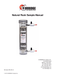
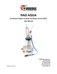
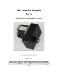
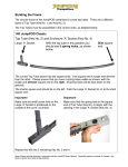
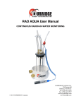
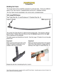
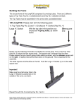
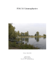
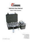
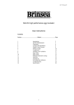
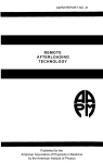
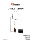
Natural Rock Sample Manual
Revision 2015-09-18
DURRIDGE Company Inc.
524 Boston Road
Billerica, MA 01821
Tel: (978) 667-9556
Fax: (978) 667-9557
[email protected]
www.durridge.com Table of Contents
Introduction
3
Fig. 1 Natural Rock Sample Components
1 RAD7 Radon Sensitivity Check
Fig. 2 Radon Sensitivity Check Setup
3
4
4
1.1 Purge the RAD7
4
1.2 Hook up to the Natural Rock Sample
4
1.3 Start a 3-Hour Test
5
1.3.1 Drying and Resealing the Rock Sample
Fig. 3 Natural Rock Sample drying loop configuration.
1.4 Radon Data Assessment
Fig. 4 Graph of Natural Rock Sample sensitivity test data
1.5 Multiple RAD7s
5
5
6
7
8
Fig. 5 Multiple RAD7 Sensitivity Check Configuration
1.6 Cumulative Spectrum
8
9
2 RAD7 Thoron Sensitivity Check
10
2.1 Thoron Measurement
10
Fig. 6 Thoron Measurement Standard Setup
2.1.1 Radon Interference
10
11
2.2 Rough Thoron Check
11
2.3 Better Thoron Check
11
Fig. 7 Thoron Sensitivity Check configuration
2.2.1 Experimental Protocol
2.2.2 Calculation
2.2.3 Assessing The Thoron Data
2
© 2015 DURRIDGE Company Inc.
12
13
13
13
Introduction
Introduction
The Natural Rock Sample is exactly that, a 21oz
(600g) sample of granite gravel from a stone
quarry, normally sold by the truckload as
construction material. It is enclosed in a
container that may be completely sealed using a
pair of ball valves and end caps.
Granite generally contains trace amounts of both
uranium and thorium that has been in the rock
since it was formed, millions if not billions of
years ago. Therefore all the progeny of both the
uranium and thorium decay chains are fully
supported and in full equilibrium down to 226Ra and 224-Ra.
When the rock sample is kept dry, it constitutes a
rock-steady emitter of both radon and thoron.
This manual shows how to take advantage of that
property to check the performance of a RAD7.
Please note that to keep the emission constant it
is essential that the rock sample be kept fully dry.
Always use a drying tube, with blue, active
desiccant in it, in the closed-loop radon
calibration circuit, or upstream of the desiccant
in the open-loop thoron calibration
configuration, in order to keep the rock sample
permanently bone dry. If the desiccant in the
drying tube gets used up it should be replaced or
regenerated. For thoron sensitivity
measurement, the carrier air, pushing the thoron
into the sample path, should be dried before it
enters the rock sample. These configurations are
illustrated on the following pages.
The Natural Rock Sample device can provide a
means for monitoring long-term changes in both
radon and thoron sensitivity. After calibration at
DURRIDGE Company, and with the optional
Thoron Calibration Check Kit, the Natural Rock
Sample can be used for low-precision checking
of both the radon and thoron sensitivities of any
RAD7.
Fig. 1 Natural Rock Sample Components
3
© 2015 DURRIDGE Company Inc.
1 RAD7 Radon Sensitivity Check
1 RAD7 Radon Sensitivity Check
After sitting sealed on a shelf for one month, the
radon in the Natural Rock Sample container will
have reached within 1% of a steady value, in
which the rate of emission of radon into the
container is equal to the rate of loss by decay and
leakage. If that quantity of radon is known, and
if it is distributed around an air loop of known
volume, then the radon concentration in the air is
known. If one of the devices in the air loop is a
RAD7, the RAD7’s reported radon concentration
may be compared with the known concentration,
and thus the sensitivity of the RAD7 may be
effectively checked. A correction may be
applied to the rock sample radon reading to
account for the ambient air radon concentration
(see section 1.4).
In practice, provided the device and tubing
configuration is identical to the calibration setup,
all that is required to check the RAD7 sensitivity
is to compare the ‘standardized’ average RAD7
reading (see below) with the standardized
average reading on the rock sample calibration
certificate. The ratio of the two will give a
correction factor that may be applied directly to
RAD7 readings.
1.1 Purge the RAD7
First, purge the RAD7 with dry air in an open
loop for at least 5 minutes, then switch to 1-day
protocol: select Setup, Protocol, 1-day and
push [ENTER]. Start a reading, still sampling
fresh air through a drying unit. Go to the third
status window (push the [Menu] key, then
push[ENTER], [ENTER], Rt Arrow, Rt Arrow,
and observe the relative humidity in the top right
corner. Keep the reading going until the RH is
below 9%, then switch off the RAD7.
If a correction is to be made to the rock sample
radon reading for radon added to the air loop by
the ambient air, after purging the RAD7, (see
section 1.4), the fresh-air measurement should be
kept going until at least one and preferably two
or three cycles are completed.
1.2 Hook up to the Natural Rock
Sample
Fig. 2 Radon Sensitivity Check Setup
4
Hook the RAD7 up to the Natural Rock Sample
using the tubing and small drying tube provided
with the rock sample. Use the configuration
shown in Figure 2, with the small drying tube
upstream of the Natural Rock Sample, and the
Rock Sample connection furtherest from the
screw cap connected to the RAD7 inlet filter. If
© 2015 DURRIDGE Company Inc.
1 RAD7 Radon Sensitivity Check
one end of the small drying tube has started to
turn pink, indicating that it is wet, that end
should be positioned closest to the RAD7 outlet.
hours). Average the last four readings. Record
that average with the date. If a thoron test is to
be conducted (see Section 2), the best time to do
it would be immediately after the radon check.
1.3 Start a 3-Hour Test
1.3.1 Drying and Resealing the Rock
Sample
Switch on the RAD7 and press the menu key.
Select 1-day protocol (Setup, Protocol, 1-day,
[ENTER]). Change the Recycle number to 6
(Setup, Protocol, Recycle, 06, [ENTER]). Put
the RAD7’s infrared printer in place and switch
off the RAD7.
Switch on the RAD7 printer. Switch on the
RAD7 and let it print out the header, including a
review of the settings. Check the printed review
to make sure the Cycle time is 00:30 (30
minutes) and the Recycle number is 06. Open
the ball valves on the rock sample container and
start a test (Test, Start, [ENTER]).
Keep the measurement going until all six cycles
are complete and the summary is printed out (3
After testing is complete, the Natural Rock
Sample should be thoroughly dried and prepared
for storage. To do this, set up the Natural Rock
Sample in a closed loop with a RAD7 and a
laboratory drying unit containing fresh desiccant.
(At this point the small drying tube that was used
in the 3-hour test should be sealed with yellow
caps and set aside until the next 3-hour test is
conducted.) The Natural Rock Sample should be
positioned downstream of the laboratory drying
unit, and the laboratory drying unit should be
connected with the end furthest from the screw
cap connected to the rock sample. The screw
cap end, which may be pink (indicating that it is
wet), should be connected to the RAD7 outlet as
shown in Figure 3, below.
Fig. 3 Natural Rock Sample drying loop configuration.
5
© 2015 DURRIDGE Company Inc.
1 RAD7 Radon Sensitivity Check
Set the RAD7 pump to ‘ON’ (Setup, Pump, On
[ENTER]), go to third status window (Setup,
Enter, Enter, Rt. Arrow, Rt. Arrow.) and
monitor the RH reading. Keep the air
circulating through the loop until the relative
humidity (RH) drops to 4% or below. The
drying process may take many hours.
Once the RH stays at 4% or below, turn off the
pump (Setup, Pump, Off [ENTER]), close the
ball valves, disconnect the tubing, and insert the
end caps on the Natural Rock Sample tube.
Mark the date on the label and store the Natural
Rock Sample with its tubing and small drying
tube on a shelf for a minimum of one month
before repeating the process.
If the ball valves are opened for any reason on a
later date, remove the old label and replace it
with a new label showing the last date on which
the valves were closed, and left closed. The
rock sample will be ready for another radon
check not before one month from that date.
1.4 Radon Data Assessment
If the rock sample was never calibrated, keep the
average of the last four readings (3, 4, 5, and 6)
in a record for future reference. (Figure 4 on the
next page shows a typical data set with the last
four readings selected.) Every standard RAD7
should produce nearly the same result with that
rock sample if its sensitivity is as calibrated and
if the rock sample is dry and has been sealed for
at least a month. For greater reproducibility, 2/3
of the ambient air radon concentration can be
subtracted from the averaged readings to correct
for the residual radon in the air in the system
after purging. However, if the ambient radon
concentration in the air is less than 100 Bq/m3
(2.7 pCi/L) the error introduced by ignoring it
will be less than 1%.
6
If the rock sample has been calibrated by
DURRIDGE Company, the calibration
certificate gives the standardized average of
readings 3, 4, 5 and 6, obtained with the standard
setup, a well purged and dry RAD7 and 30minute cycles. Thus the ratio of the value stated
on the rock sample calibration certificate to the
measured standardized average gives you the
correction factor directly. RAD7 readings
multiplied by that ratio will give readings
consistent with the DURRIDGE calibration
system to within, say, 8%. Thus the rock
sample, therefore, enables a calibration check
once a month, referred back to the EPA National
Standard and NIST, to within 8%.
You may also, if you wish, calculate the total
radon amount in the air loop, and hence
originally in the rock sample container. If the
radon amount is Rn and the volume of the air
loop is V, then the radon concentration is Rn/V.
The air volume in the rock sample is 459ml, a
standard RAD7 is 937ml and the tubing with
small drying tube is 16ml, for a total volume of a
standard rock sample system with standard
RAD7 of 1.412 L. If Rn is expressed in pCi,
then the radon concentration will be Rn/1.412
pCi/L. If Rn is expressed in Bq, then the radon
concentration will be Rn/1.412 Bq/L, or 1000 *
Rn / 1.412 Bq/m3.
In pCi, Rn = 1.412 * radon concentration in pCi/
L.
In Bq, Rn = 0.001412 * radon concentration in
Bq/m3
If the certified and observed standardized
average values differ by more than, say, 8%, we
recommend that the RAD7 be returned to
DURRIDGE Company for service. If, after
several monthly sensitivity checks, there is a
consistent ratio between the observed and the
certified standardized average radon
concentration, you may consider applying a
© 2015 DURRIDGE Company Inc.
1 RAD7 Radon Sensitivity Check
multiplier to all readings made with that RAD7,
to bring them in line with the rock sample
standard. If you notice a big jump, up or down,
in the reading, from the previous month, first
look to see if the RAD7 was properly purged
before the measurement was started. If there is
no obvious reason for the jump, the RAD7
should be returned to DURRIDGE for service.
Fig. 4 Graph of Natural Rock Sample sensitivity test data
7
© 2015 DURRIDGE Company Inc.
1 RAD7 Radon Sensitivity Check
1.5 Multiple RAD7s
Before using the Natural Rock Sample to check
a RAD7’s radon sensitivity, the rock sample
must be left sealed for a month, in order for the
radon inside the container to reach equilibrium.
That means a RAD7 can have its sensitivity
checked each month on a regular basis.
However, there is nothing to stop us hooking up
multiple RAD7s in series in the loop connected
to the rock sample. This increases the volume of
the loop and hence decreases the radon
concentration in the loop, but by a predictable
and reproducible amount. This method is
recommended for checking up to six RAD7s on
a monthly basis.
For the sake of argument, using rounded figures,
let us assume that the total quantity of radon
inside the rock sample container, when in
equilibrium, is equal to 2 Bq. Let us also
assume that the rock sample and tubing has an
air volume of 500ml while a RAD7 is 1L. Then
when the RAD7 is connected up to the rock
sample and the radon distributed around the
loop, the radon concentration will be 2 / 1.5 =
1.333 Bq/L = 1333 Bq/m3. If every additional
RAD7 adds 1L to the loop, then four RAD7s
would total 4.5L, including the rock sample and
tubing. The radon concentration in the loop
would then become 2 / 4.5 = 0.444 Bq/L = 444
Bq/m3. While this is less than 1333 Bq/m3 it is
still enough to make a good reading in two hours
and a high precision reading in 12 hours.
Fig. 5 Multiple RAD7 Sensitivity Check Configuration
Each month, all four RAD7s can be connected in
series with one another and thoroughly purged
and dried out, before being connected to the rock
sample to obtain a sensitivity check. Each
month the setup should be identical, with the
8
same number of RAD7s and the same pieces of
tubing to connect up the entire loop. During the
measurement all the RAD7 pumps, except one,
should be set to OFF ( Setup → Pump → Off,
[ENTER].)
© 2015 DURRIDGE Company Inc.
1 RAD7 Radon Sensitivity Check
If any of the RAD7s had developed a leak, the
radon concentration in the loop would fall
rapidly. Thus in addition to keeping a record of
the average readings during the check, for each
month, a record of the slope of the average for all
RAD7s should also be maintained, as the radon
concentration falls off over time from decay and
any leakage. If during one month the slope is
steeper than usual, that would be an indication of
a leak in the loop somewhere.
Although it is possible to combine several
RAD7s in a loop for monthly radon sensitivity
checks, this technique will not work for checking
thoron sensitivity, due to the loss of thoron in the
air as it travels around the loop. However, there
is no need to wait between successive thoron
checks and all the RAD7s can undergo the rough
thoron check individually, sequentially, without
any delay between measuring the thoron
response of one RAD7 and the next. The
monthly protocol may therefore be:
1. Connect all RAD7s in series, set all protocols
to 1-day, set all pumps, except one, to OFF.
Put a laboratory drying unit upstream of the
line, with one end open to fresh air.
2. Set the RAD7 with an active pump to Purge,
for 15 minutes, to purge all residual radon out
of the RAD7s and start to dry them out.
3. Select Test, Start, [ENTER] on all
RAD7s, starting a 1-day test in each of them
(with only one pump operating).
4. After at least two cycles (1 hour), or
preferably 3 cycles (1.5 hours), stop the tests.
5. Disconnect the large drying unit. Connect the
string of RAD7s to the rock sample and small
drying tube.
6. Open the valves and select Test, Start,
[ENTER] on all RAD7s (all still in 1-day
9
protocol and with all pumps, except one, set to
OFF).
7. Depending on the precision required, after
between 3 and 24 hours, the tests may be
stopped and the RAD7s disconnected.
8. If required, rough thoron checks may then be
performed with each RAD7, separately
connected to the rock sample.
9. Careful notes should be kept of all actions and
readings, and all data downloaded from each
RAD7 to a computer using CAPTURE
software.
10.The Natural Rock Sample should be
thoroughly dried and stored for at least one
month, using the procedure described in
Section 1.3.1.
1.6 Cumulative Spectrum
It is important that the cumulative spectrum
(based on counts from multiple cycles) be
printed and inspected periodically. It gives
excellent diagnostic information on the health of
the instrument. Using the Natural Rock Sample
to check the calibration of the RAD7 every
month is a convenient opportunity to inspect the
cumulative spectrum. With the Recycle set to 6
cycles, as indicated above, at the end of the sixth
cycle the RAD7 will automatically finish the run
and print out a run summary. This consists of
some data, a bar chart of the six readings and
then the cumulative spectrum. That spectrum
should show a sharp peak in the A window, about
midway between the boundaries. There may
also be peaks in the other three windows and at
5.3 MeV (210-Po) just to the left of the A
window. Please see the RAD7 manual for a
description and image of some possible
pathological spectra.
© 2015 DURRIDGE Company Inc.
1 RAD7 Radon Sensitivity Check
2 RAD7 Thoron Sensitivity Check
2.1 Thoron Measurement
The RAD7 is capable of making a direct
measurement of thoron gas concentration in air.
It does this by counting 216Po decays inside its
measurement chamber. Thoron however has a
short half life, 55.6s, so most of the thoron in the
sample will be lost during acquisition if the time
from sampling to entering the measurement
chamber exceeds even a minute. Therefore
when measuring thoron the sample acquisition
time must be as short as conveniently possible,
and always consistent. Additionally, the exact
same setup should be used for thoron calibration
as for thoron measurement. This setup
necessarily involves a specific length of tubing
and a small tube of desiccant, as the RAD7
detector is less sensitive in a humid environment.
The setup assumed in the RAD7 data processing
and stated as standard in the manual consists of a
small drying tube, which may be used as a wand
for sniffing, along with a standard input tubing of
36” (91.4cm) length and inner diameter of
3/16” (4.8mm), as shown below.
This typically gives the RAD7 a thoron
sensitivity of about half its radon Sniff
sensitivity. The 216Po daughter of thoron has only
a 145mS half life so the main component in the
response time of the RAD7 to a step change in
thoron concentration is the time taken to acquire
the sample. The response is virtually
instantaneous.
Fig. 6 Thoron Measurement Standard Setup
10
© 2015 DURRIDGE Company Inc.
1 RAD7 Radon Sensitivity Check
heavily dependent on the pump flow rate and
even the position of items in the setup. If the
desiccant is placed upstream instead of
downstream of the rock sample it will make no
difference to the average radon reading, but will
make a big difference to the thoron readings.
Even just switching the connections to the rock
sample can affect the thoron readings. However,
if the setup remains identical in every respect
from one monthly check to the next, if the RAD7
pump is still working at close to the same flow
rate, and if the inlet filter is not blocked, then
thoron readings made with this setup will be
similar from one month to the next. After
several months of experience the user will know
the typical variation and will recognize an
anomalous shift, should it occur.
2.1.1 Radon Interference
The alpha particle from 216Po decay has an
energy of 6.78 MeV, which is between the 218Po
and 214Po peaks in the 222Rn decay chain. That
places it within the B window of the RAD7
spectrum, while the 214Po peak lies in the C
window. About 1% of the 214Po counts are in a
low energy tail from the peak, and spill into
window B. The spill factor is measured during
calibration and the count in window B is
corrected for that spill by the RAD7 and by
CAPTURE software when calculating the thoron
concentration. Nevertheless, the presence of a
large spill from window C would increase the
uncertainty of the thoron count in window B. It
is therefore important that the C window count
be low when performing a thoron measurement
or calibration.
If a radon calibration check of a RAD7 has been
performed with a Rock Sample, it would be good
to wait an hour or two for the count rate in
window C to drop below 10 cpm, before
proceeding with the thoron calibration check.
2.2 Rough Thoron Check
Before closing the ball valves and disassembling
the setup, change the protocol to Thoron by
selecting Setup, Protocol, Thoron,
[ENTER]. Then turn the RAD7 off and back on,
and let the printer print out the new header for
thoron.
Start a measurement. Let it run for at least 15
minutes (3 five-minute cycles), or more if you
would like a higher precision average. Average
all the thoron readings. Store the thoron average
reading with the radon average.
This thoron reading cannot be used to check the
thoron sensitivity of the RAD7, as the reading is
11
2.3 Better Thoron Check
A more accurate thoron sensitivity check
involves the Thoron Calibration Check Kit,
which is sold separately. To check the thoron
sensitivity of a RAD7 using this kit, the
measurement must be made in precisely the same
conditions and using the same configuration as
thoron measurements in regular use. In standard
thoron protocol, the RAD7 has 1m of 3/16” ID
tubing between the inlet filter and a small drying
tube, which may be used as a wand for sniffing
purposes.
The thoron check process therefore requires that
the sampling point at the end of the small drying
tube must be open to the air. It is the thoron
concentration at that sampling point that we
measure. Thus we put a T-connector at that
location, inject thoron at a known rate, using a
carrier with less than the RAD7 flow rate, and
with fresh air from the other side of the Tconnector supplying the balance of air to make
up the RAD7 flow rate. This configuration is
illustrated on the following page.
© 2015 DURRIDGE Company Inc.
1 RAD7 Radon Sensitivity Check
Fig. 7 Thoron Sensitivity Check configuration
12
© 2015 DURRIDGE Company Inc.
1 RAD7 Radon Sensitivity Check
2.2.1 Experimental Protocol
a) Set up the experiment exactly as in the
diagram above, or else with the RAD7
sampling path in exactly the same setup as
will be used for measuring thoron.
b) Adjust the flow rate through the rock sample
to 0.55 L/min. A flow rate of 0.55 L/min is
chosen as a standard flow rate for injecting
thoron into the RAD7 sample path because
that may be relied upon to be less than the
RAD7 pump flow rate, that may range from
0.6 L/min to 1 L/min or higher. With the set
up as shown in the diagram above, run the
external pump and adjust the needle valve so
that the air flowing through the rock sample is
0.55 L/min.
c) Move the flow meter to the RAD7 outlet.
Remove the flow meter from its position
between the needle valve and the rock sample
and reconnect the tubing so that the needle
valve is connected directly to the rock sample.
Connect RAD7 outlet to the input of the flow
meter. The external pump can be kept running
during this maneuver.
d) Change the RAD7 to thoron protocol. Use the
default thoron protocol (Setup, Protocol,
Thoron, [ENTER]), or choose the default and
then change individual parameters (e.g. cycle
time) as desired. Turn off the RAD7, turn on
the printer, turn on the RAD7 and let it print
out a header. Examine the header to make
sure everything is OK.
e) Start a reading: Test, Start, [ENTER].
2.2.2 Calculation
With an identical rock sample air flow rate (0.55
L/min) and identical tubing attached to the T
connector, for every thoron calibration check, the
rate of injection of thoron into the sample flow
13
will always be the same. Let this be Th. The
units of Th are pCi per minute or Bq per minute.
If the RAD7 flow rate, measured at the RAD7
outlet, is V L/min, then the thoron concentration
in the sample air flow at the sampling point
(which is very close to the T connection) will be
Th/V. If Th is expressed in pCi/min and V is in
L/min then Th/V will be pCi/L. If Th is
expressed in Bq/min and the flow is in L/min
then Th/V will be Bq/L. To convert to Bq/m3
multiply by 1000.
2.2.3 Assessing The Thoron Data
For an uncalibrated rock sample, note the
average thoron reading and the RAD7 flow rate.
Multiply the thoron reading by the flow rate to
get Th, the rate of injection of thoron into the
sample flow (for units of Bq/m3 and L/min,
divide the product by 1,000 to get Bq/min). The
experiment may be repeated as often as desired.
There is no need to wait for any ingrowth.
However, after conducting this experiment, the
rock sample must be left sealed for a month
before a radon check may be performed. The
obvious time to do this experiment is
immediately after a radon check.
As an option, DURRIDGE Company will
calibrate a rock sample for thoron. With a setup
as above and a flow rate of 0.55 L/min through
the rock sample, we give you the rate of injection
of thoron into the RAD7 sample path. You may
then divide that by the flow rate of the target
RAD7 to obtain the thoron concentration at the
sampling point. This may be compared with the
thoron reading in the RAD7 and a correction
factor derived.
Records of the radon and thoron readings should
be kept safely for later reference and
comparison.
© 2015 DURRIDGE Company Inc.