1
MobilePro-Anschalte-Installations-Handbuch_4_2_13_EN
3
ChristianHartleb
MobilePro-Anschalte-Installations-Handbuch_4_2_13_EN
Inhaltsverzeichnis
1 Copyright.....................................................................................................................................................1/63
1.1 Explanation of symbols................................................................................................................1/63
2 Safety instructions.......................................................................................................................................2/63
2.1 Safety standards and certifications...............................................................................................2/63
3 Introduction.................................................................................................................................................3/63
3.1 Target group..................................................................................................................................3/63
4 Installation...................................................................................................................................................4/63
4.1 Scope of delivery..........................................................................................................................4/63
4.2 Prerequisites..................................................................................................................................4/63
4.3 Operating elements/connections...................................................................................................5/63
4.3.1 Connections, switches (buttons) on the Mobile Pro............................................................5/63
4.3.2 Connections on the switch box............................................................................................8/63
4.4 Mounting in the equipment locker..............................................................................................10/63
4.5 Installing the Mobile Pro............................................................................................................10/63
4.5.1 Connection assignment of the interfaces...........................................................................10/63
4.6 Additional information about Mobile Pro M-Versions..............................................................24/63
4.6.1 Mobile Pro M1..................................................................................................................24/63
4.6.2 Mobile Pro M2..................................................................................................................24/63
4.7 Description of the installation procedure (to be clarified in advance)........................................25/63
4.7.1 Teleserver Mobile Pro system...........................................................................................25/63
4.7.2 FMC Mobility Client.........................................................................................................26/63
5 Commissioning..........................................................................................................................................27/63
5.1 Switching on/off.........................................................................................................................27/63
5.1.1 Switching the switch box on/off........................................................................................27/63
5.1.2 Switching Mobile Pro Mobile Pro on/off..........................................................................27/63
5.2 Service Access............................................................................................................................27/63
5.2.1 Service access using the desktop/laptop computer...........................................................27/63
5.2.2 Service access directly at the system.................................................................................27/63
5.2.3 Service access via ISDN (remote)RAS.............................................................................28/63
5.2.4 Service >> Filemanager....................................................................................................28/63
5.3 Access for User and Administrator.............................................................................................29/63
6 System settings..........................................................................................................................................31/63
6.1 Numbering plan..........................................................................................................................31/63
6.1.1 WEB programming:..........................................................................................................31/63
6.1.2 Example.............................................................................................................................32/63
7 Traces & Logfiles, DST- Dienste der Durchschleiftechnik...................................................................33/63
7.1 Traces..........................................................................................................................................33/63
7.1.1 Voice 4 Server trace..........................................................................................................33/63
7.1.2 ISDN Traces......................................................................................................................36/63
7.2 Occupied time table....................................................................................................................36/63
7.3 Log files......................................................................................................................................36/63
7.4 Event Viewer..............................................................................................................................37/63
7.5 ISDN setup..................................................................................................................................39/63
7.5.1 Reducing the number of controllers..................................................................................40/63
7.5.2 Assigning the B-channels..................................................................................................43/63
7.5.3 Media.................................................................................................................................45/63
i
MobilePro-Anschalte-Installations-Handbuch_4_2_13_EN
Inhaltsverzeichnis
8 Public Services...........................................................................................................................................46/63
9 IT security..................................................................................................................................................47/63
9.1 Release further Ports...................................................................................................................47/63
10 Numbering plan - detail.........................................................................................................................48/63
10.1 Simplified diagram...................................................................................................................48/63
10.1.1 Numbering plan for incomming calls..............................................................................48/63
10.1.2 Numbering plan for dialling and grafical user input (GUI)............................................48/63
10.1.3 Numbering plan for outgoing call...................................................................................49/63
10.1.4 Simplified diagram of the transform-rules......................................................................49/63
10.1.5 Plans................................................................................................................................50/63
10.1.6 Mixed Extension lengths and "Function numbers with DTMF redialling"....................56/63
11 Troubleshooting......................................................................................................................................58/63
12 FAQs........................................................................................................................................................59/63
13 Uninstalling the Mobile Pro...................................................................................................................60/63
14 Final decommissioning...........................................................................................................................61/63
15 Technical data.........................................................................................................................................62/63
16 GLOSSARY............................................................................................................................................63/63
ii
1 Copyright
Copying or reproducing these instructions — in whole or in part — is permitted only with the written
approval of:
Speech Design GmbH
Industriestraße 1
82110 Germering
Subject to change and correction.
1.1 Explanation of symbols
The following symbols are used in this manual:
> This symbol introduces an instruction.
• This symbol identifies list items.
♦ This symbol identifies lower-level list items.
◊ This symbol identifies the next lowest level of list items.
This symbol identifies tips or additional instructions.
This symbol draws your attention to important information or prerequisites.
This symbol and text identify warnings that must be observed, as otherwise property damage or data loss
may result.
This symbol and text identify warnings that must be observed, as otherwise a risk of injury or
death exists.
1/63
2 Safety instructions
The system has been manufactured and inspected with great care. Despite this, we do not recommend using it
in situations where malfunctions can cause damage or consequential damage. The manufacturer shall not be
liable beyond the extent provided by law.
Do not expose the Mobile Pro to heat (direct sunlight, radiators).
Avoid contract with water and chemicals as well as strong vibrations. Otherwise, the Mobile Pro may be
destroyed.
Only authorized persons may open the housing.
The power plug must always be disconnected before opening. Refer also to the section Swich on,
switch off.
Failure to observe these rules results in a risk of fatal injury from electric shock!
The power socket must be installed close to the device and easily accessible.
The S2M (PRI)/E1 connections must be operated on an NT primary rate connection or on a PBX.
The S0 (BRI) connections are to be operated on an NTBA or on a PBX.
Any other use or unauthorized modifications to the device will void the authorization to operate it.
The keyboard, mouse and monitor may be plugged in or unplugged only if the Mobile Pro is switched off
and the power plug is disconnected. Otherwise, malfunctions of or damage to the Mobile Pro or connected
devices may result.
For security reasons, we recommend operating Mobile Pro in a subnet when it is connected to a LAN. No
firewall is installed on Mobile Pro.
Only software which is explicitly released from manufacturer is supported. No liability for damages
—regardless of their legal basis— shall be accepted if 3rd party software is used.
2.1 Safety standards and certifications
Mobile Pro fulfills the safety regulations of EN60950.
Caution! Mobile Pro fulfills the requirements for class B radio radiation only if no audio lines are
connected.
2/63
3 Introduction
This manual describes the installation, commissioning and configuration of the Mobile Pro system. It also
describes the creation of trace and log files for fault analysis and the possible service access points for
commissioning the system.
3.1 Target group
This manual is intended for service technicians who connect the Mobile Pro and put it into service.
For information about administration of Mobile Pro, refer to the Administration manual.
3/63
4 Installation
4.1 Scope of delivery
Check to make sure that the delivery is complete. If you find damage to the device or accessories, do
not switch on the device under any circumstances, but contact your supplier.
• 1 Mobile Pro
• 1 power cable for the power supply (rubber connector)
• Switch boxes, depending on the model:
♦ Mobile Pro 30/80: 1 switch box (1 x PRI) with power supply adapter
♦ Mobile Pro 30/500: 1 switch box (1 x PRI) with power supply adapter
♦ Mobile Pro 60/160: 1 switch box (2 x PRI) with power supply adapter
♦ Mobile Pro 60/500: 1 switch box (2 x PRI) with power supply adapter
♦ Mobile Pro 4/4: 2 switch boxes (2 x BRI per switch-box) with power supply adapter
♦ Mobile Pro 8/8: 4 switch boxes (2 x BRI per switch-box) with power supply adapter
• 1 "Teleserver Mobile Pro Documentation" CD consisting of:
♦ 1 Administration manual
♦ 1 user manual
♦ 1 short reference guide with user examples
♦ 1 dial-up scheme
♦ 1 menu structure
♦ 1 licensing agreement
♦ 1 End User License Agreement (EULA)
♦ 1 CE Declaration of Conformity
• Cables, depending on the model:
For 1x PRI variants
Mobile Pro 30/80:
4 connector cables for PRI connections
Mobile Pro 30/500: 4 connector cables for PRI connections
2 cables with open ends
2 cables with open ends
For 2x PRI variants
Mobile Pro 60/160: 8 connector cables for PRI connections
Mobile Pro 60/500: 8 connector cables for PRI connections
4 cables with open ends
4 cables with open ends
For BRI variants
Mobile Pro 4/4:
Mobile Pro 8/8:
8 connector cables for BRI connections
16 connector cables for BRI connections
• 1 crossover cable (LAN)
• 4 rubber feet (for tabletop installation of unit)
4.2 Prerequisites
1. Power supply system: 220V network
2. Connection(s) to the PBX or NT connection for Mobile Pro:
♦ 1 NT PRI/BRI connection
♦ 1 PBX PRI/BRI connection
♦ Network access (LAN)
For additional information, refer to the chapter entitled TechnicalData.
4/63
MobilePro-Anschalte-Installations-Handbuch_4_2_13_EN
10/19/09 16:23:19
Check the configuration for the assignment of the B-channels (incoming/outgoing/bidirectional) in the
trunk (see Section [Assigning the B-channels].
Check whether your PBX allows Explicit Call Transfer and configure this if necessary.
4.3 Operating elements/connections
Only the following interfaces may be used for the connections: PS/2 mouse, PS/2 keyboard, VGA monitor,
LAN, ISDN (PRI/BRI).
The PRI/BRI cables must not be kinked under any circumstances.
Do not plug in the power plug until all connector cables are connected to the Mobile Pro.
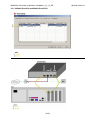
4.3.1 Connections, switches (buttons) on the Mobile Pro
Front side
Rear side
5/63
MobilePro-Anschalte-Installations-Handbuch_4_2_13_EN
10/19/09 16:23:19
The system is factory-configured to start automatically when the power supply voltage is switched on
(see rear of the device).
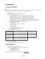
View of the RJ45 jacks for Mobile Pro S2M (PRI) variants:
Mobile Pro 30/80 and Mobile Pro 30/500
Mobile Pro 60/160 and Mobile Pro 60/500
View of the RJ45 jacks for Mobile Pro S0 (BRI) variants:
Mobile Pro 4/4
Mobile Pro 8/8
6/63
MobilePro-Anschalte-Installations-Handbuch_4_2_13_EN
7/63
10/19/09 16:23:19
MobilePro-Anschalte-Installations-Handbuch_4_2_13_EN
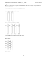
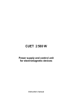
4.3.2 Connections on the switch box
Front view of the switch box for Mobile Pro 30/80 and Mobile Pro 30/500 variants:
Front view of the switch box for Mobile Pro 60/160 and Mobile Pro 60/500 variants::
Front view of the switch box for Mobile Pro 4/4 and Mobile Pro 8/8 variants::
• Description of the LEDs (front view):
♦ PWR (green) power supply
♦ STAT (green) status display, call through enabled
♦ CTRL (orange) enable signal from call through service
8/63
10/19/09 16:23:19
MobilePro-Anschalte-Installations-Handbuch_4_2_13_EN
10/19/09 16:23:19
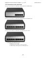
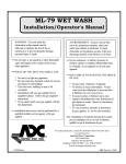
Rear side:
Lock switch
The lock switch is used to enable and disable the call through system.
• Lock switch switched on (pressed)-> call through disabled (e.g. for maintenance work on Mobile Pro
system).
• Lock switch switched off (not pressed)-> call through enabled (functions of Mobile Pro).
Lock switch function of the switch box
When the switch box is de-energized or when the lock switch is pressed, the switch box connects the NT
(trunk connection) directly to the PBX. If the lock switch is not pressed, the lines are routed to the Mobile Pro
via the switch box and the control is transferred to the software (application) (normal operation). This
mechanism is safeguarded by an additional watchdog function so that in the event of an error, all telephone
calls can again be routed directly via the switch box if necessary. Depending on the error situation, this
emergency mechanism can be triggered by the hardware or the software (e.g. power-off).
Each time the lock switch is pressed, there is a brief interruption of the trunk line.
9/63
MobilePro-Anschalte-Installations-Handbuch_4_2_13_EN
10/19/09 16:23:19
4.4 Mounting in the equipment locker
The locker depth and screw connections of the 19" equipment locker may vary from manufacturer to
manufacturer.
• Where applicable, contact the manufacturer of your equipment locker about the possibilities for
installing rack-mounted units.
• If necessary, obtain suitable guide rails from the manufacturer of your equipment locker before
installation begins.
The cables plugged into the rear of the Mobile Pro must not be kinked under any circumstances.
Therefore, note the locker depth when rack-mounting the unit.
• The switch box should be installed close to the NT connection.
4.5 Installing the Mobile Pro
The system is looped in between the NT termination and the PBX.
4.5.1 Connection assignment of the interfaces
Connection diagram
Each example shows the first two controler connections. All other cables have to be connected
consecutively as shown in the examples.
• If not all ports are taken in the Mobile Pro-System, it is necessary to deactivate them in the ISDN
Setup (e.g.: install Mobile Pro 60/500 but only use 1 x PRI or e.g.: install Mobile Pro 8/8 but only use
6 x BRI).
•
10/63
MobilePro-Anschalte-Installations-Handbuch_4_2_13_EN
10/19/09 16:23:19
• It is not allowed to set any breaks in between the ports in the ISDN Setup nor in the controller. The
sorting always beginns with the TE ports and ends with the NT ports.
• Following examples show the standard installation of Mobile Pro including the standard configuration
in the ISDN Setup.
In order to make the following examples more clearly we used coloured cables for the pictures.
Delivered are grey patch cables.
11/63
MobilePro-Anschalte-Installations-Handbuch_4_2_13_EN
4.5.1.1 Mobile Pro 4/4
12/63
10/19/09 16:23:19
MobilePro-Anschalte-Installations-Handbuch_4_2_13_EN
10/19/09 16:23:19
This is an example! Take care that there are set no any breaks either in between the ports in the ISDN
Setup nor in the controller.!!
> Connect the PBX to port PBX
> Connect the trunk to port trunk
> Connect port TO SYSTEM with the first port (TE)
> Connect port from SYSTEM with first port port (NT)
The wires of the cable between switch box and Mobilen Pro must not be kinked under any circumstances.
13/63
MobilePro-Anschalte-Installations-Handbuch_4_2_13_EN
4.5.1.2 Mobile Pro 8/8
14/63
10/19/09 16:23:19
MobilePro-Anschalte-Installations-Handbuch_4_2_13_EN
10/19/09 16:23:19
This is an example! Take care that there are set no any breaks either in between the ports in the ISDN
Setup nor in the controller.!!
> Connect the PBX to port PBX
> Connect the trunk to port trunk
> Connect port TO SYSTEM with the first port (TE)
> Connect port from SYSTEM with first port port (NT)
The wires of the cable between switch box and Mobilen Pro must not be kinked under any circumstances.
15/63
MobilePro-Anschalte-Installations-Handbuch_4_2_13_EN
4.5.1.3 Mobile Pro 30/80 and Mobile Pro 30/500
16/63
10/19/09 16:23:19
MobilePro-Anschalte-Installations-Handbuch_4_2_13_EN
10/19/09 16:23:19
This is an example! Take care that there are set no any breaks either in between the ports in the ISDN
Setup nor in the controller.!!
> Connect the PBX to port PBX
> Connect the trunk to port trunk
> Connect port TO SYSTEM with the first port (TE)
> Connect port from SYSTEM with first port port (NT)
The wires of the cable between switch box and Mobilen Pro must not be kinked under any circumstances.
17/63
MobilePro-Anschalte-Installations-Handbuch_4_2_13_EN
10/19/09 16:23:19
4.5.1.4 Mobile Pro 60/160 und Mobile Pro 60/500
This is an example! Take care that there are set no any breaks either in between the ports in the ISDN
Setup nor in the controller.!!
18/63
MobilePro-Anschalte-Installations-Handbuch_4_2_13_EN
10/19/09 16:23:19
This is an example! Take care that there are set no any breaks either in between the ports in the ISDN
Setup nor in the controller.!!
> Connect the PBX to port PBX
> Connect the trunk to port trunk
> Connect port TO SYSTEM with the first port (TE)
> Connect port from SYSTEM with first port port (NT)
The wires of the cable between switch box and Mobilen Pro must not be kinked under any circumstances.
19/63
MobilePro-Anschalte-Installations-Handbuch_4_2_13_EN
10/19/09 16:23:19
4.5.1.5 Simplified diagram in call through mode for BRI (S0):
4.5.1.6 Simplified diagram in call through mode for PRI (S2M):
The following diagrams are showing the connection in customers infrastructure based on an example of PRI
(S2M) connection:
20/63
MobilePro-Anschalte-Installations-Handbuch_4_2_13_EN
If the cables are not routed correctly, the trunk may block the connection for 30 min.
• Top view of RJ45 plug to PBX:
PRI (S2M)-connection switch-box to NT (trunk interface)
21/63
10/19/09 16:23:19
MobilePro-Anschalte-Installations-Handbuch_4_2_13_EN
PRI (S2M)-connection switch-box to NT (trunk interface) and to PBX
PRI (S2M)-connection switch-box to NT (trunk interface), to PBX and to Mobile Pro
22/63
10/19/09 16:23:19
MobilePro-Anschalte-Installations-Handbuch_4_2_13_EN
10/19/09 16:23:19
Caution: Only use the delivered original cables!
Terminal connection to NT
Terminal connection, if RJ45 is not available or assignment does not correspond to the illustration connection
switch-box to NT:
> TX has to be connected to TX and RX to RX, towards NT-connection
Terminal connection to the PBX
Terminal connection, if RJ45 is not available or assignment does not correspond to the illustration connection
switch-box to NT:
> TX has to be connected to TX and RX to RX , towards PBX.
23/63
MobilePro-Anschalte-Installations-Handbuch_4_2_13_EN
10/19/09 16:23:19
4.6 Additional information about Mobile Pro M-Versions
4.6.1 Mobile Pro M1
The installation of a Mobile Pro M1 version is always a project based business, which must be prepared in
depth. For each customer a "numbering plan" has to be issued and programmed. Please see chapter
"Numbering plan" for more information. The Mobile Pro M1 version needs a PRI trunk line which is
configured exclusively for outgoing calls.
Notes
Compared to the "conventional" installation of Mobile Pro in all ISDN-lines between trunk interface and PBX
following differences have to be considered:
1. Installation
♦ Mobile Pro M1 has to be connected to a „separate“ PRI-line.
2. PBX
♦ The separate PRI-line is assigned to a cross connections (as a "sub-PBX". E. g., can be
reached with „9“)
♦ For every Mobile Pro M1 user parallel signalling to "sub-PBX" + user Ext. (e.g. 9-317)has to
be programmed.
♦ Establish a transit option between trunk and "sub-PBX".
3. Trunk /network
♦ The separate PRI-line must be configured only for "outgoing" calls.
4.6.2 Mobile Pro M2
24/63
MobilePro-Anschalte-Installations-Handbuch_4_2_13_EN
10/19/09 16:23:19
The installation of a Mobile Pro M1 version is always a project based business, which must be prepared in
depth. For each customer a "numbering plan" has to be issued and programmed. Please see chapter
"Numbering plan" for more information. The Mobile Pro M2 version needs an own bi-directional PRI trunk
(own trunk number/outside line number!).
Notes
Compared to Mobile Pro M1 resp. Mobile Pro there is just one difference to be considered:
1. Trunk / network
♦ The separate PRI-line must be bi-directional with its own trunk number (outside line number).
4.7 Description of the installation procedure (to be clarified in
advance)
4.7.1 Teleserver Mobile Pro system
1. Connect the switch boxes to the Mobile Pro system (see diagram).
2. Connect a laptop with the crossover cable provided or connect a mouse, keyboard and monitor
directly to the Mobile Pro box.
3. Plug the power supply of Mobile Pro and the switch box.
4. Switch on the Mobile Pro. After service login (via VCN or via WBM)administrate the system and the
basis configuration (RAS-settigns, numbering plans,...).
5. Check the configuration for the assignment of the B-channels (incoming/outgoing/bidirectional) in the
trunk and configure the settings of Mobile Pro accordingly.
6. Set up the IP configuration (IP address, etc.) for web administration in the customer network.
We recommend to configure a fixed IP address.
25/63
MobilePro-Anschalte-Installations-Handbuch_4_2_13_EN
10/19/09 16:23:19
1. Perform a restart of the Mobile Pro box.
2. Press the lock switch (at the rear of the switch box) to loop in Mobile Pro in the NT-PBX line.
3. Set up a subscriber (extension, mobile phone).
4. Mobile Pro test sequence:
a. Call the Mobile Pro extension from an external number -> extension and the registered
mobile phone must ring
◊ -check displayed number and take the call.
b. Dial an external target from the Mobile Pro extension -> target must ring.
c. Call from a registered mobile phone the according registered Mobile Pro extension -> entry
into main menu.
d. Call from a registered mobile phone any extension -> check displayed number = Must be
extension number of the user, not his mobile number.
e. Call from any internal extension a registered (Mobile Pro-) extension -> Mobile Pro
extension and activated call forwarding target (e.g. mobile phone) must ring (Caution: for
internal calls the registered extension must be re-routed to its own Mobile Pro account). f.
Test the functional phone numbers (callback, etc.).
5. Test the remote access, afterwards change the Windows administrator password.
6. Perform a backup of the settings.
7. Explain to customer's administrator the WEB access of the system and change the password.
8. If desired: Configure the settings for e-mail delivery.
9. For further administration please explain the backup and restore function to the customer.
4.7.2 FMC Mobility Client
For details on installing and using the FMC Mobility Client software, refer to the FMC Mobility Client
manual.
26/63
5 Commissioning
5.1 Switching on/off
5.1.1 Switching the switch box on/off
The switch box is switched on and off by plugging in/unplugging the power supply.
> Switch on the lock switch (pressed) to disable the call through system during commissioning.
5.1.2 Switching Mobile Pro Mobile Pro on/off
Switch the device on/off using the button on the front side only! To switch off, press and hold the button for
approx. 3 sec. Mobile Pro Mobile Pro shuts down automatically. Do not unplug the power plug until the green
operation LED has gone out (after approx. 30 seconds) so that the device can shut down properly.
5.2 Service Access
For commissioning, there are two 2 options for the service access:
• Using the desktop/laptop computer
• Directly on the system
5.2.1 Service access using the desktop/laptop computer
Network connection using crossover cable
For the service access with your desktop/laptop, you need VNC client software and a crossover cable (see
Scope of delivery]).
> Change the IP address of your desktop/laptop to 10.0.0.2 and the subnet mask to 255.0.0.0.
> Connect your desktop/laptop with the Mobile Pro and use the cable specified above!
> Start VNC and enter the IP address 10.0.0.10 (default factory setting).
> Enter the password "service" (case-sensitive) to gain access.
You now see the desktop of the Mobile Pro and can log in to the system as described in the following section.
5.2.2 Service access directly at the system
You can also obtain service access by connecting a keyboard, mouse and monitor directly to the Mobile Pro.
The keyboard, mouse or monitor may be plugged in or unplugged only if the Mobile Pro is switched off
and the power plug is disconnected. Otherwise, malfunctions of or damage to the Mobile Pro or connected
devices may result.
> Connect the monitor, mouse (PS/2) and keyboard (PS/2) to the rear side of the Mobile Pro.
> Connect the power plug to the power supply.
> Switch on the Mobile Pro and the monitor.
27/63
MobilePro-Anschalte-Installations-Handbuch_4_2_13_EN
10/19/09 16:23:19
The Mobile Pro boots up. The Windows login dialog appears.
>
Login as the administrator:
Username Administrator, Password mobilepro
You now see the desktop of the Mobile Pro.
5.2.3 Service access via ISDN (remote)RAS
• Login in WBM as administrator and select menu "Service Settings".
• Compelte the "RAS setting" fields.
To get remote access:
> Enter the RAS number to establish a data remote transmission
> Start the VNC-Viewer and enter 10.0.0.1 in "Server" field
> In field "Password": set service
5.2.3.1 Optimized functionality
Instead of an ISDN-connection it is also possible to establish a LAN-connection as RAS (remote access
service).
5.2.3.2 Add on information to RAS-dial in with Mobile Pro M1
An "external" RAS-access is not possible with Mobile Pro M1. The call direction has to be turned around. In
total there a three support-units which can be dialled (level-1, level-2 and level-3). Each level unit has to be
configured independtly (RAS Dial).
To start the remote-access call the administrator user number and enter the TUI service PIN. Afterwards enter
the key digits according to the row in the RAS Dial (e.g.: row 1 = key digit 1, ...), in which the desired
name/number is listed.
5.2.4 Service >> Filemanager
Using the Mobile Pro file manager, you can upload and download files using the web browser without having
access to the web administration of the system.
To access the file manager, first establish a connection from your desktop/laptop to the Mobile Pro (refer to
the section "Service access with the desktop/laptop").
So that you can access the corresponding files, first copy them into the following directory under this path:
C:\Program Files\FMCgatewaySuite\Files
(The link Service-Filemanager is on the desktop).
Double-click the link OctopusMobile-Filemanager (Internet Explorer link); a browser window
appears that shows the contents of the "Files" folder.
• Upload: Upload files with "Browse" and "Upload".
• Download: Select a file and and store it any folder.
28/63
MobilePro-Anschalte-Installations-Handbuch_4_2_13_EN
10/19/09 16:23:19
For service access via ISDN ((remote access service)), the download to your desktop/laptop takes place
automatically.
5.3 Access for User and Administrator
1. Log-in
• User
User password (default): 1234
Here, the user can enter his user number (extension number) and his code number to get access to the web
user interface. The user can then change his settings via web.
Further information for the user are available in user manual or online help.
• Administrator
Admin password (default): 1234
• Administrator - menu - overview
System administration
29/63
MobilePro-Anschalte-Installations-Handbuch_4_2_13_EN
10/19/09 16:23:19
Administrator
System parameters
Numberingplan
e-mail
User rights level
Functional phone numbers
User administration
User overview
New user
Music on Hold
Selection
Upload
Service
Service Settings
RAS Dial
System information
Logfiles
Backup
Restore
Reset
Filemanager
Logout
Further information for the administrator are available in administrator manual or online help.
• Public
Public is 'open' for everybody without any user number or password. See chapter "Public Services"
30/63
6 System settings
6.1 Numbering plan
The numbering plan enables you to fit the Called Num and Calling Num individually. For a regular
installation, the numbering plan must not be edited. For futher information see chapter Numbering plan in
detail at the end of this document.
6.1.1 WEB programming:
1. Create numbering plan
Log in as "Administrator" is requisited.
System administration
Administrator
System parameters
Numberingplan
e-mail
User rights level
Functional phone numbers
User administration
User overview
New user
Music on Hold
Selection
Upload
Service
Service Settings
RAS Dial
System information
Logfiles
Backup
Restore
Reset
Filemanager
31/63
MobilePro-Anschalte-Installations-Handbuch_4_2_13_EN
10/19/09 16:23:19
Logout
> Select a template
> Complete the empty fields accordingly
> Click >>Save and create numbering plan<<
All values which you have entered into the system before are transferred automatically into the selected
template. To save modifications or to create further new rules proceed as follows:
6.1.2 Example
Create numbering plan
User data
Template:
Please select
National Prefix:
0
International Prefix:
00
Country code:
49
Area code:
89
Phone number PBX :
89455
Number for an outside line:
0
Alternative dial in number
011
length of extension number (max): 3
Press the button "Save and create numerbing plan" all entered values are tranferred into the selected
tamplate.
In individual case
• Change numbering plan for incoming calls
• Change numbering plan for outgoing calls
• Change numbering plan for dialling and GUI input
32/63
7 Traces & Logfiles, DST- Dienste der
Durchschleiftechnik
7.1 Traces
7.1.1 Voice 4 Server trace
Voice 4 Server is very useful for troubleshooting in real time.
It displays phone numbers (Calling, Called Party Number) and the currently executed functions.
Example 1:
A user is set up in Mobile Pro as follows:
User administration >> Georg Mark >> User data
First name:
Georg
Last name:
Mark
Department:
Service
Password (PIN):
1234
User number:
101
Language:
German
Displayed number at called party:
08981802101
Mobile phone:
01708024737
• Action 1:
♦ Call into the main menu.
♦ Call from the mobile phone (0170-802 47 37) to the fixed-line number (089-81802-101)
• Column 1: Channel
• Column 2: Calling Number (number of the caller)
• Column 3: Called Party Number (dialed number)
• Column 4: Function (agent in the main menu)
Information: The green fields which are shown top in the picture, change their colours depending on the
status:
* Red = active (calling) status
* Green= passive (idle) status (the appropriate row shows the last actions)
33/63
MobilePro-Anschalte-Installations-Handbuch_4_2_13_EN
10/19/09 16:23:19
• Action 2:
♦ Selection from the main menu. The phone number (089-89458-151) is dialed.
• Column 1: Channel
• Column 2: Called Party Number
• Column 3: Calling Number
• Column 4: Function (connection is established)
Example 2:
• Action 1:
♦ An external call (phone number 089-89458-0) is placed from the local exchange to the phone
number (089-81802-101).
• Column 1: Channel
• Column 2: Calling Number
• Column 3: Called Party Number
• Column 4: Function (assignment of the first B-channel)
• Action 2:
Because call forwarding is activated for user "101" (extension 101), the extension "101" and, at the same time,
the current call forwarding target number, mobile phone number "0170-2234737", is called.
34/63
MobilePro-Anschalte-Installations-Handbuch_4_2_13_EN
35/63
10/19/09 16:23:19
MobilePro-Anschalte-Installations-Handbuch_4_2_13_EN
10/19/09 16:23:19
• Row x-yy/yy:
• Column 1: Channel
• Column 2: Called Party Number
♦ > Extension "101" and mobile phone "0170-2234737" are called simultaneously.
• Column 3: Calling Number
• Column 4: Function (extension "101" and mobile phone number "0170-2234737" are called
simultaneously.
By clicking the document icon, you can view the detailed contents of the functions you have just carried out.
7.1.2 ISDN Traces
Zur Durchführung eines ISDN-Trace stehen Ihnen drei .bat-Dateien zur Verfügung: ( Desktop rechts oben )
• ISDN-L1.bat (Layer 1)
• ISDN-L2.bat (Layer 2)
• ISDN-L3.bat (Layer 3)
To start the respective batch file,
> double-click the corresponding file icon and acknowledge with "y" "Enter"
> To end the trace, select "e" and "Enter".
The trace file is located in the following path:
C:\Program Files\DSTService\log\l1.trc
• \l2.trc
\l3.trc}
7.2 Occupied time table
To provide information about the utilization of the system, the following files are available in the
DST-Service-Log-Files directory (desktop):
• Occupied time table_NT.stat
• Occupied time table_TE.stat
For evaluation, import these into the Excel file: Occupied time table_XX.xls
7.3 Log files
In the default setting, two log files are generated each month:
• DSTService log file
• MobilePro log file
The links to the corresponding folders are on the desktop.
MobilePro log files:
Calls set up by the Mobile Pro are stored here.
36/63
MobilePro-Anschalte-Installations-Handbuch_4_2_13_EN
10/19/09 16:23:19
The Call through Service log file stores calls set up by the call through (DST) service.
These files can be imported and displayed by the excel-file "jjjjmmtt.log.xls (is available in the same
directory). To work on the logfile and on the excel-file, please copy both on your PC/notebook with Microsoft
Office.
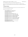
7.4 Event Viewer
The Windows event log (application log) shows information such as status displays regarding layer 1/2 as
well as various information and error messages.
Possible entries in the Windows event log:
• MessageId=1000, DST service was started, version
• 1MessageId=1001, DST service start failure, code
• MessageId=1010, capi2032.dll failure, code
• MessageId=1011, Capi version
• MessageId=1012, Capidrv version
• MessageId=1013, Speech-Design ISDN driver version
• MessageId=1020, Controller 1: Layer 1 NT, red alarm (to PBX)
• MessageId=1021, Controller 1: Layer 1 TE, red alarm (to NT)
• MessageId=1022, Controller 1: Layer 1 NT, yellow alarm (to PBX)
• MessageId=1023, Controller 1: Layer 1 TE, yellow alarm (to NT)
• MessageId=1024, Controller 1: Layer 1 NT, line up (to PBX)
• MessageId=1025, Controller 1: Layer 1 TE, line up (to NT)
• MessageId=1030, Controller 1: Layer 2 NT, link established (to PBX)
• MessageId=1031, Controller 1: Layer 2 TE, link established (to NT)
• MessageId=1032, Controller 1: Layer 2 NT, link released (to PBX)
• MessageId=1033, Controller 1: Layer 2 TE, link released (to NT)
• MessageId=1081, File access failure:
• MessageId=1089, Internal failure text:
• MessageId=1098, DST service was stopped by system shutdown
• MessageId=1099, DST service was stopped
37/63
MobilePro-Anschalte-Installations-Handbuch_4_2_13_EN
Example:
Example: View after double-clicking "{i} Information":
38/63
10/19/09 16:23:19
MobilePro-Anschalte-Installations-Handbuch_4_2_13_EN
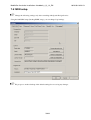
7.5 ISDN setup
Change the following settings only after consulting with Speech Design Service.
Using the link ISDN setup (Desktop/ISDN setup), you can change Capi settings.
We propose to make a backup of the default settings bevore saving any changes.
39/63
10/19/09 16:23:19
MobilePro-Anschalte-Installations-Handbuch_4_2_13_EN
10/19/09 16:23:19
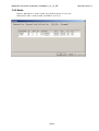
7.5.1 Reducing the number of controllers
Example: Mobile Pro 60/160
Here, you can check the boxes to define which settings have to be active. Depending on the Mobile Pro
model, this varies between 2 rows (for Mobile Pro 30/80 and Mobile Pro 30/500) and 16 rows (for Mobile Pro
8/8). The row number corresponds to the physical controller number (refer also to [#RJ45-Buchsen Rear side
of the Mobile Pro]). There may not be any gaps between the rows.
40/63
MobilePro-Anschalte-Installations-Handbuch_4_2_13_EN
10/19/09 16:23:19
In the following example, an Mobile Pro 60/160 becomes an Mobile Pro 30/160 by changing the
configuration as outlined below. The handling with Mobile Pro 4/4 and Mobile Pro 8/8 is correspondingly.
As shown below, deactivate the last 2 boxes (corresponds to 2 ISDN controllers) and change the text in rows 2
and 8 of the "Name" column to "to PBX".
Then, set the operating mode NT under the ISDN tab in the Endpoint column, in rows 2.
41/63
MobilePro-Anschalte-Installations-Handbuch_4_2_13_EN
10/19/09 16:23:19
The example procedure described above reduced the original 2 ISDN controllers in the direction of the trunk
and in the direction of the PBX to a reduced version with 1 ISDN controllers in the direction of the trunk and
in the direction of the PBX.
The Public services section shows the modified configuration of the example as a physical structure.
Controllers 2 to 16 are marked as disabled and are not to be connected to cables. Refer also to [#Controller
configuration Controller configuration]
We recommend maintaining the sequence TE followed by NT.
42/63
MobilePro-Anschalte-Installations-Handbuch_4_2_13_EN
7.5.2 Assigning the B-channels
Here, the settings for assigning the B-channels are described in the configuration file.
43/63
10/19/09 16:23:19
MobilePro-Anschalte-Installations-Handbuch_4_2_13_EN
10/19/09 16:23:19
These settings are relevant on the NT side only if a "mixed" (incoming/outgoing) B-channel assignment is
active.
The B-channels are numbered from 1 - 31.
With the fields "BchanInMin" and "BchanInMax" B-channels for incoming calls are used.
With the fields "BchanOutMin" and "BchanOutMax" B-channels for outgoing calls are used.
With the fields "BchanBiMin" and "BchanBiMax" B-channels for both directions are used.
For the assignment, the B-channels for the respective direction are used first. If no more B-channels are
available in this pool, the Bi-channels (bidirectional) are used. If none of those are available either, no
connection is possible.
Scheduling Modes (BchanInSched BchanOutSched)
Up_Count
B-channels are assigned in an order from Min to Max.
Down_Count B-channels are assigned in an order from Max to Min.
Up_Round
B-channels are used in upward sequence.
The start is not always with Min.
Down_Round
B-channels are used in downward sequence.
The start is not always with Max.
44/63
MobilePro-Anschalte-Installations-Handbuch_4_2_13_EN
7.5.3 Media
• Ensure "Data Mode" is in the column, and "TX Transparent" in every row.
• Ensure that "SW" is in the column, and "HW" in every row.
45/63
10/19/09 16:23:19
8 Public Services
Get to Public Services via the login level "Public":
• From here you can transfer Mobile Pro files (Backups, Logfiles, Traces, etc.) to your PC. Up- and
downloads are available via the Filemanager of Mobile Pro.
• Select Controller-configuration to get a simplified diagram of the Mobile Pro ISDN-Setup settings
(rear side of Mobile Pro):
♦ Kind of direction (TE,NT)
♦ Programming of the controller
◊ activ (green)
◊ passiv (red)
46/63
9 IT security
For security reasons, only the following ports are permitted for use:
Software module
Version
TCP port UDP port
Apache web server with PHP module
1.3.35 (PHP 4.3.2) 80
realVNC remote maintenance software
4.0
80
5800,5900 -
DNS
53
POP3
110
9.1 Release further Ports
In LAN Eigenschaften -> TCP/IP -> Erweitert -> Option -> Eigenschaften -> TCP/IP Filtering further
ports can be added.
47/63
10 Numbering plan - detail
10.1 Simplified diagram
10.1.1 Numbering plan for incomming calls
The format of the CalledNum and the CallingNum which is transmitted to the Mobile Pro system is depending
on what kind of connection the system is connected. Example: the system can be connected between trunk and
PBX (=call through) or the system is connected as sub-PBX (behind the PBX via ISDn or SIP). Therefore all
numbers have to be transformed into a definite numbering format which is the international format for
telephone numbers (E.164). All numbers (User number, forwarding target numbers, .....) have to be set in this
format.
Example:
367
-> 4989458367
0171317317
-> 49171317317
0043891233343 -> 43891233343
10.1.2 Numbering plan for dialling and grafical user input (GUI)
Using the international standard format E.164 ease the programming of the settings in the WEB-interface.
Example: For "Dialing from main menu" just enter the extension number for internal call (e.g. 317) or the
number of an external call. The programmed rule ensures that the numbers are transmfored automatically in
the right ("complete") number.
48/63
MobilePro-Anschalte-Installations-Handbuch_4_2_13_EN
10/19/09 16:23:19
Example:
317
-> 4989458317
0170317317 -> 49170317317
10.1.3 Numbering plan for outgoing call
To enable outgoing calls it is also important to programm all telephone numbers (CalledNum and
CallingNum) based on the E.164 format. Also the direction of calls are relevant for the programming.
Example:
4989458317 -> 317 //
4969123456 -> 069123456
43891233343 -> 43891233343,!Type Of Number = International
10.1.4 Simplified diagram of the transform-rules
For every kind of possible number transformation a single numbering plan has be generated. The quantity of
numbering plans are not limited. The numbering plan has a Filter and Generator. The generator uses the
filter which fits the best for numberting transformation (Best Match).
The transform-rules need following numbers:
1. Numbering plan for incoming
calls
2. Numbering plan for dialling and
GUI
3. Numberig plan for outgoing
calls
incoming CalledNum
dialing/input
outgoing CalledNum
incoming CallingNum
-
outgoing CallingNum
Example: (Numbering plan for incoming calls/Called)
Legend:
• NAME: Free text
• DIR: PBX | Trunk // Direction from where a calls is coming/is going. If field is empty the direction is
not relevant.
• INITIATOR: Is used for dialing and input. It is option to use the Initiator as additional filter. If the
field is empty the initiator is not relevant.
• DIGITS: Every number begins with a search pattern (to be read from left to right).
In special cases you have to programm 't' for call termination with timeout (without hash #). Example
for an entry: t0 or t00
49/63
MobilePro-Anschalte-Installations-Handbuch_4_2_13_EN
10/19/09 16:23:19
• TON: type of number // u = unknown, s = subscriber, n = national, i = international
• MINLEN: Minimum length of number. Empty fields are not valued.
• MAXLEN: Maximum length of number. Empty fields are not values.
• STRIP: Number (quantity) of digits which are removed left from the telephone number. The removed
digits are saved for further processing in variables '$n'. It is also possible to remove digits repeatedly,
in order to save them in several variables
Example: Nummer='1234567', Strip= '2,3' -> Variable $1='12' Variable $2='345'. The number itself is
reduced to '67'
• INSERT: Pattern, which is always added on the left side of the number. Here, also the variables '$n'
can be added.
Entry and diagram of transform ruels
Within the menu "Numbering plan" (in "System administration") you find the menu ">>Individual Settings".
Here the transform rules can be edited. If you enter a new rule, the table only shows the fields which are
constitutive for the rule.
10.1.5 Plans
10.1.5.1 Numbering plan for incoming rules
On page incomingNumberingPlan the Lists for Called and Calling are shown.
In Step2 you can test the plans. (Input: CalledNum, CallingNum,Dir... Output: CalledNum, CallingNum,
Ton...).
For each Called and Calling an own list.
• List
• Link: Add
50/63
MobilePro-Anschalte-Installations-Handbuch_4_2_13_EN
• Form
Description
Typ
Default / Value allowed input
NPNNAME
text
empty
Dir
select see *DIR
Digits
text
empty
alnum
digit
Type Of Number select see *TON
51/63
10/19/09 16:23:19
MobilePro-Anschalte-Installations-Handbuch_4_2_13_EN
MinLen
text
empty
digit
MaxLen
text
empty
digit
Strip
text
empty
digit
Insert
text
empty
digit
10/19/09 16:23:19
> Enter the values into the fields accordingly
10.1.5.2 Numbering plan for outgoing calls
On page outgoingNumberingPlan the Lists for Called and Calling are shown.
In Step2 you can test the plans.(Input: CalledNum, CallingNum,Dir... Output: CalledNum, CallingNum,
Ton...).
Outgoing Called
• List
• Link: Add
52/63
MobilePro-Anschalte-Installations-Handbuch_4_2_13_EN
• Form
Description
Typ
Default / Value allowed input
NPNNAME
text
empty
alnum
Digits
text
empty
digit[*#+]
Strip
text
empty
digit
Insert
text
empty
digit
Type Of Number select see *TON
digit
Dir
digit
select see *DIR
> Enter the values into the fields accordingly
Outgoing Calling
• List
53/63
10/19/09 16:23:19
MobilePro-Anschalte-Installations-Handbuch_4_2_13_EN
10/19/09 16:23:19
• Link: Add
• Form
Default / Value |<: bgcolor="#e0e0e0"> allowed input
Description
Typ
NPNNAME
select List from NPNAME(outgoing Called )
Dir
select see *DIR
Digits
text
empty
digit[*#+]
Strip
text
empty
digit
Insert
text
empty
digit
Type Of Number select see *TON
alnum
digit
10.1.5.3 Numbering plan for dialling and grafical user input (GUI)
On page dialing/inputNumberingPlan the Lists for dialing and input are shown.
Here you create the numbering plans, which are used for 'Dialing from main menu' and for the 'entry of
numbers on the WEB-interface' (also for update and restore < 4.1 ).
In Step2 you can test the plans. (Input: Initator, Number Output: Number).
• List
• Link: Add
54/63
MobilePro-Anschalte-Installations-Handbuch_4_2_13_EN
• Form
Description Typ
Default / Value
allowed input
NPNNAME select List from NPNAME(outgoing Called )
alnum
Initiator
text
empty
digit
Digits
text
empty
digit[*#+]
MinLen
text
empty
digit
MaxLen
text
empty
digit
Strip
text
empty
digit
Insert
text
empty
digit
> Enter the values into the fields accordingly
• Attachment:
55/63
10/19/09 16:23:19
MobilePro-Anschalte-Installations-Handbuch_4_2_13_EN
10/19/09 16:23:19
*DIR
Default Value
empty
empty
PBX
PBX
Trunk
Trunk
*TON
Default
Value
empty
empty
unknown
u
subsciber
s
national
n
international i
10.1.6 Mixed Extension lengths and "Function numbers with DTMF redialling"
Within the menu "Numbering plan" (in "System administration") you find the menu ">>Individual Settings".
Here the transform rules can be edited. If you enter a new rule, the table only shows the fields which are
constitutive for the rule:
Mixed Extension lengths and "Function numbers with DTMF redialling
Example for function number "Callback": Basically, in this example two numbers are combined in one. The
function number for Callback is -900; the user number is -101. The system dials [89458]900101, which is
498989458900 for function callback and 498989458101 (user number). If the extension numbers of the
company have all the same length, the Wizar creates following rule (see below). If the extensions have
different lengths, you have to enter the highest length (example 3 digits):
• Digits: 89458
• Minlen: 11
• Maxlen: 11
• Strip: 5,3
• Insert: 498989458$2498989458
Strip 5,3 removes the first 5 digits "89345" and the next 3 digits "900".
If the function number has just 2 digits and/or the user number has 2 digits, the rule will not work anymore
because Minlen and Strip are wrong.
Therefore, if the extension numbers of the company have different lengths Minlen, Maxlen and Strip have to
be adjusted.
Example 1: 2- and 3-digit extensions. The function number has 2 digits:
• Digits: 89458 // no change
• Minlen: 9 // Length of PBX number(5) + Length of function number(2) + Length of shortst user
number(2)
• Maxlen: 10 // Length of PBX number(5) + Length of function number(2) + Length of longest user
number(3)
• Strip: 5,2 // Length of PBX number(5), Length of function number(2)
56/63
MobilePro-Anschalte-Installations-Handbuch_4_2_13_EN
10/19/09 16:23:19
Example 2: 2, 3 and 4-digit extensions. The function number has 4-digits.
• Digits: 89458 // no change
• Minlen: 11 // Length of PBX number(5) + Length of function number(4) + Length of shortst user
number(2)
• Maxlen: 13 // Length of PBX number(5) + Length of function number(4) + Length of longest user
number(4)
• Strip: 5,4 // Length of PBX number 5),Length of function number(4)
57/63
11 Troubleshooting
For troubleshooting purposes, the following software tools are provided on the Mobile Pro Desktop:
Tool
Purpose
"Voice IV Server"
Monitoring and tracing tool
"Mobile Pro Reset"
Ist kein WEB-Zugang möglich (z.B. Passwort vergessen),
kann der RESET (Auslieferzustand) über
„Mobile Pro-Reset“ auf dem Desktop ausgeführt werden.
Dieser Link funktioniert nur vom localhost aus.
"Event Viewer" via My Computer -> Manager
Status displays regarding layers 1/2
Almost all of these software tools have their own onscreen help.
58/63
12 FAQs
For answers to frequently asked questions, visit:
http://www.speech-design.com/de/Partner/Login
59/63
13 Uninstalling the Mobile Pro
Bei einem Abbau des Systems beachten Sie bitte folgende Schritte:
>
Make a data backup by creating a backup file (Mobile Pro web interface >>Backup). Save the backup file
to an external medium (such as a USB stick).
>
Then, to restore the system to its factory settings, carry out a reset (Mobile Pro web interface >> Reset).
This deletes all settings and saved data.
> Press the lock switch of the switch box to disable it.
The PBX is now connected directly to the NT.
> Disconnect the cables between the Mobile Pro and the switch box.
> Shut down the system.
>
To uninstall the switch box, disconnect the remaining cables from the switch box (to NT and to PBX) and
restore the original connection between the NT and PBX.
> After the uninstallation, return all cables along with the system.
60/63
14 Final decommissioning
The Mobile Pro contains electronic components that must be disposed of properly.
> Therefore, after final decommissioning of the unit, give it over to an electronics recycling facility.
61/63
15 Technical data
Type of construction
19-inch rack-mounted unit, 3 HU
Environmental temperature
while storage:
in operation:
0 up to 40°C
+15°C to +45°C
Environmental humidity
while storage and in operation :
15%-95% relative humidity
Connections
Mobile Pro 30/80 (PRI)
Mobile Pro 30/500 (PRI)
Mobile Pro 60/160 (PRI)
Mobile Pro 60/500 (PRI)
Mobile Pro 4/4 (BRI)
Mobile Pro 8/8 (BRI)
2 x PRI connections - 30 in, 30 out, 80 user
2 x PRI connections - 30 in, 30 out, 500 user
4 x PRI connections - 60 in, 60 out, 160 user
4 x PRI connections - 60 in, 60 out, 500 user
8 x BRI connections - 8 in, 8 out, 25 user
16 x BRI connections - 16 in, 16 out, 35 user
Power supply
Weight
Mobile Pro 30/80
Mobile Pro 30/500
Mobile Pro 60/160
Mobile Pro 60/500
Mobile Pro 4/4
Mobile Pro 8/8
Switch-Box:
Power supply to Switch-Box
Subpackage(cable)
Mobile Pro 30/30:
Mobile Pro 60/60:
Mobile Pro 4/4:
Mobile Pro 8/8:
230 VAC
50-60 Hz
Power input max.: 150W
ca. 8,5 kg (3 HE)
ca. 8,6 kg
.....
.....
.....
.....
ca. 0,33 kg
ca. 0,1 kg
ca. 0,8 kg
ca.2 kg
.....
.....
Dimensions (width, height, depth) (3 HU) 483 mm (with front panel) / 133 mm / 430 mm
LAN
10/100 Base-T Ethernet
62/63
16 GLOSSARY
Browser
Program for viewing websites (e.g. Internet Explorer or Firefox).
DHCP
Dynamic Host Configuration Protocol; A protocol that allows a device in the network to
assign an IP address to other devices in the network, either when the connection is
established or at another time.
IP
Internet Protocol; defines how devices in a data network communicate with each other.
IP address
Address of a device in a network that corresponds to the specifications of the Internet
Protocol.
LAN
Local Area Network.
63/63