1
WS-PGRADE Portal
User Manual
Version 3.6.5
20 June, 2014
by Gábor Hermann and Tibor Gottdank
Docs for User Series
WS-PGRADE PORTAL
USER MANUAL
WS-PGRADE PORTAL
COOKBOOK
WS-PGRADE Portal User Manual
Copyright 2007-2014 MTA SZTAKI LPDS, Budapest, Hungary
MTA SZTAKI LPDS accepts no responsibility for the actions of any user. All users accept full responsibility for
their usage of software products. MTA SZTAKI LPDS makes no warranty as to its use or performance.
The gUSE/WS-PGRADE is an open source software.
MTA SZTAKI LPDS inspires and supports to take the whole gUSE/WS-PGRADE community into the developing
work.
1
WS-PGRADE Portal User Manual
Table of Contents
About this Manual ......................................................................................................................................... 6
How this Manual is Organized ....................................................................................................................... 6
Release Notes ................................................................................................................................................ 6
I. Main Part .................................................................................................................................................. 21
Introduction............................................................................................................................................. 21
1. Graph ................................................................................................................................................... 23
1.1 The Acyclic Behavior of the Graph ................................................................................................ 24
1.2 The Graph Editor ........................................................................................................................... 24
2. Jobs ...................................................................................................................................................... 26
Introduction ......................................................................................................................................... 26
2.1 Algorithm ....................................................................................................................................... 27
2.2 Resource of Job Execution............................................................................................................. 37
2.3 Port Configuration ......................................................................................................................... 39
2.4 Extended Job Specification by JDL/RSL ......................................................................................... 49
2.5 Job Configuration History .............................................................................................................. 50
2.6 Job Elaboration within a Workflow ............................................................................................... 50
3. Workflows and Workflow Instances.................................................................................................... 60
3.1 Methods of Workflow Definition .................................................................................................. 62
3.2 Workflow Submission .................................................................................................................... 66
3.3 Workflow States and Instances ..................................................................................................... 67
3.4 Observation and Manipulation of Workflow Progress.................................................................. 68
3.5 Fetching the Results of the Workflow Submission ........................................................................ 70
3.6 Templates for the Reusability of Workflows. ................................................................................ 71
3.7 Maintaining Workflows and Related Objects (Up-, Download and Repository) ........................... 74
4. Access to the gUSE Environment......................................................................................................... 78
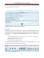
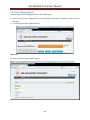
4.1 Sign in the WS-PGRADE Portal ...................................................................................................... 78
4.2 Overview of the Portlet Structure of the WS-PGRADE Portal ....................................................... 78
5. Internal Organization of the gUSE Infrastructure – Only for System Administrators ......................... 80
6. Resources ............................................................................................................................................ 82
6.1 Introduction ................................................................................................................................... 82
2
WS-PGRADE Portal User Manual
6.2 Resources ...................................................................................................................................... 83
7. Quota Management – Only for System Administrators .................................................................... 102
8. SHIWA Explorer ................................................................................................................................. 103
9. WFI Monitor ...................................................................................................................................... 105
10. Text Editor – Only for System Administrators ................................................................................. 106
11. Collection and Visualization of Usage Statistics .............................................................................. 107
12. User Management ........................................................................................................................... 111
13. Debugging of Job Submissions by Breakpoints ............................................................................... 119
Breakpoint definition as a part of the Job Configuration .................................................................. 119
Workflow submission in debugging state ......................................................................................... 121
14. Defining Remote Executable and Input ........................................................................................... 128
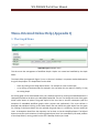
Menu-Oriented Online Help (Appendix I) ................................................................................................. 130
1. The Graph Menu................................................................................................................................ 130
2. The Create Concrete Menu ............................................................................................................... 133
3. The Concrete Menu ........................................................................................................................... 134
3.1 The Concrete/Details Function .................................................................................................... 135
3.2 The Concrete/Configure Menu.................................................................................................... 138
3.3
4.
The Concrete/Info Function .................................................................................................. 164
The Template Menu ...................................................................................................................... 165
4.1 The Template/Configure Function .............................................................................................. 167
5. The Storage Menu ............................................................................................................................. 168
6. The Upload Menu .............................................................................................................................. 170
7. The Import Menu .............................................................................................................................. 171
8. The Notification Menu ...................................................................................................................... 175
9. The End User Menu ........................................................................................................................... 178
10. The Certificates Menu ..................................................................................................................... 184
10.1 Introduction ............................................................................................................................... 184
10.2 Upload ....................................................................................................................................... 185
10.3 Creating a Proxy Certificate ....................................................................................................... 188
10.4 Credential Management............................................................................................................ 189
11. The Concrete/Export Menu ............................................................................................................. 191
12. Public Key Menu .............................................................................................................................. 196
3
WS-PGRADE Portal User Manual
13. LFC Menu ......................................................................................................................................... 198
14. Internal Services Group ................................................................................................................... 209
14.1 Component Types...................................................................................................................... 209
14.2 Components .............................................................................................................................. 210
14.3 Services ...................................................................................................................................... 212
14.4 Copy Component Properties ..................................................................................................... 213
15. The Assertion Menu ........................................................................................................................ 214
16. The EDGI-based Functions............................................................................................................... 217
17. Job Submission to Cloud by the CloudBroker Platform .................................................................. 219
17.1 Registration ............................................................................................................................... 219
17.2 Configuration ............................................................................................................................. 220
17.3 The CloudBroker Billing menu ................................................................................................... 225
18. Job Submission to Cloud by Direct Cloud Access Solution .............................................................. 231
19. Configuration of REST Services ........................................................................................................ 234
About REST Services .......................................................................................................................... 234
19.1 REST Service Configuration........................................................................................................ 234
20. Robot Permission Usage .................................................................................................................. 237
21. Data Avenue .................................................................................................................................... 243
22. Desktop Grid Access from WS-PGRADE .......................................................................................... 250
23. SHIWA Submission Service Usage in WS-PGRADE .......................................................................... 251
Main Terms and Activities in the WS-PGRADE Portal (Appendix II).......................................................... 258
Jump Start in the Development Cycle (Appendix III)................................................................................. 260
Introduction........................................................................................................................................... 260
1. Creating the Graph of the Workflow ................................................................................................. 260
2. Creating the Workflow ...................................................................................................................... 260
3. Configuring the Created Workflow ................................................................................................... 261
4. Obtaining of a Valid Proxy Certificate ............................................................................................... 262
5. Checking the Configuration ............................................................................................................... 262
6. Submitting the Workflow .................................................................................................................. 263
7. Controlling the Progress/Termination of the Submitted Workflow ................................................. 263
7.1 Observing the details of a workflow instance: ............................................................................ 263
7.2 Observing the details of Job instances ........................................................................................ 263
4
WS-PGRADE Portal User Manual
7.3 Access of files belonging to a job instance .................................................................................. 263
Workflow Interpretation Example (Appendix IV)...................................................................................... 264
5
WS-PGRADE Portal User Manual
About this Manual
The gUSE/WS-PGRADE User Manual is a detailed guide and description of WS-PGRADE Portal at user
level. The WS-PGRADE Portal, developed by Laboratory of Parallel and Distributed Systems at MTA
SZTAKI, is a web portal of the grid and cloud User Support Environment (gUSE). It supports development
and submission of distributed applications executed on the computational resources of various
distributed computing infrastructures (DCIs) including clusters (LSF, PBS, MOAB, SGE), service grids (ARC,
gLite, Globus, UNICORE), BOINC desktop grids as well as cloud resources: Google App Engine,
CloudBroker-managed clouds as well as EC2-based clouds.
How this Manual is Organized
This Manual has the following structure:
1. The Main Part which comes directly after the Release Notes, explains the basic concepts and
terms to use WS-PGRADE portal. This section covers the ultimate element of WS-PGRADE usage.
2. The Menu-Oriented Online Help introduces the practical use of WS-PGRADE menus and
functions.
3. The third section, the Jump Start in the Development Cycle gives you a big picture about the
workflow configuration and submission process (if you search for detailed description of various
job configuration and submission, download and use the WS-PGRADE Cookbook)
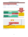
The document uses light purple color for notifications and light orange for pitfalls and warnings.
Release Notes
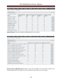
Release Notes to Version 3.6.5
The only one but important change in this version is the improvement of EC2-based direct cloud access.
This modified solution is more comfortable to use, the administrators don’t need to install Euca2ools to
prepare master DCI Bridge and the users can use more cloud services from one portal by this solution.
More details:
in chapter 18 within Menu-Oriented Online Help
in section 5.19 within DCI Bridge Manual
in chapter VI within Admin Manual.
Release Notes to Version 3.6.4
The main improving in version 3.6.4 is to support the job submission by the SHIWA Submission Service.
The web service based SHIWA Submission Service replaces the old GT4-based GEMLCA Service and
enables execution of workflows based on different workflow engines. Therefore you can use in WS6
WS-PGRADE Portal User Manual
PGRADE various workflows from various communities developed in various engines. All of these
workflows are stored in the central workflow repository (called SHIWA Workflow Repository). Workflows
have been stored in the SHIWA Workflow Repository can be explored by several ways, for example the
WS-PGRADE offers for workflow browsing a runtime built-in look up tool, the SHIWA Explorer. (You find
related user-level documentation in chapter 8 within Main part, in chapter 23 within the Menu-Oriented
Online Help, administrative information in chapter 2.10 of DCI Bridge Manual as well as in chapter VIII of
Admin Manual.)
Other changes:
From this release the DCI Bridge handles HTTPS-based inputs and outputs beside HTTP-based
I/O. (You can read about the Additional Settings in case of Not Trusted Certification in chapter IX
within Admin Manual.)
From this version the CloudBroker entities (exactly: the wrapper applications that run
executables) are identified by ID instead of names. This change affects the CloudBroker-based
middleware setting in case of applying own wrapper.
Additional minor bug fixes are in CloudBroker portlet development, in error log handling
(SourceForge bug report: #218) and in Data Avenue portlet development, in download function.
Solving the next problem: Callback functionality marks successful jobs as error jobs (SourceForge
bug report: #222)
Improved Install Wizard tool: fixes a number of class loading issues, enables using already
available databases for the deployment.
Finally, an important improvement is the Single Job Wizard, a new development based on gUSE/ASM API
for simplifies workflow creation and execution in the simplest case, if the workflow contains one job
only. This web application is not a part of gUSE 3.6.4 package but a separate solution of ASM. (All related
information about Single Job Wizard can be found at ASM menu of gUSE SourceForge site:
https://sourceforge.net/p/guse/asmsp/wiki/Single%20Job%20Wizard/ and a short description in chapter
X. within Admin Manual)
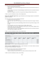
Release Notes to Version 3.6.3
The release 3.6.3 of gUSE contains three main changes:
First of all, there are more improvements in the file commander called Data Avenue first released in
version 3.6.0:
Capability of automated user ticket generation to use Data Avenue within portals
Admin ticket request form (see details about admin ticket request in chapter VII within the Admin
Manual)
Support for S3 protocol
Changes in Favorite settings as well as minor changes in design
Improved file upload
Changes in backend (in Data Avenue blacktop service):
7
WS-PGRADE Portal User Manual
Security improvements: in-memory credentials, alias credentials are now encoded and
deleted on expiration
Use of JSAGA version 1.0.0
Interface naming made conform to OGSA-DMI
Improved logging
Bug fixes
More about Data Avenue you find in chapter 21 within Menu-Oriented Online Help as well as in
chapter VII of Admin Manual.
The two other developments come from the gUSE community (from Ruđer Bošković Institute, Zagreb
and from Eberhard Karls University, Tübingen): the supported cluster set enriched by the
development of submitters to SGE (Sun Grid Engine) and MOAB clusters. The configuration and
operation of both submitters is very similar to PBS and LSF. (Details: Portal User Manual - chapter
6.2.20 and chapter Public Key; DCI Bridge Manual – chapter 2.7 and 2.19.)
There is a change in logging mechanism of gUSE as well: from this version the logging is possible with
Apache log4j. By the application of log4j is the debugging and troubleshooting of gUSE components
will be easier by the developers and administrators. (See details in chapter Logging with log4j within
the Additional Enhancement of Admin manual.)
Additionally, this release is also includes a bug fixing: the solving of UNICORE jobs problem - these
jobs didn’t work with XtreemFS remote ports earlier (SourceForge bug report: #211).
Release Notes to Version 3.6.2
There are more changes in release 3.6.2:
The main improvement in this version is the solution of direct cloud access. By this development
the user can easily submit jobs directly to the cloud without any brokering support. To this the
user just need to own and use valid authentication data received from cloud provider. (See
details in Chapter 18 within the Menu-Oriented Online Help as well as in chapter 6.) However,
there is needed some preliminary administration tasks for proper using of direct cloud access.
(About these tasks and additional considerations you find details in chapter VI of Admin Manual
and in chapter 2.18 of DCI Bridge Manual.)
Another relevant change is the solution of remote definition and using of executables. This new
feature of WS-PGRADE job configuration enables users to add remote URL of the executable.
(The local uploading of executables was only supported earlier.) Additionally, the supported
protocol set to define remote sources of inputs is extended as well. (See details in chapter 14.)
An additional minor change: the unnecessary temporary files will be automatically deleted from
directories of WS-PGRADE and WFI components after saving workflow configuration as well as
after workflow submission.
Further bug fixes:
8
WS-PGRADE Portal User Manual
Solving the job saving problem in case of CloudBroker (SourceForge bug report: #121).
Adding missing messages in case of CloudBroker (SourceForge bug report: #123).
Solving the lost arguments problem in case of CloudBroker job configuration (SourceForge bug
report: #134).
Bug fixing by the UNICORE gUSE community: it solves the problem of UNICORE submitter that
generates incorrect number of cores (SourceForge bug report: #192).
Release Notes to Version 3.6.1
The main improvement in gUSE v3.6.1 is the solution for debugging of job submissions by applying
breakpoints in WS-PGRADE workflows. By this tool the users can interact with workflows at runtime:
they can directly influence and change workflow’s submission processes and results by enabling or
prohibiting the progress of job instances at breakpoints (for more details see chapter 13).
From this version the Graph Editor can be used with the latest Java upgrade (Java 1.7.0_45) as well.
Additionally, a minor change is a bug fixing (related bug report on SourceForge: #184): The
(jobtype=single) will be set in GT5 RSL, when the property "Kind of binary:" is configured to "Sequential".
Release Notes to Version 3.6.0
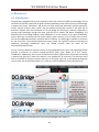
The main change in this version is a developed tool called Data Avenue that integrated the function of
Data Avenue web service as a new portlet into WS-PGRADE portal. Data Avenue is a useful file
commander for data transfer, enabling easy data moving between various storages services (such as
grid, cloud, cluster, supercomputers) by various protocols (HTTP, HTTPS, SFTP, GSFTP, SRM). The using of
Data Avenue is similar to other well-known file commanders (e.g. Total Commander or Midnight
Commander): you can use a simple two-panel (source and destination) form to copy, delete, download,
upload etc. (for more details see chapter 20 within Menu-Oriented Online Help).
And one more new development: the overall billing and pricing information menu (CloudBroker Billing)
in WS-PGRADE to support the CloudBroker-specific (pay-per-use) job submission (for more details see
chapter 17.2 within Menu-Oriented Online Help).
Minor changes, bug fixes and other error solving to feature requests:
Integrated DCI Bridge: a common bridge instance may support gLite and UNICORE.
voms-proxy-certificate expiration time (“Proxy Valid”) option can be set for each gLite VO in the
DCI Bridge.
Workflow name length limitation to 250 characters is checked (SourceForge bug report: #169).
Admin can set default JDL parameters for the VOs.
Extension the effect of the Delete all instance command to the workflow instances being in
“suspended” status.
Fixing the problem of the workflow submission related automatic email notification.
Fixing the problem that the DCI_BRIDGE did not forward the abort requests of the user toward
the DCIs in some cases.
9
WS-PGRADE Portal User Manual
Solving the problem that a job might show false “running” state in case of the missing public key
on the remote PBS resource (SourceForge bug report: #167)
Correcting the values of the “Debug mode” in the “Settings” pane of the DCI Bridge (SourceForge
bug report: #170).
Correcting the problem that the creation of a workflow may fail without proper error message
(SourceForge bug report: #161).
Correcting the problem of the missing error message in the case of a missing PBS connection
(#132).
Correcting a problem experienced when the free input port of a job was connected to the result
of a database query (SourceForge bug report: #77).
Correcting the file size limit extension problem: WS-PGRADE warns if the size of the file to be
uploaded is larger than the configured maximum (SourceForge bug report: #71).
Correcting the problem that LFC portlet might use invalid certificates after registering of an
internal server (SourceForge bug report: #15).
New JDL tags supporting a different kind of MPI submission: If the user wants to avoid the
obligatory running of the standard “mpirun” then she defines her job as “normal” instead “MPI”
and in the JDL extension of the job definition describes the needed parameter by the new
tags “SMPGranularity” and “CPUnumber” (SourceForge bug reports: #47, #53, #55, #56).
Release Notes to Version 3.5.8
The major improvement in version 3.5.8 is the internal system performance optimization for job
execution. This internal reorganization of exchanging information between WS-PGRADE and the various
gUSE components significantly increases the performance of WS-PGRADE portal. The changes mainly
concern the background processes, only two minor visual changes appears on portal user interface: in
Workflow/Concrete/Details function and in Storage function (the updated description of this two parts of
the portal you can see in chapter 3.1 and 5 within section Menu-Oriented Online Help).
Other changes:
The administrative configuration of Remote API is easier than earlier: you can set it in the WSPGRADE portal. (See the details about the Remote API configuration and usage in
RemoteAPI_Install_Manual.pdf and in RemoteAPI_Usage.pdf. You can also find some examples
for using Remote API in the RemoteAPI_Usage_Examples.zip in the Documentation folder.)
The maximum quota size belonging to a portal user for workflow is increased to 10000 MB (the
earlier limit was 5000 MB). About the quota setting see chapter The Internal Services in the
Administrator Manual.
In the new version (v3.4.5) of ASM new features were implemented (getting/setting resource of
a job; getting/setting number of input files uploaded as paramInputs.zip; setting remote output
path for a given output port; getting content of an input file). The ASM v3.4.5 is compatible with
gUSE from version 3.5.8, and not compatible with older versions. (For upgrading from v3.4.4 to
v3.4.5 see the Portal_Upgrade_Manual_v3.5.8.pdf. You can find more details about ASM usage
in the ASM_Developer_Guide_v3.4.5.pdf.)
Additionally, this release comes with more error fixings. The whole list:
10
WS-PGRADE Portal User Manual
-
Error fixing of Suspend all button functionality (bug number on gUSE SourceForge: #139)
Error fixing of Suspend button (bug #138)
Solving of WFI monitor error (bug #130)
Installation error fixing in version 3.5.3 (bug #107)
Problem solving of paramInputs.zip file (bug #95)
Problem solving in output transfer between two jobs (bug #84)
Error fixing of Delete Old Instances option (bug #82)
Problem solving the low level of user quota (bug #81)
Solving the vulnerability problem in cross scripting (bug #78)
Bug fixing of live file generation from database (bug #77)
Error fixing of BOINC jobs error status information (bug #144)
Problem solving in configuring “binaries” for REST middleware (bug #142)
Bug fixing of filtering during add operation of GT2 resource (bug #141)
Problem solving of disturbing line separators in public key (bug #131)
Solving the gLite-based remote file opening problem (bug #128)
Fixing the visibility of the Security/CloudBroker menu for power- and end users. (bug #148)
Error fixing in resubmission of aborted LSF jobs (bug #159)
Solving the too short proxy lifetime problem (bug #125)
ASM-specific bug fixings (bug #164 and #165)
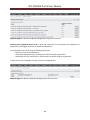
Release Notes to Version 3.5.7.1
In gUSE/WS-PGRADE version 3.5.7.1 all the patches of 3.5.7 are applied, and additionally, the following
bugs are fixed:
Uploading via LFC portlet (list of available storage elements is empty) (bug #143)
Providing proper version in a SHIWA Bundle to be exported (mentioned in bug #149)
Filtering of importable SHIWA bundles (bug #147)
Release Notes to Version 3.5.7
The main change in gUSE/WS-PGRADE version 3.5.7 is the fast statistical data processing and providing
mechanism in Statistics function that loads the gUSE database at lower level than earlier and exploits the
resources more effectively than in the previous gUSE versions (see chapter 11 to read more about
Collection and Visualization of Usage Statistics).
Additionally, the following bugs are fixed:
GEMLCA-based default input file error fixing (bug number on gUSE SourceForge: #135)
Bug fixing in output files downloading from Storage/Local (bug #89)
Solving of disappearing problem of workflows, graphs, and storage after restart (bug #87)
Solving of minor issue after a refresh of graph list (bug #69)
11
WS-PGRADE Portal User Manual
Release Notes to Version 3.5.6
The main improvement in version 3.5.6 is the development in WS-PGRADE workflow export/import
to/from Remote SHIWA Repository. From this version you can share your workflow to SHIWA project
community in WS-PGRADE format and in SHIWA IWIR format as well (the latter solution is useful if you
want to use your workflow by other workflow management systems than WS-PGRADE. However, for
successful sharing, before in IWIR format export – unlike in WS-PGRADE format - your workflow can fit
some rigorous preliminary conditions. For details see chapter 11 in Menu-Oriented Online Help.).
Therefore the shared workflows can be imported from remote repository to WS-PGRADE portal
environment in well-known WS-PGRADE implementation format or in IWIR format. (For details see
chapter 7 and 11 in Menu-Oriented Online Help.)
Error fixes:
Job submission error fixing. (SourceForge bug number #120)
A job status query bug fixing. (bug #118)
gLite MPI-type job submission error fixing. (bug#105)
Error fixing in WS-PGRADE Upload certificate feature: it didn't work if in the certificate (p12) file
name was a space. The error fixed. (bug #104)
Confusing error fixing when using PBS without configuration of SSH keys. (bug #100)
Fixing the DCI Bridge BOINC plugin error. (bug #93)
Solving the Liferay 6.1.1 and the Concrete workflow saving problem. (bug #80)
Release Notes to Version 3.5.5
From this version users with corresponding rights can create robot permission association for every
supported resource type in gUSE/WS-PGRADE to identify trusted applications. Therefore, any users can
easily submit workflows identified by robot permission without dealing with any authentication data.
(For details see chapter 19 in Menu-Oriented Online Help as well as the Administrator Manual where you
find a description about the robot permission related logging of job submissions in the section Additional
Enhancements.)
Release Notes to Version 3.5.4
The main improvements in version 3.5.4:
New features:
A priori cost estimation and a posteriori real cost reporting feature for payable cloud related job
submissions is included. (For details see chapter 17 in Menu-Oriented Online Help)
Portal installations can subscribe to a common Google map based server advertising the included
installations (https://guse.sztaki.hu/MapService).
Error fixes:
12
WS-PGRADE Portal User Manual
Instances of workflows are not dragged with during workflow export (and consequently during
workflow import).
Thorough check of workflow related user defined names (patches in version 3.5.2 and in version
3.5.3) is part this version.
The workflow configuration can be performed on the IE9 browser as well.
Portal cache stored CloudBroker-related static information is refreshed at a 30 minute rate
frequency.
Release Notes to Version 3.5.3
The main improvements in this version:
There are some developments in system performance optimalization at DCI Bridge side. The
main result is for users the significantly faster job processing and submission.
gUSE/WS-PGRADE supports the EMI-UI v1 and v2, as well. Therefore, for using gLite middleware
to run your workflows you can use the very simple Security/Upload function in WS-PGRADE to
upload authentication data to MyProxy server (for details see chapter 2.1 in
DCI_Bridge_Manual_v3.5.3.pdf).
There are also new developments and bug fixing in WS-PGRADE for CloudBroker-specific job
creation and submission.
You can use new middlewares (REST and HTTP) for job configuration when you configure your
job as Service in WS-PGRADE (for details see chapter 18 in Menu-Oriented Online Help, as well as
the DCI_Bridge_Manual_v3.5.3.pdf).
You can start/stop the gUSE by some useful scripts instead of longer manual step sequence. (For
more information see the first section of gUSE_Admin_Manual.pdf)
Other changes:
Configurational interface improvement in DCI Bridge in case of Globus (GT2,4,5) and gLite
middlewares. (See the details in DCI_Bridge_Manual_v3.5.3.pdf)
Shorter CloudBroker-based parametric generator and collector job running time.
Bug fixing in DCI Bridge - in GT2/4/5 configuration, gLite status handling on EMI-UI v2, GT5 RSL
modification and error handling, PBS/LSF job resubmission correction, PBS/LSF collection status
query (fixing the bugs #57, #58, #65, #79).
Release Notes to Version 3.5.2
From this version gUSE/WS-PGRADE supports the workflow export/import to/from SHIWA project
Workflow Repository where you can share workflows of different workflow systems. The details and the
exact conditions of sharing workflows you can read in the section Menu-Oriented Online Help, in chapter
7 and chapter 11. (You can find the concerned functions in WS-PGRADE under menus Workflow/Import
and Workflow/Concrete/Export.)
13
WS-PGRADE Portal User Manual
Release Notes to Version 3.5.1
In this version the job configuration capabilities of CloudBroker menu in WS-PGRADE are extended:
Beside the existing opportunity of software selection from available software list of CloudBroker
Repository, users can upload and use their own executable code for job submission through
CloudBroker. Therefore, users can define access to their own cloud resources via CloudBroker as well as
they can define applications over custom-prepared virtual machine images. You can read about the
CloudBroker menu in chapter 17 within the section Menu-Oriented Online Help. (You can find the related
functions in WS-PGRADE under Security/CloudBroker menu and during the Workflow creation process.)
Further changes:
There is statistics in DCI Bridge user interface about job related queues.
Further improvement of DCI Bridge user interface: new features are in resource settings (in job
status handling is the “Callback URL for status sending” option and in error debugging is the
opportunity to enable “Debug mode”) More about this development you can read in DCI Bridge
Administrator Manual in chapter 1.2.
A bug constraining for uploaded job input files in 10 MB has been removed.
WFI bug fixed
Release Notes to Version 3.5.0
From this version
the UNICORE middleware support is updated, and supports IDB tools. (About UNICORE you find
information in chapter 6.2.13 and in DCI Bridge Administrator Manual, in chapter 2.5)
opportunity to submit jobs to CloudBroker is available. (see chapter 17 in section Menu-Oriented
Online Help). You can find the related functions in WS-PGRADE under Security/CloudBroker
menu and during the Workflow creation process.
Other modifications:
ARC bugfix
Statistics bugfix
DCI-Bridge handles the resources even in case of "https://host.com/service" format correctly.
(GEMLCA - GT4 problem fixed)
Release Notes to Version 3.4.8
From this version the GT5 (Globus Toolkit 5) as DCI/grid type is supported as well. You can read about
this in chapter 6 as well as in chapter 2.4 in DCI Bridge Administrator Manual. (You meet GT5 resource
setting in a particular case in WS-PGRADE portal at the Workflow configuration process, in
Workflow/Concrete/Configure function.)
14
WS-PGRADE Portal User Manual
Release Notes to Version 3.4.7
The gUSE/WS-PGRADE 3.4.7 introduces a visual feedback for users about relative long time running
processes. Additionally, the visual forms of most messages and other dialog elements are modified and
streamlined.
Release Notes to Version 3.4.6
The changes in version 3.4.6:
Service wizard: a new gUSE tool for service checking and configuration at deployment process of
gUSE.
From this gUSE version the v6.1 is the only one supported Liferay Portal version for WSPGRADE/gUSE installation.
Release Notes to Version 3.4.5
From this version SHIWA Repository can be connected to WS-PGRADE/gUSE.
Release Notes to Version 3.4.4
The improvement is the solution of EDGI VO support: support for gLite VOs that are extended with DGbased EDGI technology. Therefore gUSE/WS-PGRADE users can run applications on EDGI infrastructure.
Additional changes:
End user interface bug fixed
Certificate interface bug fixed (deleting CERT and assigning CERT to another grid)
DCI Bridge modification: In case of BOINC and GBAC job submission: instead of assigning core
URL to DCI Bridge, DCI Bridge gets job I/O files with “Public URL of Component” setting (in case
of remote file access)
Saving of workflow type and service type job configuration bug fixed.
Last but not least a new tool (gUSE Install Wizard) created that eases the installation of WSPGRADE/gUSE. This tool offers the following installation scenarios:
local: all gUSE and WS-PGRADE (along with Liferay) services are deployed on one machine,
distributed: frontend (WS-PGRADE, Liferay) and backend (DCI Bridge, WFI, WFS, ...) service sets
are deployed on two different machines.
Release Notes to Version 3.4.3
The main change in gUSE 3.4.3 is the support of the new version (v6.1) of Liferay Portal that is the portal
technology of WS-PGRADE.
Other changes:
User File Upload bug fixed.
Collector handling bug fixed.
15
WS-PGRADE Portal User Manual
Quota handling fixed.
Release Notes to Version 3.4.2
The changes in version 3.4.2:
gLite, ARC and UNICORE can also run on EMI User Interface machines. NOTE: gLite installed on
an EMI UI needs proxy with X509v3 extensions but it is not supported by the Certificate menu's
"Upload authentication data to MyProxy server" function. You can upload your proxy to a
myproxy server for example with the following command:
myproxy-init -s myproxy.server.hostname -l MyProxyAccount -c 0 -t 100
ARC job handling bug fixed.
LSF bug fixed.
Storage connection handling fixed.
Additionally, the user manual description is extended by the exact steps of user management process.
Release Notes to Version 3.4.1
The changes in version 3.4.1: Collection and visualization of usage statistics. These additions enable users
and administrators to retrieve statistics on the portal, user, DCI's, resources, concrete workflows,
workflow instances, and individual jobs from the workflow graph.
Release Notes to Version 3.4
There are some important changes in version 3.4:
The backend of the gUSE has been replaced by a new uniform service, the DCI Bridge. It replaces
the former "Submitters" and serves as a single unified job submission interface toward the
(mostly remote) resources (DCI-s) where the job instances having been created in the gUSE will
be executed. Together with the introduction of the DCI Bridge the inserting of resources
supported by uprising new technologies (clouds and other services) will be simpler and better
manageable.
The following resource kinds (middlewares) appeared among the supported new technologies –
via the DCI Bridge: UNICORE, GBAC, GAE (See the listing of all supported resources here.)
The new Assertion menu supports the creation and upload of the certificate like assertion file.
The assertion technology is the base authentication and authorization method of the UNICORE
middleware used in the D-GRID community.
The access to the web services has been reconsidered: While configuring a job as a web service
the user gets much more freedom to define the requested web service: The responsibility of
using a given web service has been transferred from the portal administrator to the common
user.
16
WS-PGRADE Portal User Manual
The revision of the user interface has been started. As the beginning of this process the colors of
the menus has been changed, and the appearance of the menus referring the workflow and job
configuration have been slightly modified. However the basic functionality has been retained.
Release Notes to Version 3.3
The version 3.3 is a historic milestone in the development of the WS-PGRADE/gUSE infrastructure. The
most important changes are:
The portlet structure has been reconsidered (see Chapter 4.2) and extended such a way that
Administrator user can online inspect and trim the distributed gUSE infrastructure with special
emphasis on handling of remote computational resources. Parallel to the changes above the
duties of ordinary users to find the necessary computational resources have been substantially
eased.
On the WS-PGRADE front end the obsolete Gridsphere has been replaced by technology leader
Liferay portlet container ensuring a much better user experience, reliability, efficiency and easy
access to the evolving set of developed portlets of the Liferay community.
On the gUSE backend new kind of resources has been included in the palette of middleware
technologies: According to the paradigm "Computing as a Service" new upcoming technologies
as Google Application Engine, and –in the near future - Cloud computing can be included beside
the rather traditional Web Service and GEMLCA support, not forgetting the gLite support where
by the modification of job monitoring the inter job delay time has been reduced dramatically. By
the way all cooperating components of the gUSE has been checked, stabilized and optimized in
order to meet scalability needs.
Details on the user side:
Liferay based WS-PGRADE – JSR 168 GS changed to JSR 286 Liferay portlet container.
Optimization of the submitter status updates – The more effective and well-documented
concurrency API is being used in order to reduce the used resources.
New portlet: Internal Services – This is made for configuring gUSE services. Existing service
properties can be set or modified, new services can be added, connections between components
can be defined, properties can be imported between existing components and the whole system
configuration can be downloaded. Texts on the UI are jstl:fmt based with multi lingual support.
So the website localization can be much easier.
New portlet: Resources – It is for the management of the available resources which could be run.
To the supported middleware, resources and resource details can be defined through a special
input environment. The portlet uses the opportunities of the new resource service. Texts on the
UI are jstl:fmt -based which provide multi lingual support so the website localization can be
much easier.
New portlet: gLite Explorer – It gives a chart to the users for configured gLite VOs which contains
the details and services of them. The portlet uses the opportunities of the new resource service.
17
WS-PGRADE Portal User Manual
Texts on the UI are jstl:fmt based which provide multi lingual support so the website localization
can be much easier.
GAE Cloud support – Google Cloud became a new supported middleware. For that, new
configuration interface and a new plugin had been added to the submitter.
Configuration interface had been improved.
New portlet: Public key - The support of remote resources which need dedicated user accounts
and SSH level identification has been modified.
Unauthorized file access blocked – Until now the file access went through the web browser
without authentication. In this version Liferay uses its own authentication service to make file
access safer and only accessible to the entitled users.
XSS extinguished – Now our own portlets are protected against malicious HTML and JS inputs.
Details on the administrator side:
WS-PGRADE can be installed as any custom names – Before that, only "portal30" name was
allowed, from now on anything can be chosen as the name of the web application.
WS-PGRADE functions are not available until the services are not initialized – From this release,
WS-PGRADE is capable of sensing the available IS connection and until this connection is have
not been made yet and all of the portlets will give an error message.
Upgrade of the outdated Tomcat from 5.5.17 to Tomcat 6.0.29 which is actually the newest
available stable version.
Global configuration center for every service – The new resource manager service is realized by
information web application with JPA (openJPA) database management. So the installed services
can access the configured resources without problems even from different machines.
Service administration from the web – Service data and properties stored in database instead of
static XMLs and property files, which was the former solution. The database handling based on
JPA (OpenJPA).
Texts storage in database – Instead of storing texts in XML files and in the database as formerly
used to be, the xml file was removed, and only database storage is used.
Expansion of the 1:n service connections – In one copy of gUSE the storage and the WiFi were
capable of communication only with one surface/service, this restriction is dissolved and there is
no restriction to the number of service connections.
Creation of web archives – All of the gUSE services and interfaces can be installed as standard
web archives, and also they can be deployed into any sufficient web containers.
Restrictions/known bugs:
The instances of called workflows will not be cleared, just stopped after the eventual suspension
of a caller workflow. However the rescue operation is not endangered: A new instance of all
embedded calls will be created.
18
WS-PGRADE Portal User Manual
For the time being embedded workflows may return only single files (not PS collections) on their
output ports for the caller workflow i.e. embedded workflows may not serve as abstract
generators.
The propagation of the event that a job instance may not be executed (due to a user defined
port condition or due to a permanent run time error) may be erroneous in some (workflow
graph dependent) cases and therefore an eventual subsequent collector job may not recognize
that the job must be executed using just a restricted number of inputs, i.e. the collector job in
such situation waits infinitely for rest inputs which never come.
The notification of user about the change of job states may clog in case of extreme load of the
gUSE system. However the elaboration of workflow is done: The workflow state is "finished" but
some job states are not in final state.
Extreme size workflows may block the workflow interpreter.
Input port conditions for jobs calling embedded workflows are not evaluated.
Release Notes to Version 3.2.2
Improvements: PBS Support: The Portal is able to serve PBS type resources.
Release Notes to Version 3.2
Improvements:
1. Stability of workflow interpreter has been increased.
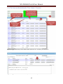
2. New paging and sorting method at the display of job instances.
Known bugs:
1. Generator output ports (and the ports which may be associated with more than one file as a
consequence of the effect of Generators) in embedded workflows may not be connected to the
output ports of the caller.
2. Conditional job call operations at certain graph positions may prohibit the call of a subsequent
collector job.
Release Notes to Version 3.1
Limitations of usage of the WS P-Grade Portal due to the temporary shortcomings of the current
implementation:
1. The numbers of job instances needed in the case of a Parameter Sweep workflow submission are
calculated in a static way during the preparation of the whole workflow submission. Dynamic PS
invocation is possible but in this case an upper estimation is needed for the number of PS runs.
Let’s assume that the upper estimation given by the user is N and the actual dynamic number of
runs is M where M<N. In this case gUSE generates N-M dummy jobs that are thrown away during
the execution.
19
WS-PGRADE Portal User Manual
2. If there is a collector job and any of its direct predecessor job instances has the state "init" then
the collector will not be executed and the associated workflow instance will not reach the state
"finished". It may be a bug because in the case of the "semi dynamic PS" (where M is less than N)
in N-M cases no output files will be forwarded to the subsequent job instances, and the state of
such job instances will be "no input" by definition. However the state of successors of "no_input"
job instances are set as "init" for the time being, so the information will be forwarded to the
collector that it needs not to wait for an input further which will never come. The solution will be
that the state "no_input" will be propagated to the collector which may run if all expected
genuine inputs has been produced. (Please note, that this limitation does not exist more since
Version 3.1b6)
3. A similar problem is that the programmed "no_input" cases (and job states) are not
distinguished from that when a job does not receives input due to missing configuration or due
to network error.
4. There are reported cases when the rescue operation after the suspending of a PS workflow does
not restart all needed job instances.
5. The implementation of Template definition is rather "unintelligent": Only the explicitly defined
features closeness can be reverted, but not all possible attributes of a job. Up to now the system
is not able to handle logical consequences among the closed-open state of attributes: For
example if the current submitter is gLite and the user opens the Type field in order to allow
other kind of submitters the sub features belonging to the other kind submitters cannot be
opened, so there is no way to configure them.
6. For the time being deleting of an Application does not includes the deletion of the eventual
instances of embedded workflows called from the given Application.
7. The graphic visualization (time space diagram of job instances) contains a bug in the parameter
sweep case: not all job instances are displayed the connection of them may be scrambled.
8. The input and the workflow configuration of a downloaded workflow instance does not
correspond to the output in all cases (See warning in 3.7.2.2.1)
9. Embedded workflows can be called from PS workflow with the temporary restriction that the
embedded workflows may not contain such a graph path where a generator object is not closed
by a collector, i.e. a single set of workflow instance inputs must produce a single set of outputs
and not an array of them. A generator object in this context may be a job with generator output
port or a caller job which returns more than one files at a given output port upon a single
embedded workflow instance invocation. If the user does not comply with this limitation the
result is not guaranteed. (See the typical use cases)
10. The number of input files may be forwarded to a job instance of a job having a Collector port is
restricted in 30. It is due to the limitation of the EGEE imposed on the number of files may be
collected in the input sandbox of a JDL file. As the storage size of the input sandbox is limited
anyhow the user is advised to use remote files if the number of input files of a collector port may
exceed the value 30.
20
WS-PGRADE Portal User Manual
I. Main Part
Introduction
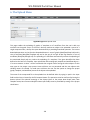
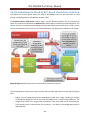
The WS-PGRADE Portal is a web based front end of the gUSE infrastructure. It supports development and
submission of distributed applications executed on the computational resources of the Grid and other
DCIs. The resources of the Grid are connected to the gUSE by a single point back end, the DCI Bridge.
According our vocation: "The Portal is within reach of anyone from anywhere"
The development and execution features have been separated and suited to the different expectations
of the following two user groups:
The common user (sometimes referenced as "end user") needs only a restricted manipulation
possibility. He/she wants to get the application "off the shelf", to trim it and submit it with
minimal effort.
The full power (developer) user wants to build and to tailor the application to be as comfortable
as possible for the common user. Reusability is important as well.
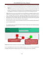
The recently introduced public Repository is the interface between the common and the developer user.
The developer user can put the ready to run applications in the Repository and the common user can get
the applications out from it.
The DAG workflow - based on the successful concept of the original P-Grade Portal - has been
substantially enlarged with the new features of the gUSE:
1. Job-wise parameterization gives a flexible and computing efficient way of parameter sweep (PS)
applications, permitting the submissions of different jobs in different numbers within the same
workflow.
2. The separation of Workflows and Workflows Instances permits easy tracking of what's going on
and archiving different submission histories of the same Workflow.
3. Moreover, Workflow Instances – objects created by submitting their workflow - make it easy to
call (even recursively) a workflow from a job of the same or of another workflow.
4. The data driven flow control of a workflow execution has been extended. The user can define
programmed, runtime investigation of file contents on job input ports.
5. The range of possible tasks enveloped in the unique jobs of the workflows has been widely
enlarged by the possibility to call workflows (discussed above) and by the ability to call remote
Web services as well.
6. Beyond the manual submission of a workflow, time scheduled and foreign system’s event
awaiting workflow execution can be set on the user interface of the WS Portal.
7. The back end infrastructure of the gUSE supports an extended usage: With the help of the DCIBridge the Administrator can reach new kind of resources, and the users (developers and
common users) may reach them the traditional way.
21
WS-PGRADE Portal User Manual
8. The WS-PGRADE Portal and the back end gUSE infrastructure is not a monolithic program
running on a single host but a lose collection of web services with reliable, tested interfaces. So
the system supports high level of distributed deployment and a high level of scalability (See
details in Chapter 5).
The target audience of the current manual is the developer user and the System Administrator (Chapter
5, 6, 7, and 10).
The structure of the first 3 chapters of the main part of the manual follows the basic development cycle
of a workflow:
In Chapter 1 the static skeleton of a workflow is discussed, describing the Graph and the
associated Graph Editor to produce it.
Chapter 2 describes the concept of Jobs and the rather complicated configuration of jobs.
In this chapter the parameter sweep related features, job configuration and tightly connected
job execution is discussed.
Chapter 3 discusses the Workflow related issues. It introduces the following terms:
The Workflow Instance (the running object created upon Workflow submission)
The Template, a collection of metadata, by means the reusability of a Workflow is
enhanced
The Application, a reliable, tested, self-containing collection of related Workflows
The Project, which is the intermediate state of an Application
The public Repository where the applications, which can be published, are stored
Beyond that, this chapter discusses workflow submission, observation and management
related features, strictly separating developer's and common user's methods.
Chapter 4 gives an overview of the portlet structure of the WS-PGRADE.
Chapter 5 defines the internal organization of the gUSE infrastructure.
Chapter 6 introduces the middleware technologies, used in the reachable computational
resources. This chapter describes the view mode of the DCI Bridge.
Chapter 7 defines the central user storage quota management
Chapter 8 deals with an independent look up system for SHIWA resources.
Chapter 9 describes the experimental implementation of WFI monitor by which one of the
central gUSE components, the workflow interpreter can be monitored.
Appendix I attached to the main part contains the user interface oriented "On-line Manual"
describing the unique menus.
Chapter 10 describes the Certificates menu.
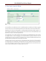
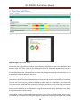
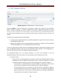
Chapter 11 introduces the usage statistics portlet that is represents the collection and
visualization of usage statistics in gUSE/WS-PGRADE is responsible for collecting and storing
metrics in the database and for display of these metrics.
Chapter 12 describes the whole steps of user management process: from user account creating
to password changing.
The basic terms and the connecting activities associated to them are summarized in Appendix II
22
WS-PGRADE Portal User Manual
The Appendix III is a case study i.e. it is a jump start for inpatient users.
The Appendix IV is a simple case study about the data driven call order of PS jobs.
The goal of the main part is to give a concept based description of the system. The Online Manual
(Appendix I) gives a keyhole view: the pages describe the local functionality of the given portlet or form.
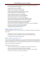
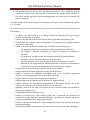
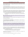
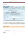
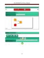
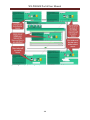
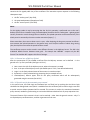
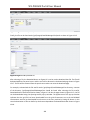
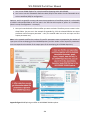
1. Graph
The Directed Acyclic Graph (DAG) is the static skeleton of a workflow. (See Appendix: Graph Menu)
The nodes of the graph, named jobs denote the activities, which envelop insulated computations. Each
job must have a Job Name. Job names are unique within a given workflow. The job computations
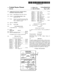
communicate with other jobs of the workflow through job owned input and output ports. An output port
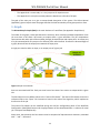
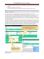
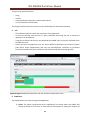
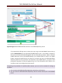
of a job connected with an input port of a different job is called channel. Channels are directed edges of
a graph, directed from the output ports towards the input ports.
A single port must be either an input, or an output port of a given job.
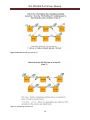
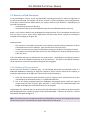
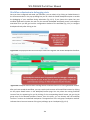
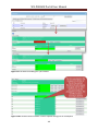
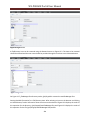
Figure 1 Graph of a workflow
Ports are associated with files. Each port must have a Port Name. Port names are unique within a given
Job.
The Port Names serve as default values to the "Internal File Names". The Internal File Names connect the
referenced files to the "Open" like instructions issued in the code of the algorithm, which implements
the function of the job.
The Internal File Names can be redefined during the Job Port Configuration phase of the Workflow
Configuration. (Workflow/Concrete tab->Configure button of the selected workflow -> selection of actual
job ->Job Inputs and Outputs tab)
Please note, that presently the Port Names must be composed of alphanumerical characters, extended
with "." and "-" characters.
23
WS-PGRADE Portal User Manual
There are immutable port numbers for the physical identification of ports. They are referenced as "Job
Relative Seq" within the Graph Editor. Input ports, which are not channels, i.e. no output port is
connected to them, are called genuine input ports. Output ports, which are not channels, i.e. no input
port is connected to them, are called genuine output ports.
1.1 The Acyclic Behavior of the Graph
The evaluation of a workflow follows the structure of the associated Graph: The Graph is acyclic, in order
to avoid reaching the starting job from any job, including the starting job itself. This acyclic behavior
determines the execution semantics of the workflow, to which the given Graph is associated to: The jobs,
which have no input dependencies can be executed subsequently, if all their input ports are "filled" with
correct values.
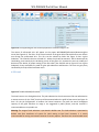
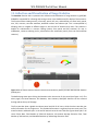
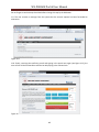
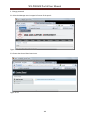
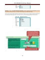
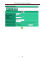
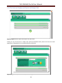
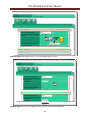
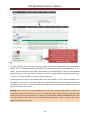
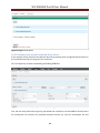
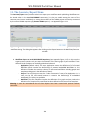
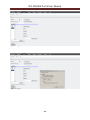
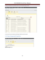
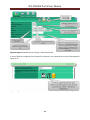
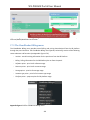
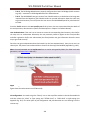
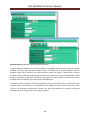
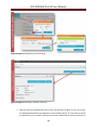
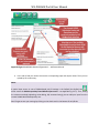
1.2 The Graph Editor
Graphs can be created with the interactive, graphic Graph Editor. The Graph Editor can be reached in the
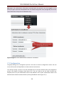
tab Workflow/Graph.
Pressing the Graph Editor button: a new instance of the Graph Editor can be downloaded from the server
of the WS-PGRADE Portal. (See Appendix Figure 2 - Graph Editor) An alternative way to start the Graph
Editor is pressing the button Edit, associated to each element of the list, showing the existing user's
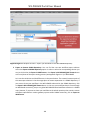
Graphs. The editor runs as an independent Webstart application on the user's client machine.
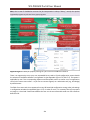
With the Graph Editor the user can create, modify and save a graph in an animated, graphic way. The
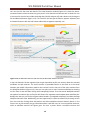
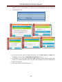
Editor can be handled by the menu items or by the pop up menu commands, appearing after a right click
on the graphic icons of jobs, ports or edges (channels). (See Appendix Figure 2 Graph Editor) The taskbar
containing the icons "Job", "Port" and "Delete" gives an alternative to create jobs, ports (of a selected
job) or to delete a selected job, a port, or a channel.
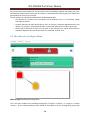
With the slider, the user can zoom in/out the image of the created workflow. The recently touched
object (created or identified by left click) becomes "selected". The selected state is distinguished by a red
frame around the icon's graphic image. A special - third - editing mode is required for the creation of
edges (channels).
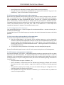
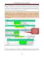
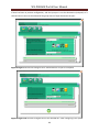
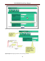
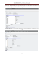
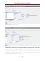
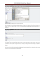
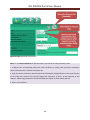
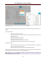
1.2.1 Menu items
24
WS-PGRADE Portal User Manual
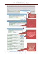
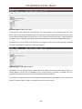
1.2.2 Popup menu items
The popup menu appeared after click on right mouse button.
25
WS-PGRADE Portal User Manual
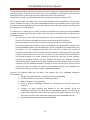
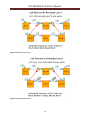
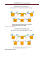
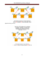
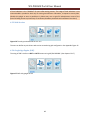
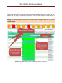
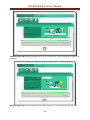
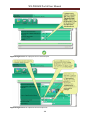
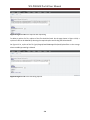
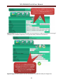
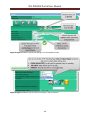
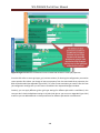
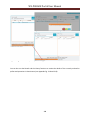
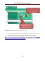
1.2.3 Creation of channels
It is executed in three steps:
1. Pressing the left mouse button over a port icon.
2. Dragging the pressed mouse to a different port icon of a different job.
3. Releasing the mouse button.
Note: The syntax rules are controlled: input port can be associated only to an output port, no destination
(input port) of a channel can be shared with different channels, the acyclic property of the graph must be
preserved.
2. Jobs
Introduction
The workflow is a configured graph of jobs i.e. it is an extension of the graph with attributes, where the
configuration is grouped by Jobs.
This chapter discusses the properties and configuration of jobs. The properties of jobs reflect the
elaboration of the enclosing workflow. However the properties of the workflows as a single entity are
discussed in Chapter 3. The Job configuration includes:
26
WS-PGRADE Portal User Manual
algorithm configuration,
resource configuration and
port configuration.
The algorithm configuration determines the functionality of the job, the resource configuration
determines where this activity will be executed, and the port configuration determines what the input
data of the activity are and how the result(s) will be forwarded to the user or to other jobs as inputs. A
job may be executed if there is a proper data (or dataset in case of a collector port) at each of its input
ports and there is no prohibiting programmed condition excluding the execution of the job. If datasets
(more than one data items – where data item is generally a single file) arrive to the input(s) of a job they
may trigger the multiplied execution of the job. Exact rules of such – so called parameter sweep (PS) - job
invocations will be discussed in chapter 2.3.2.4. At each job execution a runtime environment will be
created. It includes the input data triggering the job execution, the state variables and the created
outputs. The name of this runtime environment is the job instance object. During the execution of a
single workflow one job instance will be created for each non PS job. The N-fold invocation of a PS job
creates N job instances.
The collection of job instances created from the jobs belonging to the workflow during a single workflow
submission is called workflow instance.
Note: In case of embedded workflow call the execution of the job which calls the embedded workflow
creates a new workflow instance of the called workflow.
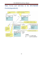
2.1 Algorithm
An algorithm of a job may be:
1. a binary program,
2. a call of a Web Service (a distinguished form is the calling services by REST – see chapter 18.) or
3. an invocation of an embedded Workflow.
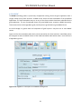
The configuration (See Appendix_Figure_13) of the algorithm can be selected by any of the tabs of the
group Job execution model on the job property window (tab Workflow/Concrete -> button Configure of
the selected workflow -> selection of actual job -> tab Job Executable).
2.1.1 Binary Algorithm
In case of a binary program - selected as "Interpretation of Job as Binary" on Appendix Figure 13 - the
algorithm
can be coded in a local file to be delivered to an - eventually remote - resource (with some local
input files) and executed there (see 2.1.1.1),
can be a legacy (SHIWA) code (the Submittable Execution Node - SEN): already waiting for input
parameters to be executed on a dedicated remote resource (2.1.1.2).
More details in chapter 23 within Menu-Oriented Online Help
can be a BOINC Desktop grid related algorithm, where the user may select one of the prepared
executables stored on the "middle tier" (the BOINC Server) of the execution sequence. In this
27
WS-PGRADE Portal User Manual
case the job will be executed on one of the client machines (on the "third tier") of the BOINC
Desktop Grid.
can be similar to the previous option: the user may select a valid executable stored in an
application repository (EDGI AR). In this case the job will be executed on one of the client
machines (on the "third tier") of the BOINC Desktop Grid as well. (chapter 16). Additionally, the
place of executing the selected code can be a cloud infrastructure (CloudBroker: chapter 17).
Note: in case of UNICORE-based job configuration the user can select from two options: the user can use
preloaded executable from a tool list or he/she can upload binary code by local browser. (See
Appendix_Figure_13, Part F)
2.1.1.1 Travelling binary code
In this case translated binary code is delivered to the destination place (defined by the resource
configuration), together with the eventual existing local input files.
The executable binary code references the input and output files in the arguments of its "open" like
instructions. These references must be simple file names relative to the working directory of the
destination where the executables runs.
The same relative file names must be defined as Internal FileName(s) during the port configuration of the
respecting job. (Workflow/Concrete tab -> Configure button of the selected workflow -> selection of
actual job -> Job Inputs and Outputs tab).
The kind of the source code can be:
Sequential
Java
MPI
2.1.1.1.1 Sequential
This kind of code may be compiled from C, C++, FORTRAN, or similar source, may be a script (bash, Csh,
PERL, etc.) or may be a special tar ball corresponding the name convention <any>.app.tgz. This later case
will be dissed in the Tar ball as executable paragraph.
Generally, it requests no special runtime environment.
In the contrary case the runtime code
either must be present on the requested resource or
delivered together with the executable as input file of the job or
needs to be mentioned - in case of gLite resources - in the Requirements part of JDL/RSL
2.1.1.1.1.1 Tar ball as executable
The file <any>.app.tgz will be delivered to the destination resource. Subsequently the tar ball will be
expanded, and the stage script expects a runnable file named as <any> in the root of the local working
directory, which can be started.
28
WS-PGRADE Portal User Manual
Let’s assume that the original binary program "intArithmetic.exe" expects two text files "INPUT1" and
"INPUT2" to execute a basic arithmetic operation, whose result will be stored in the text file "OUTPUT",
where the kind of operation is define by a command line argument: for example "M" for multiplication.
We intend to create such a job which receives just one argument (through a single input port which
saves the value in file "INPUT1") and this will be multiplied by 2.
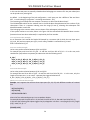
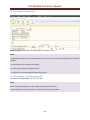
The following shell script will be crated and named as test.sh: #!/bin/sh
echo "2" > INPUT2
chmod 777 intArithmetic.exe
./intArithmetic.exe M - This file must be packed together with intArithmetic.exe and must be named as
test.sh.app.tgz. The importance of the tar ball feature is that the complex run time environment of the
runnable code can be transferred to the remote site as one entity if it is useful and applicable, and the
user need not bother to associate a separate input port to each needed input file.
2.1.1.1.2 Java
The binary code must be a .class or .jar file. The associated JVM is stored in a configuration file, which
can be set only by the System Administrator. The JVM is resource type dependent, therefore it is stored
as part of the Submitter (2.2.1).
After job submission Java class (or JAR) code and code of the Submitter dependent JVM is copied
automatically to the destination as well.
2.1.1.1.3 MPI
The binary code must be the compilation of a proper MPI compiler. It is assumed that a corresponding
MPI Interpreter is available on the requested destination. As the program may spread on several
processors (maximum number of needed processors) must be defined.
If a broker is selected instead of a dedicated site, the automatically generated JDL/RSL entry assures that
only a proper site is selected as destination, where the MPI dependent requirements are met (see 2.2.3).
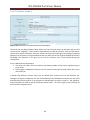
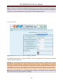
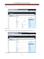
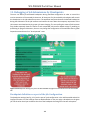
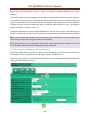
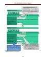
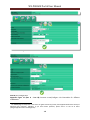
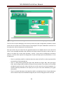
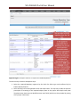
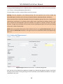
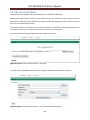
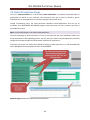
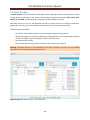
2.1.1.1.4 Configuration
The configuration can be done after selecting the Interpretation of Job as Binary tab as Job execution
model on the job property window (Workflow/Concrete tab -> Configure button of the selected
workflow -> selection the icon of the actual job -> tab Job Executable). See the result on the Appendix
Figure 13.
The choices of the radio button Kind of binary selects the type of the binary code among the set
members Sequential, Java, MPI. The field MPI Node Number must be defined only in case of running MPI
code (see 2.1.1.1.3). The field Executable code of binary identifies the code, which must be uploaded
from the local environment of the client (by the Local option) to the Portal, with the help of the file
browser button Browse. However, you can choose the Remote option if your executable binary is not on
your local machine. In this case you need to add properly the URL of executable (about the supported
remote protocols see chapter 14: Defining Remote Executable and Input).
29
WS-PGRADE Portal User Manual
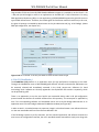
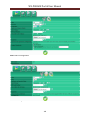
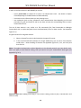
The field Parameter may contain eventual command line parameters expected by the binary code. This
parameter will be transferred to the destination site of job execution together with the code of
executable. The configuration must be fixed in two subsequent steps:
1. In the current page pressing the button Save.. confirms the settings. However, the settings are
saved only on the client's machine at this stage.
2. To synchronize the client's settings with the server's settings the user has to use the button Save
on Server. (tab Workflow/Concrete tab-> button Configure of the selected workflow) See
Appendix Figure 12.
2.1.1.2 SHIWA code
More details in chapter 23 within Menu-Oriented Online Help.
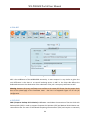
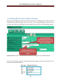
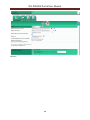
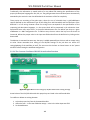
2.1.2 Web Service (WS) call
In the case when the tab Interpretation of Job as Service of the group Job execution model will be
selected the job duty is to call an existing remote Web Service.
It has three parameters:
Type: Reserved for later use. At present the single selectable value is "web service"
Service: Defines the URL where this service is available
Method: Defines a web service method. This method should be defined on the remote machine
defined as "Service"
A distinguished form of service call is the REST-base service call (see chapter 18.)
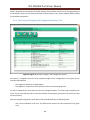
2.1.2.1 Parameter passing
Each service method can have some inputs and one output parameter. They must match the Input and
Output ports of the current Job.
In the description of the WDSL file the tag "parameterOrder" enumerates the input parameter names of
the given method. The external association is based on the enumeration of the input port numbers in an
increasing order.
Example: let's suppose, that the given job has the input port set containing port numbers {2,7} and
"parameterOrder" has the value param_one param_two. In that case port 2 is associated to
"param_one" and port 7 is associated to "param_two".
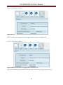
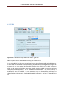
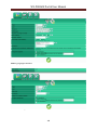
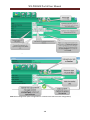
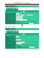
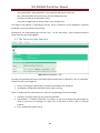
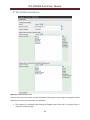
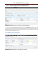
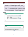
2.1.2.2 Configuration
The configuration can be done after setting Interpretation of Job as Service on the job property window
(Workflow/Concrete tab -> Configure button of the selected workflow -> selection of actual job -> tab Job
Executable). See Appendix Figure 15.
By setting the Replicate settings in all Jobs check box the current WS job configuration is copied in all
Jobs of the Workflow. All settings on the given page must be confirmed by the Save button.
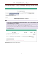
2.1.3 Embedded Workflows
Embedded workflows are full-fledged workflows; their instances can be submitted under the control of a
different workflow instance.
30
WS-PGRADE Portal User Manual
The workflow embedding implements the subroutine call paradigm: Any workflow with its genuine input
(not participating in channels) and all output ports can be regarded as a subroutine with its input and
output parameters. A special type of job can represent the caller of the subroutine.
The parameter passing is therefore represented by copying (redirecting) the respective files.
Not all genuine input and output ports of the called workflow must participated in the parameter
passing. However, the input of the called (embedded) workflow must be definite. Either a (file) value
must be associated to a genuine input port, or the input port of the caller job should be connected to the
genuine input port of the called job.
In a similar way, an output port of a caller job must be connected to an output port of the embedded
workflow. The remote grid files, direct values, SQL result sets are excluded from the subroutine call
parameter transfer:
The input ports of the caller job forwarding the "actual parameters" may be associated to
channels of local files or uploaded local files but not to remote grid file references.
Similarly the output ports of caller jobs may by just local files but not remote grid files.
The eventual original file associations of ports participating in the parameter file transfer in the
called (embedded) workflow ("formal parameters") will be overruled by the configuration of the
connection i.e. by the configuration the caller job of the caller workflow. The concept of
workflow instance makes recursion feasible and the possibility of conditional run time port value
evaluation ensures that the recursive call is not infinite. As it was mentioned in the introduction,
the workflow instance is an object containing the whole run time state of that workflow,
extending the workflow definition by state variables and output files. Workflow instances
represent the dynamic memory (stack or hype) needed for recursive subroutine calls. This object
is created upon each workflow submission. To enforce a kind of security policy, (similarly to the
checking the type and number of actual formal parameter passing), only workflows with
Template restriction can be used as callable (embedded) workflows.
Summary: The following steps must be done in the simplest case of an embedded application
development cycle:
1. Configure the workflow which is intended to be used as embedded.
2. Test the workflow execution for the needed input values.
3. Make a Template from the workflow
4. Create a genuine embeddable workflow by referencing the Template. (Create by
Template)
5. Configure the caller workflow (See detailed in the next chapter). During the
configuration, define the name of the genuine embeddable workflow in the caller job. As
a part of the configuration of the caller job associate all the input and output port of the
caller job to a proper input (respectively output) ports of the embedded workflow.
6. Test the application by submitting the caller workflow
31
WS-PGRADE Portal User Manual
2.1.3.1 Configuration of calling of Embedded Workflows
2.1.3.1.1 Selection of the called workflow
The needed specialized type of job in the caller workflow is distinguished by the tab Interpretation of job
as Workflow of the group Job execution model on the Job Configuration page (tab Workflow/Concrete ->
Configure button of the selected workflow -> selection of caller job -> Job Executable tab). As the
semantic of the embedded workflow is hidden, the only possibility here to select an existing workflow
from the list box, which has the "for embedding select a workflow created from a Template label. See
Appendix Figure 16
2.1.3.1.2 Parameter passing
The parameter passing is defined from the "viewpoint" of the caller job, i.e. it is defined on the port
configuration page of the caller. (Workflow/Concrete tab -> Configure button of the selected workflow ->
selection of caller job -> Inputs and Outputs tab)
For each port definition, the yes value for the port´s Connect radio button {input|output} port to the
Job/{input|output} port of the embedded WF: can be selected.
From the appearing list box Job/{input|output} the proper port of the embedded (called) workflow can
be selected.
The list elements can be identified by the string containing the job name and port name, separated by a
"/" character. Both names refer to the Graph of the embedded workflow.
Example: See the Appendix Figure 21 for the tab Inputs and Output and the Appendix Figure 22 for
detailed explanation.
2.1.3.1.3 Use cases of workflow embedding
32
WS-PGRADE Portal User Manual
Figure 2 Embedding workflow I.
Figure 3 Embedding workflow II.
33
WS-PGRADE Portal User Manual
Figure 4 Embedding workflow III.
Figure 5 Embedding workflow IV.
34
WS-PGRADE Portal User Manual
Figure 6 Embedding workflow V.
35
WS-PGRADE Portal User Manual
Figure 7a and 7b Embedding workflow VI.
Figure 7c Embedding workflow VII.
36
WS-PGRADE Portal User Manual
2.2 Resource of Job Execution
In our terminology a resource can be any identifiable computing environment, where the algorithm of
the job can be executed. For example: a local host, a cluster, a cluster belonging to a Virtual Organization
of any Grid, a whole Grid with hidden details, etc. A given resource of job execution - depending on job
type and circumstances
can be defined by the user directly or
can be determined by the Grid middleware upon the user defined properties of the job.
Broker: In this case the decision may be delegated to the gLite broker. This is the habitual case when the
user has access to just a certain Virtual Organization and the broker selects a proper site among the
available sites belonging to the given VO.
Important notes:
The resources in the gUSE environment are set mainly by special property parameters of those
Components which are of "submitter" type. (See the Internal services menu).
In cases of certain resource types final parameter setting must be done in the Resources menu.
In the special case of the PBS resource the user must complete the resource definition using the
Public key menu.
If the executable code must be delivered to the resource then – depending on the algorithm and the
expectation, about the needed environment of the job execution – the place of the optimal execution
can be selected in a hierarchic way defined along the next paragraphs.
2.2.1 Submitter (DCI) type selection
On the top of the hierarchy a submitter type can be selected, where the term submitter refers to a
dedicated middleware technology of target DCI, applied to find a resource which has the capacity to
match the requirements of the algorithm. There are two kinds of submitters:
1. Local: this means that the system executes the job on a special “local” infrastructure set up and
maintained by the local Administrator. It is a dedicated submitter.
2. One of the widely accepted third party middleware technologies which enable the usage of
remote resources {GT2, GT4, GT5, gLite, PBS, GAE ..}. Each of them has a dedicated plug in DCI
Bridge. DCI Bridge is the unified back end service of the gUSE.
Configuration: the submitter type can be selected by the radio button Type of the job property window
(tab Workflow/Concrete -> button Configure of the selected workflow -> selection of caller job -> tab Job
Executable). See Appendix Figure 13.
Note: The actual values can be viewed and selected are dependent on the current settings of the Internal
services menu, which is controlled by the System Administrator of the portal.
37
WS-PGRADE Portal User Manual
2.2.2 VO (Grid) selection
In the one but highest level of resource definition hierarchy a Grid or Virtual Organization (VO) can be
selected which supports the selected middleware technology in 2.2.1.
Note: the terms “VO” “Grid” are used with different meanings within the realm of different technologies,
and here we use them in a bit sloppy way to indicate the hierarchically highest group of separately
administered resources using a common technology.
The proper tabs of the Resources menu enumerate the names of administrative domains (Grids/VO-s)
using proper submitter (middleware) technology. It is the privilege of the System Administrator to
maintain these tables. See the check boxes belonging to the label Grid: on Appendix Figure 13.
2.2.3 Site selection
The site selection may define the place of actual execution of the given job - within the selected
administrative domain named VO or Grid (see 2.2.2)
This - third level - selection appears only in the case of certain middleware (GT2, GT4, GT5, PBS, GAE).
Note: In the case of the gLite middleware technology it is assumed that the meta site broker redirects
the given job to a proper site suggested by the information system.
To assist the decision of the broker, additional information can be added to the job selected by the
JDL/RSL editor. (Choose Workflow/Concrete tab -> Configure of the selected workflow button ->
selection of actual job -> JDL/RSL tab).
Configuration: The site can be selected by the list box Resource: of the job property window. See
the part B of Appendix Figure 13. Please note that if the Type is SHIWA then the site and Job
manager selection is used in a somewhat different context (More details in chapter 23 within
Menu-Oriented Online Help).
2.2.4 Job manager selection
The job manager selection is possible only if the the submitter type (see 2.2.1) is GT2, GT4 or GT5. In the
lowest level of the resource definition hierarchy a local submitter (popularly called "job-manager") – in
the praxis the name one of a priority queues - can be added to the defined site.
The named priority queues belong to the local scheduler of the cluster which executes the job, where
the queues differ from each other in job priority classes. Jobs with high priority are scheduled faster, but
their execution time is rather limited, while long jobs will be purged from the system after a longer
elapsed wall clock time interval than the high priority ones, but they must run in the background. The
information about the local submitters is part of the site definition.
If a site supports more than one job manager than the site must be defined with multiple job manager
types in the resource list of the given VO (or Grid). Example: Let us insert (being System Administrator) by using the New button - the following items on the tab Settings/Resources/gt2 of the selected VO:
(URL= "silyon01.cc.metu.edu.tr", Job Manager ="jobmanager-lcgpbs-seegrid")
(URL= "silyon01.cc.metu.edu.tr", Job Manager ="jobmanager-fork")
38
WS-PGRADE Portal User Manual
(URL= "silyon01.cc.metu.edu.tr", Job Manager ="jobmanager-lcgpbs-seegrid-long")
Configuration: The local submitter of a dedicated site can be selected by the list box Job Manager of the
job property window. See the lower part of Appendix Figure 13.For example id the if the selected
argument of the list box Resource is silyon01.cc.metu.edu.tr then each of the 3 Job Managers defined in
the example above (jobmanager-lcgpbs-seegrid, jobmanager-fork, jobmanager-lcgpbs-seegrid-long) can
be selected.
2.3 Port Configuration
Ports associate the inputs and outputs of the insulated activities, hidden by the job with the
environment.
2.3.1 Job model dependent access of port values
Values are associated to each input and output ports.
The way these values are connected is different, according to the job model.
2.3.1.1 Case of binary common travelling code
If these values are read/written by binary programs, supplied by the user (See 2.1.1), then the input field
Internal file name defines the string, which must be equal with the name of file, which will be opened
within the binary program during the run.
This convention makes the transfer of the named values possible. The field Internal file name is
configurable on the I/O tab. (Workflow/Concrete -> button Configure of the selected workflow ->
selection of actual job -> tab Job Inputs and Outputs, see Appendix Figure 16)
Also see Appendix Figure 17 and Appendix Figure 18Shortly speaking, the arguments of the file open like
instructions, within the executable, must be associated to the names of local files in the working
directory of the resource host, where the executable runs.
In the input case, the values coming from the port are copied here.
In the output case, the file, which has the proper Internal file name, is used to forward the values
to the output port.
2.3.1.2 Case of binary SHIWA code
More details in chapter 23 within Menu-Oriented Online Help
2.3.1.3 Case of Web Service code
The question of port value passing is discussed in 2.1.2.2.
See Appendix Figure 20 and chapter 2.1.2.
2.3.1.4 Case of Embedded Workflows
The association of ports (caller job to, ports of the workflow) is discussed in 2.1.3.1.2
See Appendix Figure 21 and 22 and chapter 2.1.3 for details.
2.3.2 Input ports
About configuration see Appendix: Figure 17. This chapter deals with the following topics:
Availability of data to a single port (Port condition 2.3.2.1, Collector port 2.3.2.2 )
Source of data to a single port (Origin 2.3.2.3)
Effect of data sets received on multiple input ports on the execution of the job ( 2.3.2.4)
39
WS-PGRADE Portal User Manual
Values to an input port
may be directly defined values;
can come from an external source;
or they can be a file, produced by a foreign job through its own output port.
If each value has arrived on each input ports of a job, then the job can be executed. Two special
circumstances may prohibit or postpone the execution of a job:
1. If there is a condition connected to an input port of a job or
2. If it is a collector port
2.3.2.1 Port condition
Pitfall: Port condition defined in the configuration phase to an input port may prohibit the execution of
the associated binary or webserver job. (See the restriction notice at 2.6.3.3.1) Optionally, a user can put
a condition on the value, delivered by the port.
The run time evaluation of this condition yields a Boolean value. If this value is false, then the workflow
interpreter omits the execution of the job and executions of its consequence jobs from the executions.
The state of the job will be "Term_is_false", when the run time evaluation of the input port condition
yields the value false, and the states of eventual successor jobs remain "init". The evaluation of port
condition does not influence directly the overall qualification of the state of the workflow: The applied
condition is regarded to be a programmed "branch" and the state of the workflow can be "Finished",
even if there are jobs remained in "init" and in "Term_is_false" states.
2.3.2.1.1 Port condition configuration
See Workflow/Concrete tab -> button Configure of the selected workflow -> selection of actual job -> tab
Job Inputs and Outputs. The choice of value View of the radio button Port dependent condition to let the
Job run: allows the editing of port dependent conditions, to permit/exclude running of the job. In the
appearing interface the details of a two argument Boolean operation must be defined:
The first argument is fixed. It is the value to be delivered by the current port to the job.
The comparing second argument is selectable by the {Value: | File:} radio button allowing to
choose the definition of direct comparing Value, or a value of a File received via a different input
port.
In the first case the user defines the direct value in the input field Value:, in the second case list
box File: enumerates the port names to select from.
The kind of the Boolean operation must be defined by the list box operation, where one of the
set== (equal);
!= (not equal);
contain. (The first argument contains the second argument if both arguments are regarded as character
strings and the second argument is a true substring of the first) can be selected.
Example: The job Job0 may run if the value of the file connected to the port PORT0 has the substring
value connected to PORT2. See Appendix Figure 23
40
WS-PGRADE Portal User Manual
2.3.2.2 Collector port
In the base case of Parameter Sweep workflow execution a job within the static context of its workflow
(not considering the eventual embedded, recursive cases) receives more than one input files through a
given port.
In this case, according to the general rules of port grouping (See dot and cross products at 2.6.1.2.2),
each new file participates in a different, new job submission. In the simplest case when a job has just one
input port and two files are sent to this port then two job executions (and two job instance creations)
will be triggered, one for each file arrival.
However, in case of a Collector Port the job call is postponed, until the latest file is received on this port,
and a single job execution elaborates all input files. Because of the special nature of Collector Port there
are some restrictions
on the places where these ports may occur;
on the name of files they are associated with:
Port occurrence restriction: Because of the nature of collector ports, they can’t be genuine input ports
which referencing single files. (We call an input port to be genuine input port if it is not the destination of
a channel.)
A consequence is that they mustn't be applied in a job encapsulating Web Service, SHIWA or Embedded
Workflow call. Restriction on the names of associated files:
File names must have a fixed syntax i.e. they must contain an index postfix separated from the
prefix by an underline character ("_").
The index must be encountered staring from zero ("0").
The prefix must match the Input Port's Internal File Name (See 2.1.1.1).
Warning: The usage of the collector ports requires a collaboration of the user defined binary code of the
job. It is the responsibility of the user code to find, encounter, and read all the input files whose names
match the definition above.
Jobs having the code able to meet these requirements are called as Collector jobs.
2.3.2.2.1 Collector port configuration
See Workflow/Concrete tab -> Configure tab of the selected workflow -> selection of actual job -> Job
Inputs and Outputs tab. The collector property of an input port can be configured if the radio button is
set to View. The choice of value All of the radio button Waiting configures a port to be a Collector Port.
Example: See Appendix Figure 24.
2.3.2.3 Origin of values associated to an input port
Input ports either can be destination of channels (similar functions have the input ports of embedded
workflows, associated to an input port of the calling job) where the received values are defined
elsewhere, or the data may be defined at the input port definition (Genuine input port).
2.3.2.3.1 Genuine input ports
Five basic cases are distinguished, each subdivided according to whether a single or a set of files are
defined. This latter case is used to drive a sequence of calculations, called Parameter Sweep (PS).
Common, PS related properties of genuine and channel import ports are discussed in 2.3.2.4
41
WS-PGRADE Portal User Manual
Basic sources
Basic data sources of genuine input ports can be:
Local file
Remote file
Direct value
Online value generation from Database
Application dependent set of parameters
PS Input Ports: A job may receive more than just one data items via a genuine input port. (See Local,
Remote and Database cases). In this cases little integer indices – which are consecutive numbers starting
from zero - will be associated to the encountered data items.
But not this but an explicit user defined number (called Input Numbers) associated to the given port
determines whether the port will be regarded as a parameter sweep (PS) input port. The default value of
Input Numbers is 1 and it means a common Input Port.
If the user redefines it as N > 1, then port becomes a PS Input Port. The number N may differ from the
number of existing data items (M). If N < M then the data items encountered by higher indices than (N-1)
will be discarded.
If N > M > 0 then additional user defined setting (called Exception at exhausted input ) defines what
happens if the set of data items of the Basic source is exhausted: Use First means that the data item with
index 0 will be reused for all missing indices i where M <= i < N
Use Last means that the data item with index M-1 will be reused for all missing indices i where M <= i < N
Abort means that the job will be aborted and its status will be set as failed. The configuration is shown in
the local case on Appendix Figure 25.
Local file
A local file on the client machine is uploaded to the server of the portal, during the configuration phase.
Upon job submission the value of this file is forwarded to the resource, where it's elaborated.
Local file configuration
See Workflow/Concrete tab -> Configure button of the selected workflow -> selection of actual job -> Job
Inputs and Outputs tab. The value Upload of the radio button indicating the data source must be
selected and subsequently, a local file must be selected by the browser button Browse.. Example: See on
Appendix Figure 17 and on Appendix Figure 18 the configuration window before and after the definition
of the file to be uploaded. Important note: The appearance of the selected file name in the input field of
Upload in itself is not guarantee of the successful upload: As it was emphasized in 2.1.1.1.4 the
configuration must be confirmed by the button Save on Server on the workflow configuration window
(See Appendix Figure 12)
Special case: In case of REST-type configuration (in channel-type input port at Stream as HTTP sending
type) the file handling is similar to local file handling (see chapter 18).
Local file configuration in parameter sweep case
In this special case, the name and the content of the file are restricted: The name must be
"paramInputs.zip" and the content must be a compressed zip file of children files, named as subsequent
42
WS-PGRADE Portal User Manual
integers, starting from 0: "0", "1", "2". It is also the responsibility of the user, that contents of the
children files are digestible for the job.
See general comments about PS Input ports .Example: See Appendix Figure 25. Notice even if the file
"paramInputs.zip" contains 10 elements only the first five (indices 0, 1, 2, 3, 4) will be considered.
Remote file
A remote file will not be copied in configuration time, only its way of access is remembered.
The remote storage is visited during job submission time and the proper file content is copied to the
destination, where the content is accessible to the job. The URL implementing the access of the remote
file is technology dependent:
It can be LFC Grid file catalogue entry if the Type of the job (See 2.2.1) is gLite or it can be a low
level (Globus compatible) one, prefixed with a gsiftp protocol. The use of the LFC catalogue does
not generate additional duties for the user:
The proper Environment variables are maintained by the System Administrator in the proper
Submitter Configuration File.
(The Environment variables are needed to assist the system generated scripts to fetch the
content of the remote files and put them as local files to the resource, where job is running.)
Note: The WS-PGRADE portal has a special portlet to handle those remote files which use the LFC
catalogue technology. (See the LFC menu)
This portlet is independent from the workflow submission system and supports the user to
control the whole life cycle of remote files.
Remote file configuration
See Workflow/Concrete tab -> Configure button of the selected workflow -> selection of actual job -> Job
I/O tab. The value Remote of the radio button indicating the data source must be selected and the
associated input field must be filled with the required URL.
Warning: At present, independently of the setting of the check box Copy to WN the remote file will be
copied to the resource, where the job will run.
The supported protocol list to remote input resource definition is available in the chapter 14.
Remote file configuration in Parameter Sweep case
To get a parameter sweep case the port must be defined as a PS Input Port i.e. Input Numbers must be
greater than one.
In this case the user defined URL defined in the input field associated to the radio button selector
Remote refers only to the prefix of the paths of files to be accessed. The names of the existing remote
files must have an additional postfix, consisting of an underline separator character ("_") and a string of
indices starting from 0. It is also the responsibility of the user, that the contents of the remote files are
digestible for the job.
Example: The URL lfn:/grid/gilda/a/b may refer to the existing grid files
lfn:/grid/gilda/a/b_0;
lfn:/grid/gilda/a/b_1;
lfn:/grid/gilda/a/b_2;
43
WS-PGRADE Portal User Manual
Direct value
In this case, not a file, but a user defined string is forwarded to the job through the port. Differing from
the other methods of input definitions, it is not possible in this case to define different contents for
subsequent job submissions, if the port is used as PS Input Port. Each PS generation of this port
generates a set containing identical files.
Direct value configuration
(See tab Workflow/Concrete -> button Configure of the selected workflow -> selection of actual job ->
tab Job Inputs and Outputs).
The content of the input field activated by the selection of Value of the radio button indicating the data
source will be delivered as a file to the working directory of the node, executing the job. The name of the
file is a user defined one; identical with the input field of Input port’s Internal File name.
Online value generation from Database.
The values are generated online (in job submission time) by an SQL Select statement.
Only values are taken from the result set, which belong to the left column listed in the SQL Select
statement.
If it has not been defined by the "ORDER BY" clause, the order of elements in the result set is haphazard.
In case of simple file generation the first element of the result set is selected to be the content of the
input file. At present, only the Unix mysql implementation of SQL is supported.
Database source value configuration
(See tab Workflow/Concrete -> button Configure of the selected workflow -> selection of actual job ->
tab Job Inputs and Outputs)
The configuration must be defined in 4 subsequent input steps.
These steps belong to input fields which are hidden until the user selects the choice SQL of the radio
button indicating the data source. Example: See Appendix Figure 26.
Database Source
The URL of the database must be defined in the following form:
<LanguageEmbddingProtocol>: <ImplementationProtocol>:// <Host_url> /<path>
Pitfall: At present, only the protocol jdbc:mysql: is handled. The input field is labeled as SQL URL (JDBC).
Database Owner
The owner of the file representing the database must be defined.
The input field is labeled as USER.
Database Security
The password known by the owner of the file representing the database must be defined.
The input field is labeled as Password.
Database Query
The argument of the SQL Select statement must be defined.
The input field is labeled as SQL Query SELECT.
44
WS-PGRADE Portal User Manual
Database source value configuration in Parameter Sweep case
From each value of the result set (belonging to the left column of Select statement) a different file will be
composed. Example: Appendix Figure 26 discusses the case when the SQL Select statement produces
four records but the port is configured as PS Input Port which will receive 10 files.
Application Dependent Parameter Association to a port
It is a special tool to associate input parameters to a distinguished application, which will be prepared by
a special –application dependent - submitter, ready to forward these parameters. The tool can be
selected by the value "Application specific properties" of the radio button determining the kind of the
input. (See Appendix Figure 19)
The button view property window opens a form containing the editable table of required inputs.
Notes: The following additional conditions are needed to use this input definition facility:
The portal administrator makes this option selectable for the user, when the administrator configures
the job <Jobname> by a special way; by putting the file <Jobname>.jsp in the subdirectory named
"props", located in a proper place of the Tomcat server.
The file <Jobname>.jsp contains the form needed to read the given application specific input parameters,
which are forwarded as additional values to the application sensitive submitter of the job.
Shortly speaking, by plugging in the file <Jobname>.jsp in the system the control of input definition is
passed to the user. It is assumed that the special keys defined in the <Jobname>.jsp to identify the
parameter, are recognized properly by the special destination submitter of the job.
2.3.2.4 Effect of data sets received on multiple input ports on the execution of the job
A genuine input port may deliver for subsequent job executions more than one files, if the a proper
number value is set. This value, called Input Numbers must be defined during the configuration of the
job. Its default value is 1 meaning no parameter sweep case. Rules for Input Numbers was discussed in
chapter 2.3.2.3.1.1 in the section PS Input PortsIn case of a channel input port, the possibility to set the
value of "Input Numbers" mentioned at the genuine input ports is missing, because this number will be
computed, and it indicates the overall number of files which must be created on the output of the given
channel as a result of the full execution of the workflow. The proper setting of a special additional key
(Dot and Cross PID) can connect an input port with other input ports of the same job from the point of
view of the parameter sweep controlled job elaboration. See more detailed in 2.6.
2.3.3 Output ports
Output ports describe
the source,
destination, and
lifetime
of data produced by the jobs. Depending on the kind of the job execution model, which may be a binary
executable, a service call or the submission of an embedded workflow, the result can be retrieved in a
different way.
Note: Special kind of output ports are the Generator output ports, where upon the execution of a single
job instance more than one file may appear and will be forwarded. (See Appendix Figure 27)
45
WS-PGRADE Portal User Manual
2.3.3.1 Source of output data belonging to the port
2.3.3.1.1 Case of Binary Executable
In case of binary executable code, the source of data is associated to the file whose name is configured
by the user in the input field Output Port’s Internal File Name. See Appendix Figure 27 (tab
Workflow/Concrete -> button Configure of the selected workflow -> selection of actual job -> tab Job
Inputs and Outputs).
According to the convention made with the author of the binary executable code the user defined string
associated with Output Port’s Internal File Name must stand in the argument of the "Open" like
instructions of the Binary executable to determine the location of the generated output file relative to
the working directory, on the worker node of the job execution. The same string is used, to define a
unique sub library, if the content of the file must be copied to the Portal server as destination.
2.3.3.1.2 Case of Service Call
In case of Service Call the proper physical port number identifies the source similar to the case of input
ports (see 2.1.2.2)
2.3.3.1.3 Case of embedded Workflow
In case of embedded workflow call, the user must manually select among the possible output ports of
the embedded workflow to identify the source.
2.3.3.1.3.1 Configuring the output connection of embedded workflow
See Workflow/Concrete tab -> Configure button of the selected workflow -> selection of actual job -> Job
Inputs and Outputs tab.
A special form entry is introduced by the "Connect output port to a Job/Output port of the embedded
WF" radio button. If "Yes" is selected then the possible output ports of the embedded workflow appear
in the check list Job/Output port:
The method of configuration is identical with that, was discussed in case of the input ports. See further
Appendix Figures 21 and 22.
2.3.3.2 Destination of output ports
An output port may define two alternative, basic destinations:
In one case – remote files -, the result file is stored in the Grid, included and controlled by a so
called remote storage.
In the other case – local files - it can be temporally stored on the Portal Server Machine. It can be
downloaded by the user as result, and similarly to the remote case - it can be used as an input of
a subsequent job.
Note: In the case of local files, the already mentioned user defined value "Output Port’s Internal File
Name" is used to define and identify the location of the produced file in the file system of the portal
server.
2.3.3.2.1 Parameter Sweep behavior
Special consideration is required, if the job producing the output file "runs" several times within the
control of the actual submitted workflow instance or when the Job's type is Generator, which means
that during one job execution it produces more than one file on an output port. As a result of both cases
(which may occur together) a predictable number of files can be created on each port. To be able to
distinguish these files a postfix index number is added to a common prefix identifier in order to compose
a file name. The range of indexing is 0..max-1, where max is the predicted, maximal number of files,
46
WS-PGRADE Portal User Manual
which can be generated on that port, during the submission of the given workflow instance. There is a
special concatenation character "_", separating prefix identifier from the postfix index. The prefix
identifier is destination dependent.
2.3.3.2.2 Remote file destination
In case of remote Grid files the user explicitly defines the name and location of grid files. In case of
remote destination the postfix index is added to the file name even in that case when there is no PS
behavior. The consequence is that in an eventual Input port definition the file must be referenced by its
full extended name (separator + postfix index).The default value of the postfix index is 0.Two cases are
possible:
The user may define the remote files within the EGEE infrastructure by high level, symbolic names
conforming to the LFN standard for Grid File Catalogues. These names are introduced by the protocol
"lfn:" following by the hierarchically structured Grid File Catalogue. This catalogue generally rooted as
/grid/<VO>/… where <VO> means the virtual organization where the file is maintained.
1. In this case the placement of the file must be defined in an auxiliary line as a Storage Element.
2. In case of low level file access the "gsiftp" protocol is used to define the prefix of the destination
URL of the file.
Note: The WS-PGRADE portal has a special portlet to handle those remote files which use the LFC
catalogue technology. (See the LFC portlet)
This portlet is independent from the workflow submission system and supports the user to control the
whole life cycle of remote files.
2.3.3.2.2.1 Remote file destination configuration
(See tab Workflow/Concrete -> button Configure of the selected workflow -> selection of actual job ->
tab Job Inputs and Outputs) See Appendix Figure 27.
The label Base of Output Port's Remote File Name introduces input field for the prefix of the destination
URL.
Note: The system will extend the name of the created output file by the indexing postfix of form "_<X>
_<Y>", where <X> is an integer number >=0 corresponding to the sequence number of job instance which
have created the file, and <Y> is an integer number >=0 corresponding to the case that a job instance
may produce more than one output file at a given port (certainly only in the case of a Generator job)
The label "SE, if the definition of the remote file has the prefix 'lfn:" introduces an optional filed which
must be filled in case of Grid File Catalogue based file name in order to define the URL of the place – in
our case of the Storage Element – where the file - more precisely one replica of that – will be stored.
Example 1, LFC based, high level definition:
Base of Output Port's Remote File Name: lfn:/grid/seegrid/JohnDoe/anyFile
SE, if the definition of the remote file has the prefix 'lfn': se.phy.bg.ac.yu
The grid file to be created must be referenced by the following Grid File Catalogue name:
lfn:/grid/seegrid/JohnDoe/anyFile_0_0.
Example 2, low level (GLOBUS 2 based) mapping of a remote file in a local file system:
47
WS-PGRADE Portal User Manual
Base of Output Port's Remote File Name: gsiftp:/n34.hpcc.sztaki.hu/mass/any
The grid file to be created will be implemented by a common file named as "any_0_0" in the
subdirectory "/mass" of the machine "n34.hpcc.sztaki.hu."
2.3.3.3 Storage type of files generated on the output port
Remote files are regarded to be permanent (as they are saved on external storage devices), but other
files - we call them as "local" - must be distinguished: There are channel files, which can be forgotten,
after all subsequent jobs have terminated with success. The user can –if he/she is not interested in
them- declare them as volatile and they are deleted, after the termination of workflow execution.
Consequently these files are not involved in the set of local output files, which can be downloaded as the
result of the workflow instance. In the other case - and it is the default one - a local output file is
regarded as "permanent" and part of the workflow instance result.
2.3.3.3.1 Configuration of the storage type
(See tab Workflow/Concrete -> button Configure of the selected workflow -> selection of actual job ->
tab Job Inputs and Output)
See Appendix Figure 27. The label Storage type introduces the selection between Permanent and Volatile
qualifiers.
2.3.3.4 Access to the results produced on the output ports
Permanent Local output files can be accessed in two ways:
1. Either by walking down in the hierarchy of the workflow instances up to the selected job
instance to find the button Download file output to reach the file download mechanism of the
Internet Browser (See Workflow/Concrete tab -> Details button of the selected workflow ->
selecting the Details of the selected workflow instance -> selecting the button View contents of
the selected job instance),
2. or by using the various possibilities of the Storage menu (See Workflow/Storage tab)
Remote files defined by logical names via the LFC can be accessed using the menu File Management.
2.3.3.5 Parameter sweep generator output port
As previously discussed - see 2.3.3.2.1 - jobs producing during a single run more than one file, via a given
output port, are called Generators. The respective output port is called Generator port. In case of a
Generator it is the responsibility of the author of the job’s code to produce such output files in the local
working directory of the job’s running environment, which meets the following naming convention for
Generator ports:
They should have the syntax <FileName>_<X>,
where <FileName> is identical with the user defined string belonging to Output Port’s Internal
File Name and <X> is serial number in range [0..N-1] where N is number of actually generated
files.
The generator property of an output port must be declared during the configuration of the
respecting output port.(See the next chapter).
The executable of the job must follow the <FileName>_<X> convention when it produces the
names for the generated files.
48
WS-PGRADE Portal User Manual
The consequence is that, if the executable of the job would produce an output file named <FileName>
and the proper output port would be configured as simple port (not Generator), then the workflow
interpreter would not find the file, because the interpreter would seek <FileName>_0, <FileName>_1 etc.
Name convention of remote output files: The naming convention discussed above has another aspect
which may be important for the user in case when remote output files will be generated in PS
environment:
A job J_PS in a PS branch of a workflow may be called m times producing m job instances where
each instance may produce n output files on an eventual Generator output port. To store these
files the Base of outputs Port’s Remote File (see Figure 29) name will be extended by a postfix of
form: _<i>_<j>
where <i> and <j> indicate ASCII code of integer numbers and 0 <= i < m and 0 <= j < n
This extension will be done by the system automatically: The only duty of the author of job's executable
to produce the local output files (intended on a generator output) in the form: <FileName>_<j>, where
<FileName> is the Output Port’s Internal File Name (see Figure 29). In this case - assuming that the Base
of outputs Port’s Remote File has the value <remote> - the system will produce the remote files with the
following file catalogue names: <remote>_<i>_<j>, where i is the automatically allotted index associated
to the job instance.
2.3.3.5.1 Configuring a parameter sweep generator output port
See Workflow/Concrete tab -> Configure button of the selected workflow -> selection of actual job -> tab
Job Inputs and Outputs. See Appendix Figure 27. The setting of the radio button value "yes" of
"Generator" defines a generator port.
The proper output port of a caller job returning a sequence of files (as a consequence of the working of
Generator job(s) within the embedded workflow) neither need nor may be configured as Generator
because the workflow interpreter recognizes this situation and handles the file sequences properly.
Example: This situation is shown on Figure 5, where the output port of the job W1-C-W2 is not
configured as G(enerator).
2.4 Extended Job Specification by JDL/RSL
The modern job submission systems accept job submissions defined by a code written following the rules
of a dedicated Job Description Language (JDL). The WS-PGRADE portal liberates the user of the burden
to create the syntactically correct JDL code, by composing this code automatically from the user defined
job properties. However, advanced users may profit from additional features of given JDL description
supported by the selected Submitter. It means, there is not just a single JDL generator built in the portal,
but as many, as defined Submitters. Each JDL generator references a separate key file of a common XML
type describing keys and types of accepted "ads" in the JDL valid for the given Submitter, where "ad"
(abbreviation of advertisement) is the nickname of a key value pair accepted in the given JDL. When the
user has selected a resource in a hierarchical way, for the job execution the Submitter has been selected
on the height of the hierarchy. The associated key, the XML file is known and the user entering in the
JDL/RSL editor, can associate values only to the proper keys (appearing as selectable in the Command list
box), which belong to the given submitter.
49
WS-PGRADE Portal User Manual
2.4.1 JDL/RSL description configuration by the generic JDL/RSL editor
See Workflow/Concrete tab -> Configure button of the selected workflow -> selection of actual job ->
JDL/RSL tab.
See also the online manual about the JDL/RSL menu. (See Appendix: Figure28 and 29)
In the JDL/RSL editor the user can add or remove "ads". Removing an "ad" happens by the association of
an empty string to the selected key. The operation happens in four steps (the first three can be repeated
at any time):
1. Select a key by the list box Command
2. Define the associated value in the input text field Value
3. Confirm the defined "ad" by the button Add
4. Confirm all the settings by the button Close
2.5 Job Configuration History
See Workflow/Concrete tab -> Configure button of the selected workflow -> selection of actual job -> Job
Configuration History tab.
See also the online manual about the Job Configuration History. Job configuration history is a log book,
showing the time line of changes performed on the job configuration. Job Configuration History must
reflect the state of job definition on the portal server. As the Job is configured via the Internet Browser
running on the desktop of the user, the Client and Server State must be synchronized. The
synchronization point is the save instruction on the workflow configuration level. (See the
Workflow/Concrete tab -> Configure button of the selected workflow -> Save on Server button)
It must be noted, that the History does not shows the preceding configuration steps, if the given job (as
part of a Workflow) has been created by a copy of an existing workflow. (See Appendix: Figure 30)
2.6 Job Elaboration within a Workflow
2.6.1 The data driven basic model
The elaboration of the workflows (ordered collection of jobs) follows the next, basically "data driven"
model.
See the case study in Appendix IV. The example demonstrates the so called "wave front principle"
applied in parametric job executions - that each instance of a preceding job elaboration must be
completed before any of the instances of a subsequent job would start. This principle must be applied
when there is a destination (input) port in the subsequent jobs which has a dot product relation to
another input port. (The definition of the dot production assumes that the inputs are paired, and only
the wave front principle can ensure deterministic indexing of created output files). Let be noted that this
principle is not optimal regarding the throughput of the system, because the execution of a subsequent
job – which could have been started must be delayed until all siblings of the predecessor job has
terminated. The delay is necessary because the predecessor may have generators, producing unknown
number of outputs and therefore the number of output files must be gathered and indexed (named)
according strict rules based on the static "pid" values of the generator job instances. The calculated index
belonging to an output file calculated by this method will be deterministic and independent of the
termination time of the job which has produced the files. We will see later, that there are different ways
to influence the order of job submissions.
50
WS-PGRADE Portal User Manual
2.6.1.1 Input side of data driven job elaboration
A common (not PS) job can be called (executed/submitted), if each of its input ports are associated by
proper file content and there is no condition (See 2.3.2.1), which prohibits the execution of the job.
Certainly, a job can be executed immediately, if it has no input port. Generally, the file content of the
respective port (which can be a file(local, or remote); a directly defined string value or the result set of
an SQL query as well - in the case of a genuine input port, or the destination of a channel) is connected
by the Internal File Name to the code, implementing the job. The only exception is, when the job
implements a web service. In this case the sequence of port numbers is associated to the parameter
order, defined in the WSDL description of the given service. In the general case, only one file must be
associated to an input port to trigger a job submission, the only exception is the case of the Collector
port – see later (2.6.3.1.3 Collector control). Summary of job triggering conditions: Availability of all input
"file(s)" (One for each common input port/all expected files for Collector Input Ports.)
"True" evaluation of eventual input port conditions. But what happens, if the input side conditions of a
job will not fulfill? Even in such cases when all input files (on the genuine input ports) of a workflow are
present and the jobs are tested it may occur that a job will not receive the proper inputs because there is
either a (user programmed) non fulfilled input port condition
or there is a preceding job which have been aborted.
In parameter sweep cases this situation may be rather inconvenient supposing that we have got finished
parallel branches of jobs having produced valuable outputs and a collector job waiting in vain for the
result of the failed branch – forever.
To overcome this difficulty a new job state "propagated cut" has been introduced: If a job instance does
not produces an output then all of successor job instances become "propagated cut" – until a collector
job occurs. With the help of this "pseudo" interpretation of unsuccessful jobs a collector job will know
exactly when to start because the preceding job instances must reach either the finished state or any of
the no output producing states of error, term_is_false or propagated cut.
2.6.1.2 Output side of data driven job elaboration
The elaboration of a job involves the generation of output files on the defined output ports. (Output files
are associated to the Internal File Names of the output ports). The output files are created upon the
successful termination of the creator job. This means that a job which expects input from a preceding
one may not be started (cannot be executed) until the preceding job has terminated successfully.Shortly
speaking the execution of the workflow is basically data driven, dictated by the directed channels among
the jobs.
2.6.2 States of Job instances
When a workflow will be submitted in a grid states will be associated to the run time implementations of
the jobs.
"States" are enumeration constants of the variable state of the object job instance.
There are generic and submitter dependent special job states.
The generic states are the followings:
init
submitted
running
finished
error
51
WS-PGRADE Portal User Manual
term_is_false
no_input
propagated cut
The introduction of the state "init" needs explanation as we have stated that states are associated to
instances and when a job instance will be created then it will be submitted as well, so its state will be
"submitted". The "init" state is associated to the fact, that the interpreter calculates the set of all
possible job instances in the (load) time of workflow submission i.e. in advance, and the index space (and
initial state) of job instances are created statically, during this initialization process. The state changes of
a job instance is not as straight forward (submitted -> running -> finished) as in case of workflow
instances; depending on the kind of submitter the job can go over and over again through the submitted
–> running –> error states several times, without user interaction, as the submitter tries to find a proper
resource for the job to run. Term_is_false is an exceptional job state, indicating user "programmed" stop
against the calculation of a job sequence (See more detailed in 2.3.2.1). No_input state is the case when
a job instance would receive a non-existing file from a Generator job. (See more detailed in 2.3.3.5)
The states of (direct and indirect) successors of jobs which are either in term_is_false or no_input or
error states will propagate the state "propagated cut". The workflow instances reaches the (Workflow)
Finished state, if there is no job instance in either running, or error or in submitted state, and the states
of remaining jobs are either finished or term_is_false or no_input or "propagated cut".
2.6.2.1 Check pointing on the base of job instances
We can summarize, that the workflow interpretation permits a job instance granularity of check
pointing, in the case of the main workflow, i.e. a finished state job instance will not be resubmitted
during an eventual resume command. However, the situation is a bit worse in case of embedded
workflows, as the resume of the main (caller) workflow can involve the total resubmission of the
eventual embedded workflows.
2.6.3 Job elaboration detailed
Job elaboration can be subdivided - at least theoretically - in five subsequent activities:
1. Gathering inputs from the defined resources
2. Evaluating input values, if needed (in case of user programmed input port conditions)
3. Making accessible the input values to the execution code implementing job
4. Executing the job and evaluating its success, including the eventual repetition in case of failure
5. Delivering /securing the created outputs of successful executed jobs for subsequent usage
In chapters 2.1 – 2.4 job submissions has been discussed from "configuration of jobs" point of view of. In
this chapter some delicate points will be cleared, which are not obvious from the "job as mathematical
function" paradigm. Special attention is paid to
the passing remote files as port values;
parameter sweep cases when one or more input port will be fed by a set of data forcing a series
of job submissions of the current and of eventual subsequent jobs;
Not purely data driven constructs.
2.6.3.1 Passing of remote files
A file is a remote file, if it is stored and maintained permanently on a dedicated site. The "remote"
phrase is comes from the fact, that execution of jobs happens mainly in a computing environment,
where the reservation of the computing resource is highly dynamic and therefore the storage of
52
WS-PGRADE Portal User Manual
permanent data is not permitted. The storage task is delegated to remotely located hosts, which in the
EGEE environment (using the LCG2 and gLite middleware) are called as Storage Elements (SE). Important
Note: The manual handling of the remote files of the EGEE environment is supported in the WS-PGRADE
portal by a full featured system - the LFC portlet - which is totally independent from the workflow
submission system.
The name LFC refers to the traditional name of Grid File Catalogue used in the EGEE to the access these
files. The Computing Elements (CE) term is the access abstraction of computing environments, available
to the members of a given Virtual Organization to execute jobs of similar types. More precisely a CE is a
dedicated queue of a cluster's local submitter. Remote files are either
low level (for example Globus2) extensions of local files, extended by a URL and by proper –
security aware - access protocol (for example gsiftp) or
have a high level service infrastructure, which includes a centralized grid level access and
maintenance system, for example LFC catalogues in case of the EGEE based LCG2 and gLite
technologies. As these high level grid files can exist in several replicas of the same content
scattered in the grid (because of user needs), the common content must not be changed
because the synchronized usage may not be ensured otherwise. This has consequences on their
usage in the environment of the WS-PGRADE Portal:
The user must be aware that the passing of remote input files –for the time being - is done by an atomic
copy. It means that name of the file is passed to the worker node, where the job will run. The content of
the remote input file is copied from the storage to the local working directory of the worker node, i.e.
the responsibility cannot be passed to the user’s code to perform stream like operations, reading just a
fraction of data directly asked from the remote storage. The remote output grid files - whose contents
will be created in the working directory of the worker node - will be stored in (eventually replicated)
Storage Elements and defined by logical names maintained by the central LFC catalogue system.
The distributed nature of grid files - the Grid File Catalogue is hosted on different machine than the
replicas (contents) of files - poses serious data integrity problems, which can be diminishes but not
totally eliminated by the use WS-PGRADE Portal. As these files – because their nature - mustn't be
overwritten, any job to be executed must make sure - before executing the user’s task - that there is no
reference on a grid file with the same logical name to be written. Therefore the job must annihilate before performing the user defined task - any eventually existing grid file to be written. This may cause
difficulties, because of the distributed nature of the grid:
Example: A referenced SE containing the grid file is unavailable and the forced "unregistering" which
deletes the name of it from the LFC catalogues causes a permanent storage leak (makes zombie from the
given file replica). Remote files may neither be passed directly to embedded workflows nor may be
transferred remote outputs of embedded workflows to an output port of a caller job, nor can be defined
an output port of a caller job to be remote. Shortly speaking only local files can be exchanged as actual
formal parameters at embedded call.
2.6.3.2 Parameter sweep controlled job elaboration
2.6.3.2.1 Introduction to the parameter sweep controlled job elaboration
Parameter sweep regime (where the same job is executed several times fed by the predefined set of
input configurations) is one of the most important, basic arguments to use distributed parallel
53
WS-PGRADE Portal User Manual
computation, instead of using a single central processor, where the intended computations must be
executed in turn. The gUSE infrastructure supports the job level parallelization of the parameter sweep
like requests occurring in a workflow. It means, that the user can influence individually how many times
a job must run within a given workflow submission. Following the data driven paradigm, the introduction
of special ports (Generator port, Collector port) and of special jobs (Generator job, Collector job) enables
the parameter sweep – former called as parameter study - (PS) elaboration of a workflow: A single set of
input files containing more than one element associated by a port – or several input ports having this
feature - may trigger the proper number of submissions of the associated job. The actual number of job
submissions and the actual combination of input files is determined by the rules below. Each job
submission (execution of the job associated by a single job instance) can produce either a single file in an
output port of the given job, or several files in case of a Generator output port (See 2.3.3.5) – composing
finally multi element sets in the output ports - which may propagate the PS property to subsequent jobs
in turn. It means that the input ports at the destination end of the channels behave as they had been PS
input port (See definition below). The only difference is that in case of genuine PS input ports (See
2.3.2.4) the size of set – let's call it "Max Size" (see below) - is defined by user, while in case of ports
which become subsequently PS like, it is calculated by the system.
2.6.3.2.1.1 Basic terms: PS Input port, Generator, "Max Size"
Definition: The PS input port (See 2.3.2.4) is a special genuine input port. Its distinguished feature is that
more than one file are associated to it.
This association may happen several ways:
uploaded by a single compressed file hiding the set of files,
by a Grid File Catalogue pointing on a subdirectory instead of a single file, or
by a result set of an SQL query
An output port is named Generator port (See 2.3.3.5) if more than one file can be created on it,
belonging to it during a single Job submission. Each of the PS input ports has an own number attribute
which we will refer here as "Max Size":"Max size" is defined in the case PS input ports as the input field
"Input Numbers" (See Appendix Figure 25).
The Max Sizes of the special ports - together with special relations among the input ports of a job which
will be discussed later - determines the number of subsequent job submissions within a workflow such a
way that all jobs will be fed by all of the prescribed combination of input data. However the effective
number of job submissions may be fewer: In case of PS Input Port there may be an exception (and the
associated run time job error state no_input) if the number of really existing files is less than the "Max
Size". (See 2.3.2.3.1.1) The elaboration of the jobs is executed for each - prescribed - combination of file
contents of the input ports.
2.6.3.2.1.2 Simple PS example
In a simple case let's assume, that a job J has one PS input port, PI and two output ports PO1 and PO2.
Let us define the semantics of the job by the following two functions, each connected to different output
ports:
fo1=J1(fi);
fo2=J2(fi);
Let's assume that the content of PI is {fi0, fi1, fi2} i.e. PI is a PS input port containing three different files.
Because of the data driven principle the PI triggers three subsequent job elaborations with the result
that:
54
WS-PGRADE Portal User Manual
PO1 has {fo1_0 = J1(fi0), fo1_1 = J1(fi1), fo1_2 = J1(fi2),} and
PO2 has {fo2_0 = J2(fi0), fo2_1 = J2(fi1), fo2_2 = J2(fi2),} content
2.6.3.2.2 The propagation of PS behavior
If PO1 and/or PO2 of the example above are sources (output ports) of channels for other jobs then the
destinations (input ports) of these channels would behave as they would have been PS ports – we will
use the term derivate PS ports - , i.e. the data driven PS activity propagates itself through the whole DAG.
It should be noted, that in case of these "derivate" PS ports the "inherited Max Size" can be calculated as
the number of job submissions at the source of the channel multiplied by the number of produced files
on the eventual Generator output port of the channel.
Example: Let's suppose that the Job J has a genuine PS input port with Max Size = 3 ({fi0, fi1, fi2}) and has
a simple output port PO1 connected to job B, and a Generator output port PO2 (producing 4 files in a
single run) connected to the job C. Let us define the semantics of the job J by the following two
functions, each connected to different output ports:
fo1=J1(fi);
fo2=J2(fi,i);
In this case – if there are no other PS input ports end generators in the workflow – the job B will be
submitted 3 times, and the job C 12 times.
B will receive the input set {fo1_0 = J1(fi0), fo1_1 = J1(fi1), fo1_2 = J1(fi2)}
C will receive the input set {fo2_0 = J2(fi0,0), fo2_1 = J2(fi0,1), fo2_2 = J2(fi0,2), fo2_3 = J2(fi0,3),
fo2_4 = J2(fi1,0), fo2_5 = J2(fi1,1), fo2_6 = J2(fi1,2), fo2_7 = J2(fi2,3), fo2_8 = J2(fi2,0), fo2_9 =
J2(fi2,1), fo2_10 = J2(fi2,2), fo2_11 = J2(fi2,3)}
2.6.3.2.3 Number and way of PS job submission in case of multiple input ports
Up to now, we have investigated only the case, when a job has just a single input port for the
transmission a set of input files. However a job may have more input ports and in parametric case one or
more ports may contain a whole set of input data to feed the job. The user must have a wide range of
possibilities to combine the inputs. In order to support the user new relations of input ports has been
introduced:
2.6.3.2.3.1 Cross Product Set and Dot Product Group
The terms Cross Product Set and Dot Product Group are introduced to describe relations of different
input ports of a job from the PS generation point of view:
If a job has more than one input ports, which have - directly or indirectly - PS sets associated to them,
then these ports need to be grouped in user configured Cross Product Sets (CPS): The files belonging to
ports, which are in a common CPS are "fully combined" and inserted in sets called CPS Manifolds: The
size of the CPS Manifolds are the multiplication of "Max Size" numbers (original or inherited) of the
participating ports, and the members of CPS Manifolds are composed from each possible combinations
of files, where the files of a single member are selected from all different involved ports. The term "Cross
Product" refers to the habitual operator of "Descartes product" of involved base sets. Important note: A
port becomes a member of a CPS if its "Cross and Dot PID" number (See 2.3.2.4) is changed by the user
to show on the "Dot and Cross PID" number of a different port. (See Appendix Figure 25)
55
WS-PGRADE Portal User Manual
In this case the two ports are mutually related and are belonging to a common CPS. Any not related port
can be joined to any existing CPS.
As default - in the beginning of the job configuration - each input port has a different "Dot and Cross
PID", i.e. each belongs to a separate – consisting one element - CPS.
The remaining (not unified) CPS sets compose a common, so called "Dot Product Group".
The CPS Manifolds which has the maximal size in the Dot Product Group determines the number of job
submissions. There is a common indexing over the range [0..max-1], selecting the subsequent CPS
Manifold member in each CPS.
Files belonging to the common index, serve as inputs of the subsequent job submission.
If the system reaches to an index, where in the given CPS the referenced CPS Manifold does not exist
(because the set have been exhausted) it is replaced by the first member.
Cross and Dot Product Examples
As an illustration let's extend the Simple PS Example by a successor job B, which has two input ports
(B_PI1, B_PI2) and one output port B_PO, in such a way, thatPO1 is connected to B_PI1 and
PO2 is connected to B_PI2
Pure Cross Product Example
Let be cross product relation between B_PI1 and B_PI2.
For example Dot and Cross PID of B_PI1 = 0 and Dot and Cross PID of B_PI2 = 0: In this case, each
combination (3x3) induces a separate job submission with the following result:
B_PO={
B(fo1_0, fo2_0), B(fo1_0, fo2_1), B(fo1_0, fo2_2),
B(fo1_1, fo2_0), B(fo1_1, fo2_1), B(fo1_1, fo2_2),
B(fo1_2, fo2_0), B(fo1_2, fo2_1), B(fo1_2, fo2_2)
}
Pure Dot Product Example
Let be a dot product relation between B_PI1 and B_PI2.
For example Dot and Cross PID of B_PI1 = 0 and Dot and Cross PID of B_PI2 = 1: In this case, only the
length of the input sets - in our case 3 - separate jobs triggered submissions:
B_PO = { B(fo1_0, fo2_0), B(fo1_1, fo2_1), B(fo1_2, fo2_2) }
Mixed Cross and Dot Product Example
Example: Let's suppose that we have three input ports {P1, P2, P3} with different number of received
files
P1{ f11, f12, f13 },
P2{ f21, f22},
P3{ f31, f32, f33, f34 },
where the first and second ports are in cross product relation:
For example Dot and Cross PID of PI1 = 0; Dot and Cross PID of PI2 = 0; Dot and Cross PID of PI2 = 2;:
In this case the following file triplets triggers the job, altogether in 6 times = max (length (P1 x P2), length
(P3)) = max( 3*2, 4) = 6
(PI1xPI2) o PI3 )
56
WS-PGRADE Portal User Manual
{ f11, f21, f31 }; submission 1
{ f11, f22, f32 }; submission 2
{ f12, f21, f33 }; submission 3
{ f12, f22, f34 }; submission 4
{ f13, f21, f31 }; submission 5
{ f13, f22, f31 }; submission 6
Note: When the shorter component CPG list - in our case the four element P3{ f31, f32, f33, f34 } – is
exhausted then the missing elements in the common input set members will be replaced by the first one
of the CPG list in question – marked by Bold.
2.6.3.2.4 Collector control
The logical opposite of the Generator (a job having at least a generator output port) is the special job,
which has an input port that expects not one, but the whole sequence of input files, which are ready and
available before they are elaborated within a single job submission. (See 2.3.2.2 Collector port) This kind
of port is distinguished by a Boolean marking, and it is the responsibility of the program logic
implementing, that the job finds and reads all of these input files. Let's conclude this chapter with the
following example.
2.6.3.2.4.1 Collector control example
Let be a workflow is of the following structure
G -> J -> C
where G is a generator job producing 5 files on its output, J is a common job and C is a Collector job. It
has a Collector input port on the destination side of channel connecting it with job J. Then the job G runs
one time, the job J five times, and the job C - waiting for all outputs of J - just one time.
57
WS-PGRADE Portal User Manual
2.6.3.2.5 Summary example of PS generation in a workflow
Figure 8 Example workflow with generator, collector and with ports connected in dot- and cross product
relations
Figure 8 demonstrates data driven progress of job elaboration controlled by the gUSE workflow
interpreter.
1. It is assumed that the common job “C-1” receives parameter sweep datasets on each input
ports, and there is cross product relation among the input ports, which means each element of
the given input set must be combined with the members of the other sets participating in the
cross product relation. If the production system receives i files on port “1” and j files on port “0”
then i*j combination must be calculated i.e. the “C-1” job will be called i*j times and the
independent running of i*j job instances will create i*j output files finally. In our terminology a
job is common if its algorithm corresponds to the graph representation: In our case it expects
two input files and produces a single output. However both of the input ports of C-1 are
configured as distinguished parametric input ports, because the job is fed by set of input files
and not by single files.
2. The job “C-2” is not common but a generator job. It means that a single run of the job may
produce more than one file on one (or more) distinguished, so called generator output port(s) of
the job. The number of outputs need not be predictable. In our example this job receives a
parametric sweep dataset (via a parametric input port) containing k input files. The k inputs
trigger k job executions (k independent job instances) and a not predictable number of output
files (see the summarization resulting “s” on the figure...) where each job execution may produce
different number of outputs.
58
WS-PGRADE Portal User Manual
3. The Job “C-3” is a common job. It receives aggregated inputs from the preceding jobs. The job
will run u*s = i*j*s times because of the cross product relation of its input ports and u*s output
files will be created finally.
4. The job “D-4” is a common job as well. However its input ports are in dot product relation. “Dot
product” in our terminology means pairing according to the common index of enumerated
members of constituent datasets. If the size of one constituent dataset is less than the biggest
set involved in the relation, then the missing part of the “pair” will be replaced by the member
having the highest index. It follows the example job will be executed either u=i*j or s times
depending the value of the max(u,s) function.
5. The job DCo-5 is a collector job. Collector jobs expect no single files but whole data sets on their
distinguished collector input port(s). The execution of the job will not start until each expected
input file has arrived, and a single job instance will elaborate the whole set. However the
example job will be executed t times, because its input ports are in dot production relation and
the files arrive on input port “1” force the creation of t job instances. Each job instance will get
the whole u size set of files at the collector port “0” and the next member of t size collection
arriving at port “1”.
6. The job D-6 is a common job. Its input ports are in dot product relation. The job will be executed
t times - pairing the inputs of equal sizes - resulting t output files altogether.
2.6.3.3 Not purely data driven elaboration of a workflow
There are three possibilities by which the basic data driven elaboration may be modified:
1. Input port based condition, to submit a given job sequence
2. Call of embedded workflows.
3. By a user or by system induced interrupt.
2.6.3.3.1 Job Input Port based condition
The eventual comparison of a file content, belonging to an input port with a predefined value or with a
different input file content yields a Boolean value. The FALSE evaluation on any port subject to the
investigation of this kind, excludes the job (and its successors) from the evaluation of the workflow. The
state of the job where input port condition has caused the suspension of the execution has a special
value: "term_is_false". The state of subsequent jobs will gain the state "propagated cut". The branches
excluded such a way from the overall elaboration will not influence the result state of the workflow, i.e.
if the elaboration of each job along the permitted branches succeeds, then the overall the state of the
workflow is "finished". See also in 2.6.1.1 and in 2.3.2.1Important note: The Job Input Port based
condition feature does not exist (and therefore cannot be opened during the configuration of the port) if
the port belongs to a job which calls embedded workflows. See next paragraph.
2.6.3.3.2 Call of embedded workflows
The insulated, computational logic hidden behind a single job may be the invocation of an existing,
defined workflow of the same user. The input ports of the caller jobs can be associated to certain
genuine input ports of the called (embedded) workflow, certain output ports of the called embedded
workflow can be associated to the output ports of the caller job, and the mode of evaluation
corresponds to the classical subroutine call paradigm. See an example on Appendix Figure 22. Moreover,
the call can be explicitly, or implicitly a recursive one as a new Workflow Instance object is created upon
the submission of a workflow (storing the intermediate files encoding the run time state and the output
files of the workflow). With the common application of the input condition (on job ports) and the
application of the recursive embedding, the DAG imposed ban on the repeated call of a job of the
59
WS-PGRADE Portal User Manual
workflow can be circumvented. (The other trivial way of bypassing is the Parameter Sweep
regime.)However, in the current implementation there are rather strong restrictions, when the
embedded workflow call can be used:
Within a PS environment an embedded workflow - knowing nothing about the number of its
proposed invocation - cannot be used safely. The main cause is that, the index space of the PS
cases is calculated in a static way, before the invocation of the workflow.
On the input side, only the passing of the local (uploaded or channel) files are supported, but
there is no support for remote files, or of unnamed files, built of direct values, which can be
defined during port configuration at common input ports.
The SQL input can be neither used (which would combine the difficulties mentioned at the PS
and the direct value cases).
On the output side, the local file generated by the embedded workflow cannot be associated to
a remote file, defined on the output port of the caller job.
The ports of the embedded workflow associated to a remote file cannot be involved in
parameter passing.
Only workflows created by Templates can be embedded.
Technically the configuration of embedded workflow call happens in two steps:
1. In the tab Job Executable (tab Workflow/Concrete tab -> WF selected -> Job selected) the choice
"Interpretation of job as Workflow" is selected as Job execution model and from the list labeled
as "for embedding select a workflow created from a Template:" a proper workflow is selected.
(See more detailed in 2.1.3.1.1 )
2. In the parallel tab "Job Inputs and Outputs" there is the "Connect input port to a Job/Input port
of the embedded WF" option to each input port of the caller job. If the option is selected, then
the list of associable input ports of the embedded workflow can be selectable and are showed as
Job/Port Name pair. The same is true for the output ports selecting the "Connect output port to
a Job/Output port of the embedded WF" option. (See more detailed in 2.1.3.1.2)
2.6.3.3.3 Interrupts and recovery from interrupts
The cases falling in the following categories may prohibit a job run and terminate normally:
1. a user issued interrupt (by the command Suspend)
2. an ill tested workflow configuration or badly programmed job or
3. a network error or not availability or malfunction of a system component
In case 1 the user may resume the workflow's run (job level checkpoint) or delete the run of the whole
workflow instance. In cases 2 and 3 the system automatically tries to repeat the execution the failed job
several times. If the failed state remains persistent then the successors of the failed job will gain the job
state propagated_cut. The end state of the workflow instance will be error. However the evaluation
along the healthy branches will be continued, even the collectors gathering the files from the healthy
and ill-fated branches will be executed – certainly on the existing files reduced in numbers. See also in
2.6.1.1.
3. Workflows and Workflow Instances
A workflow is the description of the call sequence of the involved Jobs (See Chapter 2) belonging to the
nodes of a given Graph (See Chapter 1). Shortly speaking a workflow is the semantic description of a
complex calculation.
This description includes:
60
WS-PGRADE Portal User Manual
a) Graph description and a
b) set of job descriptions which must include the eventual external sources of genuine input ports.
There are two basic ways to define a Workflow:
1. Developer (alias Full power) User can create it or modify it totally.
2. Inexperienced (alias Common) User can modify only the parts of it permitted by the Developer.
In this later case the common user has a simplified, one webpage form to define her parameters
instead of configuring each job separately locating it by the Graph.
The full power user has sophisticated tools to support development, reusability, and advertisement of
workflows.
A workflow can be submitted when each part of it is defined semantically, and – to meet the
authentication and authorization requirements of the grid - there is a valid grid proxy certificate to each
resource which will be involved in the calculation.
The submission of the workflows can happen by the following events:
a) The user calls the workflow interactively within the WS-PGRADE Portal (See 3.2.2)
b) A Unix "crontab" like static time scheduler invokes the workflow (See 3.2.3)
c) En external service call triggers the start. (See 3.2.4)
Upon submission a new workflow instance will be created from the workflow.
A workflow instance contains the intermediate (runtime state) variables needed to the control of the
workflow and the increasing number of instances related local files.
Warnings: There are several subtle points to discuss here:
The relation of workflow and workflow instance (or job and job instance) is conceptually just the same as
the relation of Class and Object in an object oriented formal system i.e. a new instance will be created
upon a Workflow submission. So the user may generate any number workflow instances from the same
workflow.
The user has the right to redefine the readable external identifier of the workflow instance (the default
identifier is date of the submission in case of directly and interactively started workflow.)
The change of a workflow definition in a time interval after the workflow submission and before the
termination of the i-th workflow instance have been created from it MAY cause unpredictable changes in
the evolution(s) (and result(s)) of the workflow instance(s).
Upon calling a job containing a reference of a workflow, a new workflow instance will be created from
this workflow with a generated - unique - external identifier containing the name of the caller Workflow
Instance.
The job instance must be distinguished from the job definition: In case of parameter sweep a given
number job instances will be created to elaborate the different input sets received by the given job.
The job instance elaboration may create the related local files (log, stdout, stderr, and the local files on
the output ports.
61
WS-PGRADE Portal User Manual
Other as the local files, the remote grid output files are referenced by names which are unique in a static
common hierarchic name space and the resubmission of a workflow overwrites the ones which have
been created by the preceding workflow instance.
The paragraphs of the current chapter are organized as follows:
Methods of workflow definition (See 3.1)
Workflow submission (See 3.2)
Workflow states and Instances (See 3.3)
Observation of workflow progress (See 3.4)
Fetching the results (See 3.5)
Templates for the reusability (See 3.6)
Maintaining Workflows (See 3.7)
3.1 Methods of Workflow Definition
3.1.1 Methods of workflow definition Introduction
The full power (or developer) user may create, modify, and export workflows. Even generic descriptions
can be abstracted from workflow definitions by the full power user:
These abstract descriptions are called Templates and they define restrictedly modifiable frames. These
frames can be used to define new Workflows with (partly) predefined properties. The inexperienced
(common) user has only the right to import a workflow from the registry. Generally these workflows are
constrained by a Template i.e. only a fraction of the parameters (typically some input files and/or some
proper command line parameter of job executables) can be changed by the common user in a simplified
user interface.
3.1.2 Operations of a full power user
3.1.2.1 Workflow creation
There are 5 different ways to create a new workflow:
1. Creating an empty workflow (See 3.1.2.1.1 )
2. Cloning of an existing Workflow (See 3.1.2.1.2)
3. Using a template to create a new workflow. (See 3.1.2.1.3)
4. Uploading of a previously downloaded workflow (See 3.1.2.1.4)
5. Importing of a previously exported workflow (See 3.1.2.1.5)
Created workflows must have distinguished names in the workflow namespace of the given user.
Because historical causes workflows and templates have a common namespace, where name collisions
are not permitted. The user can add Notes upon "true" creation (excluding the cases Upload and Import)
3.1.2.1.1 Creating an empty workflow
This operation can be performed by selecting "Graph" of the choice "Create a new workflow from a" in
the tab Workflow/Create Concrete (See Appendix: Figure 5)
The associated opening list box encounters the names of available existing graphs to select from. The
basic way of creating a new (empty) workflow is performed by associating of an existing graph to it. Let
be noted that each of the other four creation methods involves the referencing of a single and just a
single graph. Since the time a graph has been bound to a Workflow (or involved indirectly in the
62
WS-PGRADE Portal User Manual
definition of a Template) the graph cannot be changed. That means that before modifying or deleting a
bound Graph each dependent workflow and Template should be deleted. This policy makes critical the
problem of changing the Graph structure of a workflow under development.
3.1.2.1.1.1 Modification the graph of an existing workflow
The solution is the following: The graph under an existing workflow can be changed. As a single graph
may be connected to several workflows a special, two step measures are enforced in order to avoid
unintended update of other workflows:
1. The Edit button opens the Graph editor where the actual graph can be modified. The user is
instructed to use the Save as menu button to associate a new name to the modified graph.
2. The usage of the Fit copied workflow to a new graph button prompts the user to select a graph
and create a new workflow with it. It is suggested that the user selects the graph has been
created in Step 1. The confirmation of this operation sets the focus of the configuration on the
new workflow which inherits its configuration from the original one.
Example: Let us start from the graph G1 containing jobs J1 and J2. After we have built workflow W1
dependent on G1 (G1 ->W1) we recognize that we need a third Job J3. Starting the Graph editor by "Edit"
we use Graph editor’s Save as function to create the clone G2 of G1. As G2 is not bound we can edit it in
order to contain J3. In the subsequent step, using the button "Fit copied workflow to a new graph" the
graph G2 will be selected to create the Workflow W2 and the settings in the environment of J1 and J2
will be preserved. (See Appendix Figure 12.)
3.1.2.1.2 Cloning of an existing Workflow
This operation can be performed by selecting "different Workflow" of the choice "Create a new workflow
from a" in the tab Workflow/Create Concrete (See Appendix Figure 5)
The associated opening list box encounters the names of available existing workflows to select from. A
new copy of the existing workflow can be created. The Graph reference of the original Workflow will be
preserved. The job configuration history of the original workflow is not copied.
3.1.2.1.3 Using a template to create a new Workflow
This operation can be performed by selecting "Template" of the choice "Create a new workflow from a"
in the tab Workflow/Create Concrete (See Appendix: Figure 5).
The associated opening list box encounters the names of available existing templates to select from. The
graph defined in the template is preserved. A template defines a set of immutable features; these cannot
be altered in an eventual subsequent modification (Workflow configuration) process.
Similar to the Graph reference the reference to the template is preserved. Workflows created by a
template are sometimes referenced as "templated" workflows. Applications used by a common user or
workflows which are used as embedded workflows must be "templated".
3.1.2.1.4 Uploading of a previously downloaded workflow.
This operation can be selected in the tab Workflow/Upload. (See Appendix: Figure 37)
A workflow, which has been stored previously in a local archive (in the client machine of the user) can be
uploaded. A workflow must have a graph and may have a template binding; the proper graph (and
Template) is uploaded together with the workflow.
63
WS-PGRADE Portal User Manual
At present in case of name collisions, which are not permitted, the system does not match the content of
the new graph (and template) with the existing ones.
To avoid these collisions the user has the possibility to rename the uploaded workflow and the bound
graph (and Template) during the upload process. Details of import are discussed in the Appendix
describing the Upload menu.
3.1.2.1.5 Import of a previously exported workflow
See Appendix: Figure 25 Import menu.
This operation can be selected by one of the named items whose type is "Concrete" or "Application" or
"Project" in the tab Workflow/Import (See Appendix Figure 38). This case is similar to Upload but differs
from it in several respects:
The source of Upload is not a local archive, but the so called Repository, which is a common
database among all users of the Portal. The Repository is permanently accessible by the portal
server. Experienced Users have write permissions to it, i.e. they can Export (Publish) their own
full workflows (and parts of them) and all users have Import right, they can copy the repository
items found there.
The other difference is that that the repository items are not constrained to Workflows, but can
be Graphs, Templates, Applications and Projects as well.
As 3.7.1 states the import of an "Application" or "Project" may involve the import of more than
one workflow: If a workflow definition contains references of called (embedded) Workflow(s)
then the definition(s) of embedded workflow(s) must be imported as well.
Note that this statement is a recursive one, and in the reality the transitive closure of the
workflow definitions are uploaded.
There is an automatic renaming process: During import a unique string is appended to the
respective names (of workflow, graph, template) in order to avoid name collisions.
In addition, even the prefix of names can be changed, the same way as it has been discussed in Upload.
Details of import are discussed in the Appendix describing the Import menu.
3.1.2.2 Workflow Modification
Modification means the configuration of a workflow. This operation can be selected by the button
Configure in the tab Workflow/Concrete in the line of the workflow to be modified. (See Appendix Figure
6) Upon selection this button the user gets the workflow configuration window: See Appendix Figure 12.
The modification may happen in three subsequent steps:
1. Eventual replacing the Graph of the workflow with a different one as explained in (3.1.2.1.1.1) in
order to change the topology of the workflow.
2. Configuring the jobs in any order, where the jobs are selected by clicking on the proper icon of
the displayed graph. Job configuration is detailed in Chapter 2.
3. Saving the configured workflow on the server, by the button "Save on Server"
Saving involves the uploading of those input end executable files referenced in workflow description,
which are in the local archives of the user. Upon upload the user can decide to delete all instances
belonging to the previous configuration of the workflow.
3.1.2.3 Workflow Deletion
This operation deletes the workflow and the eventual workflow instances of it from the list of the given
user.
This operation can be selected by the button "Delete" button in the tab Workflow/Concrete in the line of
the workflow, which is to be deleted. (See Appendix Figure 6.) The operation needs confirmation.
64
WS-PGRADE Portal User Manual
3.1.2.4 Workflow Publication
This operation exports the definition of given workflow for the user community by placing the definition
in the Repository.
This operation can be selected by the button "Export" in the tab Workflow/Concrete in the line of the
workflow, which is to be exported. (See Appendix Figure 6)
Upon selection this button the user gets the Export "pop up" form: (See Appendix Figure 42). The
selected workflow can be exported in any of the following three selectable roles:
1. Application: The system regards this application "semantically defined". As the workflow may
have references to embedded workflows the definition(s) of embedded workflow(s) -and the
transitive closure of it (them) – is (are) investigated and exported together with the main
Workflow. The export is refused, if the application is not correct. The details of failures can be
checked by the button Info in the tab Workflow/Concrete in the line of the workflow, which is to
be exported. Note: Info indicates the lack of a proxy certificate, needed for job submission as
well. However the goal of the Export is the usability of the given workflow in a later time,
eventually by a different user, therefore the existence of a valid proxy certificate is not condition
of the export.
2. Project: The Project role slightly differs from the Application. The system does not control the
fullness or correctness of the workflow, regarding it "under construction".
3. Workflow: The Workflow role differs slightly from the Project role. The eventual embedded
workflow references are not taken in account, i.e. eventual embedded workflows are not
exported together with the main workflow.
3.1.2.5 Workflow Abstraction
In order to support reusability, the developer user is entitled to abstract workflows by the creation of so called - Templates from the existing workflows. With OO terminology Templates are abstract super
classes of workflows containing finite elements, not modifiable by the derived workflows. Templates are
discussed detailed in Chapter 3.6.
3.1.3 Operations of common user
The common user can only
import (See 3.1.3.1)
modify (See 3.1.3.2)
delete (See 3.1.3.3)
the given workflow if it is of Application type.
3.1.3.1 Import an Application
See Appendix: Figure 38.This operation can be selected by the value "Application" value in the tab
Workflow/Import.
(See the Chapter 3.1.2.1.5 Import of a previously exported workflow, where it must be noted that the
common user can select a Repository item only from the list of Applications).
3.1.3.2 Modify an Application
This operation can be selected by selecting the Configure button on the tab Workflow/Applications. (See
Appendix: Figure 41.) A simplified form appears where all definable parameter are listed in a single page.
The form can be posted by the Save on Server button. The labels and the optional, icon hidden
descriptors identifying and explaining the listed entries which have been created by the Developer User,
who - by selecting a Template entry to be "open" - must have defined a proper label and may have
65
WS-PGRADE Portal User Manual
added additional comments – the descriptor- in order to instruct the common user. The values of
parameters which cannot be modified by the common user are not shown. As the application may
include several embedded workflows, the generated configuration list collects all open Template entries
gained from all Templates.
Pitfall: It is a well-known problem, that it can occur that the labels coming from different templates are
the same, or two workflows within the application have a common Template. The consequence is, that
the generated parameters can be indistinguishable for the common user.
3.1.3.3 Delete an Application
See Appendix: Figure 40. This operation can be selected by selecting the Delete button on the
Workflow/Applications tab. This operation deletes the application and the eventual – single - Workflow
Instance of the main workflow associated to the application from the namespace of the given user.
3.2 Workflow Submission
3.2.1 Introduction to workflow submission
A workflow can be submitted using three different ways, according to the type of the event triggering
the submission:
Interactively, when the user manually starts the workflow (See 3.2.2)
In a predefined time (See 3.2.3)
Responding a web service call of a trusted client machine (See 3.2.4)
Warning: In each case, the user must have a valid proxy certificate for all requested resources. In the
interactive case, the user can control the existence of the proxy certificate with invoking the Info
command by pressing the button Info in the tab Workflow/Concrete.
3.2.2 Interactive Workflow submission
Both the full power and the common user can submit a workflow, however in lightly different
environment.
These user groups can decide to receive e-mail notification about important events of workflow
execution.
The e-mail notification can be requested in the Message box appearing upon the pressing the Submit
command (See Appendix Figure 7).
To confirm the submission command the user can request an optional e-mail notification and can select
the class of events in the occurrence of which he/she wants to be notified.
The options are the followings:
The user never receives notification in the default case.
The user receives notification, upon termination of the workflow instance
The user receives notification, about each change of the state of the workflow instance. (States
of workflow instances are discussed in chapter 3.3)
The proper filling of the Notification menu (tab New features Setting/Notify) is the precondition to
receive an e-mail. This form has two logically separated levels: The address part must be defined in the
pan "e-mail general settings", in the pans "Message about change of Workflow state" and "Message
about trespassing of the threshold of Storage quota" pans the user has to define the content part of the
66
WS-PGRADE Portal User Manual
message to be generated. Both the address part and the content parts should be enabled for the proper
message generation.
Messages can be generated even in loosely related cases to the submission of an individual workflow: A
user may be notified if the quota of Storage is exhausted. (The quota is allocated by the System
Administrator to maintain the user data on the portal Server. See more detailed in 3.7)
3.2.2.1 Workflow submission by a full power user
Experienced users may start their workflows, selecting one from the list encountered in the tab
Workflow/Concrete tab by the button Submit. (See Appendix: Figure 6.) Chapter 3.1.2.1 describes the
way how a workflow can be added to the list. Upon submission a new instance of the workflow is
created.
To identify the instances a user defined, "optional notes on instance" can be assigned to the instance, in
the same Message box, where the submission must be confirmed, and the e-mail notification is
requested. (See Appendix Figure 7)
The default value of this note is the date and time of the submission. All instances of a given workflow
with their notes are listed (and accessible for view or manipulation) by pressing the button Details in the
line of the workflow, in the Workflow/ Concrete tab. See Appendix Figure 8 and the Chapter 3.4
3.2.2.2 Workflow submission by a common user
See Appendix: Figure 40. Common users can start their workflow applications, selecting one from the list
encountered in the Workflow/Applications tab by pressing the proper Submit button. Chapter 3.1.3.1
describes the way how an application can be added to the list.
Note that – other as in the case of the developer users - there is only just a single instance, upon a
successful workflow submission. The eventual former one is deleted upon submission.
3.3 Workflow States and Instances
The state of a workflow instance can be any of the followings:
Submitted
Running
Finished
Error
Suspended
The initial state "Submitted" is associated to a new Workflow Instance created by the command submit
executed on a workflow.
The state of the workflow instance is "Running" if the first component job instance reaches the job state
"running".
Jobs have their own run time states and therefore instances as well. In case of PS workflows (See
2.6.3.1.2) a job can be submitted several times within the same workflow instance due to the set of file
contents associated with one or more input port(s). It means that jobs can have several instances within
the same PS Workflow instance. The state of the workflow instance is "Finished", if the workflow has
executed each of the intended job sequences, and has not executed the intended omissions.
The intended omissions are defined by the followings: A subsequent job must not be executed in any of
the two special cases:
1. Either a user defined condition on an input port is false (job state is "term_is_false") or
2. the actual number of output files in a Generator is exhausted (job state is "no_input").
67
WS-PGRADE Portal User Manual
Certainly, the intended omission does not cover the situation, if a job does not receive an input file due
to a network error or due to an abortion of any kind of a preceding job. Important notice:
However for the time being the current implementation does not separates the no_input (1) job state
due to the intended omission from the no_input (2) job state due to configuration or run time error. The
result is, that in some cases a "Finished" state of a workflow instance may hide erroneously configured
jobs. The workflow instance is doomed to be in the final state "Error", if any of its jobs remain in the
"error" state. However, even in this state the system tries to submit each job, which has the needed data
on its input ports. If a workflow has not reached its "Finished" state, then it can be suspended by a user’s
interrupt.
Suspending means that the execution of all jobs, which are running will be aborted, and the aborted jobs
become in init state.
The execution of workflow, which is in "Suspended" or on "Error" state, can be resumed by the user’s
intervention. Resume means that the jobs, which were in "error" state become in init state, and
interpretation of workflow instance is continued for all job instances, which are in "init" state and can be
submitted. A workflow instance in static states ("Suspended", "Finished", "Error") can be deleted as well.
The suspension of the execution is propagated in the embedded workflow instances: these are aborted.
The resume operation starts new instance of the embedded workflows.
3.4 Observation and Manipulation of Workflow Progress
Common and experienced users have different methods to verify and control how a workflow execution
evolves and terminates.
3.4.1 Methods of a common user
The Workflow/Applications tab serves the common user to start, observe and stop a workflow. (See
Appendix Figure 40) As a basic assumption, it is asserted that a common user deals only with tested
workflows.
First of all the common user is interested in the observation of reaching the end states.
The State information (see 3.3) gives comprehending information about the state of the workflow and
the user can receive "offline" notification about the progress of the workflow, using the e-mail
notification mechanism (See 3.2.2).
Moreover the common user may be interested in suspending a running workflow.
It may occur if
the user is not interested in the result any more (the execution time of the program exceeds the
user’s expectation an it is assumed, that there is an underlining middleware, network or
resource error); or
the user has detected his/her own setting error and wants to repeat the experiment.
The suspending of the workflow can happen by pressing the Suspend All button. This button is visible
only if the corresponding application is running.
The state of the suspended workflow is Suspended. The suspended workflow can be resumed by the
Resume button or reconfigured and subsequently saved by pressing the Configure button (see 3.1.3.2).
The reconfiguration deletes the workflow instance. Finally, by pressing the Delete button the workflow
instance and the workflow as well will be deleted.
3.4.2 Methods of a full power user
The developer user has online and off line methods to observe the running instances of a workflow. The
off line method is the e-mail notification discussed in Chapter 3.2.2.
68
WS-PGRADE Portal User Manual
As the workflow execution spreads over the grid, it evolves the following way: workflow -> workflow
instance -> job -> job instance. The levels of observation and the interaction follow these four levels of
abstraction as well.
3.4.2.1 Highest level: Workflow
The Workflows/Concrete tab displays a statistical summary about the number of workflow instances of
the given workflow, which can be in any of the main states: Submitted, Running, Finished, Error. The
statistical summary does not display the workflow instances which are in Suspended state. See Appendix
Figure 6.If there isn't any workflow instance, which has been submitted, but not terminated (i.e. the sum
of Submitted + Running is = 0), then the button Delete becomes visible in the line belonging to the given
workflow, and the whole workflow together with it's all eventual instances can be deleted. In the altering
case, another button, "Suspend all" appears in the proper line. Using this button, each submitted
workflow will be suspended. Pressing the button Details, the next lower level of manipulation and
visualization is opened in a new page, listing the individual workflow instances, belonging to the selected
workflow: See below: 3.4.2.2
3.4.2.2 Workflow instance list level
The workflow instance list level displays the existing instances of a given workflow. See Appendix Figure
8.The workflow instance states and buttons of manipulation functionality (Details, Suspend/Resume,
Delete) belonging to the individual workflow instances are listed on this level.
The "missing" workflow instances being in "Suspended" state not referenced on the highest level are
encountered here as well. Similar to 3.4.2.1, the Delete and Suspend buttons appear alternatively,
depending from the termination state of the workflow instance.
The Suspend operation means the killing of job instances, which are in running or in submitted state and
reset them together with job instances being in error state in init sate. Shortly speaking, the suspend
operation executes a job instance level check pointing, saving only those job items, which terminated
properly (being in state finished) and sets back the system to be ready to continue its working, using the
outputs of the properly terminated job instances. The state of the workflow instance will be Suspended
and the calculation can be continued by pressing the appearing Resume button, or the whole workflow
instance can be erased by pressing the other button appearing in this state, the Delete button.
Pressing the Details button extends the page by opening a one level deeper structure of the workflow: It
is an overview of job instances, belonging to the selected workflow instance. See below 3.4.2.3
3.4.2.3 Overview of job instances level
See Appendix Figure 9. On this level the view of the selected workflow instance is extended by the jobs
and job instances. The instances of a given job type, are further subdivided, according to their current
state, i.e. there is a separate line for each set of instances of a given job, being in the same state. The
number of the elements of the given set is also displayed in the column Instances. So, the displayed table
has three display columns:
1. Job, for job names occurring in the workflow
2. Status, for the job instances being in that job state
3. Instances, for the number of elements in the set.
Note, that the table is dynamic, e.g. those jobs, which have not been touched yet, during the
interpretation of the workflow instance in the moment of visualization are not displayed. It means, that
the number in the column "Instances" may not be 0 and if its value is greater than 1 it is a clue of the
69
WS-PGRADE Portal User Manual
parametric nature of the workflow. Pressing the button "View Content(s)" extends the page by the
individual encountering of job instances. See below 3.4.2.4.
3.4.2.4 Individual job instance level
On this level the view of the selected workflow instance is extended by the instances of a selected job
being in a given state.
There may be a big number of instances for a single job therefore a new paging method has been
introduced since the release 3.2: Only a fraction of the instances will be displayed in ascending PID order
on the page if the number of jobs being the given state(s) exceeds the limit indicated in Range. The initial
element of the actual range can be set by From. (See Appendix Figure 10.)
The meaning of From can be altered by selecting the actual argument (Method 1 or Method 2) of Sorting
Method.
However the two methods give different results only in the intermediate workflow state, where not all
job instances are in their final states:
Method 1: From serves just paging in the result set i.e. the PID index of the first displayed job
instance may be less than the value of From.
Method 2: From is used to select the first job instance of interest whose PID is not less than the
value of From, and only the instances are shown whose PID-s are less than the sum of values of
From and Range (From <= PID < FROM+ RANGE)
The sorting operations are validated by the Refresh button. There is separate line for each job instance.
As job instances are the traces of job execution activities, the produced output files can be accessed
using the associated buttons:
Logbook displays all log information collected from the various levels of job submission system.
These are generally java and script printouts commenting the execution of the job.
std.Output displays the "stdout" file content, when the task enveloped in the current job
instance has written in the standard output file. (See Appendix Figure 11)
std.Error displays the "stderr" file content, when the task enveloped in current job instance has
written in the standard error file.
Download file output opens the browser dependent download mechanism by which a special
compressed file will be downloaded from the server to the machine of the client.
This file contains all local (not remote grid) output files, which have been produced by job
instance on its standard outputs (stdout, stderr) and on the output(s) having been mentioned in
the port specification(s) of the corresponding job.
3.5 Fetching the Results of the Workflow Submission
Workflow elaboration may produce local and remote output files.
3.5.1 Remote grid files
Remote output files are stored in Storage Elements and – from the portal's point of view -, those files
don't belong to the individual workflows any more. As the names of them is well known by the user, they
can be accessed by a separate service of the portal, namely by the File Management menu.
70
WS-PGRADE Portal User Manual
3.5.2 Local files
The common and the developer user have different methods:
3.5.2.1 Access to local output files by the common user
In the Workflow/Application tab the availability of the result is indicated by the existence of the button
getOutputs. See Appendix Figure 40 where this button does not appear.
3.5.2.2 Access to local output files by the full power user
Local output files can be accessed and downloaded
either in "little" packages, associated to a certain job instance (See 3.4.2.4) or
by using the tab Workflow/Storage.
The Storage menu gives –among others – a wide range of possibilities to download the result of
a single selected workflow instance, i.e. the collection of all job instances belonging to it
all instances belonging to a given workflow. (See more detailed in 3.7)
3.6 Templates for the Reusability of Workflows.
3.6.1 Introduction to Templates
Templates have been introduced to support the reusability of defined and tested workflows. To be more
specific three goals are envisaged:
1. Simplified redefinition of a workflow;
2. Type checking of the "plug in" ability of an embedded workflow, where the embedding is made
more secure by requiring that an embedded workflow must be "templated" one, which means
that the embedded workflow must have been defined with the help of a template;
3. Assistance in creating the simplified user interface for the common user automatically, on the
base of template description.
What is a template? A template is an extension of a workflow definition, in such a way, that each
configurable job or port related atomic information item is extended – at least - by an immutable
Boolean value. The values of these Boolean metadata are mentioned as "Free" and "Close", respectively.
"Close" means, that the related atomic configuration information item is immutable, i.e. in each
workflow, which references a given template the closed atomic configuration information item is
preserved, it cannot be changed, during the workflow (job) configuration process. "Free" means that the
value of the related atomic configuration item is copied as default, but it can be changed by the user.
Related to the "Free" state of the Boolean value, two other metadata can (and should) be defined:
1. The first is a short string Label identifying the given piece of information, which can be changed,
and
2. the optional description may give a detailed description of the usage, either syntactically or
semantically. Please note, that the workflow configuration form used by a common user (See
3.1.3.2) is generated upon these metadata.
3.6.2 Life cycle of a template
A template is a named object and it must be created based on a workflow. (See 3.6.2.1)
Subsequently, the created Template can be used to serve as a base of creating the definitions of new
workflows. (See 3.1.2.1.3) It follows from the way of creation the Templates that the referenced Graph
of the base workflow inherited in the Template and subsequently, in the workflows, which have been
created upon Templates. Workflows mentioned above have beside the Graph name reference a
71
WS-PGRADE Portal User Manual
Template name reference as well. These workflows are called "Templated" workflows. The use of
"Templated" Workflows is obligatory in the following positions:
Workflows used to be embedded in other workflows. (See 2.1.3)
Workflows exported as Applications (See 3.7.3)
Workflows used to create Template by derivation (See 3.6.2.1.1.2)
3.6.2.1 Creating a new Template
Templates are created in the tab Workflow/Template, which lists all existing Templates of the user.
Because of historical causes, Workflows and Templates have a common namespace (See Appendix Figure
32.)
During the creation (more precisely - during the including configuration) of a template each atomic
information item will be defined and there is no possibility to modify the metadata defined by the
Template afterwards, i.e. at present the Template is an immutable object. The creation of the template
can be subdivided in two sub processes:
1. Creating a new named Template object, associated with an existing reference workflow (See
3.6.2.1.1)
2. Configuring the template, deciding about the Close/Free status of each configurable feature of
the reference workflow. (See 3.6.2.1.2)
3.6.2.1.1 Naming the new Template and select a reference Workflow
By choosing a reference workflow we have two options:
1. Use a general workflow (See 3.6.2.1.1.1);
2. Inherit the restrictions of a chosen "Templated" Workflow. (See 3.6.2.1.1.2)
3.6.2.1.1.1 Use a general workflow as reference
This option is selected by the choice "Select a concrete workflow as base to create a template"
In the corresponding list box all workflows of the user are enumerated. The selected workflow can be
"Templated" as well. In this case the metadata (the Boolean values, Labels and Descriptions) can be used
as defaults, which can be overruled during the subsequent Template configuration process.
3.6.2.1.1.2 Derivate a "Templated" Workflow
This option is selected by the choice "Select a templated concrete workflow as base to derive a
template". The corresponding list box numerates only such workflows of the user which have been
created by a template i.e. which are Templated Workflows.
In this case the user may decide during the subsequent template configuration process only about the
closing of the free configuration information items of the reference workflow, i.e. the closed
configuration information items of the referenced workflow remain closed.
3.6.2.1.2 Configuring the Template.
The button Configure on the Workflow/Template tab opens a new listing form. It is a rather long list,
where each configured workflow features can be decided upon. The features can be identified by the
same or similar string identifiers as they referenced in the windows describing the job- and port property
configuration (see Chapter 2). See Appendix Figure 33 for the configuration list. The listing of the
features – called atomic information items - is grouped by jobs following the workflow/job configuration
hierarchy.
The items contain tree elements:
72
WS-PGRADE Portal User Manual
1. The Boolean metadata whose value can be selected by a Close or Free choice of the radio
button;
2. the name of the atomic information item;
3. the value of the configuration item which can be frozen by selecting the option "Close"
Note that the items are grouped and introduced by a header line "Settings of the subsequent job with
the name:" < name of job >
For the time being, the modifiable default values of the Boolean metadata are set as "Close".
If the user selects Free, the associated label and description become editable. The value defined as Label
will appear as label in the simplified application dependent configuration form of the common user.
The value defined as Description can be read by the common user clicking on the proper "Notice" icon in
the simplified application dependent configuration form. To accelerate the configuration the following
help option can be used:
If a proper existing label - description pair has been defined for a foreign job, the same pair can be
copied here by referencing the list box "Inherit from Job:". The configuration must be confirmed by the
Save button. The next figure explains the effect of the configuration. The left side of the figure is a detail
of Appendix Figure 33 and the right side of the figure is a detail of Appendix Figure 41 showing such an
application whose workflow has been created with the help of the shown template (Figure 10.)
Figure 10 Consequence of the configuration of a template on the simplified configuration interface of the
related Application
73
WS-PGRADE Portal User Manual
3.7 Maintaining Workflows and Related Objects (Up-, Download and
Repository)
3.7.1 Introduction
Originally, the workflows are created and stored on the Portal Server (See 3.1.2.1)
The created workflows and related objects (graphs, templates), and the results of workflow submissions
can be archived (downloaded) to the desktop machine of the client. Beyond the trivial case that the user
wants to fetch the result of workflow submission the download may be necessary, if the user wants a
security copy, needs to migrate to another portal, or must delete some objects because he/she has
exhausted his/her storage quota on the portal. This operation can be done in the proper listing tab of the
given object (Workflow/Storage, Workflow/Graph, Workflow/Template) by selecting the button
Download belonging to the line of the selected item. The objects can be subsequently uploaded using
the methods defined in Workflow/Upload tab.
Note: a user can upload an object even when, it has been created by a different user. The more
advanced form of the applications publication is the Export – Import mechanism:
A full power user can make a created object (Graph, workflow, Template) public by exporting it together
with an optional description in a database called repository, which is accessible by all users of the WSPGRADE portal. The most important objective of the repository is the publication of applications.
An application is a tested workflow with defined semantics, where generally at most the input files, the
command line parameters and the resources of jobs can be altered by the end user. As an application
may contain calls of embedded workflows, the definition of referenced embedded workflows are
included in the definition (and in the representing file package) of the application as well. As the
applications may be imported and used by common users as well, and the common user can configure
only a "Templated" workflow, it is required that the workflows involved in an application must be
created with Templates. A Project is another kind of workflow collection, which can be exported. Other
than in the case of an Application, it is not required that the selected workflow be tested and
semantically complete. Rather it is an "under construction" application, which has to be saved with all
the referenced objects. After this introduction; it becomes clear that a selected concrete workflow can
be exported – in a given case - by three different ways:
as an Application: tested to be semantically complete, being template and packed together with
all referenced objects.
as a Project: no testing and packed together with all referenced objects
as a Workflow: no testing and prepared to copy not including the eventually referenced
embedded workflows.
3.7.2 Download detailed
Technically, the downloading means the collecting and compressing of the needed files on the WSPGRADE Portal server and letting the download facility of the used web browser to control the physical
file transfer to the client machine.
74
WS-PGRADE Portal User Manual
The downloading of a workflow involves in all cases the downloading of the referenced Graph and - if
there is a referenced Template (defined by the workflow) - then the downloading involves the definition
of the Template as well.
3.7.2.1 Download by a common user
The common user can only download the results of the submitted workflows (See 3.5.2.1).
3.7.2.2 Download by a full power user
Graphs and Templates can be downloaded independently pressing the button Download button in the
Workflow/Graph tabs (see Appendix Figure 1) and Workflow/Template (see Appendix Figure 32)
respectively. The advanced (developer) user has the Workflow/Storage tab (see Appendix Figure 36) to
download the objects related to a given workflow to the client machine.
This tab enumerates not only the workflows, but the instances created from the given workflows as well:
3.7.2.2.1 Download of Workflow Instances
In the line belonging to the given workflow, the column Instances enumerates the list of instances to be
select from. As the instances of a given workflow may differ, there is a possibility to download the
compressed collection of the local output files, which were produced separately by a selected workflow
instance. (See the button get Outputs).
Not only the outputs but the whole workflow instance – containing the workflow definition can be
downloaded by the button "get Instance"
Warnings:
Please note, that up to now – and against justified user expectation – the downloaded content of the
workflow instance will not reflect the contemporary configuration of the workflow but rather the last
modification of the workflow:
Let us suppose that the workflow named "W" –including Input_1 has produced the instance Winstance_1 including Output_1.
Replacing the input of the workflow to Input_2 and submitting the W again the same workflow will
produce the W-instance_2 containing Output_2. If the user downloads the former instance - Winstance_1 - it will contain the later input Input_2 instead of Input_1.
3.7.2.2.2 Download of Workflows
The buttons of the column group Download Actions refer to not only an individual workflow instance,
but to the whole workflow:
"get All" downloads the workflow with all instances (including the local outputs of all instances).
"get All but Logs" downloads the workflow definition and the local files produced on the ports of
the workflow, without the log files.
"get Inputs" downloads the recent local files, which have been uploaded to the input ports of the
workflow.
"get Outputs" has the same effect as the get Outputs command (discussed in 3.7.2.2.1) - but
issued for each instance.
3.7.3 Export to the Repository
Export is a group of operations (reachable in Workflow/Graph, Workflow/Concrete, Workflow/Template
tabs) which make objects reusable for other users of the portal.
75
WS-PGRADE Portal User Manual
Export can be regarded as a high level "download", using the same compression method to archive the
requested objects. However, it results an entry in the Repository. As mentioned, in the introduction (see
3.7.1) in case of the export of a workflow (Workflow/Concrete tab) a classification must be done, how
the workflow is exported. (See Appendix Figure 42)In case of a qualification "Application", an additional
test about the correctness and "Templated" kind of the workflow is performed.
3.7.4 Upload
Upload means the reloading of an object in the WS-PGRADE Portal Server from a local file archive of the
user, where the entry in the local file archive must be the result of a previous Download operation.
The Upload operation can only be performed by a full power user using the Workflow/Upload tab (See
Appendix Figure 37)
1. The source of the upload is a properly compressed file in the directory of the client selected by
the file browser. Upload is the inverse process of download. Named downloaded objects
(graphs, templates, workflows and workflow instances) can be put back in the storage, allocated
for the user on the portal server. As the objects can appear with their original names among the
other objects, name collision might occur which is not permitted.
2. To avoid name collisions the user can rename the object on the fly, during the upload process. As
the upload of a workflow involves the upload of a graph and may involve the upload of a
Template (See 3.7.2), there are three input fields for the eventual redefinition of names of the
requested object types. The renaming requests must be marked on the associated check boxes.
3. The upload operation must be confirmed by the button Upload.
3.7.5 Import from the Repository
See Appendix Figure 25. The Import operation – the inverse operation of Export - can be executed by any
type of users. Import means the copying of a Repository object in the proper reusable object library
(libraries) of the user.
It must be done on the Workflow/Import tab (see Appendix Figure 38). This tab shows the list of
importable objects (with the eventual associated comments) belonging to the selected segment of the
Repository.
The selection corresponds to the roles given upon Export:
Graphs exported from the Workflow/Graph tab
Templates exported from the Workflow/Template tab
Workflow exported as workflow from the Workflow/Concrete tab
Project exported as Project from the Workflow/Concrete tab
Application exported as Application from the Workflow/Concrete tab
Note: To avoid the name collision problem mentioned at Upload (see 3.7.4) the names of imported
objects are systematically renamed by postfix string coding, which is a unique number. Please remember
the import (in case of Project and Application) may involve the indirect import of the referenced
embedded workflows objects. The "postfixing" of names is extended to their names as well. Moreover,
the user has the possibility to change prefix of the names of the imported object the similar to that way
has been discussed in case of upload (see 3.7.4).
However, the prefix renaming has no effect on the objects belonging to the embedded elements. The
import can be executed in the following steps:
1. Select the type of the repository objects by list box "Select type"
2. Show the selected items pressing the button "Refresh /Show List"
76
WS-PGRADE Portal User Manual
3. Select the object to be imported by setting the proper token of the left side radio button
4. (Optional step) rename the prefix of the object name using the fields "renaming options"
5. Select the proper operation (beside the default Import the full power user has the right to delete
the selected object, selecting the action type as Delete)
6. Confirm the command using the button Execute.
77
WS-PGRADE Portal User Manual
4. Access to the gUSE Environment
This chapter summarizes organization of the portlet structure of the WS-PGRADE Portal in order to
access the gUSE infrastructure. The individual portlets are described detailed in proper chapters of
Appendix I.
4.1 Sign in the WS-PGRADE Portal
Figure 4.1 Welcome Page of the gUSE/WS-PGRADE
New user must follow the How to get access link on the www.guse.hu page, on left margin, existing user
can log in clicking on the Sign In link on the top right corner of WS-PGRADE Welcome page
(https://guse.sztaki.hu) See Figure 4.1.
4.2 Overview of the Portlet Structure of the WS-PGRADE Portal
Depending on the associated role (the predefined roles are Administrator, Full Power user, End user) the
user gets different access to the gUSE whose menu may appear in slightly different forms:
Figure 4.2 The main menubar of the gUSE
78
WS-PGRADE Portal User Manual
This chapter summarizes organization of the WS-PGRADE Portal structure.
The elements of the Workflow group (Graph, Create Concrete, Concrete, Template, Import, Upload) deal
with the creation, manipulation and life cycle of workflow related objects.
The elements of the Storage group (Local, LFC) deal with the
saving of workflow related objects on the local machine of the user (Local)
handling of remote grid files (LFC) having been defined in the gLite infrastructure.
The elements of the Security group (Certificate, Public key Assertion) give support to fulfill the different
authentication and authorization requirements stated by the computational resources.
Let be noted that the Public key menu registers the respective resources as well. However the resources
which require certificate based authentication are maintained in the menu Information/Resources.
The group Settings includes miscellaneous administrative activities:
Notification is accessible for any Full Power and End user. The details of electronic letters to be
sent by the system to the user upon workflow related events can be set here.
Internal Services are accessible only by the Administrator of gUSE. The Administrator can
dynamically observe and tune the cooperation of internal components composing the gUSE
infrastructure.
Quota Management is accessible only by the Administrator. The static storage quota from the
common and valuable common storage resource of the gUSE allotted to a given user can be set
here.
Text editor is accessible only by the Administrator. Texts and messages of the WS-PGRADE portal
are maintained here.
The group Information hides rather different features:
WFI monitor is an experimental development tool to observe the progress of job elaboration
within the Workflow Interpreter - which is one of the central services of the gUSE.
SHIWA Explorer is a dedicated browser to explore the remote services using SHIWA technology.
The new Resources portlet appears only in view (read only) form for the common user and it
informs the user about the accessed resources having been added to the DCI Bridge by the
System Administrator. The tabs of the portlet represent different (traditional and upcoming)
computational technologies and the accessible resources falling in the given category are listed
here.
The menu point End User opens directly the End user menu where the end user can import, configure
and execute prepared applications.
79
WS-PGRADE Portal User Manual
5. Internal Organization of the gUSE Infrastructure – Only for
System Administrators
The gUSE infrastructure connects the WS-PGRADE portal with the remote resources.
In order to support load balancing, scalability, and modularity the gUSE is not a monolithic program but a
net of subdivided set of components which communicate with each other by standard service calls. The
system administrator has the possibility to change the setup of host machines executing the services
dynamically.
To support and understand this maintenance activity the following terms has been introduced:
A Component Type -sometimes abbreviated as CT - is a named entity, which identifies an
insulated activity group. This group is bound by a monolithic code and may have several
interfaces which will be referenced in Service definitions. (To the proper work of the gUSE a
predefined set of Component Types must be present )
The configuration of Component Types is detailed in Appendix 17.1
A Component is a piece of hardware executing the code identified by the Component Type.
The configuration of Components is detailed in Appendix 17.2
Components may have many parameters which fall in two categories:
1. Obligatory (or generic) parameters (see Appendix 17.2.1 )
2. Individual – Component Type dependent – parameters in form of key - value pairs (see Appendix
17.2.2)
The most important obligatory parameters are:
Component Type: see above.
Service Group: describes the kind of protocol by which components exchange messages. At
present there is just one installed protocol. Its name is "gUSE".
URL: defines a hardware related access point where internal clients of the Component’s services
(clients belong to the gUSE infrastructure) may address their requests.
URL_to_initialize Component: is a distinguished URL to reset the Component
Public URL: defines a hardware related access point where external (remote) clients of the
Component’s services may address their requests.
State: Boolean variable (Inactive/Active)
There must be at least one Component to each base Component Type of the gUSE.
It means that the needed activities must be associated to resources by which they can be performed. A
Service -which must belong to a given Service Group (see Appendix 17.3) - defines the possible request
types among the Components. It has four parameters:
CT of Server: It is the type of the component which serves the request of the client component.
CT of Client: It is the type of the client component which requests the service.
Server side service interface: It is a relative address to find the proper interface elaborating the
request on the actual Component.
Client side interface impl.class: points to the definition of the Java class/jar code, which
communicates with server on behalf of the client.
80
WS-PGRADE Portal User Manual
It is clear from the definition of the "Service" that if a new functionality - for example a new kind of
submitter - is needed then two basic activities must be done:
Server side: Insert the proper service code and define new service interface to it.
Client side: Write the implementation of the server-oriented communication using a
standardized interface, and declare the access point of this code in the Service entry.
The configuration of an individual Service is detailed in Appendix 14.3.1. The focus of the possible activity
of a System Administrator is the set of Components:
In case of a malfunction a given Component can be reinitialized by the associated "Refresh"
command,
The services of a given Component can be redirected to different host machine by changing the
proper URL parameter
A secondary Component with the same Component Type can be added to increase capacity/
help load balancing.
Most probably in this case some Component Type dependent specific parameter must be
changed; (this will determine which server Component will serve a given request arriving from a
client Component)
The Component of type submitter has a distinguished role because the back end of the system
(the set of access points of the - mostly remote - computational resources) is defined here. The
special setting relating the submitter is frequently referenced in the next chapter Resource
manager.
81
WS-PGRADE Portal User Manual
6. Resources
6.1 Introduction
The gUSE has a pluggable back end construction by which the resources of different technologies can be
connected. The former backend of the gUSE has been replaced by a new uniform service, the DCI Bridge.
It replaces the former "Submitters" and serves as a single unified job submission interface toward the
(mostly remote) resources (DCI-s) where the job instances having been created in the gUSE will be
executed. Together with the introduction of the DCI Bridge the inserting of resources supported by
uprising new technologies (clouds and other services) will be simpler and better manageable. The
administration of DCI Bridge (adding a new middleware or a new resource to the given middleware,
further observing or trimming the flux of jobs toward a given resource) is out of scope of this manual.
See the DCI Bridge Administration manual for details. However, the DCI Bridge is available in view form
for the Portal user. The Information/Resources menu groups the registered resources according the
underlying technology (middleware type). The related resource types are visible on the
Information/Resources menu.
You can reach the Resources menu by clicking on Information/Resources menu. The appearing window
provides to end-users six resource settings possibility (Local, gLite, BOINC, GT-4, GT-5, Service,
CloudBroker). Additionally, here you can find information about rough numbers of jobs that are waiting
in queues (see Figure 6.1). (Note: this statistics is not available for all resources.) The Resources menu
itself is accessible by clicking on human head icon on the upper right side. In the appearing dialog box
you can enter your authentication data. If it is valid, you reach the Resources menu (see Figure 6.2).
Figure 6.1 The way to access Resources menu from WS-PGRADE main menu bar
82
WS-PGRADE Portal User Manual
Figure 6.2 Resources menu header
6.2 Resources1
6.2.1 gLite
Figure 6.3 You can find detailed information about the VOs resource allocation and usage on the GStat
2.0 linked on the top of gLite page
The gLite infrastructure is the most popular and widest used middleware in the EGI (former EGEE)
community. The resources belonging to this middleware group are called Virtual Organizations and have
the following central services which must reach:
gLite BDII (information broadcasting server of the given VO)
gLite WMS (arrival point to receive jobs in the given VO)
gLite LFC (server for mapping the name/storage relations of remote grid files within the given
VO)
1
About supported resources you find more detailes descriptions in DCI Bridge Administrator Manual
83
WS-PGRADE Portal User Manual
Figure 6.4 The supported gLite VOs and the properties of selected “seegrid” VO
The names of referenced VO-s will appear on the proper WS-PGRADE/Information/Resources/gLite
menu (See Figure 6.4). The URL-s of the central services of the given VO will be visible when user selects
one among the enumerated VO-s. This VO-s can be selected as Grids. See Figure 13 Part A gLite
Submitter. The CE within the user selected VO - where the job will be executed - will be determined by
late binding, more exactly by the brokering service of the given VO. However the user can modify the
decision of the broker by proper setting of the JDL editor. (See JDL/RSL tab on Figure 13 Part A gLite
Submitter). Proxy certificates are used for gLite job submission authorization. The user can gain proxy
certificate by the help of the Certificate menu.
6.2.2 Local
Figure 6.5 The WS-PGRADE/Information/Resources/Local menu
The Local resource is a distinguished one. The jobs submitted to a local resource will be not submitted on
a remote resource (in the "Grid") but they will be executed within the gUSE infrastructure. See Figure 13
Part I for the job configuration. It burdens the limited resources: may spoil the overall throughput
capacity of the gUSE therefore its usage is not suggested in public portals, and due restraint is
recommended even at sporadic use.
Warning: The usage of local submitter is permitted in default case. The local submitter is permitted in
default case after installation of system for initial testing at local level. However, it is strictly
recommended for testing environment because of security aspects. Therefore the recommended status
84
WS-PGRADE Portal User Manual
of local submitter is the “Disabled” for users after testing process. The usage of local submitter is not
recommended in production level only for testing environments. Otherwise, it imposes a security hole.
(Disable this plugin as soon as possible as it allows every user to gain full administrator access of the
portal including access to private keys of certificates, database passwords and confidential user data.)
6.2.3 Web Services
Figure 6.6 The only permitted web service: axis
The user can define any axis driven web service access during job configuration. See Appendix Figure 15.
6.2.4 Google App Engine (GAE)
The using of GAE is similar to REST and HTTP resources in gUSE/WS-PGRADE. (See chapter 6.2.17)
Figure 6.7 GAE with google service
85
WS-PGRADE Portal User Manual
6.2.4 GT2 (Globus Toolkit 2)
Figure 6.8 Defined sites of the selected Globus2 Grid Seegrid
The menu lists the defined Globus2 Grids (There are one GT2 grids shown on the Figure 6.8: the GT2
services of the "seegridt2"). These Grids are associations of site bound resources. There are information
systems from where information about the actually connected sites (with gLite terminology Computing
Elements) can be gained. The System Administrator may add such sites to the given Globus2 Grid via the
DCI-Bridge. The elements of the grid can be used as execution sites of jobs defined during job
configuration.
A site is defined by two parameters:
1. Site name is the URL of the host machine representing header of the cluster implementing the
given cluster.
2. Job manager is additional information for the resource bound job scheduler about the priority
level of the job.
It follows that different resource items may be defined with common site but with different jobmanagers. During job configuration the site can be selected in the field Resource and the user can select
among defined priority queues in the argument of Job Manager. See Figure 13 Part B - gt2 submitter.
Proxy certificates are used for gt2 job submission authorization. The user can gain proxy certificate by
the help of the Certificate menu.
86
WS-PGRADE Portal User Manual
6.2.6 GT4 (Globus Toolkit 4)
Figure 6.9 Defined resources of the WestFocus grid which is based on GT4
GT4 is a successor technology of GT2. The usage of the tab is same as GT2 (See 6.2.5)
6.2.7 GT5 (Globus Toolkit 5)
Figure 6.10 Defined resources of the gt5grid which is based on GT5
GT5 is the last Globus grid type based on GT2 and works as same as the GT2 grid type (See 6.2.5).
87
WS-PGRADE Portal User Manual
6.2.8 PBS
Figure 6.11 The PBS resource "pbs0.cloud" with queue definition options
LSF, SGE2 and PBS are discussed together because they are almost identical from the point of view of the
user. In both cases dedicated remote clusters are to be reached, where the jobs arrive in one of the
defined priority queues of the given cluster. It is assumed that receiver resources already know the portal generated - public key (and DN) of the user who sends the job. (See also the tab Security/Public
Key). In this case the authorization happens by SSL upon the DN of the user which travels together with
the job. There is only one accessible PBS cluster shown on Figure 6.11, the "pbs0.cloud". The jobs to this
resource can be put in any of the tree defined priority queues. See Appendix Fig. 13 Part F for the job
configuration.
About the role of LSF and PBS within the Public key handling function (in Public key menu) of WSPGRADE you read in chapter 12 of Menu-Oriented Online Help.
2
The SGE plugin development comes from the gUSE Community (exactly from Optoelectronics and Visualisation
Laboratory of Ruđer Bošković Institute, Zagreb). If you have further questions, please send it to Davor Davidovic
([email protected]).
88
WS-PGRADE Portal User Manual
6.2.9 LSF
Figure 6.12 The LSF resource "lsf.test.sztaki.hu" with queue definition options
LSF, SGE and PBS are discussed together (see 6.2.8). About the role of LSF and PBS within the Public key
handling function (in Public key menu) of WS-PGRADE you read in chapter 12 of Menu-Oriented Online
Help.
89
WS-PGRADE Portal User Manual
6.2.10 SHIWA
Figure 6.13 One SHIWA service in SHIWA repository
SHIWA is a special type of web services enabling the execution of legacy applications within their
unmovable environments. The SHIWA service has a full introspection (self-exploring) facility therefore
only the root access to an existing SHIWA repository (server) must be defined in the DCI Bridge. SHIWA
resources which are interfaces to distinguished set of legacy applications have an own run time lookup
system.
Warning: This look up system can be used if the user has a valid proxy certificate acceptable by the
resource being questioned.
The look up system is used in two environments of the WS-PGRADE:
SHIWA Explorer menu
Job Configuration at SHIWA Job Executable (Appendix Figure 14) and SHIWA Port (Appendix
Figure 19) configuration.
See detailed description about SHIWA-based job configuration in chapter 23 within Menu-Oriented
Online Help.
90
WS-PGRADE Portal User Manual
6.2.11 BOINC
The BOINC technology means a special way of application solving, where the given application have a
(single) master (many) slave structure. A BOINC server stores the slave executables of the predefined
applications. The slave executables may run on any of the client machines have been subscribed for the
given application. The set of associated clients of a given BOINC server compose a BOINC Community.
These communities can be regarded as grids, and they have a grid ID within a given BOINC Server.
As the 3G Bridge is a generic back end component of gUSE system it may host one or more BOINC
servers.
Figure 6.14 lists the executable codes which can be executed on the client machines. A workflow job can
be configured to select as BOINC Job one of the listed executables codes whose state is true. See Part D
of Appendix Figure 13.
Figure 6.14 "Edgidemo" is the option in the BOINC-based grid list
91
WS-PGRADE Portal User Manual
6.2.12 GBAC
Figure 6.15 The details of the single GBAC type resource "gbac-test"
GBAC is a special variation of the BOINC technology (See chapter 6.2.11).
In the original BOINC the jobs to be executed must have a preinstalled executable on the BOINC server.
In case of GBAC this executable will be replaced by a preinstalled computer image file. This image is able
to execute the run time received job executable. Therefore slave machines of the BOINC community
which are able to receive GBAC jobs must have a virtual execution enabled instruction set and must
contain the Virtual Box application. The user can define an own executable - and not only one from a
predefined list as in case of BOINC - in order to execute a code on a donated client machine of the
selected Desktop Grid community. See the Workflow/Job Configuration: see Part E of Appendix Figure
13.
92
WS-PGRADE Portal User Manual
Note: If the job code executed on GBAC-based resource, the name extension for internal output prefix
(where 0 <= index < n, and n is the number of generated generator output port files) is not happened.
Therefore, it is not recommended to run a generator-type job on GBAC resource.
6.2.13 UNICORE
Figure 6.16 UNICORE resources: the Uni-Tuebingen is detailed
The UNICORE infrastructure is similar to GT2/GT5. The user may directly select among the accessible
resources listed in Figures 6.16.
Warning: The "Unicore grid name" value should be set in format <host:port>. However, the so called
Assertion file based technique is used instead of the MyProxy Server. The advantage of the Assertion
technology is, that the user is not compelled to send her secrete key file through the network. See Part F
of Appendix Figure 13 for the job configuration and the Assertion menu how to generate Assertion files.
Note: When using UNICORE try to avoid loading your certificate to the MyProxy Server via portal, use
other methods such as CLI (Command Line Interface).
93
WS-PGRADE Portal User Manual
6.2.14 ARC
Figure 6.17 Details of the single reachable ARC based "NIIF" VO
ARC is the middleware of the NORDUGRID community. In some respect it is very similar to gLite. One
main difference is that there is no central brokering service in ARC i.e. the client side defines the
dedicated resource as the destination of the submission of her job. It uses proxy certificates as well.
Warning: However this proxy certificates must confirm to the newer RFC format. See the proper check
box at the Upload page of the Certificate menu. See Part H of Appendix Figure 13 for the job
configuration.
6.2.15 EDGI
EDGI (European Desktop Grid Initiative) middleware consolidates the extension of Service Grids with
Desktop Grids (DGs) in order to support European Grid Initiative (EGI) and National Grid Initiative user
communities that are users of Distributed Computing Infrastructures (DCIs) and require an extremely
94
WS-PGRADE Portal User Manual
large number of CPUs and cores. By EDGI-based middleware support it is possible to use the Portal -> SG
-> DG path (via DCI-Bridge) in order to run applications on the EDGI (SG -> DG) infrastructure. For using
EDGI Application Repository (AR) to to run application, gUSE/WS-PGRADE supports the gLite DG resource
type of EDGI infrastructure. Therefore, the reliable gLite VO certification method is necessary in this case,
the gLite VO settings are needed by administrator in the job submission tool (e.g. in DCI-Bridge). (About
EDGI job configuration, see chapter 16.)
Figure 6.18 The "Prod-AR" is the only one EDGI VO name in EDGI resource type
6.2.16 CB (CloudBroker)
The CloudBroker (CB) platform is an application store for high performance computing in the cloud.
Through the CloudBroker menu of WS-PGRADE/gUSE different scientific and technical applications can
be accessed, selected and immediately executed in the cloud, pay-per-use. Softwares (in cloud
terminology: SaaS - Software as a Service) registered in the CB platform are stored in a repository, which
can be queried by gUSE.
There is an opportunity to use the user her/his own executable binary code in CB job configuration
process beside the selection of available software from CB repository. This new option is applicable by
user if the corresponding software and executable names are set by DCI Bridge administrator to an
application store in the DCI Bridge’s Add new CloudBroker window (see Figure 40).
In order to work it, it needed previous to prepare an image in a cloud and create a new software that can
run the user executable code over free resources defined in CB.
If the DCI Bridge receives a job for execution, and the selected application and software matches the
ones set on the configuration interface, the user’s provided custom executable is simply sent along with
95
WS-PGRADE Portal User Manual
the job as an input file, where the application on a cloud (virtual machine) will arrange its execution.
(About CB-job configuration see chapter 17.)
Figure 6.19 The details of the single CB type resource "scibus"
6.2.17 REST
REST stands for Representational State Transfer. It relies on a stateless, client-server, cacheable
communications protocol - and in virtually all cases, the HTTP protocol is used. The REST applications use
HTTP requests to post data (create and/or update), read data (e.g., make queries), and delete data. Thus,
REST uses HTTP for all four CRUD (Create/Read/Update/Delete) operations. Much like Web Services, a
REST service is:
Platform-independent (you don't care if the server is Unix, the client is a Mac, or anything else),
Language-independent (C# can talk to Java, etc.),
Standards-based (runs on top of HTTP), and
Can easily be used in the presence of firewalls.
The role and using of GAE and the HTTP resources is similar to REST in gUSE/WS-PGRADE (in all cases the
core technology is the standard HTTP-based service messaging).
Note: The REST-based jobs (like the GAE- or HTTP-based jobs) you can configure as Services in WSPGRADE.
96
WS-PGRADE Portal User Manual
Figure 6.20 The menus related to REST resource – only the Monitor, Middleware settings, and Log
entries functions are supported
6.2.18 HTTP
The role and using of HTTP resource is similar to REST in gUSE/WS-PGRADE. (see chapter 6.2.17)
Figure 6.21 The menus related to HTTP resource – only the Monitor, Middleware settings, and Log
entries functions are supported
6.2.19 Cloud (Amazon EC2 Cloud)
To use the Cloud resource it is needed to own exact authentication data to a cloud service that
implements the Amazon EC2 interface. This authentication data provides the cloud provider.
The solution behind the Cloud resource access stands the implementation of Master and Slave DCI
Bridge. The Master DCI Bridge directly connects to gUSE forwards jobs through EC2-based frontend
cloud service to the Slave DCI Bridge located in the cloud. Technically, the Master DCI Bridge starts by
EC2-based service a Virtual Machine based on the previously created and saved image containing the
properly configured Slave DCI Bridge. Since the Slave DCI Bridge is already configured and saved, you
only need to configure the Master DCI Bridge.
Note: the Cloud middleware configuration is not differ from the configuration of a Local middleware – it
is a local cloud configuration, essentially.
97
WS-PGRADE Portal User Manual
Figure 6.22 The details of the Cloud resource editing
6.2.20 MOAB3
MOAB configuration and operation is very similar to PBS' and LSF'; please refer to section 6.2.8 to get
detailed information about how to properly configure the MOAB submitter. However, the MOAB
configuration screens offer a few extra options and we will discuss them in this section.
Serialize MOAB Access
Certain versions of MOAB have difficulties handling concurrent access. If access to a MOAB cluster is
serialized, then all MOAB commands submitted from gUSE/WS-PGRADE to the head node will be
serialized, that is, at no point in time will there be two concurrent command submissions to the same
MOAB cluster. Serializing MOAB access can be thought of a simple workaround for MOAB versions that
cannot handle concurrent access. Possible values: yes/no.
Cache Expiration
gUSE/WS-PGRADE polls the status of each of the submitted jobs. In order to minimize network access
(each polling requires submitting a MOAB command via SSH), it is possible to cache job status. This
setting sets the maximum number of milliseconds that each entry in the job status cache will have.
Possible values: positive integer.
Error Tolerance Settings
Certain MOAB versions don't handle concurrency properly. Even if MOAB access is serialized, it is
possible that MOAB commands can be submitted to the same MOAB cluster externally (i.e., via a shell
3
The MOAB plugin development comes from the gUSE Community (exactly from Applied Bioinfomatics Group of
Eberhard Karls University, Tübingen). If you have further questions, please send it to Luis de la Garza
([email protected]).
98
WS-PGRADE Portal User Manual
terminal, outside WSPGRADE/gUSE). Under certain conditions external to WSPGRADE/gUSE, a submitted
MOAB command could fail. The MOAB Submitter was designed to offer robust error tolerance.
Number of Attempts
This setting allows resubmission of a MOAB command in case it failed. A failed MOAB command will be
resubmitted as many times as indicated in this settings. Possible values: positive integer.
Minimum Wait Time/Wait Time Window
If the submission of a MOAB command fails, the MOAB Submitter will wait some time before attempting
resubmission. If a command submission fails repeatedly, this time will increase. The formula for the
waiting period between resubmissions is given by:
(attempts * min_wait_time) + (random * wait_window)
where:
attempts - denotes the number of attempts that this particular command has been submitted.
min_wait_time - the value, in milliseconds, given by the minimum wait time setting.
random - represents a random number between zero and one, which is computed every time a
resubmission is attempted.
wait_window - the value, in milliseconds, given by the wait time window setting.
Thus we see that a minimum wait time is guaranteed and the more times a submission is attempted, the
more time the MOAB Submitter will wait before attempting a resubmission. Possible values: positive
integers.
99
WS-PGRADE Portal User Manual
Figure 6.23 Adding new MOAB resource
100
WS-PGRADE Portal User Manual
Figure 6.24 Editing a MOAB resource
101
WS-PGRADE Portal User Manual
7. Quota Management – Only for System Administrators
Workflows, workflow related objects (graphs, templates) and first of all run time products of workflow
instances are controlled by gUSE and - with the exception of input and output remote grid files – are
stored in a common finite storage area. User storage quotas prevent the undue (accidental or
malevolent) exhaustion of this precious resource. The quota allotted to a user is controlled by the system
administrator via the Quota management menu:
Figure 7.1 Quota management menu
Notes: The input field Set quota for portal users contains the default quota given to a new user. However
the quota for each user can be reset individually. A user may get e-mail notification about the
trespassing of own quota limit: see the Notification menu.
102
WS-PGRADE Portal User Manual
8. SHIWA Explorer
The runtime look up tool, SHIWA Explorer (Information/SHIWA Explorer menu) (See Fig. 8.1) helps you to
find your desired executable (or in other words: legacy code) Submittable Execution Node (SEN)
together with the related file parameters. Within a selected SHIWA Submission Service (a solution to
submit legacy code located in a remote SHIWA Repository) and SHIWA Repository (a remote workflow
repository) the available SENs are listed. Therefore, the SHIWA Explorer shows you the available SENs
located in a SHIWA Repository that supports your portal’s SHIWA Submission Service.
Figure 8.1 The SHIWA explorer
Among the listed SENs you can search for your earlier saw one in the SHIWA Workflow Repository web
site (http://shiwa-repo.cpc.wmin.ac.uk/shiwa-repo/). Once you found it and selected it in the SHIWA
Explorer, you get the whole file parameters of SEN (see Fig. 8.2). This information will be useful in the
SHIWA-based workflow creation and configuration phase (see chapter 23 within Menu-Oriented Online
Help).
103
WS-PGRADE Portal User Manual
Figure 8.3 Input and Output parameters of the selected Submittable Execution Node (SEN)
104
WS-PGRADE Portal User Manual
9. WFI Monitor
The WFI monitor is the first and experimental test version of tools whose mission is the internal
inspection of components constituting the gUSE. The WFI monitor collects run time statistics about the
workflow interpreter component i.e. it is Component whose component type is "wfi".
Figure 9.1 WFI Monitor
The monitor lists a snapshot of the workflow instances handled by the "wfi" component(s) in the
moment of the request. Within a workflow instance the states of job instances are discriminated and the
accumulated numbers are displayed.
Notes:
Only the workflow instances just being interpreted are displayed.
Submitted workflow instances of others users are displayed as well. However the names of foreign
workflow instances are not displayed for because of privacy reasons, and substituted by the
"Unauthorized access" text.
The system administrator user will have distinguished rights in the planned next release of the WFI
Monitor: he/she can delete any workflow of any user clicking on the delete button associated in to each
workflow.
105
WS-PGRADE Portal User Manual
10. Text Editor – Only for System Administrators
The system administrator may change displayed texts of portlets on such places where the JSP
responsible for the layout of a portlet contains certain keys. The keys will be substituted by the
associated text value. The key value pairs a stored in the central database of the gUSE system, and the
key value record is maintained by the Text editor portlet. If there is no matching database item for a
given key then the key string will be rendered by the JSP.
Figure 10.1 Text editor menu
Notes:
New key-value items can be defined by selecting the Add radio button, filling the three input fields and
confirming the operation by clicking the Submit Query button where the value entered for key: should
match the key in the JSP; the Descriptor value is a free text entered in order to help the user to find the
given item, and the unlabeled text area should contain the defined value text which will substitute the
key during the rendering of the proper portlet.
An existing key-value item can be found (and its value eventually edited) selecting the Find radio button
and using associated check list button. The items in this list are displayed such a way that the key in
parentheses follows the descriptor. However the items in the list are enumerated in the lexicographical
order of the key part.
106
WS-PGRADE Portal User Manual
11. Collection and Visualization of Usage Statistics
The Statistics function that is represents the collection and visualization of usage statistics in gUSE/WSPGRADE is responsible for collecting and storing metrics in the database and for display of these metrics.
This function allows viewing metrics in four tabs, portal, DCI, user, and workflow, on seven levels, portal,
user, DCI, resource, concrete workflow, workflow instance and abstract job. This is accomplished by
allowing users to navigate to different pages to see the level of statistics they want. This solution is
helpful for administrator in resource settings (mainly from portal and DCI statistics) for user in
middleware, resource selecting and in job execution time estimation (mainly from user and workflow
statistics).
Figure 11.1 The Portal Statistics tab with Overall Portal Statistics (above) and with Detailed Job Statistics
(below) part
The default page view upon clicking the Statistics tab is the metrics for the portal (see Figure 11.1). The
other pages, the Portal Statistics, DCI Statistics, User Statistics, Workflow Statistics can be accessed
through tabs at the top of the page.
The first two tabs show a global view about portal and DCI for all users, while the other two tabs give
useful information for the single users. The provided information is organized into two main parts, into
overall statistics and details part. In the overall statistics area the user finds five figures about jobs in all
cases: Failure Rate, Total Number of Failed Job Instances, Job Instance Average Execution Time, Total
Number of Job Instances, and Standard Deviation of Job Average Execution Time.
107
WS-PGRADE Portal User Manual
Additionally, the success rate is expressed by graphical chart. (The job execution time means the time
between the ready for submission status and the status of finished running.) In the details area (see also
Figure 11.1) the user finds additional information about portal, DCI, user or workflow statistics in form of
table and pie chart. The rows of tables consist of three potential job states, the queue (waiting for
running), and the two possible result states of job running, the success run and the failed run. The
columns of table give information about Number of Jobs Entered the State, the Average Time (expressed
in seconds), and the Standard Deviation of Time (expressed in seconds) for each states. The pie chart in
Details area shows the rate of run and queue times in total time.
Figure 11.2 The DCI Statistics tab with Overall DCI Statistics (above) and with Details (below) part
The above-mentioned features concern for all tabs in the menu.
108
WS-PGRADE Portal User Manual
Let’s see now the four tabs with details. The Portal Statistics window (Figure 11.1) shows the abovementioned metrics elements about the given portal. In DCI Statistics window are two list boxes for user
to choose a DCI (the list box includes dci bridge host (64 bit) and guse wfi) and a Resource by clicking the
DCI and Resource buttons (Figure 11.2). The result for the two type of selection appears separately and
the detailed statistics with the well-known table and chart appears separately, too.
Figure 11.3 The Workflow Statistics tab with Overall Workflow Statistics function
In the User Statistics tab the registered you can get data about her/his own activity, about the executed
workflows and job instances. The visual structure of provided statistics is the same as in the Portal
Statistics tab. Helpful information could be also retrieve from the last part of the menu statistics from
the Workflow Statistics (Figure 11.3). Here you can select one or more concrete workflows by choosing
an item from list box and then clicking Select Workflow(s) button. Then the Overall Workflow Statistics
tab appears from where you can find the well-known five important statistical data about workflow jobs.
Besides this data you can find here figures about Number of completed workflow(s) and about Average
Workflow Execution Time. Additionally, you have opportunity to refine the statistics by choosing an item
from lists and then clicking Show Job Statistics and Show Workflow Instance Statistics button. In the
former case, at job statistics you get information about a job that may run in more workflow instances,
while at workflow statistics the figures gives for users a picture about a workflow instance that
109
WS-PGRADE Portal User Manual
comprises one or more job instances, sequentially. You can retrieve information about the running
results of a job from the table of Details part of workflow statistics (Figure 11.4).
Figure 11.4 The Workflow Statistics tab with Overall Details in case of more concrete workflows selection
110
WS-PGRADE Portal User Manual
12. User Management
The main steps of user management process are the following:
1. Create a user account: (Depending on portal installation and security model the process may be
different.)
1.1 Go to the portal (https://guse.sztaki.hu):
Figure 12.1
1.2 Select by click the upper right link Sign In:
Figure 12.2
111
WS-PGRADE Portal User Manual
1.3 Select by click the link Create Account toward the lower left corner:
Figure 12.3
Close the form by clicking on Save command.
1.4 You will get the answer similar to Figure 12.4:
Figure 12.4
112
WS-PGRADE Portal User Manual
You have to check your mail box, enter the generated password received there, and click on Sign In.
Note: this password can be changed later.
1.5 Accept terms of usage: You have received a restricted right to enter the portal. First you have to
accept the term of usage:
Figure 12.5
1.6 The portal prompts you to define a password reminder:
Figure 12.6
113
WS-PGRADE Portal User Manual
The user has to hit on Save button.
1.7 The next activity must be initiated by the user selecting the Register tab:
Figure 12.7
1.8: Usage mode selection: The user can select between the developer and end-user regime
within the Register tab (Figure 12.8).
Figure 12.8
114
WS-PGRADE Portal User Manual
Do not forget to set the Accept check box before closing this step by the OK button.
1.9: The user receives a message from the system that the account request has been forwarded to
arbitration:
Figure 12.9
1.10: Finally, receiving the confirming e-mail and signing in the portal once again (see Figure 12.2), the
user will see all the functionalities need to be able playing in the selected role:
Figure 12.10
115
WS-PGRADE Portal User Manual
2. Change password
2.1 Select the Manage menu in upper left corner of the portal:
Figure 12.11
2.2 Choose the Control Panel menu item:
Figure 12.12
116
WS-PGRADE Portal User Manual
Choose the My Account menu item of the header showing the name of the user ("pisti kovacs" on Figure
12.13):
Figure 12.13
Select the Password link from the right hand side User Information table (see Figure 12.14):
Figure 12.14
117
WS-PGRADE Portal User Manual
Note: Do not forget Save the form after the proper filling the fields Current Password, New Password and
Enter Again.
118
WS-PGRADE Portal User Manual
13. Debugging of Job Submissions by Breakpoints
The user can define job associated breakpoints during workflow configuration in order to control the
runtime execution of the created job instances. All instances of a job marked by a breakpoint will contain
this breakpoint in the job submission process. The workflow interpreter detects the defined breakpoints
during the elaboration of the job instances and notifies the user about the temporary suspension of the
job instance associated activity by proper job state changing. The user polling the states of job instances
may decide separately about the future of each suspended job instance related activity by enabling or
prohibiting its progress. Moreover, the user may change the configuration of the workflow after a global
Suspend command issued in a “break pointed” state.
Figure 13.1 Breakpoint setting of a job in the WS-PGRADE Configure function within the Job Executable
tab
Breakpoint definition as a part of the Job Configuration
The breakpoint settings (see Fig. 13.1) are the part of a job configuration in the Job Executable tab within
Configure function. On one hand you have to decide whether or not you assign a breakpoint to the given
job. On the other hand you can define the role of the breakpoint choosing from the two real options:
119
WS-PGRADE Portal User Manual
You can assign breakpoint before the submission of a job (in this case you can check and modify
the running of the associated subsequent job instances of the workflow directly before starting
them) or
after job termination (in this case the associated job instances are submitted and executed, and
the user can interact after the termination of the associated job instances. Therefore the user
has all additional information can be gained from the results of the executed job instances.)
Additionally, the user must set an expiration time: the maximum time length for waiting the user
interaction after breakpoint detection. This value is defined in minutes in both (before and after)
cases. (The default value is 60 minutes.). Reaching the defined breakpoint and after expiration the
system will not wait any longer for the user intervention and the associated job instance will be
either aborted (in case of “Before submission” kind breakpoints) or its output will not be forwarded
toward other jobs (in case of “After termination” kind breakpoints)
The value must be a natural number. The workflow interpreter polls the expiration condition with a 1
minute sampling frequency.
The workflow configuration graph discriminates the jobs associated with active breakpoint settings
by red color (see Fig. 13.2.).
Figure 13.2 The view of a workflow containing jobs configured with breakpoints
You can apply breakpoint settings at the workflow templates, too. You can create templates from
workflows configured with breakpoints and you can use templates derived from this workflows.
120
WS-PGRADE Portal User Manual
Workflow submission in debugging state
Once you have configured and saved your workflow, you can submit it by clicking on Submit button in
the Concrete window. In the pop-up dialog box you can check the Enable breakpoints option to enable
the debugging of your workflow during submission (Fig. 13.3). If you choose this option but your
workflow application (neither the main nor the eventual embedded workflows) contain no breakpoint
association then you will get back the configuration window of the workflow (Fig. 13.1) to configure
breakpoint directly after clicking on Yes.
Figure 13.3 The pop-up window at the startup of submission together with Enable breakpoints checkbox
Figure 13.4 Breakpoint reached status message within the Details function of running workflow instance
After you have started the workflow, you can trace the job instances of the workflow instance by clicking
on the proper Details button in the Workflow/Concrete page. You may select the running workflow
instance from the appearing list and by clicking of the corresponding Details button you get the job
group map of the selected workflow instance. From this point, you can interact with the workflow
instance in runtime at the defined breakpoints. The appearance of the sub group “breakpoint reached”
indicates that at least one instance of the given job hangs up on a breakpoint (Fig. 13.4).
121
WS-PGRADE Portal User Manual
Pitfall: Very rarely, the system can’t detect the actual status of a job instance. In this case, the column of
unclassified instances in the Concrete/Details window shows the number of job instances being in this
transient state (see Fig. 13.4). Please, use the Refresh button and wait a couple of moment until the
value of unclassified instances changes to 0 again.
Figure 13.5 Job Status windows in case of a reached breakpoint that configured After termination (upper
side) and Before submission (under side) of a job instance.
122
WS-PGRADE Portal User Manual
For debugging your workflow, use the View breakpoint reached button (Fig. 13.4). After clicking on it,
you can choose from two available options: enable running of selected job instance (Enable run) or
prohibit running (Prohibit run). If you want to enable or prohibit all job instances running at breakpoint,
you don’t need to click the buttons one after the other but you can click on Enable runs of all job
instances button or on Prohibit runs of all job instances button depending on your decision.
Note: The issued commands Enable runs of all job instances and Prohibit runs of all job instances have
effect not only on the job instances being hanging on the breakpoint but they determine the fate of the
instances which will reach the defined breakpoint in the future as well.
If the breakpoint is configured as “After termination”, then you may get additional information about the
submission of a job instance by clicking on the already well-known info buttons (for details see chapter
3.1 within the Menu-Oriented Online Help): Logbook, std. Output, std. Error, and Download file output.
Certainly, this info buttons are not available when the breakpoint is configured to Before submission (Fig.
13.5).
Note: Sometimes the user interface logs behind the reality and the breakpoint reached function of the
user interface doesn’t provide just-in-time information about the states of job instances: for a short time
the intervention of the user seems to be not happened. This may occur in cases when a high number of
job instances are hanging on a “Before submission” breakpoint, and when a collective command (Enable
runs of all job instances or Prohibit runs of all job instances) is issued.
Depending on your decision, the job status will be changed. If you prohibit the further activity related a
job instance by clicking on the Prohibit run button, then you will get the status “stopped by user” shown
by Fig. 13.6 (You can refresh the status time after time by clicking on Details button. The effect of this
termination operation will be propagated to the other job instances of workflow instance, the status of
subsequent job instances will be “propagated cut” (Fig. 13.6). (It is important to emphasize again: a
simple breakpoint operation (Enable run, Prohibit run) refers always to a single job instance, thus it is
independent from other job instances of the same workflow.)
123
WS-PGRADE Portal User Manual
Figure 13.6 The effect of a prohibition of running a job instance.
The user intervention “Enable run” (see Fig. 13.7) terminates the suspension of the related job activity:
the state of the job instance will be either “submitted” in case of the “before submission” kind of
breakpoint or “finished”/”error” in case of the “after termination” kind one.
Note: Please remember that you have just a restricted time interval for making your selection between
enabling or prohibiting the progress of the thread associated to the suspended job instance: a previously
defined “Blocker timeout of user interaction” mentioned in job configuration section (see Fig. 13.1).
Eventual expiration of this time stops the activity of the thread related to job instance hanging on this
breakpoint (you get the stopped due to timeout status message) and then the whole workflow instance is
aborted (see Fig. 13.8).
124
WS-PGRADE Portal User Manual
Figure 13.7 The effect of enabling run a job instance.
Figure 13.8 A workflow instance details in case of expired waiting time at a breakpoint
125
WS-PGRADE Portal User Manual
Advanced debugging facilities: suspension and subsequent resume operations issued on a running
workflow instance modify the states all job instances which are in a transient or error state. Between
“suspend” and “resume” the user may redefine the breakpoint configuration of the related workflow.
The marking of the Enable breakpoints check box visible in popup menu for the confirmation of the
issued “resume” operation activates debug regime (see Fig. 13.9).
Warning: When job instances of a workflow configured with “Before submission” option reach during
workflow instance running the defined breakpoint, and when you changes at this point the
configurations (e.g. command line arguments) of this breakpointed jobs, then the job instances resume
running after breakpoint with the old configurations (the changes won’t be realized). To enforce indeed
the changes, you must use Suspend function before configuration changes and then the Resume function
for your workflow.
Figure 13.9 Enabling breakpoints to resume workflow instance running after suspension
The next example demonstrates the effect of the debugging related new job states on the overall
progress of workflow interpretation: (see Fig. 13.10). Two jobs are associated with breakpoints during
126
WS-PGRADE Portal User Manual
workflow configuration, and the workflow is feed by a PS set of 10 members. (See the upper part of the
figure.)
The lower part of the figure (“Details” view of the workflow submission) reveals that the user has
enabled the progress of just 1 instance of the set has been stopped by the breakpoint at “Job1” and has
enabled later the progress of the single job instance, which has been stopped by the breakpoint at
“Job4”.
Warning: breakpoint configuration and the workflow submission in debugging regime are not available
in end-user mode.
Figure 13.10 A details view of a ten-job workflow instance submission
127
WS-PGRADE Portal User Manual
14. Defining Remote Executable and Input
During the job configuration process you need to define your executable code of binary within the
Concrete/Job Executable tab (Figure 14.1). You can do it not only by uploading binary from your local
machine (Local option) but by adding the corresponding remote path of the executable (Remote option).
Figure 14.1 Remote option in the Executable code of binary setting within the Job Executable tab
You can use the Remote option to the following Grid Types together with the next protocols for the
Executable code of binary definition:
Grid Type
Supported Protocols
gLite
GT2
GT4
GT5
UNICORE
ARC
file, http, lfn
file, http, gsiftp
file, http, gsiftp
file, http, gsiftp
http, idbtool
http
128
WS-PGRADE Portal User Manual
LSF
PBS, SGE
Local
http
file, http
file, http
Warning: You can’t add robot permission association in case of applying remote executable. (For more
details about robot permission, see chapter 20 within Menu-Oriented Online-Help.)
You can also use the Remote option (by selecting the “Remote” icon) to input port definition within the
Concrete/Job I/O tab (Figure 14.2). In this case you can use the following Grid Types and protocols:
Grid Type
Supported Protocols
gLite
GT2
GT4
GT5
UNICORE
ARC
LSF
PBS
Local
http, lfn
http, gsiftp
http, gsiftp
http, gsiftp
http, xtreemfs
http
http
http
http
Figure 14.2 Remote source setting to input port within the Job I/O tab
129
WS-PGRADE Portal User Manual
Menu-Oriented Online Help (Appendix I)
1. The Graph Menu
Appendix Figure 1 Graph menu
This tab serves the management of workflow Graphs. Graphs are created and modified by the Graph
Editor.
The Graph Editor (see Appendix Figure 2) runs on the user’s desktop in a separate window dedicated to
the given Graph object. The Graph Editor can be called
either by clicking on the Graph Editor button – for example to create a new Graph,
or by clicking on the button Edit for example in the case when the user wants to modify, or copy
an existing Graph.
An existing graph can be downloaded to the user’s desktop machine by pressing the Download button. A
subsequent upload can be done in the Workflow/Upload tab. The user can change the name of the graph
which he/she wants to upload. The graph objects of the user have a common namespace (with the
exception of embedded workflows graphs within projects and applications). The name collision is
detected and prohibited. Clicking on the Delete button the user deletes the graph object from the graph
list. Clicking on the Export button the user uploads the graph object in a repository, common among all
Users. A subsequent reload from the repository can be done on the tab Workflow/Import. The Refresh
button serves the synchronization: All existing graph objects (their list is extended by the saved products
of the Graph Editors, running parallel on the user’s desktop machine) are listed.
130
WS-PGRADE Portal User Manual
Appendix Figure 2 Graph Editor main view
Appendix Figure 3 Graph Editor Job properties
131
WS-PGRADE Portal User Manual
Appendix Figure 4 Graph Editor, Port properties
132
WS-PGRADE Portal User Manual
2. The Create Concrete Menu
Appendix Figure 5 Creation of a new workflow
A new workflow can be defined on this tab. A workflow explicitly or implicitly must reference a graph.
The user selects the root of the workflow generation by the radio button Create a new workflow from a.
Depending on the choice an existing graph, an existing template (referencing already a graph) or an
existing different workflow (also referencing a graph) can be used to create a new Workflow with a user
defined name and with a user defined Optional note.
The configuration of the created workflow can be performed in the Workflow/Concrete tab by clicking
the Configure button in the line belonging to the created Workflow. By giving the Name for the new
workflow please note that the workflows and templates have a common namespace and all entries must
be called differently. OK button closes and confirms the creation.
The Refresh button serves the synchronization: All existing graph objects (whose list will be extended by
the saved products of the Graph Editor running parallel on the user’s desktop machine) will be listed in
the checklist belonging to the graph selector. The Type of the workflow list box is reserved for later use in
order to select a workflow enactor. The default enactor is the "zen".
133
WS-PGRADE Portal User Manual
3. The Concrete Menu
Appendix Figure 6 Main view of the Concrete menu
Appendix Figure 7 Workflow submit
This tab lists the configurable and ready to submit workflows owned by the given user. Workflows listed
here are either have been created in the Workflow/Create tab or have been uploaded from the user’s
desktop machine using tab Workflow/Upload or have been imported from the central Repository using
the Workflow/Import tab. These workflows are either fully configured according to the will of the user or
their semantics must be defined or altered. (I.)
In case of fully configured workflows the user can submit them if there is a proper proxy certificate
(obtainable in the tab Certificates/Download) to all requested Grid resources requested by the workflow.
The user can control the fully qualified and ready to submit state of the workflow by the button Info
listing the eventual undefined features/settings of the given workflow. For the time being this test does
not includes the eventual problems of the embedded workflows as these objects will be activated run
time. A correct workflow can be submitted by using the button Submit. Upon submission a new object,
the Workflow Instance will be created.
The workflow instance contains additional information (state of the workflow Instance, among others
the created log and output files). During the obligatory submission conforming process the user may add
134
WS-PGRADE Portal User Manual
a comment in order to distinguish the different workflow instances having been created manually. This
called direct submission. Indirect submission occurs if a given workflow has been mentioned in a job
configuration to interpret the semantics of that job (embedded workflow). During the execution of the
workflow containing the mentioned job, upon elaborating that job the workflow interpreter executes
this "call" as a new workflow submission with the consequence that a new Workflow Instance will be
created from the embedded workflow. However, in this case an automatically created unique label will
distinguish this workflow instance from the others.
The instances of the embedded workflows can be reached as if they would be the instances of common
workflows. It follows that the workflows used for embedding must be also defined (fully qualified) and
present on this workflow list. The Details button opens a window where all existing Instances of the
workflow are enumerated and ready for more detailed analysis and manipulations. On the associated
state statistics table the total number of the instances of a given workflow is subdivided in four
categories according their run time states: Submitted, Running, Finished, Error.
By the Suspend button all instances of a given workflow can be suspended. (Suspended workflow
instances can be resumed individually applicable in a sub window which may be opened by the Details
button.) A workflow can be deleted with all of its instances by using the Delete button. A workflow can
be exported in the (among the users common) Repository by using the Export button.
The Configure button opens the root of the workflow configuration window, where the graph of the
workflow appears, and clicking on a job or on a port icon belonging to a job the proper item can be
defined/modified.
3.1 The Concrete/Details Function
Appendix Figure 8 View of a workflow instance by the Concrete/Details function
135
WS-PGRADE Portal User Manual
Appendix Figure 9 View of a job instance list with statuses by the Concrete/Details/Details function
On this window the existing instances of the selected workflow are enumerated. They are ready for more
detailed analysis and can be manipulated. The analysis can be done on a four level hierarchy where the
encountering of the Instances is the root level. (Level 1)
From here the user can select to inspect the list of jobs belonging to the selected workflow instance
(Level 2 reachable by button Details). There are two other buttons in this page: by Delete button you can
delete the selected workflow instance view, and by Cost of Instance button you can access estimated
cost information in case of pay-per-use workflow running service (currently, payment is necessary at
CloudBroker-based job submission – see chapter 17 for details).
A single job may have several instances (and proper discriminating indices in their names) due to the
fact, that the job may run several times within the control of a given workflow instance (if parameter
sweep has been prescribed) creating a new job instance each time (Level 3. reachable by the button view
Content(s) ). Stepping even deeper in the hierarchy, the log and output files of a job instance can be
reached (listed or downloaded) (Level 4, by the Logbook, std. Output, std. Error, Download file output
buttons. On the workflow instance level (Level 1) the user can
suspend/resume the Instance workflow by the toggle Suspend/Resume button,
delete the workflow instance object by Delete button.
136
WS-PGRADE Portal User Manual
3.1.1 The Concrete/Details/Details/"View <Status>" Function
Appendix Figure 10 View job status details about instances of a “Finished” job submission
Appendix Figure 11 View of the file "std. Output" of the selected job instance
137
WS-PGRADE Portal User Manual
On this level the log and output files of a job instance can be reached by Logbook, std. Output, std. Error,
Download file output buttons, where the file output is a compressed file containing the local output files
generated by the current run of the job.
The job instances are identified and listed with the following features:
PID identifies the instance of the job which may be different from 0 in a Parameter Sweep
running environment.
Resource indicates the place where the job runs. Its content is submitter dependent and it may
identify - for example - a Computing Element in case of job submissions of LCG2 or gLite type.
Status informs about the current run time state of the job where the values of the state are
submitter dependent but include the states init, submitted, finished, error.
3.2 The Concrete/Configure Menu
Appendix Figure 12 Workflow configuration
This is the main window of the workflow configuration. The goal is to define - in a single or in several
sessions – all the needed attributes which should be associated to the (in the beginning empty) jobs
138
WS-PGRADE Portal User Manual
defined by the workflow graph in order to create a full defined, executable Workflow with a given
semantics.
The workflow graph has been assigned to the workflow in the Workflow/Create Concrete tab. However,
it is possible in the current menu to substitute the original graph with a new one. The reason behind this
option is the possibility of the situation when the user wants modify the graph of the tested configured
workflow and does not want to repeat the whole - sometimes tedious and error prone - configuration
process. See details in Chapter 3.1.2.1.1.1.
The actual configuration can/must be done individually for each job. Either a job or a port belonging to a
Job can be selected by clicking on its icon: A proper form will be opened, which must be filled and closed.
Note, that the configuration happens within the browser and the modifications will not be saved on the
server until you close it by clicking on the Save on Server button.
Before doing that the user may decide by selecting the Delete radio button old instances to erase all
eventual existing workflow instances belonging to the given workflow.
3.2.1 The Concrete/Configure/Job Executable Tab
The Job Executable menu may appear in a different form depending on the selected regime which may
be Workflow, Service, and Binary. The default regime is Binary. See Algorithm 2.1.
Within the Binary regime the Type determines the selected kind of middleware technology enumerated
in the Informations/Resources menu.
Appendix Figure 13, Part A - gLite submitter
139
WS-PGRADE Portal User Manual
Part B - gt2-gt4-gt5 submitter
Part C BOINC configuration
140
WS-PGRADE Portal User Manual
Part D GBAC configuration
141
WS-PGRADE Portal User Manual
Part E The two options of UNICORE-based job configuration: using of Preloaded executables (above) or
using of Executable code of binary (below)
142
WS-PGRADE Portal User Manual
Part F PBS-LFS configuration
Part G ARC configuration
143
WS-PGRADE Portal User Manual
Part H EDGI configuration
Part I REST configuration (REST configuration is not differ from GAE and HTTP configuration)
144
WS-PGRADE Portal User Manual
Part J CloudBroker configuration
Part K Cloud (EC2-based Cloud) configuration
145
WS-PGRADE Portal User Manual
Part L MOAB4 configuration
Part M Local configuration
Appendix Figure 13 (Part A - Part M) Concrete menu/Configure Job Executable for different
middlewares
4
The MOAB plugin development comes from the gUSE Community (exactly from Applied Bioinfomatics Group of
Eberhard Karls University, Tübingen). If you have further questions, please send it to Luis de la Garza
([email protected]).
146
WS-PGRADE Portal User Manual
The main window ofjob configuration contains four selectable sub tabs:
Job Executable
Job I/O
JDL-RSL
History
The default active one Job Executable has distinguished importance and its setting determines whether
the tabs Job I/O and JDL-RSL have meaning at all. Job Executable determines:
the basic type of algorithm (embedded workflow invocation, service call, binary code, Cloud
based execution);
the way the algorithm is associated to an executing resources (in the case of binary code);
the algorithm itself.
There may be a difference whether the algorithm is supplied by the user in form of an uploaded code file
or it is only selectable from a list offered online by a remote resource (when the base algorithm is service
call or when the Type of the resource is SHIWA).
In both cases control parameters can be associated to the algorithm. The fields of the form in case of
binary code may be grouped in the following categories showed depending on the kind of the selected
Type: Type, Grid, Resource, JobManager determines the destination where the job will be executed.
The fields Kind of binary, MPI Node Number, Executable code of binary, Parameter define the code of the
algorithm to be uploaded. These settings must be confirmed by clicking on the Save button.
Note: Please remember that saving the job does not ensure the saving/updating of the workflow in
itself: the user must hit the Save on Server button in the "parent window" before leaving the workflow
configuration.
Special considerations about embedding of workflow: the insulated computational logic hidden behind
of a single job may be the invocation of an existing defined workflow of the same user. As the input ports
of the caller jobs may be associated to certain genuine input ports of the called (embedded) workflow
and certain output ports of the called (embedded) workflow can be associated to the output ports of the
caller job, the mode of evaluation corresponds to the classical subroutine call paradigm.
Moreover the call can be - explicitly or implicitly - a recursive one as a new workflow instance object will
be created upon the submission of a workflow (storing the intermediate files encoding the run time state
and the output files of the workflow).
With the common application of the input condition (on job ports) and with the application of the
recursive embedding the DAG imposed ban on the repeated call of a job of the workflow can be
circumvented. The other trivial way of bypassing is the PS. However in the current implementation there
are rather strong restrictions when the embedded workflow call can be used:
147
WS-PGRADE Portal User Manual
An embedded workflow, within a PS environment - knowing nothing about the number of its proposed
invocation – cannot be used. The main cause is that the index space of the PS regime is calculated –for
the time being – in a static way, before the invocation of the workflow.
On the input side only the passing of the local (uploaded or channel) files are supported, but there is no
support for remote files, or of unnamed files built of direct values which may be defined during port
configuration at common input ports.
Neither can be used the SQL input – which would combine the difficulties mentioned at the PS and the
direct value cases.
On the output side the local file generated by the embedded workflow cannot be associated to a remote
file defined on the output port of the caller job.
Neither the ports of the embedded workflow associated to a remote file are may not be involved in
parameter passing.
Technically the configuration of embedded workflow call happens in two steps:
In the Job Executable tab (Workflow/Concrete tab -> selected workflow -> selected job) the choice
"Interpretation of job as Workflow" will be selected as job execution model, and from the list labeled as
"for embedding select a workflow created from a template:" a proper workflow will be selected. In the
parallel Job Inputs and Outputs tab there is the option "Connect input port to a Job/Input port of the
embedded WF" to each input port of the caller job. If the option is selected then the list of associable
input ports of the embedded workflow will be selectable sowed as job/port name pair. Similar is true for
the output ports selecting the "Connect output port to a Job/Output port of the embedded WF" option.
148
WS-PGRADE Portal User Manual
Appendix Figure 14 Concrete menu, Configure Job Executable, when Type is SHIWA after Repository
Selection
149
WS-PGRADE Portal User Manual
Appendix Figure 16a Concrete menu, Configure Workflow calling Job - select job
Appendix Figure 16b Concrete menu, Configure Workflow calling Job - configure embedded
150
WS-PGRADE Portal User Manual
3.2.2 The Concrete/Configure/Job Inputs and Outputs Tab
Appendix Figure 17a Job Inputs and Outputs Tab, Main View
Clicking on any of the input or output ports opens the detailed mode: please note that the actual
appearance is dependent on the context and history of the Port.
Appendix Figure 17b Input Port with no previous configuration
151
WS-PGRADE Portal User Manual
If there has been no previous configuration, and the input port is not the destination (end point) of a
channel then an icon must be selected of the group source of input directed to this port:
Appendix Figure 17c Concrete Configure Ports: Selected Source of input is File Upload
Appendix Figure 18a Concrete Configure Ports to the selected Job – after configuring a File Upload
152
WS-PGRADE Portal User Manual
Appendix Figure 18b Concrete Configure Ports to the selected Job – after configuring a Remote file
reference
Appendix Figure 18c Concrete Configure Ports to the selected Job – after configuring a constant value
153
WS-PGRADE Portal User Manual
Appendix Figure 18d Concrete Configure Ports to the selected Job – after configuring an SQL query
This form lists the ports belonging to the actual job with the proper configuration possibilities. Please
notice the inner vertical ruler to select the port to be configured. The ports subdivided in two lists: First
the input ports, after the output ports are encountered.
Each port inherits the port name from the graph description as the default value for the internal file
name. As the uploaded executable code references the proper Internal File Name in order to open an
input or an output file, its value must be known - and set - by the user to configure the connection
properly. In several other respects the configuration of input and output ports may be different. In case
of input ports:
There is a possibility to define a condition about the content of the file in order to permit/refuse
the execution of the associated job.
There is a wide palette (Upload (see Figure 18a), Remote (see Figure 18b), Value (see Figure
18/c), SQL (see Figure 18d) to define the external source/content of the values to be forwarded
through the given input port. Note, that the port in this case must not be the endpoint of a
channel (statically associated to the output port of a job of the same workflow by the graph
description)
There is an option (Parametric Input details) to define a multiplication factor for job submissions
and to relate the input sets forwarded through this port to other sibling ports of the same job.
154
WS-PGRADE Portal User Manual
The handling of input ports in case of SHIWA jobs is slightly different: The Internal File Names must be
selected from the set supplied by the SHIWA Repository and they should be associated to the ports
explicitly. See Appendix Figure 19.
Warning: In the new user interface there is no default selection for the Source of input directed to this
port. It must be defined! In case of output ports: there is an optional entry to define the destination if
the respective output stream of the job is directed to a remote file. There is the Generator value 1 which
can be modified in case of parameter sweep when the job is instructed to produce the required number
of output files through this port in order to trigger the proper number of invocations of the subsequent
connected jobs. A special optional entry appears for each port if the user has defined the current job to
call an embedded workflow in the Job Executable tab i.e. the radio button value Interpretation of job as
workflow has been selected. This entry is labeled as Connect to embedded WF’s port posing the current
port as "formal parameter" to which the proper port of the called (embedded) workflow as actual
parameter can be associated. The association ensures the automatic file transfers before/after the
execution of the embedded workflow respectively.
Note: the association is not obligatory in the input port case: There may be a defined input value having
been associated to the proper port of the embedded workflow. These settings must be confirmed by
clicking on the button OK. Please, remember that saving the port settings of the job does not ensure the
saving/updating of the workflow in itself.
155
WS-PGRADE Portal User Manual
Appendix Figure 19 Input port configuration possibilities in case of SHIWA - note the DEFAULT mode
156
WS-PGRADE Portal User Manual
Appendix Figure 20 Configuring Port "0" to the selected Service call Job
Appendix Figure 21 Concrete Configure Ports to the call of the Selected Workflow
157
WS-PGRADE Portal User Manual
Appendix Figure 22 Explanation to Figure 21
Appendix Figure 23 Configuring Condition to Port permitting run of Job
158
WS-PGRADE Portal User Manual
Appendix Figure 24 Set an input port to be a Collector port
Appendix Figure 25 Set an input Port to be PS input Port
159
WS-PGRADE Portal User Manual
Appendix Figure 26 Associate an SQL Database to an input Port
Appendix Figure 27 Setting input port in case of REST service as resource type
160
WS-PGRADE Portal User Manual
Appendix Figure 28 Concrete Configure, Setting Output Ports
3.2.3 The Concrete/Configure/JDL-RSL Tab
Appendix Figure 29 Concrete Configure, JDL/RSL editor
In this form grid and middleware specific additional information can be defined.
161
WS-PGRADE Portal User Manual
Traditionally, this information is stored inside of a user edited file meeting the specifications of the
proper job descriptor language like JDL, RSL, etc. The gUSE generates these Job descriptors automatically
extended by the entries the user has defined with the assistance of this form explicitly.
These entries are consisting of key-value pairs, where the set of selectable keys is grid/middleware
specific (defined by the radio button Type of the sibling form Job Executable) and the value part of the
definition is a free string. However these free strings must correspond to the specifications of the
respecting job description languages, i.e. the syntax check will be postponed in job submission time.
Experienced users may notice that it is the portal Administrator who can define new keys to a given
middleware in a XML configuration file. To add an entry the user selects the key from the check list
Command, defines the proper value in the input text field and confirms the definition by clicking on the
button Add.
The deletion is executed the same way: the entry is added repeatedly but this time with an empty string
as value. Please remember that closing of the JDL/RSL settings of the job does not ensure the
saving/updating of the workflow in itself: The user must hit the Save on Server button in the "parent
window" before leaving the workflow configuration.
3.2.3.1 The Concrete/Configure/JDL-RSL/Actual values Function
Appendix Figure 30 Concrete Configure, JDL/RSL editor with existing settings
Actual values of the JDL /RSL table with their proper keys are listed in the red framed table.
To redefine or delete an existing element:
1. select the proper key from the Command checklist
2. define the new – in the case of deletion empty – value in the Value input text field
3. hit the Add button
162
WS-PGRADE Portal User Manual
Please, remember that Closing of the JDL/RSL settings of the job does not ensure the saving/updating of
the workflow in itself: the user must hit the Save on Server button in the "parent window" before leaving
the workflow configuration
3.2.4 The Concrete/Configure/Job Configuration History Tab
Appendix Figure 31 Concrete Configure, Job Configuration History
Job history is a logbook where the time stamped changes of the configuration of the given job are
recorded and displayed.
The logbook is backed by an SQL database.
The logbook is a sequence of items which are listed in time descending order.
An item is headed by the time stamp and lists the changed members. The time stamp remembers the
event of user command execution to save the workflow containing the given job on the server (via Save
on Server button)
Only the changed configuration parameters will be listed identified by the following fields:
user: internal identifier of the user. This field will be common for each parameter of the given
entry
163
WS-PGRADE Portal User Manual
port: port number - when applicable i.e. the parameter belongs to a given port
key: internal identifier of the job level or port level based parameter
old value: old value of the parameter (if any)
new value: changed value of the parameter in the stamped time.
The usage of the logbook is restricted by the fact, that the prehistory of the uploaded or imported
workflows is not preserved for the time being.
Consequently, the name appearing in the field "user" – for the time being – must be identical with the
name of the user just being logged in.
3.3 The Concrete/Info Function
Figure 32 Concrete Menu – Info
The page Info opened by the button Info reveals the eventually found "syntactical" errors of a workflow.
These errors fall in two categories:
1. There is no living (not expired) proxy certificate associated to the named job.
2. An obligatory configuration parameter within a job is missing.
There is a separate line for each found error, and the corresponding item has three fields:
1. Job name: locating the place of error within the workflow
2. Port Number / *: Auxiliary information, if necessary. It may be for example the port number to
locate a port if the error belongs to a given port, or the name of Grid in case of certificate
problem
3. Error: Verbose description of error.
164
WS-PGRADE Portal User Manual
4. The Template Menu
Appendix Figure 4.1 Template Menu – Create a Template
The term template is the main abstraction in the gUSE to support the reusability of the workflows.
Shortly speaking a template is a generic workflow where some configuration parameter are fixed
forever, so when a template will be used to define a new workflow the user will be helped substantially
by inheriting the knowledge frozen in the (hopefully tested) template and being not able to spoil the safe
settings.
The lifecycle of a template spans two main phases:
1. Creating a new named template from a workflow regarded to be "good". (This activity is done on
this Workflow/Template tab)
2. Applying the template to create a new workflow (by selecting the "Template" of the radio button
"Create a workflow from a" in the Workflow/Create Concrete tab).
It must be noticed that for safety reason only workflows having been created from Templates can be
used as embedded workflows. (See that only such Workflow can be selected in a Job configuration i.e.
when the Job execution model is "Interpretation of job as Workflow").
The Workflow/Template tab: The existing Templates are listed and maintained in the tab
Workflow/Template, further the creation of a new Template can be initialized here as well.
1. Template creation
Starting point is an existing Workflow or Template. Certainly this Workflow might have been
created by the help of a different Template (lets name it "Ancestor Template"). In an even
more special case we may want to reserve all fixed settings of the "Ancestor Template".
This operation is called derivation and discriminated by selecting the radio button
setting: "Select a templated concrete workflow as base to derive a template".
In the alternate case the user selects one from the full set of Workflows ("Select a
concrete workflow as base to create a template") and in the subsequent configuration
process any parameter can be freed or fixed according user convenience independently
of the existence of an eventual "Ancestor Template".
165
WS-PGRADE Portal User Manual
In the third case "Select a template to copy and edit" the user selects an existing
Template with its default settings. These settings can be modified in the subsequent
Configure phase. This feature can be used to edit a given template: A temporary
template will be created from the original and saved after the changing the inherited
settings; the original template will be deleted and recreated by using the temporary
template.
The new template to be created must have a distinguished name (For the time being –
because of historical causes – workflows and templates have a common name space). This
must be defined in the input field of the label Name of new template.
The hitting of button Configure opens the form where all individual parameters of the base
workflow are listed and about the closure of the yet free ones can be decided upon. Please,
note that the configuration must be confirmed by the Save button.
2. Template maintenance: Existing templates can be
deleted from the portal server (Delete button)
downloaded (in form of a compressed file) from the portal server to the machine of the
client (Download button).
Subsequent upload can be done in the Workflow/Upload tab - export in the repository common among
all users of the portal (Export button). (Subsequent import can be done by any anyone accessing the
portal using the Workflow/Import tab).
Note: There is no Edit operation to change the settings of a template. The reason is safety: not to invite
the user to change a Template after the time there are existing workflows "stamped" by the properties
of the given template.
However, there is a workaround: Let be T1 the Template to be "changed" and W_T1 the Workflow
created by this template. Then by the creation of new template T2 we apply W_T1 as base - in the not
derivation regime. If we desperately need the renaming of T2 to T1 then we have to delete T1 (certainly
with all eventually referenced workflows including W_T1) and repeat the whole process for W_T2 the
Workflow which has been created using T2.
166
WS-PGRADE Portal User Manual
4.1 The Template/Configure Function
Appendix Figure 4.2 Template Menu – Configuring a Template
On this form all configuration elements of the associated Workflow are listed and the user may decide
about the closing (freezing) of each individual elements. As default all element are set "to be closed".
Individual elements can be set to be Free indicating that the subsequent user configuring the workflows
having been generated from the current Template may change the value of the given element. However
not each element can be Free-ed; elements had been closed in a previous template from which the
current template has been "derived" preserve their Closed state.
The list contains three features for each element - displayed as columns:
The locket status - Close/Free or Closed if the locket status cannot be changed
The job/port based symbolic identifier of the given element as it appears in the proper
configuration.
The value (or setting) of the given element.
If the user judges an element to be changeable by selecting the Free radio button three additional input
fields appear, which - in given cases - may be filled:
Inherit from Job:
Label:
Description:
167
WS-PGRADE Portal User Manual
Note: Label and Description can be filled for the notification of a subsequent Non-advanced user: Nonadvanced users do not build a workflow the traditional way: They use a template to generate a single
simplified Form, where all parameters of the workflow to be build and requested to be defined by the
non-advanced user is listed. The application dependent Name and Description belonging to each
requested input value of this form can be prepared by defining Label and Description respectively.
"Inherit from Job" is a short hand. If the user has defined "Label" and "Description" in a different job for
the same field, and wants the texts associated to "Label" and "Description" to be replicated here, then
references the given job. Do not forget to confirm the Configuration by Save button.
5. The Storage Menu
Appendix Figure 5.1 The Storage menu
This page enables the downloading of workflows, workflow instances or parts of them from the portal
server into the user’s desk top machine.
Note: The selected object will be downloaded in form of a single compressed file.
This format enables the current or a different user to upload a selected workflow subsequently from a
local archive into the Portal Server using the Workflow/Upload tab. The main differences between the
Upload/Download and the Export/Import mechanisms are the following:
Upload/Download happens between the Portal Server and the client machine of the current
user, where Export/Import connects the user’s storage area on the Portal Server with the
Repository which is common and visible among all users.
Further, with the help of download data, which are different from pure workflow definition (as
input files, output files, log files) can be downloaded as well.
The starting point of accessing the downloadable items is the list of existing workflows.
1. Instances: As several workflow instances may belong to a single workflow, the user may decide
to download only the information which belongs to a single workflow instance. These operations
are grouped under the column labeled as Instances. Having selected a single instance by button
set of Instances, an additional operation can be selected:
168
WS-PGRADE Portal User Manual
by hitting the button get Outputs just the local output files having been produced by given
workflow run can be reached.
Appendix Figure 5.2 The set of Instances function within Storage menu
2. Workflow: The other kinds of download options refer to the whole workflow and are collected in
the column labeled as Download actions. It means that the referenced parts of all eventual
workflow instances will be downloaded as well:
By hitting the get All button - all data belonging to the workflow will be downloaded.
By hitting the get Application button – only the workflow (together with input files) will be
downloaded.
By hitting the get Inputs button - the local input files of all instances can be downloaded.
By hitting the get Outputs button - the local output files of all instances can be downloaded.
169
WS-PGRADE Portal User Manual
6. The Upload Menu
Appendix Figure 6.1 Upload menu
This page enables the uploading of graphs of templates or of workflows from the user’s desk top
machine into the portal server. In the user’s desk top machine an object to be uploaded is stored in a
single compressed file, ruled by the syntax determined by a preceding Download operation. The inverse
download operations can be found at Download button in case of graphs (Workflow/Graph tab) and in
case of template (Workflow/Template tab) and at the get All and get All but logs buttons in case of
workflows (Workflow/Storage tab). The uploading of a workflow automatically involves the uploading of
the associated Graph and may involve the uploading of a template if the given Workflow has been
defined on the basis of a Template. Upon upload the referenced graph, template and workflow objects –
if no extra measure is taken - will be stored with their original names among the other objects of their
own types in the proper name spaces. Name collisions are not permitted and the new objects with
colliding names are refused. To avoid name collisions the user has the option to change the proper
(graph, template, and workflow) names of the object to be uploaded.
The name of the compressed file to be uploaded can be defined either by typing its path in the input
field Local Archive or located by the file browser Browse. The operation must be confirmed by hitting the
button Upload. The optional renaming of the objects (done in the proper New Graph name, New
Template name, New concrete Workflow name input fields) must be preceded by setting of the proper
check boxes.
170
WS-PGRADE Portal User Manual
7. The Import Menu
The import function of WS-PGRADE (expressed by Import menu that you can access from
Workflow/Import menu) provides solution to import different workflows. This function consists of two
main way of importation depending on which repository segment you want to use. You can choose the
Local Repository if the target workflow shared in local gUSE/WS-PGRADE community. You can choose
SHIWA Repository if the target workflow shared in SHIWA project community. (About sharing/exporting
function see Appendix chapter 11.)
Appendix Figure 7.1 The start-up window within Import menu with two possible options
Import from Local Repository (Appendix Figure 7.2): The appearing page after clicking Local Repository
button on startup shows (and permits further operations on) the selected segment of the Repository
which is common among the users of the gUSE/WS-PGRADE Portal. Five different kinds of objects can be
distinguished and selected as a segment:
Application (default value)
Project
Concrete workflow
Template
Graph
The term Application means the definition of a full and environment free tested workflow (which
involves the definition(s) of eventual embedded workflows i.e. transitive closure of reference sequences
of them including Graphs and Templates). The term Project means the "under construction" state of an
Application i.e. it must not be full and tested however it contains the definition(s) of embedded
workflow(s) if it is/they are available. The term Workflow involves the definition of its Graph and may
involve the definition of a Template if the workflow has been defined on the base of that Template. The
objects of the repository has been created by proper export operations (Export button) issued in
Workflow/Graph, Workflow/Template and Workflow/Concrete tabs respectively. It must be remembered
that all these objects have been created with optional verbose comments which are readable here in the
column labeled as Notes.
171
WS-PGRADE Portal User Manual
Appendix Figure 7.2 Import function 1: import from local repository
The next important point to mention is that the export command of Workflow/Concrete (see Appendix
chapter 11) is branching to export the workflow as a common workflow or as an Application or as a
Project. The base operation on this page is the Import of the selected object. However the distinguished
administrator user "root" and "owner" of the given item has the right to Delete a repository item as well.
The "owner" of the given object is the user who has exported it.
Importing means the copy of the selected object from the repository into the proper allocated user’s
storage area on the Portal Server. Upon import the referenced graph, template and workflow objects – if
no extra measure is taken - will be stored with their original names among the other objects of their own
types in the proper name spaces.
Warning: Name collisions are not permitted and the new objects with colliding names are refused. To
avoid name collisions the user has the option to change the proper (Graph, Template, and Workflow)
names of the object to be imported. It is important to note that the eventual embedded objects cause
no name collision as their names will be automatically extended upon import in order to make them
unique in the given name spaces.
172
WS-PGRADE Portal User Manual
Appendix Figure 7.3 Import function 2: import from SHIWA Repository
The user activity includes 3 subsequent steps:
1. Select the required Repository segment by the check list Select type: and confirmed by the
button Refresh/show list.
2. Select the object to be manipulated the left side radio button. This step may include the optional
prescription of renaming of the imported objects (done in the proper New Graph name, New
Template name, New concrete Workflow name input fields) which must be preceded by setting
of the proper check boxes.
173
WS-PGRADE Portal User Manual
3. Selection the command to be executed by the Select action type check list and confirmed by
Execute button.
Import from SHIWA repository (Appendix Figure 7.3): In this case workflows will be accessible on WSPGRADE-based language or on SHIWA IWIR language. (It depends on in which implementation formats
have been shared workflows earlier.)
In order to import workflows you can choose the SHIWA Repository option at startup window, then you
can select a SHIWA repository and get public bundles (bundle means workflows together with input files,
dependencies and descriptions) as shown on Appendix figure 7.3. The import process will be enforced by
the clicking on Import Selected button.
The automatic conversion of workflow for WS-PGRADE environment is immediately created after
importation process and therefore you can check the correctness of importation directly on the
imported workflow through Workflow/Concrete menu.
174
WS-PGRADE Portal User Manual
8. The Notification Menu
Figure 8.1 The Notification menu
The user may instruct the system to send notification(s) about given state changes, having been caused
indirectly or directly by the submission of a workflow:
1. The trespass of a threshold value relating the Storage quota of the user in the gUSE Server is
referred as indirect change.
175
WS-PGRADE Portal User Manual
2. Two kinds of direct changes from the point of view are distinguished:
The workflow instance reaches an end state ("finished" or "error") from where it may not be
moved without manual user action.
The global state of the workflow instance has changed (for example from "submitted" to
"running", or from "running" to "finished" or to "error").
The notification prescription will not be forwarded to the submissions of the eventual embedded
workflows. At present the only way of the notification is a sent e-mail message.
The Workflow/Notify tab configuring these messages is structured the following way:
1. E-mail general settings groups the base information needed to send an electronic mail involving
the recipient’s address, the subject of the message and the overall permission to send any letter.
The interested reader may notice that the URL of the SMPT server needed to send the letter can
be changed by the Administrator of the gUSE Portal via the proper entry of the file
Services.properties.
2. Message about change of workflow state is the editable skeleton of the letter sent in the case of
an event of direct change category (see above). The user has a further filter possibility to
disable/enable these letters by the selecting the proper value of the checklist Sending in this
case As a summary the sending of a letter has five conditions controlled by the user:
1. The proper e-mail address is set
2. Sending is enabled
3. Sending in this case is enabled
4. Upon submitting the workflow on the question "Send e-mail in case" the answer is not
"never"
5. The event listened for has occurred
The content of the message is free editable in the text area Skeleton of the message.
The substituting values of the eventual keys inserted in the text will be evaluated in the time of
sending the letter.
These keys and their meanings are the following:
#now# - Time stamp of event
#portal# - URL of the portal
#workflow# - Name of workflow
#instance# - Identifier of workflow instance
#oldsatus# - State prior the event
#newsatus# - State caused by the event
3. Message about trespassing the threshold of storage quota is the editable skeleton of the letter
sent in the case of an event of indirect change category (see above). The interested reader may
notice that a integer threshold value meaning a ratio of the storage capacity allotted to the user
by the administrator of the gUSE portal is set in a proper entry of the file
176
WS-PGRADE Portal User Manual
PGradePortal.properties. It must be noted the system realizes the trespass with a – sometimes
long – delay, as it investigates the user quotas periodically and not at any storage requirement.
Note: The system does not suspend any running workflow on quota trespassing exception. However it
prohibits manual submitting or editing operations until the quota problem is solved. The user has a
further filter possibility to disable /enable these letters by the selecting the proper value of the
checklist Sending in this case.
As a summary the sending of a letter of this kind has four conditions controlled partly the user:
1.
2.
3.
4.
The proper e-mail address is set
Sending is enabled
Sending in this case is enabled
The quota checker has found threshold trespass.
The content of the message is free editable in the text area Skeleton of the message. The substituting
values of the eventual keys inserted in the text will be evaluated in the time of sending the letter.
These keys and their meanings are the following:
#now# - Time stamp of event
#portal# - URL of the portal
#quota# - Storage allotted by the Administrator to the user in the tab Workflow/settings
#usedquota# - Actual storage occupied by the user
#quotapercentmax# - The common threshold value expressed in percent
#quotapercent# - The ratio of "usedquota" and "quota" expressed in percent
4. The settings must be saved hitting the Save button settings.
177
WS-PGRADE Portal User Manual
9. The End User Menu
Appendix Figure 9.1 Workflow import to end users for workflow configuration
This page supports emphatically the inexperienced users - so called end-users - of the WS-PGRADE Portal
to configure and submit workflows which have been developed and tested by experts.
The distinction between end-users and common users is done by the administrator of the portal upon
Portal User Account requests by permitting different activities selectable from different tab sets
available for these two groups of users:
1. The main tab End User Application groups the tabs selectable by the end-user.
2. The main tab Workflow groups all workflow related manipulation tabs without restriction
178
WS-PGRADE Portal User Manual
Appendix Figure 9.2 Workflow configuration of end users: filling a template
The tested workflows (Applications) are stored in the common Repository (pushed there by issuing the
command export in the Workflow/Concrete tab) from where the user can copy them in the own name
space by using the tab Import.
Import is accessible either for the experienced users from the developer tab Workflow or for the
inexperienced end users from the tab End User Application.
Note: the repository stores not only applications, but only applications will appear in the list shown in
this page.
To avoid name collisions, the names of imported objects will be extended by a unique number. A user
can perform five kinds of activities associated by proper buttons to a selected application:
1.
2.
3.
4.
5.
Configure it by permitted input parameters
Check the correctness of the application by Info
Submit the Application to execute it on a (remote) resource.
Fetch the result of the terminated application by get Outputs
Deleting the Application.
179
WS-PGRADE Portal User Manual
Beyond that auxiliary activity may be done on different Tabs:
to fetch a proxy Certificate by Certificates, or
to archive the executed application with all inputs and settings by Storage
Appendix Figure 9.3 End user workflow configuration checking
Details:
1. Configure
Hitting this button opens a new form:
Only those parameters of a Workflow can be changed which have been selected as such by the
developer of the Application. Technically the end-user sees the input parameters separated by
lines:
There is an obligatory label to identify the parameter before the input field by which the given
input parameter can be changed or must be defined.
There may be supplementary information hidden by a little "paper page" - icon in the line of the
parameter. Clicking on the icon the information can be read.
The label and the supplementary information is defined when the experienced user creates a
Template and opens a configuration parameter for the end-user.
As a result the end-user gets all changeable parameters of a complex Application (which may
include any number of embedded workflows as well) in a single page, while the experienced user
using the full capacity of the system must visit the proper places in the definition hierarchy to
fetch the tools (Graph Editor, Job Property, Port Property configuration) to pinpoint the
changeable/definable parameters through a proper "keyhole".
180
WS-PGRADE Portal User Manual
The type of an input field may be
string,
number,
enumerated value selected by a radio button selector,
or a file selected by a file browser.
The change have been done by the user must be confirmed by the Save on Server button.
2. Info
The Info button helps to control the correctness of the Application.
In the most common case the lack of a proxy certificate authorizing the user to submit the
application can be read here.
Using the Certificate tab the user can download the needed short time proxy certificates from
the MyProxy server.
Please note that the application may use several different destination environments (several
grids and/or Virtual Organizations) and they may need different certificates or (certificate
extensions) therefore the proxy certificates must be associated with the proper grid/VO.
Appendix Figure 9.4 Detailed view about end user workflow configuration status
3. Submission
The Submit button serves the starting of the Application.
a) States: This button (synchronized by the application) has several states (and labels) and
hitting the button the first time its new label will be Suspend all. Hitting the Suspend all
181
WS-PGRADE Portal User Manual
button the application will be suspended, and the button will be labeled as Resume with the
proper consequences of hitting it, or the user can select in this state the reappearing
Configuration button to abort the submission indirectly (see Appendix Figure 42). The
proper state of the submitted application is rendered graphically by a text message
appearing in a little box whose background color is associated to the state.
b) Data: One main lesson to learn here is the following: Other than in the case of the of the
experienced user regime (Workflow/Concrete Workflow tab -> Submit button) there will be
created just a single common instance of the Application (containing the outputs and the
run time state of the workflow(s)) upon the submission of the Application. The consequence
is that the user should save/remember the results (and/or inputs) of the submitted
Application to prevent the overwriting of it before submitting the same Application the next
time.
c) Notification: Similar to the advanced user regime the end-user may receive e-mail
notification about the termination/state change of the submitted application. However the
prerequisite of the messaging is the proper setting the Notify tab.
4. Fetching the results: The get Outputs button appears upon the successful termination of the
application. Hitting the button the file download mechanism of the applied internet browser will
be opened by which the local output files supplied by the main workflow of the application can be
downloaded. If the user is interested in a more detailed view of the results (inputs, circumstances)
or just wants to archive the made experiment she can do it by downloading the application within
the Storage tab selectable even in the end-user regime.
5. Deleting the application: The Delete button erases the application completely and therefore it
must be handled with care. However a deleted application can be rebuilt from the repository.
182
WS-PGRADE Portal User Manual
Appendix Figure 9.5 The Suspend function of End User menu: in this state the reconfiguration process
don't destroy the run time state of job
183
WS-PGRADE Portal User Manual
10. The Certificates Menu
10.1 Introduction
The users are identified and authorized to use the resources of the Grid by X.509 Certificates. The
procurement procedure of the personal grid related certificates is out of the scope of this manual.
Within the EGI infrastructure the resources of a given Virtual Organization are restricted for the
members. The personal certificate is an unavoidable condition to obtain a VO membership. The
procurement procedure of a VO membership is out of the scope of this manual.
10.1.1 Supporting VO-s using MyProxy Servers
Most of the VO-s of the EGI support the VOMS management. It means the VO specific extension of the
Certificate. In this way a user may be the member of more than one VO in one time. Former this was
prohibited, because the sites served more than one VO could not determine the VO membership of the
certificate's owner, which caused problems – among others - in accounting, and in using the Storage
Elements, maintained by the given site. For safety reason the jobs are not submitted to a resource in the
company of a long term user certificate (which has a one year long validity expiration), but by using a
substituting short term, so called proxy certificate (with a validity expiration time, limited in 100 hours),
which is issued by a secure - so called MyProxy - Server playing the role of a Certificate Authority, against
the submission of the long term user certificate. The application of the VOMS and MyProxy server solves
- in principle - the problem of submitting jobs running longer than the expiration time of the proxy
certificates: If the user declares the URL of the MyProxy server in the JDL of the job, then the
infrastructure of the resource is able to reach the MyProxy server and it permits the user to generate a
fresh, new, valid proxy certificate. The running of jobs can be continued with the recently created valid
proxy certificate. Therefore, it is important to use such a MyProxy server which is reachable and trusted
by the given resource. To fulfill this requirement the Virtual Organizations maintain own MyProxy
servers.
The certificate menu (Certificate tab) helps the user
to create a certificate account on the requested MyProxy server which stores the long term
certificate of the user; and
by referencing this account - to generate proxy certificates of the required expiration time with
the intention to use them in the requested resources (VO-s).
184
WS-PGRADE Portal User Manual
Appendix Figure 10.1 The Certificate Menu - main view
Shortly speaking, this menu supplies the base functionalities of a MyProxy server in a user friendly way.
The tab Certificate lists the existing proxy-certificates of the user with their expiration time (column Time
left), with the current resource bindings (column Set for Grids) and with associated control buttons:
Details: shows the details of the proxy (owner, original issuer, issuer of the proxy, etc.)
Associate to VO: Opens an option window to associate an additional resource (VO) to the given
proxy.
The offered list of Virtual Organizations is taken from the Settings list
Delete: deletes the given proxy.
Further, the page features the following general operation buttons:
Upload button: a new certificate account can be created. (See 10.2.1 Creating an account on the
MyProxy Server).
Download button: a new short term proxy certificate can be created and downloaded on the
server, from where upon subsequent job submissions the system automatically attaches the
proxy to the proper job. (See 10.2.3 Creating a proxy certificate).
Credential Management button: the created certificate accounts can be deleted and the
belonging passwords modified (See 10.2.4 Credential Management).
10.2 Upload
The functionality of the upload has been partly extended and partly reconsidered (in case of grids, which
use SAML assertions) in the new versions (from version 3.4) of the gUSE/WS-PGRADE portal.
Upload remained the main mechanism to create the long term user accounts on the MyProxy servers on
the base of presented personal user certificates, and the uploading mechanism permits in this new
version the usage of the PKCS12 format of the presented user certificates beyond the traditional PEM
representation.
185
WS-PGRADE Portal User Manual
Appendix Figure 10.2 Upload
10.2.1 Creating a user account on the My Proxy server
A user account can be created on the MyProxy Server by presenting either a single PKCS12 format file or
the two PEM format files of a long term user certificate.
10.2.1.1 MyProxy account creation by presenting PEM files
Figure 10.2.1.1 Creation a My Proxy Account by presenting PEM files
First, the user must present the long term, grid related user certificate in the twin PEM file format, where
the userkey.pem file contains the password protected secrete key, and the usercert.pem file that
186
WS-PGRADE Portal User Manual
contains the CA signed public key of the certificate. The interactive system requests in the following
subsequent steps:
1. the file "userkey.pem" (Key field),
2. the associated password (Passphrase: field)
3. the file "usercert.pem" (Cert field).
Notes:
For the vigilant reader it may be annoying that the 10.2.1.1 operation is performed not on the user’s
desktop (we fill forms instead of using a trusted applets) therefore the file userkey.pem - against general
security convention- travels through the net. However, the upload operation can be executed only if the
whole portal is accessed by the secure socket connection (https://...)
Please remember, that a user at least once in a year - after obtaining the long term personal certificate must execute the upload operation in the general case, and if he/she intends to submit long running
jobs, then he/she must create the special account as well.
The certificate account can be stored in two different formats in the MyProxy Server: The GSI is the
traditional default format. However some grids - for example the UNICORE - accepts only the RFC
format. The checkbox RFC supports this form of storage.
10.2.1.1.1 General case of MyProxy Upload
After the presentation of the needed certificate files the MyProxy account can be defined – in the
general case - by five input fields (See Figure 10.2.1.1):
1.
2.
3.
4.
5.
Host name is the URL of the MyProxy server, where the account is created
Port: is the port of the MyProxy server (the default port is 7512, if not defined otherwise)
Login: it is the freely selected name of the account. It must be unique!
Password: is a freely selected string, protecting the just created account
Lifetime(hours): Generic upper limit for the proxy certificates which will be subsequently
generated using this account (See 10.2.3)
10.2.1.1.2 Special case for the automatic proxy renewal
In this special case, the fields Login and Password are not filled, but by marking the Use DN as login
checkbox the distinguished name (which is readable from the certificate) will be used as Login name and
a special account without password will be created. This account is used to the mentioned automatic
proxy renewal, needed by a job wanting to survive the 100 hours absolute limit of proxy expiration time.
The special feature of this account is that it can be reached – other than the general account - only if a
not expired proxy certificate exists, and then it generates a fresh one.
187
WS-PGRADE Portal User Manual
10.2.1.2
MyProxy account creation by presenting PKCS12 files
Appendix Figure 10.2.1.2 Creation a My Proxy Account by presenting a PKCS12
It is easy to see by the comparison with the Figure 10.2.1.1 belonging to the PEM case that only
difference is that the user must present just a single PKCS12 format file with it passphrase instead of the
two PEM files representing the long term user certificate. In any other respect the mechanism described
in 10.2.1.1 and 10.2.1.2 perform the same job.
10.3 Creating a Proxy Certificate
Appendix Figure 10.3 Certificate menu – Download a proxy certificate
188
WS-PGRADE Portal User Manual
Creating and downloading (from the MyProxy Server to the Portal Server) a short term proxy certificate
is an "inverse" of the upload operation (See 10.2.2).
The same fields as in 10.2.1 must be filled to access the account.
Warning: The only exception is the Lifetime (hours): The real expiration time of the created and
downloaded proxy certificate is the minimum of (Upload.Lifetime, Download.Lifetime, 100 Hours).
Please note that after a successful download the system immediately prompts the user to associate the
created proxy certificates to an existing resource (which were created with the Settings menu). In one
time a resource can be associated to just one certificate. This relation is certainly not true in the other
direction: a single proxy certificate can have several resource bindings (as Figure 10.1 shows the settings
of the user in column Set for Grids)
Pitfall: When you upload authentication data to MyProxy Server to use gLite-based resources, then you
don’t check the RFC format checkbox in the right corner of the Certificate window (see Appendix Fig.
10.2.1.2).
10.4 Credential Management
Appendix Figure 10.4 Certificate menu – Credential Management
With the help of the Credential management (through the Credential Management button on Certificate
window) the user account storing the long term user certificate can be viewed and modified. This page is
subdivided in four parts:
189
WS-PGRADE Portal User Manual
1. Identification part is similar to the one discussed in 10.2.1: The Proxy Server and the certificate
account must be defined.
2. The content of Information will be updated by pressing the Enter button of the key pad
terminating the input field of Password.
3. Information part returns the so called Distinguished Name (identifier) of the owner with the
validity range of the certificate.
4. "Change password" part allows in a traditional way the replacement of the current password
with a new one.
5. Pressing the Destroy button deletes the account from the MyProxy Server.
Note: the special account (see 10.2.2) might have been established using the Distinguished Name as the
account name may not be handled by the Credential Management. The reason is that there is no need to
do that:
This special account can be overwritten with a new one any time, so there is no need to destroy it or to
change a non-existing password.
About the using of robot permission that used to identify applications instead of users, see chapter 20.
190
WS-PGRADE Portal User Manual
11. The Concrete/Export Menu
The Concrete/Export menu provides solution to export your workflows worth publishing. Workflows can
be shared either in the Local WS-PGRADE community (i.e. they are usable among the users of the
common portal server installation) or among the members of the SHIWA project community connected
by the central SHIWA repository (by Remote SHIWA option) – see Appendix Figure 11.1.
Appendix Figure 11.1 The first appearing dialog box of Export function controls the target community for
workflow sharing. The dialog box appears after clicking on the Export button on the Workflow/Concrete
window
1. Workflow Export to Local WS-PGRADE Repository (see Appendix Figure 11.2): In this case the
export process contains only one step: the selection of the sharing type of your workflow. Three
different kinds of objects can be distinguished and selected:
Application (default value): The term Application means the definition of a full tested
Workflow (which involves the definition(s) of eventual embedded Workflows i.e. the
definition includes the transitive closure of referenced workflows including graphs and
templates taking part in the definition of them).
Project: The term Project means the "under construction" state of an Application i.e. it
must not be full and tested however it contains the definition(s) of embedded
workflow(s) if it is/they are available.
Workflow: The term Workflow involves the definition of its graph and may involve the
definition of a Template if the workflow has been defined on the base of that template.
Warning: It must be remembered that all these objects have been created with optional verbose
comments.
191
WS-PGRADE Portal User Manual
Appendix Figure 11.2 Export function 1: export your workflow to local WS-PGRADE Repository
2. Export to Remote SHIWA Repository: You can find the next two workflow export solutions
within the Export to SHIWA Repository option. In order to select the corresponding solution you
can just click either the Export in IWIR format or the Export in WS-PGRADE/gUSE format button
at the end phase of the export setting process (see Appendix Figure 11.3) in WS-PGRADE.
Let’s see the similarities and the differences in the two solutions. The essential common point of
this two export solutions is that the target place of remote exportation is a SHIWA Repository. If
you want to share your workflow in the WS-PGRADE subset within the SHIWA Repository, click
on Export in WS-PGRADE/gUSE format button. In this case your workflow doesn’t come through
an IWIR-based conversion, just put it a global WS-PGRADE-based workflow collection in a SHIWA
repo. However, if you want to share your workflow to the whole repository that contains various
workflows exported from various gateway systems within SHIWA community, click on Export to
IWIR format.
192
WS-PGRADE Portal User Manual
Appendix Figure 11.3 Export function 2: export your workflow to global WS-PGRADE Repository
193
WS-PGRADE Portal User Manual
Warnings: In latter case (Export to IWIR format) you have to calculate some restrictions for workflows
that come from the necessary IWIR-based conversion (the reason of these restrictions is to enable the
convertibility and interoperability of various shared workflows5):
-The workflows must be executed before the export.
-The workflow instances are also exported by workflow export.
-The name of the workflow to be exported must contain only alphanumerical characters (You will get an
error message when you want to export a workflow with another naming form).
-The export of embedded workflows is not supported.
-The export of workflows containing at least one job that has mixed dot- and cross product relation
among its input ports is not supported.
-The remote mode of input file upload is not supported.
-The using of conditional port properties is not supported.
-The information about the resource settings (including the eventual user defined JDL settings) of
workflow jobs will be lost during conversion to SHIWA repository environment.
-The defined values of PS (Parameter Sweep) input ports cardinality will be lost during conversion to
SHIWA repository environment. It follows that workflows have jobs with free parametric input ports may
not be exported.
-The export of a partly executed workflow (when not every job is terminated) is not supported.
Let’s see the steps of exportation in case of remote export (see Appendix Figure 11.3):
1. After you click Export button on Concrete page and select the Export to Remote SHIWA
Repository option in the first appearing dialog box, you need to choose - after clicking on
Next - a SHIWA repository URL and you need to give your valid authentication data to access
the selected SHIWA repository. Click Get Groups.
2. Select one of your formerly created groups where you will share your workflow. Click Next.
3. In the last step you can add permissions to the formerly selected group and to other users in
SHIWA community for defining and constraining the accessibility rights of your workflow.
a. If you want to share your workflow only to WS-PGRADE community that uses WSPGRADE-based workflows, click on Export in WS-PGRADE/gUSE format button
b. If you want to share your workflows to a user community that uses other workflow
management systems than WS-PGRADE, click on Export in IWIR format button (in
this case you have to calculate on some rigorous restrictions mentioned above).
Note: the setting values in column Mark as haven’t got any semantic influences to repository in case of
Export in WS-PGRADE/gUSE format.
4. After that you will get a message (“Bundle exported successfully”) about successful export
the workflow bundle (bundle means workflows together with input files, dependencies and
descriptions). (see Appendix Fig. 11.4.)
5
The workflow sharing process for SHIWA Community involves a conversion into a code of a common language
called IWIR (Interoperable Workflow Intermediate Representation). This constraints of the conversion cause the
listed restrictions in workflow configuration.
194
WS-PGRADE Portal User Manual
Appendix Figure 11.4 The result message after a successful export
195
WS-PGRADE Portal User Manual
12. Public Key Menu
There are remote computational resources (PBS, LSF, MOAB6, and SGE7 clusters) where the
authorization and authentication of the user is not supported by the X.509 certificate standard. (About
the PBS, LSF, SGE, and MOAB resources read the chapters 6.2.8, 6.2.9, and 6.2.20. The description of
administration of LSF/PBS/SGE as well as MOAB can be found find in chapter 2.7 and in chapter 2.19
within DCI Bridge Manual.)
However, the traditional RSA public - private key mechanism can be used. The gUSE/WS-PGRADE
infrastructure supports the user by the automatic generation of the needed RSA public - private key pair
and by maintaining the SSL connection with those remote resources where the user has an account and
the public key of the user is known. It follows that the user has three organizational duties in order to
reach such remote computational resources by the WS-PGRADE - gUSE infrastructure:
1. An account must be gained on the proper (SGE, MOAB, PBS or LSF) remote resource.
2. The generated public key must be transferred to the named account.
3. The access data (account name, host, queue) of the remote resource must be registered in
the gUSE/WS-PGRADE. The registered resource can be selected later during the
configuration of a job.
It is obvious that the gUSE/WS-PGRADE gives only a passive support for the user that respecting the first
two points: The menu shows the generated RSA Public key (blue area), which can be copied manually
from the portal surface (see Appendix Fig. 12.1). The key generation happens in one time - together with
generation of the user account on the WS-PGRADE portal.
Appendix Figure 12.1 Public Key Menu
6
The MOAB plugin development comes from the gUSE Community (exactly from Applied Bioinfomatics Group of
Eberhard Karls University, Tübingen). If you have further questions, please send it to Luis de la Garza
([email protected]).
7
The SGE plugin development comes from the gUSE Community (exactly from Optoelectronics and Visualisation
Laboratory of Ruđer Bošković Institute, Zagreb). If you have further questions, please send it to Davor Davidovic
([email protected]).
196
WS-PGRADE Portal User Manual
A new remote PBS, LSF, MOAB or SGE resource access entry can be registered by filling the input fields:
User account: the user account on the remote cluster
URL of resource: A selectable PBS resource defined by the DCI Bridge.
Confirmation is needed, and can be done by pressing the Add button. An existing access entry can be
deleted by the associated Delete button. It is worth mentioning that the association of the resource and
user account on the remote resource will be processed the following way:
1.
2.
3.
4.
An internal file will be generated which contains the user account name and the private key file.
The resource can be selected during Job configuration. See Figure Appendix Fig. 13 Part F
Upon job submit the file mentioned in (1) accompanies the job to the DCI-Bridge
So the DCI-Bridge playing the role of a client owning the secret key can communicate with the
remote server (resource) logging in the named user account where the public key has been
already set.
197
WS-PGRADE Portal User Manual
13. LFC Menu
File management menu provides LCG File Catalogue (LFC) operations and file management operations.
Listing directories/files of an LFC name server, creating new directories, deleting or renaming
directory/file entries, changing access modes of directory/file entries are the supported LFC interaction
operations. Supported file management operations include uploading files to storage elements,
downloading files from storage elements, listing replicas of files, replicating files between storage
elements, deleting directories or files from storage elements, renaming, displaying their details (owner,
group, last modification, access rights), and modifying the access rights.
Appendix Figure 13.1 The LFC menu
To carry out file management operations, a user should download a short term proxy credential and map
it to the virtual organization (VO) involved. The credential can also be mapped to a VO with broker
support, for example "seegrid". For the credential that will be used, the portlet tries to find and use a
credential mapped to the selected VO firstly.
After creating a short term proxy and mapping it to a VO, following file management operations can be
performed.
The user can select a VO using the combo boxes on the upper part of the file management portlet shown
in Figure 13.1. LFC host name for that VO can be obtained by clicking the Get LFC Hosts button. As the
BDII server of that VO, hostname and the port number provided in the Settings menu are used to set
LCG_GFAL_INFOSYS variable. If these are not defined by the portal administrator for the selected VO,
LCG_GFAL_INFOSYS variable is used as it is defined in the portal server's user interface (UI).
Appendix Figure 13.2 Browsing LFC Name Server Directory/File Entries
198
WS-PGRADE Portal User Manual
Directory/file entries of an LFC Host can be listed using the List LFC Host content button. Figure 13.3
shows the directory/file entries for the LFC host of seegrid VO.
Appendix Figure 13.3 On the file browser, directories are shown starting with a "+", and files are with a
"-" sign.
Appendix Figure 13.4 The Back button can be used to go back to the listing of the upper directory
199
WS-PGRADE Portal User Manual
After selecting a directory and clicking the Change Directory button, the user can list the contents of that
directory. Contents of the /grid/seegrid/fileManagerTest directory are listed as described and shown in
Figure 13.4.
Removing a file/directory item: by selecting an item on the browser and clicking the Remove button, the
user is directed to another page for the acknowledgement of the removal operation. This page is shown
in Figure 13.5 for a file item.
Appendix Figure 13.5 Removing File/Directory
For files, all the replicas of that file are removed from storage elements, and LFN of that file is removed
from LFC. For directory items, if the directory is empty, the directory is removed from LFC. If the
directory is not empty, this operation removes all the replicas and LFN of all the files under the selected
directory. The non-empty directories under the selected directory are not removed in a recursive way.
The directory itself is removed from the LFC if it is finally empty.
Creating a Directory: The user can create a new directory using the Make Directory button on figure 13.3.
The new directory will be created under the currently listed directory.
For example, to create a directory named test under /grid/seegrid/fileManagerTest, the contents of
/grid/seegrid/fileManagerTest should be listed first. The name of the directory to be created should be
provided through the text box next to Make Directory button. Then clicking on Make Directory button
creates the new directory as shown in Figure 13.6.
200
WS-PGRADE Portal User Manual
Appendix Figure 13.6
A file/directory item can be renamed using the Rename button on Figure 13.3. The item to be renamed
should be selected and the new name should be provided through the text box next to Rename button.
Appendix Figure 13.7
On Figure 13.7, fileManagerTest directory under /grid/trgridb is renamed as newFileManagerTest.
Getting detailed information for a file/directory Item: After selecting an item on the browser and clicking
on Details button, further information about that item can be obtained. Figure 13.8 displays the result of
this operation for the directory /grid/seegrid/newFileManagerTest and Figure 13.9 displays the result of
this operation for the file /grid/seegrid/newFileManagerTest/testFile.
201
WS-PGRADE Portal User Manual
Appendix Figure 13.8 Directory Details
Appendix Figure 13.9 File Details
Changing Mode of a Directory/File Item: After displaying details for a directory/file item, "Change Mode"
button is available as shown in Figure 13.8 and Figure 13.9. After clicking the "Change Mode" button, the
user is directed to a new page and on this page, access modes for the directory/file item can be changed.
Figure 13.10 is obtained by listing the details for the directory "/grid/seegrid/newFileManagerTest/test"
and clicking the Change Mode button afterwards.
202
WS-PGRADE Portal User Manual
Appendix Figure 13.10 Change mode
To change the access modes for a directory/file, new access modes can be specified using the check
boxes next to User, Group and Others labels. For example, to assign read and write permissions to user,
the checkboxes labeled Read and Write next to User should be checked and others should be leaved
unchecked. Access modes for the directory/file will be changed after clicking the Change Mode button.
On Figure 13.11, access modes of the directory are changed so that the user and the group both have
read and write permissions and others have no permission.
Appendix Figure 13.11 Mode changed
Uploading a file to a Storage Element: Upload button on Figure 13.3 can be used to upload a file to a
storage element. The file will be uploaded to the current directory. Therefore, to upload a file, the
contents of the directory that the file is to be uploaded should be listed first.
For example, to upload a file under /grid/seegrid/newFileManagerTest/test2 directory, first, contents of
that file is listed as shown in Figure 13.12 (the directory is currently empty).
203
WS-PGRADE Portal User Manual
Appendix Figure 13.12 Directory before upload
Clicking on Upload button directs the user to a new page as displayed in Figure 13.13. On this page,
storage elements for the VO that the user is currently working on are listed in the combo box next to
Storage Element label. The storage element that the file is to be uploaded should be chosen from that
combo box. The name of the new file on the LFC should be provided through the text box labeled Upload
Name. And the file should be selected using the Browse button. The access modes for the file can be
specified using the File Mode check boxes.
Appendix Figure 13.13 Upload page
On Figure 13.14, a new file is uploaded to the storage element se001.ipp.acad.bg with name uploadTest
and the selected file access modes.
204
WS-PGRADE Portal User Manual
Appendix Figure 13.14 Prepared Upload
Finally, the file can be listed under /grid/seegrid/newFileManagerTest/test2 as shown in Figure 13.15.
Appendix Figure 13.15 Uploaded file
After selecting a file, the Download button on Figure 13.3 can be used to download that file. The file will
be downloaded to the portal server and the user will be directed to the download page shown in Figure
15.17. The file will be removed from the portal server when user exits the download page.
For example, to download the file testFile under /grid/seegrid/newFileManagerTest directory, contents
of the directory /grid/seegrid/newFileManagerTest should be listed. After selecting the file testFile,
Download button should be clicked as shown in Figure 13.16. On the page shown in Figure 13.17, the file
can be downloaded using the Opening testFile pop up window. The appearance of this pop up window
indicates that the grid file has been downloaded from the grid infrastructure on to the WS-PGRADE
infrastructure and can be downloaded from there on to the user machine by hitting OK button. In this
case the destination of file can define by the browser dependent file download window shown in Figure
13.18.
205
WS-PGRADE Portal User Manual
Appendix Figure 13.16 Select Grid file to download
Appendix Figure 13.17 The file is on the WS-PGRADE
206
WS-PGRADE Portal User Manual
Appendix Figure 13.18 Destination of downloaded file
After selecting a file and clicking on Replicas button on Figure 13.3, replicas of that file can be listed. On
Figure 13.19, the single replica of the file /grid/seegrid/newFileManagerTest/test2/uploadTest is
displayed.
Appendix Figure 13.19 List of replicas
To replicate a file should be listed replicas of file. On the page shown in Figure 13.19, a file can be
replicated to the required storage element by selecting a storage element and clicking on Replicate
button.
On Figure 13.20, the file /grid/seegrid/newFileManagerTest/test2/uploadTest is replicated to the storage
elements se.ngcc.acad.bg and se03.grid.acad.bg.
207
WS-PGRADE Portal User Manual
Appendix Figure 13.20 List of replicas after replicating
To delete a replica of a file, replicas of the file should be listed. On the page shown in Figure 13.20, a
replica of a file can be deleted by selecting the required replica and clicking the Delete button.
On Figure 13.21, replica of the file /grid/seegrid/newFileManagerTest/test2/uploadTest on the storage
element se001.ipp.acad.bg is deleted.
Appendix Figure 13.21 List of remaining replicas
208
WS-PGRADE Portal User Manual
14. Internal Services Group
14.1 Component Types
Notes: Edit modifies only the Description the functionality. It has no semantic significance. This list of
Component Types enumerates all Component Types needed in gUSE. However, it is possible to define a
new Component Type by clicking the New button.
Appendix Figure 14.1 List of Component types
209
WS-PGRADE Portal User Manual
14.2 Components
Appendix Figure 14.2 List of existing Components
The common (generic) parameters of a component can be changed by clicking the Edit button (see
14.2.1). The Component Type dependent parameters can be maintained by clicking Refresh button (see
14.2.2).
When a new component will be created (by clicking the New button) only the common parameters must
be defined. The properties of an existing component can be copied with a separate menu in a single
step. (See 14.4.) The component can be initialized by clicking the refresh button. All referenced services
will be initialized.
210
WS-PGRADE Portal User Manual
14.2.1 Component Generic Part
Appendix Figure 14.3 Component Generic Part accessible by "Edit"
Notes:
-A Component refers to a real computational resource of a service - therefore the definition of the URL(s)
needed.
-It must reference an existing Service Group.
-It must have a predefined Component Type.
- A component can be activated/deactivated in runtime.
14.2.2 Component - Type dependent part
Component Type dependent part - here CT="wfi"
Notes:
Values of existing properties can be changed by clicking the Edit button.
New properties (key value pairs) can be created by clicking the New button.
211
WS-PGRADE Portal User Manual
Appendix Figure 14.4 Component Type dependent part - here
14.3 Services
Appendix Figure 14.5 Defined Service Groups
Notes:
At present the single Service Group is the "gUSE" .
A new group can be created by clicking the New button.
Edit modifies only the "Description" the functionality. It has no semantic significance.
212
WS-PGRADE Portal User Manual
Clicking on Members the defined Services can be maintained (see 14.3.1)
Appendix Figure 14.6 List of existing Service call possibilities among the Components
A new Service can be defined by clicking the Add new Service button.
14.4 Copy Component Properties
Appendix Figure 14.7
213
WS-PGRADE Portal User Manual
15. The Assertion Menu
The Assertion menu supports the security concept of the UNICORE middleware.
Replacing the MyProxy Server used by most Globus like grids the assertion concept supports the local
generation of short term proxy certificates avoiding the potentially dangerous transfer of the secure key
file on to the remote MyProxy Server.
The assertion replaces the properties of the proxy certificate. The assertion file will be generated, on the
local machine of the user. The portlet controls the life cycle of the assertion file.
A new assertion file can be generated on the entry page of the portlet:
Appendix Figure 15.1 The Assertion menu - initial view
An applet will be embedded in the portlet by clicking the Generate local Assertion file button:
Appendix Figure 15.2 The Assertion menu - initial view of downloaded applet
214
WS-PGRADE Portal User Manual
Notes:
User certificate: Here the PKCS12 format of the long term user certificate is expected for the
proxy generation. The path of the proper file must be defined by the Select… file browser.
Passphrase: The passphrase is the password belonging to the secure key part of the long term
user certificate.
Validity (in Days): The user must define the lifetime of the assertion file to be generated.
Generate as: The user must select one among the available groups of the UNICORE resources
where the assertion will be is accepted i.e. the DN part of the long term user certificate is known
and welcomed.
Target: Place of the Assert file to be generated. The file browser Browse helps the selection:
An example:
Appendix Figure 15.3 Defined assertion to be saved locally
The generation can be confirmed by clicking the button Generate trust delegation.
The system reports the success:
Appendix Figure 15.4 Generation report
215
WS-PGRADE Portal User Manual
Acknowledging this message by clicking OK and releasing the applet by the Back button the menu
returns to the start page where the user is prompted to upload the Assertion file:
Appendix Figure 15.5 Assertion upload page
Notes:
Select resource: The resource must be selected where the user wants to submit jobs by the help
of the assertion file to be uploaded.
Browse assertion: The local storage place of the existing assertion file must be defined by the
help of the file browser Browse. (See the field Target of Appendix Figure 16.3).
Clicking the Upload button confirms the operation and the recently uploaded assertion appears
on the portal server:
Appendix Figure 15.6 Usable uploaded assertion
216
WS-PGRADE Portal User Manual
16. The EDGI-based Functions
EDGI integrates software components of some middleware into Service Grid - Desktop Grid platforms for
service provision and as a result EDGI will extend ARC, gLite and UNICORE grids with volunteer and
institutional DG systems. By EDGI-specific middleware support it is possible to use the WS-PGRADE ->
Service Grid -> Desktop Grid (currently gLite-based EDGI VO) path in order to run applications (from EDGI
Application Repository) on the EDGI (SG -> DG) infrastructure. From WS-PGRADE users can run
workflows whose jobs can be configured to EDGI.
In practice, the user's executable program for job configuration and submission is always in the EDGI
Application Repository (AR), not in a local place. The first step on EDGI function in the EDGI-specific
workflow settings is the certificate settings (Figure Appendix 16.1).
Appendix Figure 16.1 EDGI-specific proxy setting
The essential EDGI-specific settings in Job Executable tab summarized by Figure 16.2.
217
WS-PGRADE Portal User Manual
Appendix Figure 16.2 EDGI-specific settings in Job Executable tab
In case of EDGI job configuration the Remote File reference is not supported in the Job I/O tab (Appendix
Figure 16.3)
Appendix Figure 16.3 The three possible input port reference solution at EDGI-based job configuration
218
WS-PGRADE Portal User Manual
17. Job Submission to Cloud by the CloudBroker Platform
The CloudBroker (CB) platform is an application store for high performance computing in the cloud.
Through the CloudBroker menu of WS-PGRADE/gUSE different scientific and technical applications can
be accessed, selected and immediately executed in the cloud, pay-per-use. Softwares (in cloud
terminology: SaaS - Software as a Service) registered in the CB platform are stored in a repository, which
can be queried by gUSE.
Thus, the user can run applications from CB repository as workflow nodes.
17.1 Registration
In order to be able access the CB platform you have to own username and password provided by
CloudBroker GmbH after registration – which is used in every communication with the platform. Note:
the WS-PGRADE portal account is not enough to submit jobs.
Basically, there are two types of users in CB environment: administrators and standard users.
Administrators typically represent organizations and have the potential to create new users (manage or
delete) belonging to the same organization, whereas standard users (as well as administrators) can query
repository and execute softwares (made public). Administrators can deploy new software that is in
“private” status initially. Private status means only administrators can see them at listing the repository
and only administrators can run, respectively. Once the software has been tested, i.e. they can really be
run on the deployed resource and works as expected, it may be published for use by the organization or
by anyone accessing the CB platform by setting software status to “public”.
There are two options to get CB platform account:
1. The administrator registers a new organization together with her/his new personal account in
this page: https://platform.cloudbroker.com/registration/new_user_organization. After the
registration process, the administrator need to define and deploy resources and softwares that
will be used in the registered new organization. To more details about administrative operations,
please see chapter V in the Admin Manual.
2. The standard user will be registered to an already existed organization by the organization
administrator (the user asks a registration of her/his organization administrator) and she/he got
an account from the administrator. The user can only use the resources and softwares which are
used by her/his organization.
Once the registration process is finished, the user can give in WS-PGRADE the necessary username and
password data used to query available software on the CB platform at job configuration or submitting
jobs at workflow executions, respectively, by selecting Security/CloudBroker menu. It is shown in Figure
17.1. As a result of clicking on Save authentication data button, username and password information will
be saved. If you clear Username (and/or Password) field(s), containing authentication file will be deleted
from the file system (not only its content).
219
WS-PGRADE Portal User Manual
Note again: the authentication information associated with the particular user only logged-in to the
portal; the given username and password are not shared among other users (though they can set the
same information if they know and allowed to use).
Appendix Figure 17.1 The Authentication window for CloudBroker
17.2 Configuration
The graph editing part of configuration process is the same as common configuration routine: the user
can use all functions of Graph Editor to create nodes and connections.
The relevant novelty is found in the Job Executable tab of Concrete window within CB configuration
process. (The details of settings shows figure 17.2.) The user needs to use the valid CB name (e.g.
Platform) that set by the administrator and to that added the user his/her authentication data in the
Authentication window mentioned earlier (Security/Cloudbroker menu: figure 17.1)
220
WS-PGRADE Portal User Manual
Note, that in case of cloudbroker resource the job interpretation is always “Binary”, namely the queried
registered programs as jobs are binary-type programs.
Appendix Figure 17.2 Sample property settings of a job in case of CloudBroker resource
There is an opportunity to use your own executable binary code in CB job configuration process beside
the selection of available software from Software list (see Appendix Figure 17.3 and 17.4). This option is
applicable by user if the corresponding Software and Executable names are earlier set to an application
store (in this case to store scibus – as you see on next two figures) on a submission tool (e.g., DCI Bridge)
by administrator.
The field of use own code is not appeared in every CB-based job configuration among other job settings
in configuration window (see Appendix Figure 17.2). In order to use it, it is necessary formerly to prepare
an image in a cloud and create new software that can run the user executable code over free resources
defined in CB.
221
WS-PGRADE Portal User Manual
Appendix Figure 17.3 There are two alternatives to run executable in cloud by CloudBroker: the using of
software list of CloudBroker Repository or using of own binary code from local machine
Appendix Figure 17.4 The option of use own executable on CloudBroker-based job configuration
222
WS-PGRADE Portal User Manual
Since the CB Platform is a pay-per-use service, WS-PGRADE provides cost information to users. The
configuration side of WS-PGRADE provided cost information containing the followings (to access overall
information about billing and pricing data, WS-PGRADE provides the CloudBroker Billing menu – see
chapter 17.2):
Information about estimated cost of a job submission in Workflow/Concrete/Configure/Job
Executable function (see Appendix Figure 17.5).
Information about cloud storage usage cost of a job in Workflow/Concrete/Configure/Job I/O
function (see Appendix Figure 17.6).
Information about aggregate estimated costs of CB-specific jobs in a workflow in
Workflow/Concrete/Configure function (see Appendix Figure 17.7).
Information about cost of submitted job instance (see Appendix Figure 17.8).
Note: the costs calculated in WS-PGRADE are only estimates, assuming one CPU hour execution, and one
instance per job. Costs of storages, costs of PS job executions (more than one instances per job) and jobs
running longer than one hour are not regarded. Real costs may therefore dramatically exceed the
estimated costs.
The indicated cost data based on CB Platform is updated in every 30 seconds in WS-PGRADE.
Appendix Figure 17.5 Providing billing information (estimated cost of a job submission) in Job Executable
tab
223
WS-PGRADE Portal User Manual
Appendix Figure 17.6 Providing billing information (cloud storage usage prices of a job) in Job I/O tab
Appendix Figure 17.7 Providing billing information (aggregate estimated cost of a workflow) in
Concrete/Configure function
224
WS-PGRADE Portal User Manual
Appendix Figure 17.8 Providing billing information (real workflow cost after submission) in
Concrete/Details/Workflow Cost function
17.3 The CloudBroker Billing menu
The CloudBroker Billing menu provides overall billing and pricing data obtained from the CB platform
through the portal interface. The CloudBroker Billing menu (portlet, technically) consists of the following
seven submenus and functions (see Appendix Figure 17.9):
Invoices - overall invoicing information for the portal user from the CB Platform.
Billing - billing information for the CB Platform jobs run from the portal.
Software prices - price list for software usage.
Resource prices - price list for resources usage.
Storage prices - price list for storage usage.
Instance type prices - price list for instance type usage.
Platform prices – payment plans for CB platform usage.
Appendix Figure 17.9 The CloudBroker Billing menu
225
WS-PGRADE Portal User Manual
Note: For correct usage of these functions, the following prerequisites should be met:
At least one CloudBroker platform instantiation shall be enabled under the DCI Bridge. To do so, under
the DCI Bridge configuration page (you can access it through Information/Resources menu) select the
Cloudbroker tab in the menu and then click on the Add new link. Fill in all the required fields and save
your changes. To edit or view your existing CB platform instantiations, click on the Edit link.
The correct CB platform user authentication credentials shall be given on the portal side under the
Security/CloudBroker.
The detailed functions of submenus:
Invoices menu (Appendix Figure 17.10): it gives an overview of the overall portal user costs and
expenses within the CB Platform. A new invoice is generated on the first day of the each month and
comprises not only all job-related fees of a certain user (i.e. the information from the Billing portlet), but
all other costs and expenses incurred by the CB platform usage. On the left top of the page there are
three dropdown filters:
Cloudbroker platform for selecting the CBP instantiation to work with,
Month and
Year for selecting the month and the year to display the invoices for.
For each invoice there exist the following parameters:
Number: the invoice number within the CB platform.
Beginning: the starting date of the invoice.
Ending: the ending date of the invoice.
Organization: which organization the invoice is applied to.
Fee sum: the sum of all fees/costs within the invoice in USD.
VAT sum: the VAT amount applied to this invoice in USD.
Total sum, i.e. the total invoice amount in USD that includes the fee sum and the VAT sum.
Status: the current status of the invoice (closed If already paid, open if is to be paid, collecting if
the month is still in progress).
In order to access the detailed invoice view, click on Display button in front of the invoice record of
interest.
Appendix Figure 17.10 The CloudBroker Billing/Invoice function
226
WS-PGRADE Portal User Manual
Billing menu (Appendix Figure 17.11): it provides billing information for the jobs that have been run from
the portal side within the CB platform. Each billing item comprises all job-related fees for a certain user,
such as jobs running or data file uploading/downloading (e.g., software license fee, cloud data in fee,
compute runtime fee etc.).
On the left top of the page there are three dropdown filters: Cloudbroker platform for selecting the CB
Platform instantiation to work with, Month and Year for selecting the month and the year to display the
billing items for.
For each billing item there exist the following parameters:
Name: the name of the billing item.
Fee sum: the sum of all fees/costs within the billing item in USD.
VAT sum: the VAT amount applied to this billing item in USD.
Total sum: the total billing item amount in USD that includes the fee sum and the VAT sum.
In order to access the detailed billing item view, click on Display button.
Appendix Figure 17.11 The CloudBroker Billing/Billing function
Software prices (Appendix Figure 17.12): it gives the information on the software pricing for the
selected CB platform instantiation. For each software price there exist the following parameters:
Name: the name of the software price
License organization fee: the software license price per organization per month in USD.
License user fee: the software license price per user per month in USD.
License job fee: the software license price per job in USD.
License runtime fee: the software license price per job runtime per hour in USD.
License core runtime fee: the software license price per job runtime times the number of cores per
hour in USD.
In order to access the detailed price view, click on Display button.
227
WS-PGRADE Portal User Manual
Appendix Figure 17.12 The CloudBroker Billing/Software prices function
Appendix Figure 17.13 The CloudBroker Billing/Resource prices function
Resource prices (Appendix Figure 17.13): it gives the information on the resource pricing for the
selected CB platform instantiation that can be selected on the top left corner of the page.
228
WS-PGRADE Portal User Manual
For each resource price there exist the following parameters:
Name: the name of the resource price.
Compute data in fee: the price for uploading the data files onto the virtual machine instance (in
USD per GB).
Compute data out fee: the price for downloading the data files from the virtual machine instance
(in USD per GB).
Deployment storage fee: the price for storing the virtual image (in USD per GB per month).
In order to access the detailed price view, click on Display button.
Storage prices (Appendix Figure 17.14): it gives information on the storage pricing for the selected CB
platform instantiation.
For each storage price there exist the following parameters:
Name: the name of the storage price.
Cloud data in fee: the price for uploading the data files onto the persistent storage (in USD per
GB).
Cloud data out fee: the price for downloading the data files from the persistent storage (in USD
per GB).
Cloud storage fee: the price for storing the data (in USD per GB per month).
Compute data in fee: the price for uploading the data files from the persistent storage into the
virtual machine instance (in USD per GB).
Compute data out fee: the price for downloading the data files from the virtual machine instance
into the persistent storage (in USD per GB).
In order to access the detailed price view, click on Display button.
Appendix Figure 17.14 The CloudBroker Billing/Storage prices function
Instance type prices (Appendix Figure 17.15): it gives information on the virtual machine instances
pricing for the selected CB platform instantiation.
For each instance type price there exist the following parameters:
Name: the name of the instance type price.
Compute runtime fee: the price for the virtual machine instance runtime per hour in USD.
In order to access the detailed price view, click on Display.
229
WS-PGRADE Portal User Manual
Appendix Figure 17.15 The CloudBroker Billing/Instance type prices function
Platform prices (Appendix Figure 17.16): it gives the information on the payment plan applied to the
organization of the logged in portal user within the CB platform.
For each platform price there exist the following parameters:
Name: the name of the CB platform.
Subscription organization fee: monthly fee in USD for the given organization.
Subscription user fee: monthly fee in USD for each user within the given organization.
In order to access the detailed price view, click on the Display button.
Appendix Figure 17.16 The CloudBroker Billing/Platform prices function
230
WS-PGRADE Portal User Manual
18. Job Submission to Cloud by EC2-based Cloud Access Solution
The chapter 17 contains details about the using of WS-PGRADE portal for job submission to cloud
through a brokering platform (CloudBroker Platform, CBP).
The EC2-based Direct Cloud Access solution doesn’t use any brokering platform for job submission to
cloud. Any clouds that implements the Amazon EC2 interface will be accessible by this development. This
solution results in less administrative settings and faster job submission processes than via CBP. You can
connect your gateway directly with your private cloud without any registration at CBP and in the clouds.
Appendix Figure 18.1 Overview of the EC2-based direct cloud access process
The EC2-based direct cloud access process contains the next tasks and relates the next roles (see Figure
18.1):
Task 1: The DCI Bridge Administrator downloads a public base image containing a properly
configured DCI Bridge (this will be the slave DCI Bridge) from a corresponding Repository. This
image will be saved in the target cloud environment. (The used cloud service provided by the
Cloud Provider must contain Amazon EC2 Frontend.) - see details in DCI Bridge Manual and in
Admin Manual
231
WS-PGRADE Portal User Manual
Task 2: The DCI Bridge Administrator properly configures the master DCI Bridge (which connects
to gUSE). - see details in DCI Bridge Manual and in Admin Manual
Task 3: The WS-PGRADE User gets account from Cloud Provider to a cloud where the image was
imported from the Repository (the Cloud Provider can provide information about the exact way
to get cloud account). From this point the User can use the WS-PGRADE portal for job submission
to cloud.
Since the Task 3 relates to the user-specific part of this process, the next section describes the details of
this task (see other, administration-specific task descriptions in chapter VI of Admin Manual):
User Authentication: If the user has an account to access the corresponding cloud resource, then she/he
can easy use it to authenticate. Otherwise, the user previously needs to register at the Cloud provider
and after registration she/he can authenticate (the Cloud provider can give information about the exact
way to get cloud account).
Once the user gets authentication data (and saved it by the Save authentication), then you can use it to
submit jobs. The place of user authentication to cloud is the Security/Cloud window (Appendix Fig. 18.2).
Note: the used password can be in plain text form or can be encrypted by SHA1. (For SHA1 hash code
generation, see www.sha1.cz web site.)
Appendix Figure 18.2 User authentication to access EC2-based cloud in the Security/Cloud menu (the
figure shows the authentication to SZTAKI cloud)
Job configuration: You need to sign the “Binary” icon on the top of the window in the Job Executable tab
and then select the “cloud” at Type setting and “SZTAKI cloud” or “LPDS cloud” at Grid setting (see
Appendix Fig. 18.3). The other parts of job configuration and job submission are not differing from the
routine way.
232
WS-PGRADE Portal User Manual
Appendix Figure 18.3 Job configuration
Note: To use robot certification for job submission, you need to do some preliminary tasks:
1. Configure your corresponding job(s) with robot certificate by adding robot permission association
(about robot permission creation see chapter 20).
2. Copy the content of directory apache-tomcat-6.0.37/temp/dci_bridge/robotcert to the same directory
of the image that contains the slave DCI Bridge (see description of task 1 at the beginning of this
chapter). About image preparation and downloading see chapter VI within Admin Manual.
3. Submit your workflow.
233
WS-PGRADE Portal User Manual
19. Configuration of REST Services
About REST Services
Representational State Transfer (REST) has gained widespread acceptance across the Web as a simpler
alternative to SOAP- and Web Services Description Language (WSDL)-based Web services. REST defines a
set of architectural principles by which you can design Web services that focus on a system's resources,
including how resource states are addressed and transferred over HTTP by a wide range of clients
written in different languages.
One of the key characteristics of a REST service is the explicit use of HTTP methods. HTTP GET, for
instance, is defined as a data-producing method that's intended to be used by a client application to
retrieve a resource, to fetch data from a Web server, or to execute a query with the expectation that the
Web server will look for and respond with a set of matching resources.
The basic REST design principle establishes a one-to-one mapping between create, read, update, and
delete (CRUD) operations and HTTP methods. According to this mapping:
To create a resource on the server, use POST.
To retrieve a resource, use GET.
To change the state of a resource or to update it, use PUT.
To remove or delete a resource, use DELETE.
19.1 REST Service Configuration
In order to configure your jobs as REST services, you need to do some special settings. The REST-specific
configuration practice is related to some settings in Job Executable and Job I/O tabs within
Workflow/Concrete function:
In Job Executable tab (Appendix Fig. 19.1):
You have to interpret your job as Service.
You need to know the exact service URL address and some other HTTP-based details: the HTTP
method to access service and the HTTP message content-type for proper configuration in Job
Executable tab.
In Job I/O tab, Input port (Appendix Fig. 19.2):
You have to choose the proper HTTP sending type (the form in which data will be sent) from the
three available options:
FORM PARAMETER: Binds the data of an HTTP request form to a key parameter.
URL PATH: The data of an HTTP request is added to the end of an URL address.
STREAM: The data of an HTTP request is added to the message body.
234
WS-PGRADE Portal User Manual
Appendix Figure 19.1 REST-specific job settings in Job Executable function
Appendix Figure 19.2 REST-specific input port settings in Job I/O function
235
WS-PGRADE Portal User Manual
Warnings:
Classical local file upload is only possible in STREAM-mode.
If your REST-type job needs an input file comes from a channel, then you have to use STREAM as HTTP
sending type in input port configuration.
If you define a channel to run later your REST-type job than the jobs specified at the other resource side
of the channel, then the input port type shouldn’t be in STREAM-mode.
236
WS-PGRADE Portal User Manual
20. Robot Permission Usage
The aim in robot permission (or in other words robot certification) is to perform automated tasks on
grids/clouds on behalf of users. Basically, this permission form can be used to identify a person
responsible for an unattended service or process acting as client and/or server.
Instead of identifying users, the robot permission identifies trusted applications that can run by
workflows from WS-PGRADE. WS-PGRADE supports robot permission for every resource type that is
accessible from portal
Note: to use local grid type is not require robot permission.
The main advantage of robot permission is to run by user (typically end users) workflows without any
direct authentication data uploading process, thus the users just needs to import/upload the previously
configured and exported robot certificate-aware workflows for submissions.
Technically, the major user activity that related to settings of robot permission is in Job Executable tab
within Workflow/Concrete/Configure function of WS-PGRADE.
Appendix Figure 20.1 Create robot permission association
237
WS-PGRADE Portal User Manual
The very first step in application of every robot permission association (RPA) process (after the
authentication data uploading to a MyProxy server that is the same process written in the chapter 10) in
WS-PGRADE is to configure jobs of a workflow (above all: setting of Type, Grid, and Executable) and then
save that. (The initial submission of workflow by non-robot permission is recommended).
Once you saved the workflow, you can create an RPA. For RPA creation is responsible the so called
RobotPermissionOwner (this fixed role name together with special rights are set by administrator
previously), a trusted user. (For more about administration of user roles see chapter Additional
Enhancement and chapter IV. in Administrator Manual.)
In order to create an RPA as RobotPermissionOwner click on Create association button in the reopened
Configure/Job Executable tab. (Certainly, the application of RPA is always optional.) Add the well-known
(you know it from WS-PGRADE Certificate function) authentication information (MyProxy server location,
Login, and Password information). If you want to apply the current RPA setting for every job within the
workflow, check the Replicate settings in all jobs check box. If you click on Save, the next message will be
appeared: Robot permission association is marked. It will be saved together with the workflow (It is
shown by the Appendix Figure 19.1). You can actually enforce this change if you save the workflow by
clicking on the well-known floppy disk icon in the start-up window of workflow configuration.
You can also delete as RobotPermissionOwner the current RPA if you want to use for example the
traditional certificate for job submission or if you want create another RPA. To this, click on Delete
button in the configure window after saving the previous state of the job. (The actual change will be
enforced only after the saving process.) If you open the configure page of the job, you see the next
message in the last row: Robot permission is to be deleted (see Appendix Figure 20.2). (Note: If you
delete the current association, then you delete all related data from DCI Bridge. Therefore you can
create a new one if you want to apply an RPA again.)
The essential benefit of using robot permission is that other users can run without any authentication
settings the applications that previously set the RobotPermissionOwner. To this the user (the permission
owner or power user) need to export the robot permission-aware workflow by the traditional
Concrete/Export function (Any portal user has rights to export this excluding end users).
In order to access any users (power users or end users) the exported workflow, you have to use
Workflow/Upload or Workflow/Import function.
238
WS-PGRADE Portal User Manual
Appendix Figure 20.2 Delete robot permission association
The main difference between the derived (imported or uploaded) workflow and the master (or original)
workflow is that the robot permission delete function is enabled only at master workflow’s job (see
Appendix Figure 20.3) Therefore the robot permission owner has rights to delete RPA at master
workflow. (Note, by deletion the RPA ID and the reference that points to that ID will be deleted from DCI
Bridge.) If you delete an RPA from a workflow, the possibility of using this RPA is lost not only at master
workflow where you deleted, but at every derived workflows too.
If you don’t want to use RPA to the derived workflow, click on Forget button (so you avoid the using of
robot permission, the RPA ID won’t be deleted from DCI Bridge, only the reference that points to ID).
Then use the traditional authentication method. You have also possibility to re-export the derived
workflow (certainly, end user hasn’t got a right for export).
239
WS-PGRADE Portal User Manual
Appendix Figure 20.3 Difference between master and derived workflow’s robot job properties
Since the RPA refers to exact grid type, grid, and exe relation, for altering the configuration you need to
create another RPA. When you change at least one property from the mentioned three properties, the
RPA will be discarded (see Appendix Figure 20.3). To create a new association you need to save the new
job configuration settings then you can create a new RPA in the reopened Configure window.
Certainly, you can apply different grid or grid type settings for different jobs within a workflow (in this
case you don’t check the Replicate settings in all jobs check box as you can see on Appendix Figure 20.1)
as well as you can add traditional or robot permissions for different jobs within a workflow too.
240
WS-PGRADE Portal User Manual
Appendix Figure 20.4 The job configuration settings with disabled RPA in case of changed job properties
Another important note that in a copy or in a template of a master workflow loses RPA so you need to
create a new association in this case.
Notes and warnings:
1. The real validity of a used robot permission will be emerged at submission process, when you run your
workflow (not valid robot permission will caused an error in submission). In workflow configuration
process you just know that your robot permission data is on the MyProxy or not.
2. To use robot certification for job submission by direct cloud solution, you need to do some important
preliminary tasks:
- Configure your corresponding job(s) with robot certificate by adding robot permission association
(about robot permission creation see chapter 20).
- Copy the content of directory apache-tomcat-6.0.37/temp/dci_bridge/robotcert to the same directory
of the image that contains the slave DCI Bridge (see description of task 1 at the beginning of this
chapter). About image preparation and downloading see chapter VI within Admin Manual.
- Submit your workflow.
See details about workflow submission by direct cloud solution at chapter 18 within Menu-Oriented
Online Help.
3. You can’t add robot permission association in case of applying remote executable. (For more details
about defining remote executable see chapter 14.)
241
WS-PGRADE Portal User Manual
About the robot permission related logging of job submissions and about the user role adding/removing
please, see the section Additional Enhancements in the Administrator Manual.
242
WS-PGRADE Portal User Manual
21. Data Avenue
The Data Avenue is a file commander tool for data transfer, enabling easy data moving between various
storage services (such as grid, cloud, cluster, supercomputers) by various protocols: HTTP, HTTPS, SFTP,
GSIFTP, S3 and SRM). The Data Avenue is integrated into WS-PGRADE as a portlet.
With Data Avenue you can up- and download your data to storage services for scientific computation.
Additionally, you can copy, move and delete files as well as you can create and copy folders.
The Data Avenue capabilities:
Convenient, user-friendly solution to connect storages instead of command-line.
Widespread support of protocols, enabling data moving between various distributed computing
infrastructure (DCI) resource storages by various transfer protocols.
Asynchronous file transfer.
Data transfer without using of local environment for temporarily storing files.
Warning: The space character is not supported in file names. Therefore, you can’t use any available
operations for a file which has space(s) in their name.
Appendix Figure 21.1 Data Avenue – Two Panel view
243
WS-PGRADE Portal User Manual
In order to use Data Avenue in WS-PGRADE you need to
have a portal ticket (to request for a ticket is an administrator’s task – see details in chapter
Ticket Requesting to Use Data Avenue of Admin Manual)
have access to the infrastructures you are planning to use
own credentials (such as keys, passwords, other authentication data depending on the used
protocols) for grids and clouds as well as you have to know the corresponding URLs to access
remote data sources.
The use of Data Avenue is very similar to a file commander (like Total Commander or Midnight
Commander) with a simple two-panel (source and destination) form for data transfer. (see Appendix
Figure 21.1).
A typical scenario for using Data Avenue:
1. Select a Protocol from the list box located in the upper left corner.
2. In the next field add URL related to the target subdirectory (you can do it from Favorites
saved earlier – about handling of Favorites see Appendix Figure 21.2, 21.3, and 21.4) and
then click Go.
Notes: The applied authentication method depends on the selected protocol type (see details later).
When you apply a saved Favorite setting, then you need to use your authentication data again (see
Appendix Fig. 21.3)
Appendix Figure 21.2 Adding and saving a new favorite setting (resource path, authentication and
favorite name)
244
WS-PGRADE Portal User Manual
Appendix Figure 21.3 Applying a favorite setting
Appendix Figure 21.4 Editing a Favorite properties
3. Add the necessary authentication data in the authentication window. As you read earlier,
the applied authentication type depends on the selected protocol. The next table as well as
the Appendix Fig. 21.5 show for which protocol which authentication type you need to use.
245
WS-PGRADE Portal User Manual
(Note: In case of S3 protocol you exactly use access key/secret key pair intead of
username/password)
Protocol
Supported Authentication Types
GSIFTP
HTTP
HTTPS
S3
SFTP
SRM
[Globus, VOMS]
[None, UserPass]
[None]
[UserPass]
[UserPass, SSH]
[Globus, VOMS]
Appendix Figure 21.5 Authentication types and protocols
4. At this point you can use the one-panel operations: you can create, delete, or rename your
directories, as well as you can upload/download/refresh your files.
5. If you want to use a two-panel operation (copy or move), then you need to perform the
steps 1-3 in the second panel as well. Then you need to choose the source and destination
panels for operation.
6. Now you can use all available operations.
246
WS-PGRADE Portal User Manual
Appendix Figure 21.6 A one-panel operation: Mkdir (directory creation)
These are the 8 supported operations in Data Avenue (You can find the operation buttons down in the
middle):
One-panel operations:
Refresh (current directory contents)
Mkdir (new subdirectory in the current directory; a sample Copy operation is shown by
Appendix Fig. 21.6)
Rename (the selected file or directory)
Delete (the selected file or directory)
Download (the selected file to your local hard drive)
Upload (a file from your local hard drive to the current remote directory)
Two-panel operations:
Copy (the selected source file or directory to the destination directory; a sample Copy
operation is shown by Appendix Fig. 21.7)
Move (the selected source file or directory to the destination directory)
Upload, copy and move operations are executed asynchronously. These operations may require Refresh
command to update the directory contents in the corresponding side.
Note: Certainly, in case of HTTP/HTTPS protocols you can’t write the files, therefore the
download/upload operations are enabled.
247
WS-PGRADE Portal User Manual
Appendix Figure 21.7 A two-panel operation: Copy
You can also use the Details and the History functions to review the details of the currently and earlier
performed operations in Data Avenue (see Appendix Fig. 21.8 and 21.9).
248
WS-PGRADE Portal User Manual
Appendix Figure 21.8 A Details function after a completed Copy operation
Appendix Figure 21.9 The History function
249
WS-PGRADE Portal User Manual
22. Desktop Grid Access from WS-PGRADE
The Desktop Grid (DG) access is solved in gUSE/WS-PGRADE. You can use DG resource to submit your
jobs from WS-PGRADE by two ways.
1. You can use the BOINC (Berkeley Open Infrastructure for Network Computing) as DG resource.
The BOINC technology means a special way of application solving, where the given application
have a (single) master (many) slave structure. A BOINC server stores the slave executables of the
predefined applications. The slave executables may run on any of the client machines have been
subscribed for the given application. The set of associated clients of a given BOINC server
compose a BOINC Community. These communities can be regarded as grids, and they have a grid
ID within a given BOINC Server. As the 3G Bridge (see 3G Bridge manual here:
http://doc.desktopgrid.hu/doku.php?id=component:3gbridge) is a generic back end component
of gUSE system it may host one or more BOINC servers. In order to use a given BOINC project’s
3G Bridge service, a 3G Bridge WSDL file has to be prepared that contains access information for
the WSSubmitter service of the selected 3G Bridge service. (see details in chapter 2.9 within DCI
Bridge Manual). A workflow job can be configured to select as BOINC job one of the listed
executables codes whose state is true. (See Part D of Appendix Figure 13.)
2. You can use the GBAC (Generic BOINC Application Client) -based submission solution. GBAC is a
virtualization enabled wrapper application. GBAC also represents a generic framework providing
virtualized environments for various distributed computing infrastructures (DCIs).
GBAC is a special variation of the BOINC technology. In the original BOINC the jobs to be
executed must have a preinstalled executable on the BOINC server. In case of GBAC this
executable will be replaced by a preinstalled computer image file. This image is able to execute
the run time received job executable. Therefore slave machines of the BOINC community which
are able to receive GBAC jobs must have a virtual execution enabled instruction set and must
contain the Virtual Box application. The user can define an own executable - and not only one
from a predefined list as in case of BOINC - in order to execute a code on a donated client
machine of the selected Desktop Grid community. (See the Workflow/Job Configuration: see
Part E of Appendix Figure 13.)
Note: If the job code executed on GBAC-based resource, the name extension for internal output prefix
(where 0 <= index < n, and n is the number of generated generator output port files) is not happened.
Therefore, it is not recommended to run a generator-type job on GBAC resource.
About BOINC and GBAC plugin settings please, see chapter 2.9 and 2.13 in DCI Bridge Manual.
About the necessary administrative tasks you find description in Admin Manual.
250
WS-PGRADE Portal User Manual
23. SHIWA Submission Service Usage in WS-PGRADE
23.1 Introduction
WS-PGRADE enables you to use the so-called SHIWA (SHaring Interoperable Workflows for large-scale
scientific simulations on Available DCIs)8 Submission Service for job submission.
The web service based SHIWA Submission Service replaced the old GT4-based GEMLCA Service enabling
execution of workflows based on different workflow engines. The common fundamental feature of the
old and the new (SHIWA Submission Service and GEMLCA Service) submission services is to enable the
deployment of legacy executable code applications as workflows by avoiding the re-engineering of
legacy code or by avoiding the access the source files.
However, having SHIWA Submission Service, you can execute non-native workflows in a more reliable
and secure way than with the GEMLCA Service. Therefore, you can access workflows remotely from WSPGRADE and you can submit them from the WS-PGRADE by the help of SHIWA Submission Service.
The essential advantage of SHIWA Submission Service is that you can use various workflows from various
communities developed in various engines. All of these workflows are stored in the central workflow
repository (called SHIWA Workflow Repository).
23.2 Workflow Selection and Configuration
If you want to configure and submit workflow by the SHIWA Submission Service you need to do the
followings:
1. First, you need to decide which SHIWA-workflow (stored in the SHIWA Workflow Repository) you
want to submit (the legacy executables storing in the SHIWA Workflow Repository are
referenced in WS-PGRADE as Submittable Execution Nodes - SENs). You can online browse
SHIWA-workflows in the central SHIWA Workflow Repository9 web site (http://shiwarepo.cpc.wmin.ac.uk/shiwa-repo/)
Note: you find more information about SHIWA Workflow Repository here: http://repotest.cpc.wmin.ac.uk/shiwa-repo/resources/user_manual.pdf)
8
The SHIWA name comes from the FP7 SHIWA project that addresses the challenges of the coarse- and fine-grained workflow
interoperability. The project created the SHIWA Simulation Platform which enables users to create and run embedded
workflows which incorporate workflows of different workflow systems. The platform consists of the SHIWA Science Gateway
and the SHIWA VO.
9
The SHIWA Workflow Repository manages workflow descriptions, and implementations and configurations of workflows. The
repository can be used by the following types of actors:
E-scientists: They can browse and search the repository to find and download workflows. They can use the repository
without registration.
Workflow developers: They are the workflow owners who can upload, modify and delete workflows. They should
register with the repository.
Repository administrator: The actor who manages the repository.
251
WS-PGRADE Portal User Manual
Otherwise, you can embed into your WS-PGRADE portal the SHIWA Workflow Repository site
(see Appendix Fig. 23.1). The necessary administrative Liferay-based configuration details of
embedding you find in chapter VIII of Admin Manual.
Appendix Figure 23.1 Embedded SHIWA Repository web site in the WS-PGRADE
To make the selection of the workflow, you have to click on the blue arrow button in the right
side. The result of this selection is that your selected workflow will be announced in the Job
Executable tab, in front of the Submittable Execution Node (SEN) list, directly after the Workflows
selected in the SHIWA Repository label (see Appendix Fig. 23.2)
252
WS-PGRADE Portal User Manual
Appendix Figure 23.2 A SHIWA-workflow selection in the SHIWA Repository portlet
If you decide which SEN you want to submit, then you can go to the WS-PGRADE runtime look up
system, SHIWA Explorer (in the Information/SHIWA Explorer menu – more details in chapter 8).
Here you can find your desired SEN together with the related file parameters. Within a selected
SHIWA Submission Service and SHIWA Repository the available SENs are listed in the SHIWA
Explorer. Among the listed SENs you can search for your earlier saw one in the SHIWA Workflow
Repository web site. Once you found it and selected it in the SHIWA Explorer, you get the listed
parameters description of SEN (see Appendix Fig. 23.3). This information will be useful in the
workflow creation and configuration phase (step 4).
Summarizing the possibilities of workflow (SEN) selection, you can use four methods for looking up
workflows:
a. You can access the SHIWA Workflow Repository web site by a web browser.
b. You can access the SHIWA Workflow Repository web site content directly from a WS-PGRADE
portal.
253
WS-PGRADE Portal User Manual
c. You can use SHIWA Explorer for a simple workflow browsing within WS-PGRADE.
d. You have to use the Submittable Execution Node (SEN) list box within the Job Executable tab to
select a workflow (SEN) for configuration.
Option a. and b. are good for an easy and convenient preselection of workflows; option b. is also usable
to add the selected workflow to the first rows in the SEN list within option d; option d. is mandatory
(there is a step of configuration – see step 3).
2. Now you know the details of the workflow you want to submit. Therefore you can create it in the
Graph Editor. (As you see in the example of Appendix Fig. 23.3 the selected SEN has one input
parameter and one output parameter – thus, the created node has to be one input and one
output parameter too.)
Note: In the created workflow the number of input file parameters must correspond to the number of
input ports of the enveloping job from SHIWA Repository and the number of the output file parameters
must correspond to the number of the output ports of the enveloping job of SHIWA Repository.
Appendix Figure 23.3 Exploring workflow in WS-PGRADE SHIWA explorer
254
WS-PGRADE Portal User Manual
3. Once the graph is ready and saved, then you can configure your workflow. Use the
Workflow/Concrete/Configure function (see Appendix Fig. 23.3). In this type of configuration you
don’t need to upload executable for your workflow jobs because these element is available in
the SHIWA Workflow Repository. (Additionally, you can also upload your inputs from this site –
see next step.)
The sequence of configuration is as follows in Job Executable tab:
First, select the necessary SHIWA Submission Service and the SHIWA Repository from the
set of available elements.
Then WS-PGRADE will show only those SENs, which fulfill the “interface condition” which
you see in SHIWA Explorer: the number of input file parameters must correspond to the
number of input ports of the enveloping job and the number of the output file
parameters must correspond to the number of the output ports of the enveloping job.
By selecting one of the available SENs the next will happen: A form - labeled as SHIWA
file parameters - will open encountering the list of names and re-definable default values
of the – non file like - input parameters of the selected SEN and a list labeled as Resource
will encounter the sites where proper SEN can be submitted.
Notes:
You can only submit your workflow if you have valid certification for your selected resource. You can
check the selected resource in Job Executable tab at the Corresponding Resource in DCI Bridge property
(see Appendix Fig. 23.4 – in the introduced example this resource is the gt4/WestFocus).
Don’t forget to save your settings by clicking on the check mark in the bottom of Job Executable tab.
255
WS-PGRADE Portal User Manual
Appendix Figure 23.4 SHIWA-based configuration 1 – Job Executable tab
4. In the Job I/O tab you need to choose the corresponding input and output names. Then you can
upload by the routine way.
Notes:
A special input source in case of SHIWA-based job I/O settings is the Default (the Default icon:
),
which means the SHIWA repository based default input source – see Appendix Fig. 23.5) . Thus, among
the common methods (uploading, value adding, SQL command using) you can add your input from the
remote SHIWA Workflow Repository too.
Don’t forget to save your settings by clicking on the check mark in the bottom of Job I/O tab.
256
WS-PGRADE Portal User Manual
Appendix Figure 23.5 SHIWA-based configuration 2 – Job I/O tab
5. Once you configured and saved your workflow, you can submit it by the routine way: clicking on
the Submit button at the corresponding workflow in the Workflow/Concrete window.
Note: You find more details about SHIWA-based job
test.cpc.wmin.ac.uk/shiwa-repo/resources/portal_tutorial.pdf
257
configuration
here:
http://repo-
WS-PGRADE Portal User Manual
Main Terms and Activities in the WS-PGRADE
Portal (Appendix II)
Appendix II Figure 1 Objects created and manipulated by the full power user
258
WS-PGRADE Portal User Manual
Appendix II Figure 2 Objects created and manipulated by the common user
259
WS-PGRADE Portal User Manual
Jump Start in the Development Cycle (Appendix III)
Introduction
During the following case study a simple example workflow containing a cascade of two jobs (both using
the same tested and available binary executable code) will be created, started, and observed. This binary
executable reads two input text files named "INPUT1" and "INPUT2" from the working directory of the
execution environment as operation arguments. Using these files as the arguments of an integer
arithmetic operation (selected by the command line argument "A" for addition, "M" for multiplication,
etc.) the program will be executed, and it will produce the result of the operation as an output text file
named "OUTPUT", and a verbose listing on the standard output "stdout" and - in case of eventual run
time error - on the standard output "stderr". (Appendix Fig. 11)
1. Creating the Graph of the Workflow
In the tab Workflow/Graph the Graph Editor will be started by button "Graph Editor". See Appendix
Figure 1
The appearing web start application opens a Graph Editor Window where by the menu commands of
groups "Graph" and "Edit" the graph structure (visible on Appendix Figure 2) can be edited and saved.
Appendix Figure 3 shows how the name of a created (menu command Graph/New Job) job can be
changed in the Job Properties window.
Right click on the icon of the selected job permits the selection of "Properties", which opens the Job
Properties window.
Please note, that a new port appears as an input port; you have to change its properties (selectable by
right click) in order to change its Port Type or Port Name (visible in Appendix Figure 4), and only an
output port can be connected to a foreign input port (by the described dragging mechanism).
To meet the file name matching convention discussed in the definition of the binary executable (see the
Introduction) the port name shown on Appendix Fig. 4 has been chosen as "INPUT1".
The created graph can be saved by the menu command Graph/Save as...
2. Creating the Workflow
The new workflow will be created in the tab Workflow/Create Concrete (see Appendix Figure 5).
The name of the Graph created in paragraph 1 will be used as frame.
A non-existing new name -in our case "MathOpCascade" - must be defined for the workflow and
confirmed by the button "OK".
260
WS-PGRADE Portal User Manual
3. Configuring the Created Workflow
The steps:
1. The configuration must be started by selecting the button "Configure" on the tab
Workflow/Concrete in the line belonging to the workflow created in paragraph 2. (See Appendix
Figure 6)
2. The frame of the configuration is the window where the job-wise configuration can be started
(by clicking on the appropriate job icon) and finally the configuration can be saved on the Portal
Server by the appropriate button (See Appendix Figure 12)
3. By selecting a job (discussed in 3.2) a new window appears where the properties of the job can
be defined: See the active tab "Job Executable" on the window Appendix Figure 13. Note that
the appearance of the actual view may be different from the Figure 13. Please select gLite as
Type: in order to get the proper fields! The subsequent window (Appendix III. Figure 1) shows
the configuration of a binary code to be send to the VO seegrid by the gLite submitter. Appendix
III Figure 1: Job Executable after configuration. The binary code (discussed in the Introduction)
will be uploaded from a local archive "D:\A-Test\intArithmetic.exe" and will have the command
line parameter "A" which will instruct the code to execute the "addition" operation. The button
"Save.." confirms the operation.
4. The port configuration window - by which we will define the file arguments to the required
calculation - appears by the direct clicking on the icon of a port of the graph visible in the
window mentioned in 3.2 (or by selecting the tab "Job Inputs and Outputs" of the window
appearing in 3.3). The Appendix Figure 17 shows the latter case: Each port configuration entry
belonging to the current job (in our case job "Front") is enumerated and can be made visible by
the slider toward the right side of the window. The Appendix Figure 18 shows, that both input
ports of the job "Front" has been associated by the text files which will be uploaded from the
selected local archive of the user. The button "OK" (hidden in the Appendix Figure 18 but
reachable by moving the mentioned slider) confirms the settings.
5. The state and history of the job configuration can be checked by selecting the tab "Job
Configuration History" (See - for example - in Appendix Figure 18). The result will be the listing
similar to Appendix Figure 30.
6. The configuration steps 3.3 and 3.4 must be repeated for the job "Tail" including its free input
port "1" and terminated by hitting the button "Save on Server" (See Appendix Figure 12)
261
WS-PGRADE Portal User Manual
Appendix III Figure 1 Job Executable after configuration
4. Obtaining of a Valid Proxy Certificate
The button Download will be hit on tab Certificates (see Figure 15), the proper fields must be filled on
the Proxy Download Window (see Figure 17) and subsequently the successfully downloaded proxy
certificate must be associated to the resource "seegrid" have been selected in 3.3.
This association can be initialized by the button Set for Grid on the main page of the Certificate manager
menu (Figure 15).
5. Checking the Configuration
The error free state of the configuration can be controlled by hitting the button "Info" in the proper line
belonging to the workflow in the tab Workflow/Concrete (see Appendix Figure 6).
The result is visible on Appendix Figure 31. (The saved image on Figure 31 shows a case: when the user
skipped the "Set for Grid" command in step 4).
262
WS-PGRADE Portal User Manual
6. Submitting the Workflow
The correct workflow can be submitted in the tab Workflow/Concrete by hitting the button "Submit"
(see Appendix Figure 6). A user friendly name for the identification of the workflow instance to be
created can be defined in the appearing dialogue box.
The main goal of the dialogue box to fit the submission of the workflow, and there is an option to define
e-mail notification about the progress/termination of the workflow (see Appendix Figure 7).
7. Controlling the Progress/Termination of the Submitted
Workflow
The progress/termination of the submitted workflow instances can be initialized by hitting the button
"Details" belonging to the line of the given workflow in the tab Workflow/Concrete (see Appendix Figure
6). The result will be the enumeration of the created workflow instances (see Appendix Figure 8).
7.1 Observing the details of a workflow instance:
Selecting and hitting the button "Details" of a workflow instance (see Appendix Figure 8) the aggregated
list of the created job instances of the workflow instance can be reached. The result is visible on
Appendix Figure 9.
7.2 Observing the details of Job instances
By selecting the button "View content(s)" belonging to the line of a job (see Appendix Figure 9) the list of
job instances will be listed. The result is visible on Appendix Figure 10.
Note, that in case of PS workflows there may be more than 1 instance associated to a given job.
7.3 Access of files belonging to a job instance
A runtime created file associated to given job instance can be reached by hitting the proper buttons
belonging to the line of the selected job instance (see Appendix Figure 10).
Appendix Figure 11 shows what the binary executable of job "Tail" writes on the standard output
"stdout".
263
WS-PGRADE Portal User Manual
Workflow Interpretation Example (Appendix IV)
The example below shows a three job workflow (see upper part of the picture -> "Configuration") which
consists of a cascade of Generator jobs (Gen1, Gen2) and a subsequent job DotPrInp.
The common semantics of the example generators Gen1, Gen2 is defined such a way, that each
generator job produces in one job step as many output files as the integer value "N" of its input file is,
and the values of these output files are the integers 1,2...N in a random order.
In the example a dot product (pairing) relation is described between the input ports of the Job
"DotPrInp" which produces in an output file the multiplication of the values read at the inputs.
It is easy to see that during the execution (lower part of the picture -> "Execution" ) each instance of
Gen2 (pid=0,pid=1,pid=2) must be terminated before the any instances of the DotPrInp
(pid=0,pid=1,pid=2,pid=3,pid=4,pid=5) would be started.
Appendix VI Figure 1 Workflow Interpretation
264