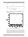
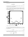
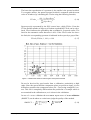
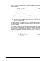
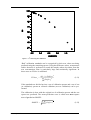
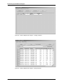
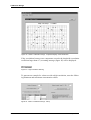
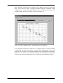
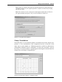
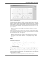
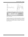
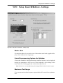
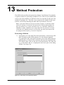
1
Version 6
User Manual
QUANT
© 2006 BRUKER OPTIK GmbH, Rudolf-Plank-Str. 27, D-76275 Ettlingen, www.brukeroptics.com
All rights reserved. No part of this publication may be reproduced or transmitted in any form or by any
means including printing, photocopying, microfilm, electronic systems etc. without our prior written
permission. Brand names, registered trade marks etc. used in this manual, even if not explicitly marked
as such, are not to be considered unprotected by trademarks law. They are the property of their respective owner.
The following publication has been worked out with utmost care. However, Bruker Optik GmbH does
not accept any liability for the correctness of the information. Bruker Optik GmbH reserves the right to
make changes to the products described in this manual without notice.
This manual is the original documentation for the OPUS spectroscopic software.
Table of Contents
About this Manual . . . . . . . . . . . . . . . . . . . . . . . . . . . . . . . . . . . . . . . . . .1
1
Introduction to multivariate Calibration . . . . . . . . . . . . . . . . . . . . . . . .3
2
Theoretical Background. . . . . . . . . . . . . . . . . . . . . . . . . . . . . . . . . . . . . .5
3
Chemometric Models and their Validation . . . . . . . . . . . . . . . . . . . . .13
3.1
3.2
3.3
Choosing Calibration Samples . . . . . . . . . . . . . . . . . . . . . . . . . . . . . . . . . . . 14
Acquiring Spectra and Data Preprocessing . . . . . . . . . . . . . . . . . . . . . . . . . . 16
Validating the Model . . . . . . . . . . . . . . . . . . . . . . . . . . . . . . . . . . . . . . . . . . . 18
4
Setting up a Calibration Method . . . . . . . . . . . . . . . . . . . . . . . . . . . . . .19
5
Validating the Model . . . . . . . . . . . . . . . . . . . . . . . . . . . . . . . . . . . . . . .27
5.1
5.2
Performing the Validation . . . . . . . . . . . . . . . . . . . . . . . . . . . . . . . . . . . . . . . 27
Taking a closer Look at the Results. . . . . . . . . . . . . . . . . . . . . . . . . . . . . . . . 31
6
Improving the Model . . . . . . . . . . . . . . . . . . . . . . . . . . . . . . . . . . . . . . .35
7
Generating a Report and Saving the Method. . . . . . . . . . . . . . . . . . . .43
8
Performing a quantitative Analysis. . . . . . . . . . . . . . . . . . . . . . . . . . . .49
9
Calibration Design . . . . . . . . . . . . . . . . . . . . . . . . . . . . . . . . . . . . . . . . .53
10
Reference Section . . . . . . . . . . . . . . . . . . . . . . . . . . . . . . . . . . . . . . . . . .59
10.1
10.2
10.3
10.4
10.5
10.6
10.7
10.8
10.9
10.10
10.11
10.12
10.13
10.14
10.15
10.16
Setup Quant 2 Method – Load Method . . . . . . . . . . . . . . . . . . . . . . . . . . . . . 59
Setup Quant 2 Method – Components. . . . . . . . . . . . . . . . . . . . . . . . . . . . . . 60
1Setup Quant 2 Method – Spectra . . . . . . . . . . . . . . . . . . . . . . . . . . . . . . . . . 62
Setup Quant 2 Method – Parameters . . . . . . . . . . . . . . . . . . . . . . . . . . . . . . . 72
Setup Quant 2 Method – Validate . . . . . . . . . . . . . . . . . . . . . . . . . . . . . . . . . 82
Setup Quant 2 Method – Graph . . . . . . . . . . . . . . . . . . . . . . . . . . . . . . . . . . . 84
Setup Quant 2 Method – Report . . . . . . . . . . . . . . . . . . . . . . . . . . . . . . . . . . 93
Setup Quant 2 Method – Store Method . . . . . . . . . . . . . . . . . . . . . . . . . . . . . 95
Setup Quant 2 Method – Optimize . . . . . . . . . . . . . . . . . . . . . . . . . . . . . . . . 97
Setup Quant 2 Method – Settings . . . . . . . . . . . . . . . . . . . . . . . . . . . . . . . . 102
Quantitative Analysis. . . . . . . . . . . . . . . . . . . . . . . . . . . . . . . . . . . . . . . . . . 104
Quant 2 Analysis / File List – Methods . . . . . . . . . . . . . . . . . . . . . . . . . . . . 106
Quant 2 Analysis / File List – Spectra . . . . . . . . . . . . . . . . . . . . . . . . . . . . . 107
Quant 2 Analysis / File List – Analysis Results . . . . . . . . . . . . . . . . . . . . . 108
Quant 2 Analysis / File List - Graph . . . . . . . . . . . . . . . . . . . . . . . . . . . . . . 109
Quant 2 Analysis / File List - Statistics . . . . . . . . . . . . . . . . . . . . . . . . . . . . 110
11
Abbreviations and Formulas . . . . . . . . . . . . . . . . . . . . . . . . . . . . . . . .111
12
21 CFR part 11 Compliance. . . . . . . . . . . . . . . . . . . . . . . . . . . . . . . . .115
12.1
12.2
Signing Spectra . . . . . . . . . . . . . . . . . . . . . . . . . . . . . . . . . . . . . . . . . . . . . . 115
Signing Methods . . . . . . . . . . . . . . . . . . . . . . . . . . . . . . . . . . . . . . . . . . . . . 116
13
Method Protection . . . . . . . . . . . . . . . . . . . . . . . . . . . . . . . . . . . . . . . .119
14
Spectra Transfer . . . . . . . . . . . . . . . . . . . . . . . . . . . . . . . . . . . . . . . . . .125
14.1
14.2
14.3
Setting up a Spectra Transfer Method . . . . . . . . . . . . . . . . . . . . . . . . . . . . . 125
Transferring Spectra . . . . . . . . . . . . . . . . . . . . . . . . . . . . . . . . . . . . . . . . . . 130
Setting up a Quant 2 Method using transferred Spectra . . . . . . . . . . . . . . . 131
About this Manual
This manual is divided into four parts. The first part (chapter 1 to 3) explains the
theory of the OPUS/QUANT software. Moreover, it contains information about
multivariate calibration, the different kinds of validation and data preprocessing
methods.
The second part (chapter 4 to 9) is a tutorial, that provides a step by step introduction to the QUANT analysis using the example data provided on the OPUS
CD. (You will find these data under ...\ENHANCED_DEMODATA\Quanttutorial.) In this way, you can reproduce the examples on your own computer while
working through the corresponding chapters of the manual.
The third part (chapter 10 to 11) servers primarily as a reference you can consult
if you have questions about a function or a particular problem with operating
the OPUS/QUANT software. Chapter 10 describes all QUANT functions in a
systematic manner. Chapter 11 provides definitions and mathematical formulae
of the statistical parameters that are relevant to the assessment of a QUANT
method.
The fourth part of the manual describes how to sign spectra and methods in
order to fulfill the 21 CFR part 11 requirements (chapter 12), how to protect a
method (chapter 13) and how to transfer spectra that have been acquired with a
different spectrometer system (chapter 14).
Bruker Optik GmbH
OPUS/QUANT
1
2
OPUS/QUANT
Bruker Optik GmbH
1
Introduction to multivariate
Calibration
This introduction is intended to familiarize you with the concept of the multivariate calibration analysis, on which the QUANT software is based. The
OPUS/QUANT software package is designed for the quantitative analysis of
spectra consisting of bands showing considerable overlap. Usually, they originate from samples containing one or several components in a matrix. The software allows to determine the concentration of more than one component in each
sample simultaneously. For this purpose, QUANT uses a partial least square
(PLS) fit method.
The purpose of calibration techniques is to correlate measured quantities like
the absorption of infrared radiation with properties of the system, for example,
the concentration of one component in a multicomponent system. Usually, two
steps are required: the calibration of the method and the analysis to determine a
value of an unknown sample.
Let us first take a look at the univariate calibration analysis, a method well
known in analytical laboratory work. For calibrating the system, a set of calibration samples needs to be measured. The concentration of the substance in question contained in the calibration samples has to be known, e.g. it has to be
determined by a different analytical technique. Then, the height of a peak characteristic for the substance is determined from the spectra and plotted versus the
known concentrations. The resulting graph will be used to evaluate the concentration of an unknown sample by measuring the peak height and reading the
corresponding concentration from the graph. In order to analyze multicomponent samples, a signal characteristic for each component must be used for the
calibration and analysis. These signals must be well separated to be indicative.
Univariate calibrations suffer from the following disadvantages:
• Outliers or perturbations caused by additional unknown components
are not recognized because the concentration of the analyte is determined in one spectral point only.
• Statistical fluctuations caused by detector noise are directly reflected
by the concentration values. Therefore, measurements have to be
repeated several times.
• Peaks used for the analysis of multicomponent systems must be well
separated, which is a severe drawback in NIR spectroscopy.
• The analysis of multicomponent systems assumes the validity of the
Lambert Beers law, i.e. a linear correlation between the concentration and the spectral response. This does not account for temperature
fluctuations or intermolecular interactions.
Bruker Optik GmbH
OPUS/QUANT
3
Introduction to multivariate Calibration
Multivariate calibrations make use of not only a single spectral point but take
into account spectral features over a wide range. Therefore, the analysis of overlapping spectral bands or broad peaks becomes feasible. The information contained in the spectra of the calibration samples will be compared to the
information of the concentration values using a PLS regression. The method
assumes that systematic variations observed in the spectra are a consequence of
the concentration change of the components. However, the correlation between
the components concentration and the change in the infrared signal does not
have to be a linear one.
Multivariate calibrations require a large number of calibration samples and
yield a large amount of data (several spectra with hundreds or thousands of relevant data points). In order to conveniently handle the data, the spectral data
and the concentration data are written in the form of matrices, where each row
in the spectral data matrix represents a sample spectrum. The concentration data
matrix contains the corresponding concentration values of the samples. The
matrices will be broken down into their Eigenvectors which are called factors or
principal components. The advantage of this approach is, that not all of the principal components are necessary to describe the relevant spectral features; for
example some of these vectors simply represent the spectral noise of the measurement. Only the relevant principal components will then be used instead of
the original spectral data, thus leading to a considerable reduction of the amount
of data. A PLS regression algorithm will be deployed to find the best correlation
function between spectral and concentration data matrix.
The determination of the number of principal components is a crucial point for
the quality of the calibration model. Using an insufficient number of principal
components leads to a poor reproduction of the spectral data and therefore the
model will not be able to recognize changes in the spectral features. This is
called “underfitting”. On the other hand, including too many principal components just adds spectral noise to the regression and does not increase the amount
of valuable information (“overfitting”).
Multicomponent systems can be analyzed either for each component separately
(PLS 1 algorithm) or simultaneously for all components (PLS 2 algorithm).
However, the PLS 1 analysis usually yields better results, and therefore is
mainly used for multivariate calibrations. QUANT exclusively uses the PLS 1
algorithm. Details about the theory behind the multivariate calibration and its
implementation in QUANT are described in chapter 2.
4
OPUS/QUANT
Bruker Optik GmbH
2
Theoretical Background
In general, the aim of a quantitative analytical method is to determine the property Y of a system from an experimentally observable X, whereby X and Y are
correlated by a calibration function b.
Y = X⋅b
(2-1)
Y1
Spectrum 1
Y2 = Spectrum 2 ⋅ b
(2-2)
....
....
Y3
Spectrum 3
The vector Y consists of the component values (of a single component) as determined by the reference measurements. The row vectors of the matrix X are
formed from the calibration spectra. The aim is to determine the vector b. When
b is known, the prediction of unknown values for Yn can be done.
The solution of the above system of equations is given by:
T
b = (X ⋅ X)
–1
T
⋅X ⋅Y
(2-3)
The PLS Method
During PLS regression, the matrices X are reduced to only a few factors. The
difficulty is the inversion of the matrix XTX. The PLS method involves the calculation of a restricted inverse instead of the complete. PLS requires the matrix
X is bi-diagonalized:
X = UBV
T
(2-4)
The matrices U and V are orthonormal, and B is of bi-diagonal form. This can
also be expressed as:
X = TV
T
(2-5)
The elements of the matrix T are known as “scores” and the PLS vectors are
sometimes called “loadings.”
A starting vector ν1 for the PLS analysis is chosen:
T
X Y
v 1 = -------------T
X Y
Bruker Optik GmbH
OPUS/QUANT
(2-6)
5
Theoretical Background
The first PLS vector shows the correlations between the component values and
the spectral intensities of the calibration spectra. The PLS analysis can be terminated if the component values Y are reproduced in a consistent way with the
help of the vector b (regression).
The number of PLS vectors used is defined in the QUANT program by the size
of the “rank”. Optimum PLS rank can be calculated only if the number of calibration spectra is sufficiently high (e. g. one component and 20 calibration
spectra). The PLS regression has the advantage that the PLS factors are
arranged in correct sequence, according to their relevance to predict the component values. The first factor explains the most drastic changes of the spectrum.
The residual (Res) is the difference between the true and the fitted value. Thus
the sum of squared errors (SSE) is the quadratic summation of these values.
SSE =
∑ [ Resi ]2
(2-7)
The root mean square error of estimation RMSEE is calculated from this sum,
with M being the number of standards and R the rank:
RMSEE =
1 ---------------------SSE
M–R–1
(2-8)
The coefficient of determination (R²) gives the percentage of variance present in
the true component values, which is reproduced in the regression. R² approaches
100% as the fitted concentration values approach the true values:
⎛
⎞
2
SSE
R = ⎜ 1 – ------------------------------⎟ × 100
⎝
∑ ( y – y )2⎠
i
(2-9)
m
R² can be negative. This is true (in some cases) for low ranks, when the residuals are larger than the variance in the true values (yi):
The sum of residuals (SSE) decreases with increasing rank, so R² approaches a
limiting value of 100%.
An important measure is the Leverage value (hi):
T
h i = diag ( UU )
(2-10)
The hi values are a measure of the influence a spectrum has on the PLS model
for a particular component. A large value can arise if a spectrum has been measured under irregular conditions.
6
OPUS/QUANT
Bruker Optik GmbH
The hi values are always smaller than 1 and the total sum of all hi is equal to the
rank (R):
∑ hi
= R
(2-11)
R/M is the mean leverage value. 5 R/M is generally a suitable limit for detecting
outliers.
If the hi value is bigger than the indicated limit:
⋅ RankLimit = Factor
----------------------------------M
(2-12)
the spectrum should possibly be removed from the list of standards. Factor can
range between 2 and 10. Figure 1 is an example of the distribution of the leverage values for the calibration spectra.
Figure 1: Leverage Values Plotted against the Sample Number
The sequence of the leverage values as a function of the concentration is frequently parabolic for a one component system (see Figure 2). The lowest and
the highest concentration values have the largest leverage values. The leverage
values which are above the limit are not outliers as it might be suspected. The
user must be very careful in removing spectra from the calibration list for a one
component system.
Bruker Optik GmbH
OPUS/QUANT
7
Theoretical Background
The expression:
Factor
⋅ Rank----------------------------------M
(2-13)
is also used as a limit for the Mahalanobis distance “MahDist” which is calculated in the analysis of unknown samples.
A Factor of 2 has been found to be too conservative for analysis. Too many
spectra are marked as outliers, although the predicted component values are
OK. The variable Factor was introduced for setting a more realistic limit for the
outlier detection during analysis.
Figure 2: Leverage Values Plotted against the True Values
The measured calibration spectrum after the data preprocessing is represented
by xi and the spectrum reconstructed from the PLS vectors vr as si. ti,r are the
score coefficients:
si =
∑ t i, r v r
(2-14)
The spectral residual (“SpecRes”) is calculated by a summation of all selected
frequency points of the difference spectrum:
SpecRes =
8
∑ ( xi – si )2
OPUS/QUANT
(2-15)
Bruker Optik GmbH
The better the reproduction of a spectrum is, the smaller is the spectral residual.
To recognize outliers, the squared spectral residual is compared with the mean
value of all others (by calculating the FValue using the following formula):
2
( M – 1 ) ( SpecRes i )
FValue i = ------------------------------------------------∑ ( SpecResj )2
(2-16)
j≠i
Spectra poorly represented by the PLS vectors have a high FValue. From the
FValue and the number of degrees of freedom a probability FProb can be calculated. FProb indicates the probability that a standard is a spectral outlier. The
limit for the automatic outlier detection is 99%. If the FProb value lies above
the limit, the corresponding spectrum is indicated in the report by a grayed line:
FProb ( FValue, 1, M-1 ) > 0.99
(2-17)
Figure 3: Mahalanobis Distance Plotted against the Spectral Residual
Do not be deceived by good results from a calibration, particularly at high
ranks. Since the spectra and the component values are present as input, it is not
difficult to reproduce the component values (Fit = True) using enough PLS vectors. This fact is completely different than the prediction of a sample which is
not contained in the calibration set, as it is done in the validations.
In case of a cross validation the root mean square error of cross validation
(RMSECV) can be taken as a criterion to judge the quality of the method:
RMSECV =
Bruker Optik GmbH
1- M
2
---⋅
( Differi ) =
M i∑= 1
OPUS/QUANT
1---⋅ PRESS
M
(2-18)
9
Theoretical Background
In case of a test set validation this value is called the root mean square error of
prediction (RMSEP).
M
PRESS = ∑ ( Differi )
2
i=1
(2-19)
A recommendation for the optimal PLS rank is given, using these values, to prevent overfitting.
1) The rank with the smallest PRESS value is searched. (This presumes that
enough PLS ranks are calculated.)
2) For all lower ranks, the quotient of their PRESS values and the minimum
is calculated (= FValue).
3) From this FValue a probability is calculated: FProb (FValue, M, M).
4) The rank, having a probability smaller than 0.75 for the first time, is
marked as the optimum rank.
The PRESS calculation is meaningful only if there is a large number of calibration standards, because the set should not change significantly when reduced by
one or more standards.
The size of the prediction error is another important number. This value can be
judged only if the distribution of the component values is known. This is taken
into consideration in the calculation of R² and therefore is a direct measure for
the quality of the prediction. The relation between R² and RMSECV is not linear,
as figure 4 shows.
2
⎛
( Differ i ) ⎞⎟
∑
⎜
R = 1 – ------------------------------- × 100
⎜
⎟
∑ ( yi – ym )2 ⎠
⎝
2
10
OPUS/QUANT
(2-20)
Bruker Optik GmbH
Figure 4: R2 Plotted against RMSECV
“Bad” calibration standards can be recognized by their true values not being
predicted using the remaining spectra. Using the difference values, an automatic
outlier detection is performed to mark the samples whose deviation from the
true concentration value is particularly large and statistically significant. In
these cases an FValue is calculated.
2
( M – 1 ) ( Differ i )
FValue i = ------------------------------------------∑ ( Differi )2
(2-21)
j≠i
If the standards are divided up into a set of calibration spectra and a set of test
(or validation) spectra an external validation (test set validation) can be performed.
The calibration is done with the original set of calibration spectra and the test
spectra are predicted. The mean prediction error is called root mean square
error of prediction RMSEP:
RMSEP =
Bruker Optik GmbH
1
----- ∑ ( Differ i ) 2
M
OPUS/QUANT
(2-22)
11
Theoretical Background
To summarize, the setup of a reliable PLS model is an iterative process:
1)
2)
3)
4)
12
Look at the validation report to select a suitable rank.
For this rank remove possible outliers.
A new determination of the optimum rank is then necessary.
Several data preprocessing options should be tested and the selected frequency regions should be changed.
OPUS/QUANT
Bruker Optik GmbH
3
Chemometric Models and
their Validation
The purpose of QUANT is the quantitative analysis of an unknown multicomponent sample. However, in order to perform an analysis, QUANT first has to
“learn” about your system. This means you have to develop a chemometric
model, using a number of calibration samples of known composition that are
representative for your system. The IR spectra of these samples will be used by
QUANT to calculate a calibration function, which essentially is the model used
for the analysis of unknown samples later. However, the model has to be evaluated to test its reliability of prediction (validation).
There are two validation types: “Cross Validation” and “Test Set Validation”.
While in the latter case two different sets of samples are used, the
Cross Validation uses the same set of samples for calibration and validation.
Cross Validation
Only one set of samples representative for your multicomponent system is used
to calibrate and validate your system. Before starting the calibration, one sample is excluded from the entity of samples. This sample is used for the validation. The remaining samples are used to calibrate the system. The sample used
for validating the system must not be part of the calibration set. Here is an
example to illustrate this point: let’s say you choose 100 samples of a known
composition. From these samples you take sample number 67 and set it aside.
The remaining 99 samples now make up your calibration set and you will use
them to create a chemometric model. After doing this you will test this model
against sample 67. Then you repeat this cycle, this time separating a different
sample (e.g. #17) and so on, until all samples have been used for validation
once. QUANT reiterates this cycle, starting with the first sample, until all samples have been used for validation.
The advantage of cross validation is the smaller number of samples required.
Especially, if the number of samples available is limited this method should be
preferred upon the test set validation.
Bruker Optik GmbH
OPUS/QUANT
13
Chemometric Models and their Validation
Calibration Set:
Developing a Method
Test Sample:
Validating the Method
Figure 5: Cross Validation
Test Set Validation
The test set validation uses two independent sets of samples, one for calibrating
the system and the other for validating the model. Both sets should consist of
about the same number of samples and each set should cover the whole concentration range of your system. Needless to say that a sample must not be included
in both sets.
The advantage of the test set method is the speed of calculation when dealing
with a very large number of samples. Sometimes this method is even required,
e.g. for governmental regulations.
Calibration Set:
Developing a Method
Test Sample:
Validating the Method
Figure 6: Test Set Validation
3.1
Choosing Calibration Samples
The first step of building a chemometric model is to pick a sufficiently large
number of samples to represent your system. These samples have to be quantitatively analyzed by a reliable method to determine their components. Then the
IR spectra of all samples are taken and, depending on the type of validation
method used, a calibration set and a test set is formed of these spectra.
14
OPUS/QUANT
Bruker Optik GmbH
Choosing Calibration Samples
The following rules should be observed when forming a calibration set:
• No general recommendation can be given concerning the number of
samples in a calibration set. As a rule of thumb, for a one component
system a minimum of 20 samples should be measured. Multicomponent systems require a larger number of calibration samples.
Note: For setting up a calibration model using OPUS/QUANT you can use up to
60000 spectra maximum.
• Choose your calibration samples in a way they cover a wider concentration range than you intend to analyze later. This helps to create a
more stable model for analysis.
This becomes increasingly important if you expect outliers, with concentrations that largely deviate from your desired values, as this may
be the case in quality control.
• The calibration samples should be spaced homogeneously across the
concentration range. Do not include samples with concentrations
well apart from the concentration field the majority of your samples
span. In case you need to extend the concentration range, include a
larger number of samples, so that the resulting range still retains the
sample density.
• Do not try to correct external fluctuations, as this will be mirrored as
concentration fluctuations in your samples. These fluctuations will
be recognized as such by QUANT and accounted for in the calibration function. This will yield a more robust model. Keep in mind that
an extensive sample preconditioning of the calibration samples will
have to be repeated later for every sample to be analyzed. Never try
to account for deviations in the calibration set you can not correct for
the samples you want to analyze. Rather increase the number of samples included in your calibration set.
• If your process conditions change later, there is no need to repeat the
calibration, because the perturbations will be “filtered” by the PLS 1
algorithm. If your concentration range expands in the future, simply
add a sufficient number of samples to the calibration set, covering the
new wider range.
• In case you prepare the samples for your calibration set in the lab,
make sure that these samples show no collinearity, which means that
they do not show a linear de- or increase in concentration of the components. Especially dilution series are not suited as calibration samples.
Bruker Optik GmbH
OPUS/QUANT
15
Chemometric Models and their Validation
1%A
2%B
3%C
2%A
4%B
6%C
3%A
6%B
9%C
1%A
2%B
3%C
5% A
12 % B
1% C
13 % A
7% B
24 % C
Figure 7: Example of collinear Samples and Samples showing no Collinearity
• When acquiring spectra from the calibration set, never measure the
samples in increasing or decreasing order of their concentration. Otherwise, linear fluctuations in temperature (heating up or cooling of
the samples) or concentration (evaporation of solvent) will not be
recognized by the PLS 1 algorithm. If possible, repeat the measurements at a later point in time.
• Ensure that the reference method you use for the determination of the
components concentration yields reliable results. Repeat these measurements to obtain statistical significance. Be sure to know the statistical error of your reference method.
3.2
Acquiring Spectra and Data Preprocessing
After you have chosen a set of samples you need to acquire their IR spectra.
Check the reproducibility of the measurements, for short and long time intervals, using a few test samples first. Make sure to use the same parameter set
during the measurements of the calibration set that you later want to use
for the analysis.
Now that you have all spectra at your hand, you should decide on whether you
want to use the whole frequency region of the data and whether you want to perform some data preprocessing before starting the QUANT software.
Frequency Region
The PLS regression method is a “full spectrum method”; the chemometric
model should improve with an increasing number of data points. However, in
some cases spectral noise or additional components in the samples may cause
the PLS algorithm to interpret these features, which can degrade the model. In
these cases it is advisable to limit the frequency region used for the PLS regression. Usually this step is taken to improve a regression that did not yield a satis16
OPUS/QUANT
Bruker Optik GmbH
Acquiring Spectra and Data Preprocessing
factory model. When narrowing down a spectrum to a few absorption bands it is
found, that in general bands between 0.7 and 1.0 absorbance units (AU) generate the best results. Values greater than 2.5 should not be used. Also, it is not
necessary to identify substance specific peaks, but rather to include the complete frequency region of the functional groups (e.g. alcohols) from a spectrum.
Nevertheless, in case of a minor component, it can be helpful to know the
absorptions in the spectrum to find relevant frequency regions.
Data Preprocessing
Data preprocessing is an important stage in performing a calibration. To ensure
the reproducibility of the calibration samples, several spectra of each sample
have to be acquired. If the spectra of the same sample are not identical, a data
preprocessing procedure must be chosen to bring them into line with each other.
Data preprocessing can eliminate variations in offset or different linear baselines.
In quantitative analysis, it is assumed that the layer thickness (i.e. the effective
pathlength of the infrared light in the sample) is identical in all measurements.
A lack of reproducibility in sample preparation can easily cause variations in
sample thickness. If the thicknesses are different or unknown, this effect can be
eliminated by a normalization of the spectra. The purpose of data preprocessing
is to ensure a good correlation between the spectral data and the concentration
values. The following methods can be applied:
• Linear Offset Subtraction: shifts the spectra in order to set the y-minimum to zero.
• Straight Line Subtraction: fits a straight line to the spectrum and subtracts it. This accounts for a tilt in the recorded spectrum.
• Vector Normalization: normalizes a spectrum by first calculating the
average intensity value and subsequent subtraction of this value from
the spectrum. Then the sum of the squared intensities is calculated
and the spectrum is divided by the square root of this sum. This
method is used to account for different samples thickness, for example.
• Min-max Normalization: first subtracts a linear offset and then sets
the y-maximum to a value of 2 by multiplication with a constant.
Used similar to the vector normalization.
• Multiplicative Scatter Correction: performs a linear transformation
of each spectrum for it to best match the mean spectrum of the whole
set. This method is often used for spectra measured in diffuse reflection.
• First Derivative: calculates the first derivative of the spectrum. This
method emphasizes steep edges of a peak. It is used to emphasize
pronounced, but small features over a broad background. Spectral
noise is also enhanced.
• Second Derivative: similar to the first derivative, but with a more
drastic result.
Bruker Optik GmbH
OPUS/QUANT
17
Chemometric Models and their Validation
No general recommendation can be given whether a given data set should be
preprocessed or which method is suited best for it. Therefore, the optimal data
preprocessing method can only be found empirically by applying several methods to your spectral data and comparing the results.
3.3
Validating the Model
At this point the model needs to be validated. If a sufficient number of samples
have been measured, it is possible to divide the samples into two sets of about
equal number, a calibration set and a test set. The calibration set is used to build
up a model which is then tested with the test set. This procedure is called test set
validation. The distribution of the concentration values should be similar for
both sets. A test set validation requires less computational time than a cross validation.
If only a limited number of samples is available, use a cross validation (see
above). To perform a good cross validation the number of spectra per sample
should be equal for all calibration standards.
Important: Repetitive spectra of one sample must be assigned as “one sample”!
A matrix is formed from the spectral data of the calibration set. The matrix will
be transformed by the PLS 1 algorithm into a result matrix consisting of eigenvectors (factors) only, as mentioned above. These factors are sorted in decreasing order according to their contribution to the spectral features. Factors which
present a large contribution to the spectrum are found in the top rows of the
matrix, while factors listed towards the bottom rows mainly reflect spectral
noise and fluctuations. Thus not all factors are needed to explain the spectral
features of the components (the contributions representing noise can be omitted). The quality of the chemometric model now depends on the choice of the
correct number of factors needed; this is also called the rank of the model.
Choosing a too small rank results in underfitting so that not all features can be
explained by the model. On the other hand, including too many factors (rank too
high) leads to overfitting and only adds noise, in fact degrades the model.
As a consequence there is an optimum number of factors for every system, i.e.
an optimum rank. A criteria for determining the optimum rank is to look at the
root mean square error of prediction (RMSEP, see chapter 2 for details) resulting from an analysis of the test set (or the cross validation). If the RMSEP is
depicted against the rank used in each model, a minimum can be observed in
this graph, indicating the optimum rank.
18
OPUS/QUANT
Bruker Optik GmbH
4
Setting up a Calibration
Method
This chapter shows you how to set up a QUANT model using the data provided
on the OPUS CD under the path \ENHANCED_DEMODATA\Quanttutorial.
The demo data consist of spectra taken from a mixture of methanol, ethanol and
propanol. Spectra of the pure components as well as a spectrum of a mixture
containing equal parts of all alcohols are shown in figure 8.
As you can see, the spectra of these alcohols show considerable overlap of the
peaks. Four functional groups are distinguishable in the spectra: COH combination vibrations (around 4800 cm-1), the first overtones of the CH2 and CH3
groups (6000 cm-1 - 5500 cm-1), the first overtone of the COH groups
(8300 cm-1 - 6000 cm-1) and the second overtones of the CH2 and CH3 groups
(8800 cm-1 - 7800 cm-1). Above 9000 cm-1, there are no relevant signals.
Below 4000 cm-1, the spectra show a large amount of noise and the COH vibrations show a very strong absorption.
Propanol
Methanol
Ethanol
Mixture
Figure 8: NIR Spectra of Pure Ethanol, Methanol and Propanol as well as a Mixture of these Alcohols
Bruker Optik GmbH
OPUS/QUANT
19
Setting up a Calibration Method
The folder Quanttutorial contains 30 spectra acquired from 15 different samples. Each sample has been measured twice, for example 05Alk12.1 and
05Alk12.2 are two spectra taken from the same sample. These spectra are to
form the calibration set which will be used to perform a cross validation. Under
real conditions this set would most likely contain much more samples to yield a
more robust model.
1) Select Setup Quant 2 Method from the Evaluate menu. A window with a
number of pages opens and the first page (Load Method) is displayed.
This page allows you to load an existing Quant 2 method. In addition,
statistical information about the method is displayed. To create a new
method click on the Components tab.
Figure 9: Setup Quant 2 Method – Load Method Page
2) This page allows you to specify the components of your sample. Click
on the Add Component button to create a new entry in the list. The entry
will be named Comp. 1. You can change its name as well as the unit by
selecting it in the list and editing the Name and Unit fields. You can also
remove entries from the list by selecting them and pressing the Delete
key on your keyboard.
Now add three components, name them methanol, ethanol and propanol
and enter a unit (e.g. mg, %). In addition, you can specify the formatting
of the prediction value in the Quant 2 analysis report. You can choose
between Default Settings (5 Significant Digits) and Digits after the Decimal Point (i.e. you can specify the number of digits after the decimal
20
OPUS/QUANT
Bruker Optik GmbH
point) by clicking on the corresponding option button. The selected formatting option has an effect on the prediction values in Quant report of
the Quantitative Analysis 2 function (figure 90 and the analysis results
of the Quant 2 Analysis/File List function (figure 93). Note that the
selected option applies to all components.
Figure 10: Setup Quant 2 Method – Components Page
3) Click on the Spectra tab. As you can see, the table contains three columns labeled with the component names you have entered before. Now
load the spectra by click on the Add Spectra button. The Load File dialog box opens. Navigate to the Quanttutorial folder and load all spectra
05Alkx.*.
These spectra will be added to the table. Besides the component name
columns there are columns labeled data set, sample, path and file name.
Note that the first column indicates the spectrum number while in the
Sample column the sample numbers are listed. Except for the path and
file name entries, all other entries can be edited by clicking on the
respective table cell.
You can remove spectra from the table by selecting one or more (press
the Shift or Control key while selecting spectra) and using the Delete
key on your keyboard.
Calibration is the default setting in the column Data Set. Keep this setting because all spectra are intended for the calibration set. However,
you need to adjust the Sample column because every sample has been
measured twice, as mentioned above.
Bruker Optik GmbH
OPUS/QUANT
21
Setting up a Calibration Method
Figure 11: Setup Quant 2 Method – Spectra Page
4) Instead of editing each row manually, click on the Set Sample Numbers
button to change the numbering of the samples. The Set Sample Numbers window appears. Indicate how many spectra per sample you have
been acquired; in our example enter 2. Click on the Set button and then
on Exit button.
Figure 12: Set Sample Numbers Window
22
OPUS/QUANT
Bruker Optik GmbH
As a result, now two spectra are assigned to one sample.
Figure 13: Setup Quant 2 Method – Spectra Page
5) Enter the concentration values for each sample. The alcohol concentration values for all 15 samples are listed in Table 1. To facilitate this task,
you can duplicate identical entries by clicking on a cell. There will be a
small black square on the lower right corner of the cell. Position the cursor on this square. As a result, the pointer shape changes to a cross. Now
press the left mouse button while expanding the frame to the next cell in
order to copy the content of the cell. In this way, you can also copy a
row.
Figure 14: Copying Table Entries
Bruker Optik GmbH
OPUS/QUANT
23
Setting up a Calibration Method
6) To print the data you have entered, click on the Print button.
Table 1: Component Concentrations of Example Files.
File Name
Methanol [%]
Ethanol [%]
Propanol [%]
05Alk1.0/1
0
0
100
05Alk2.0/1
100
0
0
05Alk3.0/1
0
100
0
05Alk4.0/1
33.364
33.278
33.356
05Alk5.0/1
49.666
25.435
24.899
05Alk6.0/1
24.942
24.982
50.078
05Alk7.0/1
26.392
48.95
24.658
05Alk8.0/1
50.017
0
49.983
05Alk9.0/1
66.648
33.352
0
05Alk10.0/1
0
33.392
66.606
05Alk11.0/1
75.086
0
24.914
05Alk12.0/1
25.425
0
74.575
05Alk13.0/1
33.394
66.606
0
05Alk14.0/1
0
65.944
34.055
05Alk15.0/1
33.104
33.641
33.254
7) Avoid collinearity, i.e. ensure that the concentrations of the components
do not increase or decrease in the same way over the sample set. Otherwise, no independent calibration can be established. To check the correlation, click on the Comp. Correlations button. A window appears
showing the concentration distribution of the samples for each component pair.
24
OPUS/QUANT
Bruker Optik GmbH
Figure 15: Setup Quant 2 Method – Collinearity Check
In our sample set, the concentration values are evenly spread and no collinearity can be observed. The R2 value (squared correlation coefficient)
is well below 0.7, the threshold for correlation. If this value is above 0.7,
the following warning will be displayed:
In this case, a review of the prepared samples will be necessary. The
OPUS function Calibration Design helps you to find the optimal concentration values for a set of samples beforehand. (See chapter 7).
8) To generate a calibration model using the entered data click on the Validate tab.
Bruker Optik GmbH
OPUS/QUANT
25
Setting up a Calibration Method
26
OPUS/QUANT
Bruker Optik GmbH
Performing the Validation
5
Validating the Model
5.1
Performing the Validation
Proceed with the example of chapter 4. Click on the Validate tab.
Figure 16: Setup Quant 2 Method – Validate Page
1) The window comprises two group fields: the Validation Parameters and
the Calculation Status. Select the method used for the validation from
the drop-down list. You can choose between Cross Validation and Test
Set Validation, with cross validation being the default setting. For our
example, use this validation type. If you chose Test Set Validation
instead, you have to indicate on the Spectra page which samples form
the calibration set and which the test set.
2) As explained in chapter 3, a number of spectra has to be excluded from
the calibration set that will serve as internal test samples. Specify the
number of samples to exclude per cycle in the No. of samples leaving
out field. For our example, use the default setting 1 (a “sample” might
consist of several spectra, see figure 13).
Bruker Optik GmbH
OPUS/QUANT
27
Validating the Model
3) The table lists the components you have entered on the Components
page. The validation will be performed only for the components selected
with the check box. This may be useful in case you are interested only in
a few components to save processing time. Since our calibration set consists of only 30 spectra, use all components for the validation.
4) You can limit the rank to a maximum number, which is specified in the
Max. Rank column. Enter the value 10 for all components. Although
experience has shown that this rank might be too high for a 3 component
system, we recommend using it to get a feeling for this function.
5) Start the validation by clicking on the Validate button. This will bring up
a dialog box prompting you to enter a name for the validation run, with
Validation No x being the default setting. After clicking on the OK button the validation starts.
Figure 17: Setup Quant 2 Method – Set Validation Name
If you are working in a 21 CFR part 11 validated environment and your
spectra are not signed, an error message will occur. (For detailed information about singing spectra and methods refer to chapter 8.)
6) The progress of the calculation is indicated by the status bar. As you can
see, the algorithm runs separately for each component you have indicated before. As soon as the calculation is finished, the result will automatically be displayed by switching to the Graph page.
28
OPUS/QUANT
Bruker Optik GmbH
Performing the Validation
Figure 18: Setup Quant 2 Method – Validation in Progress
7) Figure 19 shows the diagrammatic representation of the validation
result. By default, the predicted concentration values versus the true
concentration values (i.e. the concentration values you have entered on
the Spectra page) are displayed. Outliers are marked in red. The recommended rank Rec. is in our case 6. The results of the predicted concentration values are displayed for this rank, but the display can be changed
by selecting a different rank in the Rank drop-down list. In addition, the
name of the validation, the component for which the result is shown, as
well as the values for RMSECV (root mean square error of cross validation) and R2 (coefficient of determination) are displayed. (For detailed
information refer to chapter 2).
8) Select the option RMSECV/Rank from the drop-down list to get a diagram displaying the RMSECV versus the rank. The value of the recommended rank is indicated in a different color.
Bruker Optik GmbH
OPUS/QUANT
29
Validating the Model
Figure 19: Setup Quant 2 Method – Display of the Predicted against the True Concentration Values
Figure 20: Setup Quant 2 Method – Display of RMSECV against the Rank
30
OPUS/QUANT
Bruker Optik GmbH
Taking a closer Look at the Results
5.2
Taking a closer Look at the Results
The validation has yielded a RMSECV value of 0.636 for the methanol concentration which is reasonable, considering the fact, that the whole frequency
region of the spectra has been used, including the spectral noise as well as the
region showing total absorption. The next chapter shows you how the model
can be improved.
But let us have a closer look at the validation results first. Switch back to the
first graph (Prediction/True). The straight line represents a prediction without
any error, that is, the predicted concentration values equal the concentration values of the test samples. Now enlarge a part of the graph by left-clicking in the
graph and drawing a frame around the area of interest. As you can see, the predicted values lie close to the line but not all of them actually match the line.
Figure 21: Enlarging a Region of the Graph
Bruker Optik GmbH
OPUS/QUANT
31
Validating the Model
Select the respective components from the drop-down list to display the results
for the other components. Note that the recommended rank remains the same
although the RMESCV values are different.
Now display the result for the first rank by selecting 1 from the Rank drop-down
list. The result for a model using only one factor of the matrix to analyze the
internal test samples is shown. Obviously, the prediction is not very useful and
the model needs to be improved. Select different ranks and notice the improvement of the prediction by either looking at the match between the predicted and
the true concentration values or at the RMSECV values. Browse between these
ranks by placing the cursor in the Rank drop-down list and using the arrow keys
of keyboard. If you position the cursor on one of the data points, its x and y values as well as the sample name are displayed.
Rank 1
Rank 2
Figure 22: Results for Models Employing 1 and 2 Factors
32
OPUS/QUANT
Bruker Optik GmbH
Taking a closer Look at the Results
Rank 4
Rank 10
Figure 23: Results for Models Employing 4 and 10 Factors
As the quality of the model improves, it becomes increasingly difficult to distinguish the errors of prediction judging from these plots only. A better way of
determining the optimum rank is plotting the RMSECV values versus the rank.
Switch to the RMSECV/Rank plot. Apparently, the model improves drastically
up to the rank 4, with rank 5 and 6 still giving slightly better predictions. However, ranks higher than 6 barely improve the model and basically represent the
addition of fluctuations (noise, temperature differences of the samples etc.)
which, in fact, eventually leads to a degradation of the result. It also becomes
clear that a calculation up to rank 10 would have been sufficient to determine
the optimum rank. Restricting the calculation to lower ranks saves processing
time as the calibration set contains more samples.
Bruker Optik GmbH
OPUS/QUANT
33
Validating the Model
Figure 24: RMSECV Plot and Enlargement of the Plot
In the following chapter we will improve the model by restricting the frequency
region and performing a data preprocessing.
34
OPUS/QUANT
Bruker Optik GmbH
6
Improving the Model
The first step in improving a chemometric model is to focus the PLS regression
on groups that contain information significant for the system. From the explanation in chapter 4 you have learned that the region below 4400cm-1 does not contain any useful spectral information as noise prevails. The peak around
4800 cm-1 shows a very strong absorption and should, therefore, also not be
included. In addition, you should limit the frequency region to 9000cm-1,
because above this value there are not any spectral information.
1) To repeat the validation, you need not set up the entire Quant method
once again. Just switch to the Parameters page and change the frequency range limits.
2) You can specify the frequency range limits by either entering the values
into the table or clicking on Interactive Region Selection button.
Figure 25: Setup Quant 2 Method – Choosing Frequency Region Limits
Bruker Optik GmbH
OPUS/QUANT
35
Improving the Model
3) A separate window opens displaying the spectra. You can add a new frequency region by right-clicking on the window and selecting the Add
Region function. The frequency region marked by a white background
will be used for the calculation. You can move the borders of the
selected frequency region by positioning the cursor on them and sliding
them while pressing the left mouse button.
Figure 26: Interactive Frequency Range Selection
4) In this example, use only one continuous frequency region. Set the maximum wave number to 9000 cm-1 and the minimum wave number to
5300 cm-1. After clicking on the OK button the interactively defined frequency region(s) are added to the table.
36
OPUS/QUANT
Bruker Optik GmbH
5) Select the option No Spectral Data Preprocessing, switch to the Validate page and start the validation.
6) The second validation run yields a rank similar to the one of the first validation run, but the RMSECV value has improved to 0.197. Furthermore, looking at the RMSECV/Rank plot a prominent minimum can be
observed.
Figure 27: Validation Result after Limiting the Frequency Region
Bruker Optik GmbH
OPUS/QUANT
37
Improving the Model
Figure 28: Result of Validation after Limiting the Frequency Range – RMSECV vs. Rank
7) In the next step, apply a preprocessing routine to the data prior to the
validation run. To do this, switch to the Parameter page and select Second Derivative (17 smoothing points) from the drop-down list. (Do not
change the frequency region.) Now start another validation run. As you
can see, the RMESCV value (0.139) has further improved, while the
optimum rank is still 7.
38
OPUS/QUANT
Bruker Optik GmbH
Figure 29: Result of the Validation when Using the Second Derivative of the Spectra
No general recommendations can be given as to which data preprocessing method should be used. The best method has to be found empirically
by trial and error. The following table compares the validation results
for different preprocessing methods applied to different frequency
regions.
Table 1: Comparison of Different Data Preprocessing Methods
Validation #
Data
Preprocessing
Frequency
Region [cm-1]
Rank
RMSECV
1
none
9000-5300
7
0.167
2
Straight Line
9000-5300
6
0.155
3
First Derivative
9000-5300
6
0.147
4
Second Derivative
9000-5300
7
0.120
5
none
7600-5300
7
0.164
6
First Derivative
7600-5300
5
0.163
7
Second Derivative
7600-5300
6
0.147
Bruker Optik GmbH
OPUS/QUANT
39
Improving the Model
The examples in table 1 show that a chemometric model can easily be
improved if reasonable spectroscopic assumptions are included in the
analysis. However, you can also have the QUANT software perform the
optimization for you. On the Optimize page the QUANT software automatically checks common frequency regions in combination with several data preprocessing methods. The results of the optimization
procedure together with the used parameters are listed in the window.
Note that the software yields only a list of the used parameters (frequency region and preprocessing method) as well as the resulting
RMSECV value and the rank; the choice of the best parameters to be
used for the validation is still the responsibility of the user. Depending
on the amount of data, the optimization procedure will take a considerable amount of time. In case of a test set validation, it takes several minutes to perform an optimization, while in the case of a cross validation
the optimization may take hours.
8) Go to the Optimize page and click on the Optimize button to start the
optimization procedure. The progress of the optimization is indicated by
a status bar. The data processing methods in combination with the frequency region as well as the RMSECV value and optimum rank are
listed in the window. If you click on the header of one of the first two
columns you get the list sorted according to the values of this column.
As already mentioned, it is the responsibility of the user to choose the
optimal parameter set. Repeat the validation using the selected parameter set. To do this, click on the corresponding row and then on the Use
Parameters button. As a result, these parameters are automatically
pasted into the respective fields on the Parameter page and the software
switches to the Validate page.
9) On the Settings page you can restrict the maximum frequency region and
select the data preprocessing methods used for the optimization.
40
OPUS/QUANT
Bruker Optik GmbH
Figure 30: Result of the Optimization
Bruker Optik GmbH
OPUS/QUANT
41
Improving the Model
42
OPUS/QUANT
Bruker Optik GmbH
7
Generating a Report and
Saving the Method
After you have created a chemometric model it is expedient to document the
parameters of the method. The QUANT software gives you the opportunity to
generate a report file that contains all important information about the Quant
method.
1) Click on the Report tab. The results of all validation runs you have performed so far are listed. You can display the results of the individual
validation runs by selecting the respective validation name in the dropdown list.
2) Similar to the Graph page, there are several drop-down lists allowing to
change the rank, the component and the type of result. The recommended rank is also displayed. The results are listed in a table instead of
being represented graphically. Select the result of the last validation
(Validation No 3) in the True-Prediction view.
For each spectrum of the calibration set you find next to the file name
the true concentration value and the predicted one as well as the difference of both values.
Figure 31: Setup Quant 2 Method – Report Page
Bruker Optik GmbH
OPUS/QUANT
43
Generating a Report and Saving the Method
3) Now select Validation Report from the drop-down list (figure 32). The
view changes; instead of the table, a print-ready validation report is displayed. (See figure 33.)
Figure 32: Setup Quant 2 Method – Switching to the Validation Report View
For each component of your multicomponent mixture a separate report
can be generated. These reports contain general and specific information
about the selected component as well as the used frequency region.
44
OPUS/QUANT
Bruker Optik GmbH
Figure 33: Setup Quant 2 Method – Validation Report View
4) To print this report you can click either on the Print or on the Window
button. Clicking on the Window button embeds the QUANT setup assistant in an OPUS window (figure 34). (The same Window button for the
QUANT Setup Assistant is also on the Graph and Spectra page.) Then,
choose the Print... command from the OPUS Print menu.
If you want to copy the whole report to the clipboard, mark the report by
clicking on the upper left tile in the validation report (see figure 33) and
press Ctrl + C on the keyboard. Then, you can paste the content of the
clipboard into any other application (e.g. Microsoft Word).
Notice that upon embedding the QUANT Setup Assistant into OPUS, a
control panel consisting of three buttons becomes active (figure 34).
Clicking on one of these buttons brings you back to the respective page
of the Setup Quant 2 Method dialog window. Click on the Report button
to return to the Report page.
Bruker Optik GmbH
OPUS/QUANT
45
Generating a Report and Saving the Method
Figure 34: Setup Quant 2 Method – Printing the Report
46
OPUS/QUANT
Bruker Optik GmbH
5) Finally, save the Quant 2 method you have created so far by switching to
the Store Method page. This page displays a summary of the relevant
information about the selected validation. You can store this information
including the validation results by activating the respective check box
and then clicking on the Store Method button. Thereupon, a method file
with the extension .q2 is generated that will be used to perform a
QUANT analysis. Note that only those components will be used for the
analysis of which the Use check box has been activated.
Figure 35: Setup Quant 2 Method – Saving the Method
6) The Select Validation Results window opens. Select the validation(s)
you want to store on the disk and click on the OK button. The standard
Save File dialog opens. Enter a file name and specify the target directory.
7) Now you have finished the setup of the Quant 2 method. Close the Setup
Quant 2 Method dialog window by clicking on the cross button in the
upper right corner.
Bruker Optik GmbH
OPUS/QUANT
47
Generating a Report and Saving the Method
48
OPUS/QUANT
Bruker Optik GmbH
8
Performing a
quantitative Analysis
Compared with setting up a Quant 2 method, the quantitative analysis of
unknown samples is an easy task. However, take into consideration that the
concentration values of the samples have to be within the concentration range
covered by the calibration set. Before you actually start the quantitative analysis, load the spectra of your unknown samples into the OPUS browser.
Select the Quantitative Analysis 2 function from the OPUS Evaluate menu. The
Quantitative Analysis 2 dialog box (figure 36) opens. Drag and drop the absorption block of the files you want to analyze from the OPUS browser in the File(s)
for Quantitative Analysis 2 field of the dialog window.
Load the Quant 2 method you want to use by clicking on the Load Quant 2
Method button. Note that a previously loaded method is automatically loaded. If
you want to use another method click on the Load Quant 2 Method button and
select another one. Then, click on the Analyze button to start the analysis.
Figure 36: Quant 2 Analysis
Bruker Optik GmbH
OPUS/QUANT
49
Performing a quantitative Analysis
The result of the quantitative analysis is appended to the respective file in form
of a QUANT report block. Clicking on this report block automatically opens a
report window. Select PLS Analysis Report to display the analysis results. The
upper subwindow displays the method file and information about the method
used. In the lower subwindow the predicted concentration value, the unit, the
Mahalanobis Distance (Mah. Dist.), the threshold value (Limit) for the outlier
identification and the Component Value Density of each component are listed.
(For detailed information refer to chapter 2.)
Figure 37: Quant 2 Report
The QUANT software also offers the possibility to automatically analyze several spectra at the same time. In addition, you can specify several methods used
for the quantitative analysis. To do this, select the Quant 2 Analysis /File List
instead of Quantitative Analysis 2 in the OPUS Evaluate menu. The following
dialog window opens:
50
OPUS/QUANT
Bruker Optik GmbH
Figure 38: Quant 2 Multiple File Analysis
1) Click on the Add Spectra button. A standard Load File dialog box
opens. Select the spectra you want to analyze. Upon confirming your
selection, these spectra are loaded and displayed in a table on the Spectra page.
2) Switch to the Methods page. Click on the Add Method button and select
one or several methods you want to use for the analysis. If you routinely
use the same set of methods you can store the set by clicking on the Save
Method List button.
3) Switch to the Analysis Results page and start the analysis by clicking on
the Analyze button. The QUANT software will process all files specified
on the Spectra page using all methods indicated on the Methods page.
The results are listed in form of a table on the Analysis Results page.
You can sort the list according to each column by double-clicking on the
respective column header. To print the analysis results click on the Print
button. In the field Print Title you can enter a title that will be printed
together with the report.
Bruker Optik GmbH
OPUS/QUANT
51
Performing a quantitative Analysis
Figure 39: Quant 2 Multiple File Analysis – Loading a Method
Figure 40: Quant 2 Multiple File Analysis – Analysis Results
52
OPUS/QUANT
Bruker Optik GmbH
9
Calibration Design
A major problem in preparing a sample set used for the calibration is to avoid
collinearity, i.e. that the concentration values of the sample components must
not decrease or increase proportionally to each other. In case of a two-component system, collinearity can not be avoided because, if the concentration of the
first component decreases, consequently, the concentration of the other component increases proportionally. In case of sample mixture containing three or
more components, a collinearity between two components can often not be
detected on first sight.
The Calibration Design function helps you to find the optimal concentration
distribution of sample components for a given number of samples and to avoid
collinearity. This function yields independent concentration values calculated at
random.
Select in the OPUS Evaluate menu the Calibration Design function. The following dialog box:
Figure 41: Quant 2 Calibration Design - Setup
Follow the instructions given in the right side of the dialog box: Select the number of components. Enter the wanted sum of the component values for one sample (normally 100). Specify the minimum and maximum concentration value
for each component. Note that the sum of the average values (minimum+maximum)/2 must be equal to the specified sum of component values. Enter the
component names and the number of samples (from 15 to 100 samples) you
want to include. Then, click on the Search Component Values button.
Bruker Optik GmbH
OPUS/QUANT
53
Calibration Design
By default, the software calculates an uniform distribution of the concentration
values, i.e. if the concentration range is divided into three subranges the number
of samples in the low, middle and high subrange is nearly equal. If you deactivate the corresponding check box the software searches a non-uniform distribution of the concentration values, if it is necessary (e.g. Comp. 1: 0-80, Comp. 2:
0-90, Comp. 3: 0-100, Comp 4: 0-10).
The following figure shows an example for a four-component system.
Figure 42: Quant 2 Calibration Design - Setup Page
After clicking on Search Component Values button, the QUANT software calculates an independent sample set, more precisely, the concentration values for
the components.These values are listed on the Table page in the dialog box:
54
OPUS/QUANT
Bruker Optik GmbH
Figure 43: Quant 2 Calibration Design - Table
The sum of the calculated component concentration values is constant for all
samples. Normally, the sum equals 100 (e.g. the sum of the component concentration values of a liquid sample is 100%), but can also be user-defined.
These optimized concentration values can be used to set up the calibration. The
table can be printed by clicking on the Print button or copied to the clipboard
(Ctrl+C) and pasted (Ctrl+V) into other applications.
On the Graph page, a graph showing the concentration distribution of the component pairs and the corresponding correlation coefficient are displayed. Select
the wanted component pair from the drop-down list.
Bruker Optik GmbH
OPUS/QUANT
55
Calibration Design
Figure 44: Quant 2 Calibration Design - Graphical Display of the Distribution
If the correlation between two components exceeds the threshold (correlation
coefficient larger than 0.7) a warning message (figure 45) will be displayed.
Figure 45: High Correlation Warning
To generate an example for a data set with a high correlation, enter the following minimum and maximum concentration values:
Figure 46: Quant 2 Calibration Design - Setup
56
OPUS/QUANT
Bruker Optik GmbH
After clicking on the Search Component Value button, switch to the Graph
page. As you can see, there is a high correlation between Component 2 and
Component 3, i.e. the concentration values are not distributed evenly over the
complete range but have the shape of a line. See figure 47.
Figure 47: Quant 2 Calibration Design - Graphical Display of the Distribution
The correlation coefficient is well above 0.7 and the High Correlation warning
is displayed. The chosen minimum and maximum concentration values (see
figure 46) do not allow to find concentration values without high correlation.
Therefore, you should enter different minimum and maximum concentration
values for one of these components (2 or 3) and repeat the calibration design.
Bruker Optik GmbH
OPUS/QUANT
57
Calibration Design
58
OPUS/QUANT
Bruker Optik GmbH
Setup Quant 2 Method – Load Method
10 Reference Section
10.1
Setup Quant 2 Method – Load Method
Figure 48: Setup Quant 2 Method – Load Method Page
Load Method
If you click on the Load Method button you can load an existing Quant 2
method. Quant 2 method files have the file extension .q2.
Note: Quant method files created with the OPUS-OS/2 QUANT software can
also be loaded. However, if you store such a method file using the OPUS/
QUANT software, this file can not be opened with OPUS-OS/2 QUANT any
longer. To avoid this, store the modified OPUS-OS/2 QUANT file under a different file name.
Bruker Optik GmbH
OPUS/QUANT
59
Reference Section
Load existing Validation Results
If an existing Quant 2 method has already been validated and the validation
results have been stored together with the method you can load these results by
activating the Load existing validation Results check box. Otherwise, only the
spectra, the components and the parameters of the method will be loaded when
you load the method file.
General Information
The General Information group field displays the statistical information about
the loaded Quant 2 method. The information includes the number of spectra
(calibration and test spectra) and the number of components used for the
method as well as the frequency region, the number of data points employed for
the validation and the used data preprocessing method.
10.2
Setup Quant 2 Method – Components
Figure 49: Setup Quant 2 Method – Components Page
60
OPUS/QUANT
Bruker Optik GmbH
Setup Quant 2 Method – Components
Add Component
Use the Add Component button to add a new entry to the components list. The
default name displayed in the Name field is Comp. x.
Name
The name of the component to be added or an selected entry of the list can be
changed in the Name field.
Unit
This field serves to specify the unit (with mg being the default setting) for the
component values.
Removing Components
To remove an entry from the list select this entry using the mouse and press the
Delete key on your keyboard.
Arranging Entries
The order of the components in the list can be changed by dragging the items
with the mouse.
Formatting in the Quant 2 Analysis Report
The formatting of the prediction value in the Quant 2 analysis report can be
specified. You can choose between Default Settings (5 Significant Digits) and
Digits after the Decimal Point (i.e. you can specify the number of digits after
the decimal point) by clicking on the corresponding option button. The selected
formatting option has an effect on the prediction values in Quant report of the
Quantitative Analysis 2 function (figure 90) and the analysis results of the
Quant 2 Analysis/File List function (figure 93). Note that the selected option
applies to all components.
Bruker Optik GmbH
OPUS/QUANT
61
Reference Section
10.3
Setup Quant 2 Method – Spectra
Figure 50: Setup Quant 2 Method – Spectra Page
Spectrum List
The table consists of several columns: data type (calibration, test, excluded),
sample number, target directory, file name and the names of the components
that you have defined on the Components page. Except for the Path and File
Name entries, all other entries can be edited by clicking on the respective table
cell.
You can select either one spectrum or several spectra separately or a block of
spectra. To select one spectrum, click on the numbered tile on the left side of the
table. To select several spectra separately, left-click on the numbered tiles while
pressing the CTRL-key. To mark a block of spectra, select the first by clicking
on the respective numbered tile, then select the last spectrum of the block by
left-clicking on it while pressing the Shift key. To mark the whole table click on
the upper tile on the left side (see circle in figure 50).
To rearrange the order of the spectra, select them, click on the tile and move
them to the new position while pressing the left mouse button. To sort the table
by a certain value (e.g. concentration value of methanol) double-click on the
column titles in the header.
62
OPUS/QUANT
Bruker Optik GmbH
Setup Quant 2 Method – Spectra
The column Data Set classifies whether a spectrum is assigned to the calibration
set, the test set, or, in case of an outlier, excluded from the data set. In this way,
you can exclude spectra from the validation without removing them from the
spectrum list. The default setting is Calibration. In case of a test set validation,
this setting assigns the spectrum to the calibration set. If you want to perform a
cross validation all spectra have to be part of the calibration set.
Figure 51: Assigning a Data Set Type
Add Spectra
Click on the Add Spectra button to open a Setup Quant 2 Method - Select Standards dialog box. Navigate to the target directory that contains the spectra used
for the QUANT 2 method and load all spectra of interest. These spectra will be
added to the table.
Set Sample Numbers
The spectra are numbered consecutively according to the order in which they
have been loaded. In practice, you mostly acquire more than one spectrum per
sample. Therefore, you have to adjust the numbering in the Sample column
accordingly. Click on the Set Sample Numbers button and specify how many
spectra belong to one sample (see figure 52). However, this requires that the
spectra of the same sample are listed in groups in the table (i.e. all spectra of
sample one, followed by all the spectra of sample two etc.).
Note: Take into consideration that a correct sample numbering (i.e. the correct
assignment of several spectra that belong to one sample) is of crucial importance
for the validation. If you have acquired different numbers of spectra per sample,
you have to apply different sample number settings on respective parts of the
spectra table. To do this, select only the first and the last row (e.g. row 9 and 17)
of that part of the spectra table to which you want to assign a different number of
spectra per sample than to the rest of the spectra table (by selecting the first spectrum of the part in question, pressing the CTRL-key and clicking on the last spectrum of the part of the spectra table).
To facilitate the sample number setting, activate the Set sample numbers
according to file names check box. In this case, files with the same file name
but a different extension are assigned to the same sample number.
Bruker Optik GmbH
OPUS/QUANT
63
Reference Section
Figure 52: Set Sample Numbers Dialog Box
Note: In case of file names containing date and time of the data acquisition, this
part of the file name is ignored by OPUS when setting the sample numbers
according to the file name. (See figure 53.)
Part of the file
name indicating date and
time of the data
acquisition
Figure 53: File Names containing Date and Time of the Data Acquisition
Change Path
This button allows you to change the path of your spectrum files. You can
change the path either for one spectrum file, several or all spectrum files. To do
this, you have to select the spectrum files in question before clicking on the
Change Path button, with one exception: if you want to change the path for all
spectrum files you need not select them.
To select one spectrum, click on the numbered tile on the left side of the table.
To select several spectra separately, left-click on the numbered tiles while
pressing the CTRL-key. To mark a block of spectra, select the first spectra by
clicking on the respective numbered tile, then select the last spectrum of the
block by left-clicking left while pressing the Shift key.
64
OPUS/QUANT
Bruker Optik GmbH
Setup Quant 2 Method – Spectra
Set Data Set
Clicking on the Set Data Set button brings up a dialog box (figure 54) allowing
to define the test set and calibration set used in a test set validation. By default,
all spectra are assigned to the calibration set. You can change the Data Set type
either manually by editing the table or automatically by assigning the test set
data type using this button.
Figure 54: Set Data Set
First Test Sample
This field is used to specify the beginning of the test set. If you have measured
120 sample spectra, for example, and spectra 1 to 69 form your calibration set,
while the remaining spectra are to be assigned to the test set, you have to enter
the value 70 in the First Test Sample field.
Block Length (Test Sample)
This field is used to define the number of the test set spectra. Taking the above
example, your test set comprises 50 samples. Therefore set the Block Length
(Test Samples) to 50 (or a larger value).
Gap (Calibration Samples)
So far we acted on the assumption that the spectra for the calibration set and the
test set are loaded as continuous blocks in the spectrum table. However, if the
spectra forming both sets are loaded alternating in the spectrum table, you can
still assign the spectra to the test set by specifying the spacing in the gap. The
assignment shown in figure 55 was created by specifying sample 3 as the First
Test Sample and setting the Block Length (Test Samples) and the Gap (Calibration Samples) to a value of 2.
Bruker Optik GmbH
OPUS/QUANT
65
Reference Section
Figure 55: Alternating Calibration Set and Test Set Spectra
Leave Excluded Spectra
If you activate the Leave ‘Exclude’ Spectra check box the spectra specified as
Excluded in the spectrum table will not be assigned to another data set (i.e. they
remain excluded).
Set Test Sample
After you have entered the values for First Test Sample, Block Length (Test
Samples) and Gap (Calibration Samples) click on the Set Test Sample button to
implement these settings in the spectra table.
Clear Test Spectra
Clicking on this button assigns all spectra to the calibration set.
Exchange Test ↔ Calibration
This function reverses the assignment of the spectra to the calibration and test
set.
Special Setting...
Spectra with a non-specified component value (indicated by a blank entry field
in the spectra list) or with a component value of 0 or -1 must be excluded from
the spectra list before you start the validation for the component in question. To
facilitate the exclusion of those spectra, select the component in question and
the corresponding option for the component value (blank, value 0 or value -1)
from the corresponding drop down lists. (See figure 56.) Afterwards, first click
on the Set button and then on the Exit button.
66
OPUS/QUANT
Bruker Optik GmbH
Setup Quant 2 Method – Spectra
Figure 56: Set Spectra on ’Excluded’
Automatic Selection of Test Samples
This function (figure 54) facilitates the assignment of the measured spectra to
the calibration set and the test set. The assignment is done automatically according to the selected value (in percentage) for the Test Samples. To use this function the following preconditions have to be fulfilled:
• No spectrum in the spectrum table has to assigned to the data set type
Test.
• The sample set has to comprise at least 16 samples.
• There have to be at least four different component values for each
component.
If there are already some test spectra you have to assign them to the calibration
set by clicking on the Clear Test Spectra button. Otherwise, you can not use this
function. If there are not enough samples (a minimum of 16 samples) or enough
different component values (a minimum of four different component values) for
a component you can also not use the Automatic Selection of Test Samples function.
If the above mentioned preconditions are fulfilled you can select a value percentage value from Test Samples drop-down list (e.g. the option 54 means that
54% of the sample set is assigned by the software to the test set). Click on the
Select Test Samples to effectuate the automatic selection of the test samples.
Set Selected Spectra on
This function facilitates the assignment of the spectra to certain data set type
(calibration, test or excluded) as all selected spectra are assigned to the specified
data set type at once.
Bruker Optik GmbH
OPUS/QUANT
67
Reference Section
You can use this function only if you have selected one or more spectra in the
spectrum table beforehand. Otherwise, this function is grayed (i.e. it is deactivated). To select one spectrum, click on the numbered tile on the left side of the
table. To select several spectra separately, left-click on the numbered tiles while
pressing the CTRL-key. To mark a block of spectra, select the first by clicking
on the respective numbered tile, then select the last spectrum of the block by
left-clicking left while pressing the Shift key.
Set Color on page Graph for selected Spectra
This function allows you to highlight one or more spectra by one or more different color(s). You can either choose an option of the drop-down list (blue,
magenta, orange, cyan or gray) or invoke a color palette by clicking on the
Color button. To implement the color setting in the spectra table click on the Set
Color button. To undo the color setting click on the Clear Color Setting button.
You can use this function only if you have selected one or more spectra in the
spectrum table beforehand. Otherwise, this function is grayed (i.e. it is deactivated). To select one spectrum, click on the numbered tile on the left side of the
table. To select several spectra separately, left-click on the numbered tiles while
pressing the CTRL-key. To mark a block of spectra, select the first by clicking
on the respective numbered tile, then select the last spectrum of the block by
left-clicking left while pressing the Shift key.
The color setting has an effect on the colored display of the data points on the
Graph page. If the Color check box in the left lower corner on the Graph page
is activated, the corresponding data points in the plot are displayed in the color
you have specified using this function.
Copy Spectra
The function Copy Spectra copies all spectra of the table and the current method
into the directory you have specified. Use this function if you want to archive
the method together with the spectra used. Either enter the path into the corresponding field or click on Select Path button to specify the target directory.
In case you have acquired several spectra per sample, this function provides an
additional opportunity: storing a new Quant method which is based on the mean
sample spectra. (See figure 57.) To do this, OPUS first calculates the mean
spectrum for each sample (using the full spectral range and the original spectra,
i.e. no preprocessed spectra) and then creates a Quant method file on the basis
of the calculated mean sample spectra. This newly created method file is stored
in the directory you have defined before by clicking on the Store New Method
button and specifying the path in the Store Quant 2 Method dialog window. The
proposed file name is <Name of the loaded method>_AV.q2. The mean spectra
are saved in the corresponding subdirectory <Name of new method>_Spectra.
The file name (including the extension) of the mean spectrum is taken over
from the first corresponding sample spectrum: <File name of first sample spectrum>_AV.
68
OPUS/QUANT
Bruker Optik GmbH
Setup Quant 2 Method – Spectra
Note: If there are samples with only one acquired spectrum, no mean spectrum is
calculated. In this case, the original spectrum is copied in new directory keeping
the same file name.
Note: The creation of a new, mean-spectra-based Quant method has no effects on
the original method and spectra. They are still available for further use.
Figure 57: Copy Spectra and Method
Comp. Correlations
Sometimes there is an unwanted collinear correlation between the sample components, i.e. the concentrations of the components increase or decrease in the
same way over the sample set. Collinearity must be avoided, as otherwise no
independent calibration can be established. To check the correlation, click on
the Comp. Correlations button. A graph appears showing the concentration distribution for each sample component pair.
Figure 58: Setup Quant 2 Method – Collinearity Check
Bruker Optik GmbH
OPUS/QUANT
69
Reference Section
In figure 58 the concentration values are evenly distributed and no collinear correlation can be observed. The R2 value (squared correlation coefficient) is
below 0.7, the threshold for correlation. If this value is above 0.7, the following
warning will be displayed:
In this case, a review of the prepared samples will be necessary. Use the OPUS
function Calibration Design (in the Evaluate menu) to find the best component
concentration values for a sample set beforehand. (See chapter 9.)
Window
Clicking on the Window button embeds the QUANT setup assistant in an OPUS
window. A dialog box comprising three buttons (Spectra, Graph and Report)
enables you to return directly to the Spectra, Graph or Report page of the Setup
Quant 2 Method dialog window.
Figure 59: Quant Report Window - Spectra List
At the bottom of the spectrum list, there is an empty row which can be used to
paste data from the clipboard to enlarge the spectra list. The fields Data Set and
Sample will be set automatically when you return to the Spectra page. The
fields Path, Filename and the component values can be edited. By default, Data
Set is set to Calibration and the Sample numbering is consecutive for the added
spectra.
70
OPUS/QUANT
Bruker Optik GmbH
Setup Quant 2 Method – Spectra
Entering Component Values
Component values can either be entered manually or pasted into the spectrum
list from the Windows clipboard. If you paste values into the table (using the
shortcut Ctrl + V) place the cursor in the table cell in which the first of the values is to be pasted.
To enter decimal numbers you can use both comma and dot. The QUANT software enables you to duplicate identical entries: to duplicate one row, select the
row in question by clicking on the cell and expanding the selection frame to the
whole row while keeping the left mouse button pressed. There is a small black
square on the lower right corner of the frame. Positioning the cursor on this
square changes the pointer shape to a cross. Now left-click on the square while
expanding the frame to the next row. Upon releasing the left mouse button the
values are copied in the next row.
Figure 60: Copying Table Entries
Removing Spectra
You can remove one or more spectra from the table by selecting them (press the
Shift or Control key while selecting the spectra in question) and pressing the
Delete key.
Bruker Optik GmbH
OPUS/QUANT
71
Reference Section
10.4
Setup Quant 2 Method – Parameters
Figure 61: Setup Quant 2 Method – Parameters Page
Preprocessing in individual Regions (PS)
When you activate the Preprocessing in individual regions (PS) check box and
click on the Set button the following dialog window opens:
Figure 62: Data Preprocessing in individual Regions
72
OPUS/QUANT
Bruker Optik GmbH
Setup Quant 2 Method – Parameters
The usage of this option implies a two-step data preprocessing procedure:
1. Step: Data preprocessing on the basis of your own defined preprocessing sequence, i.e. your own defined combination of preprocessing
method(s) and frequency region(s). (The individual preprocessing
sequence is defined in the dialog window shown in figure 62.)
Note: Defining an individual preprocessing sequence requires experiences in setting up a calibration method as OPUS does not check whether the self-defined
preprocessing sequence is appropriate. (For detailed information about the different data processing methods refer to chapter 1.)
2. Step: Data preprocessing on the basis of the frequency region(s) you
have defined for the calibration. (See the dialog window shown in
figure 61.) For this step, you can, but you need not necessarily select a
data preprocessing method.
Note: The spectra preprocessed in individual regions (step 1) are the basis for the
subsequent data preprocessing in calibration regions (step 2).
This two-step procedure allows an individual preprocessing of the original data
in the run-up to the actual calibration. In contrast to the fixed data preprocessing
options in the calibration regions, an additional data preprocessing in individual
regions provides a greater flexibility in combining data preprocessing methods
and frequency regions (e.g. a certain preprocessing method can be applied to a
different or a larger or a smaller frequency region than for the preprocessing in
the calibration regions).
To specify a preprocessing sequence, select the desired preprocessing method
from the drop-down list and define the frequency region by either entering the
values in the corresponding field or selecting the region interactively. (See
description below, section Interactive Region Selection.) Then, click on the Add
to List button. You can repeat this procedure several times. If you want to modify an item in the list later, mark this item by clicking on the corresponding
number, select a different method and/or specify another region and click on the
Modify Selected Item button. To delete the complete list, click on the Clear List
button.
Note: Do not use a Quant 2 method created with this option in a previous OPUS
version (Version 5.5 or lower).
Preprocessing in Calibration Regions
This drop-down list contains several data preprocessing methods. (For detailed
information about the data processing methods refer to chapter 1.) The selected
data preprocessing method is applied to the specified calibration region(s).
Mean Centering
If you activate this check box the mean spectrum and the mean component values are subtracted before the PLS model is performed. This scaling is advantageous. Choose it in almost all cases.
Bruker Optik GmbH
OPUS/QUANT
73
Reference Section
Calibration Regions
This table allows you to restrict the frequency region for the validation to one or
more frequency region(s). The limits of the frequency region(s) can either be
entered manually in the table or specified interactively by clicking on the Interactive Region Selection button.
Interactive Region Selection
If you click on this button the Select Frequency Range(s) window opens, displaying the calibration spectra. To specify a frequency region right-click on the
window and select the Add Region function from the pop-up menu.
The selected frequency region limits are indicated by gray borders. The spectral
range shown on the white background will be used for the preprocessing. You
can move the borders by placing the cursor on them and shifting them while
pressing the left mouse button. Positioning the cursor on the white area allows
you to shift the whole region in the same way. You can also add several frequency regions by right-clicking on the window and selecting the Add Region
function from the pop-up menu. To delete a region, call up the pop-up menu
again and select Remove. Alternatively, you can delete a region from the frequency table on the Parameters page. The pop-up menu also provides a zoom
function and a cross-hair cursor to conveniently get an exact reading of a spectral data point. (For detailed information refer to the OPUS Reference Manual.)
74
OPUS/QUANT
Bruker Optik GmbH
Setup Quant 2 Method – Parameters
Figure 63: Interactive Frequency Range Selection
Clear Selected Regions
You can remove an entry from the frequency regions table by selecting it and
clicking on the Clear Selected Regions button or pressing the Delete button of
the keyboard.
Display Preprocessed Spectra
Before starting the validation, it is possible to view the preprocessed spectra.
You can choose between the display of either all spectra or the spectra of every
xth sample or the spectra with a color flag. In the latter case, only the spectra
highlighted by color at the Spectra page are displayed. (For information about
how to highlight spectra by color see section 10.3, subsection Set Color on page
Graph for selected Spectra.)
Note: Take into consideration that loading a large number of spectra for the display will take some time. Therefore, in cases of a large number of spectra,
restricting the number of preprocessed spectra to be displayed is recommendable.
Moreover, the display of a huge number of spectra can reduce the discernability
of the individual spectra.
Click on the Display Preprocessed Spectra button. The following display window opens:
Bruker Optik GmbH
OPUS/QUANT
75
Reference Section
Figure 64: Display Preprocessed Spectra
The upper part of the window shows the spectra. All spectra are displayed, the
test spectra as well as the calibration spectra. Spectra which belong to the same
sample number have the same color. The default display limits of the window
are determined by the selected frequency regions on the Parameters page. The
current display limits can be changed by right-clicking and selecting
Properties → Display Limits from the pop-up menu.
The table in the lower part of the window contains all spectra and comprises
three columns. The left column lists the sample numbers and the right column
the spectrum filenames. In the Show column, you can select the spectra you
want to display in the graph by activating the corresponding check box.
The Go to Setup Quant button brings you back to the Parameter page. The
Interactive Region Section button has already been described above.
Sample Statistics
When you click on the Sample Statistics button (figure 61) the following window opens:
76
OPUS/QUANT
Bruker Optik GmbH
Setup Quant 2 Method – Parameters
Figure 65: Sample Statistics Plot
This plot shows the difference (RMS - root mean square) between each spectrum of a sample and the corresponding calculated mean spectrum versus the
sample number. It allows you to recognize outliers that occurred when measuring the same sample repeatedly and exclude them in the spectra list in the runup to validation.
Note: The evaluation is based on the selected frequency regions and the preprocessed spectra.
When you place the cursor in the plot on a data point, a tooltip appears containing the following information: sample number, spectrum number, file name and
the exact difference value. (See figure 65.)
Note: The sample statistics plot can only be displayed if the data set contains several spectra of each sample. Otherwise, a corresponding message window
appears.
PCA
The purpose of the PCA is:
• selecting optimally spectra for the test data set (as an alternative to
the procedure described in section 11.3, subsection Set Data Set),
• selecting suitable spectra for calibration set,
• getting an overview of the acquired spectra and
• recognizing outliers.
When you activate the PCA check box you can perform a Principle Component
Analysis (PCA). (See figure 61.) Similar to the PLS regression, the PCA is
intended to reduce the huge amount of acquired data and to describe it by as few
factors as possible. In contrast to the PLS regression, however, the component
values need not to be known.
Note: The PCA is calculated only on the basis of the calibration spectra.
Bruker Optik GmbH
OPUS/QUANT
77
Reference Section
During the PCA, the spectra data matrix is factorized, i.e. it is divided into two
matrixes: the factor matrix (loadings) and the score matrix. See the following
figure.
Figure 66: Factorization of the Spectra Data Matrix
During the factor analysis, a set of spectra is transformed in factors (loadings)
and the corresponding scores. The factor analysis is a variance analysis, i.e. the
differences between the spectra are determined and reproduced in form of factors. The first factor describes the as big as possible part of the whole variance,
the second factor the as big as possible part of the remaining variance and so on.
The part of whole variance that the following factors represent is becoming
smaller and smaller until they represent only noise.
The factors are orthogonal, i.e. they are independent so that a part of the information of the data set is represented by only one factor. As many factors are calculated as there are spectra in the data set. The factors are calculated for the
whole data set. In case you change the data set or the parameters (e.g. frequency
region, data preprocessing) the factors have to be calculated once again.
The scores contain the information about how the original spectra are described
by factors. For each spectrum there is a set of scores that describes the spectrum
on the basis of the calculated factors. By multiplying the score coefficients by
the corresponding factors and adding up the products, a spectrum can be reconstructed. The scores can be used for further evaluations as they represent the
spectral information of the original spectra on the basis of the loadings. Use
only the score values of the first factors as the higher factors represent only
noise and other non usable information.
The principle of the factor analysis is illustrated on basis of the following example: A data set consisting of five simple spectra, that have two overlapping
bands, are factorized. See figure 67. The calculated factor 1 includes the biggest
part of the information (principle variance) of the data set. The result of factor 1
is a factor spectrum that is similar to an mean spectrum. Factor 2 includes the
information about the two varying bands. To determine which band is more
78
OPUS/QUANT
Bruker Optik GmbH
Setup Quant 2 Method – Parameters
intensive, the sign of the scores has to be reversed. In case of this example data
set, two factors describe 99% of the information of the data set. So, the score
values of the first two factors are sufficient to describe the differences between
the spectra (i.e. 2 values per spectrum instead of 250 data points).
Figure 67: Result of a Factorization
Enter a value between 1 and 20 in the field Factors (the default value 5 is
acceptable for most cases) and click on the Factorize button to start the PCA.
See figure 61. The progress of the factor analysis is shown in the status bar.
The result of the PCA can be displayed using two diagrams: a score diagram
(figure 68) and a loading diagram (figure 69). Click on the corresponding button.
Figure 68: Score-Diagram
Bruker Optik GmbH
OPUS/QUANT
79
Reference Section
The scores indicate the position (coordinates) of the sample in a so-called factor
space. In case the samples are close to each other or they form clusters, these
samples have similar spectra.
If you have marked the calibration spectra on the Spectra page in different colors (see section 10.3, subsection Set Color on page Graph for selected Spectra)
you can have the spectra displayed in the specified colors also in the score diagram by activating the Color check box.
Note: If you have set some calibration spectra to Excluded or Test the color display is deactivated.
Use the score diagram to display the spatial distribution of the samples for the
different factors by selecting different factors in the X-Axis and Y-Axis dropdown list. On the basis of these displays, now determine the factors for the automatic selection of the subset.
This dialog window provides an alternative for selecting the spectra for the test
data set in the best possible or excluding spectra from both the calibration and
the test set. Select the appropriate factor(s), specify the subset (in %) for the
automatic selection of the subset (i.e. which spectra are to set to Test or
Excluded) and click on the Select Subset button. As a result, the program selects
automatically the spectra and marks them by a red asterisks. The selection is
done from the aspect of covering the whole concentration range in the best possible way to obtain a robust model. (To undo the selection click on the Exit button.) Specify whether the spectra, that are selected by the program, are set to
Excluded or assigned to the Test Data Set. Then, click on the Set Data Set button. The selection is displayed in the spectra list on the Spectra page.
80
OPUS/QUANT
Bruker Optik GmbH
Setup Quant 2 Method – Parameters
Figure 69: Loading-Diagram
The loadings (factors) describe the weighting of the individual x-variables with
regard to their contribution to the variance. The loadings allow you to determine
which data points make the biggest variance between the samples and to assess
the importance of the individual variable for the calibration. (The function of
the buttons and check boxes in this window are described in section Display
Preprocessed Spectra.)
Bruker Optik GmbH
OPUS/QUANT
81
Reference Section
10.5
Setup Quant 2 Method – Validate
Figure 70: Setup Quant 2 Method – Validate Page
Validation Parameters
By default, this table lists all components you have defined on the Components
page. However, only those components are included in the validation process
which have a check mark in the Use field. The Max. Rank column allows you to
restrict the validation only to be calculated up to a certain rank.
Validation Type
From the drop-down list you can choose between cross validation and test set
validation. In order to perform a test set validation you have to define a test set
on the Spectra page first.
No. of Samples Leaving Out
In case of a cross validation you must specify the number of samples to be left
out and used to test the validation cycle.
Note: If you have acquired several spectra from one sample, ensure that all spectra of one sample are assigned to the same sample number.
82
OPUS/QUANT
Bruker Optik GmbH
Setup Quant 2 Method – Validate
Validate
Clicking on the Validate button starts the validation process. Prior to the calculation you are prompted to enter a name of the validation run. Assigning a name
to a validation run helps to distinguish between the respective runs while you
are optimizing a method. The default name is Validation No. #. Confirming this
dialog automatically starts the calculation.
Figure 71: Setup Quant 2 Method – Set Validation Name
Status Bar
The status bar informs you about the progress of the calculation.
Bruker Optik GmbH
OPUS/QUANT
83
Reference Section
10.6
Setup Quant 2 Method – Graph
Figure 72: Setup Quant 2 Method – Display of the Predicted Concentrations against the True Values
Validation/Calibration
Choose whether you want the results from the validation set or the calibration
set being displayed by clicking on the corresponding option button.
Validation Selection
Select the validation run of which the results you want to be displayed in the
corresponding drop-down list.
Component
Choose the component (in case you have performed the validation for several
components) of which the results you want to be displayed.
Graph Type
Depending on whether you have activated the Validation or Calibration option
button, the following plots for displaying the results are available.
84
OPUS/QUANT
Bruker Optik GmbH
Setup Quant 2 Method – Graph
Prediction/True (Validation)
Plots the values predicted by the model versus the true component values (i.e.
the ones you have determined by a reference method).
Fit/True (Calibration)
Plots the values fitted by the model versus the true component values (i.e. the
ones you have determined by a reference method).
Difference/True (Validation)
Plots the difference between the predicted component value and the true component value versus the true values (i.e. the ones you have determined by the
reference method).
Residuum/True (Calibration)
Plots the difference between the fitted component values and the true component values (the ones you have determined by a reference method).
RMSEP/Rank or RMSECV/Rank (Validation)
Plots the RMSEP or RMSECV values versus the rank. This type of graph is useful to identify the optimum rank, which is close to the minimum of the curve.
Note: If you have performed a test set validation the RMSEP value is calculated,
whereas, in case of a cross validation the RMSECV value is calculated.
RMSEE/Rank (Calibration)
Plots the RMSEE values versus the rank.
R2/Rank (Validations and Calibration)
Plots the coefficient of determination (R2) versus the rank for the test set validation, the cross validation and the calibration.
Mah. Distance/Spec. Res. (Validation)
Plots the Mahalanobis distance versus the spectral residuals. (The Mahalanobis
distance is a measure for the similarity between the analyzed spectrum and the
calibration spectra.)
Leverage/Spec. Res. (Calibration)
Plots the leverage value versus the spectral residuals. (The leverage is a measure
for the influence of a sample on the PLS model. Mathematically, it is the
Mahalanobis distance of the single calibration samples.)
Score Coefficients (Validation and Calibration)
Plots the scores (score of y-axis versus score of x-axis) for the test set validation, the cross validation and the calibration.
Bruker Optik GmbH
OPUS/QUANT
85
Reference Section
Repeated Measurements (Validation and Calibration)
Plots the deviation (i.e. the difference between each predicted component value
and the corresponding mean predicted component value of a sample) versus the
sample number for the test set validation, the cross validation and the calibration. Moreover, the plot displays the standard deviation for each sample indicated by a blue cross. (The red line indicates the mean predicted component
value of each sample.)
Rank
The value of the rank displayed in the graph. The default value is the recommended rank.
Rec.
The recommended rank found during the validation of the method.
R2
The value of the coefficient of determination (R2) for the rank displayed in the
graph. You can conveniently browse the R2 values for different ranks by placing the cursor in the rank field and using the arrow keys of your keyboard to
change the rank.
RMSECV/RMSEP
The value of the root mean square error of cross validation (RMSECV) or the
root mean square error of prediction (RMSEP) respectively for the rank displayed in the graph.
RPD
The value of the residual prediction deviation for the rank displayed in the
graph.
Bias
The bias value for the rank displayed in the graph.
Line
In case of the Prediction/True plot, the Line check box is available. If you activate this check box the regression line (blue line) is drawn into the plot. The offset and the slope of the regression line depend on the selected rank.
Below the plot, the exact values of the offset and the slope of the regression line
as well as the correlation coefficient value are displayed. These values depend
on the selected rank.
Note: In chemometrics, a large number of statistical parameters is used to assess
and compare several Quant methods with each other. For detailed information
about these parameters refer to chapter 11.
86
OPUS/QUANT
Bruker Optik GmbH
Setup Quant 2 Method – Graph
Window
See chapter 10.3 - section Window.
Print
Prints out the current graph with the respective parameters, e.g. Rank, R2,
RMSECV etc.
Save
Allows you to save the graphic result as a bitmap. A Save File dialog box opens.
Enter a file name and specify the target directory.
Spectra
Clicking on this button opens a display window that is already described in
chapter 10.4 - section Display Preprocessed Spectra.
Loadings
Clicking on the Loadings button opens the following window:
Figure 73: Display the Regression Coefficient and the PLS Vectors
Bruker Optik GmbH
OPUS/QUANT
87
Reference Section
The graph in the upper part of the window shows the vector of the regression
coefficient b (red) and the PLS vectors up to the rank you have selected on the
previous page. The b-vector is a graphical display of the calibration function. It
shows the wavenumbers at which relevant information for the analyzed system
can be found; in the this example from 8800 to 4500 cm-1.
The lower part of the window shows a list containing the b-vector and the PLS
vectors. In the Show column, you can select the files to be displayed. To view
the PLS vectors, deactivate the check box of the b-vector (RegrCoeff) and rescale by right-clicking and selecting Scale all Spectra
Show Everything
(XY) from the pop-up menu.
The higher the number of the PLS vector is, the more noise is visible. The following figure shows a comparison between the first and the sixth PLS vector of
the given example:
PLS_V6
PLS_V1
Figure 74: Comparison of two PLS vectors
The Go to Setup QUANT button brings you back to the previous page. The
Interactive Region Selection button has already been described above.
Special...
Click on this button if you want to exclude spectra from the validation or assign
spectra of the calibration set to the test set or vice versa. Beforehand you have to
select the spectra. Zoom into the area of interest by dragging a box around the
spectra while pressing the left mouse button.
88
OPUS/QUANT
Bruker Optik GmbH
Setup Quant 2 Method – Graph
Figure 75: Zooming into a group of spectra
The area will be enlarged:
Figure 76: Zoomed area enlarged
To zoom exactly the spectrum (or spectra) you want to exclude or assign to the
other data set, repeat the process:
Bruker Optik GmbH
OPUS/QUANT
89
Reference Section
Figure 77: Zooming into one particular spectrum
To undo the zoom, click with the right mouse button. Once you have selected
the spectra, click on Special... to open the following dialog box:
Figure 78: Transfer Spectra to another Data Set or Exclude
Click on the Set Spectra on ’Excluded’ button if you want to exclude the spectra
in the display; click on Calibration → Test if you want to assign the selected
spectra to the test data set.
90
OPUS/QUANT
Bruker Optik GmbH
Setup Quant 2 Method – Graph
The Graph Display
The validation results are plotted in a diagram. Additional information are displayed in a pop-up box, if you position the cursor on a data point. In case the
RMSEP or RMSECV values are depicted against the rank, the exact values of
the data points are displayed. For all other display types, the sample number and
the sample name are stated in addition to facilitate the identification of the corresponding sample.
Figure 79: Pop-up Box (stating the exact values, sample number and sample name)
To change the marker size click on the Settings tab (see figure 88). You can
magnify the displayed area by drawing a frame around the area of interest,
while pressing the left mouse button. Clicking on the right mouse button
restores the original magnification.
Figure 80: Setup Quant 2 Method – Magnifying a Selected Area
Bruker Optik GmbH
OPUS/QUANT
91
Reference Section
In the Difference/True plot potential outliers are depicted in red. They can
directly be excluded from the calibration set by double-clicking on the data
point with the left mouse button. As a result the color will turn to black indicating that this spectrum has been excluded from the set. Repeating the doubleclick revokes the exclusion. After excluding spectra from a calibration set,
repeat the validation and compare the results.
10.7
Setup Quant 2 Method – Report
Figure 81: Setup Quant 2 Method – Report Page
The option buttons and drop-down lists of the Report page are identical to the
ones on the Graph page. (For a detailed description see section 10.6.) The only
difference is that the results are listed in a table instead of being displayed
graphically.
Report Type
The following report forms are available:
True-Prediction
Instead of a graphical display, the numerical values are given in form of a table.
The file name, the true and the predicted value as well as the difference of both
values are listed.
92
OPUS/QUANT
Bruker Optik GmbH
Setup Quant 2 Method – Report
RMSECV
The rank, R2, the RMSECV value, the bias, the RPD value, the offset and the
slope are listed. The recommended rank is indicated in blue.
Concentration Outlier
This report type is useful to identify potential outliers. The file name, the FProb
and FValue as well as the difference between both values are listed. Outliers are
marked with an asterisk in a separate column. To exclude these outliers click the
Exclude Outliers button.
Validation Report
This report type provides a complete report suited for documenting your validation method. To print this report click on the Print button.
If you want to copy the whole report to the clipboard, mark the report by clicking on the upper left tile in the Validation Report and press Ctrl+C on the keyboard. Now you paste the content of the clipboard into another software
application.
Figure 82: Setup Quant 2 Method – Report Page
Spectral Residuals
If you select this report type the file name, the Mahalanobis distance, the FProb,
the FValue and the residuum are listed in a table.
Bruker Optik GmbH
OPUS/QUANT
93
Reference Section
Repeated Measurements
If you select this report type the sample number and the corresponding standard
deviation are listed in a table.
Print
Prints the current report.
Exclude Outliers
Select the report type Concentration Outlier and click on the Exclude Outliers
button to exclude all potential outliers from the calibration set.
Window
See section 11.3.
10.8
Setup Quant 2 Method – Store Method
If you want to store a QUANT 2 method you have set up for future use click on
the Store Method tab. The method file has the extension .q2 and contains all the
necessary information. This file can be loaded on the Load Method page.
Figure 83: Setup Quant 2 Method – Store Method Page
94
OPUS/QUANT
Bruker Optik GmbH
Setup Quant 2 Method – Store Method
On this page also additional information about the selected method is displayed.
As shown in figure 83, the information includes the validation type (in our
example Cross Validation), the number of data points, the number of standard
samples and the number of test and calibration spectra.
Validation
The drop-down list includes all validations you have performed during your
QUANT session. Select the validation you want to review. If you select the
option Store only Spectra List + Parameters a QUANT method is stored that
does not contain calibration information (it cannot be used in the QUANT 2
analysis). This option enables you to store a method without performing a validation beforehand.
Store Validation Results
If you activate this check box, the validation results are saved in addition to the
method. The result comprises the graphs and the reports.
Store Method
If you click on the Store Method button the Select Validation Results dialog box
(figure 84) opens. Select the validation(s) from which you want to store the
results. In addition, the last Optimization run will be saved as well. This allows
you to perform time-consuming optimizations during off hours and save the
results afterwards. Click on the Select All button to automatically select all validations listed.
Figure 84: Setup Quant 2 Method – Saving the Method
Bruker Optik GmbH
OPUS/QUANT
95
Reference Section
Component Table
This table lists all the components used by the selected method. For each component, the recommended rank, R2, RMSECV and the rank used for the
QUANT analysis are listed. The column Rank (Method) lists the recommended
rank as default, but this value can be edited by the user. These values will be
used for the QUANT analysis later on. Using the check boxes in the last column
you can specify whether a component will be used for the analysis or not.
Spectral Residuals
If you activate this check box the spectral residuals will be calculated during the
analysis.
Factor for Mahalanobis Distance Limit
The factor for the Mahalanobis distance is displayed for the selected method.
10.9
Setup Quant 2 Method – Optimize
The OPUS/QUANT software facilitates the optimization of a Quant method.
Figure 85: Setup Quant 2 Method – Optimize Page
96
OPUS/QUANT
Bruker Optik GmbH
Setup Quant 2 Method – Optimize
The optimization is done automatically by successively trying a combination of
predefined frequency regions and data preprocessing methods. The result of the
optimization run is a list showing the Rank and RMSECV value for each combination of predefined frequency regions and data preprocessing methods. (See
figure 86.)
Note: Derivatives are smoothed using the settings defined on the Parameters
page.
However, on the basis of the optimization results you have to find out yourself
which the combination yields the best result. Afterwards, perform a validation
using these parameters and have a closer look at the results.
Note: It is not necessary that you first validate your method; alternatively you can
perform an optimization.
An optimization run can be very time-consuming; optimizing a test set validation is usually a matter of minutes, while optimizing a cross validation can take
up to several hours. You can stop a running optimization procedure at any time.
(See figure 87.)
You also have the possibility to limit the number of preprocessing options and
the frequency region tested during an optimization. This is done on the Settings
page. Also on this page you can specify that the optimization is to run in the
background. Activate the Run Optimization in Background check box if you
want to continue working with OPUS during the optimization. Otherwise, the
OPUS software is blocked during the optimization process.
Component
After you have performed an optimization once, you can select the result for a
component from the component drop-down list.
Optimization Type
The options are NIR, suited for NIR data only, and General A or B, suited for
both, MIR and NIR data. Select the appropriate optimization type from the
drop-down list.
NIR
If you select this optimization type, a set of five frequency regions is used. The
frequency regions are typical for NIR applications. The five frequency regions
are tested on their own and in all possible combinations.
General A
The selected frequency region (selected on the Settings page) is divided into 10
equal subregions. To find the optimum combination the calculation starts with
10 subregions and successively excludes one subregion. This procedure continues until the mean prediction error value does not improve further.
Bruker Optik GmbH
OPUS/QUANT
97
Reference Section
General B
The selected frequency region (selected on the Settings page) is divided into 10
equal subregions. To find the optimum combination the calculation starts with
one subregion. After the best subregion has been found a second subregion is
added. After the best combination of two subregions has been found a third subregion is added and so on. The best combination of subregions is searched by
adding and leaving out further subregions.
Note: For detailed information on how to specify the frequency region for the
optimization also refer to section User defined Optimization Regions below.
Note: Both optimization types depend on the selected frequency region. The
results of both types may be different. Find the best optimization type by trial and
error.
Note: You can start several optimizations at once. These optimizations are then
processed one after the other (e.g. overnight). To do this, click on the Settings tab
and activate the Run Optimization in Background check box. Open several
QUANT windows parallel, load the corresponding methods and select the desired
parameters. Then, start the first optimization. As soon as the white percentage
progress bar appears, start the remaining optimizations. When you click on the
Optimize button in the other QUANT windows, the percentage in the bar flashes
once and the QUANT window remains open. As soon as the first optimization
has been completed, the second optimization is being processed and so on. After
all optimizations have been completed, all QUANT windows are open again and
the result lists are displayed.
Optimize
Start the optimization by clicking the Optimize button. The progress of the optimization will be displayed in the status bar. Use the OPUS task bar to stop a
running optimization process. (See figure 87.)
98
OPUS/QUANT
Bruker Optik GmbH
Setup Quant 2 Method – Optimize
Figure 86: Setup Quant 2 Method – Optimization in Progress
Optimization Results List
The optimization results list contains the tested subregion combinations, the
resulting RMSECV or RMSEP value and the optimum rank obtained by a combination. The last two columns list the frequency subregion(s) and the type of
data preprocessing used. The values are added to the list as the optimization
proceeds.
By clicking on the first two column titles the display will be sorted according to
this parameter. By default, the list is sorted according to the RMSECV/REMSEP value.
Status Bar
Indicates the progress of the optimization and displays the type of validation
currently performed.
Use Parameters
After you have inspected the optimization results list you can copy the best
combination to the Parameters page by clicking on the Use Parameters button.
Bruker Optik GmbH
OPUS/QUANT
99
Reference Section
To do this, first select the respective entry in the optimization results list using
the left mouse button. If you now switch to the Parameters page you will find
that these parameters have been copied to the respective parameter fields.
Aborting an Optimization
Right-click on the green task bar and select one of the options from the pop-up
menu. Stop Task will halt the optimization after terminating the method currently running. Abort Task immediately terminates the process.
Figure 87: Setup Quant 2 Method – Aborting an Optimization
100
OPUS/QUANT
Bruker Optik GmbH
Setup Quant 2 Method – Settings
10.10 Setup Quant 2 Method – Settings
Figure 88: Setup Quant 2 Method – Settings Page
Marker Size
Use this drop-down list to set the size of the markers used in the graphical display of the results on the Graph page.
Select Preprocessing Options for Optimize
Choose the method of data preprocessing from the list that is to be deployed
during the optimization. Select one or several methods by left-clicking on the
items in the list. Clicking again on a selected item deselects it.
Note: Derivatives are smoothed using the settings defined on the Parameters page.
Maximum Test Range
You can narrow down the frequency region which will be used for an optimization.
Bruker Optik GmbH
OPUS/QUANT
101
Reference Section
Interactive Region Selection
Alternatively to manually entering the frequency limits you can click on this
button. A graphical display appears from which you can select the frequency
region limits interactively (similar to the frequency selection on the Parameters
page).
User defined Optimization Regions
As an alternative to specifying the maximum test range you can also specify
user defined frequency regions for the optimization. Depending on the optimization type (NIR, General A, General B) you have selected on the Optimize
page click either on the NIR regions (max. 5) or on the A,B regions (max. 10)
option button. You can specify the subregions either by entering the values
manually in the table or selecting the frequency subregions interactively by
clicking on the Interactive Region Selection button.
Run Optimization in Background
When you activate this check box, the optimization of the QUANT method (see
chapter 10.9) will run in the background and other OPUS tasks can be carried
out simultaneously.
Method Protection
Activate the Store Spectra in Quant 2 Method File check box if you want to
protect the method in the mode ‘Enlarge Method’ or ‘Change Parameters’. See
also chapter 13.
102
OPUS/QUANT
Bruker Optik GmbH
Quantitative Analysis
10.11
Quantitative Analysis
Figure 89: Quantitative Analysis – Select File(s)
File(s) for Quantitative Analysis 2
Select the spectrum files of your unknown samples that will be subject to a
quantitative analysis. First you have to load these spectra in OPUS. Then select
one or more absorption blocks in the OPUS browser window and drag and drop
them in the File(s) for Quantitative Analysis 2 field.
Load Quant 2 Method
Click on this button to define the QUANT method you want to use for the analysis. If a method has been loaded before it will be active by default.
Analyze
Clicking on the Analyze button starts the QUANT analysis. The analysis result
is automatically stored in form of a report block with the spectrum of the analyzed file. Clicking on this block opens a report window. On the left side of the
report window is directory tree showing the path and the name of the file. Click
on the plus sign to expand the tree. If you have performed several analyses with
the same spectrum (using e.g. different QUANT methods) all results will be
stored in the same report block. They are all listed in this directory tree.
Bruker Optik GmbH
OPUS/QUANT
103
Reference Section
When selecting one of the methods with the mouse, the results are displayed in
the report windows on the right. The upper window displays the block header
and contains information about the method used. In the lower window, you find
the predicted concentration of each component, the unit, the Mahalanobis distance (Mah. Dis.), the threshold value (Limit) to classify results as outliers and
the component value density.
Figure 90: Quantitative Analysis – Quant Report
The component value density is the number of neighboring calibration spectra
per component unit, for example, a value of 5 means that there are 5 calibration
spectra per component unit (e.g. mg/l). In other words, this value provides
information about the number calibration spectra near the predicted concentration value.
Use the component value density to distinguish between concentration regions
which are well represented by calibration spectra and regions with only a few
samples. So this value helps you to decide whether an analyzed spectrum is useful for your Quant 2 model or not.
To calculate the component value density 10% of the calibration spectra are
considered. Note that this value is not calculated for a Quant 2 model with less
than 30 spectra.
104
OPUS/QUANT
Bruker Optik GmbH
Quant 2 Analysis / File List – Methods
10.12 Quant 2 Analysis / File List – Methods
In case you have set up several Quant 2 methods for a given sample set using
different parameters (i.e. different data preprocessing methods and frequency
regions) the Quant 2 Analysis / File List function allows you to compare these
methods with each other in order to find out the most capable method for your
analytical purpose. This is done using independent samples (i.e. samples that
have been neither part of the calibration set nor of the test set). It is highly recommended to use this function for a final check of the robustness of the calibration models you have set up. You find this function in the Evaluate menu.
Figure 91: Simultaneous Evaluation of several Quant 2 Methods – Methods Page
Add Methods
Click on this button to specify the QUANT methods you want to use for the
analysis. Load one or several methods from the load file dialog box. The
selected methods are listed in form of a table, stating the file name, path and the
components of the methods.
Load Method List
Click on this button to load a saved method list containing several method files.
Save Method List
Click on this button to save the loaded method in a method list for future use.
The method list will be stored in a file with the extension .q2.
Clear
Click on this button to delete the complete method list table.
Bruker Optik GmbH
OPUS/QUANT
105
Reference Section
10.13 Quant 2 Analysis / File List – Spectra
Figure 92: Simultaneous Evaluation of several Quant 2 Methods – Spectra Page
Add Spectra
Clicking on this button opens a standard load file dialog box, from which you
can select the spectra you want to analyze. The loaded spectra are listed with
their file name and path in a table and have a consecutive number assigned to.
For information about how to select and sort table entries refer to section 10.3.
Important Note: Add only spectra acquired from independent samples, i.e. samples that have NOT been used for setting up the methods which are to be analyzed with the function Quant 2 Analysis/File List!
Load Spectra List
Use the Load Spectra List button to open a saved spectrum file list.
Save Spectra List
If you want to use the same spectrum files repeatedly for analysis, you can save
the list in a file with the extension .fl.
Add Component Columns
Clicking on this button adds additional column(s) for each active component of
the loaded Quant 2 method to the spectra table. The column name corresponds
with the component name.
Enter the true component values into the added component column(s). To facilitate this procedure, you can paste them from the clipboard. It is not necessary
that for each spectrum a true component value is entered. But at least two values
per component must be entered for OPUS to calculate the statistics.
Note: The true component values of the independent samples have to be determined by a different analytical technique (reference method).
106
OPUS/QUANT
Bruker Optik GmbH
Quant 2 Analysis / File List – Analysis Results
10.14 Quant 2 Analysis / File List –
Analysis Results
Figure 93: Simultaneous Evaluation of several Quant 2 Methods – Analysis Results Page
Analyze
Starts the QUANT analysis. For each file indicated on the Spectra page a
QUANT analysis deploying all methods listed on the Methods page will be performed. The results are listed in form of a table, comprising the results of all
spectrum files. The file and sample name, the method used for the analysis, the
component analyzed and the results (prediction, Mahalanobis distance, outlier,
component value density) are listed. In addition, the analysis result table comprises also a column with the true component values you have entered at the
Spectra page.
Print
Click on this button to print out the result table. Enter a title for the print in the
Print Title field.
Window
The Window button switches to an OPUS report window, listing the analysis
results.
Spectral Residuals
If you activate this check box, in addition, the spectral residuals, FValue and
FProb value are listed in the table.
Bruker Optik GmbH
OPUS/QUANT
107
Reference Section
10.15 Quant 2 Analysis / File List - Graph
Figure 94: Simultaneous Evaluation of several Quant 2 Methods - Graph Page
This page allows the display of the following three plot types: Prediction vs No
(i.e. sample number), Prediction vs True and Difference vs True. These plot
types can be displayed for each Quant 2 method you have used for the analysis.
Note: If no true component values are entered in the spectra list on the previous
page only the first plot type (Prediction vs No) is included in the drop-down list.
The display of the second and third plot type requires the true component values,
i.e. these values have to be entered in the spectra list before starting the analysis.
In addition, offset, slope and correlation coefficient of the regression line as
well as bias, RPD and RMSEP for the predictions of the independent samples
are given. For detailed information about these statistical values refer to
chapter 12.
Save
Click on this button to save the currently displayed plot as bitmap file.
Print
Click on this button to print out the currently displayed plot.
108
OPUS/QUANT
Bruker Optik GmbH
Quant 2 Analysis / File List - Statistics
10.16 Quant 2 Analysis / File List - Statistics
This page provides an overview of the calculated statistical values (RMSEP,
bias and RPD as well as offset and slope of the regression line) for all methods
and components allowing a comparison of the different Quant 2 methods. In
addition, the number of spectra used for the statistical calculation is also displayed in the table.
The capability of a method is identifiable by the RMSEP value, the bias value
and the RPD value. The most capable Quant 2 method is the one with the lowest
RMSEP value and the highest RPD value. Moreover, the bias value should be
as close as possible to zero. See figure 95.
The most capable method
for the component Protein.
The most capable method
for the component Oil.
Figure 95: Simultaneous Evaluation of several Quant 2 Methods - Statistics Page
Print
Click on this button to print out the statistics (in landscape format).
Bruker Optik GmbH
OPUS/QUANT
109
Reference Section
110
OPUS/QUANT
Bruker Optik GmbH
11 Abbreviations and
Formulas
Bias (mean value of deviation, also called ‘systematic error’): The bias is a
systematic deviation of the measured (predicted) values from the true value due
to a particular measurement method, for example. In our case, it is the difference between the average true value and the average measured value of the validation set samples.
∑i Differi
Bias = -------------------------M
(11-1)
Calibration function: The calibration function b correlates a property Y of a
system with an experimentally observable X.
Y = X⋅b
(11-2)
The vector Y consists of the component values (of one component) of the reference measurements. The row vectors of the matrix X are formed from the calibration spectra. The solution of the above system of equations is given by:
T
b = (X ⋅ X)
–1
T
⋅X ⋅Y
(11-3)
Correlation Coefficient: The correlation coefficient is a measure of the linear
relation between variables, i.e. the correlation coefficient value indicates how
much of a change in one variable is explained by a change in the other variable.
The correlation coefficient ranges from -1,0 to +1,0. A correlation coefficient of
+1,0 (or -1,0) indicates a perfect positive (or negative) relationship in which
high values of one variable are related perfectly to high values of the other variable, and conversely, low values of one variable are perfectly related to low values of the other variable. A correlation coefficient of 0 means that there is no
linear relation between the variables.
Differ: The difference between the true concentration of a sample i (as determined by another method) and the predicted concentration.
Differ = Y i
true
– Yi
pred
(11-4)
Factor: The concentration data matrix and the spectral data matrix are broken
down into pairs of scores and loadings vectors by the PLS algorithm. Each of
these pairs are called a factor.
Bruker Optik GmbH
OPUS/QUANT
111
Abbreviations and Formulas
FValue and FProb: To recognize outliers, the squared spectral residual is compared with the mean value of all others (by calculating the FValue using the following formula):
2
( M – 1 ) ( SpecRes i )
FValue i = ------------------------------------------------∑ ( SpecResj )2
(11-5)
j≠i
Spectra poorly represented by the PLS vectors have a high FValue. FProb indicates the probability that a standard is a spectral outlier.
“Bad” calibration standards can be recognized by their true values not being
predicted with the remaining spectra. Using the difference values, an automatic
outlier detection is performed to mark the samples whose deviation from the
true concentration value is particularly large and statistically significant. In
these cases an FValue is calculated.
2
( M – 1 ) ( Differ i )
FValue i = ------------------------------------------2
∑ ( Differi )
(11-6)
j≠i
FValue
∫ f ( FValue )d ( FValue )
0
FProbi = -------------------------------------------------------------------∞
∫ f ( FValue )d ( FValue )
(11-7)
0
Mahalanobis distance: The Mahalanobis distance serves to quantify outliers.
During the PLS calculation the Mahalanobis distances of each calibration spectrum is determined. From these values the threshold of the Mahalanobis distance is derived. Spectra of unknown samples can be reliably analyzed using a
calibration function if their Mahalanobis distance is within this threshold.
Offset: The offset is the y-value of the regression line if x = 0.
PRESS (Predictive Residual Error Sum of Squares): This value is the sum of all
squared differences between true and predicted concentration.
M
PRESS = ∑ ( Differi )
2
i=1
(11-8)
R2: The coefficient of determination (R²) gives the percentage of variance
present in the true component values, which is reproduced in the prediction. R²
approaches 100% as the predicted concentration values approach the true values:
2
⎛
( Differ i ) ⎞⎟
∑
⎜
R = 1 – ------------------------------- × 100
⎜
⎟
∑ ( yi – ym )2 ⎠
⎝
2
112
OPUS/QUANT
(11-9)
Bruker Optik GmbH
Rank: The rank is number of PLS vectors.
Regression line: The regression line y = ax + b (with a being the slope and b
being the offset) is calculated using the least-squares method.
Residual: The result of a factorization never describes completely the variance
of the spectral data matrix and the concentration data matrix. The remaining
part which is not accounted for by the factorization is called the residual.
The spectral residual is important for the recognition of outliers. The bigger the
residual, the more likely is the samples an outlier. The spectral residual
(“SpecRes”) is calculated by a summation over all selected frequency points of
the difference spectrum:
SpecRes =
∑ ( xi – si )2
(11-10)
RMSECV (Root Mean Square Error of Cross Validation): In case of a cross
validation the RMSECV value can be taken as a criterion to judge the quality of
the method:
RMSECV =
1- M
2
---⋅ ∑ ( Differi ) =
M i=1
1---⋅ PRESS
M
(11-11)
RMSEE (Root Mean Square Error of Estimation): The RMSEE value is calculated from the SSE sum, with M being the number of standards and R the rank:
RMSEE =
1 ---------------------SSE
M–R–1
(11-12)
RMSEP (Root Mean Square Error of Prediction): In case of a test set validation
the RMSEP value can be taken as a criterion to judge the quality of the method:
RMSEP =
12
---( Differ i )
∑
M
(11-13)
RPD (Residual Prediction Deviation): The residual prediction deviation is the
ratio of standard deviation to standard error of prediction.
SDRPD = ---------SEP
(11-14)
SD (Standard Deviation): The standard deviation is a measure of the degree to
which the component values of a sample set are dispersed around the mean
component value. The standard deviation is the square root of the variance. It
is calculated as follows:
2
SD =
( y iTrue – y m )
∑
-------------------------------------M–1
(11-15)
with M being the number of spectra and ym being the mean component value.
Bruker Optik GmbH
OPUS/QUANT
113
Abbreviations and Formulas
The mean component value is calculated as follows:
∑i y i
True
y m = ---------------------M
(11-16)
SEP (Standard Error of Prediction): The standard error of prediction (biascorrected) is a quantitative measure for the preciseness of a test set validation.
It indicates the standard deviation of all bias-corrected measured values from
the true value.
The bias-corrected standard error of prediction is calculated as follows:
SEP =
∑i ( Differi – Bias ) 2
--------------------------------------------------M–1
(11-17)
SSE (Sum of Squared Errors): The residual (Res) is the difference between
the true and the fitted value. Thus the sum of squared errors (SSE) is the quadratic summation of these values.
SSE =
114
∑ [ Resi ]2
OPUS/QUANT
(11-18)
Bruker Optik GmbH
Signing Spectra
12 21 CFR part 11 Compliance
When using the QUANT software in combination with the OPUS/VALIDATION package, several rules must be observed to set up a method and perform
the quantitative analysis. The OPUS/VALIDATION software package is active
if the corresponding check box on the 21CFR11 Rights page in the User Settings
dialog box is activated.
Figure 96: User Settings - 21 CFR 11 Rights Setup
12.1
Signing Spectra
You can only set up a calibration method if the spectra have been signed before
with the category “Release”. This measure guarantees that all spectra used for a
calibration model can be traced back. If you try to validate a method with spectra which have not been signed beforehand, the following error message
appears:
Figure 97: Error Message - Spectrum File not Signed
The procedure of signing spectra files is described in the OPUS/VALIDATION
Manual (chapter 4.4). If all spectra are signed, you can perform the validation
and further calculations using the OPUS/QUANT software.
Bruker Optik GmbH
OPUS/QUANT
115
21 CFR part 11 Compliance
12.2
Signing Methods
When your method is set up and saved, you must sign it with the category
“Release”. Otherwise, no analysis is possible using this method. To sign a
method, choose Methods - Add Signature/Show History from the OPUS Validation menu.
Figure 98: Add Signature - Signature Page
Click on the Load Method button and select the wanted method from the Sign
Method dialog box. The name of the method file will appear in the title bar.
Figure 99: Add Signature - Method Loaded
116
OPUS/QUANT
Bruker Optik GmbH
Signing Methods
Click on the Add Signature button. A dialog box (figure 100) appears prompting you to enter your User ID and Password:
Figure 100: Login for Signature
After entering the data and clicking on the OK button the following dialog box
appears:
Figure 101: Select Meaning of Signature
Now select the Meaning of the Signature. These meanings can be user-defined
to meet your requirements. They are specified when the signature is set up
(Setup → Signature Setup) and should generally describe the purpose of the signature, in this example, the approval of the method. (For further information
refer to the OPUS/VALIDATION Manual.)
Click on the Sign button. The signature is added to the list, stating the First
Name and the Last Name of the signer, as well as the Meaning, the Category,
the Date and the Time of the signature.
Bruker Optik GmbH
OPUS/QUANT
117
21 CFR part 11 Compliance
Figure 102: Signature Added to the List
You can print out a hardcopy of the signature by clicking on Print Signature. If
you click on the History tab, you can see the history the method file.
Figure 103: Method History
There is also the option to print the history. We advise you to select the setting
Landscape with your printer. Otherwise, the content may not fit on the page.
118
OPUS/QUANT
Bruker Optik GmbH
13 Method Protection
The OPUS software allows the protection of Quant 2 and Identity Test methods.
A typical scenario for protecting a method is: User A has set up a method and
wants to give this method to user B but he does not want that user B passes the
method to anybody else. Therefore, user A protects the method for the spectrometer of user B by indicating the MAC ID of spectrometer of user B.
Note: A protected method can only be used if the computer, on which the OPUS
software is running, is connected to the spectrometer with the indicated MAC ID.
Each spectrometer of a certain instrument series (e.g. MATRIX, TENSOR 27,
TENSOR 37, MPA, VERTEX) has a unique MAC ID. The protection is related
to this MAC ID. (Method protection is not possible with older spectrometers that
are equipped with an AQP (e.g. Vector 22 or Equinox).
Protecting a Method
1) User B tells user A the MAC ID of his spectrometer. User B can get the
MAC ID either via the OPUS software or via the Internet Explorer.
To get the MAC ID via the OPUS software select in the OPUS Measure
menu the Direct Command Entry function and enter the command CONFIG MCID. Then, click on the Send Command button. The MAC ID
(e.g. 00 00 AD 07 AB 11) is displayed in the lower part of the dialog
window. See figure 104.
Figure 104: Direct Entry Command Dialog Window
Bruker Optik GmbH
OPUS/QUANT
119
Method Protection
To get the MAC ID via the Internet Explorer enter the Internet address
of the spectrometer and navigate to the Service
View Instrument
Configuration page. See figure 105.
Figure 105: MAC ID via Internet Explorer
2) As user A still wants to have access to his method, he has to make a
copy of the method. If the original method is stored in the
Quant_Methods directory, for example, create a subdirectory for user B.
If several users (i.e. spectrometers) are to get a protected method create
several subdirectories. See the following figure.
Figure 106: Creating Subdirectories
Copy the method file (*.q2 or *.faa) from the original directory to the
new one using the Explorer program of the operating system. You can
also use the Store Method button in the Setup Quant 2 Method dialog
box
Store Method page.
3) User A must have an OPUS registration which gives him access to the
OPUS package VALIADTION as a method can only be protected in
conjunction with Add Signature command. To view the available packages select in the OPUS Help menu the About OPUS item. The following window opens:
120
OPUS/QUANT
Bruker Optik GmbH
Figure 107: About OPUS Dialog Box
4) To protect a method select in the OPUS Validation menu the Methods Add Signature/Show History function. The dialog box shown in
figure 108 opens. Select the corresponding method type Quant 2
Method (*.q2) or Identity Test Method (*.faa) and load the method file
from the appropriate directory (e.g. USER_B_00_00_AD_07_AB_11)
by clicking on the Load Method button.
Figure 108: Methods- Add Signature/Show History Dialog Box
Bruker Optik GmbH
OPUS/QUANT
121
Method Protection
5) Click on the Protect Method button. The dialog box shown in figure 109
opens. Enter the MAC ID of the spectrometer of user B in the corresponding entry field (with the blanks as shown in the figure 109).
Figure 109: Prepare Method Protection
There are three different protection modes:
• Full
• Enlarge Method
• Change Parameters
Only the protect mode Full allows for defining a time limit for the use of
a protected method (i.e. after the time limit has run out the method in
question can no longer be used). The default time limit is set to one year.
If you want to change this default value, you can either enter the desired
date of expiry manually or specify it interactively using the calendar
shown in figure 109. To open the calendar click on the arrow button of
the drop-down list.
Note: For Identity Test methods only the protection mode Full is available.
If you select the Full mode the protected method can only be used for
analysis purposes, it can not be loaded in the Setup Quant 2 Method dialog window (or in the Setup Identity Test Method dialog window). If you
try to do this the following OPUS message appears:
Figure 110: OPUS Message
Note: It is of crucial importance that the person who has created a Quant 2
method (in our example user A) keeps an unprotected version of the method file.
Otherwise, it is not possible to have look at the settings of the method or to
change them after having protected the method.
122
OPUS/QUANT
Bruker Optik GmbH
The protection modes Enlarge Method and Change Parameters are
intended for the following scenario: User A creates a method using calibration spectra which he does not want to give to anybody else. User B
is to use the method of user A, add his own spectra, perform a new validation and store the modified method, but without having access to the
calibration spectra of user A.
If you select the Enlarge Method mode only new spectra can be added to
the method, whereas, if you select the Change Parameters mode also the
settings on the Parameter page can be modified.
The protection modes Enlarge Method and Change Parameters are only
available if you have activated the Store Spectra in Quant 2 Method File
check box on the Setting page of the Setup Quant 2 Method dialog box
before you have stored the Quant 2 method. See figure 111 and 88.
Figure 111: Setup Quant 2 Method Dialog window - Store Spectra Page
If a Quant 2 method file had been stored with this option and has been
protected afterwards in the mode Enlarge Method or Change Parameters, the calibration spectra stored in the *.q2 file can only be used to
perform a new validation. They can not be viewed or extracted.
When a protected method is loaded into the Setup Quant 2 Method dialog window the calibration spectra are shown in green in the table on the
Spectra page. Some functions like Display Preprocessed Spectra, Copy
Spectra, Select Test Samples and Add Component are blocked and the
component concentration values of the stored calibration spectra can not
be changed.
6) Click on the Set button to exit the Prepare Method Protection dialog
box and to return to the Methods - Add Signature/Show History dialog
box (figure 108). Now the MAC ID, you have entered, is displayed to
the right of the Protect Method button.
7) Click on the Add Signature button and sign the method file. (See section
12.2.) Select the signature meaning Review or Release. In this case, do
not select the signature meaning Release and Lock.
If the method has been protected successfully the following OPUS message appears:
Figure 112: OPUS Message - Successful Method Protection
Bruker Optik GmbH
OPUS/QUANT
123
Method Protection
8) Close the Method - Add Signature/Show History dialog window by
clicking on the
button in the upper right corner of the window.
Note: Send only the protected method file with the extension *.q2 (e.g.
exem_1.q2) to user B. Do not send the file with the extension *.q2v (e.g.
exem_1.q2v), which contains amongst other information the validation results.
This file could by misused by user B.
Take into consideration that a protected method can only be used if the
spectrometer with the corresponding MAC ID is connected. Otherwise,
the following OPUS message appears:
Figure 113: OPUS Message - Wrong MAC ID
If you want to use a protected method, wait a few seconds after starting
the OPUS software until the connection between the spectrometer and
the computer has been established.
If you have modified a protected method you can store the method file
either under the same or a different file name. However, the protection
status cannot be changed.
If you have worked with a protected Quant 2 method and then want to
use an unprotected method, first exit the Setup Quant 2 Method dialog
window, open it again and load the unprotected method file.
124
OPUS/QUANT
Bruker Optik GmbH
Setting up a Spectra Transfer Method
14 Spectra Transfer
The OPUS software allows you to adapt ‘foreign’ spectra (i.e. spectra you have
acquired using a spectrometer system from another manufacturer or a Bruker
spectrometer but with a different accessory) to those OPUS spectra with which
you want to work (e.g. setting up a Quant 2 method). Before starting the spectra
transfer, you first have to set up a spectra transfer method. The purpose of this
method is to model the differences between the OPUS spectra and the original
spectra caused by the different spectrometer systems. During the subsequent
spectra transfer, these differences are taken into consideration and the original
spectra are adjusted correspondingly.
Note: The calculation of the spectra transfer model is based on the PDS method
(Piecewise Direct Standardization).
Before setting up a spectra transfer method, you first have to measure a sample
set consisting of approximately 15 to 20 samples using both spectrometer systems, the Bruker spectrometer and the foreign spectrometer. (Use exactly the
same samples for both spectrometer systems, not different samples from the
same material!) Ideally, the samples should cover the complete range of the
parameters to be analyzed. Moreover, it is of crucial importance that the measurements with both spectrometers are performed under the same environmental
conditions and without delay. These measures ensure that the differences
between the ‘foreign’ spectrum and the OPUS spectrum of one and the same
sample reflect only the different characteristics of the two spectrometers.
Note: To be able to import the data into OPUS, the measured spectra need to
stored in a 3D JCAMP multifile. For information about how to create a 3D
JCAMP multifile refer to the corresponding software manual.
14.1
Setting up a Spectra Transfer Method
Converting the original Data
In case the ‘forgein’ spectra are not available in the OPUS format they have to
be converted to this format before the spectra transfer. Moreover, if the x-axis
of the original spectra has another unit (e.g. nm or µm) than the OPUS spectra
(cm-1, wave number), the x-axis unit of the original spectra has to be converted
into cm-1. To do this, select in the Evaluate menu the Setup Spectra Transfer
Method function and click on the Convert 3D JCAMP File to OPUS Files tab.
See figure 114.
Bruker Optik GmbH
OPUS/QUANT
125
Spectra Transfer
Figure 114: Converting the original Spectra
Indicate the directory (path) with the 3D JCAMP file(s) containing the original
spectra by clicking on the Browse button right to the 3D JCAMP file field. Specify the target path for the converted files by clicking on the corresponding
Browse button. Indicate the type of the original spectra by selecting the corresponding option in the Type of JCAMP spectra drop-down list. Then, click on
the Convert button. In the course of this conversion, OPUS also converts automatically the x-axis unit to cm-1, if required.
Note: During the conversion, each spectrum included in a 3D-JCAMP file is
stored in a separate OPUS file.
To load the acquired spectra click on the Spectra tab.
Figure 115: Setup Spectra Transfer Method - Spectra
126
OPUS/QUANT
Bruker Optik GmbH
Setting up a Spectra Transfer Method
The spectra acquired using the Bruker spectrometer are the ‘master spectra’ and
the spectra measured using the foreign spectrometer are the ‘slave spectra’.
Load these spectra by clicking on the corresponding button. See figure 115.
Note: The master spectra have to be available in the data block Absorbance or
Log Reflectance, whereas the slave spectra can also be available in the data
blocks Transmittance or Reflectance.
To set up an usable spectra transfer method, it is of crucial importance that the
spectra of the individual samples are sorted in both tables (master and slave) in
the same order. Otherwise, you have to rearrange the spectra by selecting the
spectrum (spectra) in question and moving it (them) to the new position while
pressing the left mouse button.
Note: In both tables, the spectra are loaded in alphabetic order according to their
file names. Take this fact into consideration when specifying the file names for
the master spectra and slave spectra during the measurement.
Click on the Parameter tab. Normally, you can take the default setting (window
point: 7). In case of a shift between the master spectra and the slave spectra with
regard to the x-axis (frequency shift), however, enter a higher window point
value. To find out whether the model yields better results with or without Mean
Centering, give it a try. Now click on the Calculate Transfer Model button. As a
result of this, the window switches automatically to the Graph page.
Figure 116: Setup Spectra Transfer Method - Parameter
The graph shows the mean difference between the master spectrum and the corresponding transferred slave spectrum. If you want to enlarge a graph detail leftclick in the graph and draw a frame around the area of interest while pressing
the left mouse button. To undo the enlargement right-click once in the graph.
Bruker Optik GmbH
OPUS/QUANT
127
Spectra Transfer
Figure 117: Setup Spectra Transfer Method - Graph
Moreover, you can have the difference spectra and the transferred spectra displayed by clicking on the corresponding button. Figure 118 shows the difference spectra that have been calculated on the basis of a master spectrum and the
corresponding slave spectrum.
Figure 118: Difference Spectra
128
OPUS/QUANT
Bruker Optik GmbH
Setting up a Spectra Transfer Method
Figure 119: Transferred Spectra
In the graph of figure 119, the master spectrum and the corresponding transferred slave spectrum are displayed in the same color. This graph allows you to
see how similar the master spectrum and the corresponding transferred slave
spectrum are after the transfer.
Now click on the Store Method tab and then on the Store Method button.
Figure 120: Setup Spectra Transfer Method - Store Method
Bruker Optik GmbH
OPUS/QUANT
129
Spectra Transfer
14.2
Transferring Spectra
After setting up and storing the spectra transfer method and converting the original data, you can transfer the original spectra to OPUS using the spectra transfer method. There are two different ways of performing a spectra transfer:
1) Click in the Setup Spectra Transfer Method window, on the Store
Method page (figure 120), on the Add Spectra button and select the original spectra you want to transfer to OPUS. The spectra are added to the
table below. Now click on the Transfer Spectra button. As a result of
this, the transferred spectra are stored in the subfolder Transfer that has
been created automatically in the directory of the original spectra.
2) Load the original spectra you want to transfer to OPUS. Select in the
Evaluate menu the Transfer Spectra function. Drag and drop the spectra
into the Files to transfer field and load an already existing spectra transfer method by clicking on the corresponding button. See figure 121. You
can perform the spectra transfer also using the already loaded method
(i.e. the method that has been used last). To start the spectra transfer
click on the Transfer button. The transferred spectra are stored in the
same directory as the original spectra. In this case, the original spectra
are overwritten by the transferred spectra.
Figure 121: Spectra Transfer
130
OPUS/QUANT
Bruker Optik GmbH
Setting up a Quant 2 Method using transferred Spectra
14.3
Setting up a Quant 2 Method using
transferred Spectra
After you have transferred the original spectra successfully to OPUS, you can
use them for setting up a Quant 2 method. To add the transferred spectra and the
corresponding component values of the individual components to the spectra
list (figure 126) in a time-saving manner, proceed as follows:
• Select in the Evaluate menu the Setup Quant 2 Method function and
click in the Setup Quant 2 Method window on the Components tab.
Enter the names of your components. See figure 122.
Figure 122: Entering Component Names
• In the directory of the 3D-JCAMP file, a text file (<FileName>_info.txt) has been created. This file contains the path and the
file names of the spectra as well as the component values of the individual components. Open this text file using a normal text editor.
Copy the content of the text file (except for the first row) into the
clipboard. See figure 123.
Bruker Optik GmbH
OPUS/QUANT
131
Spectra Transfer
Figure 123: Text File
• Click in the Setup Quant 2 Method window on the Spectra tab and
then on the Window button. As a result of this, the QUANT setup
assistant is embedded in an OPUS window. Among other columns,
the table includes also columns labeled with the component names
you have entered before. See figure 124.
Figure 124: QUANT Setup Assistant
• Position the cursor in the empty cell of the Path column and paste the
content of the clipboard into the table. See figure 125.
132
OPUS/QUANT
Bruker Optik GmbH
Setting up a Quant 2 Method using transferred Spectra
Figure 125: Pasteing Spectra plus Concentration Values
• Click in the QUANT setup assistant window on the Spectra button.
As a result of this, the Spectra page of the Setup Quant 2 Method
window appears. In the spectra table, the path and the file name of
the transferred spectra as well as the concentration values of the individual components are entered automatically. See figure 126.
Note: If you have transferred the spectra using the Setup Spectra Transfer
Method dialog window (see the first procedure described in section 14.2) you
need to change the path in the Setup Quant 2 Method dialog window, as in this
case OPUS has stored the transferred spectra automatically under a different path
(namely in the self-created subfolder Transfer).
Bruker Optik GmbH
OPUS/QUANT
133
Spectra Transfer
Figure 126: Spectra List
• Now you can set up a Quant 2 method using the transferred spectra
as described in the previous chapters.
134
OPUS/QUANT
Bruker Optik GmbH
Index
Cross validation 9, 13, 18, 20, 27, 40, 63, 82,
85, 98
D
Numerics
21 CFR part 11 28, 115
3D JCAMP file 131
A
Aborting an optimization 100
Add component 61
Add component columns 107
Add methods 106
Add region 74
Add spectra 63, 107
Analysis result 51
Automatic selection of test samples 67
B
Bias 86, 93, 109, 110, 111
Block length (test sample) 65
C
Calibration function 5, 13, 15, 111
Calibration method 19, 115
Calibration model 4, 15
Calibration sample 3, 4, 13, 14, 15, 17
Calibration set 9, 13, 14, 15, 16, 18, 20, 27,
28, 33, 63, 65, 66, 67, 77, 92, 95
Calibration spectrum 5, 6, 8, 11, 76, 78, 80,
85, 112
Change path 64
Chemometric model 13, 14, 16, 35, 40, 43
Clear selected regions 75
Clear test spectra 66
Coefficient of determination 6, 29, 85, 86,
112
Collinearity 15, 16, 24, 53, 69
Component correlation 69
Component name 21
Component table 96
Component value 5, 6, 8, 9, 10, 66, 67, 70,
71, 73, 77, 107, 131
Component value density 50, 105, 108
Concentration data matrix 4, 111, 113
Copy spectra 68
Correlation coefficient 55, 56, 57, 70, 109,
111
Data preprocessing 12, 16, 17, 34, 73, 102
Data preprocessing method 18, 39, 40, 60,
73, 97
Data set 65, 70, 79
Difference spectrum 8, 128
Difference/True 85, 92, 109
Display preprocessed spectra 75
E
Eigenvector 4, 18
Entering component values 71
Exclude outliers 95
F
Factor 4, 5, 7, 8, 18, 77, 78, 79, 80, 81, 111
Factor analysis 78
Factor for mahalanobis distance limit 97
Factor matrix 78
Factorization 113
First derivative 17
First test sample 65
Fit/True 85
FProb 9, 94, 108, 112
Frequency range 39, 40, 44, 60
Frequency region 12, 16, 17, 34, 35, 36, 38,
73, 74, 75, 97, 98, 99, 102, 103
FValue 9, 10, 11, 94, 108, 112
G
Gap (calibration sample) 65
I
Interactive region selection 35, 74, 103
L
Lambert Beers law 3
Leave excluded spectra 66
Leverage value 6, 7
Leverage/Spec. Res. 85
Linear offset subtraction 17
Load existing validation results 60
Load method 59
Load method list 106
Load Quant 2 method 104
Load spectra list 107
Loading diagram 79
Loadings 5, 78, 81, 87, 111
M
MAC ID 119, 120, 122, 124
Mah. Distance/Spec. Res. 85
Mahalanobis distance 8, 50, 85, 94, 105,
108, 112
Marker size 102
Master spectrum 127, 129
Mean centering 73
Mean spectrum 17, 68, 69, 73, 77, 78
Method protection 103, 119
Min-max normalization 17
Multicomponent system 3, 4, 13, 15
Multiplicative scatter correction 17
Multivariate calibration 3, 4
O
Offset 93, 109, 110, 112
Optimization 40, 97, 98, 102
Optimization results 100
Outlier 3, 7, 8, 9, 11, 12, 15, 29, 50, 63, 77,
92, 94, 95, 105, 108, 112, 113
Overfitting 4, 18
P
PCA 77, 78, 79
PLS algorithm 4, 15, 16, 18, 111
PLS factor 6
PLS method 5
PLS model 6, 12, 73, 85
PLS rank 10
PLS regression 3, 4, 5, 6, 16, 35, 77
PLS vector 5, 6, 8, 9, 88, 112, 113
Prediction 5, 9, 10, 13, 18, 31, 32, 33, 86, 98,
108, 112, 113, 114
Prediction error 10, 11
Prediction value 20, 21, 61
Prediction/Sample number 109
Prediction/True 31, 85, 86, 109
Preprocessing in calibration regions 73
Preprocessing in individual regions 72
Preprocessing sequence 73
PRESS 10, 112
Principal component 4
Principle component analysis 77
Print 24, 45, 51, 87, 95, 108, 109, 110
Protection mode 122
Q
QUANT setup assistant 45, 70, 132, 133
Quantitative analysis 104
R
R2 6, 10, 25, 29, 70, 86, 93, 96, 112
R2/Rank 85
Rank 6, 10, 12, 18, 28, 29, 32, 33, 37, 38, 39,
40, 43, 86, 88, 93, 96, 97, 113
Regression coefficient 88
Regression line 109, 110, 112, 113, 114
Removing component 61
Removing spectra 71
Report 43, 93
Report block 50, 104
Report window 50, 104
Residual 6, 113
Residuum/True 85
RMESCV 32, 38
RMSECV 9, 10, 29, 31, 33, 37, 39, 40, 91,
93, 96, 97, 100, 113
RMSECV/Rank 29, 33, 37, 85
RMSECV/RMSEP 86
RMSEE 6, 85, 113
RMSEP 10, 11, 18, 91, 100, 109, 110, 113
RMSEP/Rank 85
RPD 86, 93, 109, 110, 113
Run optimization in background 99, 103
S
Sample number 13, 21, 22, 62, 63, 64, 76,
77, 82, 86, 91, 94, 109
Save method list 106
Save spectra list 107
Score coefficient 8, 78, 86
Score diagram 79, 80
Score matrix 78
Scores 5, 78, 79, 80, 111
SD 113
Second derivative 17
SEP 114
Set sample numbers 63
Set test sample 66
Set test spectra 65
Signing methods 116
Signing spectra 115
Slave spectrum 127, 129
Slope 93, 109, 110, 114
Spectra transfer 125
Spectra transfer method 125, 127, 130
Spectral data matrix 4, 111, 113
Spectral residuals 8, 9, 94, 97, 108
Spectrum List 62
SSE 6, 114
Store method 95, 96
Store validation results 96
Straight line subtraction 17
T
Test data set 77, 80, 91
Test sample 16, 31
Test set 14, 18, 27, 63, 65, 67
Test set spectrum 65
Test set validation 10, 11, 13, 14, 18, 27, 40,
63, 65, 82, 85, 98, 114
Test spectrum 11, 76
Transferred spectra 130, 134
True-Prediction 43, 93
U
Underfitting 4, 18
Univariate calibration 3
User ID 117
V
Validation 13, 18, 27, 28, 74, 82, 83, 84, 92,
96
Validation report 44, 45, 94
Validation result 47, 60, 91, 96
Vector normalization 17
W
Window 70, 87, 108