1
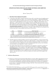
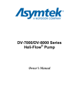
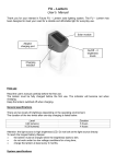
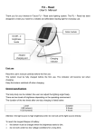
PV GAP
RECOMMENDED
SPECIFICATION
PVRS 11A
2005-03
Amendment 1, 2009-12
Portable solar photovoltaic (PV) lanterns–
Design qualification and type approval
Amendment 1, Extension to include
lanterns with nickel-metal hydride
batteries
Reference number
PVRS 11A : 2004
Amendment 1:2009
Page 0 of 35
PV GAP
RECOMMENDED
SPECIFICATION
PVRS 11A
2005-03
Amendment 1, 2009-12
Portable solar photovoltaic (PV) lanterns–
Design qualification and type approval
(reproduced by kind permission of the World Bank/UNDP
Energy Sector Management Programme (ESMAP),
whose support in the preparation of this publication is
acknowledged by PV GAP)
Amendment 1, Extension to include lanterns with
nickel-metal hydride batteries
©PV GAP 2009
Copyright - all rights reserved
No part of this publication may be reproduced or utilised in any form or by any means, electronic or mechanical, including
photocopying and microfilm, without permission in writing from the publisher.
PV GAP Secretariat c/o IEC Central Office
3 rue de Varembé - PO Box 131 - 1211 Geneva 20 – Switzerland
Fax: 41 22 919 03 00
PRICE
Page 1 of 35
USD 20
PVRS 11A © PV GAP : 2005. Amendment 1, 2009
CONTENTS
Foreword...............................................................................................................................................
3
1 Scope…………………………………………………………………………………………………………
4
2 Purpose ...........................................................................................................................................
4
3 Normative and informative references.............................................................................................
5
4 Abbreviations ...................................................................................................................................
5
5 Testing methods ..............................................................................................................................
6
6 Marking ............................................................................................................................................
10
7 Pass criteria .....................................................................................................................................
10
8 Manual .............................................................................................................................................
13
9 Major defects ..................................................................................................................................
13
10 Load specification ............................................................................................................................
13
11 Solar PV module test………………………………………………………………………………………..
14
12 Switching and solar module connector durability………………………………………………………..
14
13 Protection against open-circuit, short-circuit and reverse polarity tests……………………………….
15
14 Shipping vibration test………………………………………………………………………………………..
16
15 Solar lantern performance tests…………………………………………………………………………….
16
16 Solar lantern testing sequence……………………………………………………………………………….
19
17 Determination of the system balance point………………………………………………………….
….…. 22
18 Indoor testing using a PV module simulator……………………………………………………………………23
19 Modifications…………………………………………………………………………………………………….
24
20 Report…………………………………………………………………………………………………………..
24
Annex A (Normative) Classification of Irradiation and Systems……………………………………………….
25
Annex B (Normative) Instrumentation and Equipment for the System Test………………………………….. 26
Annex C (Normative) Determination of the module output for indoor testing using a PV module simulator…28
Annex D (Informative) Design Recommendations……………………………………………………………….. 33
Annex E (Normative) Declaration of compliance – PV modue……………………………………………………34
Annex F (Normative) Declaration of compliance – Battery………………………………………………………..35
Page 2 of 35
PVRS 11A © PV GAP : 2005. Amendment 1, 2009
FOREWORD
1)
PV GAP (Global Approval Program for Photovoltaics) is a not-for-profit international organization,
dedicated to the sustained growth of global photovoltaics (PV) markets to meet energy needs world-wide in
an environmentally sound manner. Its mission is to promote and encourage the use of internationally
accepted standards, quality management processes and organizational training in the design, fabrication,
installation, sales and services of PV systems. To this end, it partners with PV related industries,
international organizations, testing laboratories, government agencies, financing institutions, nongovernmental organizations, and private foundations, in developing and developed countries.
2)
PV GAP co-operates closely with the International Electrotechnical Commission (IEC) in respect of
standardization (principally with IEC Technical Committee N° 82, Solar Photovoltaic Energy Systems) and
certification (with the IEC System for Conformity Testing and Certification of Electrical Equipment and
Components (IECEE)).
PV GAP publishes specifications that have been developed and recommended by experts from the PV
industry and other organizations, to be used as interim, recommended specifications until the
corresponding IEC standards can be completed. The acceptance of these PV GAP “Recommended
Specifications” is voluntary. PV GAP only recommends these specifications but disclaims any liability for
their utilization.
It should be noted that, as soon as a corresponding IEC standard is issued, the PV GAP “Recommended
Specification” is withdrawn. This is announced on the PV GAP website www.pvgap.org, together with
information about the new IEC standard.
3) The present PV GAP Recommended Specification has been endorsed by the PV GAP Technical
Committee, and approved by the PV GAP Executive Board. Members of the Technical Committee and the
Executive Board bodies are listed on the website www.pvgap.org.)
Changes to the first edition 2005 are mainly as follows:
1.
In clause 1, the scope is extended to include lanterns with nickel-metal hydride (NiMH) batteries. The statement on service
environment is deleted, as inappropriate to solar lanterns.
2.
In clause 3, the list of Standards and Specifications is amended and updated.
3.
In clause 5, the limit for small PV modules is raised from 10 W to 20 W to embrace current practice.
4.
Subclause 5.3, the battery is no longer included. In subclause 7.3 the battery is exempted from testing and certification,
being by now a common professional/consumer off-the-shelf item, sealed and maintenance-free. However, certification of
the battery manufacturer to ISO 9001 or equivalent is required, together with a Declaration (new annex F) by the solar
lantern manufacturer that only such batteries are used and that their advertised cyclic endurance is traceable to test data.
5.
Subclause 5.3 and subclause 14.4, it is mentioned that the lantern is packed for shipping before the vibration testing.
6.
Clauses 6 Marking, 8 Manual, and 9 Major defects, originally written for Solar Home Systems, are simplified for solar
lanterns.
7.
In subclause 7.2 the solar lantern manufacturer may make a Declaration (new annex E) concerning the structural similarity
of the solar lantern PV module to already certified larger modules.
8.
Subclause 16.2 and annex D.8 introduce elapsed charging time for NiMH batteries, which inherently have no high voltage
disconnect parameter at low and medium charging rates, and a low voltage disconnect figure of 1,0 V based on IEC 619512.
4) General enquiries about PV GAP may be addressed to the publisher, which is the PV GAP Secretariat, c/o
IEC Central Office, 3 rue de Varembé, Box 31, CH 1211 Geneva 20, Switzerland, E-mail
[email protected], telefax +41 22 919 03 01.
The publisher will be pleased to receive any comments from users of this PV GAP Recommended
Specification. All comments will be acknowledged.
Whilst every effort has been made to ensure the accuracy of the contents of this PV GAP Recommended
Specification, the publisher can accept no responsibility for any errors that may have occurred.
Page 3 of 35
PVRS 11A © PV GAP : 2005. Amendment 1, 2009
PORTABLE SOLAR PHOTOVOLTAIC (PV) LANTERNS –
DESIGN QUALIFICATION AND TYPE APPROVAL. AMENDMENT 1, EXTENSION TO
INCLUDE LANTERNS WITH NICKEL-METAL HYDRIDE BATTERIES
1 Scope
The specifications, test methods and procedures for indoor tests included in this document cover
portable solar photovoltaic (PV) lanterns, which are lighting systems consisting of a lamp, a lead-acid or
nickel-metal hydride (NiMH) battery and electronics, all placed in a suitable housing made of durable
material such as metal or plastic and an integrated or separate PV module. The battery is charged by
electricity generated through the PV module. The lantern is basically a portable lighting device suitable
for indoor lighting. For the purpose of this standard the service environment of the lantern (without the
PV module) can be described as being fully covered by a building or enclosure to protect it from direct
rain, sun, wind-blown dust, fungus, and radiation to the cold night sky, etc, but the building or enclosure
is not conditioned in terms of temperature, humidity or air filtration.
A lighting device, which provides only unidirectional lighting such as typical flashlights, will not be
classified as a solar lantern in the present context.
The focus of the test methods and procedures in this document is on solar lantern performance and
durability evaluation and therefore includes the lantern components.
The results of this test are applicable to the exact components and the entire lantern configuration that
are tested, as noted in the Conformity Assessment Report referred to in the IECEE Conformity
Assessment Certificate (CAC)
The chosen testing condition is intended to represent the majority of climatic zones for which these
solar lanterns are designed.
Note 1:The test procedure is composed to ensure a lifetime expectancy under conditions of normal use and in moderate
climatic conditions of five years and beyond, without major need for maintenance such as change/replacement of modules,
charge controller, lamps or switches. In practice, however, warranties of only one or two years are common.
Note 2: The test logic is similar to that defined in IEC 62124 for Solar Home Systems (SHS). Testing laboratories qualified to
test SHS against IEC 62124 have therefore both test equipment and expertise in performing the tests.
Note 3: For solar lanterns, some of the regular functions of the modern charge controller in other standalone PV systems may
not be available because of the more simple nature of the solar lantern. On the other hand, electronic ballast of the lamp may
already be included in the electronic circuit.
Note 4: The scope of this specification is limited to solar lanterns using lead-acid or NiMH batteries and fluorescent lamps.
(LED modules are under consideration for a future edition).
Note 5: Annex D (Informative) contains design recommendations, which are not normative. However, experience has shown
that many of these design aspects are positively correlated to the solar lantern’s performance.
2 Purpose
The purpose of this specification is to verify design, performance and durability of portable solar PV
lanterns. While some of the individual components must be qualified, the assembled lantern needs
further qualification, to ensure that the components operate properly together as specified by the
lantern manufacturer. The performance test consists of a check of the functionality, the autonomy and
the ability to recover after periods of low state-of-charge of the battery, and hence gives reasonable
assurance that the solar lantern will not fail prematurely.
Page 4 of 35
PVRS 11A © PV GAP : 2005. Amendment 1, 2009
3 Normative and informative references
The documents below that are indicated as being normative contain provisions, which, through
reference in this text, constitute provisions of this International Specification. At the time of publication,
the editions indicated were valid. All normative documents are subject to revision, and parties to
agreements based on this International Specification are encouraged to investigate the possibility of
applying the most recent editions of the normative documents indicated below. Members of IEC and
ISO maintain registers of currently valid International Standards. PV GAP Recommended Specifications
can be obtained from PV GAP. The other documents listed are informative for the purpose of the
present Specification.
IEC 60068-2-6: 1995, Environmental testing – Part 2 : Tests – Test Fc: Vibration (sinusoidal) Normative
IEC 60529: 1989, Degrees of protection provided by enclosures (IP Code) Normative
IEC 60904-1: 2006, Photovoltaic devices. Part 1: Measurement of photovoltaic current-voltage
characteristics Normative
IEC 60904-2: 2007, Photovoltaic devices. Part 2: Requirements for reference solar devices
IEC 60904-5 :1993, Photovoltaic devices. Part 5: Determination of the equivalent cell temperature
(ECT) of photovoltaic (PV) devices by the open-circuit voltage method Normative
IEC 60904-9: 2007, Photovoltaic devices - Part 9: Solar simulator performance requirements Normative
IEC 61215: 2005, Crystalline silicon terrestrial photovoltaic (PV) modules – Design qualification and
type approval Normative
IEC 61646: 2008, Thin-film silicon terrestrial photovoltaic (PV) modules – Design qualification and type
approval Normative
IEC 61853, Performance testing and energy rating of terrestrial photovoltaic (PV) modules (under
consideration in IEC TC 82)
IEC 61951-2: 2003, Secondary cells and batteries containing alkaline and other non-acid electrolyte –
Portable sealed rechargeable single cells – Part 2: Nickel-metal hydride Normative
IEC 62093: 2005, Balance-of-system components for photovoltaic systems – Design Qualification
natural environments
IEC 62124: 2004, Photovoltaic (PV) stand-alone systems - Design Verification Normative
PVRS 7A: 2005, DC supplied lighting systems with fluorescent lamps for photovoltaic (PV) stand-alone systems
Normative
ISO 9001:2000, Quality management systems – General requirements Normative
4 Abbreviations
AC: alternating current
Ah: Ampere-hours
CAC: Conformity Assessment Certificate issued under the IEC System for Conformity Testing and
Certification of Electrotechnical Equipment and Components (IECEE) and referring to the associated
Conformity Assessment Report and the relevant Standards and Specifications
CFL: compact fluorescent lamp
DC: direct current
Page 5 of 35
PVRS 11A © PV GAP : 2005. Amendment 1, 2009
DRT: daily run time (of the solar lantern)
FS: full screen
HVD: high voltage disconnect (of the charge controller)
IEC: International Electrotechnical Commission (www.iec.ch)
IECEE: IEC System for Conformity Testing and Certification of Electrotechnical Equipment and
Components (www.iecee.org)
ISO: International Organization for Standardization (www.iso.org)
LCD: liquid crystal display
LED: light emitting diode
LVD: low voltage disconnect (of the charge controller)
NCB: National Certification Body
NOCT: Nominal Operating Cell Temperature
NiMH: nickel-metal hydride
PV: solar photovoltaic(s)
PV GAP: Global Approval Program for Photovoltaics
STC: Standard Testing Conditions (reference testing value of cell temperature (25°C), in-plane
irradiance (1000 W/m²), air mass solar reference spectrum (AM = 1,5) for PV module or PV cell
electrical performance testing)
UBC: usable battery capacity
VI: visual inspection
5 Testing methods
The tests in this specification are performed for conditions of irradiance and temperature that cover a
large part of the world where these solar lanterns are being used. However these tests can be adapted
to meet other specific climatic conditions, if those are significantly different from the testing conditions
in this specification.
This solar lantern qualification procedure is based on two series of tests:
•
to test some of the solar lantern components such as the PV module, the lamp, the manual on-off
switch, the module connecting device, the charge controller, and
•
to test the solar lantern as the entire unit.
The first series of tests are component tests, to determine whether the components mentioned above
are appropriate for use in a solar lantern application. The second test procedure then is a type
approval, to verify whether or not the component configuration in the solar lantern is well optimised to
provide the lighting services for which the solar lantern is specified.
These two tests are independent and essential steps for evaluating the quality of solar lanterns. Any of
the components previously tested according to the procedure in this specification and already certified
do not need retesting.
The fluorescent lamps test (PVRS 7A) has been developed under the leadership of PV GAP and is
available through PV GAP:.
Usually, solar lanterns powered by modules having a maximum STC power output less than 20 W can
be subjected to a reduced test sequence, which is based on IEC 61215 and IEC 61646 respectively,
described in clause 11 of this specification. However, if these modules are from a family of modules,
which has a CAC or NCB Certificate to IEC 61215 or 61646, this small module is considered to be
certified for the solar lantern application without any further tests.
Page 6 of 35
PVRS 11A © PV GAP : 2005. Amendment 1, 2009
5.1 Sampling
Three complete solar lanterns for qualification testing (plus spares as specified by the supplier) shall be
taken at random from a production batch or batches. The solar lanterns shall have been manufactured
from specified materials and components in accordance with the relevant drawings and process sheets
and have been subjected to the manufacturer’s normal inspection, quality control and production
acceptance procedures. The solar lanterns shall be complete in every detail and shall be accompanied
by the manufacturer’s handling, mounting and connecting instructions, including safety instructions.
A copy of the CAC or NCB Certificate for the PV-module and relevant test certificate for the lamp(s)
shall be included, if present. Otherwise these tests must be performed independently.
When the solar lanterns to be tested are prototypes of a new design and not from production, this fact
shall be noted in the test report (clause 20). In this case, CACs and certificates will not be eligible for
type approval certification.
If the lamps are sealed or components are not accessible (potted) and the configuration is based on an
inverter/electronic ballast between battery and fluorescent lamps, the solar lantern has to be provided
in a non-sealed/potted version, with the components accessible for measuring current/voltage
characteristics to perform the tests. If DC CFL units with integrated inverter are used, this is not
necessary, even when the lantern is potted. The lamp current will then be measured with an interface
between lamp socket and lamp.
If the solar lantern is designed for different lamps with different run times for each lamp, the
configuration with the largest power consumption shall by default be tested. The manufacturer may,
however, deviate from this procedure and select the configuration for which he wants to get the
certification.
5.2 Testing sequence
In carrying out the tests, the test operator shall strictly follow the manufacturer’s handling, mounting
and connection instructions.
First, two of each of the components shall be subjected to the test sequences in this specification,
carried out in the order laid down. If both components fail any test, the design shall be deemed not to
have met the qualification requirements. If one of the two components fails any test, the third
component shall be subjected to the whole of the relevant test sequence from the beginning. If this
component also fails, the design shall be deemed not to have met the qualification requirements.
Once all the components have passed the component tests, the solar lanterns shall be subjected to the
shipping vibration test and the lantern performance test. The procedures of the lantern performance
test are subdivided into three different tests: the functional test, the autonomy test and the recovery
test.
The lantern shall be subjected to the test sequences in this specification, carried out in the order
described.
If both lantern samples fail any test, the design shall be deemed not to have met the qualification
requirements. If one of the two lantern samples fails any test, the third lantern shall be subjected to the
entire relevant test sequence from the beginning. If this lantern also fails, the design shall be deemed
not to have met the qualification requirements.
Figure 1 represents the qualification process.
Page 7 of 35
PVRS 11A © PV GAP : 2005. Amendment 1, 2009
Sampling
Check for completeness,
certificates etc.
For each component
Certificate?
Yes
No
Test of components
Pass/Fail
Fail
Pass
Test on system
Performance
characteristics
Pass/Fail
Figure 1. Flow diagram representing the qualification process
5.3 Testing levels and criteria
The following table contains an overview over the tests, testing conditions and criteria.
Test
Conditions
Criteria
PV module
The PV module as specified by the
manufacturer and included in the set
shall have a CAC or NCB Certificate
(constitutes acceptability).
IEC 61215, or IEC 61646.
PV module
The PV module does not have a
CAC or NCB Certificate but the
criteria to the right are met
(constitutes acceptability).
Module is identical regarding material used,
production process and production site, to modules
for which the manufacturer holds certification,
except the power output is lower than 20 W
PV module
The PV module does not have a
CAC or NCB Certificate, the module
power is lower than 20 W and the
manufacturer does not manufacture
certified
modules
of
otherwise
identical type.
A standard module test is passed, limited to
Certificate
required
acceptability)
PVRS 7A or equivalent national standards
Lamp
(constitutes
•
•
•
Page 8 of 35
Outdoor exposure test
Damp-heat test, and
Robustness of terminations test.
PVRS 11A © PV GAP : 2005. Amendment 1, 2009
•
Functionality and safety evaluated
•
Resistance of connector <20 mΩ.
Switching and PV module
connector durability test
1 000 cycles.
Open circuit test of the
ballast
Input voltage 1,2 times the nominal
battery voltage, repeat twice.
The lantern shall function.
Open circuit test of the
charge controller
Remove the battery. Apply 1,25
times open-circuit voltage to the PV
module input terminals of the charge
controller.
The charge controller must withstand the condition
without any damage.
Reverse polarity of the
PV module
Apply a reverse polarity voltage
equal to 1,5 times the nominal opencircuit voltage of the PV module to
the PV module input terminals of the
charge controller.
The charge controller must withstand the condition
without any damage.
Reverse polarity of the
battery
Apply a reverse polarity voltage
equal to 1,2 times the nominal
battery voltage to the battery input
terminals of the charge controller.
The charge controller must withstand the condition
without any damage.
Fuses
The battery shall be protected
against short-circuit by (a) fuse(s),
as close as possible to the battery
terminal(s).
Overcurrent devices shall be rated for at least
156% of the short circuit current (at STC) and shall
have a voltage rating of at least 125% Voc.
Shipping vibration test
10 Hz to 150 Hz
Amplitude: 3,5 mm, acceleration: 2 g
1 octave/min, Duration on each axis:
2 h; overall: 6 h. Lantern packed for
shipping before the vibration testing.
The lantern shall function.
System
tests
The functional test, the autonomy
test and the recovery test.
performance
1.
The lamp must function at all stages of the test
unless the charge controller has disconnected the
lamp due to a low battery state of charge (LVD).
2.
The battery capacity shall not decrease over the
testing period more than 10%, expressed by (C0C2)/C0 < 10%; Co is the initial battery capacity and
C2 is the final battery capacity.
3.
Recovery: The ‘recovery test’ should exhibit an
upward trend in the system voltage. During the
recovery test, the total net Ah into the battery
should be >=50% of C1 where C1 is the battery
capacity after recovery test.
4.
After capacity test C1, the load shall begin
operating again on or before the third ‘recovery
test’ cycle.
5.
The System Balance Point (see System
Characterisation Plot) shall match the defined
minimum irradiation class or be below.
6.
The measured days of autonomy shall match the
defined minimum days of autonomy as indicated
by the manufacturer or be above.
7.
The lamp shall operate undamaged according to
the manufacturer’s specification at the maximum
battery voltage occurring during periods of high
irradiance and at high state of charge.
8. No sample shall exhibit any abnormal open-circuit
or short-circuit during the tests.
Page 9 of 35
PVRS 11A © PV GAP : 2005. Amendment 1, 2009
6 Marking
The manufacturer shall provide the solar lantern and the PV module (if not integrated) with the following
clear and indelible markings:
• name, monogram or symbol of the manufacturer/supplier;
• type or model number;
• nominal module and battery voltage;
• serial or batch number;
• polarity of terminals or leads;
• precautionary warning concerning special requirements for storage, putting into service and
handling.
Labelling on equipment shall be in accordance with good ergonomic principles so that warning notices,
controls, indications, testing facilities, fuses etc., are sensibly placed and logically grouped to facilitate
correct and unambiguous identification.
7
Pass criteria
A solar lantern design shall be judged to have passed the qualification test, if each test sample meets
all the following criteria:
7.1 Solar lantern completeness
The lantern shall be complete and contain the following elements:
•
all the necessary hardware;
•
specification by the manufacturer of daily run time (DRT) under testing conditions. For the purpose
of this test, DRT is based on the irradiation class III, as shown in annex A;
•
specification by the manufacturer concerning the design load (Wh), the irradiation level for which
this design load can be energized by the solar lantern, the autonomy and the classification under
design conditions (see annex A). These specifications enable the testing laboratory to verify the
manufacturer’s calculations;
•
specification by the manufacturer concerning the days of autonomy under testing conditions;
•
certificates;
•
manual, as described in clause 8.
7.2 The PV module
The PV module as specified by the manufacturer and included in the set shall have a CAC or NCB
Certificate to IEC 61215 in case of crystalline silicon PV modules and IEC 61646 in case of thin film PV
modules.
In case the module does not have a CAC or NCB Certificate, the following three requirements shall be
met:
(i)
the module manufacturer already has a CAC or NCB Certificate for larger module(s), and
(ii)
the module for the solar lantern application is less than 20 W total power, and
Page 10 of 35
PVRS 11A © PV GAP : 2005. Amendment 1, 2009
(iii)
the module for the solar lantern applies the same materials (including but not limited to solar
cells, interconnecting material, encapsulants, junction box connections) and is made in the
same factory using the same manufacturing installation as for the module(s) for which the
manufacturer has received the CAC or NCB Certificate. The solar lantern manufacturer shall
make a formal declaration in writing to this effect (model declaration in annex E), if the CAC or
NCB Certificate does not mention the solar lantern module.
In case the module does not have a CAC or NCB Certificate and one or more of the above three criteria
do not apply, the module shall be qualified for solar lantern application following the tests described in
clause 11.
Note: The reason for simplifying some of the requirements for modules of solar lantern is based on the following:
Solar lanterns are designed for a minimal lifetime of five years or less (warranties of only one or two years are common), and normally
their price tag reflects the lower life expectancy compared to larger systems. In view of the different lifetime expectation and the smaller
sizes, it is justified to reduce some of the severe tests of IEC 61215 and IEC 61646 respectively. Therefore the retesting of the module is
unnecessary if the module manufacturer already has in the same module family larger modules certified under the IECEE or under an
NCB’s own certification program.
7.3 The battery
The battery as specified by the solar lantern manufacturer and included in the set is exempted from
testing and certification requirements, except that the battery manufacturer shall hold current
certification to ISO 9001 for the site(s) at which the battery (for NiMH batteries, the single NiMH cells)
are manufactured, issued by an accredited certification body or registrar. The solar lantern
manufacturer shall make a formal declaration in writing (model declaration in annex F) that only such
batteries are used, and provide a copy of the ISO 9001 or equivalent certificate and (for lead-acid
batteries) the data sheet that includes cylclic endurance at various depths of discharge and is traceable
to the battery manufacturer’s test data obtained in-house or from an independent testing laboratory.
7.4 The lamp(s)
The lamp(s) as specified by the manufacturer and included in the set shall have a type approval
certificate from an internationally recognised PV quality system. The lamp(s) shall be certified
according to PVRS 7A or to an equivalent national standard.
7.5 Protection against open-circuit, short-circuit and reverse polarity
The inverter shall be protected against damage from voltage under open-circuit conditions (for
example, when the lamp is removed or has failed).
The charge controller shall be protected against damage from voltage under open-circuit conditions
when the battery is removed or has failed and from short-circuit conditions when the PV module
terminals are short-circuited.
The charge controller shall be protected against damage from reverse polarity conditions of battery and
PV module.
7.6 Fuses and circuit breakers
The battery shall be protected against short-circuit by (a) fuse(s), as close as possible to the battery
terminal(s).
Soldered fuses on the printed circuit board are also allowed. Where fuses of different capacity are
installed, they shall have clear colour coding or labelling or be of different physical size.
Page 11 of 35
PVRS 11A © PV GAP : 2005. Amendment 1, 2009
Fuses shall
•
be sized per the conductor size and per the component they are protecting as specified by the
manufacturer,
•
be marked with rated current, voltage and use (AC or DC),
•
be rated for DC service in DC applications, and
•
have appropriate voltage ratings for the circuit they are protecting.
Overcurrent devices protecting PV source and output circuits and carrying currents from the PV modules
shall be rated for at least 156% of the short circuit current (at STC) and shall have a voltage rating of at
least 125% Voc.
7.7 Switch and module connectors
Switches suitable for DC use are to be provided on the lantern. The switch shall be able to withstand a
minimum of 1 000 cycles under load.
The PV module connector shall be able to withstand a minimum of 1 000 connections cycles.
A test sequence is provided in clause 12.
7.8 System performance tests
The solar lantern shall pass the system performance tests described in clause 15
The following pass-fail-criteria apply:
1. The lamp must function at all stages of the test unless the charge controller has disconnected the lamp due
to a low battery state of charge (LVD).
2. The battery capacity shall not decrease over the testing period more than 10%, expressed by (C0-C2)/C0 <
10%; Co is the initial battery capacity and C2 is the final battery capacity.
3. Recovery: the ‘recovery test’ should exhibit an upward trend in the system voltage. During the recovery test,
the total net Ah into the battery should be >=50% of C1 where, C1 is the battery capacity after recovery test.
4. After capacity test C1, the load shall begin operating again on or before the third ‘recovery test’ cycle.
5. The System Balance Point (see System Characterisation Plot) shall match or not exceed the defined
minimum irradiation class.
6. The measured days of autonomy shall match or exceed the defined minimum days of autonomy as
indicated by the manufacturer.
7. The lamp shall operate undamaged according to the manufacturer’s specification at the maximum battery
voltage occurring during periods of high irradiance and at high state of charge.
8. No sample shall exhibit any abnormal open-circuit or short-circuit during the tests.
7.9 Visual evidence of a major defect
There shall be no visual evidence of a major defect, as defined in clause 9, both before and after the
components tests as well as the system performance test as described in clause 15.
Page 12 of 35
PVRS 11A © PV GAP : 2005. Amendment 1, 2009
8 Manual
It is recommended that the manual be written in English and the user’s language and include
•
a complete list of the solar lantern’s external mechanical and electrical components and
spare/replaceable parts,
•
battery safety requirements including replacement procedures,
•
lamp maintenance/replacement procedures,
•
installation instructions that ensure proper placement of the PV module,
•
procedures for proper operation, including load conservation during periods of inclement weather,
and/or a low voltage disconnect event. A checklist that contains what to do in case of a solar lantern
failure shall be included. The procedures for checking that the PV module is not shaded and how to
prevent shading must be explained,
•
maintenance items, and
Instead of a written user’s manual, illustrations may be used where appropriate.
Lantern performance should be specified in
•
rated average energy supply (Wh/day),
•
autonomy (days without sunshine the lantern can service the load), and
•
hours of use of lamp.
The above recommendations may be revised, and in some cases made mandatory, in the light of
practical experience.
9 Major defects
For the purpose of design qualification, the following are considered to be major defects:
•
failure of any solar lantern component;
•
browning of any printed circuit board;
•
loss of mechanical integrity, to the extent that the operation of the solar lantern would be impaired;
•
deterioration of wiring insulation;
•
electrolyte leakage from the batteries;
•
signs of overheating or corrosion.
10 Load specification
Many solar lanterns have multiple lighting modes, e.g. by incorporating two lamps or by electronic
controls.
For the purpose of this test the lamp shall be operated at maximum power.
The manufacturer shall specify the daily number of hours the system can service the load under the
test conditions described in this specification (DRT). This number shall be derived using the irradiation
class III, specified in Annex A.
Page 13 of 35
PVRS 11A © PV GAP : 2005. Amendment 1, 2009
For the purpose of the test and while the PV modules are connected, the load is never operated during
daylight or at times when the solar irradiance is above 50 W/m².
11 Solar PV module test
The purpose of this test sequence is to determine the electrical characteristics of the module and to
show, as far as possible within reasonable constraints of cost and time, that the module is capable of
matching the expected lifetime, which a solar lantern is expected to have.
The test is a simplified version of the IEC module test according to IEC 61215 in case of crystalline
silicon PV modules and according to IEC 61646 in case of thin-film PV modules.
For the purpose of this standard the testing procedure under clause 10 of IEC 61215 or IEC 61646 is
limited to the following three tests:
•
•
•
outdoor exposure test ;
damp-heat test ;
robustness of terminations test.
12 Switching and PV module connector durability test
12.1 Purpose
The purpose of this test is to ensure that the used switch and PV module connector are able to
withstand normal use and do not fail prematurely.
12.2 Procedure
Subject the switch to an initial electrical resistance measurement test. In case the switch has a resistance of
more than 20mΩ, the switch has failed the test.
Make sure the lantern is fully charged and ready for use.
(a) Switch on the lamp; in case there is more than one switch, use all the switches.
(b) Switch off the lamp.
(c) Connect the PV module to the lantern housing.
(d) Flex the module cable at the connector and disconnect the module from the lantern.
Repeat the procedure 1 000 times.
Measure the electrical resistance over the module connection.
12.3 Requirements
None of the components must show signs of wear that endanger the functionality or cause potential
safety hazards.
The switch must function and the module connector shall not exhibit an electrical resistance value more
than 20 mΩ.
Page 14 of 35
PVRS 11A © PV GAP : 2005. Amendment 1, 2009
13 Protection against open-circuit, short-circuit and reverse polarity tests
13.1 Open-circuit test of the ballast
13.1.1 Procedure
A. Connect the lamp with the electronic ballast to a regulated power supply. Adjust the input voltage to
1,2 times the nominal battery voltage. Remove the lamp, switch on/off twice, leave the set-up for 1 hour
and put the lamp back. Wait at least 1 minute. Repeat this test twice without waiting for 1 hour.
Requirement: the lantern shall function.
B. Connect the electronic ballast to the regulated power supply. Do not connect the lamp. Adjust the
input voltage to 1,2 times the nominal battery voltage, wait at least 1 minute and measure the input
current.
Requirement: The ballast shall function properly. This is normally the case when the input current is
not more than 10 mA.
Note 1: Not all lanterns incorporate electronically controlled ballasts.
13.2 Open-circuit test of the charge controller
13.2.1 Procedure
Apply a voltage equal to 1,25 times the open-circuit voltage of the PV module to the PV module input
terminals of the charge controller using a regulated power supply. Remove the battery. Wait at least 1
minute.
Requirement: the charge controller must withstand the condition without any damage..In case of
removing the battery, the PV voltage must not “snap through” to the load terminals! Otherwise the load
can be destroyed. This means, the charge controller must shut down the PV-voltage in case of a
removed battery.
13.3 Reverse polarity test of the charge controller
13.3.1 Procedure for reverse polarity of PV module
Apply a voltage equal to 1,5 times the nominal open-circuit voltage of the PV module to the PV module
input terminals of the charge controller using a regulated power supply connected with reverse polarity.
Wait at least 1 minute.
Requirement: the charge controller must withstand the condition without any damage.
13.3.2 Procedure for reverse polarity of battery
Apply a voltage equal to 1,2 times the nominal battery voltage to the battery input terminals of the
charge controller using a regulated power supply connected with reverse polarity. Wait at least 1
minute. Observe any irregularities (excessive heat, smoke, fire, damaged components, etc) with the
charge controller.
Requirement: the charge controller must withstand the condition without any damage.
Note: battery protection fuses may blow, which is a normal situation and does not lead to failure of this
test.
Page 15 of 35
PVRS 11A © PV GAP : 2005. Amendment 1, 2009
14 Shipping vibration test
14.1 Purpose
The purpose of this test is to identify mechanical weak points and/or to ascertain any deterioration of
the specified performance. According to IEC 60068-2-6, it must be conducted on structural elements or
devices, which are exposed to harmonic vibrations during shipment, such as occur on ships, in aircraft
and land vehicles.
14.2 Requirements
Frequency range:
10 Hz to 150 Hz
Constant amplitude:
3,5 mm
Constant acceleration:
2g
Cycling:
1 octave/min
Duration on each axis:
2h
Total test duration:
6h
14.3 Apparatus
See IEC 60068-2-6.
14.4 Procedure
See IEC 60068-2-6.
The specimens are packed for shipping and not energised during the test.
15 Solar lantern performance tests
15.1 Instrumentation and Equipment
Annex B contains a description of the instrumentation and equipment for the solar lantern tests.
15.2 Test documentation
In addition to recording all the relevant system data, the test operator shall keep relevant test data,
calculations, and appropriate comments. An electronic copy of the system data shall be kept for future
reference.
15.3 Installation
Operate the solar lantern according to the manufacturer’s instructions.
For indoor testing, a 'class C’, or better, solar simulator, as defined in IEC 60904-9, shall be used.
15.3.1 Solar lantern preconditioning
Follow the manufacturer’s instructions for preconditioning the battery for system operation.
In the case of a lead-acid battery, if battery preconditioning is not called for in the solar lantern
documentation, the battery shall be subjected to:
•
at least five cycles from HVD to LVD in an outdoor test or at least five cycles at C 10 for an
indoor test.
Page 16 of 35
PVRS 11A © PV GAP : 2005. Amendment 1, 2009
NOTE: Certain advanced charge controllers need a few days/cycles to find the optimum settings matching the
system design. The manufacturer shall state this and the performance test shall be preceded by the prescribed
number of cycles.
PV modules exhibiting light-induced degradation (e.g. amorphous silicon) shall be subjected to initial
light soaking according to IEC 61646.
15.3.2 Verify load operation
The lamp is an integral part of the solar lantern and the size of the lamp is an important design
parameter. Lanterns may contain more than one lamp or can be varied in brightness. For the purpose
of this test, always the maximum light output as specified by the manufacturer shall be used.
Verify that the lamp starts and operates properly.
In systems with multiple lamps, verify that each individual lamp can start and run while all other lamps
are operating.
For this test, it is only necessary to operate the lamp(s) long enough to determine whether they function
correctly.
Turn off all lamps after verifying they operate properly.
15.3.3 Data acquisition system installation
Install the plane of module irradiance sensor (reference device). The irradiance sensor shall be as
close as possible to the PV module without shading the module and shall be mounted in the same
plane and within +/- 5° of the module tilt angle.
Program the data acquisition system to monitor the measurement parameters and store as 5-minute
averages.
Install the temperature sensors:
•
The ambient temperature sensor must be mounted in an aspirated or double shaded shield.
•
The temperature sensor on the back of the module must be mounted in the middle of a solar cell
within the centre of a module, utilising thermal paste and covering the sensor with insulation
material and foil.
The battery temperature sensor must be mounted as close as possible to the temperature
compensation sensor. If temperature compensation is internal to the charge controller, a temperature
sensor in addition to the battery temperature sensor shall be mounted to sense the controller
temperature.
Install voltage sensors for the PV module and loads.
Install the voltage sensor for the battery at the battery terminals.
Maximum and minimum values of the signals specified in Table shall also be collected and stored.
Install current sensors for the PV module, battery and lamp.
Calculate module and load DC Power. DC power may be computed by multiplying average DC voltage
and average DC current.
Install a sensor to detect proper load operation, for example a light sensor in front of a lamp.
NOTE: In case of a fluorescent lamp, it would not be adequate to only look at the current load as an indicator of load
operation as the lamp could malfunction yet the ballast may continue to draw current.
Note the load operation method.
Modify a copy of the schematic to show the data acquisition system sensor locations.
This modified schematic shall be included in the report of clause 20.
15.3.4 Lantern photographs
Photograph the lantern after the lantern has been instrumented. Include the photos with the
documentation.
Page 17 of 35
PVRS 11A © PV GAP : 2005. Amendment 1, 2009
15.4 Visual inspection
The lantern and its components must be checked for damage and workmanship (for example, suitability
of structural elements)
After each test, flex all conductors along their entire length, noting any discoloration or brittleness of the
insulation. Undersized conductors and poor connections will tend to overheat, leading to brittle and
discoloured insulation.
Any peculiarities observed must be carefully documented in the report (clause 20) and if necessary by
means of photography.
Verify that all parts listed on the parts list are present. Note any missing system parts that should have been
included. If essential parts, i.e. parts without which the system cannot go through the testing procedure, are
missing, the system fails the test and shall be sent back to the manufacturer.
15.5 Test sequences
The following graph indicates the different steps of the system performance test, as described in more
detail in clause 16:
B attery V o ltage
U BC 0
P V on
L oad O ff
V reg
BC
FT
P V on
P V off
L oad O ff
L oad O n
contin uou sly
T =12 h rs
U BC 1
P V on
L oad O n
PV on
Lo ad O ff
T<0.5 hr
RT
PV off
Load O n
continuou sly
UBC2
PV on
Lo ad O n (see text)
P V o ff
Lo ad O n
co ntinu ously
T<0.5 hr
LV D
H old at LV D
fo r at least 0.5 hrs
H old at LV D
fo r at least 0.5 hrs
TIM E
V I = V isua l Inspe ction
VI
VI
VI
VI
S am p le Test P ro file for the solar lantern p erform an ce test
Various test sequences are applied during the test to verify performance for low discharge, battery
recovery, functionality operation and ability to reach HVD/full charge under normal operation in sunny
weather, even after having been completely discharged.
UBC 0 = Initial Usable Battery Capacity Test: Initial capacity test – After installing the system, charge
and discharge the battery, measure the usable battery capacity (UBC).
Vreg = voltage level (or other parameter, e.g. elapsed time in the case of NiMH batteries) at which the
controller determines a ‘full battery level’
BC = Battery Charging: Recharge the battery before running the Functional Test.
FT = Functional Test: Run the Functional Test to verify that the system and load operate properly.
Page 18 of 35
PVRS 11A © PV GAP : 2005. Amendment 1, 2009
UBC 1 = First Usable Battery Capacity Test: capacity test and autonomy test – Charge and discharge
the battery. Measure the usable battery capacity. Determine the system autonomy.
RT = Recovery Test: Determine the ability of the PV System to recharge the discharged battery.
UBC 2 = Second Usable Battery Capacity: Final capacity test –Discharge the battery. Measure the
usable battery capacity.
15.6 System characterisation graph
Plot the values found in the tests and construct the system characterisation graph as described in
clause 17.
Determine the System Balance Point.
16 Solar lantern testing sequence
16.1 Solar lantern testing conditions
The temperature of the batteries shall be kept at 27 °C ± 3 °C.
The general ambient temperature during testing shall be within 27 °C ± 3 °C
The test is valid both for using a solar simulator or a solar module simulator. Both shall have the ability to
simulate the Reference Solar Day using the Daily Irradiance Profiles as described in this specification.
The solar simulator shall be Class C or better. However, for days with a high solar irradiation a three-step profile
is allowed. For days with a low solar irradiation, a constant value of the irradiance is allowed. This specification
may be amended to allow the use of non-solar simulators upon the publication of IEC 61853: Performance
testing and energy rating of terrestrial photovoltaic (PV) modules (under consideration in IEC TC 82).
The requirements for the solar module simulator are described in annex C.
16.2 Initial capacity test
Make sure the system has been properly preconditioned in accordance with 15.3.1.
With PV on and load off allow the lantern to charge the battery by imposing at least 700 W/m². Once
the lantern reaches a state of regulation (for NiMH batteries, after the elapsed time stated by the
lantern manufacturer, see annex D.8), keep the lantern at this state for 12 hours. The battery will then
be regarded as charged.
With PV off and load on continuously, allow the lantern to fully discharge the battery. The battery is fully
discharged when it reaches LVD, see annex D.8 . Allow the battery to remain at LVD for 5 hours.
Record the number of Ah discharged from the battery. This is the Initial Usable Battery Capacity
(UBC 0 ).
Perform a visual inspection as described in the section in accordance with 15.4.
16.3 Battery charge cycle
Switch off the light. Set the simulator at 700 W/m² ± 50 W/m². With PV on and load off let the lantern
recharge the battery till it has reached regulation (HVD) (for NiMH batteries, after the elapsed time
Page 19 of 35
PVRS 11A © PV GAP : 2005. Amendment 1, 2009
stated by the lantern manufacturer). Allow the lantern to stay there for a maximum of 0,5 hours. Record
the number of Ah recharged into the battery.
16.4 Lantern functional test
This test verifies the lantern can service the load as intended.
With PV on and light on as specified by the manufacturer in accordance with clause 10, allow the
lantern to operate 'normally' for 10 days.
The following figure gives an overview of the recommended irradiance profiles to be used in the test:
Page 20 of 35
PVRS 11A © PV GAP : 2005. Amendment 1, 2009
Daily Irradiance Profiles for Functional Test, 10 days
Irradiance
1 kWh/m²
1
6 kWh/m²
2
5 kWh/m²
1 kWh/m²
1 kWh/m²
3
4
5
Cycles
Irradiance
Irradiance
(W/m²)
800
5 kWh/m²
5 kWh/m²
5 kWh/m²
6 kWh/m²
6 kWh/m²
6
7
8
9
10
Day with high
solar irradiation
(6 kWh/m² Total)
Day with high
solar irradiation
(5 kWh/m² Total)
Cycles
Day with low
solar irradiation
(1 kWh/m² Total)
700
600
500
400
300
200
100
6 7 8 9 10 11 12 13 14 15 16 17 18 7 8 9 10 11 12 13 14 15 16 17
Time (h)
Page 21 of 35
0
5
PVRS 11A © PV GAP : 2005. Amendment 1, 2009
Table 1: Cycles of the performance test
Cycle #
Cycle 1:
Cycle 2:
Cycle 3:
Cycle 4:
Cycle 5:
Cycle 6:
Cycle 7:
Cycle 8:
Cycle 9:
Cycle 10:
Irradiance profile
Day with low irradiation (1 kWh/m²), operate load
Day with high irradiation (6 kWh/m²), operate load
Day with low irradiation (1 kWh/m²), operate load
Day with low irradiation (1 kWh/m²), operate load
Day with high irradiation (5 kWh/m²), operate load
Day with high irradiation (5 kWh/m²), operate load
Day with high irradiation (5 kWh/m²), operate load
Day with high irradiation (5 kWh/m²), operate load
Day with high irradiation (6 kWh/m²), operate load
Day with high irradiation (6 kWh/m²), operate load
The cycles do not necessarily have to cover 24 hours, since no rest time between operation of the load
and the PV charging is required.
The following irradiation profiles are minimum requirements that must be applied, better (smoother)
profiles leading to a similar daily sum are also allowed:
Day with high solar irradiation (6 kWh/m²day +/- 0.3 kWh/m²)
1 hour at 100 W/m²
3 hours at 500 W/m²
4 hours at 700 W/m²
3 hours at 500 W/m²
1 hour at 100 W/m²
Day with high solar irradiation (5 kWh/m²day +/- 0.3 kWh/m²)
1 hour at 100 W/m²
2 hours at 500 W/m²
4 hours at 700 W/m²
2 hours at 500 W/m²
1 hour at 100 W/m²
Day with low solar irradiation (1 kWh/m²day +/- 0.3 kWh/m²)
5 hours at 200 W/m²
Perform a visual inspection in accordance with 15.4.
16.5 Second capacity test plus autonomy test
Disconnect the load after the functional test. Set the simulator at 700 W/m² ± 50 W/m². With PV on and
light off recharge the battery till it has reached regulation (HVD) (for NiMH batteries, after the elapsed
time stated stated by the lantern manufacturer) and stays there for a maximum of 0,5 hours.
Disconnect the PV module and switch on the lamp. Allow the lantern to discharge the battery until it
reaches LVD.
Determine the lantern autonomy.
Determine the number of Ah discharged from the battery and the total time to discharge. This is the
Second Usable Battery Capacity (UBC 2 ).
Allow the battery to remain at LVD for at least 5 hours but not more than 72 hours.
Page 22 of 35
PVRS 11A © PV GAP : 2005. Amendment 1, 2009
Perform a visual inspection in accordance with 15.4.
16.6 Recovery test
Connect the PV module and switch off the lamp. Operate the solar simulator with an irradiance profile
of a day with high solar irradiation (5 kWh/m²) in accordance with 16.4. Then connect the load as
specified by the manufacturer in accordance with clause 10.
NOTE - The lantern may still have low-voltage protection at this time. If that is the case, disconnect the load again and
operate the solar simulator with an irradiance profile of a day with high solar irradiation (5 kWh/m²) in accordance with
16.4. Then connect the load as specified by the manufacturer in accordance with clause 10.
Once the load comes on, wait until the lantern reaches LVD or the Daily Run Time has passed.
Repeat this test until the lantern has gone through seven recovery test cycles. The lantern has then
been exposed to an overall irradiation of 35 kWh/m². If the lantern reaches HVD (in the case of NiMH
batteries, full charge calculated on the basis of elapsed time, record after how many recovery test
cycles HVD/full charge was reached.
Record at which ‘recovery test cycle’ the load started to operate.
Measure the net Ah into the battery and to the load during seven Recovery Test Cycles.
After these recovery test cycles switch off the lamp (for NiMH batteries allow the voltage to fall to LVD),
set the simulator at 700W/m² ± 50W/m² and wait until the lantern reaches a state of regulation (for
NiMH batteries, completion of the elapsed time stated by the manufacturer for full re-charging). Once
the lantern reaches a state of regulation, keep it at this state for 12 hours. The battery can then be
regarded as fully charged.
Perform a visual inspection in accordance with 15.4.
16.7 Final capacity test
With PV off and light on continuously, allow the lantern to fully discharge the battery. The battery is fully
discharged when it reaches LVD. Allow the battery to remain at LVD for 5 hours. Record the number of
Ah discharged from the battery. This is the Final Usable Battery Capacity (UBC2 ).
16.8 Operation at maximum voltage
Verify the suitability of the light operated at the maximum battery voltage occurring during periods of
high irradiance (between 800 and 1000 W/m²) and at high state of charge. The light shall be operated
for a period of 1 hour under these conditions. The light shall operate undamaged.
Note: there are lanterns on the markets that have a built-in automatic protection mechanism, preventing
simultaneous charging of the battery and use of the lamp. For such lanterns this test cannot be carried
out.
16.9 Visual inspection
Perform a visual inspection in accordance with 15.4.
16.10 Unusual occurrences
Note any unusual occurrences during the test period.
circuits, data acquisition system malfunctions, etc.
These may include unplanned short or open
Page 23 of 35
PVRS 11A © PV GAP : 2005. Amendment 1, 2009
17 Determination of the System Balance Point
The lantern characterisation plot gives a graphical representation of the minimum average irradiation
that the intended location must have for the lantern to function properly.
Sum the Ah into the battery and the irradiation for each day during the functional and recovery tests. Plot the
battery Ah along the Y-axis vs. irradiation along the X-axis.
The data should tend to fall along and in between two lines similar to those shown in example in Figure 2.
A horizontal line is drawn through the point with the minimum value of Ah for days when the charge
controller limits the module current flowing into the battery. A sloped line is drawn through origin and
the point with the highest value on days the controller does not limit the current flowing into the battery
at any time. The System Balance Point is defined by the intersection of these lines.
The System Balance Point can be determined by calculation or by using graphical means.
The system as shown in Figure 2 will, for example, be suitable for locations that have at least 2,5 kWh/m²⋅day
as a yearly average. Therefore the lantern would be qualified for irradiation class I (Annex A) and the specified
daily load profile (Daily Run Time) which must be stated in the final test report and should correspond with the
manufacturer’s lantern performance declaration.
Note: a different load profile results in different characterisation chart.
Daily Charged Ah into The Battery [Ah]
16
14
12
2
10
5
8
6
System Balance Point
6
4
Test Cycle
2
7
9
8
10
1 3
4
0
0
1
2
3
4
5
6
Irradiation [kWh/m² day]
Figure 2. Lantern characterisation chart, charge sequence example with three irradiation profiles and
10 cycles. Discharge: constant load profile.
Page 24 of 35
PVRS 11A © PV GAP : 2005. Amendment 1, 2009
18 Indoor testing using a PV module simulator
18.1 Testing conditions
An electronic power supply simulating the module characteristics shall be used, which has the ability to
simulate the Reference Solar Day in accordance with 16.4.
Annex C describes the calculations leading to current and voltage characteristics simulating the PV
module under conditions prescribed in this specification.
The temperature of the batteries shall be kept at 27°C ± 3°C.
The general ambient temperature during testing shall be within 27°C ± 3°C.
18.2 Initial capacity test
Perform this test in accordance with 16.2.
18.3 Battery charge cycle
Perform this test in accordance with 16.3.
18.4 Lantern functional test
Perform the functional test in accordance with 16.4.
18.5 Second capacity test
Perform this test in accordance with 16.5.
18.6 Recovery test
Perform this test in accordance with 16.6.
18.7 Final capacity test
Perform this test in accordance with 16.7.
18.8 Operation at maximum voltage
Perform this test in accordance with 16.8
18.9 Visual inspection
Perform a visual inspection in accordance with 15.4.
18.10 Unusual occurrences
Note any unusual occurrences during the test period. These may include unplanned short or open
circuits, data acquisition system malfunctions, etc.
19 Modifications
Any change in the design, materials, components or processing of the lantern may require a repetition
of some or all of the qualification tests to maintain design qualification.
Page 25 of 35
PVRS 11A © PV GAP : 2005. Amendment 1, 2009
20 Report
A report of the qualification tests, with measured performance characteristics and details of any failures and
retests, shall be prepared by the testing laboratory. The manufacturer shall keep a copy of this report for
reference purposes.
Page 26 of 35
PVRS 11A © PV GAP : 2005. Amendment 1, 2009
Annex A (Normative)
Classification of Irradiation and Systems
A.1 Determination of the irradiation class and design irradiation
Derive the Yearly Average Daily Horizontal Irradiation and the Irradiation Range from a meteorological
station near the location of intended use.
The Irradiation Range (H range ) is the difference between the Monthly Average Daily Horizontal
Irradiation in the month with the highest irradiation and the Monthly Average Daily Horizontal Irradiation
in the month with the lowest irradiation (in kWh/m²·day)
Table A-1 contains a classification system for locations with different irradiation patterns.
Every location can thus be allocated to an Irradiation Class.
Table A-1: Irradiation Classes
Irradiation Class
Yearly average daily horizontal irradiation [kWh/m²·day]
Range [kWh/m²·day]
I
II
III
IV
V
VI
<4,5 <4,5 4,5-5,5 4,5-5,5 >5,5 >5,5
>1,5 <1,5 >1,5
<1,5 >1,5 <1,5
NOTE - The calculation of the DRT is based on Irradiation class III.
A.2 Rating systems
For a given system at a specific location, the Effective Daily Energy Available to the Load can be calculated.
This will then be expressed as the Effective Daily Energy Available to the Load for a system of make X at
location Y and shall be expressed in Wh. The same system may classify differently in another country, or even
at another location in the same country.
Page 27 of 35
PVRS 11A © PV GAP : 2005. Amendment 1, 2009
Annex B (Normative)
Instrumentation and equipment for the system test.
The following instrumentation and equipment is necessary for conducting the system tests:
•
DC voltage and DC current measuring instruments.
•
DC amp-hour meter or some other means of monitoring.
•
Elapsed time meter or some other means of monitoring.
•
A PV reference device that has been selected and calibrated in accordance with IEC 60904-2 to
match the test modules regarding the spectral response.
•
Suitable instrumentation to check that the reference device and the module are co-planar to within
± 5°
•
Temperature sensors.
•
A means to identify orientation.
•
Automated data acquisition system to facilitate system monitoring during the test.
Data acquisition system specifications
The datalogger shall use at least a 12 bit analog-to-digital converter and have an input range that
exceeds the expected positive and negative maximum voltages. The data acquisition system must be
reliable: if more than 4 hours of data is lost, or if any critical data is lost due to power failure during any
test, then that test shall be restarted.
The sample rate of the datalogger is dependent on the type of charge controller. For ON-OFF
controllers, the datalogger sample rate shall be at least two times faster than the switching period of the
controller. As an example, if the operation of the regulation voltage circuitry is every 10 seconds, then
the sample rate shall be once every 5 seconds, or faster.
For charge controllers using constant-voltage or pulse-width-modulation circuitry, the switching period
may be milliseconds, not seconds. The sampling rate of the datalogger should be at least twice the
switching frequency of the charge controller. If the sample rate of the used datalogger is not fast
enough, then one method is to sample once per second with an integrator/filter circuit added to the data
acquisition system input. The time constant of the integrator/filter will need to be at least two times the
sample period.
An oscilloscope may be required to determine the controller type and its switching frequency.
Data shall be stored as 5 minute averages as appropriate for each test.
The following parameters shall be measured/determined:
Page 28 of 35
PVRS 11A © PV GAP : 2005. Amendment 1, 2009
Table B-1. Parameters to be Measured/Determined
Measured parameter
Recorded Values
Comments
Module voltage
Minimum, average and maximum
Voltage at the module, before blocking
diodes
Load voltage
Minimum, average and maximum
Battery voltage
Minimum, average and maximum
Module current
Minimum, average and maximum
Load current
Minimum, average and maximum
Battery current
Battery amp-hours in and out
Air temperature
Average
Module temperature
Average
Use IEC 60904-5
Battery temperature
average
At temperature compensation sensor or
negative battery terminal
Solar irradiance
Average
Reference device, short circuit current
and temperature of device
Load operation
Load Run Time
Measured at the load
Measured at the battery
Sensor specifications
The voltage sensors shall have a range exceeding the maximum expected voltage and the
measurement shall have a resolution of 0.01 V or better. The current sensors shall have a range
exceeding the expected maximum positive and negative current and the measurements shall have a
resolution of 0.01 A or better.
DC voltage and DC current measuring instruments shall comply with IEC Publication 60904-1, except
that the accuracy shall be within ± 1% FS.
The temperature sensors shall have a range exceeding the expected maximum positive and negative
system and ambient temperatures and measurement resolution of 1 C or better. The temperature
measurement accuracy shall be ±2 C or better.
The irradiance sensor shall have a suitable range and an accuracy of at least ±5% of the reading.
Page 29 of 35
PVRS 11A © PV GAP : 2005. Amendment 1, 2009
Annex C (Normative)
Determination of the module output for the indoor testing using a PV module simulator.
NOTE: Please be aware that certain PV module simulators may not be compatible with all types of charge
controllers due to the internal switching frequencies.
C.1
Constant current source simulation
The following flow diagram explains the steps to be taken to arrive at appropriate settings for a constant current
source simulating the PV module:
Module Data
(STC, NOCT)
Irradiation Profile
Ambient Temperature
Procedure for temperature
and Irradiation Correction
Range of Battery
Voltage
Set of Array IV-Curves
Performance Test
Assuming the NOCT of the module is determined, only the performance of the module under STC shall
be measured (refer to module performance data).
The output corresponding to the conditions at the defined reference solar day has to be calculated
according to following formula:
Page 30 of 35
PVRS 11A © PV GAP : 2005. Amendment 1, 2009
T r an s la tio n fac to rs
⎡
⎤ G2
I SC ,2 = I SC ,1 ⋅ ⎢1 + α ⋅ (T 2 − T1 )⎥ ⋅
⎦ G1
⎣
G2
⎡
⎤
V O C , 2 = V O C ,1 ⋅ ⎢ 1 + a ⋅ ln
+ b ⋅ (T 2 − T1 )⎥
1
G
⎣
⎦
T r an s la tio n e q u a tio n s fo r th e IV d a ta p o in ts
⎛ IS C,2 ⎞
I 2 = I1 ⋅ ⎜
⎟
⎝ ISC,1 ⎠
C urre n t:
V o lta g e:
V 2 = V1 +
(V
OC ,2
)
− V O C ,1 + R S ⋅ ( I 1 − I 2 )
M o d u le p ara m e te rs
: dim e n sio n les s te m p era tu re c oe ffic ie nt o f I S C
: dim e n sio n les s te m p era tu re c oe ffic ie nt o f V O C
α
b
a
RS
: dim e n sio n les s ra dia tion co rre ctio n fac to r o f V
: se ria l re s ista nc e of th e m od u le, P V arra y
(d e fa u lt = 0 .0 0 05 /°C )
(d e fa u lt= -0.0 04 /°C )
(d e fa u lt= 0 .0 6 )
(d e fa u lt= 0 )
OC
Temperature and irradiance correction of current-voltage characteristics
As a result of the procedure for temperature and irradiance correction a set of IV-curves is defined
according to the specified reference solar day. One curve for each step of the day profile is estimated.
This procedure must be repeated for every profile which is used in the test sequence of the
performance test.
7
6
Module current in A
5
4
3
2
1
0
0
2
4
6
8
10
12
14
16
18
20
22
M o d u l e v o lt a g e i n V
T M D p e r fo r m a n c e
S T C p e r fo rm a n c e
L in e o f M P P
Figure C-1: Set of IV characteristics for a daily irradiance profile (example)
The solar lantern voltage is dominated by the battery voltage. Hence the module operates in the range
of the battery voltage. The window is limited by two significant thresholds. The upper limit is the High
Voltage Disconnect (HVD) set-point for lead-acid batteries (fully charged state for NiMH batteries, see
annex D.8) which disconnects the module at a certain voltage (or at full charge for NiMH batteries). The
lower limit is the deep discharge point which protects the battery and cannot be exceeded by normal
system operation.
Page 31 of 35
PVRS 11A © PV GAP : 2005. Amendment 1, 2009
The IV-curves within the window can be estimated linearly. These estimated linear lines are called
operation lines. Each IV curve within the battery voltage range is defined by means of two operation
lines to achieve a good estimation. The operation lines are defined by three points on the IV-curve. The
point of intersection between module IV-curve and the lower voltage limit is the first point (Lx). The
second point (Mx) is at the middle of the defined voltage range. The point of intersection between
module IV-curve and the higher voltage limit is the third point (Hx).
11.1 V
14.6 V
Line of voltage drop
due to ohmic losses
L6
L5
example:
5 m cable 2.5²
resistance = 0.034 Ohms
Voltage drop at 3 A = 0.1 V
L4
L3
M3
L2
Voltage drop
caused by
blocking diode
(approx. 0.7 V)
H3
M2
H2
L1
M1
H1
10
11
12
13
14
15
16
Module voltage
Figure C-2: Approximation of module characteristics by a set of module operation lines
NOTE - The vertical line at 11.1 V is the Low Voltage Disconnect (LVD) and the vertical line at 14.6 V is the High Voltage
Disconnect (HVD) set-point for lead-acid batteries of the charge controller. Different charge controllers, including those for
NiMH batteries, have different set-points.
Page 32 of 35
PVRS 11A © PV GAP : 2005. Amendment 1, 2009
C.2
Module simulation procedure
The electrical behaviour of the module can be simulated by means of a programmable constant current
source.
Charging of the battery is controlled by the processing unit.
Inputs: - current-voltage co-ordinates for the linear approximation of the module
characteristics
- battery voltage
Output: - module current
Depending on the measured battery voltage, the current is changed continuously by successive
approximation steps until the current-voltage operation point fits with the module operation line.
O p e r a t io n
p o in t
C u rr e n t fr o m c o n s ta n t
c u rre n t s o u rc e
I1
A rr a y o p e r a t io n li n e
s p e c if ie d f o r a
P T O C t im e s te p
I2
I3
B a tt e r y v o l t a g e
V3 V2 V1
P T O C - P e r f o rm a n c e T e s t u n d e r
O p e r a t io n C o n d it io n s
Figure C-3: Iteration process for current adjustment
C.3
Set-up for testing
The lantern without module(s) shall be installed in a climatic chamber (in case the charge controller
uses a separate temperature sensor, it is possible to place only the battery in a climatic chamber or a
bath).
Page 33 of 35
PVRS 11A © PV GAP : 2005. Amendment 1, 2009
Figure C-4: Experimental set-up for PV system performance testing
C.4
Algorithm for simulation of the module performance
Initialise source
Isource = IL1
Measurement of
battery voltage VBat
VBat
fits with
operation
line?
yes
no
no
Ii+1 = Ii +
I
yes
VBat > VOL?
Ii+1 = Ii -
I
Adjustment of
source current
ISource = Ii+1
Flow chart for simulation of the module performance presented for one time step of the PTOC
profile
Page 34 of 35
PVRS 11A © PV GAP : 2005. Amendment 1, 2009
Annex D (Informative)
Design Recommendations
The following recommendations represent current best-practice design recommendations for portable solar PV
lanterns.
D.1
Reverse current
Reverse current, that is to say battery discharge into the module(s), should be minimised. The means
by which this is achieved should be documented. If blocking diodes are used, the current capacity
should be 50% higher than the short circuit current (at STC). The peak inverse voltage of the diode
should be at least double the open circuit battery voltage.
D.2
Quiescent current
The quiescent current i.e. the self-consumption when no lamp is lit, should not exceed 2,0 mA.
D.3
Protection against dust, water and foreign bodies (IP-code)
Since the solar lanterns are predominantly used indoors, but may be taken outdoors occasionally and
hence may be subjected to occasional rainfall, a minimum IP class of IP23 (see IEC 60529) is
recommended. This also ensures a desired level of safety with regard to accidental accessibility of live
parts.
D.4
Cable
A water resistant, mechanically robust and UV resistant cable should be used between the solar PV
module and the charge controller. A cable at least 5 m long should be provided for inter-connection
between the module and the lantern
The continuous maximum current rating of the conductors (after any deratings for temperature or
installation conditions) in PV source and output circuits should be at least 156% of the short circuit
current (at STC) and should not be less than the rating of any overcurrent device protecting those
conductors.
All wiring should be colour coded and/or labelled.
D.5
Connectors
All connectors should be polarised and be able to withstand 156% of the short circuit current at STC.
The rated current carrying capacity of the connectors should not be less than the circuit current rating.
D.6
Indicators
The lantern should provide
• an indication of charging state, and
• an indication of load-disconnect state.
The indicator may consist of LEDs or an LCD.
Page 35 of 35
PVRS 11A © PV GAP : 2005. Amendment 1, 2009
D.7
Switching thresholds for charge controllers for lead-acid batteries
The following thresholds are recommended for using the battery voltage as the main parameter for the
switching algorithm, at a surrounding temperature of 20 °C and an acid concentration of 1,24 kg/l:
•
High Voltage Disconnect (HVD):
•
High Voltage Reconnect by two-point regulation (HVR):
•
Low Voltage Disconnect (LVD):
≥ 1,90 V/cell
•
Low Voltage Reconnect (LVR):
≥ 2,15 V/cell
> 2,35 V/cell
2,15-2,35 V/cell
At other acid concentrations, the required thresholds must be adjusted according to the manufacturer's
specifications.
NOTE 1: The lower limit of the Low Voltage Disconnect is an absolute minimum.
NOTE 2: These values are primarily intended for charge controllers that use the battery voltage as the main parameter for the
switching algorithm. Some manufacturers use other parameters, e.g. state of charge.
D.8
Switching thresholds for charge controllers for NiMH batteries
Due to the flat charging characteristic of NiMH batteries used in solar lanterns (typically, low to medium charging rate), there
is no High Voltage Disconnect (HVD) point. Full charge is achieved when at least 150% (or as otherwise stated by the battery
manufacturer) of the battery capacity has been charged into the discharged (LVD 1,0 V) battery. The simplest solar lanterns
may (the word “may” is not intended to be permissive but only to introduce the following observation) not incorporate
discharging to LVD and timed charge termination, relying on the daily daylight “self regulated” system instead. This may result
in some overcharging, which is generally tolerated by the battery but shortens its life.
The Low Voltage Disconnect (LVD) point is 1.0 V/cell (based on IEC 61951-2) unless otherwise specified by the solar lantern
manufacturer. Lanterns that do not posses an LVD feature run the risk of cell destruction in series strings of cells (e.g. five
cells, to provide 6,0 V at full charge) that can arise from forced reverse charging of weak cells as the battery discharges
Annex E (Normative)
Declaration of Compliance – PV module
The Company XY hereby declares that the PV module that is used for all Company’s Solar Lanterns
(hereinafter referred to as “Solar Lantern Module”) under the product name (name of the Solar Lantern) ZZ is
structurally similar to modules which are currently certified to IEC 61215 or IEC 61646 or to a nationally
equivalent standard (hereinafter referred to as “Certified Module”) by an accredited certification body (see Note
below).
“Structurally similar” means that the Solar Lantern Module is produced at the same plant, by the same
processes and from the same materials as the Certified Module.
(The certificate for the Certified Module must be attached to the present Declaration).
CEO name, signature and date
Note: to facilitate the start-up of testing and certification of Solar Lanterns to PVRS 11A Amendment 1, the
above requirement for certification of the “Certified Module” is replaced until December 31 2008 by testing by an
accredited testing laboratory. Test reports to IEC 61215 or IEC 61646 (or only to the three tests, outdoor
exposure, damp heat and robustness of terminations of IEC 61215 and IEC 61646) must be dated 2006 or later
and attached to the present Declaration.
Page 36 of 35
PVRS 11A © PV GAP : 2005. Amendment 1, 2009
Annex F (Normative)
Declaration of Compliance - Battery
The Company XY (hereinafter refered to as “Company xy”) hereby declares that the battery that is used for all
Solar Lanterns (hereinafter referred to as “Solar Lantern Battery”) under the product name (name of the Solar
Lantern) ZZ is produced by a company, be it by Company xy itself or by a third party producer, (hereinafter
referred to as “Production Company”) which currently holds quality management system certification issued by
an accredited certification body or registrar to ISO 9001 or an equivalent standard or specification.
The scope of the above certification must include the site(s)of the Producing Company, at which the Solar
Lantern Batteries are manufactured(for NiMH batteries, where the single cells are manufactured).
(The certificate for the quality management system must be attached to the present Declaration, together (for
lead-acid batteries) with the Production Company’s data sheet that includes cyclic endurance of the lead-acid
battery at various depths of discharge and which is traceable to the battery manufacturer’s test data obtained inhouse or from an independent testing laboratory).
CEO name, signature and date
080212/080305/091231
Page 37 of 35