1
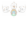
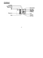
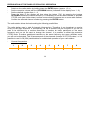
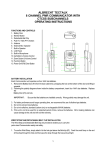
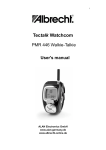
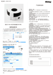
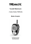
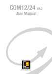
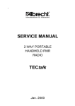
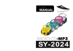
CONTENT
INTRODUCTION
3
APPLICATION AND COMMUNICATION
4
SIZES
6
TECHNICAL DESCRIPTION
8
FUNCTIONS
9
-
Fitting the helmet
Sun shield
Transmission and reception
Socket for external connection
Arial
LCD display
Buttons
Switching between the built in transmitter and external devices
Microphone
Battery – type, replacement instructions
Adjustment of headphones
Upholstery
9
9
9
9
9
10
11
11
11
12
13
13
RADIOSTATION
-
13
user manual
14
TECHNICAL PARAMETERS
26
SERVICE AND MAINTENANCE
27
TRANSPORT AND STORAGE
27
VERSION
28
ACCESSORIES AND FITTINGS
29
WARRANTY
30
2
INTRODUCTION
Congratulations on your decision to purchase this helmet made for motorized flying. This is a top
quality product which was developed with the focus on your safety and maximum comfort during
flying.
The helmet will allow you to communicate during flights with other air traffic participants or with a
flying companion. You can communicate via mobile network operators, listen to music or to the
signalization of the operating values.
All operating controls are designed in such a manner that the pilot will not be restricted in any form
while operating the sports flying equipment (SFE) and therefore will enjoy maximum comfort
during flying.
3
APPLICATION AND COMMUNICATION
Due to the design, the helmet is soundproofed against unwanted outside sound and the active
microphone filter is intended for use when flying motorized, particularly open to the air SFE. The
helmet is not suitable for use for un-motorized flying. The helmet must not be used for skiing,
water sports, motorcycling, cycling or other similar sports.
Do not use the radio when near petrol stations, areas containing explosives or any areas were use
of such equipment is prohibited.
The fully equipped version will allow you to choose between various levels of communication
within the neighbourhood or surroundings:
Integrated radio station on the frequency 446 MHz
When using this radio station, free operation (i.e. without any charge) is allowed including
registration based on the CTC general licence and European regulations valid for the PMR
radio stations The radio station responds to the frequencies of the relevant general CTC and
is classed under the European norms, ETS 300296 and ETS 300279. It has been cleared for
free use in the following European countries: A, B, CH, CZ, D, DK, E, F, FIN, GB, GR, H, HR,
IS, IR, L, NL, P, S, TR
-
An externally connectable transmitter operating on the frequency 118 – 138 MHz.
The only permitted person that can use this transmitter in the air traffic zone is a qualified
owner of an amateur radio licence. The operation of such a radio station must be paid for.
-
Externally connectable mobile phone. Communication via the GSM network of operators
must be paid for.
4
The following equipment can be externally connected to the helmet:
Portable music players (walkman, discman or mp3)
Acoustic flying equipment
Equipment signalling exceeding the limit values (i.e. motor temperature, fuel level,…)
The pilot is fully responsible for the flight course.
Any activity or communication must not be given priority before operating the SFE.
5
SIZES
The correctly chosen size of the helmet means that the helmet will sit tight on the head, does not
uncomfortably press on any part of the head, allows free head turn, backward bending and does
not restrict any sideways view. The headphones should be pressed firmly enough to the ear to
ensure sound proofing against unwanted outside sound.
size
Head circumference
(cm)
Head circumference
(inches)
Hat
S
M
L
56 - 57
58 - 59
60 - 62
22
22 ¾
23 5/8
7
7¼
7½
6
7
TECHNICAL DESCRIPTION
FULL CONTACT 3
1.
2.
3.
4.
5.
6.
7.
8.
9.
10.
11.
12.
13.
14.
15.
16.
17.
18.
19.
20.
21.
Protective shell
Sunshield (multiple position)
PTT Button (broadcasting, keying, ringing to the opposite station)
External connection (external transmitter, telephone, radio, equipment, ...)
Arial (Attention - this cannot be dismantled.)
LCD display
Button UP (regulation of the volume, increasing of selected value up)
Button DOWN (regulation of the volume, decreasing of selected value down)
Button for locking the keyboard
Button for MENU
Button for ringing tone
Button for scanning the channels and monitoring
ON/OFF button
Battery compartment (3xAAA, Li-ION)
Microphone
Headphones including speakers – silent without speakers (adjustable )
Front-end upholstery (removable)
Parietal upholstery (removable)
Back upholstery (removable)
Switch INT / INT-EXT / EXT (inbuilt radio / combination / external tool)
Fasten belt
8
•
•
•
•
•
•
•
•
•
•
•
•
•
•
•
•
•
•
•
•
•
FUNCTIONS
Fitting the helmet
Hold the shell (1) of the helmet on cheek areas, gently stretch it apart and fix it over the ears.
Sun shield
(2) Prevents dazzling. The range of positioning is provided by the end stops. Do not position
the shield beyond the given range. Use the top edge position when starting (by doing it this way,
the shield will not limit your top view). The dazzle stop position is set during the flight.
Broadcasting and reception
To broadcast, the PTT button (3) must be pressed and held down for a short period. This is also
applicable for mobile phone use. When releasing the button, you are receiving. The upper position
of the button will not limit the pilot during operation of the PK.
Socket for external connection
(4) External equipment can be connected and secured by screwing in the outlet nut to ensure that
the cross-connecting cable will not disconnect and fall into the propeller.
Aerial
(5) The aerial cannot be dismantled. Prevent the aerial against breaking during transportation
and storage by using the protective packaging. Do not lift and carry the helmet while holding
the aerial.
9
LCD display (6)
10
Buttons
9-13
Switching between the in-built transmitter and the external equipment
The triple mode button (20) is positioned on the right under the bottom edge of the shell.
The forward position is for external equipment, the middle position for combined use and the back
position is for the built-in transmitter. Switching the modes is possible either on the ground or in
the air during the flight.
In the back position (INT) you are switched in the mode of built-in transmitter. This way you can
communicate with other pilots or ground crew.
In the middle position (INT/EXT) is the external equipment preferred. In case of using PTT button
for transmission, or if anybody uses your set frequency on built-in transmitter, the microprocessor
automatically tunes down the external equipment and receives or transmits from built-in
transmitter. After the relation is ended, the microprocessor slowly returns to external equipment.
In the front position (EXT) is active only the external equipment and its using is not disturbed by
any relations from built-in transmitter. All electronic functions are conditioned by switching on
the built-in transmitter (button 13). Switching on the built-in transmitter is signalized by soft tick.
Diversity microphone
The system of diversity microphone actively restrains the engine noise. The microphone (15) is
positioned on the front part of the flexible neck, which is used to set the correct position. Under the
foam cover there is recognizable flat, which determines the position to the mouth. During the flight
transmission, the microphone should be about 1cm far from the mouth. After pressing the PTT
button, speak slowly and clearly. The flexible neck of the microphone must not be used to lift or
carry the helmet. It cannot be dismantled and has a limited range of movement. The microphone is
permanently fixed on the neck. Do not twist!
11
Batteries – type and replacement
For operating the built-in transmitter is used Li-ION accumulator supplied in helmet set. Charge
the Li-IONA accumulator as soon as possible after use, and never leave it longer time flat in the
helmet. This accumulator is possible to charge by two ways:
a) charging in the second transmitter (supplied in the helmet set) in the charging stand.
b) charging directly in the helmet. Charging stand supplied in the helmet set can be
connected to the helmet by external connector (4). It is possible to charge this way
entirely the Li-ION accumulators supplied in the helmet set. Charging the Li-ION
accumulator should be observed by operator. Pay attention to the right position of the
charging cable, while connecting it to the helmet. During the careless handling there is a
risk of wrong connection.
To ran built-in transmitter it is possible to use 3 AAA batteries as well (in total 4,5 V). These are
placed inside the helmet under removable battery cover (14). It is possible to use alkaline batteries
or NiCd or NiMH accumulators. Change all 3 AAA batteries at a time during the battery change.
Pay attention to correct polarity of single batteries. Low batteries must be changed. Do not leave
them in the helmet. You can check batteries condition on transmitter display (6). Any of these
batteries is not possible to charge neither in the helmet nor in supplied charging stand.
Charging electronics was not developed for this way of use, and this charging could cause
destruction of accumulator or the helmet electronics or possibly fire.
12
Headphone adjustment
(16) The headphones are removable and fully adjustable for the correct ear position. If the correct
adjustments are achieved, the headphones will be comfortable and soundproof against outside
sound. The correct ergonomic position is the narrow side down. It is possible to replace the sides
of the headphones (for this, the 2-pin connectors on the service cable must be reconnected).
Upholstery
The upholstery contains three parts (17 – 19) which are removable in order to allow better
maintenance.
13
PREPARATION OF THE RADIO STATION FOR OPERATION
-
Switch on the radio station by holding down the ENTER button (approx. 1,5 s)
Set the reception volume with the UP/DOWN buttons (indicated on the display from 1 – 8)
Set the channel number from 1 – 8
Press the letter F, the display will then show the letters "CH“, by pressing the buttons
UP/DOWN choose the channel number (it is necessary to set the same channel or possible
CTCSS code (see further down) to allow communication between two or more radio stations.
Confirm the selected channel number by pressing the ENTER button.
The radio station allows the basic setting the following possibilities:
The radio station uses in total 8 channels (frequencies). Therefore, it can broadcast or receive
on any of the eight channels. If, theoretically, all the 8 channels will be occupied or you do not
want to be disturbed by a random discussion of another air traffic participant on the same
frequency and you do not want to change the channel, it is possible to select the protective
CTCSS code. If another participant transmits on the same frequency but uses a different code,
you will not be disturbed. This is because each of the channels contains 38 CTCSS codes, i.e. it is
possible to use 8 x 38 (304) combinations for undisturbed operation of your radio station.
-
Channel frequencies
1
2
3
4
5
6
7
8
446,00625
446,01875
446,03125
446,04375
446,05625
446,06875
446,08125
446,09375
14
-
Setting of the CTCSS code
Press the letter F and locate the CTC symbol. It is switched off in the basic position. By
pressing the UP/DOWN buttons, set the code and confirm by pressing the ENTER button.
The code will now show on the display and will remain in the memory even after switching
the station off. By pressing the ENTER button during the flight, you can check on the display
which code position from (1-38) is being activated. Cancellation can be done by repeating the
sequence, i.e. locate in the menu the CTC symbol and press the UP/DOWN buttons, locate
the – off on the display and press ENTER. The display will now show --recommended setting
– according to the agreement with the remaining air traffic participants.
CTCSS code
1
2
3
4
5
6
7
8
9
10
11
12
13
Sub tuning
frequency
(Hz)
67,0
71,9
74,4
77,0
79,7
82,5
85,4
88,5
91,5
94,8
97,4
100
103,5
CTCSS code
14
15
16
17
18
19
20
21
22
23
24
25
26
15
Sub tuning
frequency
(Hz)
107,2
110,9
114,8
118,8
123,0
127,3
131,8
136,5
141,3
146,2
151,4
156,7
162,2
CTCSS code
27
28
29
30
31
32
33
34
35
36
37
38
Sub tuning
frequency
(Hz)
167,9
173,8
179,9
186,2
192,8
203,5
210,7
218,1
225,7
233,6
241,8
250,3
-
Setting the scanning (searching)
Your station will allocate the channel that your friends use. Press the letter F and locate
on the menu the SC symbol. Use the UP/DOWN button and select the manner that
the searching should start (up or down) then press ENTER. To switch the UP/DOWN
function, locate the “off” and confirm by pressing ENTER. If your station finds an ongoing
communication under the scan mode activation, it will stop searching at this point. If you
do not press the letter F again, it will start searching again after a short period.
Recommended setting – off.
-
Setting the Dual – Watch mode
This mode will allow you to monitor 2 freely selected channels if you expect a message to be
received on at least one of them. This mode can be used, if for example your friends (groups)
talk on different channels and you want to be in touch with both of groups if urgently required.
Select the basic channel in the normal manner and press the letter F then locate in the menu
the dW symbol. Using the UP/DOWN buttons, select another channel which you wish
to monitor. Confirm by pressing ENTER. You can deactivate this mode by pressing the letter
F. The dW can be deactivated by using the UP/DOWN buttons in the dW menu until you
locate "off”, then press ENTER.
Recommended setting – off.
16
-
Setting the VOX mode (voice activation)
This mode is disconnected – cannot be used
Recommended setting – off
-
Setting the lock
While working with the radio station, accidental reprogramming, for example, of the channel
number could be caused. The result is that you will not be able to communicate with another
station in an emergency situation. This is why you can lock an important setting while
the PTT button (broadcasting / reception) will remain functional.
The lock can be activated as follows:
manually - by pressing the F button and hold (for approx. 2 sec), by pressing again,
it will be deactivated.
automatically – locate the AL symbol on the menu and while using the UP/DOWN
buttons set the auto (during the deactivation off). The set modes will be locked
in approximately 15 seconds. If you wish to change any of the modes (for example
the volume or the number of the channel), press the F button for (approximately
2 seconds) and make the change. The lock will be automatically activated after
approximately 15 seconds. This will not allow you to make the mistake of again
forgetting to lock the preset modes.
Recommended setting – on
-
Setting the ring tones
Your radio station will allow calls not only by voice but it can also bring to your attention
the intention for connection via 7 selected ring tones. If you want to ring the other station,
simply press the PTT button twice. To select the ring tone according to your requirement then
17
select in the menu while using the F button, the CAL symbol. Use the UP/DOWN button to
select the ring tone, confirm by pressing ENTER. Recommended setting – OFF!
TECHNICAL PARAMETERS
Weight
Sizes (l x w x h)
Shell
External connection
Frequency range
Frequency separation
channels
Receiver
Sensitivity
VF Output of transmitter
Modulation
Power
Consumption
silence
680 g
link-up
720 g
full contact
850 g (without batteries)
280 x 250 x 250 mm
sandwich design, kevlar, fibreglass laminate
6-pin microphone connection
All 8 frequencies in the PMR 446 MHz band
of 12,5 kHz
Super head with double mixing
(1. MF = 21,7 MHz, 2. MF = 450 kHz)
Greater than –120 dB / 20 dB SINAD
Max. 500 mW ERP
-F3E (FM narrowband),
Push-to-talk operation (only one person can speak)
6V – 4 AAA alkaline batteries
Or accumulators of AAA size
During reception without previous signal, approx.6 mA average
During reception with modulation, approx. 120 mA
During transmitting at full capacity, approx. 300 mA
18
Range
The built in radio station can offer top quality parameters and
sensitivity. The distances the radio stations can function in
between is given by the surroundings. This is why the range is
variable but can normally reach approximately 5 Km and in
some cases even further. In direct and clear visibility, it can
sometimes reach up to tens of kilometres.
FITTINGS AND ACCESSORIES
-
Cross-connecting cable for the music player
Cross-connecting cable for the mobile phone (according to the type)
Cross-connecting cable for the transmitter operating in the mature radio band - 2m
Cross-connecting cable for the transmitter for air traffic frequency
The Albrecht Tectalk 446 MHz transmitter
19
SERVICE
-
Do not use other than the original accessories
Do not leave the helmet unattended in the direct sunlight or dusty or damp areas
Do not try to dismantle or repair the radio station. Service and repair must be provided by the
manufacturer or authorized salesman.
To clean the shell and the sunshield, use water and an ordinary detergent.
The removable parts of the upholstery can be lightly hand washed using lukewarm water. Dry
all parts thoroughly.
Do not soak the headphones! Clean with a damp cloth only.
Switch off the radio station and do not use if water has penetrated.
TRANSPORT AND STORAGE
-
Transport the helmet in the light packaging supplied by the manufacturer in order to protect
the helmet from scratches or dust penetration.
Do not place any heavy object on the helmet during transport or storage.
Store the helmet in a dry, dust-free, temperature-stable and clean environment.
Remove the AAA batteries before long term storage.
20
21
VERSION
Production number
Type
silence
link-up
Sizes
S
M
L
XL
orange
blue
red
yellow
Colour
combinations
22
full contact
WARRANTY
-
-
The warranty covers labour faults and materials for all helmet parts for a 12 month period.
The warranty will be provided under the condition that the buyer (the user) will follow the rules
for correct operation as per the manual which is a part of the product.
Any warranty claim must be supported with a valid warranty certificate which has been
stamped and signed by the seller and the buyer on the day of purchase.
The right to claim will be evaluated by the service technician of the manufacturer.
The warranty will not cover the following:
Damaged caused by outside events
Mechanical damage
Damage caused by unprofessional handling
Damage caused by inappropriate use of the product
Damage caused by the use of non-original spare parts or fittings
The manufacturer will be entitled to charge the customer all costs arising from any
unauthorized claim
Date ……………………………………
Seller ……………………………………
The buyer hereby confirms that he/she was informed in respect of the appropriate use of the
product.
Customer ……………………………………
23
24