1
Should the specifications have changed, there shall be no
further notice.
MJB Controls shall reserves the right of final
interpretation for the following data.
Copyrights belong to MJB Controls. All rights reserved.
Inside chart is for reference only.
This manual is printed with ecological paper.
1
MJB Controls
SY7000 Series
High-performance Vector Inverter
Operating Instruction Manual
Controlling and Protecting your motor
MJB Controls Pty Ltd
2
Preface
SY7000 series inverter is a new generation of high-performance Vector
Inverters launched by MJB Controls.
SY7000 series inverter is general vector control inverter that is researched and
developed by our company with the characteristics of high-quality,
multifunctional, Low-frequency, great torque and ultra silent. The realization of
fast response of torque, strong load adaptability, stable operation, high accuracy
and perfect liability can most greatly enhance power factor and efficiency.
SY7000 series inverters have the function of parameter automatic tuning, zero
servo non-speed sensor, vector control and V/F control and switch, perfect user
password protection, shortcut menu design, rotate speed tracking, built-in PID
controller, given and feedback signal Disconnection detection switch, Off load
protection, fault signal tracking, failure automatic restart, built-in brake unit, 25
fault protection, failure monitoring, abundant I/O terminals, various speed
setting ways, automatic voltage adjustment, wobble frequency control and
multi-speed control, which can meet of the various load’s requirements on drive
control.
If the keyboard is operated, LED displays the running data and fault code, and
LCD displays the Chinese state information and operation instructions, and
copies the parameters and delivers them; the background adjustment and
monitoring software can monitor the operation through the built-in standard
RS485 interface; MODBUS bus protocol add expansion card can be compatible
with PROFIBUS, DeviceNet and CANopen for field bus control. Compact
structure to be unique in style; design and test are according to international
standard to ensure product reliability; Rich Optional Components for your
multiple configuration choices.
This handbook provides the user with relevant precautions and guidance on
model selection, installation, parameter setting, field commissioning, failure
diagnosis and daily maintenance. Before the use of SY7000 series general
vector frequency inverter, please read carefully this manual, to ensure proper
use. Incorrect use may cause inverter work abnormally, breakdown occurrence
service life reduced and even personal injury accidents occurred. Therefore
repeated reading of this manual before use and use strictly according to the
instructions are necessary.
This manual is random sent attachment, be sure to safe keeping it after use.
Equipment supporting customers please send this manual to the end user with
the equipment.
3
Catalogue
Chapter 1 Safety points and precautions
1.1 Safety Matters
1.2 Precautions
Chapter 2 product information
2.1 Name Specifications
2.2 Nameplates
2.3 SY7000 Inverter Series Machines
2.4 Technical Specifications
2.5 Outline & Installation Dimensions
2.6 Optional Components
2.7 Inverter Daily Maintenance
2.8 Model Selection Guidance
Chapter 3 machinery and electrical equipment installation
3.1 Mechanical Installation
3.2 Electrical Installation
3.3 Wiring Way
3.4 Main Circuit Terminal and Wiring
3.5 Control Terminal and Wiring
3.6 EMC Problem Solving
Chapter 4 Operation and Display
4.1 Operation and Display Interface Introduction
4.2 Operating Process
4.3 State Parameter Checking Method
4.4 Rapid Debugging
Chapter5 Function Parameter Table
4
Chapter6 Parameter Specifications
Chapter7 Failure Diagnosis and Countermeasures
Chapter8 Maintenance
8.1 Daily Maintenance
8.2 Regular Maintenance
8.3 Change of wearable parts of inverter
8.4 Inverter Guarantee
Chapter 9 Communication protocol
9.1 Agreement Content
9.2 Application Modes
9.3 Bus Structure
9.4 Agreement Specification
9.5 Communications Frame Structure
9.6 Description for command code and communications data
5
Chapter 1 Safety points and precautions
This manual includes use instructions and precautions.
And, this manual should be given to end users.
Safety Caution
In order to use them correctly, please read carefully this manual and its
supplementary material before the installation, operation, maintenance
and inspection of frequency converter. Use them after you get familiar
with the knowledge, safety information and all the safety precautions of
the machine. In the manual, safety precautions are rated "dangerous"
and "caution".
·Dangerous: Danger due to operation not according to the requirement,
which can result in serious injury or death.
·Caution: danger caused by operation not according to the requirement,
which may cause Poisoning damage or minor injuries and damage of
equipment.
1.1 Safety points
A Before Installation
Danger
Please don't use damaged inverters and missing
parts inverters, which risk injury.
B Installation:
Danger
Please installed flame retardant objects like metal;
Away from combustible matter or it may cause a
fire.
Caution
When two or more inverters are put in the same
cabinet, please notice its location (refer to Chapter 3
machinery and electrical equipment install) to ensure
heat dissipation effect.
Can't let conductor head or screws fall into the
frequency inverter, or it may cause damage to the
inverter.
6
Chapter 1 Safety points and precautions
C Wiring
Should be done by professional electrical
engineering staff, otherwise may leads to electric
shock hazard!
Danger
Inverter and power should be separated by a circuit
breaker, otherwise may cause fire!
Before connection, please confirm power is in off
state, or may leads to electric shock hazard!
Please correctly ground according to standard
requirements, or may leads to electric shock
hazard!
Not to connect input power to the output end U, V,
W, otherwise may cause damage to inverters!
Caution
Ensure that lines meet EWC requirements and
safety standard of the area they locate. Diameter of
wires used please reference manual suggest, or
might cause accident!
Braking resistance cannot be directly connected
between (+), (-) terminals of dc bus or it may
cause a fire!
D Before power on:
Danger
Please confirm whether power voltage and
inverter power voltage are in consistency;
whether input and output wiring position are
correct, check whether any short-circuit
phenomenon at peripheral circuit and
whether the lines are tighten, or it may cause
damage to converter!
Inverter must connect power with plate
covered or it may cause an electric shock!
Inverter must undertake compression
7
Chapter 1 Safety points and precautions
Caution
experiment; the product has done the testing
before it goes out factory. Otherwise it may
cause accident!
Whether all peripheral accessories are
correctly connected according to circuit
provided by this manual, or it may cause
accident!
E After power on:
Danger
Caution
Do not open the plate after power on, or may
cause an electric shock!
Don’t touch inverter and peripheral circuitry
with wet hand, or may cause an electric
shock!
Don’t touch inverter terminals, or may cause
an electric shock!
(At the beginning of power on, inverter
automatically conducts safety inspections to
external &high loop, at this time, please do
not touch inverter U, V, W terminals or motor
terminals, or may cause an electric shock!
If Parameter identification is needed, please
note the danger of motor spiraling hurt, or it
may cause accident!
Do not optional change converter
manufacturer parameters or it may cause
damage to equipment!
8
Chapter 1 Safety points and precautions
F Operation:
Danger
Caution
If choose restarting function, do not near the
mechanical equipment, or it may cause a
body harm!
Don’t touch cooling fans and discharge
resistance to tempt temperature, or it may
cause burns!
Amateur technicians do not test signal during
operation, or it may cause a body injury or
damage of equipment!
During inverter running, avoid anything fall
into the equipment. Otherwise may cause
damage to the equipment!
Don’t adopt contactor on/off methods to
control of the start/stop of frequency
converter. Otherwise, cause damage to the
equipment!
G Maintenance:
Danger
Do not repair and maintain the equipment
when power is on. Otherwise may cause an
electric shock!
Confirm maintenance and repair must be
done to frequency converter after charge
lights off. Otherwise the residual capacitance
on the capacitance may cause personal
injury!
People did not take professionally training
cannot implement repair and maintenance to
inverter. Otherwise may cause personal
injury or damage of equipment!
1.2 Precautions
A motor insulation inspection
Insulation inspection should be done when the first time we use the
motor or before reuse it and regular inspection to prevent damage due
to motor winding insulation failures. During insulation inspection,
9
Chapter 1 Safety points and precautions
motor connection must be separated from the inverter. It is
recommended to adopt 500V voltage type megger and should guarantee
insulation resistance is not less than 5MΩ.
B motor thermal protection
If motor used not match with the converter set capacity, especially
when inverter rated power is greater than motor rated power, be sure to
adjust related motor parameters in the inverter or install electric relay in
front of the motor to protect it.
C above power frequency operation
This converter can provide 0 ~ 600Hz output frequency. If customer
needs to run above 50Hz, please consider the affordability of
mechanical device.
D mechanical device vibration
Inverter may encounter mechanical resonance point of load device in
some frequency output place, which can be avoided by setting hopping
frequency parameters inside inverter.
E about motor fever and noise
As converter output voltage are PWM waves and contains certain
harmonics, so the temperature, motor noise and vibration will increase a
little compared with power frequency operation.
F the output side has pressure-sensitive device or improve factors
capacitance
Frequency converter output PWM waves, if its output side has installed
improved power factor capacitance or pressure-sensitive resistance for
lightning protection, easily causes inverter instant CLP or even cause
damage to inverter. Please don't use it.
G switch device like contactor at the input and output terminal of
inverter
If a contactor is installed between the power and frequency converter,
then the contactor cannot be used to control the start-stop of frequency
converter. If this contactor must be used to control the start-stop of
frequency converter, the interval should be no less than an hour.
Frequent charge-discharge may easily reduce the service life of
capacitor in frequency convertor. If a contactor is installed between the
power and frequency converter, should ensure inverter operates
charge-discharge without output, otherwise may cause damage to
10
Chapter 1 Safety points and precautions
modular in frequency converter.
H the use beyond rated voltage value
It is not suitable to use SY7000 series frequency inverter beyond the
scope of operate voltage allowed by this manual, which may easily
cause damage to devices in the inverter. If necessary, please conduct
voltage transformation by using corresponding voltage-lifting or
voltage-reducing device.
I three-phase input converted into two phase input
SY7000 series three-phase inverters can not be converted into two
phase. Or it will lead to failure or inverter damage.
J lightning shock protection
This series of converters are equipped with lightning CLP protection
device, which have certain ability of self-protection for induction
lightning. At the place where induction lightning frequently occurs,
protection device should be installed in front of inverter.
K altitude and derate use
In the areas whose altitude are more than 1,000 meters, frequency
converter cooling effect gets worse due to thin air, it is necessary to use
by derating. Please make technical consult to our company about this
situation.
L some special usages
If user needs the connection methods that are not specified in this
manual, such as the common DCbus, please contact us.
M Attentions against the rejections of inverter
Burning of main circuit electrolytic capacitors and electrolytic
capacitors on printed board may cause explosion. Burning of plastic
parts produces toxic gases. Please dispose it as industrial garbage.
N Applicable motor
1) The standard adapter motor is four-pole squirrel cage
asynchronous induction motor.If it is not the motor mentioned
above, please select inverter according to voltage rated current. If
drive permanent magnet synchronous motor is needed, please
consult our company;
2) The cooling fan of non-frequency conversion motor and the rotor is
coaxial connected, and when rotate speed is reduced, fan cooling
effect is also reduced. Therefore, in the motor overheating situation,
the ventilator should be strengthened or be converted into
11
Chapter 1 Safety points and precautions
frequency conversion motor;
3) The inverter has provided the standard parameters of built-in motor,
it is necessary to identify motor parameter or modify the default
value according to actual condition to make it conform to the actual
value, otherwise, it will affect operation effect and protect
performance;
4) If the short-circuit inside cable or motor will cause inverter to
alarm, even explode. Therefore, please conduct insulation and
short-circuit test to initial installed motor and cable first, the test is
also conducted frequently during routine maintenance. Make sure
the inverter and tested part are disconnected when conduct the test.
12
Chapter 2 Product information
Type of SY7000 series inverter
220V series
Inverter model
Input
Rated
voltage output
power
(KW)
SY7000-0R7G-2
Three-p
0.75
hase
SY7000-1R5G-2
1.5
220V
SY7000-2R2G-2
2.2
voltage
SY7000-004G-2
4.0
range:
SY7000-5R5G-2
5.5
-15%
SY7000-7R5G-2
7.5
~
SY7000-011G-2
11.0
+15%
SY7000-015G-2
15.0
SY7000-018G-2
18.5
SY7000-022G-2
22.0
SY7000-030G-2
30.0
SY7000-037G-2
37.0
SY7000-045G-2
45
2.1 Denomination rules
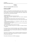
2.2 Nameplate
13
Rated
input
current
(A)
5.0
7.7
11
17
21
31
43
56
71
81
112
132
163
Rated
output
current
(A)
4.5
7
10
16
20
30
42
55
70
80
110
130
160
Applica
ble
motor(
KW)
0.75
1.5
2.2
4
5.5
7.5
11
15
18.5
22
30
37
45
Chapter 2 Product information
Model SY7000-7R5G-4
Power 7.5 KW
Input 3PH AC400V 50HZ
Output 17A 0-600Hz
2.3 Type of SY7000 series inverter
380V series
Inverter
Input
Rated
model
voltage
output
power
(KW)
SY7000-0R7G0.75
4
SY7000-1R5G1.5
4
SY7000-2R2G2.2
4
SY7000-004G/
4.0/5.5
5R5P-4
SY7000-5R5G/
5.5/7.5
7R5P-4
SY7000-7R5G/
7.5/11.0
Three-phas
011P-4
e
380V 11.0/15.
SY7000-011G/
voltage
015P-4
0
range:
-15%
SY7000-015G/
15.0/18.
~
018P-4
5
+15%
SY7000-018G/
18.5/22.
022P-4
0
Rated
input
current
(A)
3.4
Rated
output
current
(A)
2.5
Appli
cable
motor
(KW)
3.7
5.0
5.0
5.8
10.0/15.
0
15.0/20.
0
20.0/26.
0
26.0/35.
0
13.0/17.
0
25.0/32.
0
37.0/45.
0
60.0/75.
0
90.0/11
0.0
35.0/38.
0
150.0/1
76.0
38.0/46.
0
210.0/2
53.0
9.0/1
3.0
17.0/
25.0
32.0/
37.0
45.0/
60.0
75.0/
90.0
110.0
/150.
0
176.0
/210.
0
253.0
/300.
0
340.0
/380.
0
420.0
/470.
SY7000-022G/
030P-4
22.0/30.
0
46.0/62.
0
300.0/3
40.0
SY7000-030G/
037P-4
30.0/37.
0
62.0/76.
0
380.0/4
20.0
14
Chapter 2 Product information
SY7000-037G/
045P-4
37.0/45.
0
76.0/90.
0
470.0/5
20.0
SY7000-045G/
055P-4
45.0/55.
0
90.0/10
5.0
600.0/6
40.0
SY7000-055G/
075P-4
SY7000-075G/
090P-4
SY7000-090G/
110P-4
SY7000-110G/
132P-4
SY7000-132G/
160P-4
SY7000-160G/
185P-4
SY7000-185G/
200P-4
SY7000-200G/
220P-4
SY7000-220G/
250P-4
55.0/75.
0
75.0/90.
0
90.0/11
0.0
110.0/1
32.0
132.0/1
60.0
160.0/1
85.0
185.0/2
00.0
200.0/2
20.0
220.0/2
50.0
105.0/1
40.0
140.0/1
60.0
160.0/2
10.0
210.0/2
40.0
240.0/2
90.0
290.0/3
30.0
330.0/3
70.0
370.0/4
10.0
410.0/4
60.0
0.75
SY7000-250G/
280P-4
250.0/2
80.0
460.0/5
00.0
160.0/1
85.0
SY7000-280G/
315P-4
280.0/3
15.0
500.0/5
80.0
200.0/2
20.0
SY7000-315G/
350P-4
315.0/3
50.0
580.0/6
20.0
250.0/2
80.0
SY7000-350G/
350.0/4
620.0/6
315.0/3
15
2.2
5.5/7.5
11.0/15.
0
18.5/22.
0
30.0/37.
0
45.0/55.
0
75.0/90.
0
110.0/1
32.0
0
520.0
/600.
0
640.0
/690.
0
1.5
4.0/5.
5
7.5/1
1.0
15.0/
18.5
22.0/
30.0
37.0/
45.0
55.0/
75.0
90.0/
110.0
132.0
/160.
0
185.0
/200.
0
220.0
/250.
0
280.0
/315.
0
350.0
Chapter 2 Product information
400P-4
00.0
2.4 Technical specifications
Item
Rated
voltage:
Input
frequency
Allowed
voltage
working
range
Rated
voltage
Output
Frequency
Overload
capacity
Control
mode
Main control
performance
Modulation
mode
Speed
regulation
range
Starting
torque
Speed
stabilization
70.0
50.0
/400.
0
Spec.
380V or 220V: 50Hz/60Hz
Fluctuation range: :≤±1 5 %;Voltage
imbalance rate:<3%
0~380V or 0~220V
0~600 Hz
Type G: 150% of rated current for
60s; 180% of rated current for 1s;
200% of rated current instant
protection;
Type P: 120% of rated current for
60s; 150% of rated current for 1s;
180% of rated current instant
protection
V/F control, Magnetic flux vector
control, Non-PG current vector
control
Space
voltage
vector
PWM
modulation
1:100 (vector control without PG)
150% of rated torque at 2.0 Hz
(Magnetic flux vector control,)
180% of rated torque at 0.5 Hz
(current vector control without PG)
≤±0.2% of rated synchronous speed
16
Chapter 2 Product information
accuracy
Speed
fluctuation
Torque
response
Torque
control
Basic spec.
Resolution
of
input
frequency
Torque
increase
V/F curve
Acc/De
curve
DC brake
Automatic
voltage
regulation
(AVR)
Automatic
current
≤±0.5% of rated synchronous speed
≤100ms current vector control
without PG
Supporting torque control under
vector control mode without PG with
the torque control accuracy of ±5%
Digital setting: 0.01Hz
Analog setting: Max frequency
×0.05%
Automatic torque increase, manual
torque increase 0.1%~30.0%
Six modes: One kind of user setting
V/F curve, four kinds of decrease
torque characteristic curve (2.0
power, 1.7 power, 1.5 power, 1.3
power) and linearity curve
Three
modes:
Straight-line
acceleration and decoration mode,
S-curve acceleration and decoration
mode, shortest acceleration and
decoration mode; four kinds of
acceleration and decoration time: time
unit (minute/second) selected; longest
time: 60 hours
DC braking frequency: 0.0Hz~max
output frequency; braking time:
0.0~50.0s;
braking
current:
0.0%~150.0% of rated current
When the network voltage makes the
change, it can automatically keep the
output voltage constant.
It can automatically limit current
during working to prevent tripping
17
Chapter 2 Product information
limiting
Voltage stall
Automatic
carrier
regulation
Customization
function
Wobble
frequency
control for
spinning
Frequency
combination
function
Fixed length
function
Jogging
control
Multi-speed
running
Built-in
process
closed loop
control
Electric
quantity
calculation
Running
caused by frequent over current.
Control
the
voltage
during
deceleration to prevent over voltage
and protect stopping.
It can automatically regulate carrier
frequency
according
to
load
characteristic
and
temperature
characteristic; and multiple carrier
modes can be selected.
Wobble frequency control for
spinning can realize functions of
fixed wobble frequency and change
wobble frequency
Running command channel and
frequency setting channel can be
optionally combined.
Length achieves stop function and the
max length is 65.535 KM.
Jogging frequency range: 0.00Hz-the
Max; jogging acceleration and
deceleration
time:
0.1-3600.0s,jogging
interval
time:0.1-3600.0s
Realizing multi-speed running via
built-in PLC or control terminal
Realizing the process closed loop
control system conveniently
It can calculate electric energy
consumed by electric motor to
observe
energy-saving
effect
conveniently.
Operation panel, control terminal,
18
Chapter 2 Product information
command
channel
Frequency
setting
channel
Running
function
Auxiliary
frequency
setting
Impulse
output
terminal
Analog
output
terminal
LED display
LCD display
Parameter
copy
Option
of
key function
Protection function
Service
Location
serial port, external expansion setting
can be shifted via various methods.
Three kinds of digital settings, analog
voltage setting, analog current setting,
pulse setting, terminal combination
setting, multi-segment speed setting
and so on
Realizing flexible auxiliary frequency
fine regulation, frequency synthesis
0~50kHz of impulse square signal
output, it can realize physical quantity
output of setting frequency, output
frequency and so on.
Two routes of analog signal output,
output range can be flexibly set
between 0~20mA or 0~10V and it
can realize physical quantity output of
setting frequency, output frequency
and so on.
Displaying sixty-one kinds of
parameters of setting frequency,
output frequency, output voltage and
output current and the like.
NO
NO
Defining function range of part keys
to prevent wrongly operating
Open-phase
protection
(option),
over-current protection, over-voltage
protection, low-voltage protection,
overheat
protection,
overload
protection and off-load protection,
etc.
Indoors, free from direct sunlight,
dust, corrosive gas, combustible gas,
19
Chapter 2 Product information
Altitude
Environment
Ambient
temp.
Humidity
Structure
Efficiency
Vibration
Storage
temp.
Protection
level
Cooling
method
oil mist, water vapor, drip or salt, etc.
Please use it by derating when it is
higher than 1.000m and derated 10%
per increasing 1000m.
-10℃ ~ + 40℃(at 40℃ ~ 50℃ ,
please use it by derating)
Less than 95% RH, no water
condensation.
Less than 5.9 n/s²( 0.6g )
-40℃~ +70℃
IP20
Wind cooling, control with fans
45kW and lower than 45kW≥93%;
55kW and more than 55kW≥95%
20
Chapter 2 Product information
2.5 Outline & installation dimension
2.5.1 Outline diagram
Fig. 2-2 Inverter outline & installation dimension diagram
21
Chapter 2 Product information
2.5.2 Dimensions for mounting hole
22
Chapter 2 Product information
2.6 Options
Name
Instruction
The single-phase 0.75~2.2KW of built-in braking
unit, needing a built-out braking resistor additionally.
Built-in
The three-phase 0.75~15KW of built-in braking unit,
braking unit
needing a built-out braking resistor additionally.
Built-out
Three-phase built-out braking unit of 18.5KW and
braking unit
above.
2.7 Daily maintenance
2.7.1 Daily maintenance
The effect of temperature, humidity, dust and vibration leads to the
aging of inner parts of inverter, potential fault or reduction of service
life of inverter. Therefore, it is necessary to implement the daily and
regular maintenance for inverter.
Daily inspection items
1) Check whether the motor makes some abnormal sound during
running.
2) Check whether the motor has the vibration during running.
3) Check whether the installation environment of inverter is changed.
4) Check whether the cooling fan of inverter works normally.
5) Check whether the inverter is too hot.
Daily cleaning
Keep the inverter clean.
Clear away the dust on the surface of inverter effectively and prevent
the dust entering into the inner part of the inverter, especially the
metallic dust.
Clear away the oil pollution of the cooling fan of inverter effectively.
2.7.2 Regular inspection
Please regularly examine the part that is difficult to be checked during
running.
Regular inspection items
23
Chapter 2 Product information
1) Check the air duct and conduct the regular cleaning.
2) Check whether the screw is slack.
3) Check whether the inverter is corrosive.
4) Check whether the wiring terminal has the track of arc discharge.
5) Main circuit insulation test.
Reminder: When testing the insulation resistance with the
megohmmeter (Please use DC 500V megohmmeter), separate the main
circuit lines from the inverter. Never use the insulation ohmmeter to test
the insulation of control circuit. HV test needn’t to be performed,
because this test has been finished before the inverter leaves factory.
2.7.3 Change of wearable parts of inverter
The wearable parts of inverter include the cooling fan and electrolytic
capacitor for filtering and their service life is closely related to the
service environment and maintenance.
User can determine the age limit according to the running time.
1) Cooling fan
Possible cause for damage: Bearing abrasion and blade aging.
Examination standard: Check whether the fan blade has cracks and
whether the fan has some abnormal vibration sounds when it is started.
2) Electrolytic capacitor for filtering
Possible cause for damage: Bad quality of input power, higher
environment temperature, frequent jump of load and aging of
electrolyte.
Examination standard: Leakage of liquid, projection of safety valve and
test of static capacitance and insulation resistance.
2.7.4 Storage of inverter
After user purchases the inverter, please pay attention to the following
points for temporary storage and long-time storage.
1) Try your best to put the inverter with the original package into our
packing case when it is stored.
24
Chapter 2 Product information
2) The long-term storage will result in degradation of electrolytic
capacitor, so the inverter must be electrified once every two years,
the electrified time should be 5 hours at least and the input voltage
must rise to the rated value step by step with the voltage regulator.
2.8 Guidance for selecting type
Two control modes are available: Common V/F control and SVC
control.
When selecting the inverter, first, you must identify the system
technical requirements of frequency-conversion speed regulation,
application location of inverter, load characteristics, etc.. and take the
applicable motor, output voltage, rated output current, etc. into the
consideration, then to select the machine type at your request and
determine the running way.
Basic principle: The rated load current or motor should not exceed the
rated current of inverter, in general, select the inverter according to the
applicable motor capacity that is specified as the manual, please
compare the rated current of motor with that or inverter. The overload
capacity of inverter makes actually sense to the starting and braking
operation. Whenever the inverter has the short-time over load, the load
speed will be changed. If the speed accuracy is demanding, please take
a higher class into current.
Fan and water pump type: The overload capacity is undemanding.
Because the load torque is directly proportional to the square of speed,
the load (except the rose fan) is very light when it runs at a low speed.
And these loads have no special requirements on the rotation accuracy,
so the square torque V/F is selected.
Constant-torque load: Many loads such as the extruder, agitator
conveyer belt, plant trolley, crane translating mechanism have the
constant-torque characteristics; however, their rotation speed and
dynamic performance are undemanding. Accordingly, multi-segment
V/F operation way is available when choosing the type.
The controlled object has a certain dynamic and static state requirement:
The strong mechanical characteristics are required for this type of load
when it runs at a low speed, to meet the control system requirements of
dynamic and static indicators, SVC control way is available.
25
Chapter 3 Mechanical and electrical installation
3.1 Mechanical installation
3.1.1 Installation environment
1) Environment temperature: The ambient temperature has a large
impact on the service life of inverter, and the running environment
temperature of inverter should not exceed the temperature of -1 0℃ ~
50℃.
2) The inverter is installed on the surface of flame-retardant object; and
it should have the enough space for ventilation, because it produces
much heat easily when working. And, it should be vertically installed at
the mounting rack with the screw.
3) Please install it in the firm area with easy vibration occurrence. The
vibration should not be more than 0.6G. Especially, it should be kept
away from the punch.
4) It is installed in the area free from the direct sunlight, dampness and
drip.
5) It is installed in the area free from the corrosive, flammable,
explosive gas, etc..
6) It is installed in the position free from the oil pollution, much dust
and metallic dust.
3.1.2 Prompt for installation environment
Monomer installation diagram
Fig.3-1 Installation gap
26
Chapter 3 Mechanical and electrical installation
Note: When the inverter power is not larger than 22KW, the dimension
A may not be taken into consideration, and when larger than 22KW, the
dimension A should be larger than 50mm.
Top and bottom installation diagram
Fig.3-2 Installation of multi inverters
Note: When the inverter is installed vertically, please mount a
heat-insulated baffler shown as Fig.3-2.
Please pay attention to the following points about heat emission when
performing the mechanical installation.
1) The inverter should be installed vertically, which enables the
heat to emit upwards easily, but it should not be mounted
reversely. If many inverters need to be installed in a cabinet,
you’d better install them side by side. If the inverts need the top
and bottom installation, please mount a heat-insulated baffler
shown as Fig.3-2.
2) Make sure the inverter has enough space for heat emission and
the installation space is shown as Fig.3-1. However, when
laying it, please consider the heat emission of other parts in the
cabinet.
3) The mounting rack must be made of the flame-retardant
27
Chapter 3 Mechanical and electrical installation
materials.
4) For the area with full metallic dust, it is suggested the
installation outside the cabinet of radiator should be adopted and
the space inside the full-seal cabinet should be as large as
possible.
3.1.3 Dismounting and mounting of lower cover plate
SY7000 series inverter of 22KW below adopts plastic shell, exposed
main circuit terminal without disassembling the cover plate.
SY7000 series inverter of 30KW above adopts a sheet metal enclosure;
and the lower cover plate of the sheet metal enclosure needs to be
dissembled just through slacking the screw of the lower cover plate
directly.
28
Chapter 3 Mechanical and electrical installation
3.2 Electrical installation
3.2.1 Circuit breaker, cable and contactor
Inverter mode
Circuit
Input/output wire
breaker
(Copper wire and
cable)
(A)
SY7000-0R7G-2/S2
SY7000-1R5G-2/S2
SY7000-2R2G-2/S2
SY7000-004G-2
SY7000-5R5G-2
SY7000-7R5G-2
SY7000-011G-2
SY7000-015G-2
SY7000-018G-2
SY7000-022G-2
SY7000-030G-2
SY7000-037G-2
SY7000-045G-2
SY7000-0D7G-4
SY7000-1R5G-4
SY7000-2R2G-4
SY7000-004G/5R5P-4
SY7000-5R5G/7R5P-4
SY7000-7R5G/011P-4
SY7000-011G/015P-4
SY7000-015G/018P-4
SY7000-018G/022P-4
SY7000-022G/030P-4
SY7000-030G/037P-4
SY7000-037G/045P-4
SY7000-045G/055P-4
SY7000-055G/075P-4
SY7000-075G/090P-4
SY7000-090G/110P-4
SY7000-110G/132P-4
16
20
32
40
63
100
125
160
160
200
200
200
250
10
16
16
25
25
40
63
63
100
100
125
160
200
200
250
315
400
29
2.5
4
6
6
6
10
16
25
25
35
35
50
70
2.5
2.5
2.5
4
4
6
6
6
10
16
25
25
35
35
50
70
95
Contactor
(A)
10
16
20
25
32
63
95
120
120
170
170
170
230
10
10
10
16
16
25
32
50
63
80
95
120
135
170
230
280
315
Chapter 3 Mechanical and electrical installation
SY7000-132G/160P-4
400
150
380
SY7000-160G/185P-4
630
185
450
SY7000-185G/200P-4
630
185
500
SY7000-200G/220P-4
630
240
580
SY7000-220G/250P-4
800
150*2
630
SY7000-250G/280P-4
800
150*2
700
SY7000-280G/315P-4
1000
185*2
780
SY7000-315G/350P-4
1200
240*2
900
SY7000-350G/400P-4
1200
240*2
900
3.2.2 AC input reactor
The input AC reactor can resist the high-order harmonic wave of input
current of inverter, and obviously improves the power factor of inverter.
It is suggested that the input AC reactor should be used under following
conditions:
1) The ratio of power capacity for inverter and the capacity of
inverter reaches over 10:1.
2) The thyristor or power factor compensating device with the
switching control is connected at the same power supply.
3) The voltage unbalance degree of three-phase power is quite
large (more than 3%).
4) If the power factor on power side needs to be improved, the
power factor can be increased to o.75~0.85.
AC input reactors of common specifications are shown as the following
table.
Spec.& mode
Power
Current Inductance Voltage
(KW) (A)
(MH) drop( V )
ACL-0005-EISC-E3M8
1.5
5
3.800
2%
ACL
00072.2
7
2.500
2%
EISC-E2M5
ACL-0010-EISC-E1M5
3.7
10
1.500
2%
ACL-0015-EISH-E1M0
5.5
15
1.000
2%
ACL- 0 0 2 0- E I S H 7.5
20
0.750
2%
EM75
A C L - 0 0 3 0- E I S H
11
30
0.600
2%
-EM60
A C L - 0 0 4 0- E I S H
15
40
0.420
2%
30
Chapter 3 Mechanical and electrical installation
-EM42
A C L - 0 0 5 0- E I S H
18.5
50
0.350
2%
-EM35
A C L - 0 0 6 0- E I S H
22
60
0.280
2%
-EM28
A C L - 0 0 8 0- E I S H
30
80
0.190
2%
-EM19
A C L - 0 0 9 0- E I S H
37
90
0.190
2%
-EM19
A C L - 0 1 2 0- E I S H
45
12
0.130
2%
-EM13
A C L - 0 1 5 0- E I S H
55
150
0.110
2%
-EM11
A C L - 0 2 0 0- E I S H
75
200
0.080
2%
-EM08
A C L - 0 2 5 0- E I S H
90/110
250
0.065
2%
-E65U
A C L - 0 3 3 0- E I S H 132/160
330
0.050
2%
-EM05
A C L - 0390- E I S H 185
400
0.044
2%
E 44 U
A C L - 0 490- E I S H - 220/200
490
0.035
2%
E 35 U
A C L - 0 660- E I S H - 250/280
530
0.025
2%
E 25 U
A C L - 0 660- E I S H 315
660
0.025
2%
E 25 U
ACL-0800-EISH-E25U
355
800
0.025
2%
3.2.3 AC output reactor
The AC output reactor is used for resist the emission interface and
inductance interface of inverter as well as the voltage fluctuation of
motor; and it also can prevent the wire on output side leaking the
electricity and reduce the electricity leakage when multi motors work in
parallel and wire is laid at along distance.
AC output reactors of common specifications are shown as the
following table.
31
Chapter 3 Mechanical and electrical installation
Spec.& mode
ACL-0005-EISC-EIM5
ACL- 0007- E I S C - E
IM0
ACL- 0 0 1 0- E I S C EM60
ACL- 0 0 1 5- E I S H EM25
ACL- 0 0 2 0- E I S H EM13
ACL- 0 0 3 0- E I S H E87U
ACL- 0 0 4 0- E I S H E66U
ACL- 0 0 5 0- E I S H E52U
ACL- 0 0 6 0- E I S H E45U
ACL- 0 0 8 0- E I S H E32U
ACL- 0 0 9 0- E I S H E32U
ACL- 0 1 2 0- E I S H E23U
ACL- 0 1 5 0- E I S H E19U
ACL- 0 2 0 0- E I S H E14U
ACL- 0 2 5 0- E I S H E11U
ACL- 0 3 3 0- E I S H EM01
ACL- 0 3 9 0- E I S H E8U0
ACL- 0 4 9 0- E I S H -
Power
(KW)
1.5
2.2
Current
(A)
5
7
Inductance
(MH)
1.500
1.000
Voltage
drop( V )
0.5%
0.5%
3.7
10
0.600
0.5%
5.5
15
0.250
0.5%
7.5
20
0.130
0.5%
11
30
0.087
0.5%
15
40
0.066
0.5%
18.5
50
0.052
0.5%
22
60
0.045
0.5%
30
80
0.032
0.5%
37
90
0.032
0.5%
45
12
0.023
0.5%
55
150
0.019
0.5%
75
200
0.014
0.5%
90/110
250
0.011
0.5%
132/160
330
0.010
0.5%
185
400
0.008
0.5%
220/200
490
0.005
0.5%
32
Chapter 3 Mechanical and electrical installation
E5U0
ACL- 0 6 6 0- E I S H - 250/280
530
0.004
0.5%
E4U0
ACL - 0 6 6 0- E I S H
315
660
0.004
0.5%
-E4U0
ACL-0800-EISH-E5U0
355
800
0.005
0.5%
3.2.4 DC reactor
When the capacity of power grid is far larger than that of inverter, or
the power capacity is larger than 1, 000KVA, the power factor is
demanded higher, the DC reactor should be installed at DC immediate
link buses. The reactor may input high order harmonic. The series of
inverter of 30KW above can be equipped with the DC reactor and the
inverter of 160KW above has the built-in DC reactor.
DC reactors of common specifications are shown as the following table.
Spec.& mode
Power(KW)
Current(A) Inductance
(MH)
D CL-0006-EIDC
1.5/2.2
6
11
D CL-0012-E I D
3.7
12
6.3
C
D CL-0023-E I D
5.5/7.5
23
3.6
H
D CL-0033-E I D
11/15
33
2.0
H
D CL-0040-E I D
18.5
40
1.3
H
D CL-0050-E I D
22
50
1.08
H
D CL-0065-E I D
30
65
0.8
H
D CL-0078-E I D
37
78
0.7
H
D CL-0095-E I D
45
95
0.54
H
D CL-0115-E I D
55
115
0.45
H
D CL-0160-E I D
75
160
0.36
33
Chapter 3 Mechanical and electrical installation
H
D
H
D
H
D
H
D
H
D
H
D
H
CL-0180-E I D
90
180
0.33
CL-0250-E I D
110/132
250
0.26
CL-0340-E I D
160
340
0.17
CL-0460-E I D
185/200/220
460
0.09
CL-0650-E I D
250/280
650
0.072
CL-0800-E I D
315/355
800
0.072
3.2.5 Braking unit and braking resistor
When the braking torque is 10%, the resistance value and the power of
a braking resistor of common specification are shown as the following
table.
Voltage
Inverter
Braking
unit Braking power (1 0 % E
power
(V)
(10 % E D)
D)
(K W)
Spec.
Qty.
Spec.
Purchase
380
0.4
0.75
1.5
2.2
3.7
5.5
7.5
11
15
18.5
22
30
37
4030
4030
4030
4045
1
1
1
1
34
70W/750
70W/750
260W/400
260W/250
390W/150
520W/100
780W/75
1040W/50
1560W/32
4800W/27.2
4800W/27.2
6000W/20
9600W/16
1
1
1
1
1
1
1
1
1
1
1
1
1
Chapter 3 Mechanical and electrical installation
45
55
75
110
160
185
220
300
4045
4030
4045
4220
4220
4220
4220
4220
1
2
2
1
1
1
1
2
9600W/13.6
6000W/20
9600W/13.6
9600W/20
9600W/13.6
9600W/13.6
9600W/16
9600W/13.6
3.2.6 Connection diagram of peripheral equipments
35
1
2
2
3
4
4
5
6
Chapter 3 Mechanical and electrical installation
3.3 Connection way
Note) ● display main circuit terminal; ○ display control signal terminal
1. The terminal construction is different according to the difference
of different module.
2. Analog speed command can be set simultaneously by voltage,
current or respectively.
3. The public bus between P1 and P2 must be removed when
installing DC reactor.
4. Built-in a braking circuit in the circuit board for 0.7~15 KW
inverter.
36
Chapter 3 Mechanical and electrical installation
3.4 Main circuit terminal and connection
3.4.1 Instruction for the main loop
inverter:
Terminal mark
Name
Three-phase
R、S、T
power input
terminal
Inverter
U、V、W
output
terminal
Positive and
P+、Pnegative
terminals of
DC bus
Connection
P+、BR
terminal of
braking
resistor
Earthing
terminal
37
terminals of three-phase
Description
AC three-phase 380V
power connection points
Connecting
three-phase motor
with
Common DC bus input
point; connection point of
external braking unit or
18.5 KW and above
Connecting
point
of
braking resistor of 15 KW
and below
Earthing terminal
Chapter 3 Mechanical and electrical installation
3.4.2 Attentions for wiring:
1) Input power R, S and T:
The connection on the input side of inverter has no requirement of
phase sequence.
2) DC bus P+ and P- terminals:
Note: After the power supply is just cut off, the DC bus P+ and P- still
have residual voltage, only the lamp in the power panel goes out and
the voltage is less than 36V, you can touch the inverter, otherwise, the
electric shock accident will happen.
When selecting the built-out braking unit for the inverter of 18.5 KW
and above, never connection the polarity of terminals P+ and Preversely, otherwise, the inverter will be damaged, even the fire will
happen. The wiring length of braking unit should not exceed 10m and
the wire must be twisted in pairs or compact double-wire.
3) Braking resistor connection terminals P+ and PThe inverter of 15 KW and below has been provided with a built-in
braking unit so only the braking resistor is connected to terminals P+
and BR.
Please refer to the recommended values for the type selection for
braking resistor and the wiring distance should be less than 5m,
otherwise, the inverter will be damaged.
4) Inverter output side terminals U, V and W:
The capacitor or surge absorber should not be connected on the output
side of the inverter; otherwise, the inverter will suffer from frequent
protection or damage.
If the motor cable is too long, the electric resonance will be easily
produced for the effect of distributed capacitance to cause the damage
of motor insulation or produce large leakage current to make the
inverter perform an over-current protection. If the motor cable is longer
than 50m, the AC output reactor must be mounted additionally.
5) Earthing terminal
The terminal must be reliably earthed, the resistance of earthing wire
should be less than 5Ω, otherwise, the equipment will work abnormally,
even to be damaged. Never commonly use the earthing terminal and
power neutral line N terminal.
38
Chapter 3 Mechanical and electrical installation
3.5 Control terminal and connection
3.5.1 Layout of control loop terminal function:
Fig.3-1 0.75 KW-2.2 KW (G type) Control loop terminal diagram 1
Fig.3-2 2.2 KW (C type) Control loop terminal and above diagram 2
In order to reduce interference and attenuation, connection length of
control signal should be
Limited within 50m and the gap with the power wire is more than 30
cm. Try best to avoid wiring the control wire parallel with the power
wire. When connecting the analog input and output signal, please use
shielding twisted-pair. And the concrete function of terminal is shown
as follows
Type
Termin
Name
Function
Spec.
al
instruction
markin
g
AI 1
Analog input Receiving
Input voltage
1
voltage/current range:0~
flow
input, 10V
choose by J1, (input
Analog input
Analog input AI2
receive resistance:
AI 2
2
voltage signal 100 kΩ)
and
current Input current
signal
,AI1 range:0~20
only receive mA(input
voltage signal.
resistance:
defaulting
input voltage 500Ω)
39
Chapter 3 Mechanical and electrical installation
Analog
output
A01
Analog
output 1
A02
Analog
output 2
40
when leaving
factory. Range
setting
function code
P 6.00~P6.11
instruction (J1
selection, see
2.1
analog
input terminal
wiring).
( Reference
ground:GND)
Providing
output
of
analog
voltage/
current flow,
AO2 receive
voltage
and
current signal,
AO1
only
receive current
signal.
Selecting by
jump wire J2;
defaulting
output voltage
when leaving
factory.
Correspond
output
frequency
(before
compensating
slip) see the
function code
P6.18~P6.19
Current
output range:
0/4~20 mA
Voltage
output range:
0/2~10V
Chapter 3 Mechanical and electrical installation
485A
Rs 485
Communicati
on interface
Communicati
on
485B
X1
X2
X3
Multifunctio
nal
input
terminal
X4
X5
X7
X8
Multifunctio
nal
input
terminal 1
Multifunctio
nal
input
terminal 2
Multifunctio
nal
input
terminal 3
Multifunctio
nal
input
terminal 4
Multifunctio
nal
input
terminal 5
Multifunctio
nal
input
terminal 7
Multifunctio
nal
input
41
instruction. (J2
selection see
analog output
terminal wire)
( Reference
ground:GND)
485
differential
signal positive
terminal
(485+)
485
differential
signal negative
terminal (485-)
Capable
of
programming
to define as
multifunctiona
l switch vector
input terminal,
which reaches
99.
See
function
instruction of 7
groups of input
terminals
(Public
terminal
:
COM)
Standard
RS-485
communicati
on interface,
please
use
twisted-pair
or
shielded
wire
and
GND without
separation
light-coupled
isolation
input
Input
impedance
R=3.9 Ω
Highest input
frequency:
200HZ
Input voltage
range:
20~30V
Chapter 3 Mechanical and electrical installation
terminal 8
Multifunctio
n
output
terminal
X6
Multifunctio
nal
input
terminal 6
D01
Open-circuit
collector
impulse
output
terminal
Y1
Two-way
open circuit
collector
output Y1
42
X6 can be
taken
as
common
multifunctiona
l terminal and
can
be
programmed
to be high
speed impulse
input terminal.
See
P7.05
function
instruction.
(Public
terminal
:
COM)
Programming
various
function
of
impulse signal
output
terminal,
which
can
reach 99. See
P7.19, P7.19
output
terminal
function
instruction.
(Public
terminal
:
COM)
Programming
various
function
of
switch vector
light-coupled
isolation
input
equivalent
diagram
as above
Max
input
frequency:
50KHz
Input voltage
range: 0~30V
Collector
open-circuit
output
frequency
range: setting
the
highest
frequency at
50KHz from
P6.29~P6.32
Collector
open-circuit
output
of
light-coupled
Chapter 3 Mechanical and electrical installation
Y2
Two-way
open circuit
collector
output Y2
TA1
TB1
TC1
TA2
TB2
Relay output
terminal
Relay output
TC2
Power
supply
+10V power
10V
24V
+24V power
COM
+24V power
common
43
output
terminal,
which
can
reach 99. See
P7.19, P7.19
output
terminal
function
instruction.
(Public
terminal
:
COM)
Capable
of
programming
to define as
multifunctiona
l switch vector
input terminal,
which reaches
99. See P7.20
P7321 output
terminal
function
instruction
Providing
+10V power
supply outside
(reference
ground: GND)
Providing
+24V power
supply outside
(reference
ground: GND)
reference
ground
of
isolation
working
voltage
range:
12V~30V
Max output
current:
50mA
RA-TB:
always closed
TA-TC:
always
opened
Contac
capacity: 2 5
0VAC/2A
( C O SΦ= 1 )
250VAC/
1 A ( COSΦ=
0.4 )
30VDC /1A
Max output
current 20mA
Max output
current
200mA
Internal
CND
and
Chapter 3 Mechanical and electrical installation
GND
terminal
+10V power
reference
ground:
+24V power
Analog signal
and
+10V
power
reference
ground:
Safe ground
Safe
ground
connection
terminal,
analog signal
wire, shielding
layer of 485
communicatio
n
can
be
connected with
the terminal
EART
H
44
separation
Internal
separating
from COM
and
CME,
+10V,
AII,
AI2 A01 and
A02
signal
reference
ground:
Resistance of
safe ground
to ground is
less than 10Ω
Chapter 3 Mechanical and electrical installation
3.5.2 Control loop terminal wiring
Analog input terminal wiring
AI2 terminal receives analog signal input, I-I and U-I jump wire selects
input voltage (0~10V) or input current (0~20mA). Terminal wire mode
is shown as Fig. 3-3
Fig. 3-3 Analog input terminal wiring diagram
Analog output terminal wiring
Analog output terminal A02 externally connects with an analog meter
can indicate multiple physical quantities, respectively select output
voltage (0/2~10V) or output current (0/4~20 mA) by jump wire I-0 and
U-0. Terminal wire mode is shown as Fig. 3-4:
Tips:
1) It means current and voltage respectively when J1 and J2 jump to
“I” and “V”.
2) Analog input/output signals are easily interfered, so shielded
cabled must be adopted and grounded while wiring. The wire
should be short enough.
3) When frequency converter analog input connects analog signal
output device, analog signal output device or frequency may be
interfered and therefore causes errors. In this circumstance, we can
connect a
4) capacitance or hard magnetic ring (wind three times) of
0.01~0.1uF/50V to the external analog output device.
45
Chapter 3 Mechanical and electrical installation
3.5.3 Serial Communication Interface
This kind of frequency converter provides users with standard RS485
serial communication interface, helping to form a master-slave control
system. With host PC (PC or PLC controller), real-time, remote,
automatic and even more complex monitoring can be realized.
Fig. 3-5 Host PC and frequency converter interface and cable
connection diagram
Interference in communication increases when a number of frequency
converters are connected to the same RS485 system. The upper limit of
frequency converters connected to one RS485 system through USB is
247. Wiring is very important. The bus must be shielded twisted pair.
We recommend the following wiring method:
Fig. 3-6 Recommended wiring method for PLC/frequency converter
multi-computer communication
The host computer can be PC or PLC, and the slave computers are
frequency converters. If PC is the host computer, a RS232/RS485
46
Chapter 3 Mechanical and electrical installation
adapter should be added between host computer and bus. If PLC is the
host computer, all you have to do is to connect RS485 terminals
between host computer and slave ones.
If more than one frequency converters are connected to one RS485
system, the signal interfaces of frequency converts on both ends must
be connected to shielded resistances (generally100 Ω/1/4w).
If the above wiring does not work, please try the following measures:
1) Power PLC (or Host PC) independently, or separate their power
sauce from others’.
2) If RS232/RS485 adapter is adopted, try powering the adaptor
independently. Adaptor with optical coupler is strongly
recommended.
3) Use magnetic poles in communication lines. If it is possible, reduce
the carrier frequency of frequency converter.
3.5.4 Multifunction Input Terminal Wiring
The multifunction input terminal of this frequency converter adopts the
full bridge rectifier. 24V is the common power terminal of X1~X7 that
will fall to 5V after optical coupling isolation during output and a
direction connection to CPU is realized. Input is effective when the
switch and COM close. The wiring method is shown in Fig 3-7.
Fig. 3-7 Multifunction input terminal wiring
Source-drain method
1) Use the internal +24V power of the frequency converter; the
external controller connects NPN-shape emitter and supports its
47
Chapter 3 Mechanical and electrical installation
output. Please refer to Fig. 3-8.
Fig.3-8 Source connection of using frequency converter’s internal +24
power
2) Use the internal +24V power of the frequency converter; the
external controller connects PNP-shape emitter and supports its
output. Please refer to Fig. 3-9.
Fig. 3-9 Drain connection of using frequency converter’s internal +24
power
3.5.5 Multifunction Output Terminal Wiring
1) Multifunction output terminals Y1 and Y2 are adaptable to the 24V
power of frequency converter. The wiring method is shown in Fig 3-10.
48
Chapter 3 Mechanical and electrical installation
Fig. 3-10 Multifunction output terminal connection
3) Digital pulse frequency output DO is adaptable to frequency
converter’s power of 24 V. The wiring method is shown in Fig.
3-11.
Fig. 3-11 Output terminal DO connection
3.5.6 Relay Output
TA2/TB2/TC2 Wiring.
Terminal
TA1/TB1/TC1
Wiring
and
If an inductive load (such as electromagnetic relay and contactor) is
driven, a surge voltage absorbing circuit like RC absorbing circuit,
VDR or free wheeling diode (used in direct current electromagnetic
circuit, note the polar of diode) must be added. Absorbing circuit
components must be installed at the ends of relay or contactor loops.
Tips:
1) Do not shorten 24V terminal and COM terminal; otherwise it
49
Chapter 3 Mechanical and electrical installation
would cause damage of the control panel.
2) Connect control terminals with multi-core shielded cable or twisted
pair (over 1m ㎡).
3) While using shielded cable, the terminal near the frequency
converter should be connected to the earthed terminal PE through
corresponding clamps.
4) Keep the cables over 30 cm away from main circuit and
heavy-current circuits (including power line, machine wire, relay
wire, contactor connections, etc.). Do not place them in parallel. To
avoid errors caused by interference, do not interlock or intersect
control cables and heavy-current cables.
3.6 Solutions for EMC problems
3.6.1 Influence of harmonic
1)The high order harmonic of power supply will bring about the
damage of inverter, therefore, it is suggested that AC input reactor
should be mounted in the area where the power grid is quite bad.
2)Because there is high order harmonic appearing on the output side
of the inverter output side, therefore, the capacitor for improving the
power factor and surge suppressor may suffer from the electrical
vibration on the output side, thus, the equipment will be damaged.
Accordingly, the capacitor or surge suppressor should not be mounted
on the output side.
3.6.2 Electromagnetic interference and solution
1)Two kinds of electromagnetic interference
One is the interference from the peripheral electromagnetic noise
which leads to the error operation of inverter itself. This interference
has the low impact, because the inverter has the internal treatment
against it when being designed, with the strong ability to resist the
interference. The other is the inverter impact on peripheral equipment.
50
Chapter 3 Mechanical and electrical installation
Common solutions
① The earthing wires of inverter and other electrical products
should be earthed well, and the earthing resistance should not be
larger than 5Ω.
② The dynamo—power line of inverter should not be laid with the
control circuit in parallel, they can be vertically laid if available.
③ Where the interference resistance is demanding, the power line
from the inverter to motor uses the shielded cable, the shielded
layer should be earthed reliably.
④ The lead of interfered equipment should be shielded twisted pair,
and the shielded layer should be earthed well.
2)Solutions against the interference from the peripheral
electromagnetic equipment
The electromagnetic impact comes from many relays, contactors or
electromagnetic brakes that are installed around the inverter. If the
inverter performs the error operations for the interference from
abovementioned equipment, the following solutions may be taken.
① A surge suppressor is mounted at the equipment that can produce
the interference.
② The filter is mounted at the input terminal of inverter.
③ The control signal wire of inverter and lead of detection circuit
adopt the shielded cable, and the shielded layer should be
earthed reliably.
3)Solutions against the inverter noise interference to peripheral
equipment:
The noise comes from two operations: one is the emission of inverter
itself, the other is the emission of lead from the inverter to motor.
These two kinds of emission enable the surface of lead of peripheral
electric equipment to suffer from the electromagnetic and static
inductance, so that the equipment actuates the error operation. For
51
Chapter 3 Mechanical and electrical installation
abovementioned different interferences, the following methods can be
taken for handling.
① The signal of metering meter, receiver and sensor are quite weak,
if they are mounted near the inverter or installed with the inverter in
the same control cabinet, they will be interfered easily and performs
the error operation. The following methods may be taken to handle
against the interference: keep them away the interference source as far
as possible, don’t lay the signal wire and power line in parallel,
especially, don’t bind them in parallel; adopt the shielded cable as the
signal wire and power wire; mount the linear filter or wireless noise
filter on the input and output side of inverter.
②When the interfered equipment and inverter use the same power
supply, if the above methods are useless for eliminating the
interference, the linear filter or wireless noise filter should be mounted
between the inverter and power supply.
③ The peripheral equipment should be earthed independently, thus,
in commonly earthing, the interference from the leakage current
that is produced by the earthing wire of inverter may be avoided.
4)Leakage current and solutions
The leakage current includes line-to-line leakage current and
to-earth leakage current.
① Causes for impacting the to-earth leakage current and
solutions
The distribution capacitance appears between the inverter and ground,
the larger the distribution capacitance is, the larger the leakage current
will be; this distribution capacitance may be reduced through
efficiently reducing the distance from inverter to motor. And, the
larger the carrier frequency, the larger the leakage current will be. This
leakage current may be lowered by reducing the carrier frequency.
However, please pay attention to that the reduction of carrier
52
Chapter 3 Mechanical and electrical installation
frequency will lead to the increase of motor noise. The installation of
reactor is also an effective method for eliminating the leakage current.
As the leakage current increases with the loop current, the larger
power of motor will bring the larger leakage current.
②Causes for producing line-to-line leakage current and
solutions
The distribution capacitance appears among the output wires of
inverter, if the current passing through the circuit includes the high
order harmonic, the resonance will be caused that will produce the
leakage current. In this case, if the thermal relay is used, the inverter
will actuate some error operations.
The solution is to reduce the carrier frequency or mount an output
reactor. It is suggested the thermal relay should not be mounted in
front of motor when using the inverter and the electronic overheat
protection function should be used.
53
Chapter 4 Operation and Display
4.1 Introduction for operation and display interface
Operation keyboard is the main unit for inverter receiving commands
and displaying parameter. The panel outline is shown as fig.-1.
Fig. 4-1 SY7000 operation panel deployment diagram
4.1.1 Instruction for button function
There are 8 buttons for operating the inverter and function of each
button is defined as Table 4-1.
Table 4-1 Functions of operating keyboard
Button
Name
Function
symbol
P R O G PROGRAM /EXIT Let primary menu enter or exit
key
Enter into the menu picture step by step,
ENTER key
confirm the setting parameters
In the “shutdown” interface and “run”
interface, move to right and circularly
S H I F SHIFT key
select the displayed parameters, in
T
amending the parameters, please select
the amended places of parameters.
In the mode of keyboard operating, it is
RUN
RUN key
used for “RUN” control.
54
Chapter 4 Operation and Display
Stop/Reset key
UP key
DOWN key
Inverter is in normal operation, if the
inverter running Settings are Stop
effectively for the keyboard, press this
button to set Stop.
Inverter is in fault, press this button to
reset inverter, and returns to normal Stop.
Increase the data or function code
(continuous press can increase speed),
Decrease the data or function code
(continuous press can decrease speed),
4.1.2 Instructions of LED digital pipe and lights
1) Instructions of function indicators
Names of Instructions of function indicators
indicators
The out- lamp means the inverter stops; on –light means
the inverter is in motion, Flashing lamp means the inverter
RUN
is self-learning states
Keyboard, terminal operations and remote communication
control indicators,
L O C / R Out- lamp means control of Keyboard, flashing Lights
EM
means control of terminal operation; on-lamp means
remote operation control
F W D / R Positive &negative indicator, out-lamp turns positive,
EV
on-lamp turns negative
FLT
Failure indicator., When in fault , on; when at normal ,out
HZ
Frequency unit
V
Voltage unit
A
Current unit
2) Digital pipe displaying areas
50.00 for L E D display, That is, displaying Settings frequency, output
frequency, etc. Various monitoring data, and alarm code.
4.1.3 Keyboard displaying state
SY7000 operating keyboard displaying state is divided into electricity
initialization display, functional code parameters and monitor parameter
55
Chapter 4 Operation and Display
display, Fault alarm status display, running parameter display four state.
This machine is on, L E D indicators are on, then digital tube (L E D)
will show” p. o F F” characters, and then come to setting frequency, as
shown in figure 4-2
4.1.4 Outage parameter displaying state
When the inverter stops operating keyboard displays stopping
monitoring parameters, leaving the factory, set digital frequency Rate.
As shown in figure 4-3 the unit of digital tube lights shows that the
parameters of the unit H z. Outage parameter depends on group Dmonitoring parameters, as follows is table D- 0 0 D - 57.
Users Can press PRG key (twice) into monitoring parameters, press
Enter and ▲ key to check each of Control parameters
4.2 The status of operation parameter display
After the inverter received the efficient order, into operation state
Operation status monitoring parameters shown by operation keyboard
Output frequency is default in factory .As illustrated 4-4, the unit is HZ
shown on indicator’s parameter of the unit above the digital tube. It
may via
key (two times) into monitor interface , via
with
, can check the monitor parameter one by one , read the
function details in d-00 d-57 table.
As illustrated 4-2,
is shown on electricity initialization of the
electricity parameter display state.
As illustrated 4-3, the setting frequency of stopping is shown “50.00” of
the machine when stopped parameter display state
As Illustrated 4-4, output frequency when running shown by
on the running parameter display state
4.3 Fault alarm display state
When the fault signal is detected by the fault alarm display inverter, is
entering the fault alarm display state, the display fault code is as
illustrated 4-5, when the fault information should be checked, press
into the programming state to inquire the parameter of group D.
56
Chapter 4 Operation and Display
After checked and exclude the fault, can via
of operation
keyboard, controlling the terminal or telecom order to reset the fault
operation. If the fault exists all the time, the fault code will be shown
constantly.
As illustrated 4-5
The flow when accelerating of fault alarm display
Note: Refer to some serious fault, such as inverter modules,
over-current, over voltage etc. When never confirm excluding the fault,
it should not be reset operating absolutely, it should run again in order
to avoid damaging the inverter
4.4 Editing display state of function code
When it is the status of halting, running or fault alarming, press
to enter editing state. If user password has been set, the password
should be inputted to enter editing state. The 5.3 for reference, editing
state is as per method of level 2 menus to display. Press
to enter
as per levels. When under the state of parameter display, press
to operate the storing parameter, but it won’t be saved if press
, only return to upper menu.
57
Chapter 5 Function parameters table
5 Keyboard operation instructions
The operation of frequency converters can be made by operating
keyboard. Examples below:
5.1 Monitor parameter check
EX 1: Examine monitor parameter item d-05 (output current)
Method one:
1) Press
button into program status, LED shows function
parameter P0.00. Press
button again, LED shows
function parameter d-00, and flashing position stays in units.
Regulate
or
button till monitor code is d-05.
2) Press
button, you will see the data corresponding to d-05.
At the same time, LED (A) corresponding to the unit “ampere”
shines.
3) Press
Method two:
1) Press
button to exit monitor status.
button in the interface of specific monitor model,
jump to next monitor parameter item d-xx. Press
button
and regulate flashing position to units of monitor parameter. Next
regulate
or
button till monitor code is d-05. At
last, repeat method one’s steps 2), 3), it will be finished.
EX 2: Check monitor parameter in fault state
Instruction:
1) Users can check D group’s monitor parameter by pressing
button in fault state. Check range is D-00 ~ D-57.
2) When the use is checking fault parameters, it will switch back to
fault alarm show state after stopping operating for 5s if the fault is
not solved.
3) Fault code shows in D-48~D-57 (current and first three times).
5.2 Set function code parameter
This frequency converter’s functional parameter system includes
function code P0 ~ PP, fault code E group and monitor code D group.
Each function group covers some function codes. Function code takes
“function group number + function code number” mode to recognize,
58
Chapter 5 Function parameters table
for example, “P5. 08” indicates the 8th function code in 5th function
group.
Examples of setting functional code:
EX 1: Change normal inching turning frequency from 5 Hz into 10 Hz.
(Change P2.21 from 5.00 Hz to 10.00 Hz).
1) Press
button into program status. LED shows functional
parameter P0.00, flashing position stays in units.
2)
3)
4)
5)
Press
button, you will see flashing position shines in
hundreds place, tens place and units place of the function item.
Press
or
button to change corresponding place’s
figure. LED shows P2.21.
Press
button, you will see the figure 5.00 corresponding to
P2.21. At the same time, the LED corresponding to the unit
frequency shines.
Press
button, flashing position is in the highest place “5”.
Press
6)
7)
button five times to change it into 10.00.
Press
button, save P2.21 and automatically show the next
function code (P2.22).
Press
button to exit the program status.
5.3 Accessing function code editing status after setting user’s
password.
The function of user’s password setting is used to protect function
parameter from the unauthorized checking and changing. The factory
value of user’s password P0.00 is “00000”. In this interface, the user
can set the parameter. (Please notice that in this state parameter setting
is just not limited by password protection but by other conditions
including it can be changed or cannot be changed without the limitation
59
Chapter 5 Function parameters table
of processing, monitor parameter etc.).
When setting user’s password, input 5-digit number, and press
to
ensure. The password will take effect automatically after one minute or
power down directly. After password taking effect, the keyboard will
show “- Err-” for wrong setting password. At the same time, check the
other function codes all of which are “-----” except the set one
(password item shows “00000”) and the user cannot set the function
code parameter successfully. Having set the password successfully, you
can check and change the function code when the keyboard shows
“-En--”.
When you need to change the password, choose the P0.00 function
code, and press
into the password testing status. If tested
successfully, enter to changing status, input new password, and press
to ensure. If password is changed successfully, it will take effect
automatically after one minute or power down directly.
EX 1: Having changed the password “22222” to “55555”, check the
monitor code P1.02.
1) Press
button into program status. LED shows functional
parameter P0.00, flashing position stays in units.
2)
3)
Press
button, you will see flashing position shines in
hundreds place, tens place and units place of the function item.
Press
or
button to change corresponding place’s
figure. LED shows P1.02.
button, you will see the figure “----” corresponding
4)
Press
to P2.21.
5)
Press
button into P1.03, next repeat the steps 2, 3 to check
the figure “00000” corresponding to P0.00.
Press
or
button to change corresponding place’s
figure. LED shows “22222”. The password is set successfully.
6)
7)
8)
Press
button, you will see LED shows “- En --”. At the
same time, function code shows P0.01.
Repeat the steps 2, 3, check figure “22222” corresponding to
P0.01, and change it into “55555”. Press
60
button to finish
Chapter 5 Function parameters table
9)
password change and enter into P0.01 item.
Repeat the steps 2, 3, check figure “0” corresponding to P1.02,
and it can be changed by pressing
10) Press
or
button to exit the program status.
61
.
Chapter 5 Function parameters table
The function parameter of this kind of variable-frequency drive adopts
three-level menu, for example, “P8. 08” represents function code NO. 8
of the group of P8, PF is the manufacturer’s parameter, and the users
have no right to get excess to these parameter.
In order to facilitate the set-up of the function code, the function group
should match with first level menu, the function code should match
with the second menu, and the set-up value of the function code should
match with the third level menu.
1) See the instructions of the content listed in function menu below:
The 1st row “function group”: P0-PF altogether 17 groups; The 2nd row
“function code”: functional parameter group and serial number of the
parameter; The 3rd row “name”: the complete name of the function
parameter; The 4th row “detailed instructions of parameter”: detailed
description of this function parameter; The 5th row” omitted value””:
the original ex-works set-up value of this function parameter; The 6th
row “alternation” is the alternation attribution of the function parameter
(i.e., whether or not alternation is permitted, and the conditions of
alternation), instructions as below:
“○”: represents that the set-up value of the parameter can be altered
when the variable-frequency drive is in shutdown or operation state.
“×”: represents that the set-up value of the parameter cannot be altered
when the variable-frequency drive is in operation state;
“◆”: represents that the value of the parameter is the actual detected
value, and cannot be altered;
(The variable-frequency drive has carried out automatic detection
restriction, so it can help users avoid mistaken alternation.)
The 7th row “serial number”: is the arrangement serial number of this
function code in the whole functions codes, and represents the register
address during communication;
2) “Parameter system” is decimal system (DEC), if the parameter
adopts hexadecimal to be represented, dada of every digit is
independent while the parameters are edited, the value range of
some digits can be (O-F) of hexadecimal.
3) “Omitted value”: represents the updated value of the function code
parameter when it is restored to ex-works parameter; but the value
of the actual detected parameter or the recorded value will not be
updated.
62
Chapter 5 Function parameters table
4) In order to more effectively protect the parameter, the
variable-frequency drive provides password-protection for function
code. After setting up the user password (i.e., the parameter of
P0.00 is not 0), when the user presses on button to enter editing
state of the function code, the system will enter verification state of
the user’s password, and it will show”-----”, the operator has to
input the correct password, or he cannot enter. As to the area of the
parameter set up by the manufacturer, you cannot enter it unless
you input the correct password set up by the manufacturer. ( We
warn the users against trying to alter the parameters set up by the
manufacturer, it will result in abnormal operation of the
variable-frequency drive or even damage to it the parameters are
not set up appropriately.) In the state that the password protection
has not been locked up, you can alter the user password at any time;
the value inputted the last time is taken as the ultimate correct
password. You can cancel the user password by setting up the
P0.00 to zero; re-connect it with electric power, and then the
password becomes effective. If P0.00 is not 0 when it is connected
with electric power, the password is protected.
5) The users should also comply with the above-mentioned principles
while altering the function parameter by using serial
communication.
63
Chapter 5 Function parameters table
Attribution instructions for SY 7000 parameter
Function
group
Fu
nct
ion
co
de
P0.
00
P1 group basic operation parameters
P0.
01
P0.
02
Name
Parameter
description
Mini
mum
unit
Default
Amend
ment
User
passwor
d
LCD
languag
e
selection
(it
is
only
effective
for the
LCD
panel)
0-65535
0: No password
protection
0: Chinese
1: English
2: Reserved
1
0
○
1
0
○
1
0
×
Paramet
er
initializa
tion
0: No operation
1:
All
user
parameters are
restored
to
ex-works set-up
except for the
parameter of the
electric motor
2:
All
user
parameters are
restored
to
ex-works set-up
3:
Remove
failure record
64
Chapter 5 Function parameters table
P0.
03
P0.
04
Paramet
er
alternati
on
protectio
n
Paramet
er copy
function
(only
valid for
the LCD
panel)
0: Allow all
parameter to be
amended (some
parameters
cannot be amend
in running state)
1: Only allow
frequency set-up
P1.07, P1.08 and
this
function
code
to
be
amended
2: Inhibit all
parameters from
being amended
except for this
function code
Attention:
the
above-mentione
d restriction is
invalid for this
function
code
and P0.00
0: No operation
1: The parameter
is uploaded to
the panel
2: All parameters
of all function
codes
are
downloaded to
the inverter
3: All parameters
of the function
codes
are
downloaded to
the
inverter
65
1
0
○
1
0
×
Chapter 5 Function parameters table
P0.
05
P0.
06
P0.
07
P0.
08
Function
selection
of JOG
key
Function
selection
of
STOP/R
ST key
Immedia
te stop
function
of STOP
key
+RUN
key
Version
NO. of
except for the
parameters
of
the
electric
motor
0: Jog control
1: Shift between
forward
operation
and
reverse control
2: Remove the
set-up frequency
of
panel▲/▼key
3: Shift between
local control and
remote
control(reserved)
0: Only vaild for
panel control
1: Valid both for
panel
and
terminal control
2: Valid both for
panel
and
communication
control
3: Valid for all
control modes
0: Invalid
1:
Automatic
stop
1.00-99.99
66
1
0
×
1
3
×
1
1
×
0.01
1.01
◆
Chapter 5 Function parameters table
P0.
09
the
control
software
Version
NO. of
the
panel
software
P1.
00
Way of
control
P1.
01
Operatio
n order
passage
selection
1.00-99.99
0:V/F control
1: Magnetic flux
control
2:
Control
without
PG
current
vector
(SVC)
0:
Operation
order passage of
control
panel
“L/R” indication
light will be turn
off)
1:
Terminal
operation order
passage (“L/R”
indication light
twinkles)
2:
Communication
operation order
passage
(all
“L/R” indication
lights will be
turn on)
0: Number-given
1(panel▲/▼key,
Encoder)
1: Number-given
67
0.01
1.00
◆
1
0
×
1
0
○
Chapter 5 Function parameters table
P1.
02
P1.
03
Main
frequenc
y source
A
selection
Ancillar
y
frequenc
y source
B
selection
2(terminal
UP/DOWN
adjustment)
2: Number-given
3(communicatio
n set-up)
3:A11
Simulation-give
n(0-10V/20 mA)
4:A12
Simulation-give
n(0-10V/20 mA)
5:
Impulse-given(0
-50 KHZ)
6: Simple PLC
set-up
7: Multi-section
operation set-up
8: PID control
set-up
9:
Terminal
combination-giv
en
0:
No
ancillary-given
1: Number-given
1(panel▲/▼key,
Encoder)
2: Number-given
2(terminal
UP/DOWN
adjustment)
3: Number-given
3(communicatio
n set-up)
4:A11
68
1
0
○
1
0
○
Chapter 5 Function parameters table
P1.
04
P1.
05
Combin
ation
algorith
m
of
frequenc
y source
Numbergiven 1
control
simulation-given
(0-10V/20 mA)
5:
A12
simulation-given
(0-10V/20 mA)
6:
Impulse-given(0
-50 KHZ)
0:
Main
frequency source
A
1: K1*A+k2*B
2: K1*A-k2*B
3: ︱ k1*A-k2*B
︱
4: MAX(A,B)
5: MIN(A, B)
6: Shift between
A and B
7: Shift between
A and (A+B)
8:
SQRT
(k1*A)+SQRT(k
2*B)
9:
SQRT
(k1*A+k2*B)
0: Valid, inverter
storage against
the power failure
1: Valid, inverter
no
storage
against
the
power failure
2:
Invalid,
inverter storage
against
the
power failure
69
1
0
○
1
0
○
Chapter 5 Function parameters table
P1.
06
Numbergiven 2
control
P1.
07
Frequen
cy
source
number
1 set-up
Frequen
cy
source
number
2 set-up
weight
coefficie
nt
k1
set-up of
the main
frequenc
y source
P1.
08
P1.
09
3:
Invalid,
inverter
no
storage against
the power failure
0: Valid, inverter
storage against
the power failure
1: Valid, inverter
no
storage
against
the
power failure
2:
Invalid,
inverter storage
against
the
power failure
3:
Invalid,
inverter
no
storage against
the power failure
0.00 Hz-[p1.11]
1
0
○
0.01
Hz
50.00
○
0.00 Hz-[p1.11]
0.01
Hz
50.00
○
0.01-10.00
0.01
1.00
○
70
Chapter 5 Function parameters table
weight
coefficie
nt
k1
set-up of
the
ancillary
frequenc
y source
Maximu
m output
frequenc
y
Upper
limit
frequenc
y
Lower
limit
frequenc
y
Accelera
tion time
1
Decelera
tion
0.01-10.00
0.01
1.00
○
MAX[50.00,
upper
limit{P1.12}]-60
0.00
{p1.13}-{P1.11}
0.01
Hz
50.00
×
0.01
Hz
50.00
×
0.00 Hz-{P1.12}
0.01
Hz
0.00
×
0.1s
○
reserved
-
-
Machin
e-type
set-up
Machin
e-type
set-up
0
P1.
17
Operatio
n
direction
set-up
1
0
×
P1.
18
Carrier
wave
0: Forward
1: Reverse
2:
Reverse-inhibiti
on
1.0-15.0KHz
0.4-4.0KW
8.0KHz
1.0-15.0KHz
0.1
KHz
Machin
e-type
○
P1.
10
P1.
11
P1.
12
P1.
13
P1.
14
P1.
15
P1.
16
0.1-3600.0s
0.1s
71
○
◆
Chapter 5 Function parameters table
P2 group basic operation parameters
frequenc
y set-up
P2.
00
Way of
start-up
P2.
01
Start-up
frequenc
y
Start-up
frequenc
y
maintain
ing time
Start-up
frequenc
y
braking
current
Start-up
frequenc
y
braking
P2.
02
P2.
03
P2.
04
5.5-30KW
6.0KHz
1.0-15.0KHz
37-132KW
4.0KHz
1.0-10.0KHz
160-630KW
2.0KHz
1.0-5.0KHz
0:
Start-up
frequency
start-up
1: Direct current
braking
+start-up
frequency
start-up
2:
Rotational
speed tracking
start-up
0.00-50.00 Hz
set-up
1
0
×
0.01
Hz
1.00
○
0.0-10.0s
0.1s
0.0
○
0.0-150.0%*Ie
0.1%
0.0
○
0.0-50.0s
0.1s
0.0
○
72
Chapter 5 Function parameters table
time
P2.
05
P2.
06
P2.
07
P2.
08
P2.
09
P2.
10
Way of
accelerat
ion and
decelera
tion
Time
proporti
on of the
beginnin
g section
of the S
curve
Time
proporti
on of the
last
section
of the S
curve
Way of
shutdow
n
Initial
frequenc
y
of
shutdow
n direct
braking
Waiting
time of
shutdow
0: Straight line
acceleration and
deceleration
1:S
curve
acceleration and
deceleration
2: Shortest time
acceleration and
deceleration
1
0
×
10.0-50.0%
0.1%
20.0%
○
10.0-50.0%
0.1%
20.0%
○
0: Decelerating
shutdown
1:
Free
shutdown
1
0
×
0.00-[P1.11]
0.01
Hz
0.00
○
0.0-50.0s
0.1s
0.0
○
73
Chapter 5 Function parameters table
P2.
11
P2.
12
P2.
13
P2.
14
P2.
15
P2.
16
P2.
17
n direct
braking
Shutdow
n direct
current
braking
current
Shutdow
n direct
current
braking
time
Reserve
d
Accelera
tion time
2
Decelera
tion time
2
Accelera
tion time
3
Decelera
tion time
3
0.0-150.0%
0.0:
Direct
current braking
with no motion
0.1-50.0s
-
0.1%
0.0%
○
0.1s
0.0
○
-
0
◆
0.1
Machin
e-type
set-up
Machin
e-type
set-up
Machin
e-type
set-up
Machin
e-type
set-up
○
0.1-3600.0s
0.1
0.1-3600.0s
○
○
○
Note:
“○” represents the parameter setting values may be amendable under
any state;
“×” represents the parameter setting values are unallowable to be
amended when the inverter is in the running state;
74
Chapter 5 Function parameters table
“◆” represents the parameter is unallowable to be mended when it is
actual measured;
“○”represents the parameter setting values are unallowable to be
amended by users, be amended by the suppliers only.
P2.18
P2.19
P2.20
P2 Group - supplementary run parameters
P2.21
P2.22
P2.23
P2.24
P2.25
Acceleration
time 4th
Deceleration
time 4th
Acceleration
and
deceleration
time units
selection
Forward jog
run frequency
setting
Jog
acceleration
time setting
Jog
deceleration
time setting
Jog interval
setting
Jump
frequency 1st
P2.26
Rang of jump
frequency 1st
P2.27
Jump
frequency 2nd
0.1~3600.0 S
0.1
0.1
0:second
1:minute
1
0.00~【P1.11】 0.01Hz
Model
set
Model
set
0
O
5.00
O
O
O
O
0.1~3600.0s
O
O
0.00
~
Upper-limit
frequency
0.00
~
Upper-limit
frequency
0.00
~
Upper-limit
75
0.01Hz
0.00
O
0.01Hz
0.00
O
0.01Hz
0.00
O
Chapter 5 Function parameters table
P2.28
Rang of jump
frequency 2nd
P2.29
Jump
frequency 3rd
P2.30
Rang of jump
frequency 3rd
P2.31
Action when
the setting
frequency
below the
down limit
Reversible
dead time
Reversing
switch mode
P2.32
P2.33
P2.34
P2.35
P2.36
P3
Group-Inv
erter
models and
motor
parameters
P3.00
Threshold of
zero-frequency
operation
Zero frequency
hysteresis
Reverse jog run
frequency
setting
Inverter models
selection
(Vector
frequency
0.00
~
Upper-limit
frequency
0.00
~
Upper-limit
frequency
0.00
~
Upper-limit
frequency
0: Run on the
down
limit
frequency
1: Halting
2: Run on zero
speed
0.0~3600.0s
0.01Hz
0.00
O
0.01Hz
0.00
O
0.01Hz
0.00
O
1
0
X
0.1s
0.0
O
0:
Zero-frequency
switching
1:
Starting
frequency
switching
0.00~50.00 Hz
1
0
X
0.01Hz
0.00
O
0.00~50.00 Hz
0.01Hz
0.00
O
0.00~【P1.11】 0.01Hz
5.00
O
0
X
0:
G-type
(constant torque
load type)
1:P type (fan
76
1
Chapter 5 Function parameters table
P3.01
P3.02
P3.03
P3.04
P3.05
P3.06
P3.07
P3.08
P3.09
P3.10
program on
hold)
Motor rated
power
Rated motor
frequency
Motor rated
speed
Motor rated
voltage
Motor rated
current
Stator
resistance
Rotor
resistance
Inductance of
stator and rotor
in motor
Mutual
inductance of
stator and rotor
in motor
No load current
of motor
and pump type
load models)
0.4~999.9 KW
0.1KW
Model
set
50.00
X
Model
set
Model
set
Model
set
Model
set
Model
set
Model
set
X
0.01
Hz ~
【P1.11】
0~36000 RPM
0.01Hz
0~999V
1V
0.1~6553.5A
0.1A
0.001
~
65.535Ω
0.001
~
65.535Ω
0.1 ~ 6553.5
mH
0.001Ω
0.1 ~ 6553.5
mH
0.1 mH
Model
set
X
0.1~655.35A
0.1A
Model
set
X
1
0
X
-
0
0: No action
Motor tuning
1: Static tuning
options
2: Full turning
P3.12 Reservations
P4.00 A speed
0~100
ring(ASR1)
proportional
gain
P4.01 A speed
0.01~10.00S
ring(ASR1)
integration time
P3.11
P4 Group - Flux
control parameters
P3 Group-Inverter
models and motor
parameters
77
1 RPM
0.001Ω
0.1 mH
X
X
X
X
X
X
◆
1
20
O
0.01
S
0.50
O
Chapter 5 Function parameters table
P4.02
P4.03
P4.04
P4.05
P4.06
P4.07
P4.08
P4.09
P4.10
P4.11
P4.12
ASR1 filter time
constant
Low frequency
switching
A speed
ring(ASR2)
proportional
gain
A speed
ring(ASR2)
integration time
ASR2 filter time
constant
High frequency
switching
Compensation
factor for
deterioration of
vector control
(electric state)
Compensation
factor for
negative slip of
vector control
(braking)
Reservations
Reservations
Reservations
P4.13
Selection of
speed and
torque control
P4.14
Speed and
torque switching
0.000
~
0.100S
0.00 Hz ~
【P4.07】
0~100
0.00
1S
0.01
Hz
0.000
O
5.00
O
1
15
O
0.01~10.00S
0.01
S
1.00
O
0.000
~
0.100S
【 P4.03 】 ~
【P1.11】
50.0%
~
200.0%
0.00
1S
0.01
Hz
0.1
%
0.000
O
10.00
O
100%
O
0.1
%
100%
O
-
0
0
0
◆
◆
◆
1
0
X
0.01
S
0.05
X
50.0%
200.0%
~
0: Speed
1: Torque
2: Conditions
valid (terminal
switch)
0.01~1.00S
78
Chapter 5 Function parameters table
time delay
P4.15
Torque
command
Selection
P4.16
Keyboard
number of
torque settings
P4.17
Channel
selection based
on the speed in
torque control
mode
1(Forward)
P4.18
Channel
selection based
on the speed in
torque control
mode
1(Reverse)
P4.19
Speed limit by
keyboard 1
Speed limit by
keyboard 2
Torque rise time
P4.20
P4.21
0: Given by
keyboard
figures
1: AI1
2: AI2
3: Given by
RS
485
communicatio
n
-250.0%
~
250.0%
0: Given by
keyboard
figures for 1
1: AI1
2: AI2
3: Given by
RS
485
communicatio
n
0: Given by
keyboard
figures for 2
1: AI1
2: AI2
3: Given by
RS
485
communicatio
n
0.0~100.0%
0.0~100.0%
0.0~10.0S
79
1
0
O
0.1
%
0.0%
O
1
0
O
1
0
O
0.1
%
0.1
%
0.1
S
0.0%
O
0.0%
O
2.0
O
Chapter 5 Function parameters table
P4.22
Torque fall time
0.0~10.0S
P4.23
Forward electric
torque limit on
vector mode
0.0 % ~
250.0%*Ite
P4.24
P4.25
P4 Group - Flux control parameters
P3 Group-Inverter models and motor parameters
P4.26
P4.27
Forward braking
torque limit on
vector mode
Reverse electric
torque limit on
vector mode
Reverse braking
torque limit on
vector mode
Selection of
action for Torque
detection
80
0.1
S
0.1
%
2.0
O
180.0
%
O
0.0 % ~ 250.0 %
*Ite
0.1
%
C
180.0
%
0.0 % ~ 250.0 %
*Ite
0.1
%
180.0
%
O
0.0 % ~ 250.0 %
*Ite
0.1
%
180.0
%
O
0:
Detected
invalid
1:
Detect
over-torque
at
Constant speed
and continue to
operate
2: The inverter
continues to run
after over-torque
detection
in
processing
3: Cut output
after
detect
over-torque
in
constant speed
4: Cut output
after
detect
over-torque
in
operation
1
0
O
X
Chapter 5 Function parameters table
P4.28
P4.29
P4.30
P4.31
P4.32
P4.33
torque detection
level
torque detection
time
the magnetic flux
conpensation
coefficient 1
the magnetic flux
conpensation
coefficient 2
the magnetic flux
conpensation
coefficient
boundary
the magnetic flux
close-loop ratio
coefficient
81
5:
Detect
less-torque
at
Constant speed
and continue to
operate
6: The inverter
continues to run
after less-torque
detection
in
processing
7: Cut output
after
detect
less-torque
in
constant speed
8: Cut output
after
detect
less-torque
in
operation
0.0 % ~ 200.0 %
*Ite
0.0~10.0S
0.1
%
0.1
S
0.0
1
0.0%
X
0.0
X
0.50
X
0.10~1.50
0.0
1
1.00
X
1.00~10.00 Hz
0.0
1
Hz
5.00
X
0.01~5.00
0.0
1
1.00
O
0.10~1.50
Chapter 5 Function parameters table
P4.34
P4.35
P4.36
the magnetic flux
integral constant
Reservations
Reservations
P5.00
V/F curve setting
0.01~10.00S
P5 Group-V/F control parameters
P5.01
V / F frequency
F1
0: Linear curve
1: Torque curve
fall 1 (1.3 times
power)
2: Torque curve
fall 1 (1.5 times
power)
3: Torque curve
fall 1 (1.7 times
power)
4: Square curve
5: User set V / F
curve(determine
d by the P5.01 ~
P5.06)
0.00 frequency
F2
P5.02
V / F voltage V1
0.0 ~ voltage V2
P5.03
V / F frequency
F2
Frequency F1
frequency F3
P5.04
V / F voltage V2
P5.05
V / F frequency
F3
Voltage V1
Voltage V3
Frequency P2
【P1.11】
P5.06
V / F voltage V3
82
Voltage V2
100.0
The maximum
voltage output
0.0
1S
-
1.00
O
0
0
◆
◆
1
0
×
0.0
1
Hz
0.1
%
0.0
1
Hz
0.1
%
0.0
1
Hz
0.1
%
12.50
○
25.0%
○
25.00
○
50.0%
◆
37.50
×
75.0%
×
Chapter 5 Function parameters table
P5.07
Torque rising set
P5.08
Torque rising
cut-off frequency
V / F control
frequency of
positive slip
compensation
V / F control
frequency of
negative slip
compensation
Reservations
P5.09
P5.10
P5.11
P6 Group- Analog and pulse input and output
parameters
P6.00
The
correspondi
ng physical
input AI 1
0.0 ~ 30.0 %
Note : 0.0 is
Automatic
torque rise
0.0 ~ 50.0 % *
【P1.11】
0.0 ~ 200.0 % *
rated slip
0.1
%
Mode
l set
×
0.1
%
0.1
%
30.0%
×
0.0%
×
0.0 ~ 200.0 % *
rated slip
0.1
%
0.0%
×
-
-
0
×
1
0
0: Speed command
(output
frequency,
100.0% -100.0%)
\1: Torque command
(output torque, 200.0%
-200.0%)
2:
Flux
command
(reserved)
3: Voltage command
(reserve)
4: PID command (0.0%
to 100.0%)
If the Set value is more
than
100%,
the
frequency for a given
time is a default 100%.
While for torque or
voltage,
the
corresponding
83
×
Chapter 5 Function parameters table
P6.01
P6.02
P6.03
P6.04
P6.05
P6.06
P6.07
P6.08
AI 1 input
lower limit
Correspond
ing physical
input of AI
1 lower
limit
AI 1 input
upper limit
Correspond
ing physical
input of AI
1 upper
limit
AI 1 input
filter time
The
correspondi
ng physical
input AI 2
AI 2 input
lower limit
Correspond
ing physical
input of AI
2 lower
maximum torque
voltage is 200%.
0.00V/A~10.00V
or
-200.0%~200.0%
0.00V~10.00V
-200.0%~200.0%
0.00S~10.00S
0: Speed command
(output
frequency,
-100.0% 100.0%)
1: Torque command
(output torque, -200.0%
200.0%)
2:
Flux
command
(reserved)
3: Voltage command
(reserved)
4: PID command (0.0%
to 100.0%)
0.00V/0.00
mA ~
10.00V/20.00 mA
-200.0%~200.0%
84
0.0
1V
0.1
%
0.00
○
0.0
%
○
0.0
1V
0.1
%
10.0
0
100.
0%
○
○
0.0
1S
0.10
○
1
0
×
0.0
1V
0.1
%
0.00
○
0.0
%
○
Chapter 5 Function parameters table
P6.09
P6.10
P6.11
P6.12
P6.13
P6.14
P6.15
P6.16
limit
AI 2 input
upper limit
Correspond
ing physical
input of AI
2 upper
limit
AI 2 input
filter time
Correspond
ing physical
input of
Outside
leach input
Outside
leach input
lower limit
0.00V/0.00
mA
10.00V/20.00 mA
-200.0%~200.0%
~
10.0
0
100.
0%
○
0.0
1S
1
0.10
○
0
×
0.0
1
kH
z
0.1
%
0.00
○
0.0
%
○
0.0
1
kH
z
0.1
%
20.0
0
○
100.
0%
○
0.0
1V
0.1
%
0.00S~10.00S
0: Speed command
(output
frequency,
-100.0% 100.0%)
1: Torque command
(reserved)
2: PID command (0.0%
to 100.0%)
0.00~50.00 kHz
Correspond
ing physical
input of
Outside
leach lower
limit
Outside
leach input
upper limit
-100.0%~100.0%
Correspond
ing physical
input of
Outside
leach upper
-100.0%~100.0%
0.00~50.00 kHz
85
○
Chapter 5 Function parameters table
P6.17
P6.18
P6.19
limit
Outside
leach input
filter time
Multi-funct
ion analog
Output
terminal
function
selection
AO 1
Multi-funct
ion analog
Output
terminal
function
selection
AO 2
0.00S~10.00S
0.0
1S
0.10
○
0: Output frequency
(before slip
compensation)
1: Output frequency
(after slip
compensation)
2: Set frequency
3: Motor speed
4: Output Current
5: Output voltage
6: Bus voltage
7: Reserved
8: Reserved
9: AI 1
10: AI 2
11: Input pulse
frequency
12: torque current
13: magnetic flux
current
1
0
○
1
1
○
86
Chapter 5 Function parameters table
P6.20
P6 Group- Analog and pulse input and output parameters
P6.21
P6.22
P6.23
P6.24
P6.25
P6.26
DO
multi-functio
n pulse
volume
Output
terminal
function
selection
AO 1 output
lower limit
Correspondi
ng Lower
limit of AO
1 output
AO 1 output
upper limit
Correspondi
ng upper
limit of AO
1 output
AO 2 output
lower limit
Correspondi
ng Lower
limit of AO
(after slip
compensation)
2: Set frequency
3: Motor speed
4: Output
Current
5: Output
voltage
6: Bus voltage
7: Reserved
8: Reserved
9: AI 1
10: AI 2
11: Input pulse
frequency
12: torque
current
13: magnetic
flux current
-200.0%
~
200.0%
0.00~10.00V
1
11
○
0.1%
0.0%
○
0.01
V
0.00
○
-200.0%
~
200.0%
0.00~10.00V
0.1%
100.0%
○
0.01
V
10.00
○
-200.0%
~
200.0%
0.00V/0.00mA
~
10.00V/20.00m
0.1%
0.0%
○
0.01
V
0.00
○
87
Chapter 5 Function parameters table
P6.27
P6.28
P6.29
P6.30
P6.31
P6.32
P7.00
P7 Group- Digital
input and output parameters
P7.00
P7.01
P7.02
2 output
A
AO 2 output
upper limit
Correspondi
ng upper
limit of AO
2 output
-200.0%
~
200.0%
0.00V/0.00mA
~
10.00V/20.00m
A
0.1%
100.0%
○
0.01
V
10.00
○
DO output
lower limit
Correspondi
ng Lower
limit of DO
output
DO output
upper limit
Correspondi
ng upper
limit of DO
output
Input
terminal
function X1
Input
terminal
function X1
Input
terminal
function X2
Input
terminal
function X3
-200.0%
~
200.0%
0.00 ~ 50.00
kHz
0.1%
0.0%
○
0.01
kHz
0.00
○
-200.0%
~
200.0%
0.00 ~ 50.00
kHz
0.1%
100.0%
○
0.01
kHz
20.00
○
0: Idle radmin
1: Forward
operation
(FWD)
2: Reverse
operation
(REV)
3: Three-wire
operation
control
4: Forward jog
control
5: Reverse jog
control
6: Free parking
1
0
×
1
0
×
1
0
×
1
0
×
88
Chapter 5 Function parameters table
P7.03
Input
terminal
function X4
control
7: External reset
input (RST)
8: Normally
open input of
external
equipment fault
9: Normally
close input of
external
equipment fault
10: Normally
open contacts
input of
External
equipment
interrupt
11:Normally
close contacts
input of
External
equipment
interrupt
12: Frequency
increment
instruction
13: Frequency
reduced
instruction
14: UP /
DOWN
terminal
frequency clear
15: Multi-speed
select 1
16: Multi-speed
select 2
89
1
0
×
Chapter 5 Function parameters table
17: Multi-speed
select 3
18: Multi-speed
select 4
19: Main
frequency
channel
selection 1
20: Main
Frequency
Channel
Selection 2
21: Main
Frequency
Channel
Selection 3
22: Main
Frequency
Channel
Selection 4
23: Reserved
24: Reserved
25:
Acceleration
and deceleration
time selection
TT 1
26:
Acceleration
and deceleration
time selection
TT 2
27: Operation
command
channel select 1
90
Chapter 5 Function parameters table
28: Operation
command
channel
selection 2
91
Chapter 5 Function parameters table
P7.04
P7.05
P7.06
P7.07
P7 Group- Digital input and output parameters
P7.07
Input terminal
function X5
Input terminal
function X6
Input terminal
function X7
FWD function
Input terminal
function X8
REV function
Input terminal
function X8
REV function
29: Inverter instruction of
acceleration and
deceleration Prohibition
30: Inverter instruction of
operation Prohibition
31: Operation command
switch to the terminal
32: Operation command
switch to the terminal
33: Auxiliary Frequency
Clear
34: Switching frequency
source with A and B
35: Switching frequency
source with A and A+B
36: Reservation
37: Reservation
38: PID control input
39: PID Control pause
40: Traverse control input
41: Traverse control
suspension
42: Traverse state reset
43: PLC control input
44: PLC suspension
45: PLC reset
46: Counter reset signal
input
47: Counter trigger signal
input
48: Timer trigger input
49: Timing clear input
50: External pulse
frequency input (valid
only for X6)
51: Reserved
52: Length Clear
92
1
7
×
1
50
×
1
0
×
1
0
×
1
2
×
Chapter 5 Function parameters table
P7.08
Switching
value of
number of
digital filter
P7.09
Terminal Test
selection
Function with
power
P7.10
Effective
logic input
terminals Set
(X1 ~ X8)
53: Count of the length
input (valid only for X6)
54: Reserved
55: Reserved
56: Reserved
57: Pre-excitation
command
58: Speed and torque
control switch
59: Prohibition of torque
control
60: Reserved
61: Reserved
62: Reserved
63: Single-phase speed
input (valid only for X6)
64 ~ 99: reserved
1~10
0: Run command is
invalid when the terminal
with power
1: Run command is valid
when the terminal with
power
0 ~ FFH
0 for positive logic, it is
valid that Xi terminals are
connected with the
common terminal and
invalid when disconnect.
93
1
5
○
1
0
○
1
00
○
Chapter 5 Function parameters table
P7.11
FWD / REV
terminal
control Mode
1 is anti-logic, it is invalid
that Xi terminals are
connected with the
common terminal and
valid when disconnect.
0: Two-wire control mode
1
1: Two-wire control mode
2: Three-wire control
mode 1
3: Three-wire control
mode 2
94
1
0
○
Chapter 5 Function parameters table
C
P7 Group- Digital input and output parameters
P7.12
P7.13
P7.14
P7.15
P7.16
P7.17
P7.18
P7.19
Modificati
on rate for
UP/DOW
N
Terminal
frequency
Reserved
Delay time
for Y1
output
Delay time
for Y2
output
Delay time
for R1
output
Delay time
for R2
output
Open
collector
electrode
output
Set for
terminal
Y1
0.01~
50.00Hz/S
0.01Hz/
S
1.00
O
0.0~10.0S
0.1S
0
0.0
O
X
0.0~10.0S
0.1S
0.0
X
0.0~10.0S
0.1S
0.0
X
0.0~10.0S
0.1S
0.0
X
0:No output
1:Converter
running
prograde
2: Converter
reversal
running
3: Fault output
4:
Frequency/spee
d level
detection signal
(FDT1)
1
0
X
1
0
X
Open
collector
95
Chapter 5 Function parameters table
electrode
output
Set for
terminal
Y2
P7.20
Programm
able relay
R2 output
5:
Frequency/spee
d level
detection signal
(FDT2)
6:
Frequency/spee
d reaching
signal (FAR)
7: Indication
for converter
running with
zero speed
8: Output
frequency
reaches the
upper limit
9: Output
frequency
reaches the
lower limit
10: Set the
frequency of
lower limit
reaching during
running
11: Alarm
signal for
converter
overload
12: The counter
detection signal
output
13: The counter
homing signal
output
96
1
3
X
Chapter 5 Function parameters table
P7.21
Programm
able relay
R2 output
14: Converter
ready for
running
15:
Programmable
Multi-speed
finished
running a cycle
16:
Programmable
Multi-speed
finished stage
running
17: Upper and
lower limit for
oscillating
frequency
18: In the
action of limit
for the flow
19: In the
action of
overvoltage
stall
20:
Undervoltage,
locked,
shutdown
21:Reserved
22:Reserved
23:AI1>AI2
24: Length
reaches output
25: Reach
regular time
26: Dynamic
braking action
97
1
0
X
Chapter 5 Function parameters table
P7.22
Effective
logic
setting for
output
terminal(Y
1~Y2)
27: Startup DC
braking action
28: Shutdown
DC braking
action
29:Reserved
31:Reserved
32:Reserved
33~48:
Indication for
multi-speed or
easy PLC
running
segment
49:Reserved
0~3H
0: Indicate
positive logic,
i.e. Yi terminal
connecting
with public
terminal is
valid,
disconnecting
is invalid
1: Indicate
negative logic,
i.e. Yi terminal
connecting
with public
terminal is
invalid,
disconnecting
is valid
98
1
0
X
Chapter 5 Function parameters table
P7.23
P7.24
P7.25
Frequency
reaches the
FAR
detection
width
FDT1
detection
method
FDT1
level
setting
0.0~100.0%
(max
frequency)
0.1%
100.0
%
○
0: Speed
setting value
1: Speed
detection value
(reserved)
0.00Hz~【
P1.11】
1
0
○
0.01Hz
50.00
○
99
Chapter 5 Function parameters table
P7.26
P7.27
P7.28
P7 Group- Digital input and output parameters
P7.29
FDT1
hysteresis
value
FDT2
detection
method
FDT2 level
setting
FDT2
hysteresis
value
P7.30
Counting
mode
P7.31
Counting start
condition
P7.32
Counter reset
value setting
0.0~100.0%*
【P7.25】
0: Speed
setting value
1: Speed
detection value
(reserved)
0.00Hz~【
P1.11】
0.0~100.0%*
【P7.28】
0: Counting
from 0 in
increasing
order
1: Counting
from count
value in
decreasing
order
0: Been
starting at
power
1: Start at
running and
stop at
shutdown
The
precondition is
that there is
counting pulse
input
0~65535
100
0.1%
2.0%
○
○
0.01H
z
0.1%
25.00
○
4.0%
○
1
0
X
1
1
○
1
0
○
Chapter 5 Function parameters table
P7.33
Counter
detection
value setting
P7.34
Condition for
startup at
regular time
P7.35
Regular time
setting
P8.00
PID operation
mode
P8.01
PID given
channel
selection
P8.02
Given number
amount setting
0~【P7.32】
0: been starting
at power
1: start at
running and
stop at
shutdown
The
precondition is
the regular
time triggering
terminal needs
to be shut
down.
0~65535S
0: Automatic
1:
Manual
operating input
through
defined
terminal with
multi-functions
0: Figures
given
1:AI1
2:AI2
3: Pulse given
4: RS485
communicatio
n
0.0~100.0%
0:AI1
101
1
0
○
1
1
X
1S
0
○
1
0
X
1
0
○
0.1%
0.0%
○
Chapter 5 Function parameters table
P8.03
P8.04
P8.05
P8.06
P8.07
P8.08
P8.09
P8.10
PID feedback
channel
selection
PID polarity
selection
Min given
amount
Corresponding
feedback
amount of the
min give
amount
Max given
amount
Corresponding
feedback
amount of the
mAX give
amount
Proportional
gain KP
Integral time
1:AI2
2:AI1+AI2
3:AI1-AI2
4:MAX{AI1
,AI2}
5:MIN{AI1
,AI2}
6:Pulse given
7: RS485
communicatio
n
0:Positive
1: Negative
0.0%~【P8.07
】
1
0
○
1
0
X
0.1%
0.0%
○
0.0~100.0%
0.1%
0.0%
○
【 P8.05 】 ~
100.0%
0.1%
100.0%
○
0.0~100.0%
0.1%
100.0%
○
0.01~10.00s
0.01
1.00
○
0.01~10.00s
0.01s
0.10
○
102
Chapter 5 Function parameters table
P8.11
Integral
adjustment
selection
0: Stop integral
adjustment
when
frequency
reached the
upper and
lower limit
1: Continue
integral
adjustment
when
frequency
reached the
upper and
lower limit
1
0
X
C
P8 Group-PID control parameters
P8.12
Differential
time
P8.13
Sampling cycle
P8.14
Deviation limit
P8.15
P8.16
Reserved
Closed loop
preset
frequency
Retention time
for preset
frequency
Selection for
sleep shut
down mode
Sleep threshold
value
P8.17
P8.18
P8.19
103
0.01~10.00s
0.0:No
differential
0.01~10.00s
0.00: automatic
0.0~100.0%
0.0
1s
0.00
○
0.0
1s
0.1
%
0.10
○
○
0.00~frequency
in upper limit
0.0
1H
z
0.1
s
0.0
%
0
0.00
0.0
X
1.0
0
0
○
0.0
1V
10.0
0
○
0.0~6000.0s
0: Shut down
decelerating
1:Free shutdown
0.00~10.00V
◆
○
Chapter 5 Function parameters table
P8.20
P8.21
P8.22
P8.23
P9 Group- Control parameter of multi-speed and operation of PLC, Swing frequency
and fixed-length
P9.00
P9.01
P9.02
P9.03
Wake up
threshold value
Sleep delay
time
Wake up delay
time
Reserved
Selection of
PLC running
mode
PID operation
input mode
Memory of
PLC running
with power
failure
PLC startup
mode
104
0.00~10.00V
1.0~6000.0S
1.0~6000.0S
0: Shut down after
single cycle
1: Retain running
with final value
after single cycle
2: Continuous
cycle with finite
times
3: Continuous
cycle
0: Automatic
1: Manual
operating input
through defined
terminal with
multi-functions
0: No memory
1: Memorize the
stage and
frequency of
power failure
0: Began to
re-start from the
first segment
1: Start from the
stage of shutdown
(failure)
2: Start from the
stage and
frequency of
0.0
1V
0.1
S
0.1
S
-
0.00
○
100.
0
100.
0
0
○
1
0
x
1
0
x
1
0
x
1
0
x
○
◆
Chapter 5 Function parameters table
P9.04
P9.05
P9.06
P9.07
P9.08
P9.09
P9.10
P9.11
P9.12
P9.13
P9.14
P9.15
P9.16
P9.17
Number of
continuous
cycle with
finite times
Unit selection
of PLC running
time
Multi-speed
frequency 0
Multi-speed
frequency 1
Multi-speed
frequency 2
Multi-speed
frequency 3
Multi-speed
frequency 4
Multi-speed
frequency 5
Multi-speed
frequency 6
Multi-speed
frequency 7
Multi-speed
frequency 8
Multi-speed
frequency 9
Multi-speed
frequency 10
Multi-speed
frequency 11
105
shutdown (failure)
0~65535
1
0
○
0:s
1: m
1
0
x
-100.0~100.0%
0.1
%
0.1
%
0.1
%
0.1
%
0.1
%
0.1
%
0.1
%
0.1
%
0.1
%
0.1
%
0.1
%
0.1
%
0.0
%
0.0
%
0.0
%
0.0
%
0.0
%
0.0
%
0.0
%
0.0
%
0.0
%
0.0
%
0.0
%
0.0
%
○
-100.0~100.0%
-100.0~100.0%
-100.0~100.0%
-100.0~100.0%
-100.0~100.0%
-100.0~100.0%
-100.0~100.0%
-100.0~100.0%
-100.0~100.0%
-100.0~100.0%
-100.0~100.0%
○
○
○
○
○
○
○
○
○
○
○
Chapter 5 Function parameters table
9 Group- Control parameter of multi-speed and operation of PLC, Swing frequency and fixed-length
○
1
0.
0
%
0.
0
%
0.
0
%
0.
0
%
0
0.1S
(M)
1
5.
0
0
○
0.1S
(M)
1
5.
0
0
○
0.1S
(M)
1
5.
0
0
○
0.1S
(M)
1
5.
0
0
○
P9.18
Multi-speed
frequency 12
-100.0~100.0%
0.1
%
P9.19
Multi-speed
frequency 13
-100.0~100.0%
0.1
%
P9.20
Multi-speed
frequency 14
-100.0~100.0%
0.1
%
P9.21
Multi-speed
frequency 15
-100.0~100.0%
0.1
%
P9.22
Acceleration and
deceleration time
at speed 0
Run time at speed
0
Acceleration and
deceleration at
speed 1
Run time at speed
1
Acceleration and
deceleration time
at speed 2
Run time at speed
2
Acceleration and
deceleration time
at speed 3
Run time at speed
3
Acceleration and
deceleration time
at speed 4
0~3
0.0~6553.5S(M)
P9.23
P9.24
P9.25
P9.26
P9.27
P9.28
P9.29
P9.30
106
0~3
0.0~6553.5S(M)
0~3
0.0~6553.5S(M)
0~3
0.0~6553.5S(M)
0~3
○
○
○
○
○
○
○
○
Chapter 5 Function parameters table
P9.31
P9.32
P9.33
P9.34
P9.35
P9.36
P9.37
P9.38
P9.39
P9.40
P9.41
P9.42
P9.43
P9.44
P9.45
Run time at speed
4
Acceleration and
deceleration at
speed 5
Run time at speed
5
Acceleration and
deceleration time
at speed 6
Run time at speed
6
Acceleration and
deceleration time
at speed 7
Run time at speed
7
Acceleration and
deceleration time
at speed 8
Run time at speed
8
Acceleration and
deceleration time
at speed 9
Run time at speed
9
Acceleration and
deceleration time
at speed 10
Run time at speed
10
Acceleration and
deceleration time
at speed 11
Run time at speed
107
0.1S
(M)
1
5.
0
0
○
0.1S
(M)
1
5.
0
0
○
0.1S
(M)
1
5.
0
0
○
0.1S
(M)
1
5.
0
0
○
0.1S
(M)
1
5.
0
0
○
0.1S
(M)
1
5.
0
0
○
0.1S
(M)
1
5.
0
0
○
0.0~6553.5S(M) 0.1S
5.
○
0.0~6553.5S(M)
0~3
0.0~6553.5S(M)
0~3
0.0~6553.5S(M)
0~3
0.0~6553.5S(M)
0~3
0.0~6553.5S(M)
0~3
0.0~6553.5S(M)
0~3
0.0~6553.5S(M)
0~3
○
○
○
○
○
○
○
Chapter 5 Function parameters table
P9.46
P9.47
P9.48
P9.49
P9.50
P9.51
P9.52
P9.53
11
Acceleration and
deceleration time
at speed 12
Run time at speed
12
Acceleration and
deceleration time
at speed 13
Run time at speed
13
Acceleration and
deceleration time
at speed 14
Run time at speed
14
Acceleration and
deceleration at
speed 15
Run time at speed
15
P9.54
P9.55
Reserved
Control of
oscillating
frequency
P9.56
Oscillating
frequency running
input mode
0~3
0.0~6553.5S(M)
0~3
0.0~6553.5S(M)
(M)
1
0
0
0.1S
(M)
1
5.
0
0
○
0.1S
(M)
5.
0
○
○
○
0~3
1
0
○
0.0
~
6553.5S(M)
0~3
0.1S(M)
5.0
○
1
0
○
0.0
~
6553.5S(M)
0: Forbidden
1: Valid
0.1S(M)
5.0
○
1
0
0
◆
x
1
0
x
0: Automatic
1: Manual
operating
input through
defined
terminal with
multi-function
s
108
Chapter 5 Function parameters table
P9.57
P9.58
P9.59
P9.60
P9.61
P9.62
P9.63
P9.64
P9.65
Control of
amplitude of
oscillation
Shutdown and
startup mode
selection of
oscillating
frequency
Oscillating
frequency state
storage at the time
of power failure
Preset frequency
of oscillating
frequency
Wait time for
preset oscillating
frequency
Amplitude value
of oscillating
frequency
snap-through
frequency
rise time of
oscillating
frequency
Fall Time of
oscillating
0: Fixed
amplitude of
oscillation
1: Changed
amplitude of
oscillation
0: Startup of
memory state
before
shutdown
1: Begin to
re-start
0: Store
1: Do not
store
1
0
x
1
0
x
1
0
x
0.00Hz~
frequency in
upper limit
0.0~3600.0s
0.1s 0.0
0.01Hz
10.00
○
0.1s
0.1s
×
0.0~100.0%
0.1%
0.1%
○
0.0~50.0%
(relative
amplitude
value of
oscillating
frequency)
0.1~3600.0s
0.1%
0.1%
○
0.1s
5.0
○
0.1~3600.0s
0.1s
5.0
○
109
Chapter 5 Function parameters table
P9.66
P9.67
frequency
Reserved
P9.68
Fixed length
control
Set length
P9.69
Actual length
P9.70
Length ratio
P9.71
Length correction
factor
Circumference of
measurement
axles
The number of
pulses per
revolution for
axles (X6)
P9.72
P9.73
PA Group-protection parameters
PA.00
Protection
selection of motor
overload
0: forbidden
1: valid
-
0
◆
1
0
x
0.000
~
65.535(KM)
0.000
~
65.535(KM)
0.100
~
30.000
0.001~1.000
0.001KM
0.000
○
0.001KM
0.000
○
0.001
1.000
○
0.001
1.000
○
0.10
~
100.00CM
0.01CM
10.00
○
1~65535
1
1000
○
1
1
x
0: Forbidden
1: General
Motor
(electronic
thermal relay
mode,
low-velocity
zone with
compensation)
2: Motor with
frequency
conversion
(electronic
thermal relay
mode,
low-velocity
110
Chapter 5 Function parameters table
PA.01
PA.02
PA.03
PA.04
Protection
coefficient of
motor overload
Action selection
of undervoltage
Protection level of
undervoltage
Stall protection of
overvoltage
zone with no
compensation)
20.0 % ~
120.0%
0: Forbidden
1: Allowed
(undervoltage
as fault)
60 ~ 90 %
*Udce
0: Forbidden
1: Allowed
111
0.1%
100.0%
x
1
0
x
1%
70%
x
1
1
x
Chapter 5 Function parameters table
PA Group-protection parameters
PA.05
Limit level of
over voltage
110~150%*Udce
1
%
PA.06
Selection
of
current limiting
action
1
PA.07
Limiting
the
level of current
0: Forbidden
1: Valid in entire
process
2:
Running
at
Constant speed is
invalid
100%~200%
PA.08
Declining rate
of limit current
decreasing
frequency
0.00~100.00 Hz/S
PA.09
PA.10
Reserved
Protection
selection
of
failed load
Checking time
of failed load
Checking level
of failed load
0: Forbidden
1: Valid
0.
01
H
z
/S
1
PA.11
PA.12
x
x
160
%/1
20
%
2.0
0
x
0
0
◆
x
5.0
x
0.0~100.0%*Ie
0.
1S
0.
1
%
30.
0%
○
130
%/1
20
%
5.0
0.1S~60.0S
1
%
C
135
%/1
22
%
1
PA.13
PA.14
Reserved
Pre-alarm level
of overload
20~180%
1
%
PA.15
Pre-alarm delay
of overload
0.0~15.0s
0.
1s
112
○
x
○
x
Chapter 5 Function parameters table
PA.16
PA.17
PA.18
PA.19
PA.20
PA.21
PA.22
PA.23
PA.24
PA.25
Reserved
Input
and
output
phase-missing
protection
selection
Delay time of
input
phase-missing
Benchmarks of
output
phase-missing
protection
Reserved
PID feedback
disconnect
handling
Detection value
of
feedback
disconnect
Detection time
of
feedback
disconnect
Reserved
Abnormal
action selection
0: Forbidden
1: Input forbidden,
output allowed
2: Input allowed,
output forbidden
3: Both allowed
0.1-20.0s
-
0
◆
1
0
x
0.
1s
1.0
x
0%~100%*Ie
1
%
10
%
x
0: No action
1: Warn and retain
running with the
frequency
of
disconnect
2: Protection action
and stop freely
3: Decrease to zero
speed
running
according to set
mode
0.0~100.0%
-
0
◆
1
0
x
0.
1
%
0.
1S
0.0
%
○
10.
0
○
-
0
◆
1
1
x
0.0~3600.0S
0: Protection action
and stop freely
1: Warn and retain
113
Chapter 5 Function parameters table
of
RS485
communication
PA.26
Detection time
of
RS485
communication
overtime
PA.27
Abnormal
action selection
of
panel
communication
PA.28
Detection time
of
panel
communication
overtime
Reserved
Action
selection
of
EEFROM read
and write error
Action
selection
of
limited
run
time reach
PA.29
PA.30
PA.31
PB
Grou
p-RS
485
PA.3
2
PB.0
0
PB.0
the current state to
run
2: Warn and shut
down as set mode
0.0~100.0s
0: Protection action
and stop freely
1: Warn and retain
the current state to
run
2: Warn and shut
down as set mode
0: Protection action
and stop freely
1: Warn and retain
running
0: Protection action
and stop freely
1: Warn and shut
down as set mode
0.
1s
0.5
x
1
1
x
0.
1s
0.5
x
1
0
0
◆
x
1
0
x
Reserved
-
-
0
◆
Protocol
selection
Local Address
0:MODBUS
1: Customize
0: Broadcast address
1
0
x
1
1
x
114
Chapter 5 Function parameters table
1
PC
group Advanc
ed
PB.0
2
Communicatio
n baud rate
setting
PB.0
3
Data Format
PB.0
4
Answer delay
of local host
PB.0
5
Transmission
response
handling
PC.0
0
Function set of
dynamic
braking
1~247:from station
0:2400BPS
1:4800BPS
2:9600BPS
3:19200BPS
4:38400BPS
5:115200BPS
0:No parity(N,8
,1)for RTU
1:Even parity(E,
8,1)for RTU
2:Odd parity(0,8
,1)for RTU
3:No parity(N,8
,2)for RTU
4:Even parity(E,
8,2)for RTU
5:Odd parity(0,8
,2)for RTU
6:No parity(N,7
,1)for ASCII
7:Even parity(E,
8,1)for ASCII
8:Odd parity(0,7
,1)for ASCII
ASCII mode
temporarily reserved
0~200ms
0: Response of
writing operation
1:No response of
writing operation
0: Valid
1: Valid in entire
process
2: Valid only when
115
1
3
x
1
0
x
1m
s
5
x
1
0
x
1
2
○
Chapter 5 Function parameters table
PC.0
1
PC.0
2
PC.0
3
PC.0
4
PC.0
5
PC.0
6
Initial voltage
of dynamic
braking
Return
difference
voltage of
dynamic
braking
Action ratio of
dynamic
braking
Instantaneous
ceaseless
control
Decreasing
frequency
point of
instantaneous
power failure
Decreasing
rate set of
instantaneous
power failure
frequency
AVR function
PC.0
7
PC.0
8
Energy-saving
run
PC.0
9
Control
coefficient of
slowing down
115.0 ~ 140.0 %
*Udce
0.1
%
130.0%/120.0
%
○
0.0~10.0%*Udce
0.1
%
5.0%
○
10~100%
1%
50%
○
0: Forbidden
1: Valid
1
0
70.0~110.0%*Udce
0.1
%
80.0%
○
0.0~100.00Hz/S
0.0
1H
z/S
10.00
○
1
2
○
1
0
X
1
3
○
0: Forbidden
1: Valid in entire
process
2: Invalid only when
slowing down
0: Forbidden
1: Intelligent mode
2: Determined by
energy-saving
coefficient
1~10
116
Chapter 5 Function parameters table
PC.1
0
PC.1
1
energy-saving
Selection of
oscillation
suppression
Lower
frequency
threshold value
point of
oscillation
suppression
0: Valid
1: Valid
1
1
○
1~50
1
100
○
117
Chapter 5 Function parameters table
PC.12
PC.13
PC group - Advanced function parameters
PC.14
PC.15
High frequency
threshold value
point of
oscillation
suppression
Amplitude limit
value of
oscillation
suppression
High and low
frequency
dividing point of
oscillation
suppression
Drooping
control
PC.16
PC.17
Reserved
Wait time of
rotational speed
tracking
PC.18
Speed search
mode selection
PC.19
The speed of
rotational speed
tracking
Curve selection
of rotational
speed tracking
PC.20
0~500
1
50
○
0~5000
1
1000
○
0.00~100.00Hz
0.01H
z
15.0
0
○
0.00~10.00Hz
0.00:Invalid
function of
drooping control
0.1~5.0S
0.01H
z
0.00
○
0.1S
0
2.0
◆
X
1
2
X
1
30
X
1
2
X
0: Down search
from the run speed
before tracking
1: Up search from
the min speed
2: Fast intelligent
search
1~100
1~4
118
Chapter 5 Function parameters table
PC.21
Re-start set of
power cut
PC.22
Wait time for
re-start when
power cut
Automatic reset
times when there
is fault
PC.23
PC.24
PC.25
PC.26
Interval time of
automatic reset
when there is
fault
Cooling fan
control
Carrier wave
control mode
0: Forbidden
1: Start up from
startup frequency
2: Startup of
rotational tracking
0.0~60.0S
0~100
Set as 100 means
no limit of times,
i.e. numerous
0.1~100.0S
0: Automatic
control mode
1:Run all time
during power on
process
0: PWM mode 1:
fixed PWM,
temperature related
adjustment
0: PWM mode 2:
random PWM,
temperature related
adjustment
2: PWM mode 1:
fixed PWM,
temperature
unrelated
adjustment
3: PWM mode 2:
random PWM,
119
1
0
X
0.1S
5.0
X
1
0
○
0.1
1.0
X
1
0
○
1
1
X
Chapter 5 Function parameters table
PC.27
Carrier wave
automatic
adjustment
PC.28
Over-modulatio
n run
PC.29
Function
password of run
limit
Function
selection of run
limit
Limit time
With dead time
compensation
Reserved
PC.30
PC.31
PC.32
PC.33
PD Group-Display
control parameters
PD.00
PD.01
PD.02
Closed loop
display
coefficient
Load speed
display
coefficient
Line speed
coefficient
temperature
unrelated
adjustment
4: synchronous
modulating PWM
0: Valid
1: Low-frequency
adjustment
0: Forbidden
1: Mode 1(weak
over-modulation)
2: Mode 2(strong
over-modulation)
1
0
X
1
0
X
1
0
○
0: Forbidden
1: Limit running
1
0
○
1~65535(h)
0: Forbidden
1: With
-
1
1
0
1
x
x
-
0
◆
0.01~100.00
0.01
C
1.00
○
0.01~100.00
0.01
1.00
○
0.01~100.00
0.01
1.00
○
120
Chapter 5 Function parameters table
PD.03
Monitoring
parameter
selection 1 of
running state
PD.04
Monitoring
parameter
selection 2 of
running state
Monitoring
parameter
selection 3 of
running state
Monitoring
parameter
selection 1 of
shutdown state
Monitoring
parameter
selection 2 of
shutdown state
Monitoring
parameter
PD.05
PD.06
PD.07
PD.08
0~FFFFH
Note: LCD
screen can
control 3
parameters at the
same time,
should select
multi monitoring
parameters; if 【
PD.09】=1,
screen would
refresh to display
each parameter;
if 【PD.09】=0,
LED would only
display 3
parameters in
front
0~FFFFH
1
1063
○
1
0080
○
0~FFFFH
1
0000
○
0~FFFFH
1
3003
○
0~FFFFH
1
0060
○
0~FFFFH
1
0000
○
121
Chapter 5 Function parameters table
selection 3 of
shutdown state
PD.09 Cycle display
selection of
monitoring
parameter
PD.10 Reserved
PD.11 Reserved
PE Group- Retention parameters
PF Group- Factory parameters
PF.00
Manufacturers
Password
0: not cycle
1: automatic
cycle
1
0
○
-
-
0
0
◆
◆
0~65535
1
0
O
Smallest
unit
Factor
y
settin
g
Am
end
men
t
0.01Hz
0.00
◆
0.01Hz
0.00
◆
0.01Hz
0.00
◆
0.01Hz
0.00
◆
0.01Hz
0.00
◆
0.1A
1V
0.0
0
◆
◆
Function
Code
D Group-Control parameter set and fault records
Title
Setting range
d-00
Output frequency
d-01
Setting frequency
d-02
Motor estimating
frequency
Main setting
frequency
Auxiliary setting
frequency
Output current
Output voltage
d-03
d-04
d-05
d-06
0.00-max
output
frequency【P1.11】
0.00-max
output
frequency【P1.11】
0.00-max
output
frequency【P1.11】
0.00-max
output
frequency【P1.11】
0.00-max
output
frequency【P1.11】
0.0-6553.5 A
0-999 V
122
Chapter 5 Function parameters table
d-07
d-08
d-09
d-10
d-11
d-12
d-13
d-14
d-15
d-16
d-17
d-18
d-19
d-20
d-21
d-22
Output torque
Motor revolving
speed(RPM/min)
Motor power
factor
Operating linear
velocity(m/s)
Setting linear
velocity(m/s)
Generatrix voltage
Input voltage
PID setting value
PID feedback
value
Analog input AI1
(V/mA)
Analog input AI2
(V/mA)
Input impulse
frequency (KHz)
Analog input AI01
(V/mA)
Analog input AI02
(V/mA)
Input terminal
state
leading-out
terminal state
-200.0-+200.0%
0-36000
( RPM/min)
0.00-1.00
0.1%
1
0.0%
0
◆
◆
0.01
0.00
◆
0.01-655.35(m/s)
0.00
◆
0.00
◆
0-999V
0-999V
0.00-10.00V
0.00-10.00V
0.01(m/s
)
0.01(m/s
)
1V
1V
0.01V
0.01V
0
0
0.00
0.00
◆
◆
◆
◆
0.00-10.00V
0.01V
0.00
◆
0.00-10.00V
0.01V
0.00
◆
0.00-50.00kHz
0.01kHz
0.00
◆
0.00-10.00V
0.01V
0.00
◆
0.00-10.00V
0.01V
0.00
◆
0-FFH
1
0
◆
0-3H
1
0
◆
0.01-655.35(m/s)
0~FFFFH
BIT0:Run/Halt
BIT1
:
Reverse/Forward
BIT2:Run on zero
speed
123
Chapter 5 Function parameters table
d-23
Operating state of
frequency
converter
BIT3:Reservation
BIT4:Acceleration
BIT5:Deceleration
BIT6 : Constant
speed operation
BIT7
:
Pre-excitation
BIT8 : Motor
parameters tuning
BIT9:Over-current
limit
BIT10
:
Over-voltage limit
BIT11 : Torque
amplitude limiting
(medium)
BIT12 : Speed
amplitude limiting
(medium)
BIT13 : Speed
control
BIT14 : Torque
control
BIT15:Reservation
◆
Function
Code
Title
Setting range
Smallest
unit
Factory
setting
Amend
ment
d24
Present
segment of
0-15
1
0
◆
124
Chapter 5 Function parameters table
d25
d26
d27
d28
d29
d30
d31
d32
d 33
d 34
d 35
d 36
d 37
multiple
segment
Reservation
Reservation
Present
counting
value
Setting
counting
value
Present
timing value
(S)
Setting
timing value
(S)
Present
length
Setting length
◆
◆
◆
0-65535
1
0
0
0
0-65535
1
0
◆
0-65535S
1S
0
◆
0-65535S
1S
0
◆
0.000-65.53
5(KM)
0.000-65.53
5(KM)
0.0℃-+110.0
℃
0.0℃-+110.0
℃
0-65535H
0.001KM
0.000
◆
0.001KM
0.000
◆
0.1℃
0.0
◆
0.1℃
0.0
◆
1H
0
◆
1H
0
◆
1H
0
◆
Radiator
temperature 1
Radiator
temperature 2
Accumulative
operating
time of this
machine(h)
Accumulative 0-65535H
electrifying
time of this
machine(h)
Accumulative 0-65535H
operating
time of air
125
Chapter 5 Function parameters table
d 38
d 39
d 40
d 41
d 42
d 43
d 44
fan
Accumulative
electricity
consumption
(low)
Accumulative
electricity
consumption
(high)
Special
machine
supervising
parameters
(Reservatio
n)
Special
machine
supervising
parameters
(Reservatio
n)
Special
machine
supervising
parameters
(Reservatio
n)
Special
machine
supervising
parameters
(Reservatio
n)
Special
machine
0-9999
KWH
1H
0
◆
0-9999
KWH
1H
0
◆
0
◆
0
◆
0
◆
0
◆
0
◆
126
Chapter 5 Function parameters table
d 45
d 46
d 47
d 48
d 49
d 50
d 51
d 52
d 53
supervising
parameters
(Reservatio
n)
Special
machine
supervising
parameters
(Reservatio
n)
Special
machine
supervising
parameters
(Reservatio
n)
Special
machine
supervising
parameters
(Reservatio
n)
First three
faults type
First two
faults type
First fault
type
Present fault
type
Operating
frequency of
present fault
Output
0
◆
0
◆
0
◆
0-25
1
0
◆
0-25
1
0
◆
0-25
1
0
◆
0-25
1
0
◆
0.00
AX
output
frequency
【P1.11】
0.0-6553.5A
0.01 Hz
0.00
◆
0.1A
0.0
◆
127
Chapter 5 Function parameters table
d 54
d 55
d 56
d 57
current of
present fault
Busbar
voltage of
present fault
Input
terminal state
of present
fault
Leading-out
terminal state
of present
fault
Frequency
converter
operating
state of
present fault
0-999V
1V
0
◆
0-FFH
1
0
◆
0-3H
0
0
◆
0-FFFFH
1
0
◆
128
Chapter 5 Function parameters table
PO system ADMINISTRATIVE PARAMETERS
P0.00
User’s password
0~65535
0
User password setting function is used to prohibit non-authorized
personnel accessing and modifying the function parameters.
When you don’t need user password function, set the function code to 0.
When set the user password, enter five digits, pressure
key, and
the password automatically take effect in one minute.
When need to change the password, select the P0.00 function code,
press
to enter the password verification status. After password
authentication succeed, go to the modified state, enter the new
password and press
to confirm, the password changed
successfully. The password automatically takes effect in one minute.
Tips:
Users should save the user password. If lost, please consult the
manufacturers.
P0.01
LCD language(LCD panel)
0
0~2
0: Chinese 1: English 2: reserved
P0.02
Parameter initialization
0~3
0: No action
The parameter is in a normal reading, writing state. Whether the
Function code setting can be changed relate to user password status and
the current working condition of the parameter.
1: All users’ parameters can be restored to factory settings except motor
parameters. Other user parameters recovered by models
Factory settings:
2: All users’ parameters restore to factory settings;
All users’ parameters restore to factory settings by model.
3: fault Clearing records
Do clear operation for content of fault records (D-48 ~ D-57).
When the Operation is completed, the function code automatically
changes to 0.
P0.03
Parameter writing protection
0
0~2
0: allows you to modify all parameters (some parameters cannot be
modified in operation)
129
0
Chapter 5 Function parameters table
1: Only allowed to modify frequency setting parameter P1.07, P1.08,
and the function code.
2: all parameters can’t be changed except function code.
This feature prevents unauthorized change the parameters setting.
When leave the factory, the function code is set to 0 and allows you to
modify.
When the data modification is complete, if need to protect the
parameters, the function code can be set to the level hope to be
protected.
Note:
Above Restrictions is invalid for function code of P0.00 and P0.03.
P0.04
Parameter copy function
0~3
0: No action
1: The parameter uploads to the panel
When Set to 1, and confirm, the inverter uploads all function code
parameters in control panel board P1.00 ~ PD.09 to preserve in the
EEPROM of the operation panel.
2: All functions code parameters download to the inverter.
When Set to 2, and confirm, the inverter down loads all function code
parameters in control panel board P1.00 ~ PD.09 to preserve in control
panel board memory and refresh EEPROM.
3: All functions code parameters downloaded to the inverter except
motor parameter.
When Set to 3, and confirm, the inverter downloads all function code
parameters in control panel board between P1.00 ~ PD.09 to preserve in
control panel board memory (except P3 motor parameter) and refresh
EEPROM.
Note:
1. On the control panel, the parameters must do the operation of
uploading or operation panel EEPROM is empty. Once the
uploading operation is completed, the function code data has been
stored in the EEPROM in the operation panel;
2. Before do the operation of downloading parameters to the
inverter, the inverter will check the integrity and version
information of function code data in the operation panel. If the
130
0
Chapter 5 Function parameters table
content is empty, incomplete parameters, or version of parameters
don’t match the current inverter software version, the quantity of
function code is different, the parameters cannot be downloaded
and prompts wrong copy information E-22 (ER-CP).
3. When parameter download is complete, EEPROM in the panel
data is still there, and it can be copied repeatedly with several
inverters.
4. This feature is effective only to LCD panel.
P0.05
JOG key function selection
0
0~3
0: JOG jogging control
JOG Key is jogging control. The default direction determines by P1.17.
1: reversing switch
In running state, JOG button equals to reversing switch. In outage state
the key is invalid. This reversing switch is effective only to running
panel
Command channel
2: Clear the panel button
to set the frequency
Clear the frequency value with button
to recover the frequency
back to the initial value. The function is valid only to change frequency
with panel
.
3: switches of local operation and remote operation (reserved)
P0.06
0~3
Key function selection
RESET Key function selection P0.06 0 ~ 3 3
0: valid only for control panel
Only when P1.01 = 0, the key can shut down the inverter.
1: valid for control panel and the terminal simultaneously
Only when P1.01 = 0 or 1, the key can stop the inverter. In
communication
control operation mode, this key is invalid.
2: valid for panel and communication control simultaneously
Only when P1.01 = 0 or 2, the key can stop the inverter. In the terminal
control operating mode, this key is invalid.
3: valid for all control modes
In any run command channel mode, the key can stop the inverter.
Tip:
In any run command channel mode, the reset function is valid.
131
3
Chapter 5 Function parameters table
P0.07
Key +
stop function
0: Invalid
1: Free parking
Press key
and key
P0.08
key emergency
01
1
, the inverter will stop freely.
Control software version No.
1.00
~ 1.01
99.99
P0.09
Panel software version No.
1.00
~ 1.01
99.99
Above relevant information is used to indicate the change of inverter,
and can only be viewed, not modified.
P1 Basic operating parameters
P1.00
Control mode
02
0
0: V / F control
The control is chose when need to use a single inverter drives more
than one motor, the motor parameters can not be correctly self-learned
or can’t get from controlled motor parameters through other means.
This control method is the most common motor control. This control
method can be used in any Motor control performance on the less
demanding situations.
1: flux vector control
When introduce such a control mode into flux closed loop control
theory, it can greatly enhance the whole spectrum of motor torque
response, enhance motor's torque output of low-Frequency, at the same
time it is not too sensitive like vector control to motor parameters. In
some situation that have a claim on torque (such as wire drawing
machine, ball mill, etc.), this control mode is particularly applicable.
2: Current vector control without PG (SVC)
That is non-speed sensor vector control mode. It can be used for
demanding applications, such as Digit Control Machine Tool, stretching
force control.
NOTE:
PG is the Photoelectric speed detection pulse encoder .
1. Select vector control mode. Before first running, firstly we should
132
Chapter 5 Function parameters table
regulate motor parameter in order to obtain the correct motor
parameters. Once the regulating process for motor parameter
finished ordinarily, the access parameters stored inside the motor
control board for later use of control operation.
2. Set speed regulator parameters properly to ensure good steady
state and dynamic control performance. The adjustment and
regulating of Speed controller and parameter settings, please see
parameter group P4 relevant instructions.
3. When select vector control mode, one should pay attention that
one inverter can only drive a motor; and the class discrepancy
between inverter capacity and electrical capacity can’t be too big.
The power class of motor can be two levels lower or one level higher
than inverter or it may lead to the control performance degradation,
or the drive system can’t operate normally.
P1.01
command channel selection
02 0
The function codes select the physical channel that the drive accepts
commands to run and stop operations.
0: operation panel Run command channel.
Implement operational control by keys such as
on
operation panel.
1: terminal run command channel
Multi-functional terminal defined by FWD, REV, JOG forwarding,
JOG reversing implements the operation control.
2: communication running command channel
Implement the operation control by host computer through
communications.
Note
Even in the running process, the operation command channel can
be changed by modifying the function code settings. Please set
carefully!
P1.02
primary frequency source selection
09 0
0: reference number 1 (panel
encoder)
Initial frequency is set to P1.07. Adjust with a control panel key
or digital encoder. The revised frequency value stored in P1.07 power is
off. (if you don’t want store the frequency, you can set P1.05 = 1 or 3 to
achieve.
133
Chapter 5 Function parameters table
1: The figures give 2 (UP / DOWN terminal adjustment)
Initial frequency is set to P1.08. Multi-function terminals defined as an
external UP / DOWN function to change the operating frequency (See
P7 group the frequency of terminal X go crescendo-decrescendo
function code). when the UP terminal and COM terminal is closed, the
frequency increased; when DOWN terminals and COM terminal is
closed, the frequency decreased; when UP / DOWN and COM
terminals is closed or disconnected, the frequencies remain unchanged.
If set the frequency rate power-down store, the revised frequency value
store to P1.08 after the power down. Changing operating frequency rate
of UP / DOWN terminal can be set by function code P7.12.
Tip
Whether it is control panel
regulating or terminal
UP/DOWN regulating, the set value is to add a regulated quantity
on the base P1.07 or P1.08. The final output frequency is between
the lowest frequencies to the maximum output frequency. The
regulated quantity of terminal UP / DOWN can be cleared by
selecting "UP / DOWN terminal frequency to 0" of terminal X.
2: The figures given 3 (Communication Settings) change the
setting frequency by serial port Frequency setting command, see
PB group communication parameters.
3: AI 1 Analog given (0 ~ 10V/20 mA)
Frequency set by the terminal AI1 analog voltage. And it
determines the input range: DC0 ~ 10V.
Related settings, see the definition of the function code P6.00 ~
P6.05.
4: AI2 analog given (0 ~ 10V/20mA)
Frequency set by the terminal AI2 analog voltage / current. And it
determines the input range: DC0 ~ 10V/20mA (J1 wire jumper
selectable).
Related settings, see the definition of the function code P6.06 ~
P6.11.
Pulse reference
5. Frequency set determine by the terminal pulse frequency (only
134
Chapter 5 Function parameters table
by X6 input, see P7.05 defined), the input pulse signal specification:
Level range 15 ~ 30V; frequency range of 0 ~ 50KHz. Related
settings, see the definition of the function code P6.12 ~ P6.17.
6: Easy to set PLC
Select a Simple PLC with given frequency mode, and you need to
set function code P9.00 ~ P9.05 and function code P9.06 ~ P9.21 to
determine
PLC various stages of operating frequency, Function code P9.22 ~
P9.53 separately define acceleration, deceleration time and the
stage of running time of PLC various stages.
7: Multi-speed operation set
Select this frequency setting mode and the inverter operate in
multi-speed. Need to set the P7 group “terminal X for multi-speed
select" And P9 group "multi-speed frequency" function code to
determine a correspondence between given number of multi-speed
segments and a given frequency.
8: PID control settings
Select this frequency setting mode and operation mode of inverter
identified as process PID control. At this point, need to set the P8
group "process PID
Parameters" and simulation for a given correlation function, and
pulse for a given code. Inverter operating frequency is the
frequency value after the PID function operated. Specific set please
refer to P8 Group function set details.
9: The combination of a given terminal
Select this frequency setting mode, and the inverter selects
frequency reference channel through a combination of external
terminals. See P7 group instruction of parameter of X terminals
"the main frequency channel selection".
P1.03
Auxiliary frequency source B Select
0~6
0
0: No Auxiliary given
1: The figures given 1 (panel
, encoder)
2: The figures given 2 (UP / DOWN terminal adjustment)
3: The figures given 3 (Communication Settings)
4: AI1 Analog given (0 ~ 10V)
5. AI2 analog given (0 ~ 10V/20mA)
135
Chapter 5 Function parameters table
6. Pulse given
The meaning Auxiliary frequency reference channel is the same as the
meaning of a given channel of main frequency, please refer to P1.02
detailed instruction.
Note:
Auxiliary frequency reference channel is not a given multi-speed.
The external terminal of PID is given selection.
P1.04
Frequency source combination algorithm
0~9
0
0: primary frequency source
1: K1 * A + K2 * B
A primary frequency for a given frequency channel A and auxiliary
frequency channel B multiply by the respective weight Coefficient of
K1, K2, then add the two-frequency together as the final given
frequency.
2: K1 * A-K2 * B
A primary frequency for a given frequency channel A and auxiliary
frequency channel B multiply by the respective weight Coefficient of
K1, K2, then minus the two-frequency as the final given frequency.
3: ︱ K1 * A-K2 * B ︱
A primary frequency for a given frequency channel A and auxiliary
frequency channel B multiply by the respective weight Coefficient of
K1, K2, then minus the two-frequency and get the Absolute value as the
final given frequency.
4: MAX (A, B)
Comparing a primary frequency for a given frequency channel A with
auxiliary frequency reference channel B, whichever is greater given as
the final given frequency.
Frequency.
5: MIN (A, B)
Comparing a primary frequency for a given frequency channel A with
auxiliary frequency reference channel B, whichever is less as a given
the final given frequency.
6: A and B switch
The function mating No.34 functional items in P7 X1 ~ X8. When
P1.04 = 6, and terminal X function selected 34, X terminals is effective,
frequency for a given source to switch from A to B; X terminal is
136
Chapter 5 Function parameters table
invalid, the frequency of the source is back to A.
7. A and (A + B) switch
The function mating No.35 functional items in P7 X1 ~ X8. When
P1.04 = 7, and terminal X function selected 35, X terminals is effective,
frequency for a given source to switch from A to A+B; X terminal is
invalid, the frequency of the source is back to A.
8: SQRT (K1 * A) + SQRT (K2 * B)
A primary frequency for a given frequency channel A and auxiliary
frequency channel B multiply by the respective weight Coefficient of
K1, K2, then get the sum rate of square root for the two-frequency as
the final given frequency.
9: SQRT (K1 * A + K2 * B)
A primary frequency for a given frequency channel A and auxiliary
frequency channel B multiply by the respective weight Coefficient of
K1, K2, then get the square root of sum rate for the two-frequency as
the final given frequency.
NOTE
The frequency of a given size is still limited by the starting
frequency, upper and lower frequency. The positive and negative of
frequency determine the operating direction.
K1, K2 is the combination weight coefficient of channel A and B
respectively. For specific setting, please refer to P1.09, P1.10
function code details.
P1.05
Given a digital frequency control 1
0~3
0
This function code defines the panel for a given frequency (main
frequency source 0 and the auxiliary frequency source 1). When it
changes, the Storage state after drive power shutting down and the
frequency maintain state when re-operation after shut down.
0: Inverter stores after Power-down and maintain after stop.
When the inverter is power down or under-voltage, P1.07 refresh
automatically according to the current value of the actual frequency
setting; when inverter shutdown, the frequency set the fixed value as
the final modified value.
1: The inverter does not store when drive power shut down, but it
maintain when it stop working.
When the inverter is power failure or under-voltage, P1.07 remains
137
Chapter 5 Function parameters table
unchanged; inverter stops working, the frequency setting is the final
modified value.
2: when inverter does not store when drive power shut down, and it
doesn’t maintain when it stop working.
When the inverter is power failure or under voltage, P1.07 refresh
automatically according to the current value of the actual frequency
setting; when inverter shutdown, automatically recover the frequency
settings back to P1.07.
3: Inverter does not store when power-down shut down, and it doesn’t
maintain after stop working.
When the inverter is power failure or under-voltage, P1.07 remains
unchanged; when inverter shutdown, automatically recover the
frequency settings back to P1.07.
P1.06
Given a digital frequency control 2
0~3
0
This function code defines the panel for a given frequency (main
frequency source 0 and the auxiliary frequency source 1). When it
changes, the Storage state after drive power shutting down and the
frequency maintain state when re-operation after shut down.
0: Inverter stores after Power-down and maintain after stop.
When the inverter is power down or under-voltage, P1.08 refresh
automatically according to the current value of the actual frequency
setting; when inverter shutdown, the frequency set the fixed value as
the final modified value.
1: The inverter does not store when drive power shut down, but it
maintain when it stop working.
When the inverter is power failure or under-voltage, P1.08 remains
unchanged; inverter stops working, the frequency setting is the final
modified value.
2: when inverter does not store when drive power shut down, and it
doesn’t maintain when it stop working.
When the inverter is power failure or under voltage, P1.08 refresh
automatically according to the current value of the actual frequency
setting; when inverter shutdown, automatically recover the frequency
settings back to P1.08
3: Inverter does not store when power-down shut down, and it doesn’t
maintain after stop working.
When the inverter is power failure or under-voltage, P1.08 remains
138
Chapter 5 Function parameters table
unchanged; when inverter shutdown, automatically recover the
frequency settings back to P1.08.
P1.07
frequency source digits 0.00Hz
【50.00】
given as 1
P1.11
When the frequency channel define for a given digit 1 (main frequency
source 0 and the auxiliary frequency source 1), the function parameter
is the initial set frequency given by inverter panel digit frequency.
0.00Hz
【50.00】
P1.11
When the frequency channel define for a given digit 2 (main frequency
source 1 and the auxiliary frequency source 2), the function parameter
is the initial set frequency given by inverter terminal.
P1.09
frequency
source
weight 0.01 ~ 10.00
1.00
coefficient set K1
K1 set as the frequency weight coefficient, and P1.04 is valid when it is
1, 2,3,8,9.
P1.10
frequency
source
weight 0.01 ~ 10.00
1.00
coefficient set K2
K2 set as the frequency weight coefficient, and P1.04 is valid when it is
1, 2,3,8,9.
P1.08
frequency source digits given as 2
Max { 50.00, maximum 50.00
frequency(P1.12)}600
P1.12 Maximum frequency
(P1.13)
(P1.11)
50.00
P1.13 Minimum frequency
0.00Hz
(P1.12)
0.00
Maximum output frequency is the highest frequency inverter allows to
output and it is setting base of acceleration and deceleration time, as
shown below fmax; fundamental operating frequency is the
corresponding minimum frequency which usually is the motor rated
frequency when inverter output the highest voltage, as Shown below
diagram fb; the highest output voltage Vmax is the corresponding
output voltage which usually is the motor rated voltage when the
inverter output fundamental operating frequency, as shown below
P1.11
Maximum
frequency
output
139
Chapter 5 Function parameters table
Vmax, fH, fL respectively defined as the highest frequency and lowest
frequency, as shown in Figure P1-1:
DIAGRAM P1-1 VOLTAGE AND FREQUENCY SCHEMATIC
DIAGRAM
NOTE
1. Maximum output frequency, maximum frequency and minimum
frequency should be carefully set according to the rating parameter
of controlled motor and the requirements of operation condition,
settings; otherwise it may cause equipment damage.
2. Upper frequency limits is effective for jog (JOG) operating
restrictions. Lower frequency limits is invalid for Jog (JOG)
operation.
3. In addition to the maximum frequency, minimum frequency
limit, the inverter output frequency is also limit by setting
parameters such as the starting frequency, stopping DC braking
starting frequency and hopping frequency.
4. The relationship between maximum output frequency, upper
frequency, and lower frequency diagram P1-1 shown above. Please
note the order while setting.
5. The lower and upper frequency is used to limit the frequency
value for the actual output value of the motor. If the set frequency
is higher than the upper frequency, then operate as upper
frequency; if the set frequency
is below the lower limit frequency, then operate as lower frequency.
(The operation state that frequency below the lower limit frequency
is related to the setting of function code P2.31);
If the set frequency is lower than starting frequency, start to
operate with frequency 0.
140
Chapter 5 Function parameters table
P1.14
Acceleration time
0.1 ~ 36000S
model
set
P1.15 deceleration time
0.1 ~ 36000S
model
set
Acceleration time is the time inverter accelerate from frequency 0 to
maximum output frequency, as shown in below diagram t1.
Deceleration time is the time inverter decelerates from maximum
output frequency to frequency 0, as shown in below diagram t2.
There are totally four group parameters for inverter acceleration and
deceleration time and the other three groups of acceleration and
deceleration time defined in the function code P2.14 ~ P2.19. The
factory default deceleration time is determined by models. If need to
select other groups of acceleration and deceleration time, please select
through the multi-function terminals (see P7 Group function code). The
acceleration and deceleration of jogging operation time is solely
defined in P2.22, P2.23.
DIAGRAM P1-2 THE ACCELERATION AND DECELERATION
SCHEMATIC DIAGRAM
Running direction set P1.17 0 ~ 2 0
P1.16
reserve
reserve
0
P1.17
Operation direction setting
02
0
0. Forward
when select this mode, the phase sequence of actual output of the
inverter is the same as phase rotated by default. At this point, the panel
and terminal function key FWD is forward control.
1: Reverse
when select this mode, the phase sequence of actual output of the
inverter is reverse as phase rotated by default. At this point, the panel
and terminal function key FWD is reverse control.
141
Chapter 5 Function parameters table
2: Reverse prevents
In any case, the motor can only run forward. This feature is available
for the situation that reverse operation can be dangerous or brings
property damage. Given reversal Command, the inverter operates in
speed 0.
Tip:
This function code is effective to operation direction control of all
command channels.
P1.18
carrier
frequency
setting
0.4~4. 0KW
1.0~15.0KHz
Mode set
1.0
~
15.0KHz
6.0KHz
5.5~30KW
1.0
~
15.0KHz
4.0KHz
37~132KW
1.0
~
10.0KHz
2.0KHz
160~630KW
1.0 ~ 5.0
KHz
The function code is used to set the carrier frequency of inverter output
PWM wave. Carrier frequency may affect the noise when the motor is
running. For the situation which need quiet operation, the carrier
frequency can be appropriately raised to meet the requirements. But the
raise of carrier frequency will increase in heat of inverter, in the
meanwhile the interference increases to the outside electromagnetic.
When Carrier frequency is higher than the factory setting, the inverter
must derate to use. Normally the inverter current amount reduces about
5% according to each increase 1 KHz of download wave.
NOTE
8.0KHz
1 It can select carrier frequency with function code PC.26 and
PC.27
Auxiliary operating parameters P2
P2.00 starting way
0
2
0
0. Starting with starting frequency
142
Chapter 5 Function parameters table
Start by setting the frequency (P2.01) and the starting frequency
keeping time (P2.02).
1: DC braking + starting frequency starts
First DC brakes (see P2.03, P2.04), and then start by way of 0.
2: rotating speed tracking start
Before inverter start, the drive motor may be in the rotation state. If you
start from the starting frequency at this time, it may lead to the inverter
over-current protection. Speed tracking start is that when the inverter
put into operation, first detect the motor speed and direction, then
operate Shock-free smooth start with the rotating motor according to
test results, current Speed and direction of rotation of the motor. When
use this way, please note that don’t start a small horse-drawn carts, or it
is easy to be over-current protection. When inertia of the system is large,
we should consider the appropriate increase of acceleration and
deceleration value. Please refer to the relevant function code set PC.17
~ PC.20.
DIAGRAM P2-1 ROTATING SPEED TRACKING DIAGRAM
P2.01 Starting frequency
0.00 ~ 50.00Hz
1.00
P2.02 Starting
frequency 0.0 ~ 10.0s
0.0
keeping time
Starting frequency is the initial frequency of the inverter starting. As
shown below diagram fs, for some system of relatively large starting
torque, set reasonable starting frequency can effectively overcome the
problems of difficult starting. Starting keeping time is the inverter in the
starting process maintains the starting frequency protection, as shown in
t1. Starting frequency diagram is as follows:
143
Chapter 5 Function parameters table
DIAGRAM P2-2 Starting frequency diagram
TIPs
Starting frequency does not limit by lower frequency. Jogging
frequency does not limit by lower frequency but limits by starting
frequency.
P2.03
Starting DC braking current
0.0 ~ 150.0% * 0.0%
Ie
P2.04
Start DC braking time
0.00 ~ 50.0s
0.0
Starting DC braking current setting is the percentage compared with
inverter Rated Output Current.
When Starting DC braking time is 0.0S, there is no starting DC braking
process.
See as below diagram:
DIAGRAM P2-3 STARTING DC BRAKING DIAGRAM
144
Chapter 5 Function parameters table
P2.05
Acceleration and deceleration method
02
0
0: Linear acceleration and deceleration
The relationship of Output frequency and time increase or decrease
progressively in accordance with a constant slope, as shown below.
1: S curve acceleration and deceleration
The relationship of Output frequency and time increase or decrease
progressively is in accordance with S-shaped curve. When start
acceleration and reach the speed as well as start to deceleration and
arrive the speed, let the speed setting value in S shaped curve. This
allows smooth acceleration and deceleration and reduces the impact of
loading. S curve acceleration and deceleration mode is Suitable for
handling the load transfer from start to stop, such as elevators,
conveyors and so on. As shown below: t1 is the acceleration time, t2 is
the deceleration time, ts for the S curve
initial section time, and te for S curve the end section, P2.06 = ts/t1,
P2.07 = te/t2.
2. The minimum time of acceleration and deceleration
Motor accelerates and decelerates rapidly with the accelerating speed of
not exceeding current amplitude limit and deceleration speed of not
exceeding standard voltage amplitude limit as well as without inverter
protect protection.
P2.06 S curve initial time ratio
10.0 ~ 50.0%
20.0%
P2.07 S curve end time ratio
10.0 ~ 50.0%
20.0%
See S curve acceleration and deceleration notes in P2.05..
P2.08 Shutdown mode
0~1
0
0: Deceleration stop
145
Chapter 5 Function parameters table
Inverter reduces output frequency gradually in accordance with the
deceleration time after receiving the stop command, and shutdown after
the frequency reduces to zero. If the DC braking stop Function is
effective, then reach shutdown DC braking starting frequency
(according to P2.09 settings, you may have to wait for a stop DC
braking wait time). And operate a DC braking process, and then shut
down.
1: Free parking
Inverter immediately terminates output after received the stop
command and the load stop by free mechanical inertia.
P2.09 DC braking starting frequency 0.00 ~ P1.11
【0.00】
P2.10 DC braking wait time
0.0 ~ 50.0s
0.0
P2.11 Stop DC braking current
0.0 ~ 150.0%
0.0%
P2.12 DC braking time
0.0: DC braking 0.0
control does not
control,
For 0.1 ~ 50.0s
DC braking current setting is percentage referred to inverter rated
current. When Stop braking time is 0.0s, there is non-DC Brake Process.
As shown below.
P2.13
P2.14
Reserved
Acceleration time 2
reserved
0.1 ~ 3600.0
P2.15
Deceleration time 2
0.1 ~ 3600.0
146
0
model
set
Model
Chapter 5 Function parameters table
set
Model
set
P2.17 Deceleration time 3
0.1 ~ 3600.0
Model
set
P2.18 Acceleration time 4
0.1 ~ 3600.0
Model
set
P2.19 Deceleration time 4
0.1 ~ 3600.0
Model
set
You can define four types of acceleration and deceleration time, and
choose of inverter operation during acceleration and deceleration time 1,
4 by controlling the different terminal combinations, please see P7.00 ~
P7.07 the definition of terminal function in acceleration and
deceleration time.
Tip:
P2.16
Acceleration time 3
0.1 ~ 3600.0
Definition of Acceleration and deceleration time in P1.14 and P1.15
P2.20 DC braking current
01
0
0: Second
1: Minute
This function code defines the dimensions of acceleration and
deceleration time.
P2.21 jogging operation frequency 0.00 [P1.11]
5.00
setting
P2.22 jogging
acceleration
time 0 1 3600 0S
model
setting
set
P2.23 Jog deceleration time setting
0 1 3600 0S
Model
set
P2.24 Set jog interval setting
0 1 3600 0S
Model
set
P2.21 ~ P2.24 jogging run-time relate parameters. As shown in Figure
P2-6, t1, t3 is for the actual operation of the jog acceleration and
deceleration Time; t2 is jogging time; t3 + t4 to jog interval time
(P2.24); f1 is forward jogging run frequency (P2.21); f2 for reverse
jogging run frequency (P2.36). Actual operation time of the jog
acceleration t1 is determined according to the following: t1 = P2.21 *
P2.22/P1.11 or
147
Chapter 5 Function parameters table
t1 = P2.36 * P2.22/P1.11. Similarly, the actual operation of the jog
deceleration time t3 can be defined as: t3 = P2.21 * P2.23/P1.11 or t3 =
P2.36 * P2.23/P1.11
P1.11 is the Maximum output frequency.
DIAGRAM P2-6 JOGGING OPERATION DIAGRAM
TIP
1. Jog operation mode start and stop in accordance with starting 0
(starting frequency start) and stop mode 0 (slow down), and
acceleration and deceleration is determined in P2.20.
2. The control panel, control terminals and serial ports can be
carried out to jog control.
P2.25 hoping frequency 1
upper frequency 0.00
0.00
P2.26 hopping frequency range 1 upper frequency 0.00
0.00
P2.27 hoping frequency 2
upper frequency 0.00
0.00
P2.28 hopping frequency range 2 upper frequency 0.00
0.00
P2.29 hoping frequency 3
upper frequency 0.00
0.00
P2.30 hopping frequency range 3 upper frequency 0.00
0.00
1. Above function code is setting function that the output frequency of
inverter avoids the mechanical resonance frequency of the load. Ways
of Setting the inverter Frequency can be hopping given in a near certain
frequencies in accordance with the below drawing. Its specific meaning
is that the frequency of the inverter cannot operation steadily in the
hopping frequency range, but will go through this range in the process
of acceleration and deceleration.
148
Chapter 5 Function parameters table
DIAGRAME P2-7
HOPPING FREQUENCY DIAGRAM
P2.31
Set the frequency below the lower limit 0 2
0
frequency operation
0: The following limited frequency operation
When set the frequency lower than the lower limit frequency setting
value (P1.13), the inverter runs with the lower frequency.
1: stop
When set the frequency lower than the lower limit frequency setting
value (P1.13), the inverter shut down.
2: Zero speed running
When set the frequency lower than the lower limit frequency setting
value (P1.13), the inverter runs with zero frequency.
P2.32
Forward and reverse dead 0. 0 3600.0S
0.0
time
The dead time is operating the inverter from forward to reverse
direction or operating the inverter from reverse to forward direction, as
shown below
t1. The switching frequency is relative to the position of P2.33.
149
Chapter 5 Function parameters table
DIAGRAM P2-8 FORWARD AND REVERSE DEAD TIME
DIAGRAM
P2.33 Forward and reverse switching 0 1
0
mode
0: Zero-frequency switching
1: Starting frequency switching off
P2.34
Zero-frequency
operation 0.00
50.00
0.0
threshold
P2.35 Zero-frequency hysteresis
0.00
50.00
0.0
This function code can explicitly specify the analog input curve
corresponding voltage / current threshold in zero frequency pole, not
only decided by the upper and lower of frequency and analog input, as
shown below. When AI1 input adjustment from zero to P2.34 (zero
frequency threshold) increases, the output is Zero frequency, lower
frequency is not affected; when AI1 input is above P2.34, the rate began
to increase; when AI1 input regulator from the upper to P2.34 (zero
frequency threshold) minus; the output frequency decreases when the
input AI1 is less than (P2.34-P2.35), the output frequency is 0.
DIAGRAM P2-9 ZERO FREQUENCY FUNCTION DIAGRAM
fb: zero-frequency operation threshold
fa: fb-zero frequency hysteresis
150
Chapter 5 Function parameters table
fc: AI1 input Ic corresponding frequency
Tip:
Avoid the analog input signal zero drift causing frequent fluctuations
around zero frequency by setting zero-frequency hysteresis. Zero
frequency threshold limit by Upper frequency and have no impact from
lower frequency.
P2.36
reverse jog operation frequency setting
0 1
0
P3 motor parameters
P3.00
Inverter model Selection
0 1
0
This function is temporarily reserved
P3.01
motor rated power
0.4 ~ 999.9KW
model set
P3.02
Rated motor frequency
0.1Hz
[P1. 50.00
11]
P3.03
Motor rated speed
0 36000RPM
Model set
P3.04
Motor rated voltage
0 999V
Model set
P3.05
Motor rated current
0.1 6553.5 A
model set
NOTE:
Above function code must be set in accordance with the motor
rating parameters shown in Figure P3-1. Please configure
corresponding motor according to the power of inverter. if the
difference of power is too big, the Control performance of inverter
decreased significantly.
P
motor stator resistance
0.001
~ model
3.06
65.535Ω
set
P3.07 Rotor resistance
0.001
~ Model
65.535Ω
set
P3.08 Motor
stator
and
rotor 0.1
~ Model
inductance
6553.5mH
set
P3.09 Motor stator and rotor mutual 0.1
~ Model
inductance
6553.5mH
set
P3.10 Motor no-load current
0.01 ~ 655.35A Model
set
151
Chapter 5 Function parameters table
The specific meaning of above motor parameters please see diagram
P3-1.
DIAGRAM P3-1 asynchronous motor steady state equivalent circuit
diagram
R1, X11, R2, X21, Xm, Io in Figure P3-1 separately represent: stator
resistance, stator leakage inductance, rotor resistance, rotor leakage
inductance, Mutual resistant, no-load current. Function code P3.08 is
the sum of stator, rotor leakage inductance and mutual inductance.
If regulate the motor, settings of P3.06 ~ P3.10 will be updated.
If rated power of induction motor P3.01 Change, P3.03 ~ P3.10 will
automatically update the corresponding power as the induction motor
default parameters.
P3.02 is motor rated frequency, do not belong to the scope of default
parameters of induction motors, and require the user to set in
accordance with the nameplate.
P3.11 Motor tuning Select
02
0
0: No action
1: Static tuning
Parameter measurement mode when the motor is static, this mode is
suitable for occasion of motor not separate from load.
2: complete tuning
Use complete motor parameter measurement mode to test the situation
that motor and load can separate from each other as far as possible.
In vector control mode, P3.06 ~ P3.10 represent motor parameters
which is the key parameters required in system control, so you must
enter Line motor parameter tuning before the inverter develop to be
superior performance.
TIP
152
Chapter 5 Function parameters table
1: When set P3.11 as 2, if the event of over current, over voltage
fault happen in the tuning process, may be appropriate to increase
the acceleration and deceleration time;
2: When a complete tuning set P3.11 as 2, should off load the motor
shaft, and avoid motor complete tuning load;
3: The motor parameter start tuning before the motor is stopped,
otherwise the tuning can not be on the rails;
4: In some cases (such as the motor and load can not be divorced
from such circumstances)that a complete motor control tuning is
not facilitate or users who don’t have high requirements, static
tuning can be used.
5: If the user cannot tune, and know the exact motor parameters,
then the user can directly enter the motor nameplate parameters
(P3.01 ~ P3.10). It can also real the superior performance of the
inverter. If Tuning is not successful, conservation action displays
E-20.
P3.12 reserved
reserved
0
P4 control parameters of speed torque and flux
P4.00 speed loop (ASR1) proportional 0
100
20
gain
P4.01 speed loop (ASR1) integration 0.01 ~ 10.00s
0.50
time
P4.02 ASR1 filter time constant
0.000 ~ 0.100S
0.000
P4.03 Low switching frequency
0. 00Hz
5.00
[P4.07]
P4.04 speed loop (ASR2) proportional 0 100
15
gain
P4.05 speed loop (ASR2) integration 0.01 ~ 10.00S
0.50
time
P4.06 ASR2 filter time constant
0.000 ~ 0.100S
100.0%
P4.07 high frequency switching
[P4.03] ~
100.0%
[P1.11]
Function Code P4.00 ~ P4.07 is effective without PG vector control
(SVC).
In vector control mode, change the speed of vector control Response by
setting the speed regulator proportional gain P and integral time I.
153
Chapter 5 Function parameters table
the form of Speed Regulator (ASR) is shown in Figure 4-1.
The figure KP for the proportional gain P, TI is the integration time I.
1. When Integration time is set to 0 (P4.01 = 0, P4.05 = 0), there are no
integral action and speed loop is simply a ratio regulator.
2. Set Speed Regulator (ASR) of the proportional gain as P and integral
time as I.
Figure P4-2 Speed Regulator (ASR) step response and the relationship
with PI parameters the Increase of proportional gain P can accelerate
the dynamic response; but if P is too large, the system prone to
oscillation.
Reduce of integration time I can accelerate the dynamic response; but if
I is too short and system prone to oscillation.
Usually adjusting the proportional gain P and increase P as much as
possible under the premise that the system does not oscillation; and
then adjust the integration time I to make the system both faster
Speed of response and little overshoot. Figure P4-3 is a good step
response curve of the selecting speed of P, I (speed analog output
response curve can be observed by Terminal AO1, AO2, see group
154
Chapter 5 Function parameters table
parameters P6).
DIAGRAM P4-3 Better step response of dynamic performance
Note:
If selection of PI parameter is not proper, the system from the quick
start to the high-speed, may lead to over-voltage fault (if there are
no external braking resistor or braking unit). It is due to the
regenerative braking energy in the system feedback after speed
overshoot in the rate of descent. It can be avoid PI to adjust
parameters.
1. Speed Regulator (ASR) adjusts PI parameters in the high / low
speed operation occasion.
If the system has requirements of rapid response in high and low
load operation, we can switch ASR to low frequency (P4.03) and
high frequency (P4.07). Usually when the system is running in low
frequency, it needs to improve the dynamic response characteristic,
and it can relatively increase proportional gain P and reduce
integral Time I. Generally adjust the speed controller parameters
in the following order:
1) Select the appropriate switching frequency P4.03 and P4.07.
2) Adjust the low speed proportional gain P4.00 and integration
time P4.01, to ensure that the system have dynamic response
characteristic and no oscillation in low frequency.
3) Adjust the low speed proportional gain P4.04 and integration
time P4.05, to ensure that the system have dynamic response
characteristic and no oscillation in high frequency.
4. Get given torque current by a delay output filter for speed
regulator (ASR). P4.02, P4.06 are filter time constant respectively
for ASR1 And ASR2.
155
Chapter 5 Function parameters table
P4.08
vector
control
positive
slip 50.0%
100.0%
compensation factor
power status
200.0%
P4.09 vector
control
Negative
slip 50.0%
100.0%
compensation power status
200.0%
The above function code parameter used to adjust the precision of the
motor steady speed under Vector control without PG. when the motor is
overloaded, increase the parameter if speed is low; otherwise reduce the
parameter.
Positive slip coefficient condensate the speed when the motor slip rate
is positive number; on the contrary, the negative slip coefficient
condensate the speed when the motor slip rate is negative number.
P4.10 Reservation
Reservation
0
P4.11 reservation
Reservation
0
P4.12 reservation
Reservation
0
P4.13 selection of speed and torque 0 2
0
control
0: Speed control
Objects of Current vector control without PG control is speed control.
1: Torque Control
Subjects of Current vector control without PG control is torque control,
please refer to P4.15 ~ P4.29 for the relevant parameters.
2: The condition is active (terminal switch)
Control object of Current vector control without PG is switch to switch
control input terminals de fined as speed and torque control, please
refers to No. 58 Function description of P7 group function digital input
terminal.
DIAGRAM P4-4 TORQUE CONTROL SIMPLIFIED DIAGRAM
P4.14 speed and torque switching delay
0.01
0.05
1.00S
This function code defines the switching delay time of torque and
156
Chapter 5 Function parameters table
speed.
P4.15 torque instruction selection
03
0
The torque control function code set the torque to a given physical
channel.
0: given Keyboard figures
Torque command is given by the keyboard command. Setting value,
please See P4.16
1: AI 1
Torque command set by inputting the analog AI 1. The positive and
negative value input in AI 1 corresponding to the positive and negative
torque command value of direction.
Users should input the corresponding physical quantity for torque
command When use the feature, but also set the corresponding curves
and Input filter time for AI 1. Please refer to the function code
description P6.00 ~ P6.05.
2: AI 2
Torque command set by inputting the analog AI2. The positive and
negative value input in AI2 corresponding the positive and negative
torque command value of direction.
Users should input the corresponding physical quantity for torque
command When use the feature, but also set the corresponding curves
and Input filter time for AI2. Please refer to the function code
description P6.06 ~ P6.11.
3: given communication RS485
Torque command is given by communication RS485.
P4.16 keyboard digital set torque
-250.0%
0.0%
250.0%
This function code is keyboard commands to select the torque figures
given time settings corresponding to the torque setting selection.
The speed limit torque control mode
P4.17
channel select 1 (Positive)
0
0~3
The torque control function code set forward as the speed limit channel.
0: Keyboard Digital given 1, please refer to setting P4.19.
1: AI1
Forward speed torque control limit is given by AI1. Please refer to the
157
Chapter 5 Function parameters table
function code P6.00 ~ P6.05 description.
2: AI2
Forward speed torque control limit is given by AI1. Please refer to the
function code P6.06 ~ P6.11 description.
3: RS485 communication for a given
Forward speed torque control limit is given by RS485.
The speed limit torque control mode 2
P4.18
channel selection (Reverse)
0
0~3
Reverse speed in the torque control function code set limit channel.
0: Keyboard Digital reference 2, see P4.20 setting.
1: AI1
Speed torque control limit is given by AI1. Please refer to the function
code P6.00 ~ P6.05 description.
2: AI2
Reverse speed torque control limit is given by AI1. Please refer to the
function code P6.06 ~ P6.11 description.
3: RS485 communication for a given
Reverse speed torque control limit is given by RS485. Reverse torque
control the speed limit when the communication channel given by
RS485.
P4.19 Limit speed 1 of a digital 0.0 100.0%
0.0%
keyboard
The limit value of Limit the speed 1 of a digital keyboard is relative to
the maximum output frequency. When the function code is
corresponding to P4.17 = 0, reverse speed limits the value.
P4.20
Limit speed 2 of a digital 0.0
100.0%
0.0%
keyboard
The limit value of Limit the speed 2 of a digital keyboard is relative to
the maximum output frequency. When the function code is
corresponding to P4.18 = 0, reverse speed limits the value.
P4.21
P4.22
Torque rising time
Torque falling time
0.1S~100.0S
0.1S~100.0S
2.0
2.0
Torque rise / fall time defines the time which torque raises from a
158
Chapter 5 Function parameters table
maximum value to 0 or from 0 to the maximum value.
vector mode electric torque 0.0% ~ 250.0%*
limit for positive direction
Ite
180.0%
vector mode braking torque 0.0% ~ 250.0%*
P4.24 limit for positive direction
Ite
180.0%
P4.25 vector mode electric torque 0.0% ~ 250.0%*
limit for negative direction
Ite
180.0%
vector mode braking torque 0.0% ~ 250.0%*
P4.26 limit for negative direction
Ite
180.0%
Above function code defines that the vector control limits torque value.
P4.27 Torque
detecting
action 0 8
0
selection
Torque detecting level
0.0% ~ 200.0% *
P4.28
Ite
0.0%
P4.29 Torque detecting time
0.0 ~ 10.0S
0.0
When the actual torque in P4.29 (torque detecting time) is constantly
higher than P4.28 (torque detecting level), the inverter will select action
corresponding to P4.27 Setting. 100% detection level of Torque setting
is corresponding to the motor rated torque.
0: detect invalid
No torque detecting.
1: detect over-torque at Constant speed and continue to operate.
Dectect whether there is over-torque only in constant speed and inverter
continue to run after over torque detection.
2: The inverter continues to run after over-torque detection in
processing.
The inverter continues to run after over-torque detection during
operation,.
3: cut output after detect over-torque in constant speed.
Detected whether there is over-torque only in constant speed, and the
inverter stops to output and motor stop with free gliding.
4: cut output after detect over-torque in operation.
The inverter stops to output after the inverter detects over-torque and
P4.23
159
Chapter 5 Function parameters table
motor stop with free gliding.
5: detect less-torque at Constant speed and continue to operate.
Detect whether there is less-torque only in constant speed and inverter
continue to run after over torque detection.
6: The inverter continues to run after less-torque detection in processing.
The inverter continues to run after less-torque detection during
operation.
7: cut output after detect less-torque in constant speed.
Dectected whether there is less-torque only in constant speed, the
inverter stops to output and motor stop with free gliding.
8: cut output after detect less-torque in operation.
The inverter stops to output after the inverter detects over-torque and
motor stop with free gliding.
P4.30 flux compensation coefficient 1
0.10 1.50
0.50
P4.31 flux compensation coefficient 2
0.10 1.50
1.00
P4.32 flux compensation coefficient cut-off 1.00
5.00
point
10.00Hz
P4.33 Closed-loop flux ratio factor
0.01 5.00
1.00
P4.34 flux loop integration time constant
0.01
1.00
10.00S
Adjust magnetic flux compensation and speed with the function code
when the motor is running at low speed. It is mainly used for flux
vector control mode no need to adjust in general.
P4.35
Reservation
reservation
0
P4.36
Reservation
reservation
0
P5 VF control parameters
P5.00 V / F curve setting
0
5
0
The group function code defines the motor V / F curve setting method
to meet different requirements of load characteristics. According to the
definition of P5.00, we can Select 5 fixed curves and a custom curve.
0: linear curve
Linear torque curve is used for ordinary Constant type of load, the
relationship between output voltage and output frequency is linear. See
straight line 0 in Figure P5-1.
160
Chapter 5 Function parameters table
1: torque curve fall 1 (1.3 times power)
Falling torque curve 1, the relationship of output voltage and output
frequency is 1.3 times power. See curve 1 in Figure P5-1
2: Torque curve fall 1 (1.5 times power)
Falling torque curve 2, the relationship of output voltage and output
frequency is 1.5 times power. See curve 2 in Figure P5-1.
3: torque curve fall 1 (1.7 times power)
Falling torque curve 3, the relationship of output voltage and output
frequency is 1.7 times power. See curve 3 in Figure P5-1
4: square curve
Square curve is used for square type torque load such as fans, pumps in
order to achieve the best energy-saving effect, and the output voltage
and output frequency form a square curve. See curve 4 in Figure P5-1.
DIAGRAM P5-1 V/F CURVE DIAGRAM
5: User set V / F curve (determined by the P5.01 ~ P5.06). when P5.00
select 5, the user can customize P5.01 ~ P5.06 V / F Curve, to increase
(V1, F1), (V2, F2), (V3, F3), and define V / F curve with point of origin
and the maximum frequency to apply to a particular load characteristics.
As shown in Figure P5-2.
P5.01 V / F frequency value F1
0.00 frequency F2
12.50
P5.02 V / F voltage V1
0.0 ~ voltage V2
25.0%
P5.03 V / F frequency F2
frequency
F1 25.00
frequency F3
P5.04 V / F voltage V2
voltage V1
50.0%
voltage V3
P5.05 V / F frequency F3
frequency
P2 37.50
161
Chapter 5 Function parameters table
【P1.11】
Voltage V2 100.0
the
maximum
voltage output
Schematic diagram of the voltage and frequency as follows:
P5.06
V / F voltage V3
DIAGRAM P5-2 USER SET V/F CURVE DIAGRA
162
75.0%
Chapter 6 Instruction for parameters
0.0~30.0%
Model set
Note : 0.0is automatic
torque boost
Make some boost compensation for output voltage in order to
compensate the features of low-frequency torque. If the function code is
set as 0.0%, it is automatic torque boost. When it is set as any quantity
that is not 0.0%, it is hand-actuated torque boost. See the chart P5-3.
Vb-the quantity of hand-actuated torque boost
Chart P5-3 schematic diagram of torque boost
Note:
1. The automatic torque boost mode is ineffective under the standard
V/F mode.
2. The automatic torque boost mode is ineffective only under the
vectorization V/F mode.
P5.07
Torque
settings
boost
edge frequency of 0.0~50.0%*[P1.11]
20.0%
torque boost
P5.08 has defined the edge frequency of hand-actuated torque boost as
fz. See chart P5-3.
V/F
control
the 0.0~200.0%* rated 0.0%
P5.09
compensation
of slip
positive slip frequency
V/F
control
the 0.0~200.0%* rated 0.0%
P5.10
compensation
of slip
negative slip frequency
It will bring out the decrease of revolving speed when the asynchronous
machine is loaded. Slip compensation enables the motor speed to
approach its synchronizing speed so as to improve the control accuracy
of motor speed. The positive slip compensates the frequency when the
motor slip frequency is positive; conversely, the negative slip
compensates the frequency when the motor slip frequency is negative.
reservation
reservation
0
P5.11
P6 the simulation and in-out parameter of pulse
The
corresponding
physical 0~4
0
P6.00
quantity of AI1 input
P5.08
163
Chapter 6 Instruction for parameters
0: speed command (output frequency, -100.0%-100.0%)
1: torque command (output torque, -100.0%-200.0%)
AI1 presets the set point of torque command. The preset torque ranges
from -100.0%-200.0%. About the relevant settings, please refer to
detailed description of the functions in P4 set.
2: magnetic flux command (reservation)
3: voltage command (reservation)
4: PID command
AI1 presents the set point or feedback of PID. Please see the PID
parameter settings of procedure in the P8 set.
lower limit of AII input
0.00V/~10.00V
0.00
P6.01
Set the corresponding -200.0%~200.0%
0.0%
P6.02
physical quantity of the
lower limit of AI1 input
upper limit of AI1 input
0.00V/~10.00V
10.00
P6.03
Set the corresponding -200.0%~200.0%
100.0%
P6.04
physical quantity of the
upper limit of AI1 input
Smoothing time of AI1 0.00S~10.00S
0.10
P6.05
input
The
corresponding 0~4
0
P6.06
physical quantity of AI2
input
0: speed command (output frequency, -100.0%-100.0%)
1: torque command (output torque, -100.0%-200.0%)
AI 1 presets the set point of torque command. The preset torque ranges
from -100.0%-200.0%. About the relevant settings, please refer to
detailed description of the functions in P4 set.
2: magnetic flux command (reservation)
3: voltage command (reservation)
4: PID command
AI 1 presents the set point or feedback of PID. Please see the PID
parameter settings of procedure in the P8 set.
P6.07
P6.08
lower limit of AI2
input
Set the corresponding
0.00V/0.00mA~
10.00V/20.00mA
-200.0%~200.0%
164
0.00
0.0%
Chapter 6 Instruction for parameters
physical quantity of
the lower limit of AI2
input
upper limit of AI2 0.00V/0.00mA~
10.00
P6.09
input
10.00V/20.00mA
Set the corresponding -200.0%~200.0%
100.0%
P6.10
physical quantity of
the upper limit of AI2
input
Smoothing time of 0.00S~10.00S
0.10
P6.11
AI2 input
The above function codes have defined input range of voltage analog
input channel AI1 and AI2, the percentage of corresponding physical
quantity, and smoothing time constant. AI2 can be selected as voltage/
current input via the jumper of J1 and its figure setting can be set
according to the relationship of 0~20mA corresponding to 0~10V. The
detailed setting should be decided by the facts of signal input.
The smoothing time constant of AI1 and AI2 input is used for the
smoothing of mimic input signal to eliminate the influence of
interference. The bigger the time constant is, the stronger the
anti-interference capability will be, the more stable the control will be
and the slower the response will be; conversely, the smaller the time
constant is, the quicker the response will be, however, the
anti-interference capability will be weaker and control may be unstable.
If it is difficult to determine the optimal value in practical application,
we should regulate the parameter value properly according to whether
the control is stable and the status of operating lag.
0
P6.12 the corresponding physical quantity 0~2
of external impulse input
0: speed command (output frequency, -100.0%-100.0%)
1: torque command (reserved)
2:PID command
External impulse input serves as the set point or feedback of PID.
Please see the PID parameter settings of procedure in the P8 set.
lower limit of external 0.00V/0.00mA~
impulse input
10.00V/20.00mA 0.00
P6.13
165
Chapter 6 Instruction for parameters
P6.14
P6.15
P6.16
Set the corresponding
physical quantity of the
lower limit of external
impulse input
upper limit of external
impulse input
Set the corresponding
physical quantity of the
upper limit of external
impulse input
Smoothing
time
of
external impulse input
-200.0%~200.0%
0.0%
0.00~50.00KHz
20.00
-200.0%~200.0%
100.0%
0.00S~10.00S
0.10
P6.17
The above function codes have defined input range and the percentage
of physical quantity of impulse input channel. This moment,
multifunction terminal X6 should be defined as impulse frequency
input.
The smoothing time constant of impulse input is mainly use in
smoothing of pulse signal. Its principle is the same with smoothing time
constant of analog input.
166
Chapter 6 Instruction for parameters
Item
output frequency (before
slip compensation)
output frequency (after
slip compensation)
setting frequency
motor speed
output current
output voltage
busbar voltage
output power
output torque
AI1
A01
0V/0mA~ upper
limit of AO
2V/4mA~ upper
limit of AO
0V/0mA~ upper
limit of AO
2V/4mA~ upper
limit of AO
0V/0mA~ upper
limit of AO
2V/4mA~ upper
limit of AO
0V/0mA~ upper
limit of AO
2V/4mA~ upper
limit of AO
0V/0mA~ upper
limit of AO
2V/4mA~ upper
limit of AO
0V/0mA~ upper
limit of AO
2V/4mA~ upper
limit of AO
0V/0mA~ upper
limit of AO
2V/4mA~ upper
limit of AO
0V/0mA~ upper
limit of AO
2V/4mA~ upper
limit of AO
0V/0mA~ upper
limit of AO
2V/4mA~ upper
limit of AO
0V/0mA~ upper
167
Scope
0~ maximum output
frequency
0~ maximum output
frequency
0~ maximum output
frequency
0~ maximum output
frequency
0~ maximum output
frequency
0~ maximum output
frequency
0~synchronous speed
of motor
0~synchronous speed
of motor
0~double rated current
0~double rated current
0~1.2 times of rated
output voltage
0~1.2 times of rated
output voltage
0~800V
0~800V
0~200%*Pe
0~200%*Pe
0~200%*Ie
0~200%*Ie
0~10V
Chapter 6 Instruction for parameters
AI2
output impulse frequency
Torque current
magnetic flow current
limit of AO
2V/4mA~ upper
limit of AO
0V/0mA~ upper
limit of AO
2V/4mA~ upper
limit of AO
0V/0mA~ upper
limit of AO
2V/4mA~ upper
limit of AO
0V/0mA~ upper
limit of AO
2V/4mA~ upper
limit of AO
0V/0mA~ upper
limit of AO
2V/4mA~ upper
limit of AO
0~10V
0~20mA
0~20mA
0~50KHZ
0~50KHZ
0~double rated current
0~double rated current
0~double rated current
0~double rated current
function selections of the
analog quantity output
terminal
of
AO1 0-13
0
P6.18
multifunction
function selections of the 0-13
1
P6.19
analog quantity output
terminal
of
AO2
multifunction
function selections of the
pulse
quantity
output 0-13
11
P6.20
terminal
of
A0
multifunction
The above function codes determined the output terminal AO of
multifunction analog quantity and the output terminal DO of impulse.
The detail of the corresponding relationship between them and each
physical quantity can be seen in the following table:
168
Chapter 6 Instruction for parameters
DO ranges from the lower limit of DO to the upper limit of DO, and
they separately correspond to the lower limit and the upper limit of the
physical quantity in the above table.
P6.21
P6.22
P6.23
P6.25
P6.25
P6.26
P6.27
P6.28
P6.29
Lower limit
of
AO1
output
Lower limit
corresponds
to
AO1
output
Upper limit
of
AO1
output
Upper limit
corresponds
to
AO1
output
Lower limit
of
AO2
output
Lower limit
corresponds
to
AO2
output
Upper limit
of
AO2
output
Upper limit
corresponds
to
AO2
output
Lower limit
of AO output
-200.0%~200.0%
0.0%
0.00V~10.00V
0.00
-200.0%~200.0%
0.0%
0.00V~10.00V
10.00
-200.0%~200.0%
0.0%
0.00V/0.00mA~10.00V/20.00mA
0.00
-200.0%~200.0%
0.0%
0.00V/0.00mA~10.00V/20.00mA
10.00
-200.0%~200.0%
0.0%
169
Chapter 6 Instruction for parameters
Lower limit 0.00V~10.00V
0.00
corresponds
to AO output
100.0%
P6.31 Upper limit -200.0%~200.0%
of AO output
20.00
P6.32 Upper limit 0.00V~10.00V
corresponds
to AO output
P7 switching value in-out
function of input terminal X1
0~99
0
P7.00
function of input terminal X2
0~99
0
P7.01
function of input terminal X3
0~99
0
P7.02
function of input terminal X4
0~99
0
P7.03
input terminal X5
0~99
7
P7.04
input terminal X6
0~99
50
P7.05
function of input terminal 0~99
1
P7.06
X7/FWD
function of input terminal 0~99
2
P7.07
X8/REV
0: Leave control terminal unused
1: corotation operation (FWD)
The terminal and COM is short circuited; the frequency converter
operates forward. It is only effective when P1.01=1.
2: reversal operation (REV)
The terminal and COM is short circuited; the frequency converter
operates reversely. It is only effective when P1.01=1.
3: three-wire operation control
See the function description of operation mode 2 and 3 (three-wire
control mode 1 and 2) in P7.11.
4: EWD inching control
The terminal and COM is short circuited; the frequency converter
conducts EWD inching. It is only effective when P1.01=1.
5: REV inching control
The terminal and COM is short circuited; the frequency converter
conducts REV inching. It is only effective when P1.01=1.
6: free stop control
P6.30
170
Chapter 6 Instruction for parameters
This function possesses the same meaning with free-running parking
defined in P2.08. However, this function is realized by controlling the
terminal and it is convenient for long-range control.
7: external reset and signal input (RST)
We can reset the error via this terminal when the frequency converter
breaks down. It corresponds to the key STOP/RESET in function. It is
effective in any command channel.
8: normal open input of external equipment failure
9: normal close input of external equipment failure
We can input the trouble signal of external devices via the terminal to
make it convenient for frequency converter to conduct stoppage
surveillance of external devices. Once the frequency converter receives
the trouble signal of external devices, it will display E-16 namely
failure warning of external devices. The input patterns of trouble signal
are normal open and normal close.
10: normally open contact input of external interrupt
11: normally close contact input of external interrupt
With the frequency converter operating, it will block output and work
with zero frequency after it receive external interrupt signal. Once
external interrupt signal is removed, the frequency converter will
revolve speed and start automatically, recovering its operation. The
input patterns of external interrupt input are normal open and normal
close.
12: increasing frequency command
The terminal and COM is short circuited; the frequency is increasing
progressively. It is only effective when the frequency preset channel is
figure preset 2 (terminal UP/DOWM regulation).
13: decreasing frequency command
The terminal and COM is short circuited; the frequency is decreasing
progressively. It is only effective when the frequency preset channel is
number preset 2 (terminal UP/DOWM regulation).
14: clear reset of the frequency of UP/DOWM terminal
It conducts clear reset of numerical frequency 2 (regulate the frequency
of UP/DOWM terminal) via the terminal.
15: multistage speed selection 1
16: multistage speed selection 2
17: multistage speed selection 3
171
Chapter 6 Instruction for parameters
18: multistage speed selection 4
We can select 16 segments of speed at most by selecting the ON/OFF
groups of these functional terminals. The details are as seen in the
following table:
multistage
speed
selection1
OFF
OFF
OFF
OFF
OFF
OFF
OFF
OFF
ON
ON
ON
ON
ON
ON
ON
ON
multistage
speed
selection1
OFF
OFF
OFF
OFF
ON
ON
ON
ON
OFF
OFF
OFF
OFF
ON
ON
ON
ON
multistage
speed
selection1
OFF
OFF
ON
ON
OFF
OFF
ON
ON
OFF
OFF
ON
ON
OFF
OFF
ON
ON
172
multistage
speed
selection1
OFF
ON
OFF
ON
OFF
ON
OFF
ON
OFF
ON
OFF
ON
OFF
ON
OFF
ON
Speed
section
0
1
2
3
4
5
6
7
8
9
10
11
12
13
14
15
Chapter 6 Instruction for parameters
9: principal frequency channel selection 1
20: principal frequency channel selection 2
21: principal frequency channel selection 3
22: principal frequency channel selection 4
We can select 9 kinds of frequency channel at most by selecting the
ON/OFF groups of these functional terminals. The details are as seen in
the following table:
frequency
channel
selection
terminal 1
OFF
frequency
channel
selection
terminal 1
OFF
frequency
channel
selection
terminal 1
OFF
frequency
channel
selection
terminal 1
OFF
OFF
OFF
OFF
ON
OFF
OFF
ON
OFF
OFF
OFF
ON
ON
OFF
ON
OFF
OFF
173
Given
channel of
principle
frequency
0:
number
preset 1
1:
number
preset 2
2:
number
preset 3
3:
AI1
simulation
preset
4:
AI2
simulation
preset
Chapter 6 Instruction for parameters
OFF
ON
OFF
ON
OFF
ON
ON
OFF
OFF
ON
ON
ON
5: terminal
impulse
preset
6:
simple
PLC preset
7: multistage
speed preset
8: PID preset
OFF
OFF
OFF
ON
23: reservation
24: reservation
25: acceleration and deceleration time selection TT1
26: acceleration and deceleration time selection TT2
We can select 4 kinds of acceleration and deceleration time at most by
selecting the ON/OFF groups of these functional terminals. The details
are as seen in the following table:
174
Chapter 6 Instruction for parameters
Selection
terminal 2 of
acceleration
and deceleration
time
OFF
Selection
terminal 1 of
acceleration
and deceleration
time
OFF
OFF
ON
ON
OFF
ON
ON
acceleration
and
deceleration time selection
Acceleration
deceleration time1
Acceleration
deceleration time2
Acceleration
deceleration time3
Acceleration
deceleration time4
time1/
time2/
time3/
time4/
27: command operation channel selection 1
28: command operation channel selection 2
We can select 3 kinds of command channel and 4 patterns at most
by selecting the ON/OFF groups of these functional terminals. The
details are as seen in the following table:
Selection terminal
2 of command
operation channel
OFF
Selection terminal 2
of
command
operation channel
OFF
OFF
ON
ON
OFF
ON
ON
175
command
channel
operation
ensured by function
code P1.01
0: operative surface
operates
command
channel
1:terminal
operates
command channel
2:
communication
operates
command
channel
Chapter 6 Instruction for parameters
29: Inhibition instructions for acceleration and deceleration of the
variable-frequency drive.
When this terminal is effective, the variable-frequency drive will not be
affected by signals from outside (except for shutdown order), and will
maintain the operation of the current frequency.
30: Inhibition instructions for operation of the variable-frequency drive.
When this terminal is effective, the operating variable-frequency drive
will automatically stop operating, and will not start in standby state, it is
mainly used in situations where safe linkage is needed.
31: The operating order is transferred to the terminal:
When this terminal is effective, the control of the operation order will
be forcibly transferred to the terminal from the current passage,
disconnecting the terminal can return the operation order to the original
passage.
32: The operation order is transferred to communication:
When this terminal is effective, the control of the operation order will
be forcibly transferred to communication from the current passage,
disconnecting the terminal can return the operation order to the original
passage.
33: Ancillary frequency is cleared to zero:
It is only effective for numerical ancillary frequency (p1.03=1, 2, 3),
when the function terminal is effective, the ancillary frequency will be
cleared to zero, the frequency that is set up is totally determined by the
mainly-given way.
34: Switch between frequency source A and B:
When this terminal is effective, and if p1.04 (algorithm of frequency
combination),
Choose 6, the frequency-given passage will be forcibly switched to
frequency source B, after it becomes ineffective, the frequency-given
passage will be restored to A.
35: Switch between frequency source A and A+B:
When this terminal is effective, and if p1.04 (algorithm of frequency
combination),
Choose 7, the frequency-given passage will be forcibly switched to
frequency source A+B, after it becomes ineffective, the
frequency-given passage will be restored to A.
Chapter 6 Instruction for parameters
36: Reserved.
37: Reserved.
38: PID control and input:
When the frequency-given passage is PID-given way, and the way of
PID input is manual, and the terminal is effective, then it will operate in
the PID, please refer to the parameter set-up of P8 for detailed function.
39: Suspension of the PID control:
It is used to control and suspend the operating PID, the terminal is
effective, and the PID adjustment is suspended, the frequency of the
variable-frequency drive operates at the current frequency,. Continue to
adjust the PID after the terminal is ineffective, the operating frequency
will change as the amount of adjustment changes.
40: Wobbling frequency input:
When the way of starting up the wobbling frequency is manual input,
the terminal is effective, and the function of the wobbling frequency is
effective. If it is ineffective, it will operate at the pre-set frequency of
the wobbling frequency. Please refer to the function instructions of p9.
55-p9. 65.
41: Suspension control of wobbling frequency:
Short-connect the terminal with the COM, the variable-frequency drive
suspend the operating way of the wobbling frequency, the wobbling
frequency of the variable-frequency drive operates at the current
frequency; the wobbling frequency continues to operate offer the
terminal becomes ineffective.
42: State restoration of the wobbling frequency:
When this function is chosen, whether or not the way of input is
automatically or manual, shutting down the terminal will remove the
state information of the wobbling frequency recorded in the inside
memory of the variable-frequency drive. After disconnecting the
terminal, the wobbling frequency resumes (if there’s any pre-set
frequency, the pre-set frequency will operate first). Please refer to the
function instructions of p9. 55-p9. 65.
43: PLC control and input:
When the input way of PLC is manual input through defined
multi-functional terminal, when the terminal is effective and the
operation order arrives, the PLC operates normally; if the terminal is
Chapter 6 Instruction for parameters
ineffective, when the operation order arrives, the PLC operates at the
frequency of zero.
44: Suspension of PLC:
It is used to control and suspend the process of the operating PLC,
when the terminal is effective, the variable-frequency drive operates at
the frequency of zero, and the PLU dose not count time; after the
terminal becomes ineffective, the variable-frequency drive starts in
rotational speed tacking way, and the PLC continues to operate, Please
refer to the function instructions of p9. 00-p 9. 53.
45: Restoration of PLC:
In the shutdown state of the PLC operating mode, when this function’s
terminal is effective, it will remove the information of the shutdown
memory, including the PLC operation period, operation time and
operation frequency, etc. After this function’s terminal becomes
ineffective, it will restart operation. Please refer to the function
instruction of p9.
46: Clear the counter to zero, and input signal:
Connect the terminal with COM, clear the interior counter to zero, and
use this function in concert with Function NO. 47.
47: Trigger signal input of the counter
When the input entry of the counte impulse of the interior counter
receives an impulse, the counted value of the counter will increase by 1
(if the way of counting is downwards, the value will decrease by 1), the
highest count impulse is 500Hz.
See the detailed function in p7.30-p7.33.
48: Timing trigger input:
The trigger port of the interior timer, See the detailed function in
p7.34-p7.35.
49: Timing clearance input:
Short-connect the terminal with COM, clear the interior counter to zero;
use this function in concert with Function NO.48.
50: Input of the main set-up outside impulse frequency (it is only
effective for X6):
When the main frequency passage A chooses the impulse -given way, it
is only effective for X6, it should be use in concert with the set-up in p1.
02.
Chapter 6 Instruction for parameters
51: Input of the ancillary set-up outside impulse frequency (it is only
effective for X6):
When the ancillary frequency passage B chooses the impulse -given
way, it is only effective for X6, it should be use in concert with the
set-up in p1. 03.
52: Length cleared to zero:
When this function’s terminal is effective, it will remove the data of P9.
69(the actual length),which prepares for re-calculation of the length.
Please refer to the function parameter of p9. 67-p9. 73.
53: Count input of the length:
It is only effective for X6 of multi-functional input terminal, the
impulse signal received by the function terminal is treated as
length-given, the relationship between the number of the input signal
impulse and the length, please refer to the function parameter of p9.
67-p9. 73.
54-56: Reserved
57: Pre-excitation Order:
If the terminal is effective, it will start the pre-excitation of the electric
motor, until the terminal becomes ineffective.
58: Control switch between speed and torque:
When the selection conditions of the control of the speed and torque is
effective (switch of the terminal), the terminal is effective, it is torque
control; if the terminal is ineffective, it is speed control, please refer to
the relevant function instructions of p4. 13-p4. 14, in which p4. 14 is
delayed time of the switch between speed and torque.
59: Control inhibition of torque:
It inhibits the torque control of the variable-frequency drive.
60~62 reserved
63: Input of the single-phase velocity (it is only effective for X6.
reserved).
64-99: Reserved.
P7.08
Times of wave-suppressing of 1-10
5
switch number
It is used to set up and input the level of sensitivity of the terminal. If
the numerical input terminal is prone to interference, which leads to
wrong motion,, you can increase the parameter so that its
Chapter 6 Instruction for parameters
anti-interference ability increases. However, if the parameter is too big,
the sensitivity of the input terminal will decrease.
P7.09
Detection selection of the 0-1
0
terminal
function
while
connecting electric power
0: The operation order of the terminal is ineffective when it is
connected with electric power.
In the process of connecting electric power, even if the operation order
terminal detected by the variable-frequency drive is effective (closed),
the variable-frequency drive will not be started up, only when the
variable-frequency drive is disconnected and is connected again can the
variable-frequency drive be started up.
1: The operation order of the terminal is effective when it is connected
with electric power.
If the operation order terminal detected by the variable-frequency drive
is effective (closed) in the process of connecting electric power, the
variable-frequency drive can be started up.
P7.10
Effective logic set-up of the 0-FF
00
input terminal(X1-X8)
Chapter 6 Instruction for parameters
units
tens
Bit0:X1forward and reverse logic definition of the terminal
Bit1:X2forward and reverse logic definition of the terminal
Bit2:X3forward and reverse logic definition of the terminal
Bit3:X4forward and reverse logic definition of the terminal
Bit4:X5forward and reverselogic definition of the terminal
Bit5:X6forward and reverselogic definition of the terminal
Bit6:X7forward and reverselogic definition of the terminal
Bit7:X8forward and reverselogic definition of the terminal
Chapter 6 Instruction for parameters
0: represents forward logic, it is effective to connect Xi terminal with
common terminal, ineffective if disconnected;
1 represents reverse logic, it is ineffective to connect Xi terminal with
common terminal, effective if disconnected;
FWD/REV Terminal control
P7.11
mode
0-3
0
This function defines 4 different ways to control the operation of the
variable-frequency drive through outside terminal.
0: two-line control mode 1
Xm: Forward operation demand(FWD), Xn: Reverse operation
demand(REV); xm and xn respectively represent two random terminals
defined as FWD and REV function from x1-x8, under this control mode,
k1 and k2 can independently control the operation and operation
direction of the variable-frequency drive.
K2
K1
Operation order
0
0
stop
1
0
stop
0
1
Forward
1
1
stop
Picture p7-2 two-line control mode 1 schematic diagram
1: two-line control mode 2
Xm: Forward operation demand(FWD), Xn: Reverse operation
demand(REV); xm and xn respectively represent two random terminals
defined as FWD and REV function from x1-x8, under this control mode,
k1 represents operation, if you turn off the switch, k2 is the switch of
direction shift.
Chapter 6 Instruction for parameters
K2
K1
Operation order
0
0
stop
1
0
stop
0
1
Forward
1
1
Reverse
Picture p7-3 two-line control mode 2 schematic diagram
3: Three-line control mode1
Xm: Forward operation demand(FWD), Xn: Reverse operation
demand(REV), Xx: Stop demand; xm, xn and Xx respectively represent
three random terminals defined as FWD, REV and three-line control
function from x1-x8. Before connecting k3, it is ineffective to connect
k1 or k 2. After connecting k3, triggering k1 leads to forward of the
variable-frequency drive; triggering k 2 leads to reverse of the
variable-frequency drive;
K2
0
1
0
K1
0
0
1
Operation order
stop
Reverse
Forward
Chapter 6 Instruction for parameters
1
1
stop
Picture p7-4 three-line control mode1 schematic diagram
3: three-line control mode 2
Xm: Forward operation demand(FWD), Xn: Reverse operation
demand(REV), Xx: Stop demand; xm, xn and Xx respectively represent
three random terminals defined as FWD, REV and three-line control
function from x1-x8. Before connecting k3, it is ineffective to connect
k1 or k2,. After connecting k3, triggering k1 leads to forward of the
variable-frequency drive; triggering k2 is ineffective; after connecting
k1, connecting k2 leads to shift of the operation direction of the
variable-frequency drive; disconnecting k3 leads to shutdown of the
variable-frequency drive
Picture p7-5 three-line control mode2 schematic diagram
Attention:
During the forward operation under three-line control Moe, the terminal
defined as REV needs to be long-connected to operate stably, it will
return to forward operation after disconnection.
Alteration velocity of the 0.01-50.00Hz
frequency of
UP/DOWN
1.00
terminal
This function is the alteration velocity of the frequency while setting up
the set-up frequency of the UP/DOWN terminal, that is the amount of
frequency change while short-connecting the UP/DOWN terminal with
Com for one second.
P7. 13
reserved
reserved
0
P7. 14
Delayed time of Y1 output
0.0s-10.0s
0.0
P7.12
Chapter 6 Instruction for parameters
P7. 15
Delayed time of Y2 output
0.0s-10.0s
0.0
P7. 16
Delayed time of Y1 output
0.0s-10.0s
0.0
P7. 17
Delayed time of Y2 output
0.0s-10.0s
0.0
This function defines the delayed time from the moment that the output
terminal of switch number and state of the relay electric device begin to
change to the moment that output begins to change.
Y1 set-up of the output terminal of
P7. 18
the open collector electrode
0-99
0
P7. 19
Y2 set-up of the output terminal of 0-99
0
the open collector electrode
P7. 20
R1 output of the programmable 0-99
3
relay electric device
R2 output of the programmable
P7. 21
relay electric device
0-99
0
0: no output
1: The forward operation of the variable-frequency drive
It is the outputted indication signal when the variable-frequency drive is
in forward operation state.
2: The reverse operation of the variable-frequency drive
It is the outputted indication signal when the variable-frequency drive is
in reverse operation state.
3: Output of breakdown
It is the outputted indication signal when the variable-frequency drive
breaks down.
4: Detection signal of the level of frequency /velocity (FDT1).
Please refer to the parameter function instruction in p7. 24-p7. 26.
5: Detection signal of the level of frequency /velocity (FDT2).
Please refer to the parameter function instruction in p7. 27-p7. 29.
6: Arrival signal of frequency /velocity (FAR).
Please refer to the parameter function instruction in p7. 23.
7: Indication that the variable-frequency operates at zero velocity.
It is the outputted indication signal when the output frequency of the
variable-frequency is 0.00 Hz and it is still in operation state at the
same time.
8: The output frequency reaches the upper limit.
It is the outputted indication signal when the output frequency of the
Chapter 6 Instruction for parameters
variable-frequency drive reaches the upper limit.
9: The output frequency reaches the lower limit.
It is the outputted indication signal when the output frequency of the
variable-frequency drive reaches the lower limit.
10: The arrival of the set-up frequency of lower limit.
When the variable-frequency drive is operating, if the set-up frequency
is =< the frequency of lower limit, it outputs the indication signal.
11: Alarming signal of the overload of the variable-frequency drive.
When the output electric current of the variable-frequency drive
exceeds the overload pre-alarming level (PA. 14), it will output the
indication signal after the delayed time of alarming (PA. 15), it is
usually used for overload alarming.
12: Detection signal output of the counter.
When the value of the counter detection arrives, it will output this
indication signal, it will not be removed until the restoration value of
the counter arrives. Please refer to the function instruction in p7. 33.
13: Restoration signal output of the counter.
When the restoration value of the counter arrives, it will output this
indication signal, please refer to functional instruction in p7.32.
14: The operation of the variable-frequency drive is ready.
When the operation of the variable-frequency drive is ready, ie, the
variable-frequency drive has no problems, the voltage of the busbar is
normal, the operation inhibition terminal of the variabl-frequency drive
is ineffective, and it can directly receive operation signal and start, it
will output this indication signal.
15: Completion of one operation cycle of the programmable
multi-section.
When the programmable multi-section (PLC) completes one operation
cycle, it will output an effective impulse indication signal, the width of
the signal is 500 ms.
16: Completion of phase operation of the programmable multi-section.
When the programmable multi-section (PLC) completes the current
phase operation, it will output an effective impulse indication signal;
the width of the signal is 500ms.
17: The upper and lower limit of the wobbling frequency.
When you choose the wobbling frequency function, if the fluctuation
Chapter 6 Instruction for parameters
range of the wobbling frequency computed according to center
frequency is higher than the upper limit P1. 12 or lower than the lower
limit P1. 13, it will output this indication signal, see the schematic
diagram:
Picture p7-6 Schematic diagram of the limit of the range of wobbling
frequency
18: Under the flow restriction motion.
When the variable-frequency drive is under the flow restriction motion,
it will output this indication signal. Please refer to function instruction
in PA. 06-PA. 08 for flow restriction protection set-up.
19: Under velocity-loss motion of over voltage.
When the variable-frequency drive is under velocity-loss motion of
over voltage, it will output this indication signal. Please refer to
functional instruction in PA. 04-PA. 05 for over-voltage velocity-loss
motion protection set-up.
20: Under voltage blockade shutdown.
When the busbar voltage of direct current is lower than the limited level
of under voltage, it will output this indication signal.
Attention:
When the busbar is under voltage in shutdown, the digital diode
shows “PoFF”, when the busbar is under voltage in operation, PA.
02=0, the digital diode shows “PoFF”, if PA.02=1, the digital diode
shows “E-07” breakdown, and the alarming indication light will be
turn on.
21: Under torque control.
Chapter 6 Instruction for parameters
When the way of control is torque control, it will output this indication
signal, please refer to detailed parameter instruction in P4 for torque
control.
22: Detection output of over-torque/under-torque.
The variable-frequency drive outputs the corresponding indication
signal according to the set-up in p4. 27-p4. 29.
23: A11>A12
When you input A11 > A12 in simulated amount it will output this
indication signal, please refer to the detailed parameter instruction of
simulated amount input in p6.
24: Arrival output of length.
When the actual length (p. 69) >=set-up length (p. 68), it will output
this indication signal, the length count terminal X6 is set up as function
NO.53.
25: Reserved.
26: Energy-consuming braking motion.
When the variable-frequency drive is in energy-consuming braking
motion, it will output this indication signal, please refer to the detailed
parameter function instruction of energy-consuming braking function
set-up of PC.00-PC.03.
27: Start-up direct current braking motion.
When the variable-frequency drive is in start-up direct current braking
motion, it will output this indication signal, please refer to the detailed
parameter function instruction of start-up direct current braking motion
set-up of P2.00-P2.04.
28: Shutdown direct current braking motion.
When the variable-frequency drive is in shutdown direct current
braking motion, it will output this indication signal, please refer to the
detailed parameter function instruction of shutdown direct current
braking motion set-up of P2.09-P2.12.
29: Reserved
31: Reserved
32: Reserved
33-48: Indication of operation section number of multi-faction of
simple PLC.
Item 33-48 of the output terminal function respectively match with
Chapter 6 Instruction for parameters
section 0-15 of the multi-faction of simple PLC, when the
corresponding set-up section number of the output terminal arrives, it
will output this indication signal.
49-99: Reserved
P7.23
The
frequency
reaches
the detection width
of FAR
0.0-100.0%(the maximum
of frequency)
100.0%
This function is the supplement instruction for the 6th function of p7.
18-p7.21, when the output frequency of the variable-frequency drive is
within the positive and negative detection width of the set-up frequency,
the terminal outputs effective signal (signal of the open collector
electrode, after resistance is increased, it will be low level.). See the
schematic diagram below:
Chapter 6 Instruction for parameters
P7.24
FDT1 feedback method 0~1
0
0:Speed setting value
1:Speed inspection value
P7.25
P7.26
FDT1 level setting
FDT1 hysteresis value
0.00Hz
~ 50.00
2.0%
【P1.11】
0.0~100.0%*
(FDT1 level)
P7.27
FDT2 feedback method
0~1
0:Speed setting value
1:Speed inspection value
P7.28 FDT1 level setting
P7.29
FDT1 hysteresis value
0
0.00Hz~【P1.11】
25.00
0.0~100.0%*
(FDT2 level)
4.0%
The above function code(P7.24~P7.29) is the complementary
function description of P7.18 ~ P7.21(No.4 and 5), when output
frequency of transducer is above the PDT setting value, it outputs
effective signal. (open-collector (OC) signal, the pull-up
resistors is low level)when output frequency of transducer is lower
than the PDT setting value(setting value- hysteresis value), it outputs
invalid signal(high impedance).
As shown in the following figure.
Chapter 6 Instruction for parameters
P7.30
Count mode
0~1
0
P7.31
Count entry criteria
0~1
0
.
Counter resetting value
0~65535
P7.32
P7.33
0
Counter
setting
inspection
value 0~【P7.32】
0
This function code defines counter resetting value and inspecting value.
when the count reaches to the value that sets on P7.32, the
multi-function terminal outputs valid signals ( counter will output
resetting signal )and the counter resets to zero. When the counter
reaches to the value set on P7.33, the multi-function terminal outputs
valid signals (the counter inspects the signals). If the counter continues
and surpasses the value set on P7.32. The counter would resets to zero,
and the output signal would be canceled.
As the following figure shows, the programmable electric relay
outputting sets to restarting signal outputting, open collector output (y1)
sets to counter detection output, P7. 32 sets to 8, P7. 33 sets to 5. When
the detection to "5", y1 output signal remains effective and holds; when
the value reaches to"8", the electric relay outputs a valid signal of a
Chapter 6 Instruction for parameters
whole pulses cycle, the counter would be zero out, at the same time, y1,
electric relay would stop outputting signals.
P7.34
time starter condition
0~1
1
0:Start with power
1:In the running state, it would starts; in the shutdown state, it would
stop.
P7.35
SUB INSTIME
0~65535S
0
P8 process PID parameter
It can form a complete feedback-control system by setting the
parameters. The feedback-control system: specified rate inputs with
AI 1, and put the controlled object physical quantity converts to 4~
20mA electric current which runs through the frequency transformer AI
2 input and closed-loop control system formed by the built-in pi
regulator,
As shown in the following figure
Chapter 6 Instruction for parameters
PID adjusting function:
Chapter 6 Instruction for parameters
P8.00
PID operation method
0~1
0
0:Automatic
1 : Through the definition of multi-functions terminals for manual
inputting
P8.01 PID Given access
0
0~4
0:by Given number
PID specified rate is given by numbers; it is set by function code P8.02.
1:AI1
PID specified rate is given by outer analog signal AI1(0~10V).
2:AI2
PID specified rate is given by outer analog signal AI2(0 ~
10V/0-20mA).
Chapter 6 Instruction for parameters
3:Impulse given
PID specified rate is given by outer impulsive signal.
4:RS485 telecommunication
PID specified rate is given by telecommunication
P8.02 Given number setting
0.0~100.0% 0.0%
When adopting given number feedback method, the functions code can
be carried out by using a panel to set up the closed-loop controlled given
numbers. Only when the closed-loop control choose the figures (p8. 01
0), this function will be available.
for example : at a constant pressure water supply and control system,
this code should give full consideration of the relationship between
further pressure on the quantum and its output feedback signal, for
example, the range of pressure gauge is 0 ~ 10mpa, the output is 0 ~
10v, we need 6mpa pressure, then we can set the given number to
6.00V,in other words, in order to make the PID works smoothly, we need
6 PPa pressure.
P8.03 PID feedback methods
0
0~7
0:AI1
PID is given by outer analog signal AI1.
1:AI2
PID is given by outer analog signal AI2.
2:AI1+AI2
PIDPID is determined by outer analog signal AI1 and AI2
3:AI1-AI2
PID is determined by D-value between outer analog signal AI1 and AI2,
when the value reaches to negative, the PID feedback value would be
zero out.
4:MAX {AI1, AI2}
5:MIN {AI1, AI2}
6:Impulse given
7:RS485 telecommunication
P8.04 PID polarity choice
0
0~1
Chapter 6 Instruction for parameters
0 :Positive polarity
when feedback signals is more than the given value, the transformer
output frequency will decrease( that means the feedback signals will
decreasing) by this way, the PID would be balanced, this is positive
polarity. Such as winding tension control, constant voltage water
–supplying system, etc.
1: Negative polarity,when feedback signals is less than the given value,
the transformer output frequency will increase ( that means the
feedback signals will increasing ) by this way, the PID would be
balanced, this is negative polarity. Such as released tension control,
central air-conditioning control,
P8.05 Min given value
0.0%~【P8.07】 0.0%
P8.06 Feedback correspondent with Min 0.0~100.0%
0.0%
given
value
P8.07 Max given value
【 P8.05 】 ~100.0%
100.0%
P8.08 Feedback correspondent with Max 0.0~100.0%
100.0%
given value
The adjusting relationship of the given value P8.05、P8.07 shows as the
following figures, when analogue input to 6V, 8.05=0%,P8.07=
Chapter 6 Instruction for parameters
100%,,then the value after adjusting is 60%. If we set P8.05=25%,
P8.07=100%, then the value after adjusting is 46.6%.
Chapter 6 Instruction for parameters
P8.09
P8.10
PID KP
integration time Ti
0.01~10.00s 1.00
0.01~10.00s 0.10
P8.11
Integration adjusting choice
0~1
0
0: when the Frequency reach to a superior limit, the integration would
stop.
1 : When the Frequency reaches to a superior limit, the integration
would continue, but we recommend stopping adjusting integrations.
P8.12 Derivative time
0.01~10.00s 0.00
Td
0.00:Regulating valve adjusting
PID (Kp) determine the adjusting intensity of the bigger the P value,
the stronger of intensity value. But it is of stronger value, it would be
easier to be shocked. , when feedback and given value have a
deviation, then we can set a PID, if PID is a constant value, so does the
deviation.
Ratio control would be in response to feedback quickly, but only a
single proportion regulation cannot fulfill the static control. The bigger
the enhancement proportion, the faster the systematic regulation speed.
If oscillation appears, the adjusting method is setting integration time
longer, the derivative time return to zero, in order to make the system to
run smoothly and change given value. pay more attention the derivation
between given value and the feedback signals(steady-state difference ),
if steady-state difference is in the same direction with the given value.
( for example, after the system runs smoothly, the feedback value is
smaller than the given value), in this condition, we need to increase the
proportion, whereas the decrease proportion and repeat the process until
steady-state difference become smaller.(it is really difficult to remove
the steady-state difference)
Integration time (Ti):
Integration time determines the integral-governing speed, when
feedback and given value comes to deviation, the adjusting output
would continue to increase until no deviation. The adjuster can
Chapter 6 Instruction for parameters
effectively eliminate steady-state difference. If the adjuster is too strong,
it would adjust many times, the system would shock. The integration
time parameters gradually decreased in order to adjusted the integration
time until the system stability
Derivative time Td
Derivative time Td determines regulator’s adjusting strength to
deviation changing strength. when feedback and given value comes to
deviation, it would output an adjusting value that is in proportional to
the deviation rate, the adjustment amount is only affected by the
direction and size of the deviation direction, not by the deviation itself.
The function of differential regulation is to reflect the change of
feedback single. We would adjust it according to its tendency so as to
curb the feedback signals. Please careful when using the differential
regulator, Because of the system would enlarge the interference,
especially the big frequency interference.
P8.13 sampling period T
0.01
~ 0.10
100.00s
0.00:The auto sampling cycle is the feedback period of the sampling
period. The longer the sampling period, the slower the response. The
well the interference signals, generally please not set.
P8.14 limiting deviations
0.0~100.0% 0.0%
Limiting deviation is a ratio between system feedback value and given
deviation value, when feedback is in the margin range, and PID stops.
The details please convert the following figure. The reasonable
adjustment can protect system from frequent adjustment near the target
value system, and help to improve the stability.
Chapter 6 Instruction for parameters
Chapter 6 Instruction for parameters
P8.15
P8.16
reservation
reservation
0
closed
cycle
presetting 0.00 ~ top limit 0.00
frequency
frequency
frequency
P8.17
Preset reserving-time
0.0
0.0~6000.0s
frequency
frequency
This function is defined when the PID
control is effective, the
frequency and time of converter at the beginning of the PID operational
running. in some control system, in order to let controlled object rapidly
approaching the set data, the converter would be set according to the
function code, enforce to output some frequency value P8. 16 and
frequency keep time P8 .17. When the controlled object close to the
control objectives, it would input PID controller to increase the
response rate. As the following figure shows :
P8.18
Sleep-shutting down method 0~1
0:speed reduction stop
1:free stop
0
Chapter 6 Instruction for parameters
P8.19
Sleeping threshold value
0.00~10.00V 10.00
P8.20
Wake upthreshold value
0.00~10.00V 0.00
P8.19 defines the converter feedback limit from working state to
sleeping state. If the actual feedback values is more than the set value,
and the output frequency reach to lower rate limit. the converter goes to
sleep after the delay waiting time defined in P8.21. ( that is zero speed
to run ).
P8.20 defines the converter feedback limit from sleeping state to
working state. If the actual feedback value is less than the set value, the
converter goes to work after the delay waiting time defined in P8.22.
Chapter 6 Instruction for parameters
P8.21
P8.22
Sleeping delay time
Revive delay time
P8.23
reserve
reserve
P9 programmable parameters
PLC running mode
P9.00 selection
0~3
1.0~
6000.0S
100.0
1.0~
6000.0S
100.0
0
0
0 :Stop after the completion of a single-running process,. The
converter would stop automatically after the completion of a
single-running process; it needs another order to start running. If a
period running time is 0, it would jump over the period directly to the
next stage. As the following figure shows
Chapter 6 Instruction for parameters
1: Keep running with the final value after a single-running. The
converter automatically keeps running with the final value and the last
frequency and direction after the completion of a single-running
process. As the following figure shows :
Chapter 6 Instruction for parameters
2: Limited times
continuous cycle.
In P9.04, we would set limited continuous times. The PLC running
times is determined by the setting value. After reaching the value
(P9.04=0), the PLC and the converter would stop running.
3: Continuous cycle: After the completion of a cycle, the converter
would begin automatically to the next one until receiving the stopped
order. As the following figure shows
Chapter 6 Instruction for parameters
P9.01
PCL running input
0-1
0
0: Automatic
1: Manual input by defined multi-functional terminal
PLC Running interruption
P9.02
memory
0-1
0
0: No memory
In case of interruption, the PLC operation status will not be stored.
After being energized, it will be restarted and run from the first phase.
1: Store the phase and frequency when the power is interrupted
When interruption the PLC operation status will be stored, including
the interruption phase, operation frequency and operation time; after
being energized, it will be restarted and automatically enter this phase
and continue the operation in the remained time at defined frequency in
this phase.
P9.03
PLC Start mode
0-2
0
0: Restart from the first phase
Shutdown occurs during the running (caused by shutdown command,
fault or failure of power). Restart to run from the first phase.
1: Run from the moment when the shutdown (fault) occurred
Shutdown occurs during the running (caused by shutdown
command, fault or failure of power). Inverter will automatically record
the running time at current phase. After restart, it will automatically
206
Chapter 6 Instruction for parameters
enter this phase and continue running in the remained time at the
defined frequency in this phase. See picture below:
2: Start running
from the phase
and
frequency
when shutdown
(fault) occurred
A
shutdown
occurs during the
running (caused
by shutdown command, fault or failure of power) and the inverter will
not only automatically record the running time in current phase but also
record the running frequency at the time shutdown occurred. After
restart, first restore to the running frequency when shutdown occurred.
Running for remained phase at this frequency will be shown as below:
207
Chapter 6 Instruction for parameters
Note:
The difference between Mode 1 and Mode 2 is that Mode 2 stores
one more operating frequency at the shutdown moment than Mode
1. Also it will continue running from this frequency after restart.
208
Chapter 6 Instruction for parameters
P9.04 Finite continuous cycling times
P9.05 PLC operation time unit selection
0: s
1: m
P9.06 Multi-velocity frequency 0
P9.07 Multi-velocity frequency 1
P9.08 Multi-velocity frequency 2
P9.09 Multi-velocity frequency 3
P9.10 Multi-velocity frequency 4
P9.11 Multi-velocity frequency 5
P9.12 Multi-velocity frequency 6
P9.13 Multi-velocity frequency 7
P9.14 Multi-velocity frequency 8
P9.15 Multi-velocity frequency 9
P9.16 Multi-velocity frequency 10
P9.17 Multi-velocity frequency 11
P9.18 Multi-velocity frequency 12
P9.19 Multi-velocity frequency 13
P9.20 Multi-velocity frequency 14
P9.21 Multi-velocity frequency 15
0-65535
0-1
-100~100%
-100~100%
-100~100%
-100~100%
-100~100%
-100~100%
-100~100%
-100~100%
-100~100%
-100~100%
-100~100%
-100~100%
-100~100%
-100~100%
-100~100%
-100~100%
0
0
0.0%
0.0%
0.0%
0.0%
0.0%
0.0%
0.0%
0.0%
0.0%
0.0%
0.0%
0.0%
0.0%
0.0%
0.0%
0.0%
The symbol of multi-velocity determines the operation direction. Minus
represents operation in reverse direction and the frequency setting 100%
corresponds to maximum output frequency P1.11. Frequency input
mode is set via P1.02=6 and the start and stop command is set by P1.01.
P9.22
Acceleration and deceleration 0~3
0
time in Phase 0
P9.23
Operation time in Phase 0
0.0~6553.5S(M) 5.0
P9.24
Acceleration and deceleration 0~3
0
time in Phase 1
P9.25
Operation time in Phase 1
0.0~6553.5S(M) 5.0
P9.26
Acceleration and deceleration 0~3
0
time in Phase 2
P9.27
Operation time in Phase 2
5.0
0.0~553.5S(M)
209
Chapter 6 Instruction for parameters
P9.28
P9.29
P9.30
P9.31
P9.32
P9.33
P9.34
P9.35
P9.36
P9.37
P9.38
P9.39
P9.40
P9.41
P9.42
P9.43
P9.44
P9.45
P9.46
P9.47
P9.48
P9.49
P9.50
Acceleration and deceleration
time in Phase 3
Operation time in Phase 3
Acceleration and deceleration
time in Phase 4
Operation time in Phase 4
Acceleration and deceleration
time in Phase 5
Operation time in Phase 5
Acceleration and deceleration
time in Phase 6
Operation time in Phase 6
Acceleration and deceleration
time in Phase 7
Operation time in Phase 7
Acceleration and deceleration
time in Phase 8
Operation time in Phase 8
Acceleration and deceleration
time in Phase 9
Operation time in Phase 9
Acceleration and deceleration
time in Phase 10
Operation time in Phase 10
Acceleration and deceleration
time in Phase 11
Operation time in Phase 11
Acceleration and deceleration
time in Phase 12
Operation time in Phase 12
Acceleration and deceleration
time in Phase 13
Operation time in Phase 13
Acceleration and deceleration
210
0~3
0
0.0~6553.5S(M)
0~3
5.0
0
0.0~6553.5S(M)
0~3
5.0
0
0.0~6553.5S(M)
0~3
5.0
0
0.0~6553.5S(M)
0~3
5.0
0
0.0~6553.5S(M)
0~3
5.0
0
0.0~6553.5S(M)
0~3
5.0
0
0.0~6553.5S(M)
0~3
5.0
0
0.0~6553.5S(M)
0~3
5.0
0
0.0~6553.5S(M)
0~3
5.0
0
0.0~6553.5S(M)
0~3
5.0
0
0.0~6553.5S(M)
0~3
5.0
0
Chapter 6 Instruction for parameters
P9.51
P9.52
P9.53
time in Phase 14
Operation time in Phase 14
Acceleration and deceleration
time in Phase 15
Operation time in Phase 15
0.0~6553.5S(M)
0~3
5.0
0
0.0~6553.5S(M)
5.0
Above functional codes are used to set the acceleration and deceleration
time and run time of programmable multi-velocity. The acceleration
and deceleration time of these 16 phases can be separately set by the
acceleration and deceleration time in Phase 1-4; the run time of these 16
phases can be separately set by the run time in Phase X.
The acceleration and deceleration time of these 16 phases is set as 0,
representing acceleration and deceleration time 1 (P1.14 ~ P1.15).
Setting as 1,2,3 separately represents acceleration and deceleration
time 2 (P1.14~P1.15), 3 (P1.16~P1.17), 4 (P1.18~P1.19). (X can be
0~15).
Notice:
1: When the run time at a certain phase set to 0, this phase is
invalid.
2: Control on PLC process like inputting, suspending, storing
and etc. can be accomplished via terminals. Please refer to P7
group definition of terminal function.
3: PLC phase running direction is commonly determined by
frequency plus and minus together with the operation
command. The actual motor operation direction can be timely
altered by external direction command.
P9.54
P9.55
Remain
Wobble frequency
control
0: Disabled
1: Valid
Remain
0~1
211
0
0
Chapter 6 Instruction for parameters
Prompt:
Compare with the given way (P1.02) of other frequencies, the
wobble frequency has the top priority. When PLD is in
operation, the wobble frequency is disabled.
P9.56
Wobble frequency
running input mode
0~1
0
0: Automatic
1: Manual input via defined multi-functional terminal
P9.56 selects 1, when the multi-functional X-terminal selects #40
function, inputting wobble frequency when running, otherwise, the
wobble frequency is invalid.
P9.57
Swing control
0~1
0
0: Fixed swing
The reference value of swing is maximum output frequency P1.11.
1: Variable swing
The reference value of swing is given channel frequency.
P9.58
Start mode option for wobble frequency 0~1
0
shutdown
0: Start according to the memory status before the shutdown
1: Restart
P9.59
Power failure storage in wobble frequency 0~1
0
status
0: Storage
1: No storage
When power fails, store the parameters in wobble frequency status.
This function is valid only when the mode “Start according to the
memory status before the shutdown” is selected.
Wobble
frequency preset 0.00Hz ~ Upper
P9.60 frequency
limiting frequency 10.00
P9.61 Waiting time of Wobble 0.0~3600.0s
0.0
frequency preset frequency
212
Chapter 6 Instruction for parameters
Above functional codes define running frequency and running time at
this frequency point of the inverter before it enters the wobble
frequency mode or it is out of wobble frequency mode. If setting the
functional code P9.61≠0(waiting time of wobble frequency preset
frequency), then the inverter directly enters wobble frequency preset
frequency to start running after start-up, and enters wobble frequency
mode after going through the waiting time of wobble frequency preset
frequency.
P9.62 Wobble
frequency 0.0~100.0%
0.0%
amplitude
(Relative
set
frequency)
The reference value of wobble frequency amplitude is determined
by P.57.If P9.57=0, then the amplitude AW=Maximum*P9.62. If
P9.57=1, the amplitude AW=the given channel frequency*P9.62.
Prompt:
1: The wobble frequency running frequency is limited by the
upper and lower frequency limit. If it is set improperly, the
wobble frequency will not work normally.
2: Short-time run PID control mode, the wobble frequency
will automatically become invalid.
Sudden jump frequency
0.0~50.0%
(Relative wobble
P9.63
frequency
0.0%
amplitude)
This functional code refers to the rapid descending amplitude after
the frequency reaches the upper frequency limit of the wobble
frequency during the wobble frequency period. It also certainly
refers to the rapid rising amplitude after the frequency reaches the
lower frequency limit of the wobble frequency.
When setting to 0.0%, there is no sudden jump frequency.
P9.64
Rise time of wobble frequency
0.1~3600.0s
P9.65
Fall time of frequency
0.1~3600.0s
213
5.0
5.0
Chapter 6 Instruction for parameters
This functional code defines the running time when the wobble
frequency comes from the lower limiting frequency to the upper
limiting frequency and the running time from the wobble frequency
comes from the upper limiting frequency to the lower limiting
frequency during the wobble frequency is running.
Prompt:
1. Central frequency can be given by number-given frequency,
analog quantity, pulse, PLC and multi-velocity.
2. When Short-time running and closed-loop running,
automatically cancel the wobble frequency.
3. PLC is running together with the wobble frequency
simultaneously. The wobble frequency will become invalid when
switching between PLC phases. Start the wobble frequency after
the acceleration and deceleration setting of PLC phase’s transit to
PLC set frequency.
The wobble frequency is applicable in textile, chemical fiber industries
and in the locations where traversing and winding functions are
required. The typical working diagram is shown in figure P9-6.
Usually the wobble frequency has the following procedures: First
follow the acceleration time to speed up to the wobble frequency preset
214
Chapter 6 Instruction for parameters
frequency (P9.60) and waits for a period (P9.61). Then follow the
acceleration and deceleration time to transit to the wobble frequency
central frequency and perform the cycle running according to the
wobble frequency amplitude (P9.62), sudden jump frequency (P9.63),
the wobble frequency rise time (P9.64) and the wobble frequency fall
time (P9.65)until there is shutdown command to force it to stop
according to the deceleration time.
P9.66
Remain
Remain
0
P9.67
Fixed-length
0~1
0
control
0: Disabled
1: Valid
P9.68
Set length
0.000~
0.000
65.535(KM)
P9.69
Actual length 0.000~
0.000
65.535(KM)
P9.70
Length rate
0.100~
1.000
30.000
Length
P9.71
correction
0.001~
1.000
coefficient
1.000
P9.72
Measured
0.10~
10.00
Shaft
100.00
perimeter
Number of
P9.73
shaft pulse
1~65535
1000
per
revolution(X
6)
The function of this group is used to realize the function of fixed length
shutdown.
The inverter inputs count pulse from the terminal(X6 is defined as
function 53). The calculated length is obtained according to the number
of pulse per revolution of the speed shaft (P9.73) and shaft perimeter
(P9.71).
215
Chapter 6 Instruction for parameters
Calculated
length=(count
pulses/number
of
pulse
per
revolution0)*speed shaft perimeter and then correct the calculated
length via length rate (P9.70)and length correction coefficient (P9.71).
Actual length= (Calculated length*length rate)/Length correction
coefficient. When the actual length (P9.69) ≥ set length (P9.68), the
inverter automatically gives the shutdown command to stop the unit.
Before re-running, zero-clear the actual length (P9.69) or modify the
actual length (P9.69)<set length (P9.68), otherwise it has no way to
start up.
Chapter 6 Parameter introduction
Tips:
The multi-function input terminal can be used for deleting actual length
(Input terminal is set up to function 52, length count is deleted to zero).
If the terminal is working, it should delete previous length count
number. It can not count numbers and actual length normally till the
terminal is disconnected.
Actual length is P9.69 and it will be saved self-automatically when
power is off.
When set length P9.68 is 0, long time stopping function is invalid but
length count is still valid.
Application examples of Long time stopping functional setting:
In picture P9-7, inverter drives motor, motor drives spindle shaft to run
by conveyor belt, speed shaft contacts spindle and then count the line
216
Chapter 6 Instruction for parameters
speed of spindle and send to inverter with the way of pulse by number
counting terminal, inverter checks pulse and gets result of actual length.
When actual length ≥ setting length, inverter will send a stopping
command and spinning process is over. Operator takes off the spindle,
close length clearing terminal (choose one 52 function number from
X1~X8) for clearing away actual length, restart again and continue
producing next spindles.
PA. Protection parameters
PA.00
protection choices of 0~2
2
motor overload
0: Prohibition
Without motor overload protection, it should be cautious to be used.
1: common motor( electronic thermal relay ways ,compensated by
slow speed)
Because common motor's cooling effect changes to bad on slow
speeding running, related heat protection value should be adjusted. The
feature of slow speed compensation is to adjust down the motor
overload protection threshold whose running frequency is lower than
30Hz.
2: Frequency conversion motor (electronic thermal relay ways, slow
speed without compensations)
Because frequency conversion special motor's cooling is not affected by
running speed, it doesn't need to adjust the protection value of low
speeding running.
PA.01
protection coefficient of motor overload 2 0. 0%~1 2 0 . 0%
100. 0 %
It needs to set up right overload protection coefficient and limit the
maximum current of inverter output for effective overload protection
implementation of different load motors. Motor overload protection
coefficient is the percentage between rated current of the motor and
rated output current of the inverter.
When the power grade of inverter driving is matched motor, motor
overload protection coefficient can set to 100%. Setting picture is as
following:
Chapter 6: parameter introductions
217
Chapter 6 Instruction for parameters
When inverter capacity is bigger than motor capacity, it needs to set
right protection coefficient of motor overload for effective overload
protection implementation of different load motors. Setting picture is as
following:
Picture Pa-2 Schematic diagram of motor overload protection
coefficient
Motor overload protection coefficient can be decided by the formula
below:
Motor overload protection coefficient=allowed maximum load
current/inverter rated output current * 100%
218
Chapter 6 Instruction for parameters
Usually, maximum load current means rated current of load motor.
0
PA.02
choice
of
under-voltage 0~1
0
protection action
0:Prohibition
1: permission (under-voltage is as breakdown)
PA.03
under-voltage
60~90%*Udce
70%
protection level
This function code fixed the threshold voltage of DC bus when inverter
works normally.
Attention: When grid voltage is too low, motor output torque will go
down. When under the condition of constant power load and constant
torque load, too low grid voltage will increase inverter input and output
current and then reduce reliability of inverter running. So when inverter
runs long time under low grid voltage, it needs deceleration.
PA.04
overvoltage
stall 0~1
1
protection
0: prohibition
1; permission
During the process of inverter running slow down, as the influence of
load inertia, the actual rate of decline of motor speed may be lower than
that of output frequency, on this point, motor will feedback power to
inverter and make the DC bus voltage of inverter increase. If there is no
any measures, overvoltage trip will happen.
Overvoltage stall protection function is: during the process of inverter
deceleration, testing generator and comparing it with stall overvoltage
point as delimited in overvoltage limit level PA.04, if it is over the stall
overvoltage point, inverter output frequency will stop decreasing.
Checking the bus bar voltage again till it is lower than stall overvoltage
in a range, finally run it speed down. Picture as below:
219
Chapter 6 Instruction for parameters
Picture PA-3 introduction schematic diagram of overvoltage limit level
PA.05
overvoltage
limit 110~150%*Udce
135%/122%
level
Overvoltage limit level delimited the action voltage of voltage stall
protection.
PA.06
action choice of limit 0~2
1
current
Current limit function controls motor current to limit it automatic
not over set current limit level(PA.07), in order to prevent breakdown
trip for current over clash. This function is especially suitable for the
condition of big inertia or violent load changes. During the process of
speed increasing, when the output current of inverter is over the set
value of function command PA.07, inverter will adjust speed increasing
time automatic till the current fall back to a certain scope under this
level, and then continue increasing speed to the goal frequency value.
During constant speed running process, when output current of inverter
is over the set value of function command PA.07, inverter will adjust
output frequency ( decrease frequency and uninstall) to limit the current
in a fixed range in order to prevent over current trip.
0: prohibition
No limit current running.
1: Valid in the whole process
Limit function is valid under the whole running status.
220
Chapter 6 Instruction for parameters
2: Invalid in constant speed running
Limit current function is only valid under the condition that the inverter
in the process of increasing and decreasing speed and it is invalid in
process of constant speed. This function is used in the situation that
constant speed without speed changes.
Picture PA-4 Current limit Schematic diagram of speed increasing
Picture PA-5 Current limit Schematic diagram of constant speed
PA.07
current limit level
100%~200%
160%/120%
Current limit level delimits current threshold of automatic current limit
action, its set value is relative to the percentage of inverter rated
221
Chapter 6 Instruction for parameters
current.
PA.08
frequency
decline 0.00~655.35Hz/S
2.00
ratio of current limit
and
frequency
decreasing
Frequency decline ration under current limit delimited the rate of
constant current limit action to the adjustment of output frequency.
It’s can’t work, if the parameter set as 0. If frequency decline ratio is
too low in current limit action, it will not be easy to cast of current limit
condition and may lead to overload breakdown finally; if decline ratio
is too big, frequency adjustment level will be increased, inverter will be
under a power generation situation ordinary time and lead to
overvoltage protection. So please keeping proper setting.
PA.09
PA.10
Reservation
Reservation
Setting out protection 0~1
choice
0: prohibition
Inverter setting out protection is prohibited.
1: Valid
Protection actions on inverter setting out
PA.11
0
0
checking out time of 0.1S~60.0S
5.0
setting out
PA.12
checking out level of 0.0~100.0%*Ie
30.0%
setting out
Checking out level of setting out (PA.12) delimited the current
threshold of setting out action and its set value is the percentage of
relative inverter fixed current.
Checking out time of setting out (PA.11) delimited that when inverter
output current is constant smaller than checking out level of setting out
for a certain period, setting out signal will be output.
Setting out situation valid means inverter working current is smaller
than checking out level of setting out and keep a period which is over
checking out time of setting out.
222
Chapter 6 Instruction for parameters
Picture PA-6checking out schematic diagram of setting out
Attention:
In the process of checking out time, if work current is bigger than
checking out time of setting out, the checking out time inside the
machine will be count again.
Overload pre-alarm mainly monitors the overload situation before
PA.13
reservation
reservation
0
PA.14
Overload pre-alarm level 20~180%
130%/120%
inverter overload protection action. Overload pre-alarm level delimits
the current threshold of overload pre-alarm action and its set value is
the percentage of relative inverter fixed current.
PA.15
Overload
delay
pre-alarm
0.0~15.0s
5.0
Overload pre-alarm means the delay period from inverter output current
which is constant bigger than overload pre-alarm level extent (PA.14)
to output overload pre-alarm signal.
PA.16
PA.17
reservation
Phase protection choices
of input and outpu
223
reservation
0~3
0
0
Chapter 6 Instruction for parameters
0: All are prohibited.
1: Input is prohibited, output is allowed.
2: input is allowed, output is prohibited.
3:All are allowed.
PA.18
Protection delay time of
input phase
0.1s~20.0s
1.0
When choose valid input phase protection and it is breakdown, inverter
passes the fixed time of PA.18, protection action is [E-12], it will stop
freely.
PA.19
Test
standards
of
output phase protection
0%~100%*Ie
10%
When the actual output current of motor is bigger than fixed current
*PA.19, if output phase protection is valid, after the delay time of 5S,
inverter protection action is [E-13] and it will stop freely.
PA.20
PA.21
reservation
PID feedback
treatment
reservation
0~3
break
0
0
0: no action
1: Alarm and keep on running by break frequency.
2: Protect action and stop freely.
3: Alarm and decrease speed from fixed model to running speed 0 .
PA.22
Testing
value
feedback break
of
0.0~100.0%
0.0%
To protect the constant time before action after feedback break
happens.
224
Chapter 6 Instruction for parameters
Picture PA-7 Checking out time of Closed-loop feedback lost
PA.24
PA.25
Reservation
Irregular communications
action choice
Reservation
0~2
0
1
0: protection action and stop freely
1: Alarm, keep status and continue running
2: Alarm and stop by fixed stopping ways
PA.26
Checking out time of
communications overtime
0.0~100.0s
0.5
If communications RS485 doesn’t get right data signal during the
period fixed by this function command, communications RS485 is
considered as irregular, inverter will take relative action according to
the setting of PA.25.
PA.27
Action choices of irregular
panel communications
0~2
0: Protect action and stop freely
1:Alarm, keep status and continue running
2: Alarm and stop by fixed stopping ways.
PA.28
Checking out time of 0.0~100.0s
225
1
0.5
Chapter 6 Instruction for parameters
panel
communications
overtime
If panel communications doesn’t get right data signal during the period
fixed by this function command, panel communications is considered as
irregular, inverter will take relative action according to the setting of
PA.27.
Chapter 6:Parameter introduction
PA.29
PA.30
Reserved
Mistakes action choice
of reading and writing
Reserved
0~1
0
0
0: Protect action and stop freely
1: Alarm and keep running
PA.31
Action choices of limit
running time reach
0~1
0
0: Protect action and stop freely
2: Alarm and stop by fixed stopping ways.
Refer to function command introduction of PC.29~PC.31
PA.32
Reservation
Reservation
0
PB communication parameters
PB.00
Agreement choices
0~1
0
0~247
1
0: MODBUS
1: customize
PB.01
Local address
0: broadcast address
226
Chapter 6 Instruction for parameters
1~247:Slave
When in communication 485, this function is used for marking the
address of this inverter.
Attention:
PB.01 sets 0 is broadcast address; it only can receive and execute the
order of PC but can not answer PC.
PB.02
Set communication Baud
Rate
0~5
3
0:2400BPS
1:4800BPS
2:9600BPS
3:19200BPS
4:38400BPS
5:115200BPS
This function command is used for delimiting the data transmission
speed between PC and inverter. The fixed Baud Rate of PC and inverter
should be consistent or communication can not be continued. The big
Baud Rate setting it is, the fast data communication is, but too large
Baud Rate will affect stable communications.
PB.03
Date format
0~7
0: No calibration (N,8,1)for RTU
1: Even calibration (E,8,1)for RTU
2: Odd calibration (0,8,1)for RTU
3: No calibration (N,8,2)for RTU
4: Even calibration(E,8,2)for RTU
5: Odd calibration(0,8,2)for RTU
6: No calibration(N,7,1)for ASCII
7: Even calibration(0,7,1)for ASCII
8: Odd calibration(0,7,1)for ASCII
Attention: Mold ASCII is reserved temporarily
227
0
Chapter 6 Instruction for parameters
The data setting format between PC and inverter should be consistent or
it will not be communicate normally.
PB.04
local machine delays 0~200ms
5
answer time
This function command delimited that after finishing receiving inverter
data frame and sending internal time of answering data frame to PC, if
the answer time is less than system treat time, the standard time is
system treat time.
If delay time is more than system treat time, after system treating data,
it needs delay waiting time till the delay answer time arrive , then send
data to PC.
PB.05
Transmission
response 0~1
0
treatment
0: Writing operation has response
Inverter has all response of reading and writing orders to PC.
1: Writing operation has no response.
Inverter has all response of reading orders to PC but no response to
writing orders, it is in order to increase communication effect.
PC advanced function parameters
PC.00
Breaking
settings
0: invalid
function
0~2
2
0: invalid
1: valid to whole process
2: valid only on speed decreasing
PC.01
PC.02
PC.03
Breaking
originate voltage
xx
Breaking
backlash voltage
Breaking action
115.0~140.0%
130.0%/120.0%
0.0~10.0%*Udce
5.0%
10~100%
50%
228
Chapter 6 Instruction for parameters
ratio
The functions above are used for setting voltage threshold of inverter
internal breaking unit action, using ratio of backlash voltage value and
breaking unit. If the voltage of inverter inner DC is higher than starting
voltage, internal breaking unit will take action. If there is breaking
resistance at the same time, pump voltage power of internal inverter
will be released by breaking resistance to make DC voltage fall back.
When the DC side voltage decrease to a value ( starting voltage breaking backlash), internal breaking unit will be closed.
Picture PC-1 breaking diagram
PC.04
No moment stopping 0~1
0
control
No moment stopping control function is used when voltage decreased
or a moment under-voltage whether inverter compensate low voltage
automatic or not. It can keep inverter running without trip in a short
time by decreasing frequency appropriately and load feedback power.
0: prohibition
1: valid.
PC.05
Decline frequency 70.0%~110.0%*Udce
80.0%
point of moment
power stopping
If generator voltage decreases to the value lower than that of PC.05*
229
Chapter 6 Instruction for parameters
and no moment stopping control is valid, no moment stopping starts
action.
PC.06
Frequency
decline 0.00~655.35Hz/s
10.00
settings of moment
power stopping
When no moment is valid, it needs to set PC.06 reasonably. If the
frequency compensation ratio of voltage compensation setting is too
large, load feedback power will be large too and may lead to
over-voltage protection; if the setting is too small, load feedback power
will be small too and can not take the action of low voltage
compensation. So, when adjusting frequency parameter, it need
reasonable setting according to inertia load torque and load weight.
PC.07
AVR Function
0: prohibition
1: valid in whole process
2: invalid in decreasing speed
0~2
2
AVR is automatic adjustment function of voltage. When there is
deviation between input voltage and fixed value, the function is used
for keeping output voltage constant of inverter in order to prevent
motor working in a overvoltage condition. This function will be invalid
when output order voltage is bigger than input power voltage. During
the process of decreasing speed, if AVR is not working, the speed
deceasing time will be short, if AVR is working, motor speed decline is
stable, running current is small, but speed decreasing time is long.
230
Chapter 6 Instruction for parameters
Picture PC-2 AVR function diagram
PC.08
Energy-saving operation
0~2
0
When motor is in a light load or no load running process, adjusting
output voltage or flux appropriately, it will save energy.
0: prohibition
1: intelligent mode (reserve temporarily)
Intelligent mode is the mode of searching motor’s best energy-save
working point automatic and making it work on this point.
2: decide by energy-saving coefficient
When sets to 2, the output voltage amount adjusts by PC.09
(energy-saving control coefficient)
PC.09
Energy-saving
control 1~10
3
coefficient
The bigger this parameter sets, the better the energy-saving effect is, but
may bring unstable running factors.
PC.10
Choices of oscillation 0~11
3
suppression
Most motor will have current oscillation phenomenon in some
frequency phrase or motor runs unstably, seriously will lead to inverter
over-current protection. Setting reasonable parameter according to
oscillation suppression function can reduce this kind of negative effect.
0: valid
1: invalid
Attention:
The function is valid for V/F controlling.
PC.11
PC.12
PC.13
Low frequency threshold
point
of
oscillation
suppression
High
frequency
threshold
point
of
oscillation suppression
Limiting
value
of
231
0~500
100
0~500
50
0~5000
2000
Chapter 6 Instruction for parameters
oscillation suppression
High and low frequency 0~100.0
15.00
demarcation point of
oscillation suppression
This function command delimited specific parameter settings of
oscillation suppression. Among it, when PC.11 and PC.12 set small,
suppression effect will be obvious, when set small, effect will be worse.
PC.13 can suppress big voltage increasing value when under oscillation
PC.14 is the demarcation point of PC.11 and PC.12.
PC.14
PC.15
Sagging control
0.00~10.00Hz
0.00
When multiple inverters drive same load, different speed causes load
distributing uneven, that makes big speed inverter sustains heavier load.
Sagging control can make speed sags along with load increasing, it can
distribute load evenly. This parameter adjusts frequency changing
amount of sagging inverter.
0.00: sagging control function is invalid.
PC.16
PC.17
Reservation
Reservation
0
Waiting
time
for 0.1~5.0s
2.0
tracking turning speed
Before inverter turning speed tracking starting, it needs delay time to
start tracking.
PC.18
Choices
of
speed 1~2
2
searching methods
Choosing the way of inverter tracking motor turning speed is for
finishing turning tracking process in a short time:
0: Down searching from running speed before tracking
1: Up searching from smallest speed
2: Down searching from the biggest speed (the biggest frequency)
PC.19
Fast and slow of turning 1~100
30
speed tracking
When restart turning speed tracking, choose fast and slow of turning
232
Chapter 6 Instruction for parameters
speed tracking. The smaller the parameter is, the faster tracking speed is.
But to fast will affect unreliable tracking.
PC.20
Curve line choice of 0~4
2
turning speed tracking
This function chooses voltage curve line of turning speed tracking to
suit different load motor, usually, it doesn’t need setting.
PC.21
Restart setting of power 0~2
0
stopping
0: prohibition
Power on after power off, inverter will not run automatic.
1: Start on the frequency starting
Power on after power off, if it satisfies starting conditions, and after
inverter waiting the time decided in PC.22,it will start running from the
frequency starting point.
2: Power on after power off, if it satisfies starting conditions, and after
inverter waiting the time decided in PC.22,it will start running from the
frequency starting point by a way of turning tracking.
PC.22
Waiting time of starting
after power off
0.0~60.0s
5.0
In the period of waiting for restarting, any input order is invalid. If
input stopping order, inverter will remove restarting condition of
turning tracking and return to normal power off situation.
Attention:
1:Valid restarting after power off is related to setting PA.02, at this
moment Pa.02 should be set to 0.
2: This parameter will lead to un-predict motor start, may will bring
potential hurt to equipment and persons, please take cautious.
PC.23
PC.24
Fault Auto Reset
Fault Auto Reset time
0~100
0.1~100.0s
233
0
1.0
Chapter 6 Instruction for parameters
If there is breakdown in running process, inverter will stop output and
display breakdown code. After reset time in PC.24, inverter will reset
breakdown automatic and restart to run by the way of turning tracking.
Fault auto reset time is set by PC.23. When fault auto reset time set to 0,
there is no auto reset function, only hand reset. When PC.23 set to 100,
it means time is not limit, same as no times.
For IPM breakdown and outside equipment breakdown, inverter
doesn’t allow auto reset operation.
PC.25
Cooling fan control
0~1
0: auto control modes
1: it is running during the whole power process.
0
PC.26
Carrier control way
0~4
1
0:PWM mode 1: fix PWM, temperature is related to adjustment
PWM molds 1 has small noisy, but in middle frequency phrase there
may be some current oscillation; When radiator temperature gets alert
value, inverter will decrease carrier frequency automatic till the
temperature not over alert.
1: PWM mode 2: random PWM, temperature is related to adjustment
PWM mode 2 will increase noisy in middle and high frequency phrase,
but current output is more stable;when radiator temperature gets alert
value, inverter will decrease carrier frequency automatic till the
temperature not over alert.
2: PWM mode 3: fix PWM, temperature is not related to adjustment
The setting is as same as description in 0, but temperature is not
related to carrier.
3: PWM mode 4: random PWM, temperature is not related to
adjustment
The setting is as same as description in 1, but temperature is not related
to carrier.
4: Synchronous modulation
PWM
Please take proper setting on all the functions above
PC.27
0: invalid
Carrier auto adjust
0~1
234
0
Chapter 6 Instruction for parameters
1: low-frequency adjust
This parameter is only valid for asynchronous modulation
PC.28
carrier auto adjust
0~2
0
Over modulation, function means inverter adjusts generator voltage
using ratio, then increase output voltage, at last increase output torque.
When over modulation is valid, output harmonic will be increase. This
function is used in special conditions that grid voltage is lower and need
running heavy load.
0: prohibition
1: mode 1(inferior over modulation)
2: mode 2(inferior over modulation) (reserved)
Picture PC-3 Over modulation diagram
PC.29
Running limit function 0~65535
0
code
When in default condition, password is 0, it can be set as in PC.30,
PC.31, when there is password, passing password verifying to make
setting as in PC.30, PC.31. If there is no need for running limit function
password, this function code sets to 0.
When setting running limit password, first input five digits, then press
235
Chapter 6 Instruction for parameters
key
to ensure, the password will be valid after one minute.
When need to change password, choose PC.29 function code, press
and go into password verifying situation, after password
verifying successfully, go into modify condition, input new password,
press
to ensure, password modify successful , after one minute,
new password is valid; If want to delete password, setting running
limit password as “00000”is ok.
PC.30
Function
choices
of 0~1
0
running limit
0: prohibition
1: running limit
When under running limit, only the running time of inverter is over the
fixed time which set in C.31, inverter will take related action according
to the ways set in PA.31: When PA.31 set on 0, inverter will take
protection action and stop freely, operation panel will display E - 2
4(RUNLT);When PA.31 is set on 1, inverter will alarm and stop as
fixed way, operation panel displays A-24. If want to clear away this
breakdown, only need to verify PC.29 (running limit code), then set PC.
30 (running limit function choice) on 0(invalid), can delete running
limit breakdown.
PC.31
Limited time
0~65535(h)
0
Details are in introduction PC.30
PC.32
Dead area compensation
control function
0: prohibition
0~1
1
1: using ability
PC.33
Reservation
PD monition and display parameters
236
Reservation
0
Chapter 6 Instruction for parameters
PD.00
closed-loop
display 0.01~100.00
1.00
coefficient
This function is used for correcting display errors between actual
physical matters (pressure and flow amount ect) and fixed or feedback
matters (voltage and current) during closed-loop controlling, there is no
influence on closed-loop adjustment.
PD.01
Display coefficient of
load turning speed
0.01~100.00
1.00
This function is used for correcting display errors of turning speed
calibration, there is no influence on actual turning speed.
PD.02
Line speed coefficient
0.01~100.00
1.00
This function is used for correcting display errors of line speed
calibration, there is no influence on actual turning speed.
运行状态监控选择: Monitor choices of running conditions
PD.03
Monitor choices of 0~FFFFH
1063
running conditions1
PD.04
Monitor choices of 0~FFFFH
0080
running conditions2
PD.05
Monitor choices of 0~FFFFH
0000
running conditions3
To change the setting value of above functions can change monitoring
project of main monitoring panel, for example: set PD.03=020H, means:
when choose output current d-05 and when it is running, default display
project of main monitoring panel is current output current.
PD.06
Monitoring parameters 0~FFFFH
3002
choices under stopping
condition1
PD.07
Monitoring parameters 0~FFFFH
0060
choices under stopping
condition2
237
Chapter 6 Instruction for parameters
PD.08
Monitoring parameters
choices under stopping
condition3
0~FFFFH
0000
To change the setting value of above functions can change monitoring
project of main monitoring panel, for example: set PD.03=040H, means:
when choose output current d-06 and when it is stopping, default
display project of main monitoring panel is current output voltage
value.
PD.09
cycle display choices of
monitoring parameters
0: no cycle
1: auto cycle
0~1
0
Auto cycle display of monitoring parameters is divided into stopping
condition and running situation.
When display project of PD.06~PD.08 (stopping monitoring parameters
project choices) is over one item, operation panel can display
parameters from low monitoring parameter to high under machine
stopping, every three seconds update one and update circularly.
Certainly, when there is only one monitoring project, cycle displaying
displays only one item.
When display project of PD.03~PD.05 (running monitoring parameters
project choices) is over one item, operation panel can display
parameters from low monitoring parameter to high under machine
running, every three seconds update one and update circularly.
Certainly, when there is only one monitoring project, cycle displaying
displays only one item.
All chose monitoring parameter can be checked through key SHIFT.
Attention:
LCD screen can monitor 3 parameters at same time, when choose
multiple monitoring parameters, if PD.09=1, screen will refresh and
display every parameters, if PD.09=0, screen only displays the first 3
parameters and LED will only display the first one parameter.
PD.10
Reservation
Reservation
238
0
Chapter 6 Instruction for parameters
PD.11
Reservation
PF factory parameters
Reservation
PF.00
PF.01
PF.02
factory password
models choice
inverter models
0~65535
Reservation
0~30
PF.03
fixed power of inverter
0.4~999.9KW
PF.04
fixed
voltage
inverter
fixed
current
inverter
dead area time
of
0~999V
of
0.1~6553.5A
PF.05
PF.06
PF.07
PF.08
PF.09
PF.10
PF.11
PF.12
PF.13
PF.14
PF.15
PF.16
software over-voltage
point
fixed power of inverter
software over-current
point
correcting coefficient
of voltage
correcting coefficient
of output current
temperature checking
ways
protection threshold of
first road temperature
sensor
protection threshold of
second
road
temperature sensor
Reservation
specific messages clear
0
0
0
Models
setting
Models
setting
380
0~999V
Models
setting
Models
setting
800
0.4~999.9KW
50.0~250.0%
400
200.0%
95.0~105.0%
100.0%
50.0~150.0%
100.0%
0~1
100
80.0℃~90.0℃
85.0
80.0℃~90.0℃
85.0
Reservation
0~4
0
0
3.2~16.0Μs
239
Chapter 6 Instruction for parameters
function
0: Prohibition
1: Delete cumulative running hours.
Delete contents of monitoring parameters D-35
2: Delete cumulative power hours.
Delete contents of monitoring parameters D-36
3: Delete cumulative fan running hours.
Delete contents of monitoring parameters D-37
4: Delete cumulative electricity consumption
Delete contents of monitoring parameters D-38 and D-39.
PF.17
PF.18
PF.19
PF.20
PF.21
machine factory code1
machine factory code2
machine
factory
date(M/D)
machine factory date(Y)
software
protection
password
Monitoring parameters
output frequency
d-00
(before slip
compensation)
maximum output
frequency
output frequency(after
d-01
slip compensation)
maximum output
frequency
d-02
motor estimate
frequency
maximum output
frequency
d-03
main setting frequency
maximum output
0~65535%
0~65535
0~1231
0
0
0
2010~2100
0~65535
0
0
0.00~maximum
output
frequency[P1.11]
0
0.00~maximum
output
frequency[P1.11]
0
0.00~maximum
output
frequency[P1.11]
0.00
0.00~maximum
output
0.00
240
Chapter 6 Instruction for parameters
d-04
d-05
d-06
d-07
d-08
d-09
d-10
d-11
d-12
d-13
d-14
d-15
d-16
d-17
d-18
d-19
d-20
d-21
d-22
d-23
frequency
aid setting frequency
maximum output
frequency
output current
output voltage
output torque
frequency[P1.11]
0.00~maximum
output
frequency[P1.11]
0.0~6553.5A
0~999V
-200.0~+200.0%
motor turning speed
motor power factor
running line speed
set line speed
generator voltage
input voltage
PID set value
PID feedback value
imitation input AI 1
imitation input AI 2
pulse frequency input
imitation output A01
imitation output A02
terminal
input
condition
terminal
output
condition
inverter
running
condition
0~36000RPM/min
0.00~1.00
0.01~655.35m/s
0.01~655.35m/s
0~999V
0~999V
0.00~10.00V
0.00~10.00V
0.00~10.00V
0.00~10.00V
10.0~50.0kHz
0.00~10.00V
0.00~10.00V
0~FFH
0
0.00
0.00
0.00
0
0
0.00
0.00
0.00
0.00
0.00
0.00
0.00
0
0~FH
0
0~FFFFH
0
0~FFFFH
0: on/off
1: reverse turning/direct turning
2: 0 speed running
3: reservation
4: acceleration
5: deceleration
6: constant speed
241
0.00
0.0
0
0.0%
Chapter 6 Instruction for parameters
7: pre-excitation in the magnetic
8:Motor parameters under tuning
9: limitation of over current
10: limitation of over voltage
11: limiting of turning torque
12:Limiting of speed
13: speed control
14: torque controlling
15: reservation
d-24
d-25
d-26
d-27
d-28
d-29
d-30
d-31
d-32
d-33
d-34
d-35
d-36
d-37
d-38
current paragraph of
multiple phrases
current paragraph of
multiple turning
torques
0~15
0
0~7
0
current paragraph of
multiple
closed-loops
current count value
Fixed count value
current timing value
fixed timing value
current length
0~7
0
0~65535
0~65535
0~65535
0~65535
0.000~65.535(km)
0
0
0
0
0.000
fixed length
Radiator temperature
1
radiator temperature
2
cumulative running
time(hours)
cumulative
power
time
fan
cumulative
running time
cumulative
power
0.000~65.535(km)
0.0℃~+110.0℃
0.000
0.0
0.0℃~+110.0℃
0.0
0~65535H
0
0~65535H
0
0~65535H
0.000
0.1~9999KWH
0.000
242
Chapter 6 Instruction for parameters
d-39
d-40
d-41
d-42
d-43
d-44
d-45
d-46
d-47
d-48
amount (low)
cumulative
power
amount (high)
monitoring
parameters
of
specific
models
(reserved)
monitoring
parameters
of
specific
models
(reserved)
monitoring
parameters
of
specific
models
(reserved)
monitoring
parameters
of
specific
models
(reserved)
monitoring
parameters
of
specific
models
(reserved)
monitoring
parameters
of
specific
models
(reserved)
monitoring
parameters
of
specific
models
(reserved)
monitoring
parameters
of
specific
models
(reserved)
current paragraph of
0.1~9999KWH(*10000)
0
Reservation
0
Reservation
0
Reservation
0
Reservation
0
Reservation
0
Reservation
0
Reservation
0
Reservation
0
0~15
0
243
Chapter 6 Instruction for parameters
d-49
d-50
d-51
d-52
d-53
d-54
d-55
d-56
d-57
multiple phrases
first two breakdown
type
first one breakdown
type
current breakdown
type
running frequency of
current breakdown
output current of
current breakdown
generator voltage of
current breakdown
input
terminal
situation of current
breakdown
output
terminal
situation of current
breakdown
inverter-running
situation of current
breakdown
0~26
0
0~27
0
0~25
0
0.00~ maximum output
frequency
0.0~6553.5A
0.00
0~999V
0
0~FFH
0
0~FH
0
0~FFFFH
0.000
244
0.0
Chapter 7: Fault diagnosis and countermeasure
7.1 Fault information and diagnosis method
Fault
code
Symptom
Possible fault cause
Remedy
E-01
Overcurrent
during
acceleration
running
Accelerate too fast
Lower
voltage
of
power grid
Lower power of the
inverter
Increase
acceleration time
Check
input
power
Select an inverter
with higher power
Increase
acceleration time
Add a proper
dynamic baking
assembly
Select an inverter
with higher power
Check load or
minimize
the
transient load
Check
input
power
Select an inverter
with higher power
Check
input
power
Restart to avoid
shutdown
Overcurrent
during
deceleration
running
Decelerate too fast
Bigger inertia load
torque
Lower power of the
inverter
E-03
Overcurrent
during constant
speed running
E-04
Overvoltage
during constant
speed running
Transient or abnormal
load
Lower power grid
voltage
Lower power of the
inverter
Abnormal
input
voltage
After
momentary
power
interruption,
restart the E-motor that
is rotating
Decelerate too fast
Big inertia load
Abnormal
input
voltage
E-02
E-05
Overvoltage
during
deceleration
running
245
Increase
deceleration time
Increase dynamic
braking
assemblies
Check
input
Chapter 7: Fault diagnosis and countermeasure
E-06
Overvoltage
during constant
speed running
Abnormal
voltage
Big inertia load
E-07
Bus bar under
voltage
E-08
E-motor
overload
Lower power grid
voltage
Lower power grid
voltage
Incorrect setting of
motor rated current
Blocked motor rotation
or bigger transient load
Inverter drags motor
with smaller rotation
speed
E-09
Inverter
overload
E-10
Inverter
off-load
E-11
Power module
failure
input
Accelerate too fast
Restart the E-motor
that is rotating
Ultra low power grid
voltage
Overlarge load
Disconnected
input
cord of inverter
Severe fluctuation of
load
Damaged inner IGB
Misuse caused by
interference
Poor grounding
246
power
Install
input
reactor
Add
proper
dynamic braking
assemblies
Check power grid
input power
Check power grid
voltage
Redesign
the
rated current of
E-motor
Check load and
adjust
torque
hoisting load
Select
proper
inverter
Increase
acceleration time
Restart to avoid
shutdown
Check power grid
voltage
Select
inverter
with bigger power
Check the input
cord of inverter
Check the change
status of load
Seek for aid
Check to see
whether
strong
interference
source exits
Chapter 7: Fault diagnosis and countermeasure
E-12
Input side phase
lack
Phase lack in R,S,T
input
E-13
Output
side
phase lack
Phase lack in U,V,W
output
E-14
Heat
sink
overheat 1
E-15
Heat
sink
overheat 2
Instant overcurrent of
inverter
Output 3-phase has
interphase
or
grounding is short
Blocked air duct or
broken fan
Over-high
ambient
temperature
Improper baud rate
setting
Communication
mistake of adopting
serial communication
Long-time
communication time
E-17
E-18
RS
485
communication
fault
Key
board
communication
failure
Key board displays
fault
Bad contact of key
board connection cord
Bad contact of control
board connector
247
Check
whether
grounding is in
good condition
Check
input
power
Check installation
wiring
Check
output
wiring
Check
E-motor
and cables
Refer
to
overcurrent
strategy
Rewiring
Open air duct or
change fan
Reduce ambient
temperature
Set proper baud
rate
Press STOP/RST
key
to
reset,
seeking
for
service
Check
communication
interface wiring
Replace
key
board
display
panel
Check key board
connection cord
Check connectors
and re-connect the
Chapter 7: Fault diagnosis and countermeasure
E-19
Current sensing
error
E-20
E-motor tuning
fault
E-21
EEPROM read
and write fault
E-22
Parameter copy
mistake
PID feedback
disconnection
E-23
Damaged
auxiliary
power supply
Damaged Hall current
sensor
Abnormal amplifying
circuit
Unmatched
E-motor
capacity and inverter
capacity
Improper setting of
E-motor
rated
parameter
Bid difference between
self-learning Parameter
and standard parameter
Self-learning overtime
Read and write fault on
control parameter
Damaged EEPROM
LCD panel failure
PID
feedback
disconnection
Vanished PID feedback
source
E-24
Reached
running limiting
time
Confirm running time
E-25
EMI
interference
Interference
inverter
248
with
cord
Seek for service
Seek for service
Seek for service
Replace inverter
model
Set
rated
parameter
according
to
E-motor label
Enable an empty
load of E-motor
and identify again
Check
the
E-motor
connections and
parameter setting
Seek for service
Seek for service
Replace
LCD
panel
Check
PID
feedback signal
cable
Check
PID
feedback source
Reset
running
time limit
Check
the
interference
source
that
interferes
with
Chapter 7: Fault diagnosis and countermeasure
E-00
Indicates
fault code
no
inverter
and
enforce
anti-interference
measure
-
-
7.2 Regular failures and failure elimination
During the use of inverter, the following failure conditions may occur.
Please refer to the following methods to make a simple analysis on the
failure:
No display after Power ON
Adopt a millimeter to check whether the input power of invert complies
with the rated voltage of inverter. If the power supply has problems,
check it and iron out the problems. Check whether the 3-phase rectifier
bridge is in good condition. If the rectifier bridge is exploded, please
seek for service.
Check whether Charge light is ignited. If this light is not bright, the
failure may be caused by the rectifier bridge or buffer resistance. If the
light is ON, the fault may focus on the switch power supply part. Please
seek for service.
Air switch of the power supply toggles after Power ON:
Check whether grounding or short condition occurs between the input
powers and eliminate the existing problem.
Check whether the rectifier bridge is broken down. If damaged, please
seek for service.
Non-rotation of the E-motor after inverter is running:
Check whether there is balanced 3-phase output among U, V, and W. If
there is balanced output, the electric machine circuit may be damaged
or blocked for mechanical reason. Please eliminate the problem.
If there is output but the 3-phase is not balanced, the problem should be
that the inverter driver board or output module is damaged.
If the output voltage is not present, the driver board or output module is
damaged. Please seek for service.
Check whether circuit is short between the output modules. If so, please
seek for service. Check whether the E-motor leads are short or
249
Chapter 7: Fault diagnosis and countermeasure
grounded. If so, please shoot this trouble.
If the trip is present occasionally and the motor is located in a far
distance from the inverter, then consider adding output AC reactor.
250
Chapter 8: Maintenance
Warning
Maintenance personnel must follow the specified method for service
and maintenance to perform the relevant work.
Maintenance personnel must be professional and qualified persons.
Do NOT directly touch the elements on the PCB board. Otherwise, the
produced static electricity will damage the inverter.
After service or maintenance, make sure all screws are secured tightly.
8.1 Daily maintenance
To prevent the inverter from failure, ensure normal operation of the
equipment and extend the service life of the inverter, daily maintenance
on the inverter must be performed. The content of daily maintenance is
listed as below
Inspection item
Temperature/Humidity
Oil spray or mist and
dust
Inverter
Fan
Input power supply
E-motor
Content
Make sure the ambient temperature is ranged
in 0°~50° and humidity is 20~90%.
Make sure no oil mist and dust as well no
condensed water is inside the inverter.
Check whether the inverter produces
abnormal heating and whether it vibrates
abnormally.
Make sure the fan runs normally and no
foreign objects are jammed.
Make sure the voltage and frequency of the
input power supply is within the allowable
scope.
Check whether the E-motor has abnormal
vibration, heating, and whether it has
abnormal noise and phase lack problems.
8.2 Periodic maintenance
To prevent the inverter from failure, ensure stable operation in longtime
and high performance, the user must perform periodic maintenance
(within 6 months) on the inverter. Inspection content is shown below:
251
Chapter 8: Maintenance
Inspection item
Screws on the
external
terminal
Inspection content
Whether the screws
loosened or not
PCB board
Dust and dirty particles
Fan
Electrolytic
capacitor
Whether the accumulated
time for abnormal noise and
vibration exceed 20 thousand
hours
Whether the color is changed
and whether it is smelly
Radiator
Dust and dirty particles
Power
components
Dust and dirty particles
are
Remedy
Tighten them
Use dry compressed
air to thoroughly
clear these foreign
objects
Clear up the foreign
objects
Replace the fan
Replace electrolytic
capacitor
Use dry compressed
air to thoroughly
clear these foreign
objects
Use dry compressed
air to thoroughly
clear these foreign
objects
8.3 Replacement on the wearable parts of inverter
The fan and electrolytic capacitor in the inverter are wearing parts. To
ensure long-time, safe, trouble-free operation of the inverter, the
wearing parts should be replaced periodically. Time for wearing parts
replacement is as below:
Fan: Must be replaced after over 20 thousand hours of use
Electrolytic capacitor: Must be replaced after 30~40 thousand hours of
use
8.4 Inverter warranty
Free warranty only applies to the inverter itself.
252
Chapter 8: Maintenance
Under normal use, if failure or damage occurs, our company
assumes the responsibility of 12-month warranty (starting
from the ex-factory date). For exceeding 12 months, our
company will charge reasonable maintenance fee.
Within 12 months, in case of the following conditions, extra
charge for maintenance may occur:
The unit is damaged due to the user not following the
specified instructions in the manual;
Damage is caused by flood, fire and abnormal voltage;
Damage is caused by applying the inverter to abnormal
functions;
Related service fee is calculated based on the same standard of the
manufacturer. If having agreement, take the agreement as top priority to
handle this matter.
253
Chapter 9: Communication protocol
Communication protocol
SY series inverter provides RS 485 communication port and adopts
international standard Modbus communication protocol to proceed with
the master-slave communication. The users can use PL/PLC and control
PC to achieve centralized control (Set control command and running
frequency of the inverter, modify the relevant functional code
parameters and monitor the work status and failure or fault information
of the inverter) to meet the special application requirements.
9.1 Protocol content
The Modbus serial communication protocol defines frame content and
use format of the asynchronous transmission in the serial
communication. It includes host polling and broadcast frame, slave
frame format; the frame content of host organization includes slave
address (or broadcast address), executive command, data and error
verification. The slave response also employs the same structure,
including action confirmation, data return and error verification. If error
occurs when the slave is receiving frame, or the salve could not finish
the action required by host, it will take one fault frame of the
organization as response to feed back to the host.
9.2. Application way
SY series inverter accesses to the control network of ‘Single-host
multi-slave” that has RS232/RS 485 bus line.
9.3 Bus structure
Interface mode: RS485 hardware interface
Transmission mode
Asynchronous serial, half-duplex transmission mode. At the
same time, only host machine or slave machine sends data,
and the other one receives data. During the serial
asynchronous communication, the data is transmitted in
message mode and send one by one.
Topological structure
System of single host machine and multi slave machines.
Setting range of address of slave machine is 1-247, 0 is the
address of broadcast communication. Address of each slave
machine in the network is unique, this guarantees base for
ModBus serial communication.
254
Chapter 9: Communication protocol
9.4 Protocol instruction
Communication protocol of SY series inverter is a kind of
asynchronous serial and host-slave ModBus communication protocol,
there is only one equipment (host machine) is able to establish protocol
(called "search/command" ). Other equipment (slave machine) only is
able to respond to the "search/command" through providing data, or
make corresponding actions according to the "search/command" . Host
machine here means the personal computer (PC), industrial control
equipment or programmable logic controller (PLC), slave machine
means the SY series inverter or other control equipment that has similar
communication protocol. The host machine not only is ab e to
communicate with a single slave machine, but also is able to send
broadcast information to all slave machines. For "search/command" of
single accessing, the slave machine will feed back an information
(called response), for broadcast information sent out by host machine,
slave machines need not to feed back.
9.5 Structure of communication frame
Communication data format of ModBus protocol of SY series inverter
can be divided into RTU
(remote terminal unit) and ASCII (American Standard Code for
Information International Interchange) two types.
Under mode RTU, format of each byte as follows:,
Under mode RTU, the new one always starts with a quiescence that is
equal to transmission time of 3.5 bytes at least. In the network where
the transmission rate is calculated with baud rate, transmission time of
3.5 bytes can be mastered easily. The data domains followed closely are
address of slave machine, operating command code, data and CRC
check character, transmission bytes of each domain are 0…9 and A…F
of hexadecimal system. The network equipment always monitors the
action of communication bus, even if in the interval time of quiescence.
When receiving the first domain (address information), each network
equipment will make a confirmation to this byte. Along with the finish
of transmission of the last byte, there will be another similar
transmission time interval of 3.5 bytes, this means that this frame is
255
Chapter 9: Communication protocol
finished, after that; it will start to transmit a new frame.
Information of a frame must be transmitted in a continuous data flow, if
there is an interval that is more than 1.5 bytes before the whole frame
transmission is finished, the receiving equipment would clear up this
incomplete information, and judge the followed byte as a part of
address domain of new frame by mistake, in the same way, when
interval between new frame and previous frame is less than
transmission time of 3.5 bytes, the receiving equipment would also
judge it as a part of previous frame by mistake, and the CRC check
value would be incorrect due to error of frame, this would lead to
communication fault finally.
Standard structure of RTU frame
Frame head START
Address domain of
slave machine
ADDR
Function domain
CMD
T1-T2-T3-T4 (transmission time of 3.5 bytes)
Communication address:
0~247 (decimal system) (0 is the broadcast
address)
03H: read parameters of slave machine;
06H: write parameters of slave machine
Data domain
DATA (N-1)-DATA
(0)
CRCCHK low bit
CRCCHK high bit
Frame end END
Data of 2*N bytes, this part is the main content of
communication, also is the core of data exchange
in communication.
Detection value: CRC check value (16BIT)
T1-T2-T3-T4 (transmission time of 3.5 bytes)
9.6 Command code and communication data
9.6.1 Command code: 03H (0000 0011), read N characters (Word) (16
characters at most continuously)
E.g. when an inverter whose address of slave machine is 01H, start
address of internal memory is 0004, read consecutive 2 characters, then
256
Chapter 9: Communication protocol
the structure description of this frame as follows:
RTU host machine command information
START
ADDR
CMD
High bit of start address
Low bit of start address
High bit of data number
Low bit of data number
CRC CHK Iow bit
CRC CHK high bit
END
T1-T2-T3-T4 (transmission time of
3.5 bytes)
01H
03H
00H
04H
00H
02H
85H
CAH
T1-T2-T3-T4 (transmission time of
3.5 bytes)
RTU slave machine response information
START
ADDR
CMD
Byte number
T1-T2-T3-T4 (transmission time of
3.5 bytes)
01H
03H
04H
High bit of data address 0004H
Low bit of data address 0004H
High bit of data address 0005H
00H
00H
00H
Low bit of data address 0005H
CRC CHK Iow bit
CRC CHK high bit
00H
43H
07H
END
T1-T2-T3-T4 (transmission time of
3.5 bytes)
257
Chapter 9: Communication protocol
9.6.2 Command code: 06H (0000 0110), write a character (Word)
e.g. write 5000 (1388H) at the address 0008H of inverter of the slave
machine address 02H, then the structure of this frame can be described
as follows:
RTU host machine command information
START
ADDR
CMD
High bit of write data address
Low bit of write data address
High bit of data content
Low bit of data content
CRC CHK Iow bit
CRC CHK high bit
END
T1-T2-T3-T4 (transmission time of
3.5 bytes)
02H
06H
00H
08H
13H
88H
05H
6DH
T1-T2-T3-T4 (transmission time of
3.5 bytes)
RTU slave machine response information
START
ADDR
CMD
High bit of write data address
Low bit of write data address
High bit of data content
Low bit of data content
CRC CHK Iow bit
CRCCHK high bit
T1-T2-T3-T4 (transmission time of
3.5 bytes)
02H
06H
00H
08H
13H
88H
05H
6DH
258
Chapter 9: Communication protocol
END
T1-T2-T3-T4 (transmission time of
3.5 bytes)
9.6.3
Verify ways of communication frame mistakes
Verify ways of frame mistakes include two parts, one is digit verify
(odd/even) another one is total data verify (CRC or LRC)
9.6.3.1 Byte bit verify
Users can choose different verify ways according to their demands, also
can choose no verifying, this will influence verify digit setting of every
byte bit.
The meaning of even verify is: Adding one even digit before
transferring data, it is used to show that 1’ numbers of sending data is
odd or even, if it is even , verify position is 0, or will set it to be 1 in
order to keep data’s parity.
The meaning of odd verify is adding one odd digit before transferring
data, it is used to show that 1’ numbers of sending data is odd or even,
if it is odd, verify position is 0, or will set it to be 1 in order to keep
data’s parity.
For example: there needs to transfer 11001110 ,there are 5 1 in the data,
if adopt even verify, its even verify number is 1, if adopt odd verify
ways, its verify number is 0, when transferring date, even or odd verify
numbers will be put in verifying position through counting. Receiving
equipment also need even and odd verifying, if the parity of receiving
data is not consistent with fixed one, it will be considered
communication mistakes.
9.6.3.2 CRC verifying method——CRC( Cyclical redundancy
check):
Using RTU form, frame is based on mistake checking area of CRC.
CRC area checks contents of the whole frame. CRC area is 2 bytes,
including binary value of 16 bits. It is added into frame after counting
by transfer equipment. Receive equipment count frame CRC again and
compares it with the value of received CRC, if the two CRC are not
259
Chapter 9: Communication protocol
equal, that means there are transferring mistakes.
CRC will be stocked into 0xffff first, then calling one process to treat
the continuous bytes more than 6 pcs and the value, which is in current
register. In every byte only data 8Bit is valid to CRC, start number,
ending number and even odd verifying numbers are invalid.
During the process of CRC producing, every 8 bit bytes is singled with
the contents of register dissimilar or (XOR), the result will be moved
to lowest valid direction, the highest valid number is filled with 0. LSB
will be extracted for checking, if LSB is 1, single register and fixed
value are dissimilar or , if LSB is 0, can not work. The process needs to
repeat 8 times. At the last one (the 8th number) finishes, next 8 bit bytes
will be compared singly with the current value of register as dissimilar
or. The final value of the register is CRC value after frame bytes
executed.
This count way of CRC adopts international standard CRC verify rules.
When users edit CRC count ways, can refer to related CRC count ways
and edit out true CRC count programs that meets the requirements.
Now we provide a simple function of CRC count method for users’
referring (edited with C language).
In ladder logic, CKSM counts CRS according to frame content with
looking-up table, procedure of this methods is simple, count fast, but
the procedure occupied big space, if u have requirement of procedure
space, please be cautious to use it.
9.6.3.3
Verifying of ASCII modes (LRC check)
Verify code (LRC Check) is the plus value from address to data content,
for example as above.
9.6.3.4
Verifying code of communication information:
0 x 0 2 + 0 x 0 6 + 0 x 0 0 + 0 x 0 8 + 0 x 1 3 + 0 x 8 8 = 0 x A B, take
2’s compensation code=0x55.
9.6.4 Definition of communication data address
This part is address definition of communication data, it is used for
running inverter, getting inverter situation information and inverter
related function parameter settings.
1) Address showing rules of function code:
260
Chapter 9: Communication protocol
Taking function code numbers as parameters correspond to register
address, but need to change into Hex. For example, P4.15, its number is
79; function code address shows as 004FH with Hex.
Scope of high and low bytes is : high position bytes: 00~01; Low
position bytes: 00~FF
Attention: PE group is factory setting parameters and can not be
read and change; some parameters when the inverter is running
can not be changed; some parameter whenever the situation the
inverter is can not be changed. If want to change function
parameters, must pay attention on setting scope, unit and related
introduction of parameters.
Additionally, because EEPROM is put in storage frequently, using time
will decrease. To users, some function code does not need storage, only
changing the RAM value of chip can satisfy using requirement. To
achieve this function, just change the function address from 0 to 1. For
example:
Function codes P0.03 doesn’t keep in EEPROM, only changing the
value of RAM and can set address as 800CH; this address is only used
for writing RAM of internal chip , can not use for reading function, if
use for reading it is invalid address.
1) Other address function introductions:
Function
introduction
Communication
control orders
Address
definition
2000H
Data meaning
explain
0001H: direct
turning run
0002H:direct
turning jog
0003H:brake
stop
0004H : free
stop
0009H
:
reverse
261
R/WSpecification
W/R
Chapter 9: Communication protocol
Inverter
situation
running
Run
/
Stop
parameter address
note
D017HH
D000H
D003H
D00CH
D006H
D005H
D008H
D012H
D007H
D00EH
D00F
D015H
D016H
running
000A:reverse
jog
0010H
:
breakdown
reset
Refer
to
parameter
sheet d-23
running
frequency
fixed
frequency
generator
voltage
output voltage
output current
running
and
turning speed
Pulse
frequency
input
output torque
PID
given
value
PID feedback
value
terminal input
mark situation
terminal
output
mark
262
R
R
R
R
R
R
R
R
R
R
R
R
Chapter 9: Communication protocol
D010H
D011H
D013H
D014H
D01BH
D01DH
3012H
Inverter
breakdown
address
E000H
situation
imitation AI1
value
imitation AI 2
value
Analog AO1
value
Analog AO2
value
Current mount
value
Current time
value
current
paragraph of
multiple speed
phrases
R
R
R
R
R
R
R
Breakdown code is consistent
with breakdown type number of
function code menu. Only here
returns back to PC Hex data not
breakdown character.
R
9.6.4
Additional response for wrong communications
When inverter is connected with communication, if mistake happens,
inverter will response wrong codes and send back to main system with
fixed format to make it know mistake happens. Inverter breakdown
response order byte will be 06 whether inverter communication order
code is 03 or 06 and it will be fixed as 0x5001 according to data
address. For example:
RTU response information
START
T1-T2-T3-T4(3.5
time)
263
bytes
transferring
Chapter 9: Communication protocol
ADDR
CMD
High bit of fault rapture
address
Low bit of fault return
address
High position of mistake
codes
Low position of mistake
codes
CRC CHK Low position
CRC CHK High position
END
01H
06H
50H
01H
00H
05H
09H
09H
T1-T2-T3-T4(3.5
time)
bytes
transferring
Meaning of wrong codes:
Error code Description
01H
Invalid function code
02H
Invalid address
03H
Invalid data
04H
Invalid length of register
05H
CRC check code error
06H
parameter modification is ineffective in running
07H
Parameter modification is invalid
08H
Control command invalid
09H
Parameter protected by password
0AH
Password wrong
Version amendment information:
number name
version
Date
1
2011.05
SY7000 inverter
product introduction
V1.0
2
264
Main
amendment
content
Chapter 9: Communication protocol
3
4
5
6
7
8
9
265