1
ii
Table of Contents
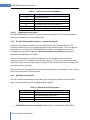
2.5.2.12
2.5.2.13
2.5.2.14
2.5.2.15
2.5.2.16
2.5.2.17
PLL Lost Lock ................................................................................................................. 16
Software Inverter Over-Current ................................................................................... 16
Grid Frequency Fault .................................................................................................... 16
Grid Voltage Fault ......................................................................................................... 16
Software Auxiliary Over-Temperature ......................................................................... 16
Calibration Error ........................................................................................................... 16
3. OZDSP3000 Hardware Interfacing .................................................................................. 16
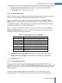
3.1
Application Interfaces................................................................................................................ 17
3.1.1 J11: SKiiP Power Module Interface – Inverter A ................................................................... 17
3.1.2 Custom Driver Interface Considerations ............................................................................... 18
3.1.2.1
Power............................................................................................................................ 19
3.1.2.2
Switch Commands ........................................................................................................ 19
3.1.2.3
Error Inputs ................................................................................................................... 19
3.1.2.4
DC Link Voltage Sensing ............................................................................................... 19
3.1.2.5
DC Link Hardware Over-Voltage Protection ................................................................. 19
3.1.2.6
Hardware Over-Current and Desaturation Protection ................................................. 19
3.1.2.7
Current Sense Signals ................................................................................................... 19
3.1.2.8
Temperature Sense Signals .......................................................................................... 20
3.1.3 J13: SKiiP Power Module Interface – Inverter B (optional) ................................................... 20
3.1.4 J8: Relay Driver Interface ...................................................................................................... 20
3.1.5 J9: Isolated Digital Inputs ...................................................................................................... 21
3.1.6 J10: Isolated Digital Outputs ................................................................................................. 21
3.1.7 J23: High Voltage Line Feedback ........................................................................................... 22
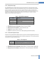
3.1.8 J25: Bias Power Input ............................................................................................................ 23
3.1.9 J4: External Temperature Input ............................................................................................ 23
3.1.10 P1: Isolated Serial Interface .................................................................................................. 24
3.1.10.1 RS232 Configuration ..................................................................................................... 24
3.1.10.2 RS422/485 Configuration ............................................................................................. 24
3.1.11 P2: Isolated CAN Bus Interface.............................................................................................. 25
3.1.11.1 J18/19 CAN Termination Jumpers ................................................................................ 25
3.2
Electrical Interfaces ................................................................................................................... 27
3.3
Mechanical Interface ................................................................................................................. 28
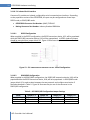
4. Parameter Register Interface ......................................................................................... 29
4.1
Register Properties .................................................................................................................... 29
4.1.1 Parameter ID ......................................................................................................................... 29
4.1.2 Data Types ............................................................................................................................. 29
4.1.2.1
Specifying Fixed-Point Parameters ............................................................................... 29
4.1.3 Access Level........................................................................................................................... 30
4.2
Volatile Registers ....................................................................................................................... 30
4.2.1 Command Registers .............................................................................................................. 30
4.2.1.1
On/Off Control .............................................................................................................. 30
4.2.1.2
Mode Control ............................................................................................................... 30
4.2.1.3
DC Link Voltage Setpoint .............................................................................................. 31
4.2.1.4
Grid Current Setpoint - Real ......................................................................................... 31
4.2.1.5
Grid Current Setpoint - Reactive .................................................................................. 31
4.2.1.6
Power Factor Setpoint .................................................................................................. 31
4.2.1.7
Fault Reset .................................................................................................................... 32
4.2.1.8
Configuration Password ............................................................................................... 32
4.2.1.9
Configuration Reset ...................................................................................................... 32
AFE Controller User’s Manual