1
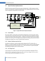
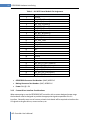
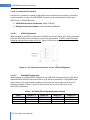
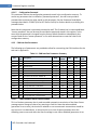
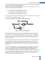
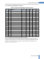
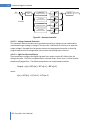
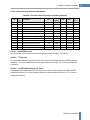
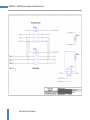
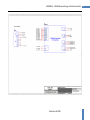
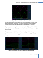
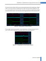
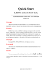
74
APPENDIX A – 100kW Reference Design and Performance Data
7.1 Overview
Oztek has developed and tested the 100kW AFE reference design shown in the schematics in
the previous section. The line filter for this design was carefully chosen based on the 100kW
power level and switching rate of 11.7 kHz.
For testing purposes, two of these AFEs were assembled and wired back-to-back to support fullload testing under various transient conditions. The sections below provide some highlights of
performance data measured with this reference design.
7.2
Current Mode Performance
The table below lists the total harmonic distortion (THD) and the total demand distortion (TDD
= THD multiplied by the ratio of the commanded current to the rated current of 120A rms)
measured when operating the 100kW AFE in current mode. These THD values were measured
using a FLUKE 434 Power Quality Analyzer. As the table illustrates, at full load the THD is
significantly lower than the typical value of 5% required by most industry standards such as
IEEE-519, UL1741, and IEEE-1547.
Table 31 – Current Mode THD
Current Level
(Arms)
10
20
30
40
50
60
70
80
90
100
110
120
THD
(%)
8.0
4.9
4.1
3.4
3.0
2.7
2.4
2.2
2.0
1.8
1.7
1.5
TDD
(%)
0.7
0.8
1.0
1.1
1.3
1.4
1.4
1.5
1.5
1.5
1.6
1.5
During the period of time that the above current mode THD measurements were made, the
measured voltage THD from the grid when the AFE was OFF was 2.6%.
Figure 23 below shows the current waveform when operating the AFE at the rated current of
120ARMS. Although not obvious, the power factor was set to 1.0 and the phase difference
between the current and voltage waveforms are due to the fact that the voltage is measured
line-to-line.
AFE Controller User’s Manual