1
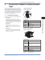
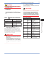
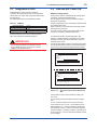
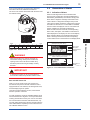
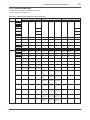
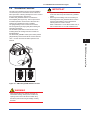
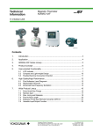
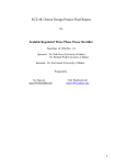
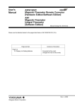
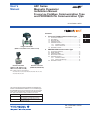
User’s Manual AXF Series Magnetic Flowmeter Installation Manual FOUNDATION Fieldbus Communication Type and PROFIBUS PA Communication Type IM 01E20A01-02EN Contents 1.FOUNDATION Fieldbus Communication Type 1.1 1.2 1.3 1.4 1.5 Integral Flowmeter (AXFG, AXFC, AXFH) Connection of Devices.....................................................1 Host Setting......................................................................2 Bus Power ON.................................................................3 Integration of DD..............................................................4 Generation of Alarm.........................................................4 1.5.1 Indication of Alarm..............................................4 1.5.2 Alarms and Events..............................................6 1.6 Simulation Function..........................................................6 2.PROFIBUS PA Communication Type 2.1 2.2 2.3 2.4 2.5 Connection of Devices.....................................................8 Master Settings................................................................9 Integration of GSD........................................................ 10 Bus and AXF Power ON................................................ 10 Generation of Alarm.......................................................11 2.5.1 Indication of Alarm............................................11 2.5.2 Alarms and Warnings...................................... 12 2.6 Simulation Function....................................................... 15 Remote Flowtube (AXFG, AXFC, AXFH, AXFW) Remote Converter (AXFA14G, AXFA14C) Note: “” means any of the following. 002, 005, 010, 015, 025, 032, 040, 050, 065, 080, 100, 125, 150, 200, 250, 300, 350, 400 This manual outlines the basic guidelines for installation procedures of the ADMAG AXF Series FOUNDATION fieldbus type and PROFIBUS PA type. For the items which are not covered in this manual, see the user’s manuals in the following table. Note: Refer to IM 01E20A01-01EN, in addition to this manual. Document No. Title IM 01E20F02-01E ADMAG AXF Series FOUNDATION Fieldbus Communication Type Magnetic Flowmeter IM 01E20F12-01E AXF PROFIBUS PA Communication Type Magnetic Flowmeter IM 01E20A01-02EN 1st Edition 1 2 1 <1. FOUNDATION Fieldbus Communication Type> 1.FOUNDATION Fieldbus Communication Type Integral Flowmeter AXF POWER SUPPLY Terminal configuration L/+ N/- Fieldbus is fully dependent upon digital communication protocol and differs in operation from conventional 4 to 20 mA transmission and the BRAIN communication protocol. It is recommended that novice users use field devices in accordance with the procedures described in this section. The procedures assume that field devices will be set up on a bench or in an instrument shop. + 1.1 Connection of Devices - FB The following are required for use with fieldbus devices: • Power supply: Terminal wiring Terminal Symbols Fieldbus requires two terminators. Refer to the supplier for details of terminators that are attached to the host. Connect fieldbus communication type AXF (Refer to Figure 1.1.1). Two or more AXF devices or other devices can be connected. Description Functional grounding •Terminator: • Field devices: FOUNDATION Fieldbus Communication Type Fieldbus requires a dedicated power supply. It is recommended that current capacity be well over the total value of the maximum current consumed by all devices (including the host). Conventional DC current cannot be used as is. 1 FA010101.ai N/– L/+ Power supply FB+ FB– Fieldbus communication signal Protective grounding (Outside of the terminal) Remote Converter AXFA14 Terminal configuration N/L/+ EX1 EX2 C SA A B SB FB+ FBFA010102.ai Terminal wiring Terminal Symbols Description EX1 EX2 Excitation current Output C SA A B SB Flow singal input Functional grounding N/– L/+ Power supply FB+ FB– Fieldbus communication signal Protective grounding (Outside of the terminal) Figure 1.1.1 Terminal Connection 1st Edition: Aug. 2015 (KP) All Rights Reserved, Copyright © 2015, Yokogawa Electric Corporation IM 01E20A01-02EN IMPORTANT CAUTION Do not connect to these terminals which are marked “CAUTION Don’t connect”. •Host: Used for accessing field devices. A dedicated host (such as DCS) is used for an instrumentation line while dedicated communication tools are used for experimental purposes. For operation of the host, refer to the instruction manual for each host. No other details on the host are given in this manual. Connecting a fieldbus configuration tool to a loop with its existing host may cause communication data scrambling resulting in a functional disorder or a system failure. 1.2 Host Setting To activate fieldbus, the following settings are required for the host. IMPORTANT •Cable: Used for connecting devices. Refer to “Fieldbus Technical Information” (TI 38K03A01-01E) for details of instrumentation cabling. For laboratory or other experimental use, a twisted pair cable two to three meters in length with a cross section of 0.9 mm2 or more and a cycle period of within 5 cm (2 inches) may be used. Termination processing depends on the type of device being deployed. For AXF, use an M4 screw terminal claw. Some hosts require a connector. Refer to Yokogawa when making arrangements to purchase the recommended equipment. Connect the devices as shown in Figure 1.1.2. Connect the terminators at both ends of the trunk, with a minimum length of the spur laid for connection. Fieldbus power supply 2 <1. FOUNDATION Fieldbus Communication Type> AXF HOST Do not turn off the power immediately after setting. When the parameters are saved to the EEPROM, the redundant processing is executed for an improvement of reliability. If the power is turned off within 60 seconds after setting is made, the modified parameters are not saved and the settings may return to the original values. Table 1.2 Operation Parameters Symbol Parameter Slot-Time Indicates the time necessary for immediate reply of the device. Unit of time is in octets (256 µs). Set maximum specification for all devices. For AXF, set a value of 4 or greater. V (MID) Minimum-Inter-PDUDelay Minimum value of communication data intervals. Unit of time is in octets (256 µs). Set the maximum specification for all devices. For AXF, set a value of 4 or greater. V (MRD) Maximum-ReplyDelay The worst case time elapsed until a reply is recorded. The unit is Slottime; set the value so that V (MRD) ×V (ST) is the maximum value of the specification for all devices. For AXF, the setting must be a value of 12 or greater. V (FUN) First-Unpolled-Node Indicate the address next to the address range used by the host. Set 0×15 or greater. V (NUN) Number-ofconsecutiveUnpolled-Node Unused address range. Terminator Terminator FA010103.ai Figure 1.1.2 Cabling Description and Settings V (ST) NOTE No CHECK terminal is used for fieldbus communication AXF. Do not connect the field indicator and check meter. Before using a fieldbus configuration tool other than the existing host, confirm it does not affect the loop functionality in which all devices are already installed in operation. Disconnect the relevant control loop from the bus if necessary. IM 01E20A01-02EN 0x00 0x0F 0x10 0x13 0x14 1.3 Bus Power ON Not used Bridge device LM device V(FUN) Unused V(FUN)+V(NUN) 3 <1. FOUNDATION Fieldbus Communication Type> V(NUN) BASIC device 0xF7 0xF8 Turn on the power of the host and the bus and also the power for the AXF. Where the AXF is equipped with an LCD indicator, first all segments are lit, then the display begins to operate. Using the host device display function, check that the AXF is in operation on the bus. The device information, including PD tag, Node address, and Device ID, is described on the sheet attached to the AXF. The device information is given in duplicate on this sheet (Refer to Figure 1.3). Default address 0xFB 0xFC 0xFF Portable device address DEVICE INFORMATION FA010201.ai Figure 1.2 Available Address Range : : : : : : 594543000BXXXXXXXX FT2001 1 0xF4 XXXXXXXXXXXXXXXXX 1 FOUNDATION Fieldbus Communication Type Note 1: Bridge device: A linking device which brings data from one or more H1 networks. Note 2: LM device: with bus control function (Link Master function) Note 3: BASIC device: without bus control function Device ID PD Tag Device Revision Node Address Serial No. Physical Location Note: Our Device Description Files and Capabilities Files available at http://www.yokogawa.com/fld (English) or http://www.yokogawa.co.jp/fld/ (Japanese) DEVICE INFORMATION Device ID PD Tag Device Revision Node Address Serial No. Physical Location : : : : : : 594543000BXXXXXXXX FT2001 1 0xF4 XXXXXXXXXXXXXXXXX Note: Our Device Description Files and Capabilities Files available at http://www.yokogawa.com/fld (English) or http://www.yokogawa.co.jp/fld/ (Japanese) FA010301.ai Figure 1.3 Device Information Sheet Attached to AXF If no AXF is detected, check the available address range. If the node address and PD tag are not specified when ordering, default value is factory set. If two or more AXFs are connected at a time with default value, only one AXF will be detected from the host as AXFs have the same initial address. Separately connect each AXF and set a different address for each. IM 01E20A01-02EN 4 <1. FOUNDATION Fieldbus Communication Type> 1.4 Integration of DD 1.5 Generation of Alarm If the host supports DD (Device Description), the DD of the AXF needs to be installed. Check if host has the following directory under its default DD directory. 594543\000B (594543 is the manufacturer number of Yokogawa Electric Corporation, and 000B is the AXF device number, respectively.) If this directory is not found, the DD of the AXF has not been included. Create the above directory and copy the DD file (0m0n.ffo, 0m0n.sym) (m, n is a numeral) into the directory. ‘0m’ in the file name shows the device revision, and ‘0n’ shows the DD revision. Once the DD is installed in the directory, the name and attribute of all parameters of the AXF are displayed. Off-line configuration is possible by using capabilities files. AXF has two capabilities levels, “1” and “2”. Select “Capabilities level = 1” when the AXF doesn’t have LC1(PID function) option. Select “Capabilities level = 2” when the AXF has LC1(PID function) option. The capabilities level defines the kind and the number of function blocks that can be used. The table below shows the relation. 1.5.1 Indication of Alarm When the self-diagnostics function indicates that a device is faulty, an alarm (device alarm) is issued from the resource block. When an error (block error) is detected in each function block or an error in the process value (process alarm) is detected, an alarm is issued from each block. If an LCD indicator is installed, the error number is displayed. If two or more alarms are issued, multiple error numbers are displayed. For details of ALARM, refer to Table 1.5.1. Upon occurrence of an alarm (example: a System alarm) Alarm name Description Countermeasure message Upon issuance of a warning (a description appears in the 3rd line only when a warning is occurred) Description of warning FA010501.ai Table 1.4 The capability level and function blocks that can be used Capabilities Level AI DI IT AR PID 1 1 2 2 1 0 2 1 2 2 1 1 Figure 1.5.1 Error Identification on Indicator If you do not have the DD or capabilities files, you can download them from our web page: http://www.yokogawa.com/fld/ IM 01E20A01-02EN 5 <1. FOUNDATION Fieldbus Communication Type> Following tables summarize the value of AXF parameters and LCD display indicates an Alarm. Table 1.5.1 Alarm Summary Category System Alarms BLOCK_ ERROR Primary Value Primary Value Status 50:Span > 10m/s 160 Other Hold BAD: Configuration Error BAD:Device Failure 51:Span < 0.1m/s 159 Other Hold BAD: Configuration Error Hold BAD:Device Failure 57:Dens Set Err 157 Other Hold Hold BAD:Device Failure BAD: Configuration Error Other Hold BAD:Sensor Failure 71:Meas Mod Set 156 Other Hold BAD: Configuration Error 194 Other Hold BAD:Device Failure 72:Size Set Err 155 Other Hold BAD: Configuration Error 100:Comm uP Fault 190 Other Variable BAD:Device Failure 73:Adh Set Err 154 Other Hold BAD: Configuration Error 101:Comm EEPROM Fault 189 Other Variable BAD:Device Failure BLOCK_ ERROR Primary Value Primary Value Status 10:uP Fault 200 Other Hold BAD:Device Failure 11:EEPROM Fault 199 Other Hold BAD:Device Failure 12:A/D (H) Fault 198 Other Hold 13:A/D (L) Fault 197 Other 14:A/D (Z) Fault 196 Other 15:Coil Open 195 16:EEPROM Dflt 102:IT1 Not Saved - 103:IT2 Not Saved - 104:Comm Error1 188 Other Variable BAD:Device Failure 105:Comm Error2 187 Other Variable BAD:Device Failure 106:DL Incomplete - 107:Download Fail - 108:Not Ready - 30:Sig Overflow 170 Other Hold BAD:Sensor Failure 31:Empty Pipe 169 Other Hold BAD:Sensor Failure 33:Adhesion Alm 167 Other Setting Alarms Alarm 120:IT1 Clock Per Err - 121:IT2 Clock Per Err - 122:AR Range Set Err - 80:Adhesion Wng 150 Other Uncertain: Sensor Conversion not Accurate 82:Auto Zero Wng 148 Other Uncertain: Sensor Conversion not Accurate 84:Disp Over Wng 85:Flow Vel Over BAD:Sensor Failure - 147 Other Uncertain: Engineering Unit Range Violation 130:AI NonSchedule - 131:IT1 NonSchedule - 110:AI Lo Lo Alm - 132:IT2 NonSchedule 111:AI Hi Hi Alm - 133:DI1 NonSchedule - 112:PID Lo Lo Alm - 134:DI2 NonSchedule - - 135:AR NonSchedule - BAD:Non-specific 136:PID NonSchedule - BAD:Out of Service 140:Sim. Jmpr On - - 141:AI Sim. Enabled - 113:PID Hi Hi Alm 40:RS O/S Mode 41:TB O/S Mode 42:AI FB O/S Mode 43:IT1 FB O/S Mode O/S Mode Alarms Hold Category Out of Service Warning - 44:IT2 FB O/S Mode 142:DI1 Sim. Enabled - - 45:DI1 FB O/S Mode 143:DI2 Sim. Enabled - 150:AI FB Man Mode - 46:DI2 FB O/S Mode - - 47:AR FB O/S Mode 151:IT1 FB Man Mode - - 48:PID FB O/S Mode 152:IT2 FB Man Mode - 153:DI1 FB Man Mode - 154:DI2 FB Man Mode - 155:AR FB Man Mode - 156:PID FB Man Mode - 160:PID FB Bypass Mode - IM 01E20A01-02EN 1 FOUNDATION Fieldbus Communication Type Process Alarms XD_ ERROR (Value) XD_ ERROR (Value) Alarm 6 <1. FOUNDATION Fieldbus Communication Type> 1.5.2 Alarms and Events 1.6 Simulation Function The following alarms or events can be reported by the AXF if Link object and VCR static entry are set. The simulation function simulates the input of a function block and lets it operate as if the data was received from the transducer block. It is possible to conduct testing for the downstream function blocks or alarm processes. A SIMULATE_ENABLE switch is mounted in the AXF amplifier. This is to prevent the accidental operation of this function. When this is switched on, simulation is enabled. (See Figure 1.6.) To initiate the same action from a remote terminal, if REMOTE LOOP TEST SWITCH is written to the SIM_ENABLE_MSG parameter (index 1044) of the resource block, the resulting action is the same as is taken when the above switch is on. Note that this parameter value is lost when the power is turned OFF. In simulation enabled status, an alarm is generated from the resource block, and other device alarms will be masked; for this reason the simulation must be disabled immediately after using this function. The SIMULATE parameter of AI and DI block consists of the elements listed in Table 1.6 below. Analog Alerts (Generated when a process value exceeds threshold) By AI BlockHi-Hi Alarm, Hi Alarm, Low Alarm, Low-Low Alarm Discrete Alerts (Generated when an abnormal condition is detected) By Resource Block Block Alarm, Write Alarm By Transducer Block Block Alarm By AI, DI, IT, AR and PID Blocks Block Alarm Update Alerts (Generated when an important (restorable) parameter is updated) By Resource Block Update Event By Transducer Block Update Event By AI, DI, IT, AR and PID Blocks Update Event An alert has following structure: Table 1.5.2 Alert Object Table 1.6 Simulate Parameter (SIMULATE/SIMULATE_D) Description Update Alert Parameters Discrete Alert Sub-index Analog Alert Subindex 1 1 1 Block Index Index of block from which alert is generated 2 Simulate Value Sets the value of the data to be simulated. 2 2 2 Alert Key Alert Key copied from the block 3 Transducer Status 3 3 3 Standard Type Type of the alert Displays the data status from the transducer block. It cannot be changed. 4 4 4 Mfr Type Alert Name identified by manufacturer specific DD 4 Transducer Value 5 5 5 Message Type Reason of alert notification Displays the data value from the transducer block. It cannot be changed. 6 6 6 Priority Priority of the alarm 5 Enable Disable 7 7 7 Time Stamp Time when this alert is first detected Controls the simulation function of this block. 1: Disable (standard) 2: Active 8 8 Subcode Enumerated cause of this alert 9 9 Value Value of referenced data 10 10 Relative Index Relative index of referenced data 8 Static Revision Value of static revision (ST_REV) of the block 9 Unit Index Unit code of referenced data 11 11 Parameter Name Explanation 1 Simulate Status Sets the data status to be simulated. When Simulate “Enable Disable” in Table 1.6 above is set to 2, the applicable function block uses the simulation value set in this parameter instead of the data from the transducer block. This setting can be used for propagation of the status to the trailing blocks, generation of a process alarm, and as an operation test for trailing blocks. IM 01E20A01-02EN <1. FOUNDATION Fieldbus Communication Type> 7 Normal Operation Simulate Enable 1 SW101 SW101 FOUNDATION Fieldbus Communication Type 1 2 ON 1 2 ON FA010601.ai Figure 1.6 SIMULATE_ENABLE Switch Position IMPORTANT • Removing and installing cover are necessary for the setting SIMULATE_ENABLE switch. Perform removing and installing cover as described in following Section of user’s manual. Refer to Subsection 5.4.2 of IM 01E20D01-01E, or refer to Subsection 10.1.2 of IM 01E20C02-01E. • To preserve the safety, do not touch the electrical circuit and cable except the SIMULATE_ENABLE switch. IM 01E20A01-02EN 8 <2. PROFIBUS PA Communication Type> 2.PROFIBUS PA Communication Type PROFIBUS PA is fully dependent upon digital communication protocol and differs in operation from conventional 4 to 20 mA transmission and the BRAIN communication protocol. Integral Flowmeter AXF Terminal configuration POWER SUPPLY - FB + Class 2 Master FieldMate (FDT/DTM) Class I Master PDM (EDDL), etc. I/O CARD, PLC, etc. L/+ N/- HMI FA020102.ai PROFIBUS-DP Terminal wiring Terminal Symbols DP/PA Coupler Description Functional grounding PROFIBUS-DP devices PROFIBUS-PA (31.25 kbps) N/– L/+ Power supply FB+ FB– PROFIBUS PA communication signal Protective grounding (Outside of the terminal) PROFIBUS-PA devices (AXF) FA020101.ai Figure 2.1.1 PROFIBUS System Construction 2.1 Connection of Devices The following are required for use with PROFIBUS PA devices: • Power supply: PROFIBUS PA requires a dedicated power supply. It is recommended that current capacity be well over the total value of the maximum current consumed by all devices. Power is supplied by a DP/PA coupler. •Terminators: PROFIBUS PA requires two terminators. A terminator shall be located at each end of the trunk cable. • Field devices: Connect PROFIBUS PA communication type AXF (Refer to Figure 2.1.2). Two or more AXF devices or other devices can be connected. Remote Converter AXFA14 Terminal configuration N/L/+ EX1 EX2 C SA A B SB FB+ FBFA020103.ai Terminal wiring Terminal Symbols Description EX1 EX2 Excitation current Output C SA A B SB Flow singal input Functional grounding N/– L/+ Power supply FB+ FB– PROFIBUS PA communication signal Protective grounding (Outside of the terminal) Figure 2.1.2 Terminal Connection IM 01E20A01-02EN 9 <2. PROFIBUS PA Communication Type> 2.2 Master Settings CAUTION Do not connect to these terminals which are marked “CAUTION Don’t connect”. • DP/PA Couplers: PROFIBUS PA requires DP/PA couplers which convert the RS-485 signals to the IEC 61158-2 signal level and power the field devices via the PROFIBUS PA. •Cable: To activate PROFIBUS PA, the following bus parameters must be set for the master. IMPORTANT Do not turn off the power immediately after setting. When the parameters are saved to the EEPROM, the redundant processing is executed for an improvement of reliability. If the power is turned off within 60 seconds after setting is made, the modified parameters are not saved and the settings may return to the original values. Refer to Figure 2.1.1. Table 2.1 PROFIBUS PA Cables and Transmissible Length Type A: Individually-shielded twisted pair cable #18AWG (0.82 mm2) 1,900 m Type B: Overall-shielded twisted pair cable #22AWG (0.32 mm2) 1,200 m Type C: Unshielded twisted pair cable #26AWG (0.13 mm2) 400 m Type D: Overall-shielded nontwisted cable #16AWG (1.25 mm2) 200 m Type of cable Note: Yokogawa recommends the use of Type A. Usage of Type B and D is restricted. Yokogawa does not recommend the use of Type C. Before using a PROFIBUS PA configuration tool other than the existing class 1 and class 2 Masters, confirm it does not affect the loop functionality in which all devices are already installed in operation. Disconnect the relevant control loop from the bus if necessary. IMPORTANT • It is mandatory to turn on the power supply of the AXF before turning on the power supply for the PROFIBUS line. • Connecting a PROFIBUS PA configuration tool to a loop with its existing class 1 and class 2 Masters may cause communication data scrambling resulting in a functional disorder or a system failure. Symbol Transmission rate Parameter Description and Settings The transmission rate of PROFIBUS PA matches that of the Transmission Rate segment coupler. e.g P+F: 93.75 kbps, Siemens: 45.45 kbps The maximum time a master station must wait for the complete reception of the first octet of a response (11 bits). e.g: 4095 TSL Slot Time min TSDR Sets the minimum time at which Min. Station Delay a slave can send the first bit of a Timer response back. max TSDR Sets the maximum time at which Max. Station Delay a slave can send the first bit of a Time response back. TQUI Quiet Time Controls the time at which the bus electronics or software of the sender is set to receive mode after a message is sent. TSET Setup Time Sets the maximum allowable time for parameter setting and response by the slave. HSA Highest Station Address Sets the highest station address in the network. G Sets the number of token cycles Gap update factor after which the master will search for a new master. max. retry limit Max Retry Limit Sets the number of retries that are performed after a receiver does not respond to a message. IM 01E20A01-02EN 2 PROFIBUS PA Communication Type Cable specifications Max. length of cable (reference value) Table 2.2 Bus Parameters 2.3 Integration of GSD A PROFIBUS PA system requires a GSD file containing device parameters such as the supported transmission rate, input data, output data, data format and data length. The following GSD files are available for the AXF. Table 2.3 GSD files Profile Ident-Number Profile GSD file 0x9740 PA139740.GSD (AIx1, TOTx1) Device Specific Ident-Number 0x4590 Device Specific GSD file 10 <2. PROFIBUS PA Communication Type> YEC_4590.GSD Download GSD for AXF from the following website. http://www.yokogawa.com/fld/doc/profibus/ IMPORTANT Do not change contents in the GSD file from the factory default. The AXF may be given a serious problem in its operation if do so. 2.4 Bus and AXF Power ON Address setting Switch A setup of bus address is possible by the change with a parameter, or the hardware slide switch. The set address which is done by hardware is higher priority than by software. Following description is how to set the bus address using by hardware slide switch. Refer to Section 5.3 of IM 01E20F12-01E when the bus address is set by software. The AXF must turn off the power supply when the bus address is changed by hardware slide switch. The device information, including Tag Desc., Bus address, and Ident Number, is described on the sheet attached to the AXF. The device information is given in duplicate on this sheet. Confirm the bus address written in the device information. The default bus address is set as 126 (hexadecimal 7E) at the factory unless otherwise specified when ordered. PROFIBUS DEVICE INFORMATION Ident Number Device Serial Number Tag Desc. Bus Address Serial Number Physical Location : 0x070D (=1805) : : : : : Note: DTM, EDD and GSD files are available on the following YOKOGAWA website: http://www.yokogawa.com/fld/doc/profibus/ PROFIBUS DEVICE INFORMATION Ident Number Device Serial Number Tag Desc. Bus Address Serial Number Physical Location : 0x070D (=1805) : : : : : Note: DTM, EDD and GSD files are available on the following YOKOGAWA website: http://www.yokogawa.com/fld/doc/profibus/ FA020401.ai Figure 2.4.1 Device Information Sheet Attached to AXF Confirm that the AXF is turned off before opening the front cover. The bus address switch is located as shown in Figure 2.4.1. The No. 8 switch of SW102 is turned ON first. Other seven switches of No. 1 to No. 7 on the SW102 are for setting address. No. 1 switch of SW102 is allocated for bit0 of address, and No. 7 switch of SW102 is allocated for bit6 of address. The setting condition of the SW102 as shown in Figure 2.4.2 is 3 as the set bus address number as an example. IM 01E20A01-02EN If two or more AXFs are connected on the same bus, each AXF must be set as different bus address. The front cover must be closed after finish the work of the bus address setting. O N ON 3 4 5 6 7 8 1 2 SW102 6 OFF 5 OFF 4 OFF 2.5.1 Indication of Alarm When the self-diagnostics function indicates that a device is faulty, a diagnostic message (DIAGNOSIS or DIAGNOSIS_EXTENSION) is issued from the physical block. When a diagnostic message is detected in each function block or a diagnostic message in the process value (process alarm) is detected, a diagnostic message is issued from each block. If a LCD indicator is installed, the error number is displayed. If two or more alarms are issued, multiple error messages are displayed. When an alarm has been occurred, the corresponding alarm name, description, and suitable countermeasure will be displayed on the display unit. The normal Display Mode and Alarm Mode may be displayed alternatively. When a warning has been issued, the corresponding content will be shown in the third line in the Display Mode. 2 OFF ADDRESS 7 OFF 2.5 Generation of Alarm 3 OFF LSB 1 ON 2 ON Upon occurrence of an alarm (example: a System alarm) Alarm name Description FA020402.ai Figure 2.4.2 Address Switch WARNING When opening the cover, wait for more than 10 minutes after turning off the power. Furthermore, opening of the cover must also be carried out by the trained personnel having knowledge of safety standard. Countermeasure message Upon issuance of a warning (a description appears in the 3rd line only when a warning is occurred) Description of warning FA020501.ai Figure 2.5 Error Identification on Indicator IMPORTANT To preserve the safety, do not touch the electrical circuit and the cables except the Bus address switch. Bus and AXF Power ON Firstly, turn on the power of the host, and then, the bus and also the power for the AXF. Where the AXF is equipped with the LCD indicator, first all segments are lit, then the display begins to operate. Using the host device display function, check that the AXF is in operation on the bus. If no AXF is detected, check the available address range. If the Bus address and Tag Desc. are not specified when ordering, default value is factory set. If two or more AXFs are connected at the same time with default value, only one AXF will be detected from the host as AXFs have the same initial address. Separately connect each AXF and set a different address for each. IM 01E20A01-02EN PROFIBUS PA Communication Type MSB 8 ON 11 <2. PROFIBUS PA Communication Type> 12 <2. PROFIBUS PA Communication Type> 2.5.2 Alarms and Warnings The alarm and warning lists in each function block are shown in Table 2.5.1 to Table 2.5.3. Table 2.5.1 Status of each parameter in failure mode (1/2) Category System Alarms Alarm 10:uP Fault 11:EEPROM Fault 12:A/D(H) Fault AI Block TOT Block FSAFE_TYPE = 0 FSAFE_TYPE = 1 FSAFE_TYPE = 2 Uncertain; Substitude Value, ok Uncertain; Last Usage Value, ok Bad; Device Failure, Const. FAIL_TOT = 0 Uncertain Non Specific, ok FAIL_TOT = 1 Uncertain; Last Usable Value, Const. DI Block FAIL_TOT = 2 Uncertain Non Specific, ok FSAFE_TYPE = 0 FSAFE_TYPE = 1 FSAFE_TYPE = 2 Uncertain; Substitude Value, ok Uncertain; Last Usage Value, ok Bad; Device Failure, Const. 13:A/D(L) Fault 14:A/D(Z) Fault 15:Coil Open Bad; Sensor Failure, Const. Bad; Sensor Failure, Const. 16:EEPROM Dflt Bad; Device Failure, Const. Bad; Device Failure, Const. 100:Comm uP Faul Bad; Device Failure, ok Bad; Device Failure, ok 101:Comm EEPROM Fault 102:Total1 Not Saved 103:Total2 Not Saved 104:Total3 Not Saved 105:Comm Error1 106:Comm Error2 Process Alarms – – – – – – – – – – – – – Uncertain; Substitude Value, ok – Uncertain; Last Usage Value, ok – Bad; Device Failure, ok – Uncertain Non Specific, ok Uncertain; Last Usable Value, Const. Uncertain Non Specific, ok Uncertain; Substitude Value, ok – Uncertain; Last Usage Value, ok 107:DL Incomplete – – – – – – – – 108:Download Fail – – – – – – – – 30:Sig Overflow 31:Empty Pipe – Bad; Device Failure, ok – – Uncertain; Substitude Value, ok Uncertain; Last Usage Value, ok Bad; Sensor Failure, Const. Uncertain Non Specific, ok Uncertain; Last Usable Value, Const. Uncertain Non Specific, ok Uncertain; Substitude Value, ok Uncertain; Last Usage Value, ok Bad; Sensor Failure, Const. Uncertain; Substitude Value, ok Uncertain; Last Usage Value, ok Bad; Sensor Failure, Const. Uncertain Non Specific, ok Uncertain; Last Usable Value, Const. Uncertain Non Specific, ok Uncertain; Substitude Value, ok Uncertain; Last Usage Value, ok Bad; Sensor Failure, Const. 32:HH/LL Alm 33:Adhesion Alm 34:Insulation Alm 110:AI Lo Lo Alm Good; Good; Good; Active Critical Active Critical Active Critical Alarm, Low limt. Alarm, Low limt. Alarm, Low limt. – – – – – – 111:AI Hi Hi Alm Good; Good; Good; Active Critical Active Critical Active Critical Alarm, High limt. Alarm, High limt. Alarm, High limt. – – – – – – AI Lo Alm Good; Good; Good; Active Advisory Active Advisory Active Advisory Alarm, Low limt. Alarm, Low limt. Alarm, Low limt. – – – – – – AI Hi Alm Good; Good; Good; Active Advisory Active Advisory Active Advisory Alarm, High limt. Alarm, High limt. Alarm, High limt. – – – – – – TOT1: Good; Active Critical Alarm, Low limt. TOT2: -TOT3: -- – – – TOT1: Good; Active Critical Alarm, Low limt. TOT2: -TOT3: -- TOT1: Good; Active Critical Alarm, Low limt. TOT2: -TOT3: -- – – – – – – TOT1: Good; TOT1: Good; TOT1: Good; Active Critical Active Critical Active Critical Alarm, High limt. Alarm, High limt. Alarm, High limt. TOT2: -TOT2: -TOT2: -TOT3: -TOT3: -TOT3: -- – – – – – – TOT1: Good; Active Advisory Alarm,Low limt. TOT2: -TOT3: -- TOT1: Good; Active Advisory Alarm,Low limt. TOT2: -TOT3: -- TOT1: Good; Active Advisory Alarm,Low limt. TOT2: -TOT3: -- – – – – – – TOT1: Good; Active Advisory Alarm,High limt. TOT2: -TOT3: -- TOT1: Good; Active Advisory Alarm,High limt. TOT2: -TOT3: -- TOT1: Good; Active Advisory Alarm,High limt. TOT2: -TOT3: -- – – – – – – TOT1: -TOT1: -TOT1: -TOT2: Good; TOT2: Good; TOT2: Good; Active Critical Active Critical Active Critical Alarm, Low limt. Alarm, Low limt. Alarm, Low limt. TOT3: -TOT3: -TOT3: -- – – – – – – TOT1: -TOT1: -TOT1: -TOT2: Good; TOT2: Good; TOT2: Good; Active Critical Active Critical Active Critical Alarm, High limt. Alarm, High limt. Alarm, High limt. TOT3: -TOT3: -TOT3: -- – – – – – – TOT1: -TOT2: Good; Active Advisory Alarm,Low limt. TOT3: -- – – – Total1 Lo Lo Alm Total1 Hi Hi Alm Total1 Lo Alm Total1 Hi Alm Total2 Lo Lo Alm Total2 Hi Hi Alm Total2 Lo Alm TOT1: -TOT2: Good; Active Advisory Alarm,Low limt. TOT3: -- TOT1: -TOT2: Good; Active Advisory Alarm,Low limt. TOT3: -- IM 01E20A01-02EN 13 <2. PROFIBUS PA Communication Type> Table 2.5.2 Status of each parameter in failure mode (2/2) Category Process Alarms Alarm AI Block TOT Block FSAFE_TYPE = 0 FSAFE_TYPE = 1 FSAFE_TYPE = 2 Total2 Hi Alm FAIL_TOT = 1 FAIL_TOT = 2 TOT1: -TOT2: Good; Active Advisory Alarm,High limt. TOT3: -- FSAFE_TYPE = 0 FSAFE_TYPE = 1 FSAFE_TYPE = 2 – – – TOT1: -TOT2: Good; Active Advisory Alarm,High limt. TOT3: -- TOT1: -TOT2: Good; Active Advisory Alarm,High limt. TOT3: -- – – – – – – TOT1: -TOT1: -TOT1: -TOT2: -TOT2: -TOT2: -TOT3: Good; TOT3: Good; TOT3: Good; Active Critical Active Critical Active Critical Alarm, Low limt. Alarm, Low limt. Alarm, Low limt. – – – – – – TOT1: -TOT1: -TOT1: -TOT2: -TOT2: -TOT2: -TOT3: Good; TOT3: Good; TOT3: Good; Active Critical Active Critical Active Critical Alarm, High limt. Alarm, High limt. Alarm, High limt. – – – – – – TOT1: -TOT2: -TOT3: Good; Active Advisory Alarm,Low limt. TOT1: -TOT2: -TOT3: Good; Active Advisory Alarm,Low limt. TOT1: -TOT2: -TOT3: Good; Active Advisory Alarm,Low limt. – – – – – – TOT1: -TOT2: -TOT3: Good; Active Advisory Alarm,High limt. TOT1: -TOT2: -TOT3: Good; Active Advisory Alarm,High limt. TOT1: -TOT2: -TOT3: Good; Active Advisory Alarm,High limt. – – – Total3 Lo Lo Alm Total3 Hi Hi Alm Total3 Lo Alm Total3 Hi Alm O/S Mode Alarms DI Block FAIL_TOT = 0 Bad; Out of Service, Const. Bad; Out of Service, Const. Bad; Out of Service, Const. Bad; Out of Service, Const. Bad; Out of Service, Const. Bad; Out of Service, Const. Bad; Out of Service, Const. Bad; Out of Service, Const. Bad; Out of Service, Const. 41:TB O/S Mode Uncertain; Substitude Value, ok Uncertain; Substitude Value, ok Uncertain; Substitude Value, ok Uncertain Non Specific, ok Uncertain Non Specific, ok Uncertain Non Specific, ok Uncertain; Substitude Value, ok Uncertain; Substitude Value, ok Uncertain; Substitude Value, ok Bad; Out of Service, Const. Bad; Out of Service, Const. 42:AI FB O/S Mode Bad; Out of Service, Const. 43:Total1 FB O/S Mode – – – – – – – – – TOT1: Bad; Out of Service, Const. TOT2: – TOT3: – TOT1: Bad; Out of Service, Const. TOT2: – TOT3: – TOT1: Bad; Out of Service, Const. TOT2: – TOT3: – – – – – – – TOT1: – TOT2: Bad; Out of Service, Const. TOT3: – TOT1: – TOT2: Bad; Out of Service, Const. TOT3: – TOT1: – TOT2: Bad; Out of Service, Const. TOT3: – – – – – – – TOT1: – TOT2: – TOT3: Bad; Out of Service, Const. TOT1: – TOT2: – TOT3: Bad; Out of Service, Const. TOT1: – TOT2: – TOT3: Bad; Out of Service, Const. – – – 46:DI1 FB O/S Mode – – – – – – DI1: Bad; Out of Service, Const. DI2: DI1: Bad; Out of Service, Const. DI2: DI1: Bad; Out of Service, Const. DI2: 47:DI2 FB O/S Mode – – – – – – DI1: – DI2: Bad; Out of Service, Const. DI1: – DI2: Bad; Out of Service, Const. DI1: – DI2: Bad; Out of Service, Const. 44:Total2 FB O/S Mode 45:Total3 FB O/S Mode Setting Alarms 50:Span > 10m/s 51:Span < 0.1m/s ok Uncertain; Substitude Value, ok Uncertain; Last Usage Value, ok Bad; Non specific, Const. Uncertain Non Specific, ok Uncertain; Last Usable Value, Const. Uncertain Non Specific, ok Uncertain; Substitude Value, ok Uncertain; Last Usage Value, ok Bad; Non specific, Const. Uncertain; Substitude Value, ok Uncertain; Last Usage Value, ok Bad; Non specific, Const. Uncertain Non Specific, ok Uncertain; Last Usable Value, Const. Uncertain Non Specific, ok Uncertain; Substitude Value, ok Uncertain; Last Usage Value, ok Bad; Non specific, Const. 56:H/L HH/LL Set 57:Dens Set Err 71:Meas Mod Set 72:Size Set Err 73:Adh Set Err 120:Total1 Unit Set Err 121:Total2 Unit Set Err 122:Total3 Unit Set Err – – – TOT1:Bad; Configuration Error, ok TOT2: – TOT3: – TOT1:Bad; Configuration Error, ok TOT2: – TOT3: – TOT1:Bad; Configuration Error, ok TOT2: – TOT3: – – – – – – – TOT1: – TOT2:Bad; Configuration Error, ok TOT3: – TOT1: – TOT2:Bad; Configuration Error, ok TOT3: – TOT1: – TOT2:Bad; Configuration Error, ok TOT3: – – – – – – – TOT1: – TOT2: – TOT3:Bad; Configuration Error, ok TOT1: – TOT2: – TOT3:Bad; Configuration Error, ok TOT1: – TOT2: – TOT3:Bad; Configuration Error, ok – – – IM 01E20A01-02EN 2 PROFIBUS PA Communication Type 40:PB O/S Mode 14 <2. PROFIBUS PA Communication Type> Table 2.5.3 Status of each parameter in warning mode Category Warning Warning 80:Adhesion Wng 81:Insu-Brk Wng 82:Auto Zero Wng 84:Disp Over Wng 85:FLow Vel Over AI Block TOT Block FSAFE_TYPE = 0 FSAFE_TYPE = 1 FSAFE_TYPE = 2 FAIL_TOT = 0 FAIL_TOT = 1 DI Block FAIL_TOT = 2 FSAFE_TYPE = 0 FSAFE_TYPE = 1 FSAFE_TYPE = 2 Good (NC); Maintenance required, ok Good (NC); Maintenance required, ok Good (NC); Maintenance required, ok Good (NC); Maintenance required, ok Good (NC); Maintenance required, ok Good (NC); Maintenance required, ok Good (NC); Maintenance required, ok Good (NC); Maintenance required, ok Good (NC); Maintenance required, ok Uncertain; Non specific, ok Uncertain; Non specific, ok Uncertain; Non specific, ok Uncertain; Non specific, ok Uncertain; Non specific, ok Uncertain; Non specific, ok Uncertain; Non specific, ok Uncertain; Non specific, ok Uncertain; Non specific, ok – Uncertain; Non specific, Low/High limt. – Uncertain; Non specific, Low/High limt. – Uncertain; Non specific, Low/High limt. – Uncertain; Non specific, Low/High limt. – Uncertain; Non specific, Low/High limt. – Uncertain; Non specific, Low/High limt. – Uncertain; Non specific, Low/High limt. – – Uncertain; Non specific, Low/High limt. Uncertain; Non specific, Low/High limt. 90:Display Sw – – – – – – – – – 140:Sim. Jmpr On – – – – – – – – – 141:PB Sim. enabled (Note1) – – – – – – – – – – – – – – – – – – – – – 142:TB VF Sim. enabled (Note1) 143:AI Sim. enabled (Note1) 144:Total1 Sim. enabled (Note1) Depend on Depend on Depend on SIMULATE.Status SIMULATE.Status SIMULATE.Status – – – – – – – – – TOT1: Depend on TOT1: Depend on TOT1: Depend on SIMULATE. SIMULATE. SIMULATE. Status Status Status TOT2: – TOT2: – TOT2: – TOT3: – TOT3: – TOT3: – – – – TOT1: – TOT1: – TOT1: – TOT2: Depend on TOT2: Depend on TOT2: Depend on SIMULATE. SIMULATE. SIMULATE. Status Status Status TOT3: – TOT3: – TOT3: – – – – – – – TOT1: – TOT1: – TOT1: – TOT2: – TOT2: – TOT2: – TOT3: Depend on TOT3: Depend on TOT3: Depend on SIMULATE. SIMULATE. SIMULATE. Status Status Status – – – – – – – – – DI1: Depend on SIMULATE. Status DI2: – DI1: Depend on SIMULATE. Status DI2: – DI1: Depend on SIMULATE. Status DI2: – – – – – – – DI1: – DI2: Depend on SIMULATE. Status DI1: – DI2: Depend on SIMULATE. Status DI1: – DI2: Depend on SIMULATE. Status 150:AI FB Man Mode – – – – – – – – – 151:Total1 FB Man Mode – – – – – – – – – 152:Total2 FB Man Mode – – – – – – – – – 153:Total3 FB Man Mode – – – – – – – – – 154:DI1 FB Man Mode – – – – – – – – – 155:DI2 FB Man Mode – – – – – – – – – 145:Total2 Sim. enabled (Note1) 146:Total3 Sim. enabled (Note1) 147:DI1 Sim. enabled (Note1) 148:DI2 Sim. enabled (Note1) Note1: Make it the condition that the hardware simulation jumper is ON. IM 01E20A01-02EN <2. PROFIBUS PA Communication Type> 2.6 Simulation Function The AXF has a simulation function and it is possible to conduct testing for the downstream function blocks or alarm processes. Following description is how to use and how to set parameters in this function. A SIMULATE_ENABLE switch is mounted in the AXF amplifier (See Figure 2.6). This is to prevent the accidental operation of this function. When the No 2 switch is ON, simulation function is enabled. The [Target Mode] in each function block must be also changed from [AUTO] to [O/S] before setting the simulation parameters. The simulation parameters in each function block including alarm set as diagnosis in the AI block are described below. The SIMULATE_ENABLE switch (No 2 switch) and the [Target Mode] in each function block must be returned “OFF” / “AUTO” when the simulation operation was finished. 15 IMPORTANT • To preserve the safety, do not touch the electrical circuit and cable except the SIMULATE_ENABLE switch. • Removing and installing cover are necessary for the setting SIMULATE_ENABLE switch. Perform removing and installing cover as described in following Section of user’s manual. Refer to Subsection 5.4.2 of IM 01E20D01-01E, or refer to Subsection 10.1.2 of IM 01E20C02-01E. 2 PROFIBUS PA Communication Type SW101 O N 1 2 SIMULATE 1 2 Simulate Enable WRITE PROTECT SIMULATE WRITE PROTECT O N Simulate Disable SW101 FA020601.ai Figure 2.6 SIMULATE_ENABLE Switch Position WARNING When opening the cover, wait for more than 10 minutes after turning off the power. Furthermore, opening of the cover must also be carried out by the trained personnel having knowledge of safety standard. IM 01E20A01-02EN 16 Revision Information Title :AXF Series Magnetic Flowmeter Installation Manual FOUNDATION Fieldbus Communication Type and PROFIBUS PA Communication Type Manual No. : IM 01E20A01-02EN Edition Date 1st Aug. 2015 Page Revised Item — New publication IM 01E20A01-02EN