1
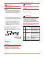
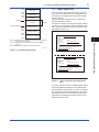
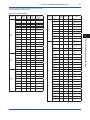
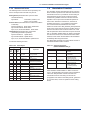
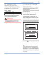
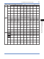
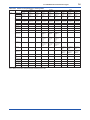
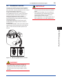
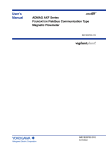
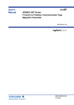
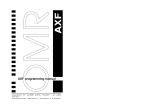
IMPORTANT
CAUTION
Do not connect to these terminals which are marked
“CAUTION Don’t connect”.
•Host:
Used for accessing field devices. A dedicated host
(such as DCS) is used for an instrumentation line
while dedicated communication tools are used for
experimental purposes. For operation of the host,
refer to the instruction manual for each host. No other
details on the host are given in this manual.
Connecting a fieldbus configuration tool to a loop
with its existing host may cause communication data
scrambling resulting in a functional disorder or a
system failure.
1.2 Host Setting
To activate fieldbus, the following settings are required for
the host.
IMPORTANT
•Cable:
Used for connecting devices. Refer to “Fieldbus
Technical Information” (TI 38K03A01-01E) for details
of instrumentation cabling. For laboratory or other
experimental use, a twisted pair cable two to three
meters in length with a cross section of
0.9 mm2 or more and a cycle period of within 5 cm
(2 inches) may be used. Termination processing
depends on the type of device being deployed. For
AXF, use an M4 screw terminal claw. Some hosts
require a connector.
Refer to Yokogawa when making arrangements to
purchase the recommended equipment.
Connect the devices as shown in Figure 1.1.2. Connect
the terminators at both ends of the trunk, with a minimum
length of the spur laid for connection.
Fieldbus power
supply
2
<1. FOUNDATION Fieldbus Communication Type>
AXF
HOST
Do not turn off the power immediately after setting.
When the parameters are saved to the EEPROM,
the redundant processing is executed for an
improvement of reliability. If the power is turned off
within 60 seconds after setting is made, the modified
parameters are not saved and the settings may return
to the original values.
Table 1.2 Operation Parameters
Symbol
Parameter
Slot-Time
Indicates the time necessary for
immediate reply of the device. Unit
of time is in octets (256 µs). Set
maximum specification for all devices.
For AXF, set a value of 4 or greater.
V (MID)
Minimum-Inter-PDUDelay
Minimum value of communication
data intervals. Unit of time is in
octets (256 µs). Set the maximum
specification for all devices. For AXF,
set a value of 4 or greater.
V (MRD)
Maximum-ReplyDelay
The worst case time elapsed until
a reply is recorded. The unit is Slottime; set the value so that V (MRD)
×V (ST) is the maximum value of the
specification for all devices. For AXF,
the setting must be a value of 12 or
greater.
V (FUN)
First-Unpolled-Node
Indicate the address next to the
address range used by the host. Set
0×15 or greater.
V (NUN)
Number-ofconsecutiveUnpolled-Node
Unused address range.
Terminator
Terminator
FA010103.ai
Figure 1.1.2 Cabling
Description and Settings
V (ST)
NOTE
No CHECK terminal is used for fieldbus
communication AXF. Do not connect the field indicator
and check meter.
Before using a fieldbus configuration tool other than
the existing host, confirm it does not affect the loop
functionality in which all devices are already installed in
operation. Disconnect the relevant control loop from the
bus if necessary.
IM 01E20A01-02EN