1
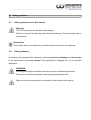
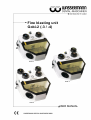
Fine blasting unit
Gobi-2 (-3 / -4)
Gobi-2
Gobi-3
Gobi-4
USER MANUAL
Dear customer,
Thank you for choosing a product from the Wassermann range. Wassermann DentalMaschinen incorporates the highest standards of quality and the latest technology.
In order to enjoy maximum performance and years of trouble-free operation, please read
this user manual carefully before you connect this device and start work, and operate the
device according to the recommended guidelines. The operation safety and the
functionality of this device can only be guaranteed if you follow both the general safety
guidelines and the applying laws to prevent accidents as well as the precautions given in
this user manual. We are not liable for any damages which occur due to inappropriate
usage or faulty operation of this device.
Make sure that anyone using this device has read and understood this user manual.
Keep this user manual in a safe place where it can be referred to as required at
any time.
Company address:
Wassermann Dental-Maschinen GmbH
Rudorffweg 15-17
D-21031 Hamburg, Germany
Phone. : +49 (0)40 / 730 926 – 0 Fax.: +49 (0)40 / 730 37 24
E-mail: [email protected]
URL: http//www.wassermann-dental.com
.
Erstellt: 19.12.2012 / msc
Version: 2
Auftrag: 190896/005
Contents
1 Features.............................................................................................................................4
2 Safety guidelines................................................................................................................5
2.1 Safety symbols used in this manual............................................................................5
2.2 Safety guidelines.........................................................................................................5
2.3 Responsibility for operation or damage.......................................................................6
3 Application..........................................................................................................................6
4 Before starting....................................................................................................................6
4.1 Transport.....................................................................................................................6
4.2 Installation...................................................................................................................7
4.3 Storage........................................................................................................................7
5 Installation / Start-up .........................................................................................................7
5.1 Assembly follow-up kit.................................................................................................9
6 Operation.........................................................................................................................12
6.1 General operating instructions..................................................................................12
7 Troubleshooting...............................................................................................................14
8 Care and maintenance.....................................................................................................15
8.1 Cleaning....................................................................................................................15
8.2 Maintenance..............................................................................................................15
8.2.1 Grip-cuff replacement.........................................................................................16
8.2.2 Screen replacement............................................................................................16
8.2.3 Conducting hose replacement............................................................................16
8.2.4 Lamp replacement..............................................................................................17
8.2.5 Nozzle replacement............................................................................................17
8.2.6 Protection filter replacement...............................................................................18
8.2.7 Water Separator.................................................................................................18
8.3 Warranty ...................................................................................................................19
8.4 Scope of delivery / Accessories................................................................................19
8.5 Spare parts................................................................................................................20
8.6 Repairs......................................................................................................................20
9 Technical data..................................................................................................................21
10 EC Conformity Certificate..............................................................................................22
1
Features
This precision fine blasting unit of the Wassermann-brand offers you the highest quality
and most advanced technology.
This 2-chamber-unit is perfect for blasting, roughing as well as blasting with specially fused
alumina. The entire system is continiously under pressure and is therefore always ready
for use. The relation between air and the blasting medium is set at the factory. It is
determined by the size of the drillings. However, the discharge velocity can be varied by
the built-in pressure reducer. The discharge velocity determines the outflowing amount of
blasting media (while the relation is kept optimal and constant).
Even when switching on the unit again, you can use the quick-start- and quick-stopfunction to begin blasting immediately. This is possible due to the crushing valve at the
conducting hose.
This unit is equipped with a socket (power consumtion: max 8 A).
■ reliable and reasonably priced fine blasting units with 2 to 4 chambers
■ quick foot-controlled start/stop function
■ precise working pressure of 1–6 bar with pressure gauge control
■ optimum illumination, protected fluorescent lamp
■ special, particularly durable hoses
■ convenient colour coding system
■ comfortably to handle with ergonomically shaped handpieces
■ hygienic changeable sleeves
■ rapid ventilation of the blasting material containers for rapid re-filling and changing of
blasting material
■ possibility to connect to suction unit
■ long durability, high flexibility
■ specially coated protection screen for ideal visibility
2
2.1
Safety guidelines
Safety symbols used in this manual
Warning!
This is a warning of risk situations and dangers.
Failure to observe this warning could be life-threatening. These warnings has to
be observed.
Information!
This symbol draws your attention to specific features that has to be observed.
2.2
Safety guidelines
Configuring and operating this equipment requires precise knowledge and observance
of the instructions in this user manual. The equipment is designed only for its intended
application.
WARNING:
Servicing and repairs should be carried out only by authorised specialists.
Disconnect the power plug before starting any maintenance work.
Make sure that the equipment is connected to the correct power source.
2.3
Responsibility for operation or damage
The responsibility for operating the device lies exclusively with the owner or user if said
device is incorrectly serviced, maintained or altered by persons not employed by an
authorised dealer or if the device is used in a manner contrary to its specified purpose.
The unit has to be maintained and operated in accordance with this user manual.
Wassermann Dental-Maschinen GmbH is not responsible for damage arising from the
nonobservance of these instructions.
Warranty and responsibility provisions contained in the sales and supply conditions of
Wassermann Dental-Maschinen GmbH are not extended by these instructions.
3
Application
This 2-chamber-blasting unit is designed for blasting, roughing as well as blasting with
specially fused alumina.
Only use the device for this type of application.
4
4.1
Before starting
Transport
Before transporting the unit, ensure that it has been unplugged from the power socket.
Make sure that it is packed correctly in order to avoid accidental damage.
Be sure to check for any transport damage when unpacking the goods. Note down
any damage if found.
6
4.2
•
Installation
Open the box, remove the packing materials, and carefully lift out the device and
accessories.
•
Avoid lifting the unit on the mounting bracket of the air control unit because it could
bend or break.
•
Avoid lifting the unit on the additional tanks because they are only suspended.
There is a risk that you break the additional tanks and the unit is dropped.
•
The device has to stand horizontally on a steady and even surface.
•
Check the included accessories.
Install the device in a place where it will not block the working area and the
functionality (take the dimensions into account).
Do not install the unit outdoors or in places without proper ventilation.
Before start-up, be sure the device reaches room temperature.
4.3
Storage
If the unit is to be stored for an extended period, protect it from moisture and dust.
5
Installation / Start-up
Before starting the unit, connect up the following:
•
Prepare a compressed air connection.
•
Furthermore an external dust-extractor should be connected.
•
The connectors are accessible from the back.
•
Finally, insert the power plug into the socket, making sure that the mains and the
unit operate on the same voltage.
7
Warning: Never connect to an oxygen bottle.
Risk of dust explosion.
Before using the unit, let it stand with open chambers until it has reached
room temperature.
•
It is absolutely necessary to switch the unit off before filling.
•
The chambers can first be screwed on when they are completely pressureless.
Press the red knob of the screwed-on cover at the right side until no outflowing air
can be heard.
All chambers are vented by pressing the according air vent knob.
•
The chamber at the right (red) will always be filled with 110-250 my material.
•
The chamber at the left (blue) will always be filled with 50-110 my material.
•
If your unit has additional tanks you can individually choose the blasting material. If
required please ask for add-on kit.
•
The chambers are only allowed to be filled up to 4 cm from the upper chamber
edge. The filling quantity shall not exceed the inside of the container located mark.
Before setting on the containers you have to assure that the threads and
sealing surfaces are free of blasting media grains.
•
Screw on the screwed-on cover properly in accordance with the colour indicator.
When all chambers have been screwed on the unit is ready for use and can be
switched on.
•
Insert the power plug firmly into the power outlet (220-240 V / 50/60 Hz).
•
Switch on the main switch (green toggle switch).
•
Set the pressure reducer to working pressure. There must be no hissing noise.
Otherwise, please retighten the screwed-on cover by hand.
8
5.1
Assembly follow-up kit
Please carry out the following preparatory measures:
•
Before you start the assembly check that the follow-up kit has been delivered
complete.
•
Unplug the Gobi-2 from its socket so that the mains supply is disconnected.
•
Remove your pressurised air connection to a safe distance and make sure that the
Gobi-2 is no longer “under pressure”.
•
In the work room remove the plug for the lead through of the steel stylus: left for the
left-hand add-on tank (yellow); right for the right-hand add-on tank (green). Figure 1
•
On the left-hand add-on tank loosen the lower screw of the electro-cover.
Only loosen, do not remove! Figure 2
Plug, right
Plug, left
Fig. 1
Only loose the
screw, do not
remove
Fig. 2
9
Now you are ready to begin the following assembly tasks:
•
Screw the screws delivered with the add-on tank loosely into position in the casing
of the Gobi-2. Figure 3 and 4
•
Now hook in the add-on tank onto the screw. Please take special care to see that
on all three of the hook-in drillings the screw heads are flush. The “wing” of the tank
retaining plate must be pushed underneath the screw which is inserted in a
sideways position. Figure 5
Fig. 3
Fig. 4
The “wing” of the tank
retaining plate must be
pushed underneath the
screw.
Fig. 5
10
•
All accessible screws are now to be screwed in tight.
•
Push the steel stylus into the work cabin through the hole in the casing.
•
Close the hole with the lead-through grommet thereby fixing the steel stylus. Take
care to lay the steel hose with a slight curve and don’t let it buckle.
•
Through the work cabin remove the indicator window and take out the lamp.
•
In each case remove the appropriate connection plug by pressing down the ring of
the plug screw-joint, at the same time pulling on the connection plug. Figure 6.
Remove the
pulling down
appropriate
the
connection
connection
plug screw-
plug
joint
Fig. 6
11
With the help of the PA-hose (320023) connect the ball cock with the squeezing
•
valve.
•
Fix the lamp back in and then the cover.
•
On the back remove the connection plug on the air current unit, there also by
pressing down the ring of the plug screw-joint and at the same time pulling on the
connection plug. Tip: try pressing the ring down with the assistance of a slotted
screwdriver. Figure 7
Remove the appropriate
connection plug screw-joint
Pulling down the
connection plug
Fig. 7
•
With the help of the PU-hose (320054) connect the air current unit with the blasting
material container.
•
Please take care that the blasting hoses run along under the sieve grille and that
the blasting protector is mounted.
6
6.1
Operation
General operating instructions
All instructions for using the unit, whether in verbal or written form, are based on our own
experience and experimentation and can only be regarded as guidelines.
12
1. Turn on main switch (green toggle switch).
2. Set the working pressure at the desired level on the reducing valve (at least 2.3 bar
at most 6 bar).
3. Designate the blasting material container by using the selection switch built-in in the
work room. If you do not possess any add-on tanks, then the green and yellow
settings will not perform any functions. Do NOT select them, since this can lead to
complications.
4. According to the colour selected, take the appropriate stylus in your hand.
5. Trigger the blasting process with the foot control.
Working is only allowed with the blasting chambers closed.
Please wear safety goggles!
Due to the operating condition, the amount of blasting media flow
may
change when the blasting media amount decreases.
By shortly tilting the unit it is possible to continue working for a short time.
However, this is an indication that you have to refill blasting media.
Female connector power consumption max: 8 A
13
7
Troubleshooting
Fault
Cause
Irregular flow of blasting Too little blasting material in
material
container
Jet on stylus too small
Blasting material is moist
No flow of blasting
material
Container empty
Main jet and/or steel hose
blocked
Decreasing and/or to
low blasting pressure
Wrong selection of colour
circuit setting
Ancillary jet blocked
Too little pressurised air
< 3 bar
Filter blocked and/or
buckled closed
Remedy
Re-fill the container
Use larger jet
Use blasting material of correct
dryness
Re-fill the container
Use recommended, dry blasting
material. Unscrew jet on the
stylus. Trigger blasting process.
Blasting material should flow. If
necessary, briefly hold the hose
closed to build up some counterpressure.
Please switch to the correct
colour circuit setting
Refer above
Increase pressure
Change filter element
If the above recommendations do not solve the problem, contact your dental depot
or our service department.
Remarks:
Obstructions normally occur from soiled or lumply blasting medium. If the sand draws
moisture, check the condensator.
Most obstructions occur inside the nozzle. To remove such obstructions unscrew the
nozzle and clean it. In general this would be sufficient to make the stuck grains come
loose. If the obstruction persists, use a needle and push it through the hole.
14
8
Care and maintenance
8.1
Cleaning
Disconnect the power plug before starting any maintenance work.
The identification plate has always to be kept in easily legible condition and has
not to be removed.
Remove external dirt from time to time with some form of cold cleaner.
Use only cold cleaners to avoid damaging the paintwork or removing the lettering.
The equipment should be cleaned at regular intervals to ensure trouble-free operation.
It requires only normal cleaning (sponge, damp cloth, mild detergent) and no further
chemical additives.
•
The inside of the chambers and the protection screens can be cleaned with
compressed air. Fine-dust will be sucked out by the dust-extractor.
•
Never use strong and abrasive solvents for cleaning the screens.
•
Coarse-grained sand, which cannot be sucked out by the dust-extractor can be
removed through the discharge opening.
8.2
Maintenance
This unit does not require any special maintenance. Just make sure that the device is kept
clean.
However, after using the unit a certain time, it will be necessary to replace some parts.
Please take care of the following parts:
15
8.2.1
Grip-cuff replacement
Cuffs can also be replaced with gloves. The procedure is the same.
•
Loosen the connector with pliers and unscrew the throughgrip (4 screws).
•
Pull off the old cuff and put on the new one so that it completely covers the opening.
•
Attach the new connector. Take care that the closing of the connector is placed
inside the notch of the opening.
•
Tighten the opening.
8.2.2
Screen replacement
•
Open the flap and loosen the five knurled nuts.
•
Remove the guide rail
•
Fold the screen to the front and pull it out. Please take care of the spacer reels.
•
Replace the screen and reassemble everything in reverse order.
8.2.3
Conducting hose replacement
Before changing, the mains plug must be disconnected and the pressurised air connection
detached.
The pressure of all the tanks must be released (cf. Installation / Start-up).
•
Take sieve unit out of the chamber.
•
Lay the appliance on its side so that you have access to the bottom of the
appliance.
•
In order to detach from the tank the blasting material hose in question, loosen the
black nut with a no. 17 spanner, then take it, and subsequently the hose too, off.
•
Pull and/or lever the silver handle on the squeezing valve, with the other hand
pulling the hose through the through-put and into the interior.
•
Remove hose protection.
16
•
In principle the installation takes place exactly in the reverse manner. The hose is
pushed from the interior of the chamber through the hole on the squeezing valve,
led through it again and pushed onto the nipple of the tank (don’t forget the nut and
the plastic cap!). Before the nut is tightened the fabric must be completely pulled
over the rubber. Should this be difficult to achieve then push the fabric outwards
from the stylus right to the end until enough fabric is available.
•
The nut can then be completely tightened (not with force! Don’t overturn it!).
•
The small hose is only to be pushed in up to the squeezing valve. The hose should
be sandwiched in between both of the styluses. It serves as a protection for the
blasting hose.
•
Put the appliance back in an upright position and re-install the sieve grille. Please
take care that the blasting hoses run along under the sieve grille and that the hose
protector is mounted.
8.2.4
Lamp replacement
Before changing it you must pull out the mains plug. The lamp is behind the indicator
window.
•
Loosen knurled nuts and take off the indicator window.
•
Pull the lamp towards the right out of its socket and in re-placing make sure that the
new lamp fits correctly back into the socket.
•
Put back the indicator window and tighten the screws.
8.2.5
Nozzle replacement
Take care that the nozzle always corresponds to the size of the used blasting medium.
The replacement is very easy. Simply unscrew the old nozzle and screw on a new one.
Important: Before setting up a new nozzle, shortly operate the unit and blow away old
blasting medium which may remain inside the hose.
17
8.2.6
Protection filter replacement
After some time of usage the filter inlet may become clogged. This filter is located in an
aluminum housing (transition piece) directly at the blasting material container.
•
Loose the nut at the container with a 17mm wrench.
•
Press down lightly the ring inside the connection and remove the hose
•
Unscrew and remove the connection.
•
Unscrew and remove the transition piece from the blasting material container with
the help of suitable tools.
•
Change the transition piece and screw it back into the blasting material container.
•
Screw the connection.
•
Reconnect the air tube.
8.2.7
Water Separator
A water separator, that absorbs any condensation coming out of the compressor, is
situated at the back of the unit. It must be checked regularly and at the latest when the
max. level is reached, it must be emptied. To do this, press the yellow discharge lever up
so that the water can flow into the container you have placed under the unit.
Remarks:
Obstructions normally occur from soiled or lumply blasting medium. If the sand draws
moisture, check the condensator.
Most obstructions occur inside the nozzle. To remove such obstructions unscrew the
nozzle and clean it. In general this would be sufficient to make the stuck grains come
loose. If the obstruction persists, use a needle and push it through the hole.
18
8.3
Warranty
The warranty period for our equipment is 12 months. If faults occur within the
warranty period, contact your dental depot or get in touch directly with our service
department.
Your equipment should only be operated in perfect condition. If faults occur which
could harm operators or third parties, the unit should not be used until it has been
fixed.
This warranty does not cover damage caused by improper use, external mechanical
causes, transport damage or interference with the unit by unauthorized persons.
8.4
Scope of delivery / Accessories
Incl. in delivery
PVC hose Ø 8x6 textile (blue) 2 m
Supply line
Gobi-2 incl. 2 fine blasting nozzles, 0.8 (blue), 1.2 (red)
Gobi-3 incl. 3 fine blasting nozzles, 0.8 (blue), 1.2 (red) and
optionally additional tank, left with fine blasting nozzle 0.6
(yellow) or 0.8 (green)
Gobi-4 incl. 4 fine blasting nozzles, 0.8 (blue), 1.2 (red) and
additional tank, left with fine blasting nozzle 0.6 (yellow) and
additional tank, right with fine blasting nozzle 0.8 (green)
Item no.:
320026
592012
190896
190896 +
item no.
additional tank
190896 +
190800 +
190802
Accessories
PVC hose Ø 8x6 textile (blue) per meter
Additional tank, left with fine blasting nozzle 0.6 mm (yellow)
Additional tank, right with fine blasting nozzle 0.8 mm (green)
Spare fine blasting nozzle 0.6 mm
Spare fine blasting nozzle 0.8 mm
Spare fine blasting nozzle 1.2 mm
Item no.:
320026
190800
190802
190550
190551
190552
We recommend the use of Wassermann blasting materials and our suction unit
SG-10/SG-20 or WTS-1R. This units work effectively and provides large filtering
capacity.
19
Summary nozzles and blasting materials
Item no.
190550
190551
190552
Name of the item
Fine blasting nozzle 0,6 mm
Fine blasting nozzle 0,8 mm
Fine blasting nozzle 1,2 mm
190565
Nozzle for blasting material container > 110 my
2,0 mm
(for 1,2 mm blasting nozzle)
Nozzle for blasting material container < 110 my
1,4 mm
(for 0,6 / 0,8 mm blasting nozzle)
190566
8.5
Blasting material
50 my
110/125 my + 50 my Glass beads
250 my + 110 my Glass beads
Spare parts
If necessary please contact our service hotline phone:
0049 (0)40 / 730 92 6-0
8.6
Repairs
Servicing or repairs to the unit has only to be carried out by qualified technicians.
Only original spare parts are to be used. Responsibility for the product is voided
if unauthorised persons alter it or if inappropriate components are installed.
20
9
Technical data
Gobi 2
Voltage*
Power consumption
Female connector power consumption max.
Output
WxHxD
Weight
Tank capacity
Compressed air connection
Working pressure
Extractor nozzle
Item no.: 190896
220–240 V / 50/60 Hz
0.2 A
8A
50 W
430 x 350 x 530 mm
17.5 kg
800 cm3 = 1.2 kg
3–6 bar
1–6 bar
75 mm
*Other voltages on request.
The noise level of the unit amounts to ≤ 70 dB (A).
The technical data are subject to change without prior notice.
21
10
EC Conformity Certificate
in accordance with 2006/95/EG (low-voltage guidelines) and 2004/108/EG (EMV
guidelines) and 2006/42/EG (machinery guidelines)
Manufacturer:
WASSERMANN
Dental-Maschinen GmbH
Rudorffweg 15 - 17
D-21031 Hamburg
Product description:
Model:
GOBI 2 with 2 blasting material containers
GOBI 3 with 3 blasting material containers*/**
GOBI 4 with 4 blasting material containers*&**
*additional tank right (Item no. 190802)
**additional tank left (Item no. 190800)
Applicable
standards:
DIN EN 61010-1
DIN EN 61000-6-3
DIN EN 61000-6-1
DIN 45635-1
DIN EN 60335-1
Fine blasting unit
for dental
applications
Item no. 190896
Hiermit wird bestätigt, dass die oben bezeichnete Maschine den genannten EG-Richtlinien
entspricht. Diese Erklärung wird ungültig, falls die Maschine ohne unsere Zustimmung
verändert wird.
This is to confirm that the above mentioned machine complies with the described EC
rules. This declaration becomes invalid if the machine is modified without our approval.
Cette machine est conforme aux normes en vigueur de la Communité Européene. Cet
avis est nul et non avenant si cette machine est modifiée sans notre accord.
Esta máquina, anteriormente mencionada, cumple con los limites requeridos por el
reglamento EC. Ahora bien, esta declaración quedará invalidada en caso de realizar
modificaciones al aparato sin nuestra aprobación.
Hiermee wordt bevestigd dat bovengenoemde machine voldoet aan de voorgeschreven
EU normen. Deze verklaring verliest geldigheid als er zonder onze uitdrukkelijke
toestemming wijzigen aan de machine worden aangebracht.
Place, date: Hamburg, 19.12.2012
Company stamp:
Signature: ________________________
Wilfried Wassermann
(Managing Director)
22
Notes:
23