Download SCOS-2000 Database Import ICD
Transcript
ESA/OPS-GIC SCOS-2000 Database Import ICD Document Reference: EGOS-MCS-S2K-ICD-0001 Document Status: Version 6.9 Prepared By: SCOS-2000 Team Date: 2010-07-06 Ref.: SCOS-2000 Database Import ICD Name Prepared by: SCOS-2000 Team Verified by: SCOS-2000 R5.3 Team S. Lodiot, Users Representative Approved by: Sylvie Haag, SCOS Maintenance TO Authorised by: M.Pecchioli, OPS-GIC Management Distribution List OPS-GIC ESA/OPS-GI, OPS-GD, TEC-SW, OPS-O SCOS-2000 Industry Team SCOS-2000 Document Library ESA/OPS-GIC EGOS-MCS-S2K-ICD-0001 Issue: 6. 9 Date: 2010-07-06 Page: ii Date Signature Digitally signed by Sylvain Lodiot Date: 2010.08.09 09:17:00 +02'00' Sylvie Haag Digitally signed by Sylvie Haag DN: cn=Sylvie Haag, o=ESA, ou=OPSGIC, [email protected], c=DE Date: 2010.08.06 18:10:16 +02'00' Digitally signed by Mauro Pecchioli Date: 2010.08.09 10:02:08 +02'00' EGOS-MCS-S2K-ICD-0001 Ref.: SCOS-2000 Database Import ICD Issue: 6. 9 Date: 2010-07-06 Page: iii © COPYRIGHT EUROPEAN SPACE AGENCY, 2010 The copyright of this document is vested in European Space Agency. This document may only be reproduced in whole or in part, stored in a retrieval system, transmitted in any form, or by any means electronic, mechanical, photocopying, or otherwise, with the prior permission of the owners. DOCUMENT CHANGE LOG Issue/ Date Modification Nb Modified pages Observations Revision 3.2 12/03/99 All First official issue for SCOS-2000. Conversion into Microsoft Word (internal 3.3 09/07/99 All distribution only) Many editorial changes plus some noneditorial changes as listed in Annex 1 of this 4.0 29/10/99 All 4.1 20/12/99 See change bars document. Updates required to clarify the actual implementation. See Annex 1 for a complete list of implemented change requests. 4.2 01/12/00 See change bars Updates required to clarify the actual implementation. Modifications describing the changes introduced in R2.2. See Annex 1 for a complete list of implemented DCRs. ESA/OPS-GIC EGOS-MCS-S2K-ICD-0001 Ref.: SCOS-2000 Database Import ICD 5.0 02/04/01 See change bars Issue: 6. 9 Date: 2010-07-06 Page: iv Updates required to clarify the actual implementation. Modifications describing the changes introduced in SCOS-2000 R.2.2e (mainly related to the addition of the SCOS2000 Packetiser). See Annex 1 for a complete list of implemented Document Changes. 5.1 26/10/01 See change bars Updates required to clarify the actual implementation. Modifications describing the changes introduced in SCOS-2000 R.2.3 (which will be implemented in R3.0) as well as the specific additions implemented in the evolution version for EGSE systems. 5.2 2/07/03 See Annex 1 See change bars Updates required to clarify the actual implementation (see Annex 1) 6.0 17/01/05 See Annex 1 See tracked Issue applicable to SCOS R4.0. Clarifications changes (tracked of the existing implementation and updates from version 5.2) required for supporting the extensions delivered as part of S2K-R4.0 and EGSE R3.1 (see Annex 1). Backwards compatibility with databases compatible with S2K-R3.1 is preserved. 6.1 10/01/06 See Annex 1 See tracked Additional clarifications added (see Annex 1) changes (tracked from version 5.2) 6.2 01/08/06 See description of Issue applicable to SCOS R4.1. Merged 4.0.1 field PCF_USCON and S2K-3.1_M-04 baselines. 6.3 12/02/07 See Annex 1. Included indication of Document Updates in Annex 1. These were missing in version 6.2. ESA/OPS-GIC Ref.: SCOS-2000 Database Import ICD 6.4 07/03/07 See Annex I See change bars EGOS-MCS-S2K-ICD-0001 Issue: 6. 9 Date: 2010-07-06 Page: v Issues applicable to SCOS R5 (see Annex 1). Moved TC Sequence and TM display definitions out of POST MIB database to FARC as XML files. Added SLE TE command type. Modifications related to SCRs implemented in SCOS R5. 6.5 14/12/07 See Annex I See change bars Updates introduced for SCOS R4.2 and 5.0.1 (see Annex 1). 6.6 6.7 See Annex 1 01/12/09 See Annex I Updates introduced for R4.5 and R5.2.0i1 (see Annex 1)Updated for NCR-5711. Draft A Updated for SPR 4911. Udpate of approval table. 6.7 20/02/2010 See Annex I Draft ICD version with updates introduced for R4.5 and R5.2 Updated for SCR-3774 due to Draft B DCR-6008 6.7 24/05/2010 Draft C See Annex I Draft ICD version with Uupdates introduced for R5.3.1. SPR 5504 about dynamic changes to TPSD. ESA/OPS-GIC Ref.: SCOS-2000 Database Import ICD 6.9 06/07/2010 See Annex I EGOS-MCS-S2K-ICD-0001 Issue: 6. 9 Date: 2010-07-06 Page: vi Final ICD applicable to S2K53, S2K531, S2k54. This is a consolidated version applicable merging changes done in several SCOS releases in parallel (s2k52, s2k53, s2k531, s2k4.51) - update of fields CVE_CVSID, CVP_CVSID - update of reference documents See annex 1 ESA/OPS-GIC EGOS-MCS-S2K-ICD-0001 Ref.: SCOS-2000 Database Import ICD Issue: 6. 9 Date: 2010-07-06 Page: vii PAGE ISSUE RECORD Issue of this document comprises the following pages at the issue shown Page Issue/ Revision ESA/OPS-GIC Page Issue/ Revision Page Issue/ Revision Page Issue/ Revision Page Issue/ Revision Ref.: SCOS-2000 Database Import ICD EGOS-MCS-S2K-ICD-0001 Issue: 6. 9 Date: 2010-07-06 Page: viii Abstract This document is the interface control document of the data import into SCOS-2000 run-time database. Data in the suitable format are typically generated by the off-line database management system of any client mission using SCOS-2000. This document only covers the ‘generic’ portion of the static database which are relevant to SCOS-2000 functions. Mission specific extensions are possible. ESA/OPS-GIC Ref.: SCOS-2000 Database Import ICD EGOS-MCS-S2K-ICD-0001 Issue: 6. 9 Date: 2010-07-06 Page: ix TABLE OF CONTENTS Abstract.......................................................................................................................................................................viii List of Figures ............................................................................................................................................................. xiv List of Tables .............................................................................................................................................................. xiv 1 Introduction............................................................................................................................................................ 1 1.1 PURPOSE ......................................................................................................................................................... 1 1.1 SCOPE ............................................................................................................................................................. 1 1.2 OVERVIEW ...................................................................................................................................................... 1 1.3 DEFINITIONS, ACRONYMS AND ABBREVIATIONS ............................................................................................ 3 1.3.1 Definitions and Terminology.................................................................................................................. 3 1.3.2 Acronyms and Abbreviations ................................................................................................................. 3 1.4 2. 3. REFERENCES ................................................................................................................................................... 4 1.4.1 Applicable documents ............................................................................................................................ 4 1.4.2 Reference documents.............................................................................................................................. 5 Interface overview.................................................................................................................................................. 7 2.1 ASSUMPTIONS AND CONSTRAINTS .................................................................................................................. 7 2.2 LOCATION AND NAMING CONVENTION OF THE ASCII FILES .......................................................................... 7 2.3 STRUCTURE OF THE ASCII FILES .................................................................................................................... 8 2.4 CHECKS APPLIED AT IMPORT TIME ................................................................................................................. 8 2.5 IMPORT OPTIONS ............................................................................................................................................ 9 Detailed Interface Specification ........................................................................................................................... 11 3.1 RELATIONSHIP BETWEEN THE ASCII TABLES AND THE DATABASE ITEMS ................................................... 11 3.2 SUMMARY OF THE ASCII TABLES ................................................................................................................. 16 3.3 DETAILED DEFINITION OF THE ASCII TABLES STRUCTURE .......................................................................... 21 3.3.1 General................................................................................................................................................. 23 3.3.1.1 3.3.2 Database version: vdf ........................................................................................................................................23 Monitoring Data................................................................................................................................... 24 3.3.2.1 ESA/OPS-GIC Monitoring Parameters ......................................................................................................................................25 Ref.: SCOS-2000 Database Import ICD EGOS-MCS-S2K-ICD-0001 Issue: 6. 9 Date: 2010-07-06 Page: x 3.3.2.1.1 Monitoring parameters characteristics: pcf..................................................................................................25 3.3.2.1.2 Synthetic parameters....................................................................................................................................40 3.3.2.1.3 User Defined Constants ...............................................................................................................................43 3.3.2.1.4 Dynamic Configuration Variables ...............................................................................................................45 3.3.2.1.5 System Control Parameters..........................................................................................................................47 3.3.2.2 Monitoring parameters calibration.....................................................................................................................47 3.3.2.2.1 Calibration conditional selection: cur ..........................................................................................................48 3.3.2.2.2 Numerical calibrations: caf..........................................................................................................................50 3.3.2.2.3 Numerical calibrations definition: cap.........................................................................................................52 3.3.2.2.4 Textual calibrations: txf...............................................................................................................................53 3.3.2.2.5 Textual calibrations definition: txp..............................................................................................................54 3.3.2.2.6 Polynomial calibrations definitions: mcf .....................................................................................................55 3.3.2.2.7 Logarithmic calibrations definitions: lgf......................................................................................................56 3.3.2.3 Monitoring parameter checks ............................................................................................................................57 3.3.2.3.1 Monitoring checks: ocf ................................................................................................................................57 3.3.2.3.2 Monitoring checks definition: ocp ...............................................................................................................59 3.3.2.4 Telemetry Packets Definition ............................................................................................................................65 3.3.2.4.1 Packets identification: pid............................................................................................................................66 3.3.2.4.2 Packets identification criteria: pic................................................................................................................75 3.3.2.4.3 Telemetry packets characteristics: tpcf ........................................................................................................77 3.3.2.5 Telemetry Packets Processing ...........................................................................................................................80 3.3.2.5.1 Parameters location in fixed packets: plf .....................................................................................................81 3.3.2.5.2 Variable packet definition: vpd....................................................................................................................84 3.3.2.6 Monitoring Groups ............................................................................................................................................92 3.3.2.6.1 Monitoring groups definition: grp ...............................................................................................................92 3.3.2.6.2 Parameters groups: grpa ..............................................................................................................................93 3.3.2.6.3 Telemetry packets groups: grpk...................................................................................................................93 3.3.2.7 Displays and reports ..........................................................................................................................................94 3.3.2.7.1 Alphanumeric displays: dpf .........................................................................................................................94 3.3.2.7.2 Alphanumeric displays definition: dpc ........................................................................................................95 3.3.2.7.3 Graphic displays: gpf...................................................................................................................................98 ESA/OPS-GIC Ref.: SCOS-2000 Database Import ICD EGOS-MCS-S2K-ICD-0001 Issue: 6. 9 Date: 2010-07-06 Page: xi 3.3.2.7.4 Graphic displays definition: gpc ................................................................................................................100 3.3.2.7.5 Scrolling displays: spf ...............................................................................................................................104 3.3.2.7.6 Scrolling displays definition: spc...............................................................................................................105 3.3.2.7.7 Printout proforma: ppf ...............................................................................................................................107 3.3.2.7.8 Printout proforma definition: ppc ..............................................................................................................108 3.3.3 Commanding data .............................................................................................................................. 110 3.3.3.1 Packet Headers ................................................................................................................................................112 3.3.3.1.1 Packet headers characteristics: tcp.............................................................................................................112 3.3.3.1.2 Packet headers parameters: pcpc ...............................................................................................................112 3.3.3.1.3 Packet headers definition: pcdf..................................................................................................................113 3.3.3.2 Commands.......................................................................................................................................................115 3.3.3.2.1 Command characteristics: ccf....................................................................................................................115 3.3.3.2.2 Command parameters: cpc ........................................................................................................................124 3.3.3.2.3 Commands definition: cdf .........................................................................................................................132 3.3.3.2.4 Commands pre-transmission validation: ptv..............................................................................................140 3.3.3.3 Command Sequences.......................................................................................................................................142 3.3.3.3.1 Command sequence characteristics: csf.....................................................................................................145 3.3.3.3.2 Command sequences definition: css ..........................................................................................................148 3.3.3.3.3 Command sequence element parameters: sdf ............................................................................................159 3.3.3.3.4 Command sequence formal parameters: csp..............................................................................................164 3.3.3.4 Verification......................................................................................................................................................170 3.3.3.4.1 Verification stages file: cvs .......................................................................................................................171 3.3.3.4.2 Verification expressions: cve.....................................................................................................................173 3.3.3.4.3 Verification profiles: cvp...........................................................................................................................178 3.3.3.5 Command/Sequence Parameter Sets ...............................................................................................................179 3.3.3.5.1 Parameter sets: pst .....................................................................................................................................180 3.3.3.5.2 Parameter value sets: psv...........................................................................................................................180 3.3.3.5.3 Parameter sets definition: cps ....................................................................................................................180 3.3.3.5.4 Parameter value sets definition: pvs ..........................................................................................................181 3.3.3.5.5 Parameter sets mapping to commands/sequences: psm .............................................................................183 3.3.3.6 ESA/OPS-GIC Command/Sequence Parameters (De-)calibrations..........................................................................................184 Ref.: SCOS-2000 Database Import ICD EGOS-MCS-S2K-ICD-0001 Issue: 6. 9 Date: 2010-07-06 Page: xii 3.3.3.6.1 Numerical (de-)calibration curves: cca ......................................................................................................184 3.3.3.6.2 Numerical (de-)calibration curves definition: ccs......................................................................................186 3.3.3.6.3 Textual (de-)calibrations: paf.....................................................................................................................187 3.3.3.6.4 Textual (de-)calibrations definitions: pas ..................................................................................................188 3.3.3.7 Command/Sequence Parameters Range Checks..............................................................................................188 3.3.3.7.1 Parameter range sets: prf ...........................................................................................................................189 3.3.3.7.2 Parameter range values: prv.......................................................................................................................191 Appendix A – SCOS-2000 Parameter Types ............................................................................................................. 192 Appendix B – SCOS-2000 Database Import Tables Overview ................................................................................. 206 Appendix C – SCOS-2000 Support of Packet Utilisation Standard (PUS)................................................................ 211 1. Support of PUS Data Types ............................................................................................................................... 212 2. Support of PUS Data Structures......................................................................................................................... 213 3. Specific Support of TM/TC Services ................................................................................................................. 214 3.1 SERVICE 1: TELECOMMAND VERIFICATION SERVICE ................................................................................... 214 3.2 SERVICE 2: DEVICE COMMAND DISTRIBUTION SERVICE .............................................................................. 214 3.3 SERVICE 3: HOUSEKEEPING AND DIAGNOSTIC DATA REPORTING SERVICE .................................................. 215 3.4 SERVICE 4: PARAMETER STATISTICS REPORTING SERVICE .......................................................................... 216 3.5 SERVICE 5: EVENT REPORTING SERVICE ...................................................................................................... 216 3.6 SERVICE 6: MEMORY MANAGEMENT SERVICE ............................................................................................ 216 3.7 SERVICE 8: FUNCTION MANAGEMENT SERVICE ........................................................................................... 217 3.8 SERVICE 9: TIME MANAGEMENT SERVICE ................................................................................................... 217 3.9 SERVICE 11: ON-BOARD OPERATIONS SCHEDULING SERVICE ...................................................................... 217 3.10 SERVICE 12: ON-BOARD MONITORING SERVICE .......................................................................................... 218 3.11 SERVICE 13: LARGE DATA TRANSFER SERVICE ........................................................................................... 219 3.12 SERVICE 14: PACKET FORWARDING CONTROL SERVICE .............................................................................. 219 3.13 SERVICE 15: ON-BOARD STORAGE AND RETRIEVAL SERVICE ...................................................................... 219 3.14 SERVICE 17: TEST SERVICE ......................................................................................................................... 220 3.15 SERVICE 18: ON-BOARD OPERATIONS PROCEDURE SERVICE ....................................................................... 220 3.16 SERVICE 19: EVENT-ACTION SERVICE ......................................................................................................... 220 ESA/OPS-GIC Ref.: SCOS-2000 Database Import ICD EGOS-MCS-S2K-ICD-0001 Issue: 6. 9 Date: 2010-07-06 Page: xiii Annex 1 – List of implemented Document Changes ................................................................................................. 221 ESA/OPS-GIC Ref.: SCOS-2000 Database Import ICD EGOS-MCS-S2K-ICD-0001 Issue: 6. 9 Date: 2010-07-06 Page: xiv List of Figures Figure 1. - Relationships for the Monitoring Tables 206 Figure 2. - Relationships for the Display tables 207 Figure 3. - Relationships for the Command tables 207 Figure 4. - Relationships for the Command Sequence tables 208 Figure 5. - Relationships for the Parameter Set tables 209 Figure 6. - Relationships for the Command and Sequence Parameter tables 210 List of Tables Table 1 - Summary of Monitoring related data............................................................................................................ 13 Table 2 - Summary of Displays related data ................................................................................................................ 14 Table 3 - Summary of Commanding related data ........................................................................................................ 16 Table 4 - Parameter Type and Format Codes supported by SCOS-2000 ................................................................... 201 Table 5 - Value formats for the SCOS-2000 parameter types.................................................................................... 205 ESA/OPS-GIC Ref.: SCOS-2000 Database Import ICD 1 EGOS-MCS-S2K-ICD-0001 Issue: 6. 9 Date: 2010-07-06 Page: 1 INTRODUCTION 1.1 PURPOSE This document is the interface control document of the data import into the SCOS-2000 run-time database. Data in the suitable format are typically generated by the off-line database management system of client missions using SCOS-2000. 1.1 SCOPE This document describes how a client mission using the SCOS-2000 system (later referred as client mission) has to present its data so that it can be imported by the SCOS-2000 system (referred as SCOS-2000 in the document). This document only covers the ‘generic’ portion of the static database which are relevant to SCOS-2000 functions. Mission specific extensions are possible. The SCOS-2000 client mission MIB static data are typically imported/activated as follows: the client mission MIB static data are converted/exported from the off-line database system (based on e.g. ORACLE, MS-Access, etc.) into ASCII files conforming to the structure specified in this document these resulting ASCII files are transferred into a specific directory accessible by the SCOS-2000 importer. the ASCII files are then imported into the SCOS-2000 run-time database format and location. the imported data are used for processing as soon any application requiring them is restarted. This document only addresses the definition of the ASCII files to be imported into the SCOS-2000 run-time database format. 1.2 OVERVIEW This document is split into: Introduction: this section Interface overview Detailed interface specification (i.e. description of the Monitoring and Commanding Tables) ESA/OPS-GIC Ref.: SCOS-2000 Database Import ICD EGOS-MCS-S2K-ICD-0001 Issue: 6. 9 Date: 2010-07-06 Page: 2 Appendix A specifying the parameter types supported by SCOS-2000 Appendix B providing a graphical overview of all tables and of the relationships between them. ESA/OPS-GIC Ref.: SCOS-2000 Database Import ICD EGOS-MCS-S2K-ICD-0001 Issue: 6. 9 Date: 2010-07-06 Page: 3 1.3 DEFINITIONS, ACRONYMS AND ABBREVIATIONS 1.3.1 Definitions and Terminology The SCOS-2000 Mission Information Base is split into a static part (typically referred to as the ‘database’) and a dynamic part (typically referred to as the ‘packet archive’). Sometimes the term “ASCII file” will be used instead of ASCII table. This is because each ASCII file consists of a single table. The term ‘raw value’ is used to indicate a parameter value prior to calibration (for monitoring parameters) or resulting from a de-calibration (for command/sequence parameters). The term ‘engineering value’ is used to indicate the parameter calibrated value. For synthetic parameters in particular, the raw value indicates the output of the associated (OL or hard-coded) routine. Remark: The raw value should not be confused with the ‘encoded’ value i.e. the actual bits which get downlinked/up-linked in a TM or TC packet. The raw value and the encoded value only coincide for parameters of type unsigned integer. For other parameter types the encoded value gets automatically ‘decoded/ encoded’ by SCOS2000 applications according to the parameter type (i.e. signed integer, real, octet string, character string, time and delta time). For example, the encoded value corresponding to a raw value ‘-1’ of a 16-bit signed integer parameter is FFFF Hex. The encoded values are not available for display. The term ‘name’ is normally used to indicate the unique ID of an item (e.g. a parameter or a calibration definition) if this is expressed as an alphanumeric string (typically 8 characters long). In case the unique ID of an item is a number (e.g. a command verification stage), the term ‘identifier’ will instead be used. A complete definition of the specific terms used within the SCOS-2000 Project is available in [RD-3]. 1.3.2 Acronyms and Abbreviations A complete list of the Acronyms and Abbreviations used within the SCOS-2000 Project is available in [RD-3]. In this document, the acronym of the ASCII tables (e.g. pcf) are specified in lower or upper case without any special rule. However, the name of the files to be imported have to be in lower case as the operating system is case sensitive ESA/OPS-GIC Ref.: SCOS-2000 Database Import ICD EGOS-MCS-S2K-ICD-0001 Issue: 6. 9 Date: 2010-07-06 Page: 4 (see Section 2.2 below). 1.4 REFERENCES In the following sections, the SCOS-2000 documents are referenced using the short ID i.e. TYPE-NUMBER. 1.4.1 Applicable documents The following documents are considered applicable. The applicable issues of the SCOS-2000 documents are identified in the latest issue of the SCOS-2000 Document Control List [CNF-01] for a given SCOS-2000 release. Doc. Reference AD-1 SRD-0003 SCOS-2000 Monitoring SRD AD-2 SRD-0002 SCOS-2000 Commanding SRD AD-3 SRD-0001 SCOS-2000 System Level SRD AD-4 ICD-0051 SCOS-2000 TC Sequences definitions ICD AD-5 ICD-5001 SCOS-2000 TM Displays and Printout definitions Service ICD AD-6 ADD-0022 SCOS-2000 System Control ADD ESA/OPS-GIC Title Ref.: SCOS-2000 Database Import ICD 1.4.2 EGOS-MCS-S2K-ICD-0001 Issue: 6. 9 Date: 2010-07-06 Page: 5 Reference documents The following documents are referenced. The applicable issues of the SCOS-2000 documents are identified in the latest issue of the SCOS-2000 Document Control List [CNF-01] for a given SCOS-2000 release. Doc. Reference Title CNF-01 CIDL-0001 SCOS-2000 Document Control List RD-1 SUM-0002CG-0003 SCOS-2000 Configuration and Installation GuideVariables RD-2 ADD-0007 SCOS-2000 Operations Language ADD RD-3 GLO-0001 SCOS-2000 Glossary, Definitions and Acronyms RD-4 Deleted RD-5 Deleted RD-6 ESA PSS-07-101 Packet Utilisation Standard, Issue 1, May 1994 RD-7 RO-ESC-IF-5002 Rosetta Space/Ground ICD, Issue 1, August 1998 RD-8 CCSDS 301.0-B-2 CCSDS Time Code Formats, Issue 2, April 1990 RD-9 SUM-0019 SCOS-2000 Synthetic Parameters SUM RD-10 SUM-0026 SCOS-2000 Events & Actions SUM RD-11 SUM-0018 SCOS-2000 MIB Applications SUM RD-12 ICD-0002 SCOS-2000 Stack Import ICD RD-13 ICD-0003 SCOS-2000 Task Parameter File ICD RD-14 ESA PSS-074-107 ESA Packet Telecommand Standard, Issue 2.0, April 1992 RD-15 SUM-2210 SCOS-2000 Telemetry Desktop Operator User Manual RD-16 ICD-0011 SCOS-2000 Telemetry Parameter Injection ICD ESA/OPS-GIC Ref.: SCOS-2000 Database Import ICD EGOS-MCS-S2K-ICD-0001 Issue: 6. 9 Date: 2010-07-06 Page: 6 RD-17 ADD-0003 SCOS-2000 Telemetry Monitoring ADD RD-18 EGOS-NIS-NCTR-ICD-0002 ICD NIS/NCTRS Volume 2 – MCS I/F, , Issue 4.0.2, November 2009 RD-19 EGOS-NIS-NIS-ICD-0003 NIS Throw Events ICD, Issue 1.3, November 2007 RD-20 ECSS-E-70-41A Ground Systems And Operations – Telemetry And Telecommand Packet Utilisation Standard (PUS). This document will be replaced by ECSS- E-ST-70-41C ESA/OPS-GIC Ref.: SCOS-2000 Database Import ICD 2. EGOS-MCS-S2K-ICD-0001 Issue: 6. 9 Date: 2010-07-06 Page: 7 INTERFACE OVERVIEW The data source consists of a set of ASCII files describing the static part of the SCOS-2000 Mission Information Base. One ASCII file will contain all data belonging to one table. Definitions of Dynamic Synthetic Parameters are also stored in dedicated files (one file per Synthetic Parameter). These files are interpreted by the SCOS-2000 system to build the run-time SCOS-2000 database. 2.1 ASSUMPTIONS AND CONSTRAINTS The ASCII files will have to respect the exact structure described in the present document. Each ASCII file provided by the mission consists of a set of records all based on the same structure. Some of the ASCII files detailed within this ICD require to be sorted, since some of the tables do not contain position fields. The off-line database system of client missions are supposed to deliver the ASCII files with the contained records appropriately sorted (this is only needed if explicitly specified so in this ICD for each ASCII table). This ICD does not impose any specific constraint in the way that the ASCII files are generated and maintained in the off-line database system. Typically, a relational database system will be used for this purpose (e.g. ORACLE, MS ACCESS). 2.2 LOCATION AND NAMING CONVENTION OF THE ASCII FILES The transfer of the database ASCII files will have to be performed by the mission onto its own SCOS-2000 system. SCOS-2000 is a single system that is able to manage and control multiple entities referred to as “domains”. The name and path of the directories where the ASCII files have to be located is configurable by client missions on a domain basis. In a multi-domain SCOS-2000 installation, each domain will have its own database ASCII files (including the synthetic parameter expression files) relevant for the domain. The files location is configurable for each domain. For each individual domain, one directory will contain all ASCII files corresponding to the database tables specified in the next section. Dedicated sub-directories will contain the synthetic parameter files (each containing the Operations Language expression for Dynamic Parameters, see section 3.3.2.1.2 below). ESA/OPS-GIC Ref.: SCOS-2000 Database Import ICD EGOS-MCS-S2K-ICD-0001 Issue: 6. 9 Date: 2010-07-06 Page: 8 The General Domain is a particular domain and it needs the database ASCII files from each domain plus its own database ASCII file that contains the definition of multi-domain items (this is referred to as the ‘multi-domain database’). The multi-domain database will only contain the definition of the multi-domain synthetic parameters and nothing else (the definition of multi-domain displays will be managed outside the database). The location of the domain specific databases is configurable. Each ASCII file shall be given the name of the corresponding table in lower case with an extension .dat (e.g. pcf.dat). The files containing the expressions of dynamic Synthetic Parameters shall be given the name of the corresponding parameter (PCF_NAME) without any file extension. 2.3 STRUCTURE OF THE ASCII FILES Each ASCII file corresponding to the database tables specified in the next section will contain one line per table record. The field separator is a Tabulation. Every field in the database table records shall contain at least the separator entry (i.e. null fields will only contain the Tabulation character). Remark: a client mission can override this and use a different separator. This separator has to be then adjusted within the SCOS-2000 import program. Fields that are required by client missions and are not part of the tables described below, have to be added at the end of the table. The maximum length of each field imported by SCOS-2000 is specified in Section 3.3 below. The maximum allowed length for mission specific fields is only restricted by the maximum string size supported by the computer where the importer software runs. The end-of-file convention is EOF. 2.4 CHECKS APPLIED AT IMPORT TIME This section describes the checks which are performed at import time by the SCOS-2000 importer. These checks are only meant to spot the most dangerous inconsistencies in the database ASCII files which certainly lead to processing problems. However, the importer has not been designed to identify all possible inconsistencies. It is the responsibility of the off-line database system to ensure consistency of the database tables to be imported into ESA/OPS-GIC Ref.: SCOS-2000 Database Import ICD EGOS-MCS-S2K-ICD-0001 Issue: 6. 9 Date: 2010-07-06 Page: 9 SCOS-2000. An off-line database consistency checker is delivered as part of the main SCOS-2000 releases test environment, starting with R4.0. Every imported ASCII file is checked against the field characteristics in the corresponding table specified in this document. Anomalies in the data files are reported with warning message during the import phase, provided that the appropriate flag is specified when launching the import process. All messages generated by the importer are logged in an ASCII file which is overwritten at each import operation (/home/sops1/Import.log). If an imported field exceeds the allocated length it is truncated and a warning message is generated. The truncation may have further effects during processing (unless the truncated field is a textual description which is used for display purposes only). If an imported field which is flagged as mandatory in this ICD (i.e. marked with an “M” in the ‘M/Def’ column, Chapter 3 below) is left null, a warning message is generated and the importer sets the corresponding value in SCOS2000 to ‘0’ (zero) for numbers and to “” (null) for strings. This should never happen in order to avoid further failures during processing. During the import process, relational integrity between tables is also checked. If a record creates inconsistency (e.g. it refers to a parameter that is not present in the database) it is not imported and a warning message is generated. All values for command and sequence parameters are also syntactically checked by the importer against the applicable format (see Appendix A). In case the value is not compatible with the required format (e.g. integer, real, time), a warning message is generated and the parameter value is set to ‘0’ (zero) for integer, real and delta times, to “” (null) for ASCII strings and to ‘1970.001.00.00.00’ for absolute times. 2.5 IMPORT OPTIONS The SCOS-2000 database importer supports the following options (see [RD-11] for a complete description of the SCOS-2000 Database Import software): Full database import: this option creates a completely new internal SCOS-2000 database (default). It is possible to import a new version of the domain specific databases using the command line option to specify the domain identifier. However, when initiating the database import from a specific domain, only the database of that specific domain can be imported. When initiating the import from the General Domain, the database of any specified domain (including the multi-domain database) can be imported. In case no domain identifier is ESA/OPS-GIC Ref.: SCOS-2000 Database Import ICD EGOS-MCS-S2K-ICD-0001 Issue: 6. 9 Date: 2010-07-06 Page: 10 specified, the domain from which the import operation is initiated will be assumed in order to identify the database to be imported. ‘Check only’: this option does not affect any data but just reports about the outputs of the tables structure and field length checks performed by the importer. As from SCOS-2000 Release 5.0, the run-time management of command sequence and TM display definitions has been modified. The content of the relevant ASCII files (see Section 3.3.2.7 and 3.3.3.3) is converted upon user request into XML files which are then imported into the FARC (and not imported into the POST run-time database). The relevant applications (e.g. command sources, TM desktop) load the required definitions from the FARC. The structure of the XML files which are used when loading sequences/displays in the relevant application is documented in [AD-4] and [AD-5] , respectively. It should be noted that the S2K-R5 approach described above for the run-time management of sequences and displays definitions implies the following changes in the database import philosophy: The import of command sequences and display definitions is managed independently. This removes the need to import a new version of the TM/TC database in order to update a command sequence or a display definition The import of the ASCII files containing sequence or display definitions is based on a ‘delta’ approach i.e. only the definitions contained in the ASCII files to be converted/imported are updated in the FARC. The existing definitions are not removed and thus are still available to the relevant applications for loading. ESA/OPS-GIC Ref.: SCOS-2000 Database Import ICD 3. EGOS-MCS-S2K-ICD-0001 Issue: 6. 9 Date: 2010-07-06 Page: 11 DETAILED INTERFACE SPECIFICATION This chapter provides a detailed description of the ASCII tables which will be imported into SCOS-2000 run-time database. 3.1 RELATIONSHIP BETWEEN THE ASCII TABLES AND THE DATABASE ITEMS The following tables list the items (e.g. parameters, displays, commands, sequences) whose characteristics are defined via the static database and their relationship with the ASCII Tables which are imported into SCOS-2000. When ‘all’ is stated in the following tables, it means that all the fields contribute to define the database item e.g. all the fields of the PCF table are needed to fully describe a parameter definition. Remark: all tables have been defined using a ‘normalised’ structure i.e. each field contains a single entity (and never a variable list of them). Many-to-many relationships between tables are avoided by means of ‘mapping’ tables. ESA/OPS-GIC Ref.: SCOS-2000 Database Import ICD MIB Item Parameters Definition ASCII table EGOS-MCS-S2K-ICD-0001 Issue: 6. 9 Date: 2010-07-06 Page: 12 Field Comments pcf All Definition pcf All Expression File whose name - Only for Dynamic OL Synthetic Parameters is the Parameter (PCF_NATUR = ‘D’) and SPEL based name Synthetic Parameters (PCF_NATUR = ’P’). Synthetic parameters User Defined Constants Definition pcf All Saving plf All UDCs are stored using standard TM packets. pcf PCF_VALID The validity parameter name and value. Parameters Validity PCF_VALPAR Parameters Calibration Selection pcf, cur PCF_CURTX The applicable calibration definition is either All CUR fields specified in the PCF_CURTX field (single calibration) or identified at run-time based on the CUR entries. Parameters Calibration Numerical caf, cap All Textual txf, txp All Polynomial mcf All Logarithmic lgf All ocp OCP_RLCHK Applicability criteria For OOL Applicability parameter and value for the set OCP_VALPAR of limits. For calibrations cur CUR_RLCHK Applicability parameter and value for the CUR_VALPAR calibration definition. Parameters Checking Limits ESA/OPS-GIC ocf, ocp All Ref.: SCOS-2000 Database Import ICD MIB Item Parameters Definition Status ASCII table All pcf, ocp PCF_USCON consistency Delta Issue: 6. 9 Date: 2010-07-06 Page: 13 Field pcf EGOS-MCS-S2K-ICD-0001 Comments OCP_TYPE ocf, ocp OCP_TYPE Values for minimum and maximum allowed OCP_LVALU deltas for subsequent samples of monitoring OCP_HVALU parameters. Packets definition pid, tpcf All Parameters extraction plf, vpd All, subset The plf table is used to extract parameter samples out of TM packets with a fixed structure. The vpd table is used to extract parameter samples out of TM packets with a variable structure. Parameter groups grp, grpa All Packet groups grp, grpk All Table 1 - Summary of Monitoring related data ESA/OPS-GIC EGOS-MCS-S2K-ICD-0001 Ref.: SCOS-2000 Database Import ICD MIB Item ASCII Table Issue: 6. 9 Date: 2010-07-06 Page: 14 Field Database Version Definition vdf VDF_NAME Variable Packet definition vpd Subset Comments The vpd contains both information about how to extract parameters from variable TM packets and how to display them. Alphanumeric Display definition dpf, dpc All The dpf, dpc is not used to define the contents of the TM query display, neither detailed OOL display. Graphics Display definition gpf, gpc All Scrolling Display definition spf, spc All Table 2 - Summary of Displays related data ESA/OPS-GIC EGOS-MCS-S2K-ICD-0001 Ref.: SCOS-2000 Database Import ICD MIB Item ASCII Table Issue: 6. 9 Date: 2010-07-06 Page: 15 Field Comments Packet header Packet header definition tcp All Packet header parameters pcpc All Packet header structure All pcdf Command Command definition and ccf, dst All routing Command parameters cpc All Command structure cdf All PTV checks ptv All sequence csf All elements css All Values of the elements sdf All Command Sequences High level definition Sequence definition parameters Sequences (formal) csp All parameters Verification CEV stages definition cvs All Verification expressions cve All For monitoring based checks only. Verification profiles cvp All Parameter sets definition pst All Parameter Sets ESA/OPS-GIC parameters EGOS-MCS-S2K-ICD-0001 Ref.: SCOS-2000 Database Import ICD MIB Item ASCII Table Parameter value Issue: 6. 9 Date: 2010-07-06 Page: 16 Field sets psv All cps All sets pvs All Mapping of parameter sets psm All Comments definition Parameter sets details Parameter value details to commands/sequences Parameters (De-)calibration For commands and sequence parameters Numerical curve definition cca All Numerical curve values ccs All Text curve definition paf All Text curve values pas All Parameters Range Checks For commands and sequence parameters. Range sets definition prf All Range values prv All Table 3 - Summary of Commanding related data 3.2 SUMMARY OF THE ASCII TABLES This section lists the ASCII tables which are imported into SCOS-2000. A detailed definition of each table is provided in the next section. General vdf: Database Version Definition file, containing the name , the description of the database version including release and issue and the domain identifier. See page 23. Monitoring ESA/OPS-GIC Ref.: SCOS-2000 Database Import ICD EGOS-MCS-S2K-ICD-0001 Issue: 6. 9 Date: 2010-07-06 Page: 17 pcf: parameter characteristics file, containing the definition of monitoring parameters. See page 25. cur: calibration definitions conditional selection. See page 48. caf: calibration curve file, defining the numerical calibration curves. See page 50. cap: calibration curve definition file, defining all the raw/engineering value couples for each numerical calibration curves. See page 52. txf: text strings calibration curve file, defining the textual calibration curves. See page 53. txp: text strings calibration curve definition file, defining all the raw/string value couples for each textual calibration curves. See page 53. mcf: polynomial calibration curve definitions, defining the coefficients of the polynomial function used for calibration. See page 55. lgf: logarithmic calibration curve definitions, defining the coefficients of the logarithmic function used for calibration. See page 56 ocf: OutOfLimits checks file, defining the characteristics of all the checks applied to a specified monitoring parameter. See page 57. ocp: OutOfLimits definition file, defining the allowed (ranges of) values for monitoring parameters. See page 59. pid: packet identification file, containing the definition of TM packets and their correspondence with the packet identification fields (e.g. APID/type/subtype). See page 66. pic: packet identification criteria file, containing the definition and position of the additional identification fields for each packet type/subtype combination. See page 75. tpcf: telemetry packets characteristics file, defining the attributes of the SCOS-2000 Telemetry Packets. See page 77. plf: parameter location file, defining the location of the parameters in the fixed TM packets. See page 81. vpd: variable packet definition file, detailing the contents of variable TM packets. See page 84. grp: parameters and packets groups characteristics file, containing the definition of monitoring ESA/OPS-GIC Ref.: SCOS-2000 Database Import ICD EGOS-MCS-S2K-ICD-0001 Issue: 6. 9 Date: 2010-07-06 Page: 18 parameters and telemetry packets groups. See page 92. grpa: parameters groups file, defining the groups of parameters. See page 93. grpk: packets groups file, defining the groups of packets. See page 93. Displays dpf: alphanumeric display proforma file, containing the list of TM alphanumeric displays (AND). See page 94. dpc: alphanumeric display proforma definition file, containing the list of parameters to be displayed in each AND. See page 95. gpf: graphic display proforma file, containing the list of TM graphic displays (GRD). See page 98. gpc: graphic display proforma definition file, containing the list of parameters to be displayed in each GRD. See page 100. spf: scrolling display proforma file, containing the list of TM scrolling displays (SCD). See page 104. spc: scrolling display proforma definition file, containing the list of parameters to be displayed in each SCD. See page 105. Commanding tcp: packet header file which defines TC packet headers. See page 112. pcpc: packet header parameter characteristics file which defines the TC packet header parameters. See page 112. pcdf: packet headers definition file which defines the structure of each packet header. See page 113. ccf: command characteristics file which defines the commands. See page 115. dst: command routing table which defines the destination of the commands. See page 123. cpc: command parameter characteristics which defines the editable command parameters. See page 124. cdf: command details file which defines the structure of the command application data field. See page 132. ptv: ESA/OPS-GIC command pre-transmission validation file which defines the monitoring parameter and value pairs Ref.: SCOS-2000 Database Import ICD EGOS-MCS-S2K-ICD-0001 Issue: 6. 9 Date: 2010-07-06 Page: 19 to satisfy validation. See page 140. csf: command sequence file which defines the command sequences. See page 145. css: command sequence set which defines the elements (commands or sequences) used in a command sequence. See page 148. sdf: sequence details file which defines the values for the editable parameters of all elements contained in a command sequence. See page 159. csp: command sequence parameter file which defines the command sequence (formal) parameter. See page 164. cvs: verification stages file which defines the verification stage details. See page 171. cve: verification expression file which defines the monitoring parameter and value pairs to satisfy verification. See page 173. cvp: command/sequence verification profiles file which defines the mapping of verification stages with commands/sequences. See page 178. pst: command/sequence parameter set file which defines the parameter sets characteristics. See page 180. psv: command/sequence parameter value set file which defines the parameter value sets characteristics. See page 180. cps: command/sequence parameter set file which defines the parameters contained in a parameter set. See page 180. pvs: command/sequence parameter value set file which defines the parameter forming a parameter value set. See page 181. psm: parameter sets mapping file which defines the mapping between parameter sets and tasks (i.e. commands or sequences). See page 183. cca: parameter calibration curve file which defines the numerical (de-)calibration (for command or sequence parameters). See page 184. ccs: ESA/OPS-GIC calibration curve set file which defines the numerical (de-)calibration values. See page 186. Ref.: SCOS-2000 Database Import ICD paf: EGOS-MCS-S2K-ICD-0001 Issue: 6. 9 Date: 2010-07-06 Page: 20 parameter alias file which defines the text (de-)calibration (for command or sequence parameters). See page 187. pas: parameter alias set which defines the text (de-)calibration values. See page 188. prf: parameter range file which defines the command/sequence parameter range checks. See page 189. prv: parameter range value file which defines the parameter allowed value ranges. See page 191. ESA/OPS-GIC Ref.: SCOS-2000 Database Import ICD 3.3 EGOS-MCS-S2K-ICD-0001 Issue: 6. 9 Date: 2010-07-06 Page: 21 DETAILED DEFINITION OF THE ASCII TABLES STRUCTURE In the following sections, the structure of the records for each ASCII table supported by the SCOS-2000 database importer is described in a tabular form. The tables have to be read as follows: Each field of an ASCII table record is given a position, a name, corresponding type and description, and an indication of whether the field is mandatory (i.e. it cannot be left Null). Fields whose position number is followed by a ‘*’ have to be considered as table keys i.e. the table is only allowed to contain one single record with a particular combination of values for the field keys (e.g. as the plf table is keyed on PLF_NAME and PLF_SPID, it is only allowed to contain one entry of a particular telemetry parameter in a particular SCOS-2000 Packet). The field type is specified to be either ‘Number’ or ‘Char’. Only integer values (signed or unsigned) are allowed to be specified for field of type Number. Field of type Char allow any alphanumeric ASCII characters i.e. A-Z and 0-9. Underscore, plus/minus, dot and dash characters are also allowed. Other ASCII characters shall be avoided. Also note that the format of a specific field can be further constrained by its nature e.g. parameter values shall be expressed in the specific format corresponding to the parameter type and value representation (as specified in Appendix A). Remark: It is recommended not to use ‘space’ characters within names i.e. within the alphanumeric strings used for unique identification of a database item (e.g. a parameter name). Further, the uniqueness of names shall be ensured without considering the case of alphabetical characters e.g. two parameters with names A1000 and a1000 are not allowed. No warning message is generated by the importer in case two items are given names which only differ in the case used for alphabetical characters. All the field lengths have to be considered as a maximum length for that field i.e. it is allowed to specify values with less digits/characters than the maximum field length. In case the actual allowed range for the field value is more restrictive than the declared field length, this is explicitly stated as part of the field description. If no explicit range is specified as part of the field description, any value compatible with the applicable format and fitting within the maximum field length is allowed. If a row is with grey background, it means that the field will not be used by SCOS-2000 for any processing. ESA/OPS-GIC Ref.: SCOS-2000 Database Import ICD EGOS-MCS-S2K-ICD-0001 Issue: 6. 9 Date: 2010-07-06 Page: 22 Typically, these fields are required by the off-line database system to perform consistency checking or have been left in the tables definition for historical reasons. If some text within the tables definition or an entire row is in italics, it means that the relevant option/field is currently not supported by SCOS-2000 but may be it will be in the future. Note that italics is also used to emphasize some important remarks reported in the descriptive text outside the tables definition. If the cell is in a normal font, the interpretation of the attribute is defined and it will be used by SCOS-2000 for processing. When a whole table is colored in grey, it means that the ASCII table is not required for the processing within SCOS-2000 and thus it will not be imported. However, it provides a suggestion for client mission about how the relevant table should be structured in order to support the implementation of mission specific applications (this is intended to harmonise the implementation of mission specific elements). Numeric floating point values are to be expressed in decimal. Integer numeric values can be expressed in decimal, hexadecimal or octal, using a C++ standard convention, i.e. 0x12F4 is evaluated as hexadecimal, 0767 is evaluated as octal and 767 is evaluated as decimal. An ‘M’ in the final column indicates a mandatory field i.e. a field which cannot be left Null. Note that all fields used as table record key (although with a grey background i.e. not used by SCOS-2000 for any processing) are marked as mandatory. Fields which are not mandatory may or may not be explicitly given a value. In case an optional field is left Null, only the separator (no value) shall appear in that field. In other words, the separator character corresponding to that field must always be present but the value can be left empty. The default value in the final column is the one assumed during the import in case an optional field is left Null. Optional fields that are left Null and are not associated to any import default value will be imported as Null. Remark: This import default value should not be confused with the default value that the off-line database editors may adopt for each optional or mandatory field. ESA/OPS-GIC Ref.: SCOS-2000 Database Import ICD 3.3.1 EGOS-MCS-S2K-ICD-0001 Issue: 6. 9 Date: 2010-07-06 Page: 23 General It should be noted that, all changes introduced in this version of this ICD, have been designed such to be fully backwards compatible with any database based on the previous version of the ICD. Additional tables and additional fields can be omitted whereby all modified fields can be populated using the description of the previous ICD version (in which case, of course, the newly introduced options such as e.g. delta checks cannot be exercised). 3.3.1.1 Database version: vdf This table defines the database version name and is imported at the database generation time. If the table contains more than one record, the last imported one will determine the internal database version name and description. The database version name is used for display purposes and to ensure that the same database version has been used e.g. to generate a saved stack file and to load it. The VDF table contains also information related to the domain and to the database version management (i.e. database release and issue). The domain information is used to associate the domain identifier to the whole database without the need to include this information in each table. The release and issue version are used to manage the database version changes. To assure backwards compatibility these three fields (domain, release and issue) are ‘optional’ and it is up to the user application to define some default values in case they are not present. In particular, if the domain identifier is Null the current local domain identifier is assumed, if release and/or issue are Null, the value 0 is assumed. The domain identifier is also used by the importer to perform a crosscheck between the input parameter option given to the importer and the domain identifier in the vdf table. Remark: note that the VDF table is mandatory i.e. the vdf.dat file must be present in the import directory with at least one record in it. Fi. Nr Field name Field Type Description Ma/ Def 1 VDF_NAME Char(8) The name of the database version (any alphanumeric string of up to M 8 chars). ESA/OPS-GIC Ref.: SCOS-2000 Database Import ICD EGOS-MCS-S2K-ICD-0001 Issue: 6. 9 Date: 2010-07-06 Page: 24 2 VDF_COMMENT Char(32) Comment associated to the database version. 3 VDF_DOMAINID Number(5) Domain Identifier associated to the database. Unsigned integer number in the range (0….2^16-1). 4 VDF_RELEASE Number(5) Database Release ‘0’ Unsigned integer number in the range (0….2^16-1). 5 VDF_ISSUE Number(5) Database Issue ‘0’ Unsigned integer number in the range (0….2^16-1). 3.3.2 Monitoring Data In the following sections, the tables containing data related to the definition and processing of monitoring parameters, telemetry packets and monitoring displays are described. A graphical overview of the database tables related to the definition of monitoring data and their relationships is shown in Appendix B. The following is a brief description of the monitoring data organisation. The PCF is the central table in the definition of monitoring data. It specified the characteristics of monitoring parameters and has the following main relationships with other tables: A many-to-1 relationship with the PCF table itself for the definition of state validity criteria. Each parameter may only reference one validity parameter, but the same validity parameter can be used by many parameters. A many-to-many relationship with the calibrations conditional selection (CUR). Each monitoring parameter may be associated to several calibration definitions. Calibration definitions are associated to an applicability criterion that refers to another monitoring parameter. The same parameter can be re-used by many applicability criteria. A many-to-1 relationship with numeric calibration curves (CAF). Each parameter may only reference one curve, but each curve is shareable amongst other parameters. Each curve contains 1 or more points (CAP). A many-to-1 relationship with textual calibrations (TXF). Each parameter may only reference one textual ESA/OPS-GIC Ref.: SCOS-2000 Database Import ICD EGOS-MCS-S2K-ICD-0001 Issue: 6. 9 Date: 2010-07-06 Page: 25 calibration, but each set is shareable amongst other parameters. Each alias set contains 1 or more text points (PAS). A 1-to-1 relationship with monitoring checks definition (OCF). Each parameter may only reference one set of monitoring checks. However, each set may contain up to 16 different monitoring checks with their own type and applicability criteria. A 1-to-many relationship with the checks applicability criteria (OCP). Each monitoring check may reference one parameter to specify its applicability criteria. The same parameter can be re-used by many applicability criteria. A many-to-many relationship with telemetry packets (PID). Each parameter may be contained in zero or many packets. The same packet contains many parameters. The location of parameters within telemetry packets is specified in the PLF table for packets with a fixed content and in the VPD table for packets with a variable content. A many-to-many relationship with monitoring parameter groups (GRPA). Each parameter may be contained in zero or many groups. The same groups contain many parameters and possibly many times the same parameter. A many-to-many relationship with monitoring displays (DPF, GPF and SPF). Each parameter may be contained in zero or many displays. The same displays contain many parameters and possibly many times the same parameter. The content of monitoring displays is defined in the DPC, GPC and SPC tables. 3.3.2.1 Monitoring Parameters The following sections describe the tables related to the definition of monitoring parameters i.e. telemetry parameters, user defined constants and synthetic parameters. 3.3.2.1.1 Monitoring parameters characteristics: pcf This table defines the characteristics of monitoring parameters. One record per monitoring parameter. Remark: note that SCOS-2000 automatically takes into account the validity of the validity expression associated to a monitoring parameter i.e. the state validity of a parameter is considered as TRUE only if the validity criteria is met AND the validity parameter is valid. Further, in case no instance of a periodic packet is received for a given time interval, all parameters contained in it are automatically flagged as invalid (‘expired’). The time interval to be used for each periodic packet is calculated based on the specific packet generation periodicity (as specified in ESA/OPS-GIC Ref.: SCOS-2000 Database Import ICD EGOS-MCS-S2K-ICD-0001 Issue: 6. 9 Date: 2010-07-06 Page: 26 the field PID_INTER, see Section 3.3.2.4.1 below) plus a global time interval (that is statically configurable via MISCconfig file, see [RD-1], and dynamically controllable via TM SPACON application). The handling of the ‘ expiration’ validation removes the need to include as part of the validity criteria all the conditions in the onboard status required to ensure that a packet is actually generated and transmitted. Note: The fields 20, 21, 22, 23 of the PCF are all optional in order to ensure backward compatibility. The SCOS importer can import PCF records with 19, 20, 21 , 22 or 23 fields. Fi. Nr Field name Field Type Description Ma/ Def 1* PCF_NAME Char(8) Name of the parameter. Alphanumeric string M uniquely identifying the monitoring parameter. Note that the OL syntax uses the start charcter(s) of OL components in order to identify their nature. As a consequence, no monitoring parameter name is allowed to start with the strings “VAR” or “GVAR” or “$”. 2 PCF_DESCR ESA/OPS-GIC Char(24) Parameter Description. Free textual description of the parameter. Ref.: SCOS-2000 Database Import ICD Fi. Nr Field name Field Type EGOS-MCS-S2K-ICD-0001 Issue: 6. 9 Date: 2010-07-06 Page: 27 Description Ma/ Def 3 PCF_PID Number(10) On-board ID of the telemetry parameter. This field allows the establishment of a one-to-one correspondence between on ground parameter ID and on-board “Parameter#” identifier (see [RD-6]). It is used to identify the parameter for which values are being delivered in a PUS compatible variable packet. The on-board parameter ID shall be unique i.e. it is not allowed to associate several telemetry parameters to the same on-board ID. In case two parameters are associated to the same PCF_PID, the last imported one will be used by SCOS-2000. Value is to be left null when there is no corresponding on-board parameter identifier, e.g ‘ground only’ parameters defined by the user. Unsigned integer number in the range (0….2^32-1). 4 PCF_UNIT Char(4) Engineering unit mnemonic of the parameter values e.g. ‘VOLT’. This string is shown in monitoring displays besides the calibrated values for all parameters which are associated to a calibration (see description of field PCF_CURTX below) or besides the raw values for all parameters which are not not associated to any calibration. ESA/OPS-GIC Ref.: SCOS-2000 Database Import ICD Fi. Nr Field name Field Type EGOS-MCS-S2K-ICD-0001 Issue: 6. 9 Date: 2010-07-06 Page: 28 Description Ma/ Def 5 PCF_PTC Number(2) Parameter Type Code. This controls the encoding format of the M parameter. It is used by SCOS-2000 in order to decode the value of parameters extracted from TM packets (PCF_NATUR = ‘R’ or PCF_NATUR = ‘C’). A valid PTC value corresponding to the format in which the parameter value is calculated (e.g. integer, real, string) has to be specified for synthetic parameters as well (otherwise the parameter would be rejected at import time). Saved synthetic parameters (PCF_NATUR=’S’) must be given a PTC=13. Integer value in the range (1....13), see Appendix A. 6 PCF_PFC Number(5) Parameter Format Code. Along with the Parameter Type Code M (PCF_PTC) this field controls the length of the parameter. It is only used by SCOS-2000 for parameters extracted from TM packets (PCF_NATUR = ‘R’ or PCF_NATUR = ‘C’). However, a valid PFC value has to be specified for synthetic parameters as well (otherwise the parameter would be rejected at import time). Integer value in a range compatible with the specified PTC as specified in Appendix A. ESA/OPS-GIC Ref.: SCOS-2000 Database Import ICD Fi. Nr Field name Field Type EGOS-MCS-S2K-ICD-0001 Issue: 6. 9 Date: 2010-07-06 Page: 29 Description Ma/ Def 7 PCF_WIDTH Number(6) ‘Padded’width of this parameter expressed in number of bits. This field is only used when extracting parameter samples using the VPD definition (see Section 3.3.2.5.2 below). If specified, it is used by the SCOS-2000 VPD application to identify the bit position where the next telemetry parameter starts. This can be useful in the case that the slot allocated to a parameter does not necessarily correspond to the parameter length implied by the parameter PTC/PFC pair e.g. in case of padding bits introduced in order to byte align the next parameter value. In particular, this field can be used for parameters of type deduced (PCF_PTC=11) in the following two ways: a) in case the parameter of type deduced is associated to a PCF_WIDTH, this means that the TM values shall be extracted from a fixed width field (as opposed to a variable width depending on the type of the parameter value being downlinked). b) in case the parameter of type deduced has no value associated to it in PCF_WIDTH, then the width of the value to be extracted is determined based on the type of the parameter being downlinked, padded as specified in PCD_WIDTH of that parameter if not null. Note that this field is not used to determine the length of parameters extracted from fixed TM packets using the PLF definition (this is implicit in the definition of the parameters PTC and PFC, see Appendix A). ESA/OPS-GIC Ref.: SCOS-2000 Database Import ICD Fi. Nr Field name Field Type EGOS-MCS-S2K-ICD-0001 Issue: 6. 9 Date: 2010-07-06 Page: 30 Description Ma/ Def 8 PCF_VALID Char(8) Name of the parameter to be used to determine the state validity of the parameter specified in this record.. The field PCF_VALPAR provides the validity value to be checked against. Note that SCOS2000 automatically takes the validity of the validity expression (PCF_VALID = PCF_VALPAR) into account to evaluate the parameter validity. The following restrictions apply to the parameters that can be used for monitoring parameters validation: - only monitoring parameters whose raw representation is of type integer (either signed or unsigned); - only monitoring parameters that are processed by the telemetry model library i.e. either TM parameters appearing in the PLF definitions or synthetic parameters (of any type). In case this is a Synthetic Parameter (PCF_NATUR not equal to ‘R’), the overall state validity of the parameter will be the logical AND of the state validity of the calculated result (as derived from the state validity of the contributing parameters) and the state validity criteria explicitly associated to the SP (i.e. PCF_VALID = PCF_VALPAR). Warning: circular dependencies in the evaluation of parameters validity must be avoided. For example, it is not allowed that a monitoring parameter is used as (or contributes to a Synthetic Parameter used as) the validity parameter of itself or even to the validity parameter of its validity parameter and so on. ESA/OPS-GIC Ref.: SCOS-2000 Database Import ICD Fi. Nr Field name Field Type EGOS-MCS-S2K-ICD-0001 Issue: 6. 9 Date: 2010-07-06 Page: 31 Description Ma/ Def 9 PCF_RELATED Char(8) Name of a monitoring parameter to be used for one of the two following purposes: For Saved Synthetic Parameters (PCF_NATUR = ‘S’), this field has to be used to identify the name of the synthetic parameter, whose computed value is used for the archival within synthetic parameter packets. In fact, each Saved Synthetic Parameter is not associated directly to an expression but rather to another synthetic parameter (see Section 3.3.2.1.2 below for further clarifications). For telemetry parameters of type ‘deduced’ (PCF_PTC = 11), this field has to be used to identify the name of the telemetry parameter (referred to as Parameter# in [RD-6]) whose value provides the onboard parameter ID. The on-board parameter ID is used to interpret the parameters of type ‘deduced’ in variable TM packets (see Section 3.3.2.5.2 below). ESA/OPS-GIC EGOS-MCS-S2K-ICD-0001 Ref.: SCOS-2000 Database Import ICD Fi. Nr Field name Field Type Issue: 6. 9 Date: 2010-07-06 Page: 32 Description Ma/ Def 10 PCF_CATEG Char(1) Calibration category of the parameter. M ‘N’ - This option shall be used for: - numerical parameters associated to one or more numerical, polynomial or logarithmic calibration definitions - numerical parameters which are not associated to any calibration definition - parameters with PCF_PTC=6, 7, 9 or 10) i.e. all nonnumerical parameters except Character String parameters (for which option ‘ T’ shall be used, see below). ‘S’ - for Status. This option should only be used for parameters associated to a textual calibration definition. ‘T’ - for Text. This option should only be used for parameters of type Character String (PCF_PTC = 8). ESA/OPS-GIC Ref.: SCOS-2000 Database Import ICD Fi. Nr Field name Field Type EGOS-MCS-S2K-ICD-0001 Issue: 6. 9 Date: 2010-07-06 Page: 33 Description Ma/ Def 11 PCF_NATUR Char(1) Nature of the parameter. ‘R’ – Raw telemetry parameter (i.e. a monitoring parameter whose value is extracted from TM packets), ‘D’ – Dynamic OL parameter (i.e. a synthetic parameter specified in Operations Language and not compiled. One ASCII file containing the OL expression associated to this parameter must exist, see Section 3.3.2.1.2 below), ‘P’ - Synthetic Parameters Expression Language (SPEL) based dynamic parameter (i.e. a synthetic parameter specified using the SPEL language and not compiled. One ASCII file containing the SPEL expression associated to this parameter must exist, see Section 3.3.2.1.2 below), ‘H’ – Hard Coded parameter (i.e. a synthetic parameter which has been directly specified in C++ or a synthetic parameter which was initially defined in OL and eventually compiled, see Section 3.3.2.1.2 below), ‘S’ – Saved Synthetic parameter (i.e. a synthetic parameter whose value is calculated based on the expression associated to the parameter specified in PCF_RELATED. The calculated value is then saved in synthetic packets, see Section 3.3.2.1.2 below), (see field description continuation at the next page) ESA/OPS-GIC M Ref.: SCOS-2000 Database Import ICD Fi. Nr Field name Field Type EGOS-MCS-S2K-ICD-0001 Issue: 6. 9 Date: 2010-07-06 Page: 34 Description Ma/ Def 11+ PCF_NATUR Char(1) ‘C’ – Constant parameter (also referred to as ‘static’ User Defined Constant i.e. a user defined parameter for which a static value (contd…) is specified in the field PCF_PARVAL). It is not allowed to associate this parameter also to a PLF entry describing its position in the ‘constants TM packet’ (see Section 3.3.2.1.3 below). 12 PCF_CURTX Char(10) Parameter calibration identification name. Monitoring parameters can be associated to zero, one or multiple calibration definitions. This field can be used in order to specify the name of the calibration to be used for parameters associated to a single calibration definition. The CUR table shall be used to associate a parameter to multiple calibration definitions. Depending on parameter category, this field stores the numerical calibration or the textual calibration identification name. If not null, the value specified in this field shall match TXF_NUMBR (if PCF_CATEG = ‘S’) or CAF_NUMBR/MCF_IDENT/LGF_IDENT (if PCF_CATEG = ‘N’) of the corresponding calibration definition (textual, numerical, polynomial or logarithmic, respectively). This field cannot be null for status parameters (PCF_CATEG = ‘S’). It must be left null for textual parameters (PCF_CATEG = ‘T’), for string parameters (PCF_PTC = 7 or 8), for time parameters (PCF_PTC = 9 or 10) as well as for all parameters associated to calibration definition(s) in the CUR table (field CUR_PNAME). ESA/OPS-GIC Ref.: SCOS-2000 Database Import ICD Fi. Nr Field name Field Type EGOS-MCS-S2K-ICD-0001 Issue: 6. 9 Date: 2010-07-06 Page: 35 Description Ma/ Def 13 PCF_INTER Char(1) Flag controlling the extrapolation behaviour for parameters ‘F’ calibrated using a numerical calibration curve. ‘P’ – using this option, if a raw value outside the calibration curve is received, a valid engineering value is calculated by extrapolating the first two calibration points (in case the raw value is outside the calibration range on the lower side) or the last two calibration points (in case the raw value is outside the calibration range on the upper side) ‘F’ – using this option, if a raw value outside the calibration curve is received, an invalid engineering value is returned. This field is only relevant if the parameter is associated to a numerical calibration (see description of field PCF_CURTX) . In case of textual calibration (i.e. PCF_CATEG = ‘S’), if a raw value not associated to any text string is received, an invalid engineering value set to all stars ‘****’ is returned. Note that SCOS-2000 associates the extrapolation flag to the calibration curve specified in PCF_CURTX and not to each individual parameter. This implies that, in case several parameters use the same calibration curve, they will all be displayed using the value of PCF_INTER for the last imported one. In case two different extrapolation flags are required to be used, two distinct calibration curves have to be defined. ESA/OPS-GIC Ref.: SCOS-2000 Database Import ICD Fi. Nr Field name Field Type EGOS-MCS-S2K-ICD-0001 Issue: 6. 9 Date: 2010-07-06 Page: 36 Description Ma/ Def 14 PCF_USCON Char(1) Flag controlling the execution of status consistency checks for this ‘N’ parameter. ‘Y’ - if the parameter has to be status consistency checked ‘N’ - otherwise. This field must be set to ‘Y’, if the OCP table (see Section 3.3.2.3.2 below) contains a status consistency entry for this parameter. Note that there is a hard limit in the maximum number of monitoring parameters that can be associated to a Status Consistency check. This limit is dictated by the maximum allowed size of the SCOS-2000 packet containing the snapshot state of all Status Consistency checks. From release 4.1 it can be modified by setting the MAX_SCC_MESSAGE_LENGTH MISCconfig variable (4 byte integer). 15 PCF_DECIM Number(3) Number of decimal places to be used for displaying real values of this monitoring parameter. 16 PCF_PARVAL Char(14) Default raw value of the constant parameter. Only applicable if the parameter is a ‘static’ UDC (PCF_NATUR = ‘C’), in which case it is a mandatory field. The value must be expressed in a format compatible with the parameter type (as determined by the PCF_PTC and PCF_PFC, see Appendix A). 17 PCF_SUBSYS Char(8) Name of the group to which the monitoring parameter belongs. This field can be used in the future to organise parameters for filtering purposes (future extension). ESA/OPS-GIC Ref.: SCOS-2000 Database Import ICD Fi. Nr Field name Field Type EGOS-MCS-S2K-ICD-0001 Issue: 6. 9 Date: 2010-07-06 Page: 37 Description Ma/ Def 18 PCF_VALPAR Number(5) Raw value of the validity parameter (PCF_VALID). This is used to ‘1’ evaluate the state validity expression (PCF_VALID = PCF_VALPAR). 19 PCF_SPTYPE Char(1) Output view of the synthetic parameter calculation. ‘E’ – Engineering ‘R’ – Raw. It should be noted that, in case a synthetic parameter is associated to onr or more calibration definitions (see description of field PCF_CURTX), the output value returned by the synthetic parameter expression is used as the raw value and the engineering view is calculated using the specified calibration definition(s). This field (not imported by SCOS-2000) is available to the off-line consistency checker to ensure that all synthetic parameters returning an engineering view are not erroneously associated to any calibration definition. ESA/OPS-GIC Ref.: SCOS-2000 Database Import ICD Fi. Nr Field name Field Type EGOS-MCS-S2K-ICD-0001 Issue: 6. 9 Date: 2010-07-06 Page: 38 Description Ma/ Def 20 PCF_CORR Char(1) Specifies whether absolute or relative time parameters are to be ‘Y’ correlated using the applicable time correlation parameters as part of the interpretation of the raw data or now. ‘Y’ – apply time correlation to time parameters ‘N’ – extract time value without applying time correlation. It should be noted that the field PCF_OBTID identifies which OBT format and time correlation parameters are to be applied for this parameter. If time correlation is not be be applied then knowlegde of the OBT time format is required to determine the time reference to which the parameters relate – i.e. the absolute time corresponding to a time of zero. If an OBT ID is not supplied and PCF_CORR = ‘N’ then the time epoch will be defined by the MISCvariable TCO_ESA_EPOCH. The OBT ID is an configuration identifier used by SCOS-2000 to identify each on-board clock supported by the mission. If there are N on board clocks the OBT ID will take values from 1..N ESA/OPS-GIC EGOS-MCS-S2K-ICD-0001 Ref.: SCOS-2000 Database Import ICD Fi. Nr Field name Field Type Issue: 6. 9 Date: 2010-07-06 Page: 39 Description Ma/ Def 21 PCF_OBTID Number(5) Specifies the to be used for the extraction of time parameters either ‘0’ to apply time correlation or to define the time format – specifically the time epoch. If not specified the default OBT ID defined for the mission is assumed. The default OBT ID is a control system configuration parameter controlled by the MISCconfig variable TCO_DEFAULT_OBT_IDSpecifies the OBT ID to be used for the extraction of time parameters either to apply time correlation or to define the time format – specifically the time epoch. The OBT ID is an configuration identifier used by SCOS-2000 to identify each on-board clock supported by the mission. If there are N on board clocks the OBT ID will take values from 1..N If not specified the default OBT ID defined for the mission is assumed. The default OBT ID is a control system configuration parameter controlled by the MISCconfig variable TCO_DEFAULT_OBT_ID. 22 PCF_DARC Char(1) Flag controlling the use of this TM parameter as part of the ‘0’ Parameter Archive ( DARC) system: ‘0’ : indicates No change of the current Parameter Archive configuration (i.e. if present in the DARC configuration, this parameter is not going to be removed from it) ‘1’ : implies the addition of this parameter to the Parameter Archive recording list (if needed, i.e. if not present yet). This field is not imported by SCOS-2000. It is only used by the DARC. ESA/OPS-GIC Ref.: SCOS-2000 Database Import ICD Fi. Nr Field name Field Type EGOS-MCS-S2K-ICD-0001 Issue: 6. 9 Date: 2010-07-06 Page: 40 Description Ma/ Def 23 PCF_ENDIAN Char(1) This field can be used in the future to indicate the endianity of ‘B’ signed and unsigned integers longer than 16 bits (future extension). The possible values are: ‘B’ – big endian (most significant byte first) ‘L’ – little endian (least significant byte first) 3.3.2.1.2 Synthetic parameters Synthetic parameters are monitoring parameters whose source value is calculated by SCOS-2000 (these were referred to as derived parameters in previous control systems). As specified in Section 3.3.2.1.1 above, SCOS-2000 supports the following categories of synthetic parameters: Dynamic OL Synthetic Parameters (PCF_NATUR = ‘D’): these parameters are associated to an Operations Language definition. The syntax to be used is documented in [RD-9]. The dynamic OL synthetic parameters are evaluated locally and only if required by any server process or user application (e.g. by the TM desktop in order to display the value of the synthetic parameter itself in an AND or to evaluate the validity of another displayed parameter). If required, the dynamic OL synthetic parameters are evaluated every time that a sample of any of the contributing ‘dynamic’ parameters (see [RD-9]) is received and its value or validity has changed. The calculated values are not stored. When in retrieval mode, dynamic OL synthetic parameters are also recalculated using the same approach as for real-time. Each dynamic OL synthetic parameter has to be associated to a dedicated ASCII file containing its definition. The file can contain any number of lines. The file name has to be the name of the synthetic parameter itself (without any file extension) and must be located in the directory specified by the IMPT_EXPR_DIR MISCconfig variable. The SCOS-2000 importer will read in the text contained within each synthetic parameter file and verify its content. After import, it is possible to modify on-line the OL definition. This on-line change only affects the local processing unless it is ‘broadcasted’ (in which case the new definition is used by all processes/applications requiring it until the next database import). Remark: in case a super-commutated parameter is used in the definition of a synthetic parameter, this will be ESA/OPS-GIC Ref.: SCOS-2000 Database Import ICD EGOS-MCS-S2K-ICD-0001 Issue: 6. 9 Date: 2010-07-06 Page: 41 calculated once for each sample of the contributing parameter. This may turn out to be extremely demanding in terms of resources usage. Including super-commutated parameters in the definition of synthetic parameter shall be therefore carefully considered. SPEL based Dynamic Synthetic Parameters (PCF_NATUR = ‘P’): these parameters behave exactly like Dynamic OL Synthetic Parameters but are defined using the Synthetic Parameter Expression Language. The files containing the definitions of SPEL based Synthetic Parameters must be located in the directory specified in the IMPT_SPEL_DIR MISCconfig variable. Remark: for the time being, SPEL based Synthetic Parameters are only supported by the specific delivery of SCOS-2000 for EGSE systems i.e. it is not supported by the standard SCOS-2000 deliveries. Hard-coded Synthetic Parameters (PCF_NATUR = ‘H’): these parameters are associated to a C++ file which can be generated either directly or by using the OL compiler (to convert a dynamic OL Synthetic Parameter into a hard-coded one, see [RD-9]). The C++ files associated to hard-coded synthetic parameters have to be linked to the relevant library. They are used by SCOS-2000 exactly in the same way as described above for dynamic OL synthetic parameters. The advantages of using hard-coded synthetic parameters (as opposed to dynamic OL synthetic parameters) are that they are much less demanding in terms of processing power and also that they can be directly specified in C++ thus overcoming any restriction in the supported OL syntax. The disadvantage of hard-coded synthetic parameters is that their definition cannot be visualised and modified on-line. Saved Synthetic Parameters (PCF_NATUR = ‘S’): these parameters are linked to another synthetic parameter (either dynamic OL or hard-coded) via the PCF_RELATED field. Their value is calculated by a centralised process named SPPG (Synthetic Parameters Packet Generator) based on the definition of the associated synthetic parameter. Values are calculated systematically every time that a ‘changed’ sample of a contributing parameter is received. The calculated values are stored as calculated (i.e. in raw or engineering form) along with the validity flags in dedicated SCOS-2000 TM packets (Synthetic Packets) which are generated by the SPPG process. However, the Synthetic Packets are generated only when a specified TM packet is received. The list of Synthetic Packets (identified by their SCOS-2000 Packet ID) to be generated by the SPPG process has to be configured in the file sppg.apid.ctrl (typically under the ‘config’ directory of each domain). The SCOS-2000 Packet ID of the packet triggering the generation of a Synthetic Packet is instead specified in the file sppg.map (also typically under ‘config’ directory of each domain). Also for multi-domain synthetic parameters (only dynamic OL) it is possible to define saved synthetic parameters and the associated synthetic packets. In the case ESA/OPS-GIC Ref.: SCOS-2000 Database Import ICD EGOS-MCS-S2K-ICD-0001 Issue: 6. 9 Date: 2010-07-06 Page: 42 of multi-domain synthetic parameters the file sppg.map shall contain also the domain identifier of the packet triggering the packet generation (each record/line of the sppg.map file contains the Packet ID of the synthetic packet to be generated, the Packet ID of the triggering packet and optionally the Domain ID of the triggering packet. All fields are tab separated. It is possible to associate several triggering packets to the same synthetic packet using different records). Warning: the TM packet used to trigger the generation of an SPPG generated packet must be a TM packet that either directly or indirectly contributes to the evaluation of any of the Saved Synthetic Parameters. Otherwise, the SPPG process will not register for its reception and thus will not trigger the generation of the corresponding SPPG packet. Remark: in case a super-commutated parameter is used in the definition of the synthetic parameter associated to a saved synthetic parameter, this will be calculated once for each sample of the contributing parameter. However, only one value will be stored in the Synthetic Packet. This basically implies that it is not possible to define super-commutated saved synthetic parameters. Each saved synthetic parameter has to be associated to a PLF entry specifying its position in the related Synthetic Packet. This position is used by the SPPG to generate the Synthetic Packet and also by any other application to read the value of the saved synthetic parameter. This implies that changes in the position of a saved synthetic parameter in a synthetic packet shall be avoided across different database versions (otherwise the application retrieving the stored values will read them in a position which is not the same one used by the SPPG at the time of the synthetic packet generation). Each saved synthetic parameter shall be associated to an entry in the PLF for the associated Synthetic Packet (no overlap is allowed). It has to be given a length of 13 bytes (8 bytes are used to store the parameter value, one byte is used to store the value type and 4 bytes are used to store the validity flags). It is possible to define several Synthetic Packets in the PLF table, in order to group saved synthetic parameters in a meaningful manner (e.g. all synthetic parameters related to one TM packet are stored together in a single Synthetic Packet). The advantages of saved synthetic parameters are that they are only calculated centrally (i.e. they do not imply any overhead in the local TM processing applications) and are not re-calculated in retrieval mode. This minimises the impact on the workstation performance and also allows the display of the parameter value as it was in real-time (independently of any subsequent change in the definition of the associated synthetic parameter). Finally, saved synthetic parameters are the only ones ensuring that the same value is displayed for a given time when navigating in retrieval forwards or backwards. The disadvantage of saved synthetic parameters is that not necessarily all the calculated values are stored. In fact, a ESA/OPS-GIC Ref.: SCOS-2000 Database Import ICD EGOS-MCS-S2K-ICD-0001 Issue: 6. 9 Date: 2010-07-06 Page: 43 Synthetic packet is only generated once the associated TM Packet is received and not every time that a changed value for any contained parameter is received/calculated. Apart from the obvious difference in the way that the source value is calculated, synthetic parameters are handled by SCOS-2000 in the same way as telemetry parameters. Synthetic parameters can be displayed in any monitoring display, they can be limit checked, they can be used in the definition of other synthetic parameters (see [RD-9]), etc. Synthetic parameter values can also be calibrated. In this case SCOS-2000 applies the associated calibration definition taking the synthetic parameter source value as the raw value (independently on whether the source value has an engineering meaning or is actually a raw value). The validity of the synthetic parameter source value is implicitly calculated by SCOS-2000 based on the current validity of the parameter values actually used for its computation. It is possible to further restrict the validity of synthetic parameters by explicitly associating a validity condition in the PCF_VALID/PCF_VALPAR fields. Remark: it should be noted that SCOS-2000 synthetic parameters are potentially calculated every time that any contributing sample is received. This is fundamentally different than previous control systems where the calculation of derived parameters was triggered by the reception of a specified source TM packet. In SCOS-2000, take for example the case of parameter C which contains parameter B which contains parameter A. If any sample contributing to e.g. parameter A is received, this triggers the calculation of parameter A, B and C in cascade. In all SCOS-2000 releases up to R3.1, this approach implied that circular dependencies between synthetic parameters had to be avoided. This constraint has been removed by ensuring that a parameter is only calculated once in an update cycle triggered by the reception of a new source packet. More detailed guidelines about how to define and best use the different categories of synthetic parameters are provided in the Synthetic Parameters SUM, see [RD-9]. 3.3.2.1.3 User Defined Constants This section briefly describes the handling of User Defined Constants (UDCs) within SCOS-2000. It is intended to be used as a guide for the definition of the relevant database entries. The following two categories of User Defined Constants are supported by SCOS-2000: 1. The ‘static UDCs’ i.e. constants which are associated to a default value specified in the database which can only ESA/OPS-GIC Ref.: SCOS-2000 Database Import ICD EGOS-MCS-S2K-ICD-0001 Issue: 6. 9 Date: 2010-07-06 Page: 44 be changed (either locally and temporarily or globally and permanently) using the OL editor of the Telemetry Query Display. In fact, static UDCs are handled by SCOS-2000 as synthetic parameters with a constant value. The constant value used for static UDCs is initialised based on the default value specified in the database unless any permanent change has been applied to it since the last database import (see [RD-15]). 2. The ‘dynamic UDCs’ i.e. constants whose value can be specified on-line via TM SPACON. These are handled by SCOS-2000 as standard raw TM parameters whose value is extracted/stored into an internally generated TM packet. The value for a dynamic UDC can be specified either manually by the operator using the relevant TM SPACON panel or by means of the Telemetry Parameter Injection External Interface (see RD-16). Remark: old SCOS-2000 releases allowed the association of UDCs to both the static and the dynamic view. As from R2.3, this needs to be avoided as the OL syntax only supports one view to return the parameter source value independently of its nature (see [RD-9]). For each User Defined Constant (independently on its category) a PCF record shall be created specifying its characteristics exactly in the same way as for a standard telemetry parameter. The field PCF_NATUR shall be set to ‘C’ if the parameter has to be associated to the static default value (‘static UDC’, category 1 above), the constant value being specified in the field PCF_PARVAL. The field PCF_NATUR shall be set to ‘R’ if the parameter is associated to the dynamic view (‘dynamic UDC’, category 2 above). The TM SPACON application provides the ability to modify on-line the values associated to each ‘dynamic UDC’. This is based on the generation of a SCOS-2000 TM packet containing the latest values for all dynamic UDCs (the SCOS-2000 Packet ID of this ‘constants TM packet’ is configurable in the MISCconfig SCOS-2000 configuration file). Dynamic User Defined Constants shall thus be associated to a PLF entry enabling the generation and the extraction of the updated UDC value out of the ‘constants TM packet’. No overlap between the bit ranges covered by different dynamic UDCs is allowed. However, ‘holes’ in the definition of the ‘constants TM packet’ are allowed (i.e. two consecutive PLF entries of this packet do not necessarily need to be contiguous). The UDC dynamic value is used to initialise the relevant TM SPACON display and is distributed (as part of the ‘constants TM packet’) to all server and client applications. As from R2.3e, the value for a dynamic UDC can also be specified using the Parameter Injection External Interface (see RD-16). The updated UDC values (both for static and dynamic UDCs) are processed exactly in the same way as any other ESA/OPS-GIC Ref.: SCOS-2000 Database Import ICD EGOS-MCS-S2K-ICD-0001 Issue: 6. 9 Date: 2010-07-06 Page: 45 telemetry parameter value i.e. it can be calibrated, it can be OOL checked, it can be used as validity or applicability parameter, etc. When using UDCs as part of Operations Language expression, the following shall be considered: in order to use the user specified (source) value of both static and dynamic UDCs, the ‘. raw’ parameter view has to be used (e.g. C1000.raw). in order to use the calibrated value of both static and dynamic UDCs, the ‘. eng’ parameter view has to be used (e.g. C1000.eng). This is only allowed for UDCs associated to one or more calibration definitions (see description of field PCF_CURTX). The following table summarizes the characteristics of UDCs belonging to the different categories listed above. Category 1 (static UDC) PCF_NATUR PLF Record Static Value Source Dynamic Value Source C No PCF_PARVAL OL Editor Broadcast Packet 2 (dynamic UDC) R Yes None Constants TM Packet (generated either using TM SPACON or using the Parameter Injection External Interface) Remark: it should be noted that only UDCs of a numerical nature (integer or real) or character strings are supported i.e. no time, no octet strings. 3.3.2.1.4 Dynamic Configuration Variables This section briefly describes the handling of Dynamic Configuration Variables within SCOS-2000. It is intended to be used as a guide for the definition of the relevant database entries. The MISC Server process maintains the status of the Configuration Variables which can be dynamically changed and distributes any update to all its clients. In order to enable the monitoring of the variables status using the standard ESA/OPS-GIC Ref.: SCOS-2000 Database Import ICD EGOS-MCS-S2K-ICD-0001 Issue: 6. 9 Date: 2010-07-06 Page: 46 monitoring processing, the MISC Server automatically generates a telemetry packet (referred to as the ‘MISC’ packet) containing the current value of selected Configuration Variables. The SCOS-2000 Packet ID of this ‘MISC’ TM packet is configurable in the MISCconfig SCOS-2000 initialisation file. The content of the ‘MISC’ packet can be used in the same way as any other TM packet e.g. for display purposes, remote monitoring via external interfaces, applicability criteria, limit checking, pre-transmission validation, command execution verification. Warning: only Configuration Variables that are encoded as integer or real values can be fully processed by the standard monitoring applications. The Configuration Variables that are encoded as character strings can only be displayed. This section provides guidelines for the definition of the database entries (in the PCF and PLF tables) which are required to extract the data encoded into the ‘MISC’ TM packet generated by the MISC Server process. The following applies: Dynamic Configuration Variables (see the Configuration and Installation Guide, [RD-1]) can be associated in the MISCconfig file to a monitoring parameter which is used to encode and distribute its value as ‘pseudotelemetry’ For each Configuration Variable associated to a monitoring parameter, a PCF record shall be created specifying its characteristics exactly in the same way as for a standard telemetry parameter The PCF entry corresponding to the Configuration Variable shall be given an appropriate type (PCF_PTC) and length (PTC_PFC) as specified in the Configuration and Installation Guide, see [RD-1]. Note that all Configuration Variables are to be specified as 32-bit Signed Integers (PCF_PTC=4 and PCF_PFC=14), Double Precision Reals (PCF_PTC=5 and PCF_PFC=2) or Character Strings (PCF_PTC=8 with length depending on the specific variable). In addition, each monitoring parameter associated to a Configuration Variable must also appear in a PLF entry with the SPID of the ‘MISC’ TM packet. The PLF entries are used by the MISC Server in order to encode (and extract at ‘warm’ initialization time) the current value of the Configuration Variable in the ‘MISC’ TM packet No overlap between the bit ranges covered by different monitoring parameters is allowed. ‘Holes’ in the definition of the ‘MISC’ packet are allowed (i.e. two consecutive PLF entries of this packet do not necessarily need to be contiguous). ESA/OPS-GIC Ref.: SCOS-2000 Database Import ICD EGOS-MCS-S2K-ICD-0001 Issue: 6. 9 Date: 2010-07-06 Page: 47 The position of the same monitoring parameter shall be kept consistent across subsequent database versions (this is required in order to properly process older ‘MISC’ packets in the packet archive). 3.3.2.1.5 System Control Parameters This section briefly describes the handling of System Control Parameters within SCOS-2000. It is intended to be used as a guide for the definition of the relevant database entries. The System Control in SCOS-2000 includes a multi-domain application (SCTL), which allows starting, stopping and monitoring running status of SCOS-2000 server families (see [AD-6]) . All the changes on the status of the monitored tasks are stored as TM packets in order to allow monitoring the evolution of system status using the standard parameters monitoring displays as for telemetry parameters. A tool exists (SCTLgenerateMIB) allowing to create automatically default additional entries for SCTL in the following MIB ASCII tables: for the definition of system control parameters: PLF, PID, TPCF, OCF, OCP, TXT, TXP; for the definition of ANDs : DPF, DPC. The tool SCTLgenerateMIB reads the SCTL configuration file and generates the System Control telemetry database adding new records into the SCOS MIB ASCII files .This process needs to be executed before the System Control is launched for the first time. After the execution of SCTLgenerateMIB it is necessary to import the database of the domain the System Control is running on in order to have available in the runtime MIB all the information of the SCTL telemetry database. More details can be found in [AD-6]. 3.3.2.2 Monitoring parameters calibration The following sections define the tables required to perform calibration of monitoring parameter values. Calibrations can be applied to any type of monitoring parameters (i.e. raw telemetry parameters, user defined constants as well as synthetic parameters). For synthetic parameters, the source value i.e. the value returned by the associated OL or hardcoded definition is used as the raw value. Only parameters, which in their raw representation are of a numerical nature, can be associated to a calibration (i.e. no strings, times). ESA/OPS-GIC Ref.: SCOS-2000 Database Import ICD 3.3.2.2.1 EGOS-MCS-S2K-ICD-0001 Issue: 6. 9 Date: 2010-07-06 Page: 48 Calibration conditional selection: cur This table defines the association between calibration definitions and monitoring parameters. One record per parameter/calibration couple. It is allowed to associate more than one calibration definition to the same parameter (multiple calibration). However, the following limitations apply: In static PTV definitions (see Section 3.3.3.2.4 below), it is not allowed to use the engineering value (PTV_INTER=’E’) of parameters associated to multiple calibration definitions. In the Variable Packets Display (see Section 3.3.2.5.2 below), it is not possible to visualize the calibrated value of parameters associated to multiple calibration definitions. Fi. Nr Field Name Field Type Description Ma/ Def ESA/OPS-GIC Ref.: SCOS-2000 Database Import ICD Fi. Nr Field Name Field Type EGOS-MCS-S2K-ICD-0001 Issue: 6. 9 Date: 2010-07-06 Page: 49 Description Ma/ Def 1* CUR_PNAME Char(8) Name of the parameter. M Alphanumeric string matching with PCF_NAME of the parameter to be calibrated. 2* CUR_POS Number(2) Used to determine the order in which the expressions are M evaluated. The applicability criteria of the calibration definitions associated to a parameter are evaluated in the order of CUR_POS, starting from the lowest value. Only the first calibration definition where CUR_RLCHK = CUR_VALPAR is true, will be activated, all other entries for the same parameter will be ignored. 3 CUR_RLCHK Char(8) Name of the parameter to be used to determine the applicability of M this calibration definition. The field CUR_VALPAR provides the applicability value to be checked against. The following restrictions apply to the parameters that can be used for calibrations applicability: - only monitoring parameters whose raw representation is of type integer (either signed or unsigned); - only monitoring parameters that are processed by the telemetry model library i.e. either TM parameters appearing in the PLF definitions or synthetic parameters (of any type). 4 CUR_VALPAR Number(5) Raw value of the applicability parameter (CUR_RLCHK). This is M used to evaluate the calibration applicability expression (CUR_RLCHK = CUR_VALPAR). 5 CUR_SELECT Char(10) This is the identification name of the calibration definition to be M applied if the calibration applicability expression evaluates to ESA/OPS-GIC EGOS-MCS-S2K-ICD-0001 Ref.: SCOS-2000 Database Import ICD Fi. Nr Field Name Field Type Issue: 6. 9 Date: 2010-07-06 Page: 50 Description Ma/ Def TRUE. Alphanumeric string matching with TXF_NUMBR if CUR_PNAME is a Status parameter (i.e. PCF_CATEG=‘S’) or CAF_NUMBR /MCF_IDENT/LGF_IDENT (if PCF_CATEG of CUR_PNAME is ‘N’) of an existing calibration definition (textual, numerical, polynomial or logarithmic, respectively). Note that all calibration definitions associated to the same monitoring parameter shall have the same engineering value format i.e.: - ASCII for textual calibrations - Real for polynomial, logarithmic and numerical calibrations with CAF_ENGFMT=’R’ - Integer for numerical calibrations with CAF_ENGFMT=’I’ - Unsigned integer for numerical calibrations with CAF_ENGFMT=’U’. 3.3.2.2.2 Numerical calibrations: caf This table defines the numerical calibration curves corresponding to one or more monitoring parameters. One record per calibration curve definition. Fi. Nr Field name Field Type Description Ma/ Def 1* CAF_NUMBR Char(10) Numerical calibration identification name. Alphanumeric string uniquely identifying the numerical calibration definition (also referred to as calibration curve). ESA/OPS-GIC M Ref.: SCOS-2000 Database Import ICD Fi. Nr Field name Field Type EGOS-MCS-S2K-ICD-0001 Issue: 6. 9 Date: 2010-07-06 Page: 51 Description Ma/ Def 2 CAF_DESCR Char(32) 3 CAF_ENGFMT Char(1) Textual description of the calibration curve definition. Flag identifying the format type for the engineering values M specified in the corresponding records of the CAP table (see Section 3.3.2.2.3 below). ‘I’ – for signed Integer ‘U’- for Unsigned integer ‘R’- for Real 4 CAF_RAWFMT Char(1) Flag identifying the format type for the raw values (CAP_XVALS) M specified in the corresponding records of the CAP table (see Section 3.3.2.2.3 below). ‘I’ – signed integer ‘U’- unsigned integer ‘R’- real This format has to be compatible with the type of the parameters associated to this calibration curve. 5 CAF_RADIX Char(1) Flag identifying the radix used for the raw values specified in the corresponding records of the CAP table (see Section 3.3.2.2.3 below). Only applicable for unsigned integer values (i.e. CAF_RAWFMT = ‘U’). ‘D’ – Decimal ‘H’ – Hexadecimal ‘O’ – Octal ESA/OPS-GIC Ref.: SCOS-2000 Database Import ICD Fi. Nr Field name Field Type EGOS-MCS-S2K-ICD-0001 Issue: 6. 9 Date: 2010-07-06 Page: 52 Description Ma/ Def 6 CAF_UNIT Char(4) Engineering unit mnemonic. Available for consistency checking against the unit of any associated monitoring parameter (PCF_UNIT). 7 CAF_NCURVE Number(3) Number of points defined in the CAP table for this curve. 8 CAF_INTER Char(1) If this option is set to ‘P’, a linear interpolation/extrapolation will F be performed when a value to calibrate does not lie on the calibration curve. If the value lies between two points on the calibration curve, the points either side will be used to interpolate. If the value lies outside of the calibration range, an extrapolation will be performed using the two highest or two lowest points. ‘P’ – Interpolate/extrapolate ‘F’ - Disabled 3.3.2.2.3 Numerical calibrations definition: cap This table contains the numerical value pairs defining the monitoring calibration curves. One record per raw/engineering value pair. Fi. Nr Field name Field Type Description Ma/ Def 1* CAP_NUMBR Char(10) Calibration curve identification name. M Alphanumeric string matching with CAF_NUMBR of the corresponding calibration curve definition. 2* CAP_XVALS ESA/OPS-GIC Char(14) Raw value of the calibration point. It has to be expressed in a M Ref.: SCOS-2000 Database Import ICD EGOS-MCS-S2K-ICD-0001 Issue: 6. 9 Date: 2010-07-06 Page: 53 format compatible with CAF_RAWFMT. Unsigned integer values (CAF_RAWFMT = ‘U’) have to be expressed using the radix associated to this calibration curve (CAF_RADIX). 3 CAP_YVALS Char(14) Engineering value of the calibration point. It has to be expressed in M a format compatible with CAF_ENGFMT. All values including unsigned integer values have to be expressed in decimal regardless of the radix associated to this calibration curve (CAF_RADIX). 3.3.2.2.4 Textual calibrations: txf This table defines the textual calibrations (also known as aliases sets) corresponding to one or more monitoring parameters. One record per textual calibration. Fi. Nr Field name Field Type Description Ma/ Def 1* TXF_NUMBR Char(10) Textual calibration identification name. Alphanumeric string uniquely identifying the textual calibration definition. 2 TXF_DESCR ESA/OPS-GIC Char(32) Description of the textual calibration definition. M Ref.: SCOS-2000 Database Import ICD Fi. Nr Field name Field Type EGOS-MCS-S2K-ICD-0001 Issue: 6. 9 Date: 2010-07-06 Page: 54 Description Ma/ Def 3 TXF_RAWFMT Char(1) Flag identifying the format type for the raw values specified in the M corresponding records of the TXP table (see Section 3.3.2.2.5 below). ‘I’ – signed integer ‘U’- unsigned integer ‘R’- real This format has to be compatible with the type of the parameters associated to this textual calibration. 4 TXF_NALIAS Number(3) Number of records defined in the TXP table for this textual calibration. 3.3.2.2.5 Textual calibrations definition: txp This table defines the text strings corresponding to one or more parameter raw values. One record per values/string pair. Fi. Nr Field name Field Type Description Ma/ Def 1* TXP_NUMBR Char(10) Textual calibration identification name. M Alphanumeric string matching with TXF_NUMBR of the corresponding textual calibration definition. 2* TXP_FROM Char(14) Lower range raw value. It has to be expressed (in decimal) in a M format compatible with TXF_RAWFMT. ESA/OPS-GIC EGOS-MCS-S2K-ICD-0001 Ref.: SCOS-2000 Database Import ICD Fi. Nr Field name Field Type Issue: 6. 9 Date: 2010-07-06 Page: 55 Description Ma/ Def 3 TXP_TO Char(14) Upper range raw value. It has to be expressed (in decimal) in a M format compatible with TXF_RAWFMT. 4 TXP_ALTXT Char(14) Alphanumeric string displayed as engineering value corresponding M to any parameter raw value falling in the range (TXP_FROM….TXP_TO) 3.3.2.2.6 Polynomial calibrations definitions: mcf This table contains the coefficients associated to the polynomial calibration definitions. One record per polynomial calibration definition. SCOS-2000 will calculate the engineering value ‘Y’ corresponding to the raw value ‘X’ of a parameter using the following formula: Y = A0 + A1*X + A2*X2 + A3*X3 + A4*X4 Remark: note that the identification number of polynomial calibration definitions cannot overlap with the identification names of other non-textual calibration definitions (CAF_NUMBR and LGF_IDENT). This can be achieved by e.g. adopting a dedicated naming convention or reserving a range of calibrations identification names for polynomial calibrations definitions. Fi. Nr Field name Field Type Description Ma/ Def 1* MCF_IDENT Char(10) Polynomial calibration identification name. Alphanumeric string uniquely identifying M the calibration definition. 2 MCF_DESCR ESA/OPS-GIC Char(32) Description of the polynomial calibration definition. polynomial Ref.: SCOS-2000 Database Import ICD Fi. Nr Field name Field Type EGOS-MCS-S2K-ICD-0001 Issue: 6. 9 Date: 2010-07-06 Page: 56 Description Ma/ Def 3 MCF_POL1 Char(14) Polynomial coefficient A0. M Numerical value expressed in real format (see Appendix A). 4 MCF_POL2 Char(14) Polynomial coefficient of the 1st order (A1) ‘0’ Numerical value expressed in real format (see Appendix A). 5 MCF_POL3 Char(14) Polynomial coefficient of the 2nd order (A2) ‘0’ Numerical value expressed in real format (see Appendix A). 6 MCF_POL4 Char(14) Polynomial coefficient of the 3rd order (A3) ‘0’ Numerical value expressed in real format (see Appendix A). 7 MCF_POL5 Char(14) Polynomial coefficient of the 4th order (A4). ‘0’ Numerical value expressed in real format (see Appendix A). 3.3.2.2.7 Logarithmic calibrations definitions: lgf This table contains the coefficients associated to the logarithmic calibration definitions. One record per logarithmic calibration definition. SCOS-2000 will calculate the engineering value ‘Y’ corresponding to the raw value ‘X’ of a parameter using the following formula: Y = 1 / [A0 + A1*ln(X) + A2*ln2(X) + A3*ln3(X) + A4*ln4(X)] Remark: note that the identification number of logarithmic calibration definitions cannot overlap with the identification names of other non-textual calibration definitions (CAF_NUMBR and MCF_IDENT). This can be achieved by e.g. adopting a dedicated naming convention or reserving a range of calibration identification names for logarithmic calibrations definitions. ESA/OPS-GIC Ref.: SCOS-2000 Database Import ICD Fi. Nr Field name Field Type EGOS-MCS-S2K-ICD-0001 Issue: 6. 9 Date: 2010-07-06 Page: 57 Description Ma/ Def 1* LGF_IDENT Char(10) Logarithmic calibration identification name. Alphanumeric string uniquely identifying M the logarithmic calibration definition. 2 LGF_DESCR Char(32) Description of the logarithmic calibration definition. 3 LGF_POL1 Char(14) Logarithmic coefficient A0. M Numerical value expressed in real format (see Appendix A). 4 LGF_POL2 Char(14) Logarithmic coefficient of the 1st order (A1) ‘0’ Numerical value expressed in real format (see Appendix A). 5 LGF_POL3 Char(14) Logarithmic coefficient of the 2nd order (A2) ‘0’ Numerical value expressed in real format (see Appendix A). 6 LGF_POL4 Char(14) Logarithmic Logarithmic coefficient of the 3rd order (A3) ‘0’ Numerical value expressed in real format (see Appendix A). 7 LGF_POL5 Char(14) Logarithmic coefficient of the 4th order (A4). ‘0’ Numerical value expressed in real format (see Appendix A). 3.3.2.3 Monitoring parameter checks 3.3.2.3.1 Monitoring checks: ocf This table defines for each parameter name, the characteristics of the monitoring checks to be applied to it. At most one record per parameter. Warning: the Behaviour Limit Checker can be configured such to optimise its processing when receiving consecutive samples of periodic parameters which are unchanged in value and validity. If this optimised processing is enabled (i.e. the MISCconfig variable BEHV_ENABLE_OPTIMIZATION is set to 1), the value specified for the MISCconfig ESA/OPS-GIC Ref.: SCOS-2000 Database Import ICD EGOS-MCS-S2K-ICD-0001 Issue: 6. 9 Date: 2010-07-06 Page: 58 variable MVC_MAX_CONST_NUMBR must be higher than the maximum value assigned to the field OCF_NBCHK in the ocf table. See [RD-17] for further detqils, Fi. Nr Field name Field Type Description Ma/ Def 1* OCF_NAME Char(8) Name of the parameter. M Alphanumeric string matching with PCF_NAME of the parameter to be checked. 2 OCF_NBCHCK Number(2) Number of consecutive valid parameter samples violating the check M required to declare the parameter as OOL. 3 OCF_NBOOL Number(2) Number of checks associated to this parameter in the OCP table (see M Section 3.3.2.3.2 below). Integer number in the range (1….16) It must be consistent with the number of records specified in the OCP table for this parameter. 4 OCF_INTER Char(1) Flag identifying the interpretation of the limit values (OCP_LVALU M and OCP_HVALU) specified in the OCP table for this parameter. ‘U’ - Uncalibrated, if raw values are used. ’C’ - Calibrated, if engineering values are used. Option ‘C’ can only be used for parameters associated to one or more calibration definitions (see description of field PCF_CURTX). OCF_CODIN must always be compatible with the type of data of the parameter view selected via OCF_INTER. If the parameter is used as a CVE parameter than OCF_CODIN must always be compatible with CVE_INTER. ESA/OPS-GIC Ref.: SCOS-2000 Database Import ICD Fi. Nr Field name Field Type EGOS-MCS-S2K-ICD-0001 Issue: 6. 9 Date: 2010-07-06 Page: 59 Description Ma/ Def 5 OCF_CODIN Char(1) Flag identifying the interpretation of the limit values (OCP_LVALU M and OCP_HVALU) specified in the OCP table for this parameter. ‘R’ - Real values. This option can only be used for raw values of real parameters (OCF_INTER = ‘U’ and PCF_PTC = 5), for engineering values (OCF_INTER = ‘C’) of parameters associated to numerical calibration curve(s) with real engineering format (PCF_CATEG = ’N’ and CAF_ENGFMT = ‘R’) or for engineering values of parameters associated to polynomial or logarithmic calibration definition(s) (see description of field PCF_CURTX). ‘A’ - ASCII string, This option ‘A’ can only be used for status parameters (PCF_CATEG = ‘S’) if the expected values are expressed in engineering form (OCF_INTER=’C’). ‘I’ - Integer values. This option can only be used for raw values of integer parameters (OCF_INTER = ‘U’ and PCF_PTC < 5) or for engineering values (OCF_INTER = ‘C’) of parameters associated to numerical calibration curve(s) with integer engineering format (PCF_CATEG = ’N’ and CAF_ENGFMT <> ‘R’). 3.3.2.3.2 Monitoring checks definition: ocp This table contains the definition of the monitoring checks associated to each monitoring parameter specified in the OCF table. The checks associated to a parameter are executed by SCOS-2000 in the order in which they are specified in this table. Each check is associated to an applicability criterion which enables its execution (OCP_RLCHK = OCP_VALPAR). SCOS-2000 supports the following types of monitoring checks: ESA/OPS-GIC Ref.: SCOS-2000 Database Import ICD EGOS-MCS-S2K-ICD-0001 Issue: 6. 9 Date: 2010-07-06 Page: 60 Limit checks: the valid value of a parameter is checked against the specified range (minimum and maximum allowed values). Limit checks can be associated to a check severity (Soft or Hard); Status checks: the valid value of a parameter (typically a status parameter) is checked against a specified (list of) discrete allowed value(s). Status checks can be associated to a check severity (Soft or Hard); Delta checks: the difference between the valid value of a parameter and the last valid value of the same parameter is checked against the specified range (minimum and maximum allowed values); Status Consistency checks: the valid value of a parameter (typically a status parameter affected by commanding activities) is checked against the current reference value. The reference value is maintained dynamically based on the predicted/detected effect of commanding activities. On the top of the traditional monitoring checks listed above, SCOS-2000 supports also checks of type Event (OCP_TYPE = ‘E’) that are not to be used for purely monitoring purposes. These checks provide a mechanism to trigger the generation of SCOS-2000 event packets based on the detection of a specific condition in the telemetry data. As soon as the monitored parameter goes out of the specified range (provided that the check is enabled by its applicability criteria), SCOS-2000 automatically generates an event with the Full ID set to “BEHV::OCP_NAME” (where OCP_NAME is the name of the parameter to which the check is associated). The generation of this event can be used to trigger system actions as described in [RD-10] (e.g. send an e-mail, set the value of a SCOS-2000 configuration variable, execute a script file). The monitoring parameter triggering the generation of this event will not be shown in the OOL display. The following rules for the population/processing of OCP records apply: Checks associated to a parameter are checked for applicability in the order of import (the table is supposed to be sorted in an appropriate order based on OCP_NAME and OCP_POS). There is no limitation in the combination of check types that can be associated to a monitoring parameter e.g. a parameter can be associated to a set of limit and delta checks. The checks applicability criteria (parameter OCP_RLCHK valid and equal to OCP_VALPAR) are used to determine the applicability of all checks except Status Consistency checks (OCP_TYPE=’C’) for which the applicability criteria is forced to TRUE. ESA/OPS-GIC Ref.: SCOS-2000 Database Import ICD EGOS-MCS-S2K-ICD-0001 Issue: 6. 9 Date: 2010-07-06 Page: 61 The identification of applicable checks for a parameter stops as soon as an applicable check or a Soft/Hard pair of applicable checks is encountered. This applies also to the checks of type Status Consistency (OCP_TYPE=’C’) or Events (OCP_TYPE=’E’). It is possible to configure the system such that all applicable checks are applied in any case but this can only be done on a global basis (see MISCConfig variable BEHV_STOP_FIRST_SET) i.e. not on an individual basis per parameter. Checks of type Status Consistency (OCP_TYPE=’C’) or Events (OCP_TYPE=’E’) must always precede other checks for the same parameter (if any). Limit checks can only be applied to parameters of a numerical nature (PCF_CATEG=’N’). Limit checks are always applied in pairs of low/high limits. It is not possible to specify e.g. a low limit only. Delta checks can only be applied to parameter representations of a numerical nature (PCF_CATEG=’N’ or raw values of any parameter with PCF_PTC < 6). Soft/Hard pairs of limit checks must be associated to the same applicability criteria (or to no applicability criteria) and must follow each other in the order Soft/Hard. It is allowed to have the same low or high limit value for Soft and Hard limits associated to the same applicability criteria. A monitoring check of a given severity (Soft or Hard as specified in OCP_TYPE) can be specified in isolation i.e. in order to specify a Soft check it does not necessarily require the existence of a Hard OOL check associated to the same applicability criteria and viceversa. It is possible to create multiple sets of allowed values for status checks (i.e. the ones applied to parameters associated to PCF_CATEG=’S’) based on different applicability criteria. This is achieved by inserting several OCP records associated to the same applicability criteria with the same type (Soft or Hard) containing the different allowed values in OCP_LVALU. All entries associated to the same applicability criteria will create one set of allowed values. A Soft or Hard limit check is violated if the telemetry is outside the allowed range of values. In case the telemetry value matches exactly one of the limit values, this is not considered as an OOL condition. Parameters violating several checks (e.g. a Soft and a Hard check) are displayed according to the violated check with the higher criticality. ESA/OPS-GIC Ref.: SCOS-2000 Database Import ICD EGOS-MCS-S2K-ICD-0001 Issue: 6. 9 Date: 2010-07-06 Page: 62 The value of parameters associated to delta checks is compared against the last valid received value in order to ensure that the difference is within the specified range (min and max allowed deltas). There is a hard limit in the maximum number of monitoring parameters that can be associated to a Status Consistency check (PCF_USCON=’Y’). This limit is dictated by the maximum allowed size of the SCOS-2000 packet containing the snapshot state of all Status Consistency checks and cannot be modified by configuration. Remark: The OCP table is expected to be sorted in OCP_NAME and OCP_POS order. Fi. Nr Field name Field Type Description Ma/ Def 1* OCP_NAME Char(8) Name of the parameter. M Alphanumeric string matching with OCF_NAME of the parameter to be checked. 2* OCP_POS Number(2) Used to define the order in which the checks are to be applied for M each parameter. The OCP table is expected to be sorted by OCP_NAME and OCP_POS, with the pairs ordered by soft and hard entries. 3 OCP_TYPE Char(1) Flag identifying the type of monitoring check. ‘S’ – Soft limit check ‘H’ – Hard limit or soft status check ‘D’ – Delta check ‘C’ – Status Consistency (in which case the field PCF_USCON for the parameter OCP_NAME must be set to ‘Y’) ‘E’ - Event generation only (no OOL). ESA/OPS-GIC M Ref.: SCOS-2000 Database Import ICD Fi. Nr Field name Field Type EGOS-MCS-S2K-ICD-0001 Issue: 6. 9 Date: 2010-07-06 Page: 63 Description Ma/ Def 4 OCP_LVALU Char(14) Value to be expressed in a format compatible with the OCF_CODIN. Depending on the check type (field OCP_TYPE) and on the parameter type (field PCF_CATEG), this field is used: as the low limit value (for numerical parameters subject to limit checks i.e. if PCF_CATEG = ‘N’ and OCP_TYPE = ‘S’, ‘H’ or ‘E') (in which case this field cannot be left null) or as the expected status value (for status parameters i.e. if PCF_CATEG = ‘S’ and OCP_TYPE = ‘S’ or ‘H’) (in which case this field cannot be left null) or as the minimum delta limit value (for numerical parameters subject to delta checks i.e. if PCF_CATEG = 'N' and OCP_TYPE = 'D'). In case of delta checks, this field can be left null, thus indicating that no minimum delta check shall be applied. Only a positive value or null value is authorised as it is used to check the delta in both directions (positive and negative deltas). This field is irrelevant for Status Consistency checks (OCP_TYPE = ‘C’). ESA/OPS-GIC Ref.: SCOS-2000 Database Import ICD Fi. Nr Field name Field Type EGOS-MCS-S2K-ICD-0001 Issue: 6. 9 Date: 2010-07-06 Page: 64 Description Ma/ Def 5 OCP_HVALU Char(14) High limit value to be expressed in a format compatible with OCF_CODIN (see Appendix A). This field is only relevant for limit or delta checks associated to numerical parameters (PCF_CATEG = ‘N’).Depending on the check type (OCP_TYPE) , this field is used: as the high limit value (for numerical parameters subject to limit checks i.e. if PCF_CATEG = ‘N’ and OCP_TYPE = ‘S’, ‘H’ or ‘E’) (in which case this field cannot be left null) or as the maximum delta limit value (for numerical parameters subject to delta checks i.e. if PCF_CATEG = 'N' and OCP_TYPE = 'D'). In case of delta checks, this field can be left null, thus indicating that no maximum delta check shall be applied. Only a positive value or null value is authorised as it is used to check the delta in both directions (positive and negative deltas). This field is irrelevant for checks associated to status parameters (PCF_CATEG=’S’) (OCP_TYPE = ‘C’). ESA/OPS-GIC and for Status Consistency checks Ref.: SCOS-2000 Database Import ICD Fi. Nr Field name Field Type EGOS-MCS-S2K-ICD-0001 Issue: 6. 9 Date: 2010-07-06 Page: 65 Description Ma/ Def 6 OCP_RLCHK Char(8) Name of the parameter to be used to determine the applicability of this monitoring check. The field OCP_VALPAR provides the applicability value to be checked against. Note that SCOS-2000 automatically takes the validity of the applicability expression (OCP_RLCHK = OCP_VALPAR) into account to evaluate the check applicability. The following restrictions apply to the parameters that can be used for monitoring checks applicability: - only monitoring parameters whose raw representation is of type integer (either signed or unsigned); - only monitoring parameters that are processed by the telemetry model library i.e. either TM parameters appearing in the PLF definitions or synthetic parameters (of any type). This field is not used for Status Consistency checks (OCP_TYPE=’C’). 7 OCP_VALPAR Number(5) Raw value of the applicability parameter (OCP_RLCHK). This is ‘1’ used to evaluate the check applicability expression (OCP_RLCHK = OCP_VALPAR). This field is not used for Status Consistency checks (OCP_TYPE=’C’). 3.3.2.4 Telemetry Packets Definition The following sections describe the tables related to the generation of SCOS-2000 packets by the telemetry packetiser and the processing of SCOS-2000 telemetry packets. The PID and PIC tables specify the general characteristics of incoming TM packets and the criteria to recognize and uniquely identify them within SCOS-2000. The characteristics of the SCOS-2000 TM Packets are specified in the tpcf table. ESA/OPS-GIC Ref.: SCOS-2000 Database Import ICD EGOS-MCS-S2K-ICD-0001 Issue: 6. 9 Date: 2010-07-06 Page: 66 In the following, a brief description is provided of how the SCOS-2000 telemetry packetiser uses the PID and PIC tables to associate the incoming TM packets to the appropriate processing keys. in order to ‘recognize’ an incoming TM packet, the TM packetiser needs to extract the packet APID (from a fixed location within the packet header) and the packet type and subtype. The position and length of these two latter fields within the TM source packet is configurable via MISCconfig variables. It is assumed that, if present, the type and subtype always appear in the same location in all TM packets generated by a spacecraft (Warning: this is a constraint to be considered in the on-board design). If the TM packet to be ‘recognised’ does not contain any type/subtype (e.g. it is generated without PUS Data Field Header), then only the APID is used to identify the packet. depending on the specific packet type/subtype combination, the TM packetiser may be required to extract additional identification data (up to two fields) from the packet application data field. This is specified in the PIC table, assuming that all packets with the same type/subtype combinations require the same additional identification fields located in the same position and with the same length (Warning: this is a constraint to be considered in the on-board design) after extracting all the identification data from the received TM packet, the telemetry packetiser requests the filing and distribution of a SCOS-2000 TM packet using the appropriate processing keys (SPID and TPSD) as specified in the PID table (the applicable record in the PID table is searched using the specific APID/type/subtype and additional identification fields of the TM packet). The extraction of TM parameters out of the SCOS-2000 TM packet is then governed by the PLF and VPD definitions as described in section 3.3.2.5 below. 3.3.2.4.1 Packets identification: pid This table contains the information specifying the correspondence between the SCOS-2000 Telemetry Packet Number (a.k.a. the SCOS-2000 Packet ID) and the source packets generated by the spacecraft. This table is used by the telemetry packetiser in order to identify the incoming packets and enable the further processing of them. The structure of the SCOS-2000 TM packets (and thus the way to extract parameters out of them, see Section 3.3.2.5 below) is uniquely identified by the SCOS-2000 Packet ID (SPID) for fixed packets and by the Telemetry Packet Structure Definition (TPSD) for variable packets. Remark: it is possible to process the same TM packet using both the standard TM processing (PLF definition) and ESA/OPS-GIC Ref.: SCOS-2000 Database Import ICD EGOS-MCS-S2K-ICD-0001 Issue: 6. 9 Date: 2010-07-06 Page: 67 the Variable Packets Display (VPD definition). The key used by the Packetiser to identify a TM packet is composed by the first 5 fields of the table, i.e. TYPE, STYPE, APID, PI1_VAL and PI2_VAL. Note that the PID table is structured such that it is in principle allowed to associate different keys to the same SPID. However, this is deprecated as from R5.0 i.e. each different TM packet must be associated to a different SCOS Packet ID (SPID). This is to avoid numerous problems experienced when retrieving/displaying TM packets which are associated to different keys but to the same SPID. It is however still possible to have more records with the same key. In that case the field VALID determines the SPID to be considered. For each combination of TYPE, STYPE, APID, PI1_VAL and PI2_VAL there shall be (at most) only one valid instance. Remark: TM packets which are uniquely identified by the APID only (e.g. packets which do not contain any data field header) shall be given a value of 0 to all other identification fields (i.e. TYPE, STYPE, PI1_VAL and PI2_VAL). Remark: The allocation between packets identification fields (APID/Type/Subtype/PI1/PI2) and S2K SPIDs should not change after starting the archiving of mission telemetry in the packet archive. Further, PID entries containing SPIDs which are present in the packet archive shall not be deleted. This is required in order to ensure proper functioning of some advanced data retrieval services (such as the Generic Data Distribution System). Remark: Although this is not in principle imposed by the structure of the PID table, there shall only exist one valid combination of SPID/TPSD/APID/Type/Subtype (basically any two TM packets which only differ in the additional identification fields PI1 and PI2 shall not be associated to the same combination of processing keys SPID and TPSD). This is required in order to support proper filtering of the SCOS-2000 Packets History Display. Remark: it is recommended that also the internally generated TM packets (i.e. packets which are generated by SCOS-2000 applications as opposed to the ones received as part of the spacecraft telemetry) are associated to a PID entry. This is desirable as some SCOS-2000 applications (e.g. the Packets History Display) use the PID definition in order to derive the list of SPIDs to be retrieved in order to match a specified packet filter. The PID entry corresponding to internally generated TM packets (e.g. the User Defined Constant TM packet, see section 3.3.2.1.3 above, the MISC TM packet see section 3.3.2.1.4 above, the Synthetic Packet see section 3.3.2.1.2 above, the System Control Packet see section 3.3.2.1.5) must be associated to a Type/Subtype/APID combination which is not expected to be received from any other source. A TPCF entry related to the internal TM packets is also required in order to display the proper packet mnemonic in the monitoring displays. ESA/OPS-GIC Ref.: SCOS-2000 Database Import ICD EGOS-MCS-S2K-ICD-0001 Issue: 6. 9 Date: 2010-07-06 Page: 68 Remark: The TPSD cannot be changed for packets already present in the archive (otherwise already archived packets are not reprocessed correctly with a new version of the database). Fi. Nr Field name Field Type Description Ma/ Def 1* PID_TYPE Number(3) Type of the TM source packet (see [RD-6]) M Integer number in the range (0….255). If set to 0, it means that this packet is not associated to any specific type (e.g. it does not contain a PUS Data Field Header). 2* PID_STYPE Number(3) Subtype of the TM source packet (see [RD-6]) M Integer number in the range (0….255). If set to 0, it means that this packet is not associated to any specific subtype (e.g. it does not contain a PUS Data Field Header). 3* PID_APID Number(5) APID of the TM source packet. Integer number in the range (0….2047) for TM source packets generated by the spacecraft (see [RD-6]) and in the range (2048….65535) for any other SCOS-2000 TM packet (e.g. TM packets generated by SCOS-2000 applications or by other control domains such as SCOE equipments). ESA/OPS-GIC M Ref.: SCOS-2000 Database Import ICD Fi. Nr Field name Field Type EGOS-MCS-S2K-ICD-0001 Issue: 6. 9 Date: 2010-07-06 Page: 69 Description Ma/ Def 4* PID_PI1_VAL Number(10) Value of the first packet additional identification field (e.g. value of ‘0’ Structure ID, Task ID, etc.). It is used, together with the packet APID, Type and Sub-type, to identify the Telemetry Packet structure and to interpret its content (if relevant, see Section 3.3.2.4.2 below). Unsigned integer number in the range (0….2^31-1). In case the PIC table is not used, 0 value should be entered as field value here. This is because TYPE/STYPE/APID and PI1_VAL(=0) and PI2_VAL(=0) will be used for searching in the PID table and identify the applicable SPID/TPSD. 5* PID_PI2_VAL Number(10) Value of the second packet additional identification field (e.g. ‘0’ value of Function ID, etc.). It is used, together with the packet APID, Type, Sub-type and first additional field, to identify the Telemetry Packet structure and to interpret its content (if relevant, see Section 3.3.2.4.2 below). Unsigned integer number in the range (0….2^31-1). In case the PIC table is not used, 0 value should be entered as field value here . This is because TYPE/STYPE/APID and PI1_VAL(=0) and PI2_VAL(=0) will be used for searching in the PID table and identify the applicable SPID/TPSD. ESA/OPS-GIC Ref.: SCOS-2000 Database Import ICD Fi. Nr Field name Field Type EGOS-MCS-S2K-ICD-0001 Issue: 6. 9 Date: 2010-07-06 Page: 70 Description Ma/ Def 6* PID_SPID Number(10) The SCOS-2000 Telemetry Packet Number (also referred to as the M SCOS-2000 Packet Id). This field uniquely identifies the structure of TM packets defined in the PLF (see Section 3.3.2.5.1 below). In all SCOS-2000 releases up to S2K-R5 it is also used to determine the history file in which this packet is archived. Unsigned integer number in the range (1….2^32-1) (note that zero is not allowed). 7 PID_DESCR Char(64) Textual description of Telemetry Packet. Where applicable (see field PID_EVENT below), it is used by the telemetry packetiser in order to associate an appropriate message text to the SCOS-2000 Event Packets generated on reception of this telemetry source packet. 8 PID_UNIT Char(8) On-board subsystem. This field could be used to group packets in a meaningful manner for filtering purposes (future extension). ESA/OPS-GIC Ref.: SCOS-2000 Database Import ICD Fi. Nr Field name Field Type EGOS-MCS-S2K-ICD-0001 Issue: 6. 9 Date: 2010-07-06 Page: 71 Description Ma/ Def 9 PID_TPSD Number(10) The SCOS-2000 Telemetry Packet Structure Definition. This field -1 is only used by the Variable Packets Display application. It has to be set to ‘-1’ for packets which are not defined in the VPD table and thus are not required to be processed by the Variable Packets Display. It has to be set to the packet structure identification number for a packet which is defined in the VPD table (the TPSD is used by the Variable Packets Display application in order to determine how to process this packet, see Section 3.3.2.5.2 below). If not set to –1, unsigned integer number in the range (1….2^31-1) (note that zero is not allowed). Warning: The TPSD cannot be changed for packets already present in the archive (otherwise already archived packets are not reprocessed correctly with a new version of the database). 10 PID_DFHSIZE Number(2) This field is used in order to specify the start reference for the M processing of variable packets (see Section 3.3.2.5.2 below) with respect to the end of the SCOS-2000 packet header. For missions using the SCOS-2000 telemetry packetiser, the start reference is therefore the beginning of the TM source packet header (since the complete TM source packets are filed in the SCOS-2000 packet body) plus the number of bytes specified in this field (typically corresponding to the size of the source TM packet header plus the packet data field header). This field is irrelevant in case of fixed packets (PID_TPSD= ‘-1’) . Integer number of octets in the range (0….99). ESA/OPS-GIC Ref.: SCOS-2000 Database Import ICD Fi. Nr Field name Field Type EGOS-MCS-S2K-ICD-0001 Issue: 6. 9 Date: 2010-07-06 Page: 72 Description Ma/ Def 11 PID_TIME Char(1) Flag identifying the presence of the packet generation time field in ‘N’ the TM source packet. ‘Y’ - if time field is present ‘N’ - if time field is not present. 12 PID_INTER Number(8) The packet generation interval for periodic TM packets expressed in number of milliseconds. It is used in order to identify the time interval after which the parameter samples received in a periodic packet are declared as expired. This field must be left null for nonperiodic packets. 13 PID_VALID Char(1) Flag indicating whether the combination of key field shall be ‘Y’ considered as valid. This field can be used to identify the SPID to be used in case more records with the same key exist. ‘Y’ - if the combination is valid ‘N’ - if the combination is invalid. At import time, if more records with the same key have this field set to ‘Y,’ only the last one will be considered as valid. The other ones will be force to have PID_VALID=‘N’. ESA/OPS-GIC Ref.: SCOS-2000 Database Import ICD Fi. Nr Field name Field Type EGOS-MCS-S2K-ICD-0001 Issue: 6. 9 Date: 2010-07-06 Page: 73 Description Ma/ Def 14 PID_CHECK Number(1) This field is used in order to indicate the presence of the Packet ‘0’ Error Control field (checksum) in the TM source packet and whether and how this should be checked by the telemetry packetiser when an instance of this packet is received. ‘0’ - if the telemetry packetiser shall not check the Packet Error Control field (either because this TM Source Packet does not contain or because this check shall be disabled for this packet) ‘1’ - if the telemetry packetiser shall check the Packet Error Control field by applying the Cyclic Redundancy Code (CRC) as specified in [RD-6]. Additional options to support other ‘check-summing’ algorithms can be added by the client missions if needed. ESA/OPS-GIC Ref.: SCOS-2000 Database Import ICD Fi. Nr Field name Field Type EGOS-MCS-S2K-ICD-0001 Issue: 6. 9 Date: 2010-07-06 Page: 74 Description Ma/ Def 15 PID_EVENT Char(1) This field is used to indicate whether the telemetry packetiser shall ‘N’ generate a SCOS-2000 Event Packet when receiving this TM source packet and also to determine its severity. This mechanism can be used to notify the operators of the arrival of specified packets (e.g. anomaly events). Note that the message text of the SCOS-2000 Event Packet is extracted out of the field PID_DESCR (see above). ‘N’ - if no SCOS-2000 Event Packet has to be generated ‘I’ - if a SCOS-2000 Event Packet of severity Info shall be generated ‘W’ - if a SCOS-2000 Event Packet of severity Warning shall be generated ‘A’ - if a SCOS-2000 Event Packet of severity Alarm shall be generated. ESA/OPS-GIC Ref.: SCOS-2000 Database Import ICD Fi. Nr Field name Field Type EGOS-MCS-S2K-ICD-0001 Issue: 6. 9 Date: 2010-07-06 Page: 75 Description Ma/ Def 16 PID_EVID Char(17) An alphanumeric string used by the telemetry packetiser as Event ID for the generation of the SCOS-2000 Event Packet. Associating a specific Event ID to the SCOS-2000 Event Packet generated when receiving a TM Source Packet can be useful in order to control the recipients of the SCOS-2000 Event Packet and/or to trigger a specified action on reception of this packet (see [RD-10]). This field contains the Event number. The Full Event ID of the generated event packet is: TPKT_OBE::nnnn where “nnnn” is the value specified in this field. In order to avoid overlaps with other Event Ids of events generated by other SCOS2000 applications, it is suggested to constrain the value specified in this field between 1 and 9999 (in fact, all other SCOS-2000 generated events are associated to a 5-digit number starting with 10000). This field is optional and only relevant for packets triggering the generation of a SCOS-2000 Event Packet (i.e. if PID_EVENT is not set to ‘N’). 3.3.2.4.2 Packets identification criteria: pic This table specifies which additional identification fields have to be used in order to uniquely identify an incoming TM packet. For each packet type/subtype and (optionally) APID combination, the relevance and the position of the additional identification fields is specified. In order to specify that no additional identification field is required for a defined packet type/subtype combination, the fields PIC_PI1_OFF and PIC_PI2_OFF have to be both set to -1. The applicability and position of additional identification fields is determined according to the following rules (in order of precedence): ESA/OPS-GIC Ref.: SCOS-2000 Database Import ICD EGOS-MCS-S2K-ICD-0001 Issue: 6. 9 Date: 2010-07-06 Page: 76 If the combination of type/subtype/APID is found in the PIC table, this PIC record will be used in order to identify the incoming TM packet (i.e. extract the additional identification fields from the TM packet, search the PID table using the appropriate combination of type/subtype/APID/PI1/PI2 and identify the applicable SPID/TPSD); If the combination of type/subtype/APID is not found in the PIC table, then the combination of type/subtype only is searched. If a PIC record matching the type/subtype combination is found, this PIC record will be used to identify the TM packet; If also the combination of type/subtype is not found in the PIC table, then the combination of the received packet type/subtype/APID and PI1_VAL(=0)/PI2_VAL(=0) will be used for searching in the PID table and identify the applicable SPID/TPSD. This table is directly loaded by the SCOS-2000 telemetry packetiser i.e. it is not imported into the run-time database. Fi. Nr Field name Field Type Description Ma/ Def 1* PIC_TYPE Number(3) Type of the TM source packet (see [RD-6]) M Integer number in the range (0….255). 2* PIC_STYPE Number(3) Sub-type of the TM source packet (see [RD-6]) M Integer number in the range (0….255). 3 PIC_PI1_OFF Number(5) This field identifies the offset of the first identification field M starting from the beginning of the TM source packet (i.e. the beginning of the SCOS-2000 packet body). Integer number of bytes (value to be set to -1 if no additional identification field is necessary for this packet type/subtype combination). 4 PIC_PI1_WID Number(3) Width of the first additional packet identification field expressed in M number of bits. ESA/OPS-GIC Ref.: SCOS-2000 Database Import ICD Fi. Nr Field name Field Type EGOS-MCS-S2K-ICD-0001 Issue: 6. 9 Date: 2010-07-06 Page: 77 Description Ma/ Def 5 PIC_PI2_OFF Number(5) This field identifies the offset of the second identification field (if M any) starting from the beginning of the TM source packet (i.e. the beginning of the SCOS-2000 packet body). Integer number of bytes (value to be set to -1 if the second additional identification field is not relevant to this packet type/subtype combination). 6 PIC_PI2_WID Number(3) Width of the second additional packet identification field expressed M in number of bits. 7 PIC_APID Number(5) APID of the TM source packet. If this field is omitted or left blank, no APID value is specified for this Type/Subtype combination and thus this PIC record definition is valid for all APIDs. 3.3.2.4.3 Telemetry packets characteristics: tpcf This table contains the characteristics of SCOS-2000 TM Packets i.e. all attributes which are associated to all TM Packets identified by the same SPID (e.g. the packet mnemonic which is used in order to provide the user with a more meaningful identification of the processed packets). At most one record per SCOS-2000 Packet ID. Fi. Nr Field name Field Type Description Ma/ Def 1* TPCF_SPID Number(10) The SCOS-2000 Telemetry Packet Number (also referred to as the M SCOS-2000 Packet Id). Unsigned integer number matching with PID_SPID of the packet. ESA/OPS-GIC Ref.: SCOS-2000 Database Import ICD Fi. Nr Field name Field Type EGOS-MCS-S2K-ICD-0001 Issue: 6. 9 Date: 2010-07-06 Page: 78 Description Ma/ Def 2 TPCF_NAME Char(12) The alphanumeric mnemonic of the Telemetry Packet. It is used in the monitoring displays to identify the source packet of parameter values. Note: In case no mnemonic is specified in the database for a packet to be processed, the string ‘None’ will be displayed in the relevant field of the monitoring displays. ESA/OPS-GIC Ref.: SCOS-2000 Database Import ICD Fi. Nr Field name Field Type EGOS-MCS-S2K-ICD-0001 Issue: 6. 9 Date: 2010-07-06 Page: 79 Description Ma/ Def 3 TPCF_SIZE Number(8) The total length of the SCOS-2000 telemetry packet expressed in bytes. This field is not imported in the SCOS-2000 run-time database nor used by any SCOS-2000 process. It is introduced in this table in order to make it available to mission specific applications for the generation of the History Files configuration files requiring the complete list of packets. If this field is used for this purpose, it is recommended to populate it according to the following guidelines: For truly variable TM packets, this field has to be set to zero. For TM packets of a fixed size, this field has to contain the exact size of the SCOS-2000 telemetry packet . For missions using the SCOS-2000 telemetry packetiser, the SCOS-2000 TM packet size shall be calculated by adding the <length of the SCOS-2000 TM packet header> to the total length of the TM source packet (as the complete TM source packet is filed in the SCOS-2000 packet body). The <length of the SCOS-2000 TM packet header> depends on the SCOS-2000 packet header version: it is 64 bytes for version 0,1,2,3 and 76 bytes for version 4. (see field description continuation at the next page) ESA/OPS-GIC Ref.: SCOS-2000 Database Import ICD Fi. Nr Field name Field Type EGOS-MCS-S2K-ICD-0001 Issue: 6. 9 Date: 2010-07-06 Page: 80 Description Ma/ Def 3+ TPCF_SIZE (contd…) Number(8) Warning: in case the specified size is larger than the actual SCOS2000 packet, there will be a disk space waste due to the difference. In case instead the specified size is smaller than the actual SCOS2000 packet, the packet will be filed properly (provided that the specified size is at least higher than 64 bytes i.e. the size of the SCOS-2000 packet header), the disk space will be used optimally but there will be a performance impact in that the time required for the filing of this packet will be longer. It is therefore mostly important to specify the correct size at least for the most frequently received TM packets (e.g. periodic packets and command verification report packets). 3.3.2.5 Telemetry Packets Processing The following sections describe the tables related to the extraction of telemetry parameter values from telemetry packets. The PLF and VPD tables specify the structure of telemetry packets with a fixed or a variable content, respectively. Note that also telemetry packets internally generated by SCOS-2000 or mission specific applications will be processed in the same way as standard telemetry packets. This implies that PLF or VPD entries shall be defined in the database for them. This applies e.g. to the ‘constant packet’ (as described in Section 3.3.2.1.3 above) or to the ‘MISC Packet’ (as specified in Section 3.3.2.1.4 above). Remark: only the parameters contained within packets which are defined in the VPD table are displayed in full mode of the SCOS-2000 Packets History Displays. For missions using the SCOS-2000 telemetry packetiser, the start reference for the extraction of TM parameters from the SCOS-2000 fixed TM packets (PLF definition for each SPID, see section 3.3.2.5.1 below) is the beginning of the TM Source packet header whereby the start reference for the extraction of TM parameters from the SCOS-2000 variable TM packets (VPD definition for each TPSD, see section 3.3.2.5.2 below) is the beginning of the TM source ESA/OPS-GIC Ref.: SCOS-2000 Database Import ICD EGOS-MCS-S2K-ICD-0001 Issue: 6. 9 Date: 2010-07-06 Page: 81 packet header plus the number of bytes specified in the field PID_DFHSIZE (see section 3.3.2.4.1 above). 3.3.2.5.1 Parameters location in fixed packets: plf This table details the layout of telemetry packets which have a fixed format. Telemetry parameters can appear in several packets at the same time. ‘Overlapping’ entries (i.e. two parameters extracted from the same packet portion) as well as ‘gaps’ (i.e. packets portion from where no parameter value is extracted) are allowed. The only restriction is that it is not allowed to have more than one record per TM parameter in the same packet (supercommutated parameters are defined using a single record). The standard monitoring displays such as ANDs, GRDs and SCDs will make use of the information contained in the PLF table to extract parameter values out of the received packets. Fi. Nr Field name Field Type Description Ma/ Def 1* PLF_NAME Char(8) Name of the parameter. M Alphanumeric string matching with PCF_NAME of the monitoring parameter to be extracted. 2* PLF_SPID Number(10) Telemetry Packet Number. M Positive integer value matching with SCOS-2000 Packet ID (PID_SPID) of the TM packet out of which the parameter values are extracted. 3 PLF_OFFBY Number(5) Location of first occurrence of parameter value in octets, relative to M the end of the SCOS-2000 TM header. For missions using the SCOS-2000 telemetry packetiser, the end of the SCOS-2000 TM header coincides with the beginning of the TM source packet header (since the complete TM source packets are filed in the SCOS-2000 packet body). Integer value starting from 0 (negative values are not allowed). ESA/OPS-GIC Ref.: SCOS-2000 Database Import ICD Fi. Nr Field name Field Type EGOS-MCS-S2K-ICD-0001 Issue: 6. 9 Date: 2010-07-06 Page: 82 Description Ma/ Def 4 PLF_OFFBI Number(1) Bit number, within an octet, of the first bit of the first occurrence of M the parameter value. Bit 0 corresponds to the most left bit within the byte. Integer value in the range (0….7). 5 PLF_NBOCC Number(4) Number of occurrences of the parameter in the packet. ‘1’ Integer value in the range (1....9999). 1 has to be used for nonsupercommutated parameter 6 PLF_LGOCC Number(5) Number of bits between the start of 2 consecutive occurrences ‘0’ (irrelevant if not supercommutated i.e. if PLF_NBOCC = 1). Integer value in the range (0....32767) 7 PLF_TIME Number(9) Time offset of first parameter occurrence relative to packet time (in ‘0’ milliseconds). This field is used to adjust the time stamp of the extracted value for each individual parameter occurrence. This equally applies to parameters which are super-commutated or not. Integer value in the range (-4080000….4080000). 8 PLF_TDOCC Number(9) Time delay (in milliseconds) between 2 consecutive occurrences ‘1’ (irrelevant if not supercommutated i.e. if PLF_NBOCC = 1). Integer value in the range (1….4080000). Note 1: PLF_TIME and PLF_TDOCC are used by the display subsystem to plot super commutated parameter values in graphic displays. They are also used to display times on scrolling displays and printouts. Note 2:To fully understand the different types of parameters, please consider the following definitions and examples. Let be P a parameter, the following 2 cases are possible: ESA/OPS-GIC Ref.: SCOS-2000 Database Import ICD EGOS-MCS-S2K-ICD-0001 Issue: 6. 9 Date: 2010-07-06 Page: 83 Case 1) P is non commutated (PLF_NBOCC = 1). It appears once in the packet P Case 2) P is supercommutated (PLF_NBOCC > 1). It appears periodically several times in the packet P P P The figure below illustrates the fields used for extracting all samples of supercommutated parameters: PLF_LGOCC P P PLF_OFFBY+PLF_OFFBI 3.3.2.5.2 P PLF_NBOCC = 3 Variable packet definition: vpd This table contains the definition of variable TM packets. This table allows the description of any TM packet containing data according to the PUS structure rules (see [RD-6]). The VPD has no relation to the DPF, GPF, SPF or PLF table. The VPD will be used for packet processing and display together with the PCF and its related tables. The VPD table can also be used to define particular fixed-structure packets, in order to use the Variable Packet Display application for their visualisation. It should be noted that this kind of packets, containing no repeated groups, would be displayed by the Variable Packet Display on a single line, as a sequence of parameters. The VPD_NEWLINE field allows the visualisation of such packets using a line for each parameter, displaying its name, description and value as specified in VPD_DCHAR. ESA/OPS-GIC Ref.: SCOS-2000 Database Import ICD EGOS-MCS-S2K-ICD-0001 Issue: 6. 9 Date: 2010-07-06 Page: 84 Remark: the definition of variable packets in the VPD table allows gaps and overlaps of parameters. The location of each parameter in the packet is in fact calculated based on the end of the previous parameter corrected by the applicable offset (positive offsets allow the introduction of gaps in the packet definition whereby negative offsets allow the introduction of overlaps i.e. the use of the same bits for the extraction of consecutive parameters). In addition, padding bits can be handled by an appropriate definition of the parameter width in the PCF (see description of field PCF_WIDTH in Section 3.3.2.1.1 above). Padding bits are defined as unused bits which always precede the parameter value (i.e. most significant bits) in the TM packet. Remark: The VPD is expected to be sorted in VPD_TPSD and VPD_POS order. Fi. Nr Field name Field Type Description Ma/ Def 1* VPD_TPSD Number(10) Telemetry Packet Structure Definition. M Unsigned integer number matching with PID_TPSD of the telemetry packet to be interpreted. 2* VPD_POS Number(4) Ordinal position of this parameter inside the packet definition. To M be used by the database editors to deliver the records in the ASCII table in the appropriate order. 3 VPD_NAME Char(8) Name of the parameter appearing in the variable telemetry packet. M Alphanumeric string matching with PCF_NAME of the monitoring parameter to be processed/displayed. ESA/OPS-GIC Ref.: SCOS-2000 Database Import ICD Fi. Nr Field name Field Type EGOS-MCS-S2K-ICD-0001 Issue: 6. 9 Date: 2010-07-06 Page: 85 Description Ma/ Def 4 VPD_GRPSIZE Number(3) This value should only be set for parameters which identify a ‘0’ repeat counter (typically referred to as ‘N’ in [RD-6]) or for ‘dummy’ parameters (see field VPD_FIXREP below) which identify a fixed number of repetitions (see VPD_FIXREP below). It specifies the number of parameters in the group to be repeated. In other words, the parameters group repeated by this counter is defined by the successive ‘GRPSIZE’ records of the VPD table. It should be noted that the SCOS-2000 VPD application also supports the processing of ‘nested’ structures i.e. it is allowed to include a repeat counter parameter in a parameters group to be repeated. 5 VPD_FIXREP Number(3) This value should only be set for parameters which identify a ‘0’ repeat counter for arrays of fixed size. When set, this value defines the fixed number of repetitions for the group of parameters determined by VPD_GRPSIZE. Note that parameters for which this value is set are to be defined in the PCF though they are not present in this variable packet. They serve the purpose of identifying the fixed number of repetitions of the array (whose size is identified in VPD_GRPSIZE). 6 VPD_CHOICE Char(1) Flag identifying whether this parameter is to be used to determine ‘N’ the structure of the following portion of the packet. ‘Y’ - if value obtained from TM packet is used as key (TPSD) to interpret the following entries in the packet. ‘N’ - if this field is not of choice type. ESA/OPS-GIC Ref.: SCOS-2000 Database Import ICD Fi. Nr Field name Field Type EGOS-MCS-S2K-ICD-0001 Issue: 6. 9 Date: 2010-07-06 Page: 86 Description Ma/ Def 7 VPD_PIDREF Char(1) Flag indicating whether the value delivered in this field provides ‘N’ the on-board identifier of a telemetry parameter (typically referred to as ‘Parameter#’ in [RD-6]). The value is compared against existing PCF_PID values in order to identify the corresponding SCOS-2000 name of the telemetry parameter. ‘Y’ – if value is a parameter id. ‘N’ – if value is not a parameter id. 8 VPD_DISDESC Char(16) Textual description of the parameter value. It will be used on the displays for the generation of the header line. 9 VPD_WIDTH Number(2) Field width used to control whether the parameter value is M displayed. 0 - means that the value is not displayed. >0 - any number greater than zero implies that the value is displayed with its full length. 10 VPD_JUSTIFY Char(1) Flag controlling the justification used in the display for the value ‘L’ field. ‘L‘ - Left justified ‘R‘ - Right justified ‘C’ – Centered ESA/OPS-GIC Ref.: SCOS-2000 Database Import ICD Fi. Nr Field name Field Type EGOS-MCS-S2K-ICD-0001 Issue: 6. 9 Date: 2010-07-06 Page: 87 Description Ma/ Def 11 VPD_NEWLINE Char(1) Flag controlling whether the parameter shall be displayed on a new ‘N’ line. ‘Y’ – display/print value on new line. ‘N’ – display/print value within same line. NOTE: The value ‘Y’ is only allowed for parameters that are not part of structures containing repeated groups. For repeated groups there is an automatic alignment to display each repetition on a single row. When set to ‘Y’, all the parameters of the same packet are displayed on a different line. 12 VPD_DCHAR Number(1) Flag controlling which data are displayed for the parameter. 0 – Display only the value 1 – Display VPD_NAME and value 2 – Display VPD_NAME, PCF_DESCR and value This field is only relevant for packets containing a fixed number of parameters (i.e. no group repeater). For variable packets the value ‘2’ can only be used for parameters with VPD_PIDREF=’Y’, in order to display the parameter description PCF_DESCR (as well the parameter name PCF_NAME). For all other parameters only the value is displayed, since the description is in the header of its column. ESA/OPS-GIC ‘0’ Ref.: SCOS-2000 Database Import ICD Fi. Nr Field name Field Type EGOS-MCS-S2K-ICD-0001 Issue: 6. 9 Date: 2010-07-06 Page: 88 Description Ma/ Def 13 VPD_FORM Char(1) Display format of parameter. ‘N’ ‘B’ – Binary (only applicable for raw values of unsigned integer parameters) ‘O’- Octal (only applicable for raw values of unsigned integer parameters) ‘D’ – Decimal ‘H’ – Hexadecimal (only applicable for raw values of unsigned integer parameters) ‘N’ – Normal (i.e. the engineering value is displayed for parameters associated to a single calibration definition (PCF_CURTX not null) or the raw value in decimal for the other ones). 14 VPD_OFFSET Number(6) Number of bits between the start position of this parameter and the ‘0’ end bit of the previous parameter in the packet. A positive offset enables the introduction of a ‘gap’ between the previous parameter and this one. A negative offset enables the ‘overlap’ of the bits contributing to this parameter with the ones contributing to the previous parameter(s). Integer value in the range (-32768....32767) Below are some examples detailing the usage of the VPD table. The VPD_OFFSET column is omitted as in the given examples the applicable offset is systematically zero (no gaps and no overlaps). The next two tables detail the definition of the PUS Out-of-limit List report (12,11) (see [RD-6]) and its possible representation within the VPD table. ESA/OPS-GIC EGOS-MCS-S2K-ICD-0001 Ref.: SCOS-2000 Database Import ICD N Issue: 6. 9 Date: 2010-07-06 Page: 89 Parameter# Parameter Value Limit Crossed Previous Check Current Check Transition Time Unsigned Enumerated Deduced Deduced Enumerated Enumerated Time Integer TPSD POS NAME GRP- FIX- CHOICE PID- DISDEC SIZE REP WIDTH JUS- REF NEW- DCHAR FORM TIFY LINE 10 1 Number 6 0 N N Nr. of OOL 0 L N 0 N 10 2 ParRef 0 0 N Y ParamName 6 L N 0 N 10 3 ParVal 0 0 N N Value 14 L N 0 N 10 4 LimitCrs 0 0 N N LimitCrossed 14 L N 0 N 10 5 PrvCheck 0 0 N N PreviousChecking 14 L N 0 N 10 6 CurCheck 0 0 N N CurrentChecking 14 L N 0 N 10 7 TranTime 0 0 N N TransitionTime L N 0 N 21 The next four tables illustrate the definition of the structured choice type and its possible representation within the VPD table (please note however that choice structures are currently not supported by the SCOS-2000 VPD application). The first table represents the choice type being received within a telemetry packet. The following two tables are possible representations of choice types being referenced by the Choice field of the first table. If the telemetry packet contains as the choice value ‘11’, then the structure definition of (N,A,B,C) is used, while in case of ‘12’ (N,A,B) is used. ESA/OPS-GIC Field1 Field2 Choice Unsigned Integer Bool Enumerated EGOS-MCS-S2K-ICD-0001 Ref.: SCOS-2000 Database Import ICD N A Unsigned Integer Unsigned Integer N Date: 2010-07-06 Page: 90 C Integer Bool A GRP- FIX- CHOICE PID- DISDEC SIZE REP 6. 9 B Unsigned Integer Unsigned Integer TPSD POS NAME Issue: B Integer WIDTH JUS- REF NEW- DCHAR FORM TIFY LINE 1 1 Field1 0 0 N N Field1 14 L N 0 N 1 2 Field2 0 0 N N Field2 14 L N 0 N 1 3 Choice 0 0 Y N Choice 0 L N 0 N 11 1 Number 3 0 N N Number 0 L N 0 N 11 2 A 0 0 N N A 14 L N 0 N 11 3 B 0 0 N N B 14 L N 0 N 11 4 C 0 0 N N C 14 L N 0 N 12 1 Number 2 0 N N Number 0 L N 0 N 12 2 A 0 0 N N A 14 L N 0 N 12 3 B 0 0 N N B 14 L N 0 N ESA/OPS-GIC EGOS-MCS-S2K-ICD-0001 Ref.: SCOS-2000 Database Import ICD Issue: 6. 9 Date: 2010-07-06 Page: 91 Note that in the group of parameters with the same TPSD, the choice parameter must be the last one, since the next parameter to be extracted from the packet will be determined depending on the structure identified by the value of the choice parameter. The next example shows how a fixed array structure (composed of the parameters B and C repeated 6 times) is represented in a VPD table. TPSD POS NAME GRP- FIX- CHOICE PID- DISDEC SIZE REP WIDTH JUS- REF NEW- DCHAR FORM TIFY LINE 1 1 A 0 0 N N Field1 14 L N 0 N 1 2 N 2 6 N N Counter 0 L N 0 N 1 3 B 0 0 N N Field2 14 L N 0 N 1 4 C 0 0 N N Field3 14 L N 0 N Note that in order to represent the fixed array structure, an additional field (N) is needed in the VPD table. It specifies the size of the group to be repeated (in this case GRPSIZE=2 to repeat the following two parameters, B and C) and the fixed number of times the group is to be repeated (in this case FIXREP=6). 3.3.2.6 Monitoring Groups The following sections describe the tables related to the definition of groups of monitoring parameters and telemetry packets. Two types of groups can be defined; Parameter Groups; Packets Groups. Monitoring groups can be used in SCOS-2000 in order to enable/disable the processing or the monitoring of specified parameters/packets. ESA/OPS-GIC Ref.: SCOS-2000 Database Import ICD 3.3.2.6.1 EGOS-MCS-S2K-ICD-0001 Issue: 6. 9 Date: 2010-07-06 Page: 92 Monitoring groups definition: grp This table defines the characteristics of monitoring groups. One record per monitoring group. Fi. Nr Field Name Field Type Description Ma/ Def 1* GRP_NAME Char(14) Unique identification name of the monitoring group. M 2 GRP_DESCR Char(24) Textural description of the monitoring group. M 3 GRP_GTYPE Char(2) Type of the monitoring group. M 3.3.2.6.2 'PA' - Parameters Group 'PK' - Packets Group. Parameters groups: grpa This table defines the content of parameter groups. One record per monitoring parameter to be included in a specified group. Fi. Nr Field Name Field Type Description Ma/ Def 1* GRPA_GNAME Char(14) Name of the monitoring group to which this parameter belongs. M Alphanumeric string matching with GRP_NAME of a monitoring group with GRP_GTYPE = 'PA'. 2* GRPA_PANAME Char(8) Name of the parameter belonging to this group. Alphanumeric string matching with PCF_NAME of the monitoring parameter to be included in this group. Only monitoring parameters that are processed by the telemetry model library i.e. either TM parameters appearing in the PLF definitions or synthetic parameters (of any type) can be used for this purpose. ESA/OPS-GIC M Ref.: SCOS-2000 Database Import ICD 3.3.2.6.3 EGOS-MCS-S2K-ICD-0001 Issue: 6. 9 Date: 2010-07-06 Page: 93 Telemetry packets groups: grpk This table defines the content of packet groups. One record per telemetry packet to be included in a specified group. Fi. Nr Field Name Field Type Description Ma/ Def 1* GRPK_GNAME Char(14) Name of the monitoring group to which this parameter belongs. M Alphanumeric string matching with GRP_NAME of a monitoring group with GRP_GTYPE = 'PK'. 2* GRPK_PKSPID Number(10) SPID of the packet belonging to this group. M Unsigned integer matching with PID_SPID of the telemetry packet to be included in this group. 3.3.2.7 Displays and reports The following sections describe the tables related to the definition of monitoring displays (Alphanumeric, Graphical and Scrolling) and reports (printouts). Note that only monitoring parameters that are processed by the telemetry model library (i.e. either TM parameters appearing in the PLF definitions or synthetic parameters of any type) can be included in the monitoring displays/printout definitions described in this section.. The values extracted out of TM variable packets can only be displayed/printed using the VPD application. As from SCOS-2000 R5.0, Display Definitions are kept outside the POST MIB database. All the ANDs/GRDs/SCDs definitions are stored as XML files inside the FARC. Please refer to [AD-5] for XML format of Display definitions. Displays can still be defined in ASCII file, for a full backward compatibility with the previous SCOS-2000 releases. Display definitions can be imported (i.e. transformed to XML files) in a ‘delta’ approach, i.e. it is possible to import only the displays delivered in the ASCII files without losing the previously imported definitions nor the definitions of displays created in the run-time environment using the TM Desktop displays editor. ESA/OPS-GIC Ref.: SCOS-2000 Database Import ICD 3.3.2.7.1 EGOS-MCS-S2K-ICD-0001 Issue: 6. 9 Date: 2010-07-06 Page: 94 Alphanumeric displays: dpf This table contains the list of Alphanumeric Displays (32 or 64 parameter displays). One record per display proforma. Fi. Nr Field name Field Type Description Ma/ Def 1* DPF_NUMBE Char(8) Name of the Alphanumeric Display (AND). M Alphanumeric string uniquely identifying the AND. 2 DPF_TYPE Char(1) Type of alphanumeric display M ‘1’ - 32-parameter display with information about the packet contained the last displayed parameter sample ‘3’ - 64-parameters display. 3 DPF_HEAD Char(32) The alphanumeric header that will appear on the top line of the display. 3.3.2.7.2 Alphanumeric displays definition: dpc This table contains the list of parameters and free comments to be displayed in each AND and their position. One record per displayed parameter or free comment. Fi. Nr Field name Field Type Description Ma/ Def ESA/OPS-GIC Ref.: SCOS-2000 Database Import ICD Fi. Nr Field name Field Type EGOS-MCS-S2K-ICD-0001 Issue: 6. 9 Date: 2010-07-06 Page: 95 Description Ma/ Def 1* DPC_NUMBE Char(8) Name of the AND. M Alphanumeric string matching with DPF_NUMBE of the corresponding AND. 2 DPC_NAME Char(8) Name of the monitoring parameter to be displayed (PCF_NAME) or Null. If this field is Null this is a free entry record (see DCP_TEXT), in which case the values entered in the fields DPC_COMM, DPC_MODE and DPC_FORM below are not relevant. If DCP_NAME is not Null, the DCP_TEXT value is not relevant. 3* DPC_FLDN Number(2) Parameter position in the display (0,63). M Positions (0,31) are displayed on the left side, positions (32-63) are displayed on the right side. 4 DPC_COMM Number(4) Commutation of the parameters to be displayed. For super- ‘0’ commutated parameters (PLF_NBOCC >1, see section 3.3.2.5.1 above), this field enables the selection of the specific sample to be used for display. In case ‘0’ is selected for a super-commutated parameter, all samples are selected (and displayed in turn if supercommutated processing is enabled in the Telemetry Desktop). Numeric value in the range (0….9999), left justified. ESA/OPS-GIC Ref.: SCOS-2000 Database Import ICD Fi. Nr Field name Field Type EGOS-MCS-S2K-ICD-0001 Issue: 6. 9 Date: 2010-07-06 Page: 96 Description Ma/ Def 5 DPC_MODE Char(1) Flag enabling/disabling the effect of the Telemetry Desktop ‘Y’ configuration option controlling the display of invalid parameter values. ‘Y’ – invalid values only displayed if the relevant configuration option in the Telemetry Desktop is set to ‘Display invalid values’ ‘N’ – invalid values always displayed (the display of invalid values is forced independently of the setting of the relevant configuration option in the Telemetry Desktop). 6 DPC_FORM Char(1) Display format of parameter. ‘B’ – Binary (only applicable for raw values of unsigned integer parameters) ‘O’- Octal (only applicable for raw values of unsigned integer parameters) ‘D’ – Decimal ‘H’ – Hexadecimal (only applicable for raw values of unsigned integer parameters) ‘N’ – Normal (i.e. the engineering value is displayed for parameters associated to one or more calibration definitions or the raw value in decimal for the other ones). 7 DPC_TEXT Char(32) Text comment displayed in a free entry. This field is only relevant in case DPC_NAME is Null. In order to ensure backwards compatibility with existing ANDs definitions, this field is optional and can be omitted. ESA/OPS-GIC ‘N’ Ref.: SCOS-2000 Database Import ICD 3.3.2.7.3 EGOS-MCS-S2K-ICD-0001 Issue: 6. 9 Date: 2010-07-06 Page: 97 Graphic displays: gpf This table contains the list of Graphic Displays (GRDs). One record per graphical display. Remark: this file as well as the GPC table (see below) do not get imported into SCOS-2000 database but are directly read by SCOS-2000 applications. Fi. Nr Field name Field Type Description Ma/ Def 1* GPF_NUMBE Char(8) Name of the Graphical Display (GRD). M Alphanumeric string uniquely identifying the GRD. 2 GPF_TYPE Char(1) Type of graphic display ‘F’ - Full screen, 8 plots against time or another parameter. ‘H’ – Half screen, 2 times 4 plots. ‘Q’- Quarter screen, 4 times 2 plots. ‘S’ - Sliced screen, 8 times 1 plot. Note: the specified number of plots per screen portion is a maximum number, presently 8. 3 GPF_HEAD Char(32) The alphanumeric header that will appear on the top line of the display. ESA/OPS-GIC M Ref.: SCOS-2000 Database Import ICD Fi. Nr Field name Field Type EGOS-MCS-S2K-ICD-0001 Issue: 6. 9 Date: 2010-07-06 Page: 98 Description Ma/ Def 4 GPF_SCROL Char(1) Flag controlling the scrolling of the display when reaching the end ‘N’ of the plot area(s). Meaningless for parameters plotted against spin phase or another parameter. ‘Y’- for scrolling ‘N’- otherwise. 5 GPF_HCOPY Char(1) Flag controlling the auto hardcopy at the end of plot area. ‘N’ ‘Y’- for auto-hardcopy ‘N’- otherwise 6 GPF_DAYS Number(2) Number of days for the time span of X-axis. For parameter against M parameter display, it is used to determine the duration of the display. Integer value in the range (0….99) 7 GPF_HOURS Number(2) Number of hours for the time span of X-axis. For parameter against M parameter display, it is used to determine the duration of the display. Integer value in the range (0….23) 8 GPF_MINUT Number(2) Number of minutes for the time span of X-axis. For parameter M against parameter display, it is used to determine the duration of the display. Integer value in the range (0….59) ESA/OPS-GIC Ref.: SCOS-2000 Database Import ICD Fi. Nr Field name Field Type EGOS-MCS-S2K-ICD-0001 Issue: 6. 9 Date: 2010-07-06 Page: 99 Description Ma/ Def 9 GPF_AXCLR Char(1) Color of axes, ticks and grids. M ‘1’ – Green ‘2 - Blue ‘3’ - Cyan ‘4’ - Red ‘5’ - Yellow ’6’ - Magenta ‘7’ - White 10 GPF_XTICK Number(2) Number of intervals between ticks on X-axis M Integer value in the range (1…99) 11 GPF_YTICK Number(2) Number of intervals between ticks on Y-axis M Integer value in the range (1....99) 12 GPF_XGRID Number(2) Number of intervals between grids on X-axis M Integer value in the range (1....99) 13 GPF_YGRID Number(2) Number of intervals between grids on Y-axis Integer value in the range (1....99) 14 GPF_UPUN Number(2) Display update rate in seconds. Available for external applications accessing the database. Not used by SCOS-2000. Integer value in the range (1....99) 3.3.2.7.4 ESA/OPS-GIC Graphic displays definition: gpc M Ref.: SCOS-2000 Database Import ICD EGOS-MCS-S2K-ICD-0001 Issue: 6. 9 Date: 2010-07-06 Page: 100 This table contains the list of parameters to be displayed in each GRD. One record per displayed parameter. Remark: The GPC is expected to be sorted in GCP_NUMBE and GPC_POS order. Fi. Nr Field name Field Type Description Ma/ Def 1* GPC_NUMBE Char(8) Name of the GRD. M Alphanumeric string matching with GPF_NUMBE of the corresponding GRD. 2* GPC_POS Number(1) Order of parameter entries in the GRD. 3 GPC_WHERE Char(1) M Identification of the plot area where the parameter is to be plotted. M The number of plot areas depends on the GRD type (GPF_TYPE) as detailed below. For GRDs of type ‘F’ (Full screen): ‘1’ - if parameter to be plotted ‘P’ - if X-axis parameter For GRDs of type ‘H’ (Half screen): ‘1’ - top graph ‘2’ - bottom graph For GRDs of type ‘Q’ (Quarter screen): areas are clockwise numbered (1....4) starting with the top-left plot area For GRDS of type ‘S’ (Sliced screen): areas are top-down numbered (1....8) starting with the top-most plot area. 4 GPC_NAME Char(8) Name of the monitoring parameter to be displayed in the plot M (PCF_NAME). ESA/OPS-GIC Ref.: SCOS-2000 Database Import ICD Fi. Nr Field name Field Type EGOS-MCS-S2K-ICD-0001 Issue: 6. 9 Date: 2010-07-06 Page: 101 Description Ma/ Def 5 GPC_RAW Char(1) Flag controlling whether the calibrated or raw value shall be ‘U’ plotted. ‘C’ or space – the calibrated value will be plotted. ‘U’ – otherwise 6 GPC_MINIM Char(14) Minimum value for the parameter. This limit will be associated to M the start of the axis on which the parameter value is projected. The value shall be specified in raw or engineering form depending on GCP_RAW in a compatible format (see Appendix A). 7 GPC_MAXIM Char(14) Maximum value for the parameter. This limit will be associated to M the end of the axis on which the parameter value is projected. The value shall be specified in raw or engineering form depending on GCP_RAW in a compatible format (see Appendix A). 8 GPC_PRCLR Char(1) Color of the symbol and connecting lines. ‘1’ – Green ‘2’ - Blue ‘3’ - Cyan ‘4’ - Red ‘5’ - Yellow ’6’ - Magenta ‘7’ - White ESA/OPS-GIC M Ref.: SCOS-2000 Database Import ICD Fi. Nr Field name Field Type EGOS-MCS-S2K-ICD-0001 Issue: 6. 9 Date: 2010-07-06 Page: 102 Description Ma/ Def 9 GPC_SYMB0 Char(1) Symbol to be plotted for each parameter value. ‘0’ ‘0’ – corresponding to no symbol ‘1’ – corresponding to X ‘2’ – corresponding to + ‘3’ – corresponding to 0 ‘4’ – corresponding to * ‘5 ’- correpsonding to <> ‘6’ – corresponding to [] 10 GPC_LINE Char(1) Line type of the lines connecting 2 parameter values (i.e. 2 ‘0’ symbols). ‘0’ – corresponding to no line ‘1’ – corresponding to solid line ‘2’ – corresponding to long dash ‘3’ – corresponding to dash ‘4 ’- corresponding to short dash ‘5’ – corresponding to dash alternated with short dash. ESA/OPS-GIC Ref.: SCOS-2000 Database Import ICD Fi. Nr Field name Field Type EGOS-MCS-S2K-ICD-0001 Issue: 6. 9 Date: 2010-07-06 Page: 103 Description Ma/ Def 11 GPC_DOMAIN Number(5) Identifier of the Domain to which the monitoring parameter (GPC_NAME) belongs to. Unsigned integer number in the range (0….2^16-1). This field can be used to create graphical displays containing parameters belonging to different domains. In order to ensure backwards compatibility with single-domain graphical displays definitions, this field is optional and can be omitted. 3.3.2.7.5 Scrolling displays: spf This table contains the list of Scrolling Displays (SCDs). One record per scrolling display. Fi. Nr Field name Field Type Description Ma/ Def 1* SPF_NUMBE Char(8) Name of the Srolling Display (SCD). M Alphanumeric string uniquely identifying the SCD. 2 SPF_HEAD Char(32) The alphanumeric header that will appear on the top line of the display. 3 SPF_NPAR Number(1) The number of parameters in the display. It must match with the M number of records associated to this SCD in the SPC table (see Section 3.3.2.7.6 below). Integer value in the range (1....5). ESA/OPS-GIC Ref.: SCOS-2000 Database Import ICD Fi. Nr Field name Field Type EGOS-MCS-S2K-ICD-0001 Issue: 6. 9 Date: 2010-07-06 Page: 104 Description Ma/ Def 4 SPF_UPUN Number(2) Display update rate in seconds. Available for external applications accessing the database. Not used by SCOS-2000. Integer value in the range (1....99) 3.3.2.7.6 Scrolling displays definition: spc This table contains the list of parameters to be displayed in each SCD. One record per displayed parameter. Remark: The SPC is expected to be sorted in SPC_NUMBE and SPC_POS order. Fi. Nr Field name Field Type Description Ma/ Def 1* SPC_NUMBE Char(8) Name of the SCD. M Alphanumeric string matching with SPF_NUMBE of the corresponding SCD. 2* SPC_POS Number(1) Order of entries in the scrolling display. 3 SPC_NAME Char(8) M Name of monitoring parameter contributing to the scrolling display M (PCF_NAME). 4 SPC_UPDT Char(1) Flag controlling whether the parameter is to be updated by ‘ ’ scrolling onto a new line, or by overwriting the old value with the new one. ‘ ’ (Space or Null) - updating by line scrolling ‘N’ - updating by overwriting (no scrolling). ESA/OPS-GIC Ref.: SCOS-2000 Database Import ICD Fi. Nr Field name Field Type EGOS-MCS-S2K-ICD-0001 Issue: 6. 9 Date: 2010-07-06 Page: 105 Description Ma/ Def 5 SPC_MODE Char(1) Flag enabling/disabling the effect of the Telemetry Desktop ‘ ’ configuration option controlling the display of invalid parameter values. ‘ ’ (Space or Null) - invalid values only displayed if the relevant configuration option in the Telemetry Desktop is set to ‘Display invalid values’ ‘N’ – invalid values always displayed (the display of invalid values is forced independently of the setting of the relevant configuration option in the Telemetry Desktop). 6 SPC_FORM Char(1) Format used to display the parameter value ‘B’ - Binary (only applicable for raw values of unsigned integer parameters) ‘O’- Octal (only applicable for raw values of unsigned integer parameters) ‘D’ – Decimal ‘H’ – Hexadecimal (only applicable for raw values of unsigned integer parameters) ‘N’ - Normal (i.e. the engineering value is displayed for parameters associated to one or more calibration definitions or the raw value in decimal for the other ones). ESA/OPS-GIC ‘N’ Ref.: SCOS-2000 Database Import ICD Fi. Nr Field name Field Type EGOS-MCS-S2K-ICD-0001 Issue: 6. 9 Date: 2010-07-06 Page: 106 Description Ma/ Def 7 SPC_BACK Char(1) Background colour used for displaying parameter field. ‘0’ ‘0’ - Black ‘1’ – Green ‘2 - Blue ‘3’ - Cyan ‘4’ - Red ‘5’ - Yellow ’6’ - Magenta ‘7’ - White 8 SPC_FORE Char(1) Foreground colour used for displaying parameter field. M ‘0’ – Black ‘1’ – Green ‘2 - Blue ‘3’ - Cyan ‘4’ - Red ‘5’ - Yellow ’6’ - Magenta ‘7’ - White 3.3.2.7.7 Printout proforma: ppf This table will contain the list and the format specification of telemetry printout proforma. One record per proforma. ESA/OPS-GIC Ref.: SCOS-2000 Database Import ICD EGOS-MCS-S2K-ICD-0001 Issue: 6. 9 Date: 2010-07-06 Page: 107 The files defining the printout proforma (ppf and ppc) do not necessarily need to be imported into the run-time database. They can also be used as initialisation files which are directly accessed by the relevant application. Remark: currently it is only possible to define printout proforma using the relevant SCOS-2000 editor. Extensions and modifications to the underlying data structures will be required in order to support the import of printout definitions as specified in the following tables. Fi. Nr Field name Field Type Description Ma/ Def 1* PPF_NUMBE Char(4) Name of the printouts proforma. M Alphanumeric character string uniquely identifying the printout proforma. 2 PPF_HEAD Char(32) A print header that will appear on the top line of the printed pages. 3 PPF_NBPR Number(2) Number of parameters to be printed. Integer value in the range (1….32). It must be consistent with the number of records specified in the PPC table for this printout. 3.3.2.7.8 Printout proforma definition: ppc This table contains the list of parameters to be printed in each printout proforma. One record per monitoring parameter belonging to the printout. Fi. Nr Field name Field Type Description Ma/ Def 1* PPC_NUMBE Char(4) Name of the printout proforma. Alphanumeric string matching with PPF_NUMBE of the corresponding printout. ESA/OPS-GIC M Ref.: SCOS-2000 Database Import ICD Fi. Nr Field name Field Type EGOS-MCS-S2K-ICD-0001 Issue: 6. 9 Date: 2010-07-06 Page: 108 Description Ma/ Def 2* PPC_POS Number(2) Parameter position in the printout. 3 PPC_NAME Char(8) M Name of the monitoring parameter to be printed as part of the M printout (PCF_NAME). 4 PPC_FORM Char(1) Format used to print the parameter values. ‘B’ – Binary (only applicable for raw values of unsigned integer parameters) ‘O’- Octal (only applicable for raw values of unsigned integer parameters) ‘D’ - Decimal ‘H’ - Hexadecimal (only applicable for raw values of unsigned integer parameters) ‘N’ - Normal (i.e. the engineering value is displayed for parameters associated to one or more calibration definitions or the raw value in decimal for the other ones). ESA/OPS-GIC ‘N’ Ref.: SCOS-2000 Database Import ICD 3.3.3 EGOS-MCS-S2K-ICD-0001 Issue: 6. 9 Date: 2010-07-06 Page: 109 Commanding data Appendix B shows an overview of the commanding tables structure and the relationships between the various database entities. The following is a brief description of the commanding data organisation. Many-to-many relationships by their nature require there to be an intermediate file which maps the two together (e.g. the PSM or the CVP). The most important entity in the database is the command definition (CCF) which describes the contents of a command. A command has the following main relationships: A 1-to-many relationship with PTV expressions. Each PTV expression (PTV) can only be referenced by one command, but a command can reference many expressions, each of which are ANDed together to form the validation criteria. If an expression is to be repeated for another command, it must defined again. A many-to-many relationship with verification stages (CVS). This is because a command can reference many stages, but a stage is also shareable between many commands (therefore stages need only be defined once - as they contain a lot of information). A mapping table (CVP) is required which supports the relationship. Each stage based on monitoring parameters contains one or more expressions (CVE) which are logically ANDed together to form the verification criteria. The CVE table can also be used to specify the monitoring parameters which are affected by each command execution stage (used for status consistency checking). A many-to-many relationship with parameter sets (PST). Again parameter value sets can be shared and a command may reference more than one. Therefore a mapping table (PSM) is required. Each parameter set contains one or more parameter value sets (PVS). A many-to-many relationship with command parameters (CPC). The mapping table (CDF) defines the location of each parameter instance in the application data field of any command. A command parameter (CPC) describes an individual part of a command’s contents, which define its characteristics and behaviour once released to the spacecraft. A command parameter has the following relationships: A many-to-1 relationship with numeric calibration curves (CCA). Each parameter may only reference one curve, but each curve is shareable amongst other parameters. Each curve contains 1 or more points (CCS). ESA/OPS-GIC Ref.: SCOS-2000 Database Import ICD EGOS-MCS-S2K-ICD-0001 Issue: 6. 9 Date: 2010-07-06 Page: 110 A many-to-1 relationship with textual calibrations (or alias set) (PAF). Each parameter may only reference one alias set, but each set is shareable amongst other parameters. Each alias set contains 1 or more text points (PAS). A many-to-1 relationship with range sets (PRF). Each parameter may only reference one range set, but each set is shareable amongst other parameters. Each range set contains 1 or more entries consisting of a min-max pair or a single discrete value (PRV). A command sequence (CSF) contains an ordered list of elements (which can be commands or sequences themselves) which also contain dynamic release information allowing the sequence to be expanded (during load time on a command source) into individual command requests ready for dispatch. A command sequence has the following main relationships: A 1-to-many relationship with sequence elements (CSS) which can be commands or sequences. Hence, there is an implied relationship between the CSS and the CCF/CSF. Each element is also parameterised (SDF). There is a many-to-1 relationship between the SDF and the CDF/CSP tables. There is a also a 1-to-1 relationship between an entry in the SDF and a parameter value set (PVS), see below. A many-to-many relationship with parameter sets (in the same way as for commands). A 1-to-many relationship with the parameters (CSP) which parameterise the sequence (the sequence parameters have been traditionally referred to as ‘formal parameters’). They can be used to parameterise element parameters (which can be formal parameters themselves if the element is a sequence), or a sequence element itself (i.e. a non-parametric command or sequence). In this way a sequence is treated as a template containing place-holders where sequence parameter values can be provided in order to control the behaviour of the sequence. This means fewer sequences need to be defined where their operation is similar. A sequence parameter (CSP) is defined in a similar way to command parameters and has the same relationships with the calibration and range check definitions. A TC packet (TCP) defines each packet header which, a command will be contained in once it is encoded prior to be released to the spacecraft. I.e. it will be pre-pended before the command parameters (application data). A command packet header has the following relationships: A many-to-many relationship with packet header parameters (PCPC). These define characteristics of a packet header element, for example header fields. Each packet may have many parameters, and parameters can be shared amongst other packets. This relationship is mapped by the (PCDF) file which, describes the location of ESA/OPS-GIC Ref.: SCOS-2000 Database Import ICD EGOS-MCS-S2K-ICD-0001 Issue: 6. 9 Date: 2010-07-06 Page: 111 each instance of a parameter to its associated packet header. A 1-to-many relationship with command definitions (CCF). Each command must reference a single packet, but the same packet may be referenced by other commands. 3.3.3.1 Packet Headers The following tables define the characteristics and the structure of command packet headers. This is used by SCOS2000 in order to build the first ‘portion’ of the encoded TC packet. The packet header is followed by the command application data field which is defined via the CPC and CDF tables. Remark: the description of the field CCF_CTYPE in Section 3.3.3.2.1 below specifies how to use the PCDF and CDF tables for on-board control directives. 3.3.3.1.1 Packet headers characteristics: tcp This table defines the TC packet headers. One record per TC packet header. Fi. Nr Field name Field Type Description Ma/ Def 1* TCP_ID Char(8) Unique name of the packet header. 2 TCP_DESC Char(24) Textual description of the packet header. 3.3.3.1.2 M Packet headers parameters: pcpc This table defines the TC packet header parameters. One record per packet header parameter. Fi. Nr Field name Field Type Description Ma/ Def 1* PCPC_PNAME Char(8) ESA/OPS-GIC Unique name of the packet header parameter. M Ref.: SCOS-2000 Database Import ICD Fi. Nr Field name Field Type EGOS-MCS-S2K-ICD-0001 Issue: 6. 9 Date: 2010-07-06 Page: 112 Description Ma/ Def 2 PCPC_DESC Char(24) Textual description of the header parameter. M 3 PCPC_CODE Char(1) Flag identifying the format in which the value is specified for this ‘U’ parameter in PCDF_VALUE. ‘I’ – signed integer ‘U’ – unsigned integer 3.3.3.1.3 Packet headers definition: pcdf This table defines the structure of each packet header by referencing packet header parameters. One record per element constituting the packet header. Remark: note that packet header parameters cannot be directly edited by the operators when loading commands on a SCOS-2000 manual stack. Their value is appropriately set by the command source or by the command handler (e.g. the APID, Type and Subtype are extracted from the relevant CCF fields for each command, the packet length is automatically set based on the actual packet length including repeated groups (see Section 3.3.3.2.3 below), the Source Sequence Counter is maintained by the multiplexer for each APID). Fi. Nr Field name Field Type Description Ma/ Def 1* PCDF_TCNAME Char(8) Name of the packet header (TCP_ID) to which this element M belongs to. 2 PCDF_DESC ESA/OPS-GIC Char(24) Textual description used for fixed areas only. Ref.: SCOS-2000 Database Import ICD 3 PCDF_TYPE Char(1) EGOS-MCS-S2K-ICD-0001 Issue: 6. 9 Date: 2010-07-06 Page: 113 Type of the header element: M ‘F’ - fixed area whose value is taken from PCDF_VALUE. ‘A’ - APID Parameter whose value is to be taken from CCF_APID ‘T’ - Service Type Parameter whose value is to be taken from CCF_TYPE ‘S’ - Service Sub-Type Parameter whose value is to be taken from CCF_STYPE ‘K’ – Acknowledgement Flags Parameter whose value is to be taken from CCF_ACK ‘P’ - Other packet parameter whose value is automatically set by the SCOS-2000 command subsystem (e.g. packet length, source sequence counters). 4 PCDF_LEN Number(4) Length of the header element expressed in bits. M Unsigned integer expressed in decimal. Note that all PCDF records with the same element name (PCDF_PNAME) must also be associated to the same element length (PCDF_LEN). This constraint applies whether the element is used several times within the same packet header or even within different packet headers (PCDF_TCNAME) 5* PCDF_BIT Number(4) Bit offset of the header element calculated from the start of the M entire packet. Unsigned integer number of bits. 6 PCDF_PNAME Char(8) Name of the header parameter (PCPC_PNAME). Only applicable if type is ‘A’, ‘T’, ‘S’, ‘K’ or ‘P’. It has to be left Null if type is ‘F’. ESA/OPS-GIC Ref.: SCOS-2000 Database Import ICD 7 PCDF_VALUE Char(10) EGOS-MCS-S2K-ICD-0001 Issue: 6. 9 Date: 2010-07-06 Page: 114 Value of the fixed area (PCDF_TYPE = ‘F’) expressed in Hex or M the default value of the header element otherwise (expressed in decimal for signed integer parameters and in PCDF_RADIX for unsigned integer parameters). 8 PCDF_RADIX Char(1) Radix in which a parameter value (PCDF_VALUE) is given if ‘H’ unsigned integer (PCPC_CODE = ‘U’). ‘D’ – Decimal ‘H’ – Hexadecimal ‘O’ – Octal. This field is irrelevant for parameters of type signed integer. 3.3.3.2 Commands The following sections describe the tables related to the definition of commands (CCF table) and command parameters (CPC table). The specific routine and destination of commands can be optionally specified using the DST table. The structure of the command application data field is specified via the CDF table in a way which is compatible with the need to generate variable length commands (see [RD-6]). Each command element whose value requires editing and/or calibration and/or checking has to be defined as a command parameter. Command parameters can be re-used in many different command definitions. Remark: only command parameter values (as opposed to fixed areas, see Section 3.3.3.2.3 below) are visible in the command history (fixed areas are only stored as part of the TC packet Hex dump). Remark: the command used to load execution time-tagged commands (referred to as ‘Insert Telecommands in the Command Schedule, (11,4)’ in [RD-6]) is required to be created in the database but only its CCF definition (its CDF definition is not used as its encoding is based on a hard–coded structure). 3.3.3.2.1 Command characteristics: ccf This table defines the characteristics of a command. One record per command. Remark: commands can be destined to the spacecraft or to other control domains such as the ground equipments. ESA/OPS-GIC Ref.: SCOS-2000 Database Import ICD EGOS-MCS-S2K-ICD-0001 Issue: 6. 9 Date: 2010-07-06 Page: 115 Remark: as from SCOS-2000 R5.0, a new type of command has been introduced in order to support the generation of Throw Events. The encoding of Throw Events data units is described in [RD-18} for SLE Throw Events and in [RD-19] for NIS Throw Events.. Remark: It will not be possible to block Throw Events with other entries in a command sequence definition or in a command source. Fi. Field name Field Type Description Nr Ma/ Def 1* CCF_CNAME Char(8) Unique name of the command. M 2 CCF_DESCR Char(24) Textual description of the command. M 3 CCF_DESCR2 Char(64) Detailed description. ESA/OPS-GIC Ref.: SCOS-2000 Database Import ICD 4 CCF_CTYPE Char(8) EGOS-MCS-S2K-ICD-0001 Issue: 6. 9 Date: 2010-07-06 Page: 116 This field contains the command type. For missions adhering to the Packet Telecommand Standard (see [RD-14]), this field will be used in order to identify special commands (e.g. on-board control directives or ground equipment control directives) as follows: ‘R’- this is a Control Segment (a.k.a. Reset Map Command). The PCDF/CDF entries associated to this CCF entry define the structure of its frame data field (as opposed to standard commands for which the PCDF/CDF entries define the packet header and application data field). ‘F’ - this is a Control Frame (a.k.a. BC frame i.e. Unlock and Set V(R)). The PCDF/CDF entries associated to this CCF entry define the structure of its frame data field (as opposed to standard commands for which the PCDF/CDF entries define the packet header and application data field). Remark: it is strongly recommended to associate BC Frames definitions (CCF_CTYPE=’F’) to a global interlock (CCF_ILSCOPE=’G’) associated to at least the second UV stage (CCF_ILSTAGE=’U’). This will ensure that further commands are only released once the proper actions for setting up AD mode have been taken by the commands releaser. ‘S’ - this is a Command Packet which does not contain the Packet Error Control Field (as opposed to standard commands to which the Releaser automatically appends the 16-bit Cyclic Redundancy Code (CRC) word, see [RD-6]). Typically, this option is used by EGSE systems for non-spacecraft commands. (see field description continuation at the next page) ESA/OPS-GIC Ref.: SCOS-2000 Database Import ICD 4+ CCF_CTYPE Char(8) EGOS-MCS-S2K-ICD-0001 Issue: 6. 9 Date: 2010-07-06 Page: 117 ‘T’ - this is a SLE Throw Event (TEs). SLE TEs are sent to the SLE Service Provider (ground station equipment) but not uplinked to the (contd…) spacecraft. The PCDF/CDF entries associated to this CCF entry define the content of the Event ID and following fields as defined in Table 2-14 of [RD-18]. ‘N’ - this is a NIS Throw Event. NIS TEs are executed by the NIS and not forwarded to the ground station equipment. The PCDF/CDF entries associated to this CCF entry define the content of the Event ID and following fields as defined in Table 3.2 of [RD-19]. For any other standard command (i.e. except the special commands/ directives listed above), this field can be left null or populated with any other character string (not matching ‘R’, ‘F’, ‘S’, ‘T’ or ‘N’) with a mission specific meaning. 5 CCF_CRITICAL Char(1) Flag identifying the command ‘criticality’. ‘N’ ‘Y’ – if the command is critical (also referred to as hazardous). ‘N’ – meaning non-critical. Note: the actual extra processing/protections required by critical commands is left up to mission specific implementation. 6 CCF_PKTID Char(8) Name of the packet header (TCP_ID) to be used when constructing the M command packet. 7 CCF_TYPE Number(3) Service Type of the command. Integer value in the range (0....255). It can be Null if there is no PCDF entry of type ‘T’ in the definition of the associated packet header. ESA/OPS-GIC Ref.: SCOS-2000 Database Import ICD 8 CCF_STYPE EGOS-MCS-S2K-ICD-0001 Issue: 6. 9 Date: 2010-07-06 Page: 118 Number(3) Service Sub-Type of the command. Integer value in the range (0....255). It can be Null if there is no PCDF entry of type ‘S’ in the definition of the associated packet header. 9 CCF_APID Number(5) APID of the command. Integer value in the range (0….2047) for spacecraft commands and in the range (2048….65535) for non-spacecraft commands. It can be Null if there is no PCDF entry of type ‘A’ in the definition of the associated packet header. 10 CCF_NPARS Number(3) Number of elements (i.e. parameters or fixed areas) associated with this command. Available for consistency checking against the total number of entries in the CDF table for this command. 11 CCF_PLAN Char(1) Flag identifying the sources which are allowed to reference directly this ‘N’ command and use it in a planning file. ‘A’ – if the command is plannable by all sources. ‘F’ – if the command is plannable by flight dynamics only ‘S’ – if the command is plannable by the SOC only ‘N’ - if the command is not plannable by any source. 12 CCF_EXEC Char(1) Flag controlling whether this command can be loaded onto SCOS-2000 ‘Y’ manual stacks stand-alone or only as part of command sequences. ‘N’ – if the command cannot be loaded stand-alone. ‘Y’ – if no restriction applies. ESA/OPS-GIC Ref.: SCOS-2000 Database Import ICD 13 CCF_ILSCOPE Char(1) EGOS-MCS-S2K-ICD-0001 Issue: 6. 9 Date: 2010-07-06 Page: 119 Flag identifying the default interlock associated to this command when ‘N’ loading it on a SCOS-2000 command source. ‘G’ - if the command will globally interlock the whole system, ‘L’ - if the command will interlock only the local commanding source, ‘S’ - if the command will interlock local commanding for the sub-system that the command belongs to, ‘B’ - if the command will interlock global commanding only for the subsystem that the command belongs to, ‘N’ - for no interlock. 14 CCF_ILSTAGE Char(1) The default type of verification stage to which an interlock associated to ‘C’ this command waits on: ‘R’ – Reception/acceptance at the ground station ‘U’ – Uplink (also referred to as radiation/transmission) ‘O’ – On-board reception/acceptance (final uplink verification, also referred to as transfer) ‘A’ – Application acceptance ‘C’ – Completion Note that option ‘O’ is automatically handled as option ‘U’ when commanding in BD mode. This field is checked by the SCOS-2000 importer to avoid that a CEV Interlock Stage (‘A’ or ‘C’) is required for a command which does not foresee it in the CVP/CVS table. In case this would happen, CCF_ILSTAGE will be updated by the SCOS-2000 Importer by assigning the highest applicable level (‘A’ or ‘O’) for this command. ESA/OPS-GIC Ref.: SCOS-2000 Database Import ICD 15 CCF_SUBSYS EGOS-MCS-S2K-ICD-0001 Issue: 6. 9 Date: 2010-07-06 Page: 120 Number(3) Identifier of the subsystem which the command belongs to. Integer value in the range of (1....255). 16 CCF_HIPRI Char(1) Flag identifying whether the command is implemented as high priority ‘N’ on-board i.e. its MAP ID is to be forced to a fixed value (see CCF_MAPID) and it cannot be execution time-tagged on-board (typically CPDU commands for a packet based mission). TCs which are flagged as High-Priority cannot be aggregated (i.e. blocked). ‘Y’ - if the command is high priority. ‘N’ - if it is not high priority. 17 CCF_MAPID Number(2) It contains the MAP ID value to be used for high priority commands. Integer value in the range (0....63). The field is irrelevant if the field CCF_HIPRI in not set to ‘Y’. 18 CCF_DEFSET ESA/OPS-GIC Char(8) Name of the default parameter value set (PSV_PVSID) for the command. Ref.: SCOS-2000 Database Import ICD 19 CCF_RAPID EGOS-MCS-S2K-ICD-0001 Issue: 6. 9 Date: 2010-07-06 Page: 121 Number(5) Redundant APID of the command. This field can be used in case of redundant on-board units supporting the same command but being allocated different APIDs. The SCOS-2000 TC SPACON application supports the ability to dynamically force the use of the redundant APID for a selected prime APID. In case this field is not Null, an entry showing the on-board sub-system mnemonic (as derived from CCF_SUBSYS) and the prime APID (CCF_APID) will be shown in the relevant option of the TC SPACON application. If this field is set, the prime APID (CCF_APID) must also be present. Integer value in the range (1….2047) (zero is not allowed) for spacecraft commands and in the range (2048….65535) for non-spacecraft commands. Note that all commands associated to the same prime APID must also be associated to the same redundant APID. 20 CCF_ACK Number(2) Default Acknowledgement Flags of the command i.e. the integer value in decimal of the complete ‘Ack’ field of the Packet Data Field Header. Integer value in the range (0....15). It can be Null if there is no PCDF entry of type ‘K’ in the definition of the associated packet header. It should be noted that (as from R4.0) the acknowledgment flags associated to a command can be modified when loading a command onto a command source. 21 CCF_SUBSCHED Number(5) Identifier of the default on-board sub-schedule to be used when loading ID this command as execution time-tagged. In case no default sub-schedule ID is associated to this command, the value specified in the field CCF_SUBSYS will be used as default. Integer value in the range of (1....65535). ESA/OPS-GIC Ref.: SCOS-2000 Database Import ICD 3.3.3.2.1.1 EGOS-MCS-S2K-ICD-0001 Issue: 6. 9 Date: 2010-07-06 Page: 122 Command routing: DST This optional table defines the routing and destination of commands. Currently, it is only used by SCOS-2000 based EGSE systems. At most one record per commands Application ID (APID). Commands associated in the CCF table to an APID that is not present in this table are sent to a default destination i.e. “NCTRS”. Fi. Nr Field name Field Type Description Ma/ Def 1* DST_APID Number(5) Command APID. M Integer value in the range (0….65535). 2 DST_ROUTE Char(30) Alphanumeric string describing the routing and destination M (referred to as “Destination ID”) to be used for all commands (CCF_APID) associated to the APID specified in DST_APID. The Destination ID is a string made of up to 3 fields separated by ‘.’ (dot). The first field represents the name of the system to which the SCOS-2000 Releaser will deliver the command. Possible values are: ‘NCTRS’ – This option can only be used for spacecraft commands. This is the default for all APIDs not specified in this table. ‘EGSE’ – This option can be used for both spacecraft and nonspacecraft commands. The second and third fields are only applicable to commands not delivered to the NCTRS (first field set to ‘EGSE’). The second field represents the type of request and its layout. Currently SCOS- ESA/OPS-GIC Ref.: SCOS-2000 Database Import ICD Fi. Nr Field name Field Type EGOS-MCS-S2K-ICD-0001 Issue: 6. 9 Date: 2010-07-06 Page: 123 Description Ma/ Def 2000 supports the following two types of requests: ‘SCOE’ – for non-spacecraft commands. ‘TC’ – for spacecraft commands. The third field is only applicable to spacecraft commands not routed via the NCTRS. It represents the address of the ground equipment that will issue the command to the spacecraft. Valid examples for the Destination ID string are: ‘NCTRS’ (spacecraft command routed via the NCTRS) ‘EGSE.SCOE’ (non-spacecraft command) ‘EGSE.TC.0x8800’ (spacecraft command routed via the SCOE and TC front-end 0x8800. 3.3.3.2.2 Command parameters: cpc This table defines the characteristics of command parameters. One record per command parameter. Prior to describing the details of the CPC table fields, it is necessary to describe the handling within SCOS-2000 of command parameter default values and of special PUS command parameter types. Command Parameters Default Values A command parameter may be associated to a default value at each level of instantiation i.e. at the level of parameter definition itself (CPC_DEFVAL), at the level of command definition (i.e. when defining the structure of a command containing the parameter, CDF_VALUE) or at the level of sequences definition (i.e. when using any command containing the parameter as a sequence element, SDF_VALUE). The same parameter can be re-used in several command definitions which on their turn can be re-used in several sequences definition. In order to enable a centralised maintenance of command parameter default values (whenever required), SCOS-2000 supports the ability to propagate default values from the lower to the higher levels of instantiation. This is achieved by providing the ESA/OPS-GIC Ref.: SCOS-2000 Database Import ICD EGOS-MCS-S2K-ICD-0001 Issue: 6. 9 Date: 2010-07-06 Page: 124 ability to refer to the default value specified at the previous instantiation level (option ‘D’ for fields CDF_INTER and SDF_VTYPE). Further, it is possible to ‘fix’ the value of a parameter at any instantiation level i.e. it is possible to prohibit editing of the command parameter default value in the context of command definition (CDF_ELTYPE=’F’) or in the context of sequence definition (SDF_FTYPE=’F’). Special PUS Command Parameter Types In order to simplify the creation of a number of PUS command types (see [RD-6]), SCOS-2000 supports the following special command parameter types: Parameters of type ‘Command ID’: the value of these parameters is automatically encoded value as a variable octet corresponding to the raw data of a specified command, with configurable values for the main packet header fields. Parameters of type ‘Command ID’ must be defined as Variable Octet Strings (PTC=7, PFC=0). Parameters of type ‘Parameter ID’: the value of these parameters is automatically encoded value as an unsigned integer of configurable length containing the on-board identifier of a specified telemetry parameter. Parameters of type ‘Parameter ID’ must be defined as Unsigned Integers (PTC=3) with the appropriate length. Parameters of type ‘Deduced’: the characteristics (e.g. type, width, calibration) of these parameters are derived from a given TM parameter. The name of the TM parameter to be used is the one given to the first command parameter of type “Parameter ID” within the same (repeated) array of a command definition. In case it is required to force the width of the command parameter of type Deduced to a given size (i.e. overriding the width of the specified TM parameter), this may be achieved by specifying a value greater than 0 in the CPC_PFC field. . Fi. Nr Field name Field Type Description Ma/ Def 1* CPC_PNAME Char(8) Unique name of the command parameter. 2 CPC_DESCR Char(24) Textual description of the command parameter. ESA/OPS-GIC M Ref.: SCOS-2000 Database Import ICD Fi. Nr Field name Field Type EGOS-MCS-S2K-ICD-0001 Issue: 6. 9 Date: 2010-07-06 Page: 125 Description Ma/ Def 3 CPC_PTC Number(2) Parameter Type Code. It identifies the parameter type i.e. unsigned M integer, integer, real, octet string, character string, absolute time, relative time. Parameter Type Codes supported by SCOS-2000 and their interpretation are specified in Appendix A. Appendix A also specifies the format in which the raw values have to be specified for each supported parameter type. Note that, as from SCOS-2000 R5, command parameters of type ‘Deduced’ will be supported. These command parameters will inherit their characteristics (e.g. type, calibration) from a TM parameter specified in the same command definition. 4 CPC_PFC Number(5) Parameter Format Code. Along with the Parameter Type Code M (CPC_PTC) this field identifies the parameter length (see Appendix A). Integer value in a range compatible with the specified PTC as specified in Appendix A. For parameters of type ‘Deduced’ (i.e. CPC_PTC=11), this field can be used to control the parameter width as follows: If set to ‘0’, the command parameter width is derived from the width of the associated TM parameter. If set to any value greater than ‘0’, this value is used to force the parameter width to obtain a specified size (in bits), regardless of the size of the associated TM parameter. ESA/OPS-GIC Ref.: SCOS-2000 Database Import ICD Fi. Nr Field name Field Type EGOS-MCS-S2K-ICD-0001 Issue: 6. 9 Date: 2010-07-06 Page: 126 Description Ma/ Def 5 CPC_DISPFMT Char(1) Flag controlling the input and display format of the engineering ‘R’ values for calibrated parameters and for time parameters. ‘A’ – ASCII (if CPC_CATEG=’T’). ‘I’ – signed integer (if CPC_CATEG=’C’ and CCA_ENGFMT=‘I’) ‘U’ – unsigned integer (if CPC_CATEG=‘C’ and CCA_ENGFMT=‘U’) ‘R’ – real (if CPC_CATEG=‘C’ and CCA_ENGFMT=‘R’) ‘T’ – absolute time (if CPC_PTC=9) ‘D’ – delta/relative time (if CPC_PTC=10). The formats in which values are to be input/displayed for the different representation types are specified in Appendix A. This field is unused for command parameters of type ‘Command ID’ (CPC_CATEG=’A’), ‘Parameter ID (CPC_CATEG=’P’) and ‘Deduced’ (CPC_PTC=11). 6 CPC_RADIX Char(1) This is the default radix that the raw representation of the ‘D’ parameter will be displayed in if it is unsigned integer. ‘D’ – Decimal ‘H’ – Hexadecimal ‘O’ – Octal Note, this maybe over-ridden by a mission configurable set of allowed radices. ESA/OPS-GIC Ref.: SCOS-2000 Database Import ICD Fi. Nr Field name Field Type EGOS-MCS-S2K-ICD-0001 Issue: 6. 9 Date: 2010-07-06 Page: 127 Description Ma/ Def 7 CPC_UNIT Char(4) Engineering unit mnemonic e.g. ‘VOLT’ to be displayed besides command parameter values. 8 CPC_CATEG Char(1) Flag identifying the type of calibration or special processing ‘N’ associated to the parameter. ‘C’ – numeric calibration, therefore CPC_CCAREF shall not be Null. ‘T’ – textual calibration, therefore CPC_PAFREF shall not be Null. ‘B’ – both calibrations (not supported yet by SCOS-2000). ‘A’ – for parameters of type ‘Command ID’ (in which case CPC_PTC must equal 7 and CPC_PFC must equal 0). ‘P’ – for parameters of type ‘Parameter ID’ (in which case CPC_PTC must equal 3). ‘N’ – implies no calibration and no special processing. This field must be left Null or set to ‘N’ for command parameters whose raw representation is not of a numeric nature (i.e. strings, times) and are not of type ‘Command ID’ or ‘Parameter ID’. This field is unused for command parameter of type ‘Deduced’ as the calibration characteristics of these parameters must be derived from the associated TM parameter. ESA/OPS-GIC EGOS-MCS-S2K-ICD-0001 Ref.: SCOS-2000 Database Import ICD Fi. Nr Field name Field Type Issue: 6. 9 Date: 2010-07-06 Page: 128 Description Ma/ Def 9 CPC_PRFREF Char(10) This field contains the name of an existing parameter range set (PRF_NUMBR) to which the parameter will be associated. The ranges defined within the set will determine the possible values for the parameter. The format of the selected range set (PRF_DSPFMT) must be compatible with the type of the command parameter (described by CPC_PTC or CPC_DISPFMT depending on the used representation i.e. PRF_INTER). This field is unused for command parameters of type ‘Deduced’. 10 CPC_CCAREF Char(10) This field contains the name of an existing numeric calibration curve set (CCA_NUMBR) to which the parameter will be associated. The value formats of the selected curve set (CCA_RAWFMT and CCA_ENGFMT) must be compatible with the type of the command parameter (described by CPC_PTC) and its engineering format (CPC_DISPFMT). It must be Null if CPC_CATEG is Null, ‘A’, ‘P’, ‘N’ or ‘T’. It cannot be Null if CPC_CATEG is ‘C’ or ‘B’. This field is unused for command parameters of type ‘Deduced’ as the calibration characteristics of these parameters must be derived from the associated TM parameter. ESA/OPS-GIC Ref.: SCOS-2000 Database Import ICD Fi. Nr Field name Field Type EGOS-MCS-S2K-ICD-0001 Issue: 6. 9 Date: 2010-07-06 Page: 129 Description Ma/ Def 11 CPC_PAFREF Char(10) This field contains the name of an existing textual calibration definition (PAF_NUMBR) to which the parameter will be associated. The aliases contained within the calibration definition may be used as default values for the parameter. The selected alias set (PAF_RAWFMT) must be compatible with the type of the command parameter (described by CPC_PTC). It must be Null if CPC_CATEG is Null, ‘A’, ‘P’, ‘N’ or ‘C’. It cannot be Null if CPC_CATEG is ‘T’ or ‘B’. This field is unused for command parameters of type ‘Deduced’ as the calibration characteristics of these parameters must be derived from the associated TM parameter. 12 CPC_INTER Char(1) Flag identifying the representation used to express the parameter ‘R’ default value. ‘R’ – if the default value (CPC_DEFVAL) is expressed using a raw representation. ‘E’ - if the default value (CPC_DEFVAL) is expressed using an engineering representation. This option can only be used for parameters which are associated to a calibration definition (i.e. CPC_CATEG = ‘T’ or ‘C’). This field is unused for command parameters of type ‘Deduced’. ESA/OPS-GIC EGOS-MCS-S2K-ICD-0001 Ref.: SCOS-2000 Database Import ICD Fi. Nr Field name Field Type Issue: 6. 9 Date: 2010-07-06 Page: 130 Description Ma/ Def 13 CPC_DEFVAL Char(17) This field contains the default value for this parameter. It is used if specified so in an associated CDF entry (CDF_INTER = 'D’). Associating a default value to a command parameter (as opposed to associating the default value in the command definition) is useful if the same default value has to be used for all instances of a parameter in all command definitions. This parameter default value must be expressed using the appropriate representation as specified in CPC_INTER. Raw values must be expressed in a format compatible with the type of the parameter (as specified by CPC_PTC and CPC_RADIX for unsigned integer). Engineering values must be expressed in a format compatible with the engineering representation of the parameter (CPC_DISPFMT). If this command parameter is of type ‘Command ID’ (CPC_CATEG=‘A’), this field (if not null) shall contain the name of a command (CCF_CNAME) not containing any parameter without default value i.e. a command that can be fully encoded without user input. If this command parameter is of type ‘Parameter ID’ (CPC_CATEG=‘P’), this field (if not null) shall contain the name of a monitoring parameter (PCF_NAME) which is associated to an on-board identifier (PCF_PID not null). This field is unused for command parameters of type ‘Deduced’. ESA/OPS-GIC EGOS-MCS-S2K-ICD-0001 Ref.: SCOS-2000 Database Import ICD Fi. Nr Field name Field Type Issue: 6. 9 Date: 2010-07-06 Page: 131 Description Ma/ Def 14 CPC_CORR Char(1) Specifies whether absolute or relative time parameters are to be ‘Y’ correlated using the applicable time correlation parameters as part of the interpretation of the raw data or now. ‘Y’ – apply time correlation to time parameters ‘N’ – extract time value without applying time correlation. It should be noted that the field CPC_OBTID identifies which OBT format and time correlation parameters are to be applied for this parameter. If time correlation is not be applied then knowledge of the OBT time format is required to determine the time reference to which the parameters relate – i.e. the absolute time corresponding to a time of zero. If an OBT ID is not supplied and PCF_CORR = ‘N’ then the time epoch will be defined by the MISCconfig variable TCO_ESA_EPOCH. 15 CPC_OBTID Number(5) Specifies the OBT ID to be used for the extraction of time ‘0’ parameters either to apply time correlation or to define the time format – specifically the time epoch. The OBT ID is an configuration identifier used by SCOS-2000 to identify each on-board clock supported by the mission. If there are N on board clocks the OBT ID will take values from 1..N If not specified the default OBT ID defined for the mission is assumed. The default OBT ID is a control system configuration parameter controlled TCO_DEFAULT_OBT_ID. 3.3.3.2.3 ESA/OPS-GIC Commands definition: cdf by the MISCconfig variable Ref.: SCOS-2000 Database Import ICD EGOS-MCS-S2K-ICD-0001 Issue: 6. 9 Date: 2010-07-06 Page: 132 This table defines the structure of the commands in terms of constituent elements. One record per command element (i.e. parameter or fixed area). Remark: the elements constituting a command will be encoded with no gaps between them. This implies that all areas of the raw command packet must be defined as command elements in the CDF table, including ‘padding’ bits or unused bits Prior to describing the details of the CDF table fields, it is necessary to introduce two new concepts (repeated groups and dynamic defaults). Repeated Groups In order to satisfy all the possible command structures which are supported by PUS, the concept of repeated groups needs to be addressed. This is where certain parameters in the command may be repeated a variable number of times. If a group of consecutive parameters may be repeated more than once, then a counter field parameter (typically named N or N1 etc.) must be present in the command before the start of the group. If this counter parameter can be identified and the size of the repeated group given, then the structure of the command can be reproduced. Below is an example of a command with a repeated group. The Distribute On/Off Command (2,1) is simply an address parameter which can be repeated N times. This can be modelled by the following pieces of information: There are two parameters, one at position 0 and one at position 1. The first parameter is a counter whose group size is 1. At run time, the user may be asked to overwrite the default value of N already set in the database (if it has not been fixed), and then the address parameter will be repeated contiguously using that value. N ADDRESS Unsigned Integer Unsigned Integer < Repeated N Times > This method will also work with command structures that have nested groups as the example below shows. The Disable Transmission of Telemetry Source Packets Request (14,2) command has two repeated groups. The subtype parameter is repeated N2 times. However, this repeated group plus the type are themselves in a group repeated ESA/OPS-GIC EGOS-MCS-S2K-ICD-0001 Ref.: SCOS-2000 Database Import ICD Issue: 6. 9 Date: 2010-07-06 Page: 133 N1 times. N1 TYPE N2 SUB-TYPE Unsigned Integer Enumerated Unsigned Integer Unsigned Integer < Repeated N2 Times> < ---------------------------Repeated N1 Times-------------------------------> To model this command we require the same information as for the previous example. I.e. the position of each parameter relative to the start of the command (unexpanded) plus for each parameter that is a counter, we also need the size of the group. N1 is at position 0 with a group size of 3 (type, N2, sub-type) type is at position 1 (e.g. bit offset 8) with a group size of 0 (it is not a counter) N2 is at position 2 (e.g. bit offset 16) with a group size of 1 (sub-type) sub-type is at position 3 (e.g. bit offset 24) with a group size of 0 (it is also not a counter). When this command is loaded, it will be expanded from left to right. Firstly, given that the counter parameters have not been set as fixed, the user will be asked for the value of N1. This will then generate the next three parameters N1 times. Then, for each instance of the N2 counter parameter (remember there will now be N1 of them) the user is asked for its value, and each instance of the sub-type will be repeated N2 times. The only additional information that needs to be stored in the database, is whether or not an instance of a command parameter (in the CDF) is a counter or not. If so, how big is the group that it belongs to. This is modelled by a single additional field, which if set to greater than zero indicates a counter. Its value gives the group size. Of course, it is still possible for a user to define a fixed command (at database definition time) for every combination of parameters required. In the first example, if the user required a command with two address parameters, then the N counter parameter would be defined as fixed (at value 2), and two further parameters would be defined explicitly. The group size of N would be 0, as this would not be treated as a repeatable group. Then at command load-time, there would be no prompt for N’s value and no further parameter generation. Finally, the user could set the N counter to fixed, but still set the group size to be greater than zero, which will force ESA/OPS-GIC Ref.: SCOS-2000 Database Import ICD EGOS-MCS-S2K-ICD-0001 Issue: 6. 9 Date: 2010-07-06 Page: 134 an expansion of the command without user prompting. This saves the user from having to define unnecessary entries in the CDF if he knows certain parameters need to be repeated. As from R4.2, commands containing group repeater parameters can be included within command sequences but only in case all repeated values are defined in the database i.e the group repeater value is fixed and cannot be modified when loading sequences Dynamic Defaults Each editable command element may be associated to a static default value. This value can be overridden by the user when loading the command on a SCOS-2000 manual stack or when inserting the command in a sequence definition. In addition, SCOS-2000 provides the ability to override the static default with a ‘dynamic default’ value extracted from a monitoring parameter. This is useful in all cases where a portion of the command structure has to be initialised based on the current state on-board. It is also useful in the case that the value of command parameters used across many commands (e.g. to control their routing on-board) has to be controlled centrally (in this case one could associate the command parameter to a dynamic default linked to a User Defined Constant and force the required value of the User Defined Constant via TM SPACON). Dynamic defaults provide functionality also supported in previous systems (e.g. Spacecraft Register Images) but in a more generic manner. Note that command parameters associated to a dynamic default must also be associated to a static default value (expressed in raw representation) In fact, the static default value is required in order to allow the command to be loaded on a command source (the TM values are used as a default only after command loading). In case an explicit value is specified on-line for a command parameter associated to the dynamic default, the extraction of the parameter value from the telemetry is stopped. Fi. Nr Field name Field Type Description Ma/ Def 1* CDF_CNAME Char(8) The name of the command (CCF_CNAME) to which an element is M associated. ESA/OPS-GIC EGOS-MCS-S2K-ICD-0001 Ref.: SCOS-2000 Database Import ICD Fi. Nr Field name Field Type Issue: 6. 9 Date: 2010-07-06 Page: 135 Description Ma/ Def 2 CDF_ELTYPE Char(1) Type of the command element: M ‘A’ – for a fixed Area, ‘F’ – for a parameter which has been Fixed and is non-editable or ‘E’ – for a parameter that is Editable. Note: The parameter can not be used in the SDF table if CDF_ELTYPE is not set to ‘E’. 3 CDF_DESCR Char(24) Textual description used for fixed areas only (CDF_ELTYPE=’A’). 4 CDF_ELLEN Number(4) This field specifies the length of the command element expressed M in number of bits. For fixed areas (CDF_ELTYPE = ‘A’), this is actually used by SCOS-2000 to determine the element length in order to encode the command. For (fixed or editable) command parameters this field is not used by SCOS-2000 as the element length is derived from the PTC/PFC pair of the referenced parameter (CDF_PNAME). However, it is expected that this field is properly populated with the parameter length in order to be able to check the consistency of the commands and parameters definition. If the element is a variable length parameter (e.g. PTC= 7, PFC = 0), then this value must be set to zero. ESA/OPS-GIC Ref.: SCOS-2000 Database Import ICD Fi. Nr Field name Field Type EGOS-MCS-S2K-ICD-0001 Issue: 6. 9 Date: 2010-07-06 Page: 136 Description Ma/ Def 5* CDF_BIT Number(4) This field specifies the bit offset of this element relative to the start M of the unexpanded command application data field (i.e. the end of the packet header, including the data field header where applicable, as specified in the PCDF table). The bit offset of command elements following a repeated group shall be calculated assuming no repetition (i.e. counters value = 1). This field is only used by the SCOS-2000 command encoding function for sorting the elements constituting a command. It is not used as an absolute reference for locating the command elements within the command. This implies that the command elements associated to a command will be encoded in the order dictated by this field without any ‘gap’ between them. The value must be compatible with preceding command elements with respect to their length and position Unsigned integer number of bits. 6* CDF_GRPSIZE Number(2) If this element is a group repeater parameter, then this field’s value ‘0’ is the number of following command elements belonging to the group to be repeated ‘N’ times at load-time. Otherwise its value has to be left Null or set to zero. (This field is table key when CDF_GRPSIZE is non zero). 7 CDF_PNAME Char(8) This field contains the name of a command parameter which is located in the command (CPC_PNAME). A parameter must be entered when the user has defined the CDF_ELTYPE to be ‘F’ or ‘E’. This field is irrelevant for fixed areas (CDF_ELTYPE=’A’). ESA/OPS-GIC Ref.: SCOS-2000 Database Import ICD Fi. Nr Field name Field Type EGOS-MCS-S2K-ICD-0001 Issue: 6. 9 Date: 2010-07-06 Page: 137 Description Ma/ Def 8 CDF_INTER Char(1) Flag identifying the representation in which the (fixed or default) ‘R’ value (CDF_VALUE) is expressed for this command element. ‘R’ - if the value is expressed using a raw representation, ‘E’ - if the value is expressed using an engineering representation. This option can only be used for parameters which are associated to a calibration definition (i.e. CPC_CATEG = ‘T’ or ‘C’), ‘D’ - if the value is to be taken from the corresponding CPC entry (CPC_DEFVAL), ‘T’ - if the default value is to be taken from the value of the monitoring parameter given by CDF_TMID (dynamic default). This option can only be used for editable parameters (CDF_ELTYPE=‘E’). Note that a static default value for this parameter must be specified in the CDF_VALUE field using a raw representation. This field is irrelevant for fixed areas (CDF_ELTYPE=’A’). 9 CDF_VALUE Char(17) This field specifies the default or fixed value for the given element. If the element type is a fixed area, then this value must be a raw unsigned integer value expressed in Hex. Please note that 0 is an authorised value for both fixed area as well as for group repeaters. Note that fixed areas shall not be used for Service 11 command elements that need to be processed for the ground modelling (i.e. by the OBQM). If the command element is a (fixed or editable) parameter, this value must be expressed using the appropriate representation i.e. raw unless option ‘E’ is used in CDF_INTER. Raw values must be ESA/OPS-GIC Ref.: SCOS-2000 Database Import ICD Fi. Nr Field name Field Type EGOS-MCS-S2K-ICD-0001 Issue: 6. 9 Date: 2010-07-06 Page: 138 Description Ma/ Def expressed in a format compatible with the type of the parameter (as specified by CPC_PTC and CPC_RADIX for unsigned integer). Engineering values must be expressed in a format compatible with the engineering representation of the parameter (CPC_DISPFMT). If this command element is a parameter of type ‘Command ID’ (CPC_CATEG of parameter CDF_PNAME is set to ‘A’), this field (if not null) shall contain the name of a command (CCF_CNAME) not containing any parameter without default value i.e. a command that can be fully encoded without user input. If this command element is a parameter of type ‘Parameter ID’ (CPC_CATEG of parameter CDF_PNAME is set to ‘P’), this field (if not null) shall contain the name of a monitoring parameter (PCF_NAME) which is associated to an on-board identifier (PCF_PID not null). This field can take 32 bits value at maximum (FFFF FFFF) This field cannot be left empty (Null) if: this is a fixed area (CDF_ELTYPE = ‘A’), or if this is a fixed command parameter (CDF_ELTYPE = ‘F’) and its value is taken from this field (CDF_INTER <> ‘D’), or if this is an editable command parameter (CDF_ELTYPE = ‘E’) associated to a dynamic default (CDF_INTER = ‘T’). If the parameter is editable (CDF_ELTYPE = ‘E’) and not associated to a dynamic default (CDF_INTER <> ‘T’) then this field may be left Null indicating that the user MUST enter a value before loading the command. ESA/OPS-GIC Ref.: SCOS-2000 Database Import ICD Fi. Nr Field name Field Type EGOS-MCS-S2K-ICD-0001 Issue: 6. 9 Date: 2010-07-06 Page: 139 Description Ma/ Def This field is irrelevant if option ‘D’ is used in CDF_INTER. 10 CDF_TMID Char(8) This field contains the name of a monitoring parameter used to extract dynamic default values. This field is only applicable if option ‘T’ is used in CDF_INTER. The PTC/PFC values of the selected monitoring parameter must be the same as the PTC/PFC values of the corresponding command parameter given by CDF_PNAME. Only monitoring parameters that are processed by the telemetry model library i.e. either TM parameters appearing in the PLF definitions or synthetic parameters (of any type) can be used for this purpose. 3.3.3.2.4 Commands pre-transmission validation: ptv This table describes which expressions are used by which commands to perform static PTV. One record per validation check contributing to the static PTV of a command. Multiple checks defined for a command are implicitly ANDed together and therefore only one instance of a PTV parameter should be defined per command. Remark: the validity of the monitoring parameters used for command validation is implicitly taken into account by SCOS-2000 i.e. a PTV check is only passed if the validation parameter is valid and its value is as required. Fi. Nr Field name Field Type Description Ma/ Def 1* PTV_CNAME Char(8) Name of the command (CCF_CNAME) using this validation M expression. ESA/OPS-GIC Ref.: SCOS-2000 Database Import ICD 2* PTV_PARNAM Char(8) EGOS-MCS-S2K-ICD-0001 Issue: 6. 9 Date: 2010-07-06 Page: 140 Name of an existing monitoring parameter (PCF_NAME) to be M used for the validation check. The following restrictions apply to the parameters that can be used for commands validation: - only monitoring parameters whose raw representation is of numerical nature (i.e. no strings, times); - only monitoring parameters that are processed by the telemetry model library i.e. either TM parameters appearing in the PLF definitions or synthetic parameters (of any type). 3 PTV_INTER Char(1) Flag identifying the representation selected to specify the ‘R’ validation value (PTV_VAL) to be used for the verification check. ‘R’ - if the value is expressed using a raw representation. Note that in case of synthetic parameters the raw representation is the source one i.e. the one resulting from the associated OL or hard-coded definition. ‘E’ - if the value is expressed using an engineering representation (i.e. calibrated value). This option can only be used for validation parameters which are associated to a single calibration definition (i.e. PCF_CURTX is not Null). It cannot be used for validation parameters that are associated to multiple calibration definitions (see CUR table). ESA/OPS-GIC Ref.: SCOS-2000 Database Import ICD 4 PTV_VAL Char(17) EGOS-MCS-S2K-ICD-0001 Issue: 6. 9 Date: 2010-07-06 Page: 141 This field contains the value that the validation parameter M (PTV_PARNAM) must equal in order to pass the PTV check. This value must be expressed using the appropriate representation i.e. raw unless option ‘E’ is used in PTV_INTER. Raw values must be expressed in decimal in a format compatible with the type of the validation parameter (as specified by PCF_PTC). Engineering values must be expressed in a format compatible with the engineering representation of the validation parameter (i.e. ASCII if PCF_CATEG = ‘S’ or as specified in the associated CAF_ENGFMT for numerically calibrated parameters). 3.3.3.3 Command Sequences As from SCOS-2000 R5.0, Command Sequences are kept outside the POST MIB database. All the Command Sequences definitions are stored as XML files inside the FARC. Please refer to [AD-4 ] for XML format of Command Sequences definitions. Command Sequences can still be defined in ASCII file, for a full backward compatibility with the previous SCOS2000 releases. Command Sequences definitions can be imported (i.e. transformed to XML files) in a ‘delta’ approach, i.e. it is possible to import only the sequences delivered in the ASCII files without losing the previously imported sequences. The following tables define the contents of command sequences, which are ordered lists of elements which can be commands or sequences themselves. SCOS-2000 supports the definition of sequences hierarchies with any level of nesting. Basically, a nested sequence is handled as a ‘macro-command’ which is expanded at sequence loading time. The only constraint is that a sequence should never contain itself! Each sequence element (command or sequence) has associated with it parameters which are given implicitly or explicitly a value as part of the sequence definition. Also, the sequence itself may be associated with parameters (referred to as ‘formal parameters’), which are effectively place holders within the sequence that can be used to parameterise the behaviour of the sequence. A formal parameter can either replace an element (requiring the user to provide a command or sequence ID), or it can ESA/OPS-GIC Ref.: SCOS-2000 Database Import ICD EGOS-MCS-S2K-ICD-0001 Issue: 6. 9 Date: 2010-07-06 Page: 142 replace an element parameter (which can be a command parameter, or if the element is a sequence, then it will be a parameter of that nested sequence). Remark: in order to describe the concepts of parameters associated to sequences containing other parametric sequences, it is important to distinguish in terminology between the parameters of the sequence being used as a sequence element (i.e. a nested sequence) and the parameters of the sequence being defined and containing the nested sequence. A formal parameter refers to an argument of the current sequence. A sequence parameter refers to the parameter of a nested sequence. When describing the nested sequence, the sequence parameters are then (and only then) referred to as formal parameters. The CSF table describes the top level of the sequence hierarchy, i.e. it defines the sequence itself. The CSS table contains an entry for each element in the sequence. An element can either be a sequence or command, or it can be a formal parameter of the current sequence, allowing the user to provide at a later stage the command or the sequence name to be used as an element. The SDF table defines the values of the editable element parameters. An element parameter can be: a command parameter, whose value is explicitly defined in the SDF entry or can be propagated from the original command definition default value in the CDF. a sequence parameter, whose value is explicitly defined in the SDF entry or can be propagated from the default value in the CSP for the nested sequence. a command or a sequence parameter which are not given any value as part of the sequence definition but are mapped to a formal parameter (whose default value is defined in the CSP associated with this sequence). It is possible to associate several element parameters to the same formal parameter (provided that they are all of the same type i.e. that they share the same raw and engineering value formats). The CSP defines the formal parameters associated with the current sequence. Each entry can either be a command/sequence name, or it can be associated to one or more element (command/sequence) parameters. Formal parameters default values are defined in the CSP entry. Similarly to command parameters (see Section 3.3.3.2.2 above), sequence formal parameters can also be of type ‘Command ID’ or ‘Parameter ID’. Remark: the currently available versions of SCOS-2000 do not support formal parameter of type command or sequence name. ESA/OPS-GIC Ref.: SCOS-2000 Database Import ICD EGOS-MCS-S2K-ICD-0001 Issue: 6. 9 Date: 2010-07-06 Page: 143 The following diagram shows an example of all cases. CMD1 FP1 SQ2 FP2 FP3 SQ1 Element Element Parameter CMD3 FP4 CMD6 FP5 SQ2 SQ1 is a sequence containing 3 elements: command element CMD1 with 3 command parameters sequence element SQ2 with 2 sequence parameters 1 formal parameter element. SQ2 is a sequence containing 2 elements: command CMD3 with 3 command parameters command CMD6 with 2 command parameters SQ1 has 3 formal parameters - FP1, FP2 and FP3 (FP1 is a command parameter, FP2 is a sequence parameter and ESA/OPS-GIC Ref.: SCOS-2000 Database Import ICD EGOS-MCS-S2K-ICD-0001 Issue: 6. 9 Date: 2010-07-06 Page: 144 FP3 is a command/sequence name). SQ2 has 2 formal parameters - FP4 and FP5 (both are command parameters). From the point of view of SQ1, SQ2 has 2 sequence parameters of which the second is a formal parameter of SQ1. Seen from SQ2, SQ2 has 2 formal parameters (FP4 and FP5). Remark: Although in this example unique formal parameter names have been used across the sequences, there is no restriction on this. Formal parameter names must be unique only within the same sequence. Therefore, FP2 could have been called FP5. The tables will contain: 2 entries in the CSF - one for each sequence SQ1 and SQ2. 5 entries in the CSS - 3 for the elements of SQ1 and 2 for the elements of SQ2. 10 entries in the SDF - 5 for each sequence. 5 entries in the CSP - 3 for SQ1 (FP1, FP2, FP3) and 2 for SQ1 (FP4 and FP5). At load time when the user specifies a value for FP2, that value will be propagated and will become the value for FP5, which in turn will become the value of the second parameter of CMD6. Remark: the element in sequence SQ1 defined by the formal parameter FP3 has no parameters itself as it is not known what the element will be. Therefore, its parameters are taken from the defaults specified by the command or sequence once its name is known. It is thus not possible to use commands/sequences which are not fully defined i.e. for which parameters are left without any default value. 3.3.3.3.1 Command sequence characteristics: csf This table describes the command sequences. One record per command sequence. Fi. Nr Field name Field Type Description Ma/ Def 1* CSF_NAME ESA/OPS-GIC Char(8) Unique name of the command sequence. M Ref.: SCOS-2000 Database Import ICD Fi. Nr Field name Field Type EGOS-MCS-S2K-ICD-0001 Issue: 6. 9 Date: 2010-07-06 Page: 145 Description Ma/ Def 2 CSF_DESC Char(24) Textual description of the command sequence. 3 CSF_DESC2 Char(64) Detailed description of the command sequence. 4 CSF_IFTT Char(1) Flag identifying whether or not the sequence contains ‘N’ execution time-tagged commands. ‘Y’ - if the sequence or any of its nested sequences contain execution time tagged commands. The user will be prompted at load time to provide an absolute time which will be used as a reference to calculate all the individual execution time-tagged commands. This is the option to be used in case commands contained in the sequence are to be loaded into a Manual Stack using both a release and an execution time-tag. ‘B’ - if user wishes to have at load time the option to load the sequence as on-board time-tagged (in which case only the commands execution time-tag will be considered) or as ground time-tagged (in which case only the command release time-tags will be considered and all commands will be released for immediate execution on-board). Therefore, this option shall not be used in case commands loaded via this sequence are to be associated to both a release and an execution time-tag. ‘N’ - if the sequence and its nested sequences do not contain any execution time tagged command. 5 CSF_NFPARS Number(3) Number of formal parameters of this sequence. Available for consistency checking against the number of records associated to this sequence in the CSP table. ESA/OPS-GIC M Ref.: SCOS-2000 Database Import ICD Fi. Nr Field name Field Type EGOS-MCS-S2K-ICD-0001 Issue: 6. 9 Date: 2010-07-06 Page: 146 Description Ma/ Def 6 CSF_ELEMS Number(5) Number of elements in this sequence. Available for consistency checking against the number of records associated to this sequence in the CSS table. 7 CSF_CRITICAL Char(1) Flag identifying the sequence ‘criticality’. ‘N’ ‘Y’ – if the sequence is critical (also referred to as hazardous). ‘N’ – meaning non-critical. Note: the actual extra processing/protections required by critical sequences is left up to mission specific implementation. 8 CSF_PLAN Char(1) Flag identifying the sources which are allowed to reference ‘N’ directly this sequence and use it in a planning file. ‘A’ – if the sequence is plannable by all sources. ‘F’ – if the sequence is plannable by flight dynamics only ‘S’ – if the sequence is plannable by the SOC only ‘N’ – if the sequence is not plannable by any source. 9 CSF_EXEC Char(1) Flag controlling whether this sequence can be loaded onto ‘Y’ SCOS-2000 manual stacks stand-alone (or only as a nested sequence i.e. as an element of another command sequence). ‘N’ – if the sequence to be treated cannot be loaded standalone. ‘Y’ – if no restriction applies. 10 CSF_SUBSYS Number(3) Identifier of the subsystem which the sequence belongs to. Integer value in the range of (1....255). 11 CSF_GENTIME ESA/OPS-GIC Char(17) Time when sequence was generated. Ref.: SCOS-2000 Database Import ICD Fi. Nr Field name Field Type EGOS-MCS-S2K-ICD-0001 Issue: 6. 9 Date: 2010-07-06 Page: 147 Description Ma/ Def 12 CSF_DOCNAME Char(32) Document name from which it was generated. 13 CSF_ISSUE Char(10) Issue number of document described above. 14 CSF_DATE Char(17) Issue date of document described above. 15 CSF_DEFSET Char(8) Name of the default parameter value set (PSV_PVSID) for the sequence. 16 CSF_SUBSCHEDID Number(5) Identifier of the default on-board sub-schedule to be used when loading this sequence as execution time-tagged (all execution time-tagged commands within the sequence are associated to the same default sub-schedule ID). In case no default subschedule ID is associated to this sequence, the value used for the field CSF_SUBSYS will be used as default. Integer value in the range of (1....65535). 3.3.3.3.2 Command sequences definition: css This table defines the sequence elements in relation to the command sequence they belong to. One record per command sequence element (command or command sequence) of a command sequence. Remark: all attributes associated to commands as part of the sequence definition should be considered as defaults in that the command execution requests can be edited in a manual stack after loading the sequence. Fi. Field name Field Type Description Nr Ma/ Def 1* CSS_SQNAME Char(8) 2 CSS_COMM ESA/OPS-GIC Name of the sequence which the element belongs to. Char(32) Additional comment to be associated with the sequence element. If the ele- M Ref.: SCOS-2000 Database Import ICD Fi. Field name Field Type EGOS-MCS-S2K-ICD-0001 Issue: 6. 9 Date: 2010-07-06 Page: 148 Description Nr Ma/ Def ment is of type comment (CSS_TYPE= ‘T’), then this text is displayed in SCOS-2000 command sources. 3* CSS_ENTRY Number(5) Entry number for the sequence element. It gives the order in which the M element resides in the sequence. Sequences cannot contain gaps, therefore consecutive entries must be specified. 4 CSS_TYPE Char(1) Flag identifying the element type. It may take one of the following five M values: ‘C’ – Command ‘S’ – Sequence ‘T’ - Textual comment - non-uplinkable entry (not supported by SCOS2000) ‘F’ - Formal parameter representing a command (future extension) ‘P’ - Formal parameter representing a sequence (future extension). 5 CSS_ELEMID Char(8) Element (identifier) for the current entry within the sequence. If element type (CSS_TYPE) is ‘C’, it must be a valid command name (CCF_CNAME) not containing any parameter of type group repeater. If element type (CSS_TYPE) is ‘S’ it must be a valid sequence name (CSF_NAME). If element type (CSS_TYPE) is ‘F’ or ‘P’ it must be a valid formal parameter name (CSP_FPNAME). If element type (CSS_TYPE) is ‘T’ it must be Null. 6 CSS_NPARS Number(3) Number of editable parameters this element has (i.e. no.of entries in the SDF for this element id). This field is only relevant if the element type ESA/OPS-GIC Ref.: SCOS-2000 Database Import ICD Fi. Field name Field Type EGOS-MCS-S2K-ICD-0001 Issue: 6. 9 Date: 2010-07-06 Page: 149 Description Ma/ Nr Def (CSS_TYPE) is ‘C’ or ‘S’. 7 CSS_MANDISP Char(1) Flag controlling whether the command requires explicit manual dispatch ‘N’ (ARM&GO) in a manual stack. ‘Y’ - if this command requires separate manual dispatch. ‘N’ - if this element is dispatched together with the previous command. This field must be left Null if this element is a command belonging to a group/block (CSS_GROUP = ‘M’ or ‘E’ or CSS_BLOCK = ‘M’ or ‘E’), unless this is the first command in the group/block. This field is irrelevant if the element is not a command. 8 CSS_RELTYPE Char(1) Flag controlling how the field CSS_RELTIME has to be used to calculate the ‘R’ command release time-tag or the nested sequence release start time (see description of CSS_RELTIME below) ‘R’ - if this element’s release/start time has to be calculated relative to the release time of the previous command in the expanded sequence (or relative to its own dispatch time in case this is a command associated to a manual dispatch flag). ‘A’ - if the element’s release/start time has to be calculated relative to the start time of the sequence that this element belongs to (CSS_SQNAME). For the top-level sequence, the start time must be provided by the user at load-time. 9 CSS_RELTIME Char(8) This field contains the delta release time-tag for the sequence element. It is used as follows: If this element is a command (CSS_TYPE = ‘C’) and CSS_RELTYPE=’R’ and CSS_MANDISP=’Y’, then the absolute release time of this command is calculated by adding this field ESA/OPS-GIC EGOS-MCS-S2K-ICD-0001 Ref.: SCOS-2000 Database Import ICD Fi. Field name Field Type Issue: 6. 9 Date: 2010-07-06 Page: 150 Description Ma/ Nr Def (CSS_RELTIME) to the command dispatch time. If this element is a command (CSS_TYPE = ‘C’) and CSS_RELTYPE=’R’ and CSS_MANDISP=’N’, then the absolute release time of this command is calculated by adding this field (CSS_RELTIME) to the release time of the last command prior to this command in the expanded top level parent sequence (i.e. in case the previous element in this sequence is a nested sequence, the absolute time is calculated with respect to the last command of the previous element, which will become the previous command once the sequence is expanded on a command source). If this element is a command (CSS_TYPE = ‘C’) and CSS_RELTYPE=’A’, then the absolute release time of this command is calculated by adding this field (CSS_RELTIME) to the release start time of the current sequence (CSS_SQNAME). If this element is a sequence (CSS_TYPE = ‘S’) and CSS_RELTYPE=’R’, then the release start time of this nested sequence is calculated by adding this field (CSS_RELTIME) to the release time of the last command in the expanded parent sequence prior to this nested sequence (i.e. in case the previous element in this sequence is a nested sequence, the absolute time is calculated with respect to the last command of the previous element, which will become the previous command once the sequence is expanded on a command source). If this element is a sequence (CSS_TYPE = ‘S’) and CSS_RELTYPE=’A’, then the release start time of this nested sequence is calculated by adding this field (CSS_RELTIME) to the release start time of the current sequence (CSS_SQNAME). ESA/OPS-GIC If this field is Null and this element is a command (CSS_TYPE= ‘C’), it EGOS-MCS-S2K-ICD-0001 Ref.: SCOS-2000 Database Import ICD Fi. Field name Field Type Issue: 6. 9 Date: 2010-07-06 Page: 151 Description Ma/ Nr Def implies that this command is not release time-tagged (ASAP release condition). If this field is Null and this element is a sequence (CSS_TYPE= ‘S’), it implies that this sequence has zero delta release start time. The delta release time-tag is a time interval to be specified in the format: hh.mm.ss (up to 23.59.59). It should be noted that other separators can be used between the fields containing the hours, the minutes and the seconds (e.g. “:” instead of “.” shown in the example above). This field must be left Null if this element is a command belonging to a group/block (CSS_GROUP = ‘M’ or ‘E’ or CSS_BLOCK = ‘M’ or ‘E’), unless this is the first command in the group/block. 10 CSS_EXTIME Char(17) This field contains the delta execution time-tag for the sequence element. It is used as follows: If this element is a command (CSS_TYPE = ‘C’) and CSS_PREVREL=’R’, then the absolute execution time of this command is calculated by adding this field (CSS_EXTIME) to the execution time of the last execution time-tagged command prior to this command in the expanded top level parent sequence (i.e. in case the previous element in this sequence is a nested sequence, the absolute time is calculated with respect to the last execution time-tagged command of the previous element, which will become the previous execution time-tagged command once the sequence is expanded on a command source). If this element is a command (CSS_TYPE = ‘C’) and CSS_PREVREL=’A’, then the absolute execution time of this command is calculated by adding this field (CSS_EXTIME) to the execution start ESA/OPS-GIC EGOS-MCS-S2K-ICD-0001 Ref.: SCOS-2000 Database Import ICD Fi. Field name Field Type Issue: 6. 9 Date: 2010-07-06 Page: 152 Description Ma/ Nr Def time of the current sequence (CSS_SQNAME). If this element is a sequence (CSS_TYPE = ‘S’) and CSS_PREVREL=’R’, then the execution start time of this nested sequence is calculated by adding this field (CSS_EXTIME) to the execution time of the last execution time-tagged command prior to this command in the expanded top level parent sequence (i.e. in case the previous element in this sequence is a nested sequence, the absolute time is calculated with respect to the last execution time-tagged command of the previous element, which will become the previous execution timetagged command once the sequence is expanded on a command source). This field contains the delta execution time-tag for the sequence element. It is used as follows: If this element is a command (CSS_TYPE = ‘C’) and CSS_PREVREL=’R’, then the absolute execution time of this command is calculated by adding this field (CSS_EXTIME) to the execution time of the last execution time-tagged command prior to this command in the expanded top level parent sequence (i.e. in case the previous element in this sequence is a nested sequence, the absolute time is calculated with respect to the last execution time-tagged command of the previous element, which will become the previous execution time-tagged command once the sequence is expanded on a command source). If this element is a command (CSS_TYPE = ‘C’) and CSS_PREVREL=’A’, then the absolute execution time of this command is calculated by adding this field (CSS_EXTIME) to the execution start time of the current sequence (CSS_SQNAME). If this element is a sequence (CSS_TYPE = ‘S’) and CSS_PREVREL=’R’, then the execution start time of this nested ESA/OPS-GIC EGOS-MCS-S2K-ICD-0001 Ref.: SCOS-2000 Database Import ICD Fi. Field name Field Type Issue: 6. 9 Date: 2010-07-06 Page: 153 Description Ma/ Nr Def sequence is calculated by adding this field (CSS_EXTIME) to the execution time of the last execution time-tagged command prior to this command in the expanded top level parent sequence (i.e. in case the previous element in this sequence is a nested sequence, the absolute time is calculated with respect to the last execution time-tagged command of the previous element, which will become the previous execution timetagged command once the sequence is expanded on a command source). If this element is a sequence (CSS_TYPE = ‘S’) and CSS_PREVREL=’A’, then the execution start time of this nested sequence is calculated by adding this field (CSS_EXTIME) to the execution start time of the current sequence (CSS_SQNAME). If this field is Null and this element is a command (CSS_TYPE= ‘C’), it implies that this command is not execution time-tagged (i.e. immediately executed on-board as soon as received). If this field is Null and this element is a sequence (CSS_TYPE= ‘S’), it implies that this sequence has zero delta execution start time. The delta execution time-tag is a time interval to be specified in the format: [+][ddd.]hh.mm.ss[.mmm] for positive intervals and -[ddd.]hh.mm.ss[.mmm] for negative intervals. It should be noted that other separators can be used between the fields containing the days, the hours, the minutes, the seconds and the milliseconds (e.g. “:” instead of “.” shown in the example above). 11 CSS_PREVREL Char(1) Flag controlling how the field CSS_EXTIME has to be used to calculate the ‘R’ command execution time-tag or the nested sequence execution start time (see description of field CSS_EXTIME above). ‘R’ - if this element’s execution/start time has to be calculated relative to the ESA/OPS-GIC EGOS-MCS-S2K-ICD-0001 Ref.: SCOS-2000 Database Import ICD Fi. Field name Field Type Issue: 6. 9 Date: 2010-07-06 Page: 154 Description Ma/ Nr Def execution time-tag of the previous time-tagged command in the expanded sequence. ‘A’ - if this element’s execution/start time has to be calculated relative to the start time of the sequence that this element belongs to (CSS_SQNAME). For the top-level sequence, the start time is provided by the user at load-time. 12 CSS_GROUP Char(1) This field defines the grouping condition for the sequence element and (only applicable for commands). This controls whether this command and the following/previous commands are to be released as a batch of commands (i.e. they cannot be interleaved with other commands being released by other command sources). ‘S’ – Start of the group ‘M’- Middle of a group ‘E’ – End of the group Each command group shall contain at least one command associated to the flag ‘S’ and one associated to the flag ‘E’ (with a configurable maximum number of grouped commands associated to the flag ‘M’ in between). Only the first command in the group (CSS_GROUP = ‘S’) is allowed to be associated to the manual dispatch flag and/or to a release time-tag. This field can be Null if the command within the sequence is not grouped with others. This field is irrelevant for sequence elements which are not commands. 13 CSS_BLOCK Char(1) This field defines the blocking condition for the sequence element (only applicable for commands). This controls whether this command and the following/previous commands are to be released in a single data unit (this is ESA/OPS-GIC Ref.: SCOS-2000 Database Import ICD Fi. Field name Field Type EGOS-MCS-S2K-ICD-0001 Issue: 6. 9 Date: 2010-07-06 Page: 155 Description Nr Def achieved by aggregating all packets into a single segment data field). ‘S’ – Start of the block ‘M’- Middle of a block ‘E’ – End of the block Each command block shall contain at least one command associated to the flag ‘S’ and one associated to the flag ‘E’ (with a configurable maximum number of blocked commands associated to the flag ‘M’ in between). It is possible to include a complete block within a group but not a group within a block. Only the first command in the block (CSS_BLOCK = ‘S’) is allowed to be associated to the manual dispatch flag and/or to a release time-tag. Due to the fact that blocked commands are aggregated into a single segment, it shall be ensured that the total length of the command block does not exceed a mission configurable limit. Further, it is not allowed to include highpriority commands (CCF_HIPRI=’Y’) in a block. This field can be Null if the command within the sequence is not blocked with others. This field is irrelevant for sequence elements which are not commands. 14 Ma/ CSS_ILSCOPE Char(1) Flag identifying the type of the interlock associated to this sequence element (only applicable for commands). ‘G’ – if the command will globally interlock the whole system, ‘L’ – if the command will interlock only the local commanding source, ‘S’ – if the command will interlock local commanding for the sub-system that the command belongs to, ESA/OPS-GIC Ref.: SCOS-2000 Database Import ICD Fi. Field name Field Type EGOS-MCS-S2K-ICD-0001 Issue: 6. 9 Date: 2010-07-06 Page: 156 Description Nr Def ‘B’ – if the command will interlock global commanding only for the subsystem that the command belongs to, ‘F’ – if the command will interlock only the local commanding source and only in case of verification failure (i.e. no WAIT state), ‘T’ – if the command will interlock local commanding for the sub-system that the command belongs to and only in case of verification failure (i.e. no WAIT state), ‘N’ – for no interlock. In the case of commands belonging to a Block (CSS_BLOCK not Null) or a Group (CSS_GROUP not Null), options ‘G’ and ‘L’ are only allowed for the last command in the Block/Group (i.e. CSS_BLOCK/CSS_GROUP = ‘E’). If this field is left Null, then the interlock information is taken from the command definition (CCF_ILSCOPE). This field is irrelevant for sequence elements which are not commands. 15 Ma/ CSS_ILSTAGE Char(1) The type of verification stage to which an interlock associated to this sequence element (only applicable for commands) waits on: ‘R’ – Reception/acceptance at the ground station ‘U’ – Uplink (also referred to as radiation/transmission) ‘O’ – On-board reception/acceptance (final uplink verification, also referred to as transfer) ‘A’ – Application acceptance ‘C’ – Completion Note that option ‘O’ is automatically handled as option ‘U’ when commanding in BD mode. ESA/OPS-GIC Ref.: SCOS-2000 Database Import ICD Fi. Field name Field Type EGOS-MCS-S2K-ICD-0001 Issue: 6. 9 Date: 2010-07-06 Page: 157 Description Nr Ma/ Def This field is checked by the SCOS-2000 importer to avoid that a CEV Interlock Stage (‘A’ or ‘C’) is required for a command which does not foresee it in the CVP/CVS table. In case this would happen, CCF_ILSTAGE will be updated by the SCOS-2000 Importer by assigning the highest applicable level (‘A’ or ‘O’) for this command. If this field is left Null, then the interlock information is taken from the command definition (CCF_ILSTAGE). This field is irrelevant for sequence elements which are not commands. 16 CSS_DYNPTV Char(1) Flag controlling whether the dynamic PTV checks (i.e. feasibility checks, ‘N’ time checks, interlocks) shall be overridden for this sequence element (only applicable for commands). ‘Y’ – dynamic PTV is to be overridden for this command. ‘N’ – dynamic PTV is not to be overridden for this command. This field is irrelevant if the sequence element is not a command. 17 CSS_STAPTV Char(1) Flag controlling whether the static (TM based) PTV check shall be ‘N’ overridden for this sequence element (only applicable for commands). ‘Y’ – static PTV is to be overridden for this command. ‘N’ – static PTV is not to be overridden for this command. This field is irrelevant if the sequence element is not a command. 18 CSS_CEV Char(1) Flag controlling whether the CEV checks shall be disabled for this sequence ‘N’ element (only applicable for commands). ‘Y’ – CEV checks are to be disabled for this command. ‘N’ – CEV checks are not to be disabled for this command. ESA/OPS-GIC Ref.: SCOS-2000 Database Import ICD Fi. Field name Field Type EGOS-MCS-S2K-ICD-0001 Issue: 6. 9 Date: 2010-07-06 Page: 158 Description Nr Ma/ Def This field is irrelevant if the sequence element is not a command. 3.3.3.3.3 Command sequence element parameters: sdf This table specifies how to allocate a value to the editable parameters of sequence elements. One record per editable parameter of sequence elements. Note that for each editable element parameter the ‘source’ of the value to be used when loading the sequence has to be identified. This can be a database field (either specified in this table or in other tables) or a reference to a formal parameter from which the value is inherited. Note that, as from R4.2 it is possible to include commands containing group repeaters in sequence definitions. However, this is currently limited to the case where all repeater values and repeated parameters are defined in the database. An SDF entry is required for each repeated parameter to be added to the stack (i.e. if the group repeater value is 3, there must be 3 entries for each repeated parameter in sdf.dat). To avoid ambiguous value definitions SDF entries are only allowed for parameters having CDF_ELTYPE set to ‘E’. This applies also to repeated parameters. The following table shows the possible combinations for CDF_ELTYPE and SDF_FTYPE: CDF_ELTYPE SDF_FTYPE Comment F F not allowed F E not allowed E F E E F no entry valid, parameter is not editable in the sequence valid, parameter is editable in the sequence valid, parameter is not editable The invalid combinations are checked during the import of the database. ESA/OPS-GIC Ref.: SCOS-2000 Database Import ICD Fi. Nr Field name Field Type EGOS-MCS-S2K-ICD-0001 Issue: 6. 9 Date: 2010-07-06 Page: 159 Description Ma/ Def 1* SDF_SQNAME Char(8) Name of the sequence containing the element to which this M parameter belongs (CSF_NAME). 2* SDF_ENTRY Number(5) Entry number of the sequence element to which this parameter M belongs (CSS_ENTRY). It must point to a sequence element of type command or sequence (CSS_TYPE=‘C’ or ‘S’). 3 SDF_ELEMID Char(8) Name of the sequence element to which this parameter belongs M (CSS_ELEMID). 4* SDF_POS Number(4) If the sequence element is a command, then this field specifies the M bit offset of the parameter in the command (i.e. CDF_BIT). If the element is a nested sequence, then this field specifies the sequence parameter position (i.e. the CSP_FPNUM of the formal parameter for that sequence). Note that, if commands containing group repeaters are used, the value of this field shall be the bit offset expected for the current parameter following expansion of the groups. If this results in a bit offset that is different from CDF_BIT, then the CDF_BIT value must be given in field 10 SDF_REPPOS. 5* SDF_PNAME Char(8) Element parameter name i.e. name of the editable command M parameter (CDF_PNAME with CDF_ELTYPE=’E’) if the sequence element is a command or name of the sequence parameter (CSP_FPNAME) if the sequence element is a nested sequence. (This field is a table key when the CDF_GRPSIZE is non zero for an associated TC.) 6 SDF_FTYPE Char(1) Flag controlling whether the parameter value can be modified after ‘E’ loading the sequence on the stack or if it should be considered as ESA/OPS-GIC Ref.: SCOS-2000 Database Import ICD Fi. Nr Field name Field Type EGOS-MCS-S2K-ICD-0001 Issue: 6. 9 Date: 2010-07-06 Page: 160 Description Ma/ Def fixed. Note that the element parameter could in principle be associated to a formal parameter (in which case its value can only be defined prior to the sequence loading as the formal parameter value and not modified any longer after loading the sequence). ‘F’ - if the parameter is fixed, i.e. once loaded on the stack the user cannot change its value. ‘E’ – if parameter is editable. 7 SDF_VTYPE Char(1) Flag identifying the source of the element parameter value and how M to interpret the SDF_VALUE field. ‘R’ - if the element parameter value has to be taken from SDF_VALUE and must be interpreted as raw. ‘E’ – if the element parameter value has to be taken from SDF_VALUE and must be interpreted as engineering. This option can only be used for element parameters which are associated to a calibration definition (i.e. CPC_CATEG/ CSP_CATEG = ‘T’ or ‘C’). ‘F’ – if the element parameter is associated to a sequence formal parameter whose name is specified in SDF_VALUE (CSP_FPNAME of this current sequence). This option cannot be used for command parameters of type ‘group repeater’ (CDF_GRPSIZE>0). ‘P’ – if the element parameter value has to be taken from the corresponding entry in the parameter value set referenced by SDF_VALSET. ‘S’ – if this is a sequence parameter and its value should be taken from the default value as specified for it in the CSP table ESA/OPS-GIC Ref.: SCOS-2000 Database Import ICD Fi. Nr Field name Field Type EGOS-MCS-S2K-ICD-0001 Issue: 6. 9 Date: 2010-07-06 Page: 161 Description Ma/ Def (CSP_DEFVAL corresponding to the nested sequence’s formal parameter). Note that if this option is used, the field CSP_DEFVAL cannot be left Null i.e. it must contain a value. ‘D’ - if this is a command parameter and its value should be taken from the default value as specified in the corresponding CDF entry (CDF_VALUE). Note that if this option is used, it must be ensured that the corresponding CDF entry contains either directly (in CDF_VALUE) or indirectly (in CPC_DEFVAL) the value to be used for this parameter. This means that if option ‘R’ or ‘E’ is used for the field CDF_INTER in the corresponding CDF entry, the field CDF_VALUE cannot be left Null i.e. it must contain a value. If option ‘D’ is used for the field CDF_INTER in the corresponding CDF entry (default value to be extracted from the CPC_DEFVAL field), this latter field cannot be left Null i.e. it must contain a value. If option ‘T’ is used for the field CDF_INTER (default value to be extracted from a specified monitoring parameter), this implies that the default value for this command parameter will also be extracted from telemetry (after loading the sequence on a command source). 8 SDF_VALUE Char(17) This field contains the value for the element parameter. If SDF_VTYPE is ‘R’ or ‘E’, this value must be expressed using the appropriate representation. Raw values must be expressed in a format compatible with the type of the parameter (as specified by CPC_PTC/CSP_PTC and CPC_RADIX/CSP_RADIX for unsigned integer). Engineering values must be expressed in a format ESA/OPS-GIC Ref.: SCOS-2000 Database Import ICD Fi. Nr Field name Field Type EGOS-MCS-S2K-ICD-0001 Issue: 6. 9 Date: 2010-07-06 Page: 162 Description Ma/ Def compatible with the engineering representation of the parameter (CPC_DISPFMT/CSP_DISPFMT). If SDF_VTYPE is ‘R’ and this element parameter is of type ‘Command ID’ (CPC_CATEG/CSP_CATEG of parameter SDF_PNAME is set to ‘A’), this field shall contain the name of a command (CCF_CNAME) not containing any parameter without default value i.e. a command that can be fully encoded without user input. If SDF_VTYPE is ‘R’ and this element parameter is of type ‘Parameter ID’ (CPC_CATEG/CSP_CATEG of parameter SDF_PNAME is set to ‘P’), this field shall contain the name of a monitoring parameter (PCF_NAME) which is associated to an onboard identifier (PCF_PID not null). If SDF_VTYPE is ‘F’, this field contains the name of the formal parameter (CSP_FPNAME) which this element parameter will inherit the value from. This field can be left Null only if SDF_VTYPE is set to ‘D’, ‘P’ or ‘S’. 9 SDF_VALSET Char(8) Name of the parameter value set (PSV_PVSID) which will be used to provide the value. This field is only applicable if SDF_VTYPE=‘P’, in which case it cannot be left Null. 10 SDF_REPPOS Number(4) Command parameter repeated position. This field specifies the original bit offset of the parameter in the command definition (i.e. CDF_BIT). It allows shifted parameters to be mapped to the original parameter definition during import. It ESA/OPS-GIC Ref.: SCOS-2000 Database Import ICD Fi. Nr Field name Field Type EGOS-MCS-S2K-ICD-0001 Issue: 6. 9 Date: 2010-07-06 Page: 163 Description Ma/ Def is used only when SDF_POS is different from CDF_BIT due to the expansion of repeated groups. In this case it is mandatory, but is otherwise optional. 3.3.3.3.4 Command sequence formal parameters: csp This table describes the formal parameters associated to a command sequence. One record per formal parameter. Fi. Nr Field name Field Type Description Ma/ Def 1* CSP_SQNAME Char(8) Name of the sequence which this is a formal parameter of M (CSF_NAME). 2* CSP_FPNAME Char(8) Name of this formal parameter. The formal parameter name must M be unique within each sequence but not necessarily unique across sequences. 3 CSP_FPNUM Number(5) Unique number of the formal parameter within the sequence. It M permits reordering of parameters as required. Sequences cannot contain gaps in the numbering of their formal parameters, therefore consecutive numbers must be specified. Integer number in the range (0….65535) as from R5.0. Note that the allowed range for all previous releases is (0….999). 4 CSP_DESCR Char(24) 5 CSP_PTC Number(2) Parameter Type Code. It identifies the parameter type i.e. unsigned M ESA/OPS-GIC Textual description of the formal parameter. Ref.: SCOS-2000 Database Import ICD Fi. Nr Field name Field Type EGOS-MCS-S2K-ICD-0001 Issue: 6. 9 Date: 2010-07-06 Page: 164 Description Ma/ Def integer, integer, real, octet string, character string, absolute time, relative time. Parameter Type Codes supported by SCOS-2000 and their interpretation are specified in Appendix A. Appendix A also specifies the format in which the raw values have to be specified for each supported parameter type. This field must be equivalent to the CPC_PTC/CSP_PTC of any associated element parameter (i.e. any element parameter referring to this formal parameter in the field SDF_VALUE). 6 CSP_PFC Number(5) Parameter Format Code. Along with the Parameter Type Code M (CSP_PTC) this field identifies the parameter length (see Appendix A). Integer value in a range compatible with the specified PTC as specified in Appendix A. This field must be equivalent to the CPC_PFC/CSP_PFC of any associated element parameter. 7 CSP_DISPFMT Char(1) Flag controlling the input and display format of the engineering ‘R’ values for calibrated parameters and for time parameters. ‘A’ – ASCII (if CSP_CATEG=’T’). ‘I’ – signed integer (if CSP_CATEG=’C’ and (if CSP_CATEG=‘C’ and CCA_ENGFMT=‘I’) ‘U’ – unsigned integer CCA_ENGFMT=‘U’) ‘R’ – real (if CSP_CATEG=‘C’ and CCA_ENGFMT=‘R’) ‘T’ – absolute time (if CSP_PTC=9) ESA/OPS-GIC EGOS-MCS-S2K-ICD-0001 Ref.: SCOS-2000 Database Import ICD Fi. Nr Field name Field Type Issue: 6. 9 Date: 2010-07-06 Page: 165 Description Ma/ Def ‘D’ – delta/relative time (if CSP_PTC=10). The formats in which values are to be input/displayed for the different representation types are specified in Appendix A. This field must be equivalent to the CPC_DISPFMT/ CSP_DISPFMT of any associated element parameter. This field is unused for sequence parameters of type ‘Command ID’ (CSP_CATEG=’A’) and ‘Parameter ID (CSP_CATEG=’P’). 8 CSP_RADIX Char(1) This is the default radix that the raw representation of the ‘D’ parameter if it is unsigned integer. ‘D’ – Decimal ‘H’ – Hexadecimal ‘O’ – Octal Note that the radix associated to this parameter is allowed to be different than the one (CPC_RADIX/CSP_RADIX) of the associated element parameter(s). 9 CSP_TYPE Char(1) Flag identifying the type of the formal parameter. ‘C’ - if this formal parameter is a command name (future extension) ‘S’ - if this formal parameter is a sequence name (future extension) ‘P’ - if this formal parameter is associated to one or more element parameters. 10 CSP_VTYPE Char(1) Flag identifying the representation used to express the formal parameter default value. ESA/OPS-GIC M EGOS-MCS-S2K-ICD-0001 Ref.: SCOS-2000 Database Import ICD Fi. Nr Field name Field Type Issue: 6. 9 Date: 2010-07-06 Page: 166 Description Ma/ Def ‘R’ – if the default value (CSP_DEFVAL) is expressed in a raw representation. ‘E’ - if the default value (CSP_DEFVAL) is expressed in an engineering representation. This option can only be used for parameters which are associated to a calibration definition (i.e. CSP_CATEG = ‘T’ or ‘C’). This field cannot be left Null for a formal parameter of type ‘P’ in case a default value is specified for it in CSP_DEFVAL. It must be left Null if CSP_TYPE is ‘C’ or ‘S’. 11 CSP_DEFVAL Char(17) This field contains the default value for this formal parameter. For formal parameters of type ‘P’, this value must be expressed using the appropriate representation as specified in CSP_VTYPE. Raw values must be expressed in a format compatible with the type of the parameter (as specified by CSP_PTC and CSP_RADIX for unsigned integer). Engineering values must be expressed in a format compatible with the engineering representation of the parameter (CSP_DISPFMT). If this sequence parameter is of type ‘Command ID’ (CSP_CATEG=’A’), this field (if not null) shall contain the name of a command (CCF_CNAME) not containing any parameter without default value i.e. a command that can be fully encoded without user input. If this sequence parameter is of type ‘Parameter ID’ (CSP_CATEG=’P’), this field (if not null) shall contain the name of a monitoring parameter (PCF_NAME) which is associated to an on-board identifier (PCF_PID not null). ESA/OPS-GIC Ref.: SCOS-2000 Database Import ICD Fi. Nr Field name Field Type EGOS-MCS-S2K-ICD-0001 Issue: 6. 9 Date: 2010-07-06 Page: 167 Description Ma/ Def If CSP_TYPE is ‘C’ this must be a valid command name (CCF_CNAME). If CSP_TYPE is ‘S’ this must be a valid sequence name (CSF_NAME). This field maybe left Null indicating that the user MUST enter a value before loading the sequence. 12 CSP_CATEG Char(1) Flag identifying the type of calibration or special processing ‘N’ associated to the parameter. ‘C’ – numeric calibration, therefore CSP_CCAREF shall not be Null. ‘T’ – textual calibration, therefore CSP_PAFREF shall not be Null. ‘A’ – for parameters of type ‘Command ID’ (in which case CSP_PTC must equal 7 and CSP_PFC must equal 0). This options is only allowed for sequence parameters associated to element parameters of the same type (i.e. any element parameter referring to this formal parameter in the field SDF_VALUE must also be of type ‘Command ID’). ‘P’ – for parameters of type ‘Parameter ID’ (in which case CSP_PTC must equal 3). This options is only allowed for sequence parameters associated to element parameters of the same type (i.e. any element parameter referring to this formal parameter in the field SDF_VALUE must also be of type ‘Parameter ID’). ‘B’ – both calibrations (future extension). ‘N’ – implies no calibration and no special processing. ESA/OPS-GIC EGOS-MCS-S2K-ICD-0001 Ref.: SCOS-2000 Database Import ICD Fi. Nr Field name Field Type Issue: 6. 9 Date: 2010-07-06 Page: 168 Description Ma/ Def This field must be left Null or set to ‘N’ for formal parameters whose raw representation is not of a numeric nature (i.e. strings, times) and are not of type ‘Command ID’ or ‘Parameter ID’. 13 CSP_PRFREF Char(10) This field contains the name of an existing parameter range set (PRF_NUMBR) to which the parameter will be associated. The ranges defined within the set will determine the possible values for the parameter. The format of the selected range set (PRF_DSPFMT) must be compatible with the type of the command parameter (described by CSP_PTC or CSP_DISPFMT depending on the used representation i.e. PRF_INTER). This field must be Null if CSP_TYPE is ‘C’ or ‘S’ Note that the selected range set does not necessarily need to be the same one as specified for any associated element parameter. However, it should be considered that it is only safe to associate different range sets if they are more restrictive i.e. if the associated allowed ranges of values are all permitted for any associated element parameter. 14 CSP_CCAREF Char(10) This field contains the name of an existing numeric calibration curve (CCA_NUMBR) to which the parameter will be associated. The value formats of the selected curve set (CCA_RAWFMT and CCA_ENGFMT) must be compatible with the type of the command parameter (described by CSP_PTC) and its engineering format (CSP_DISPFMT). It must be Null if CSP_CATEG is Null, ‘A’, ‘P’, ‘N’ or ‘T’. It cannot be Null if CSP_CATEG is ‘C’ or ‘B’. It must be Null if CSP_TYPE is ‘C’ or ‘S’. ESA/OPS-GIC Ref.: SCOS-2000 Database Import ICD Fi. Nr Field name Field Type EGOS-MCS-S2K-ICD-0001 Issue: 6. 9 Date: 2010-07-06 Page: 169 Description Ma/ Def If not Null, this field must reference the same calibration curve as used by any associated element parameter (CPC_CCAREF/ CSP_CCAREF). 15 CSP_PAFREF Char(10) This field contains the name of an existing textual calibration definition (PAF_NUMBR) to which the parameter will be associated. The aliases contained within the calibration definition may be used as default values for the parameter. The selected alias set (PAF_RAWFMT) must be compatible with the type of the parameter (described by CSP_PTC). It must be Null if is Null, ‘A’, ‘P’, ‘N’ or ‘C’. It cannot be Null if CSP_CATEG is ‘T’ or ‘B’. It must be Null if CSP_TYPE is ‘C’ or ‘S’. If not Null, this field must reference the same textual calibration as used by any associated element parameter (CPC_PAFREF/ CSP_PAFREF). 16 CSP_UNIT Char(4) Engineering unit mnemonic e.g. ‘VOLT’ to be displayed besides formal parameter values. It should be consistent with the engineering unit (CPC_UNIT/CSP_UNIT) of any element parameter associated to this formal parameter. 3.3.3.4 Verification SCOS-2000 supports two different types of verification checks: report based (i.e. based on dedicated TM packets reporting the successful or failed completion of a command execution stage) or parameter based (i.e. based on the check of the value of one or more monitoring parameters against a specified criteria).The characteristics of a ESA/OPS-GIC Ref.: SCOS-2000 Database Import ICD EGOS-MCS-S2K-ICD-0001 Issue: 6. 9 Date: 2010-07-06 Page: 170 verification stage are specified in the CVS table. Each command can be associated (in the CVP table) to several independent verification stages of different types. The verification stages based on parameter checks are associated to one or more verification criteria expressed in the CVE table. Note that the same verification checks definition could in principle be associated to command sequences. However, the currently available versions of SCOS-2000 only support verification checks for commands. 3.3.3.4.1 Verification stages file: cvs This table defines the characteristics of a verification stage. One record per verification stage. The same verification stages can be associated to several commands. Fi. Nr Field name Field Type Description Ma/ Def 1* CVS_ID Number(5) Unique ID of the verification stage. M Integer value in the range (0.... 32767). 2 CVS_TYPE Char(1) The stage in the command execution profile to which the M verification stage is associated. ‘A’- application acceptance ‘S’- start of execution ‘0’ to ‘9’- progress number (step -n) of execution ‘C’- completion of execution. Note that the SCOS-2000 verifier only processes the progress reports (TM packets of type (1,5)) if this verification stage is associated to stage 0 (i.e. it does not process the verification reports received from the spacecraft if any other verification stage is used). This is a limitation in the current implementation of Service 1 in SCOS-2000. ESA/OPS-GIC Ref.: SCOS-2000 Database Import ICD 3 CVS_SOURCE Char(1) EGOS-MCS-S2K-ICD-0001 Issue: 6. 9 Date: 2010-07-06 Page: 171 Flag identifying the type of verification check associated to M this stage. ‘R’ - if based on TM report packets (see [RD-2]) ‘V’ - if based on the check of monitoring parameter values against the criteria specified in the CVE table for this stage. Note that “Progress verification stages” of type report can only be associated to stage 0 (this affects the CVS table) as CVS_SOURCE = "R" is only possible for CVS_TYPE = "0". 4 CVS_START Number(5) Delta time after release (or execution for time tagged M commands) before verification window opens. Positive integer number expressed in seconds. 5 CVS_INTERVAL Number(5) Length of the sampling interval used to calculate the overall M verification window (as specified in [AD-2]). Positive integer number expressed in seconds. ESA/OPS-GIC Ref.: SCOS-2000 Database Import ICD 6 CVS_SPID EGOS-MCS-S2K-ICD-0001 Issue: 6. 9 Date: 2010-07-06 Page: 172 Number(10 The SCOS-2000 Packet ID (PID_SPID) of the TM packet used to identify when to close a verification stage after the elapsing of its verification window (future extension). This field can only be specified if CVS_SOURCE is ‘V’. It may be useful in the case of verification parameters which are extracted from several different TM packets. If not specified, the verification stage is closed as soon as any valid sample of any associated verification parameter is received with a time stamp during or after the verification window closure time (see [AD-2]). This field is irrelevant if CVS_SOURCE is ‘R’ (as the TM packets used for report based verification are implicitly known based on their type/subtype). 7 CVS_ Number(5) Specific verification window. UNCERTAINTY ‘-1’ When this optional field is present the value provided is used for the verification window instead of the delfaultdefault value set in the TM Spacon. Positive integer number expressed in seconds. The default value is set by the importer to ‘-1’ to use the standard verification window of TCspacon. 3.3.3.4.2 Verification expressions: cve This table describes the different monitoring parameters and values used to build the verification criteria for any defined verification stage. One record per verification check. Multiple checks associated to the same stage are implicitly ANDed together to form the overall verification criteria. Remark: it is recommended that all the verification parameters associated to the same verification stage are ESA/OPS-GIC Ref.: SCOS-2000 Database Import ICD EGOS-MCS-S2K-ICD-0001 Issue: 6. 9 Date: 2010-07-06 Page: 173 extracted from (or calculated based upon) the same telemetry packet (see explanatory note of the CVS_SPID field above). Remark: the validity of the monitoring parameters used for verification is implicitly taken into account by SCOS2000 i.e. a verification check is only passed if the verification parameter is valid and its value satisfies the specified criterion. This table is also used to identify the monitoring parameters which are affected by the execution of a command in order to disable their status consistency checking during the relevant verification window. Note that, for status consistency checked parameters (PCF_USCON = ‘Y’), the verification check must be expressed in the same raw or engineering form (CVE_INTER) as used for the OOL checks of the same parameter (OCF_INTER). Note also that the value representation (raw or engineering) shall be used consistently for all CVE records involving the same monitoring parameter in different verification stages. Fi. Nr Field name Field Type Description Ma/ Def 1* CVE_CVSID Number(105 ID of the verification stage (CVS_ID) this expression belongs to. It M ) can only be a stage associated to parameter based verification checks (CVS_SOURCE = ‘V’). ESA/OPS-GIC EGOS-MCS-S2K-ICD-0001 Ref.: SCOS-2000 Database Import ICD 2* CVE_PARNAM Char(8) Issue: 6. 9 Date: 2010-07-06 Page: 174 Name of an existing monitoring parameter (PCF_NAME) to be M used for the verification check. The following restrictions apply to the parameters that can be used for commands verification: - only monitoring parameters whose raw representation is of numerical nature (i.e. no strings, times); - only monitoring parameters that are processed by the telemetry model library i.e. either TM parameters appearing in the PLF definitions or synthetic parameters (of any type). In case this TM parameter is subject to status consistency checking (PCF_USCON=’Y’), then the representation used to specify the verification value (CVE_INTER) shall match with representation used to specify the OOL checks (OCF_INTER). ESA/OPS-GIC the Ref.: SCOS-2000 Database Import ICD 3 CVE_INTER Char(1) EGOS-MCS-S2K-ICD-0001 Issue: 6. 9 Date: 2010-07-06 Page: 175 Flag identifying the representation selected to specify the expected ‘R’ value (CVE_VAL) and the allowed tolerance (CVE_TOL) to be used for the verification check. ‘R’ - if the values (CVE_VAL & CVE_TOL) are expressed using a raw representation. Note that in case of synthetic parameters the raw representation is the source one i.e. the one resulting from the associated OL or hard-coded definition. ‘E’ - if the values (CVE_VAL & CVE_TOL) are expressed using an engineering representation (i.e. calibrated values). This option can only be used for verification parameters which are associated to one or more calibration definitions (see description of field PCF_CURTX). ‘C’ - if the value (CVE_VAL) is a command parameter name. In this case the CVE_TOL will always be given using a raw representation. Thus, in case the verification parameter (CVE_PARNAM) is status consistency checked, it must be ensured that the raw representation is used to check it (OCF_INTER = ‘U’). In case the same monitoring parameter is used in several parameter based verification stages (i.e. it appears in several CVE records), the engineering representation (CVE_INTER=’E’) can only be used if all instances consistently use it (i.e. it is not allowed to have one CVE record using a monitoring parameter with CVE_INTER=’R’ or ‘C’ and another CVE record using the same monitoring parameter with CVE_INTER=’E’). ESA/OPS-GIC Ref.: SCOS-2000 Database Import ICD 4 CVE_VAL Char(17) EGOS-MCS-S2K-ICD-0001 Issue: 6. 9 Date: 2010-07-06 Page: 176 This field contains the value that the verification parameter (CVE_PARNAM) must be compared against in order to perform the verification check. This value must be expressed using the appropriate representation i.e. raw unless option ‘E’ is used in CVE_INTER. Raw values must be expressed in decimal in a format compatible with the type of the verification parameter (as specified by PCF_PTC). Engineering values must be expressed in a format compatible with the engineering representation of the verification parameter (i.e. ASCII if PCF_CATEG = ‘S’ or as specified in the associated CAF_ENGFMT for numerically calibrated parameters). In case of echo verification (CVE_INTER), this field contains the name of the command parameter (CDF_PNAME) whose value at command instantiation is used to check against to perform the verification check. Note that this parameter should only appear once in the command definition. If not, then the value of the first instance will be taken. This field is only applicable if CVE_CHECK=‘B’ (i.e. if this entry is actually used for verification purposes), in which case it cannot be left Null. This field is not used if CVE_CHECK=’S’. ESA/OPS-GIC Ref.: SCOS-2000 Database Import ICD 5 CVE_TOL Char(17) EGOS-MCS-S2K-ICD-0001 Issue: 6. 9 Date: 2010-07-06 Page: 177 This field contains the allowed tolerance of the verification parameter value to satisfy the verification check (i.e. the value of CVE_PARNAM must fall within the range identified by CVE_VAL +/- CVE_TOL). The tolerance must be specified in a format compatible with the required representation (see CVE_INTER) of the verification parameter in the same way as for CVE_VAL. This field must be left Null in case an engineering representation (CVE_INTER = ‘E’) is used for a status verification parameter (PCF_CATEG = ‘S’). 6 CVE_CHECK Char(1) Flag controlling whether this check has to be used only to drive the ‘B’ status consistency checking of the verification parameter or also for the actual command verification. ‘B’ – if this check has to be used both for actual verification and to disable/re-enable status consistency checking of CVE_PARNAM (if this happens to be a status consistency checked parameter). Using this option, the value specified in CVE_VAL is used to establish the new expected value at the end of the verification stage window. ‘S’ – if this check has to be used only to disable status consistency checking of CVE_PARNAM. Note that this option can only be used in conjunction with one or more other verification checks associated to the same verification stage with CVE_CHECK set to ‘B’. 3.3.3.4.3 Verification profiles: cvp This table describes which stages are applicable to which command/sequence, i.e. the verification profile of each task. One record per verification stage attached to a command/sequence. The currently available releases of SCOS- ESA/OPS-GIC Ref.: SCOS-2000 Database Import ICD EGOS-MCS-S2K-ICD-0001 Issue: 6. 9 Date: 2010-07-06 Page: 178 2000 only support verification for commands. Several verification stages can be associated to each command. However, only one verification stage for each CVS_TYPE (e.g. only one acceptance verification stage can be associated to a command). As from R4.0, it is possible to dynamically disable the report based verification stages associated to a command (this is achieved by unsetting the corresponding acknowledgment flag when loading a command). However, it should be noted that this mechanism can only be used to disable the execution of a verification stage specified in the CVS table and associated to a command via the CVP table. It is not possible to use this mechanism to dynamically associate a new report based verification stage to a command. This implies that all commands for which a PUS Service 1 report is generated by the receiving on-board application must be associated to the corresponding verification stage in this table. Fi. Nr Field name Field Type Description Ma/ Def 1* CVP_TASK Char(8) This field contains the name of the command or of the sequence M (CCF_CNAME or CSF_NAME) using the verification stage specified in CVP_CVSID. 2* CVP_TYPE Char(1) Flag identifying the type of the task associated to the verification ‘C’ stage. ‘C’- if the task is a command, ‘S’ - if the task is a sequence (not supported by SCOS-2000). 3* CVP_CVSID Number(105This field contains the ID (CVS_ID) of the stage associated to the M task. Note that there must be at most one verification stage of a specified type (e.g. CVS_TYPE = ‘A’ or ‘C’) associated to each command. 3.3.3.5 Command/Sequence Parameter Sets ESA/OPS-GIC Ref.: SCOS-2000 Database Import ICD EGOS-MCS-S2K-ICD-0001 Issue: 6. 9 Date: 2010-07-06 Page: 179 The following tables describe the definition of parameter sets. These are collection of command or sequence parameters for which predefined combination of values (parameter value sets) can be specified in the database. The parameter value sets can then be applied in the real-time environment to specify a value for all contained parameters using high-level mnemonics. Parameter sets and parameter value sets can be specified for commands and sequences. 3.3.3.5.1 Parameter sets: pst This table defines the parameter sets i.e. named collection of command or sequence parameters. One record per parameter set. Fi. Nr Field name Field Type Description Ma/ Def 1* PST_NAME Char(8) Unique name of the parameter set. 2 PST_DESCR Char(24) Textual description of the parameter set. 3.3.3.5.2 M Parameter value sets: psv This table defines the parameter value sets i.e. the name and description of the named set of values for the parameters belonging to a set. One record per parameter value set. Fi. Nr Field name Field Type Description Ma/ Def 1 PSV_NAME Char(8) Name of the parameter set (PST_NAME) to which this parameter M value set is associated. 2* PSV_PVSID Char(8) Unique name of the parameter value set. 3 PSV_DESCR Char(24) Textual description of the parameter value set. 3.3.3.5.3 ESA/OPS-GIC Parameter sets definition: cps M Ref.: SCOS-2000 Database Import ICD EGOS-MCS-S2K-ICD-0001 Issue: 6. 9 Date: 2010-07-06 Page: 180 This table can be used to explicitly specify the parameters contained in a parameter set. One record per parameter belonging to a parameter set. It is not used by SCOS-2000 (parameter sets are defined in the pst table, see Section 3.3.3.5.1 above) but it can be useful in the off-line database system to check the completeness of the associated parameter value sets. Fi. Nr Field name Field Type Description Ma/ Def 1* CPS_NAME Char(8) Name of a parameter set (PST_NAME). M 2 CPS_PAR Char(8) Name of a command parameter (CDF_PNAME) or a formal M parameter name (CSP_FPNAME) belonging to the parameter set specified in CPS_NAME. 3* CPS_BIT Number(4) For command parameters, this field shall contain its bit offset M (CDF_BIT) for unique identification in the set. For sequence parameters, this field shall contain its position (CSP_FPNUM). 3.3.3.5.4 Parameter value sets definition: pvs This table defines the values contained in parameter value sets i.e. the value to be given to each contained parameter when applying the parameter value set. One record per value belonging to a parameter value set. Fi. Nr Field name Field Type Description Ma/ Def 1* PVS_ID Char(8) Name of the parameter value set (PSV_PVSID) to which this M record applies. 2 PVS_PSID Char(8) Name of the parameter set to which the parameter value set M belongs to (PST_NAME). ESA/OPS-GIC EGOS-MCS-S2K-ICD-0001 Ref.: SCOS-2000 Database Import ICD Fi. Nr Field name Field Type Issue: 6. 9 Date: 2010-07-06 Page: 181 Description Ma/ Def 3 PVS_PNAME Char(8) Name of the command parameter (CDF_PNAME) or sequence M parameter (CSP_FPNAME) for which a value is specified in PVS_VALS. Note: if two sequence parameters or a command and a sequence parameter are given the same name and they are used within parameter sets, it must be ensured that they are associated to the same raw and engineering CPC_PTC/CSP_PTC and to formats the i.e. to same the same CPC_DISPFMT/ CSP_DISPFMT. 4 PVS_INTER Char(1) Flag identifying the representation selected to express the value ‘R’ (PVS_VALS) for this parameter. ‘R’ - if the value is expressed using a raw representation. ‘E’ - if the value is expressed using an engineering representation. This option can only be used for parameters which are associated to a calibration definition CPC_CATEG/CSP_CATEG = ‘T’ or ‘C’). ESA/OPS-GIC (i.e. Ref.: SCOS-2000 Database Import ICD Fi. Nr Field name Field Type EGOS-MCS-S2K-ICD-0001 Issue: 6. 9 Date: 2010-07-06 Page: 182 Description Ma/ Def 5 PVS_VALS Char(17) The value corresponding to the parameter identified by PVS_PNAME. The parameter value must be expressed using the appropriate representation i.e. raw unless option ‘E’ is used in PVS_INTER. Raw values must be expressed in a format compatible with the type of the parameter (as specified by CPC_PTC/CSP_PTC and CPC_RADIX/CSP_RADIX for unsigned integer). Engineering values must be expressed in a format compatible with the engineering representation of the parameter (CPC_DISPFMT/CSP_DISPFMT). This field can be left Null in which case the current value for this parameter is unaffected when applying this parameter value set. 6* PVS_BIT Number(4) For command parameters, this field shall contain its bit offset M (CDF_BIT) for unique identification in the set. For sequence parameters, this field shall contain its position (CSP_FPNUM). 3.3.3.5.5 Parameter sets mapping to commands/sequences: psm This table defines which parameter sets are used by which commands or sequences. The same parameter set can be associated to several commands or sequences. However, it is not possible to associate the same parameter set to a command and a sequence (this because even if a command and a sequence may have the same set of parameters with the same name, the field PVS_BIT would unavoidably have different values when creating parameter value sets). Fi. Nr Field name Field Type Description Ma/ Def ESA/OPS-GIC Ref.: SCOS-2000 Database Import ICD 1* PSM_NAME Char(8) EGOS-MCS-S2K-ICD-0001 Issue: 6. 9 Date: 2010-07-06 Page: 183 The name of the task i.e. command (CCF_CNAME) or sequence M (CSF_NAME) to which the parameter set specified in PSM_PARSET is associated. 2* PSM_TYPE Char(1) Flag identifying the type of the task associated to the parameter set. M ‘C’- if the task is a command, ‘S’ - if the task is a sequence. 3* PSM_PARSET Char(8) Name of the parameter set (PST_NAME) associated to this task. M 3.3.3.6 Command/Sequence Parameters (De-)calibrations The following tables define the data required to perform conversions of the parameter values. Unlike the tables used to calibrate monitoring parameters, the commanding calibrations can be used in both directions i.e. to convert values from engineering to raw (for display and encoding purposes) or from raw to engineering (for display purposes). They can be equally associated to command as well as to sequence parameters. However, only parameters which in their raw representation are of a numerical nature can be associated to a calibration (i.e. no strings, times). Warning: in order to avoid ambiguities in the evaluation of the corresponding raw value when specifying an engineering value, the calibration curves associated to command/sequence parameters shall ensure a one-to-one correspondence between raw and engineering values. 3.3.3.6.1 Numerical (de-)calibration curves: cca This table defines the numerical (de-)calibration curve definitions. One record per (de-)calibration curve. Fi. Nr Field name Field Type Description Ma/ Def 1* CCA_NUMBR Char(10) (De-)calibration curve identification name. Alphanumeric string uniquely identifying the commanding numerical (de-) calibration curve definition. ESA/OPS-GIC M Ref.: SCOS-2000 Database Import ICD 2 CCA_DESCR Char(24) EGOS-MCS-S2K-ICD-0001 Issue: 6. 9 Date: 2010-07-06 Page: 184 Textual description of the parameter (de-)calibration curve definition. 3 CCA_ENGFMT Char(1) Flag identifying the format type for the engineering values ‘R’ specified in the corresponding records of the CCS table. ‘I’ – signed integer ‘U’- unsigned integer ‘R’- real This format has to be compatible with the engineering format of the parameters associated to this (de-)calibration curve. 4 CCA_RAWFMT Char(1) Flag identifying the format type for the raw values specified in the ‘U’ corresponding records of the CCS table. ‘I’ – signed integer ‘U’- unsigned integer ‘R’- real This format must be compatible with the type of the parameters associated to this (de-)calibration curve. ESA/OPS-GIC Ref.: SCOS-2000 Database Import ICD 5 CCA_RADIX Char(1) EGOS-MCS-S2K-ICD-0001 Issue: 6. 9 Date: 2010-07-06 Page: 185 Flag identifying the radix used for the raw values (CCS_YVALS) ‘D’ specified in the corresponding records of the CCS table. Only applicable for unsigned integer values (i.e. CCA_RAWFMT = ‘U’). ‘D’ – Decimal ‘H’ – Hexadecimal ‘O’ – Octal Note that the radix associated to this calibration curve is allowed to be different than the one (CPC_RADIX/CSP_RADIX) of the command/sequence parameter(s) using it. 6 CCA_UNIT Char(4) Engineering unit mnemonic. Available for consistency checking against the unit of any associated command or sequence parameter (CPC_UNIT/CSP_UNIT). 7 CCA_NCURVE Number(3) Number of records defined in the CCS table for this curve. 3.3.3.6.2 Numerical (de-)calibration curves definition: ccs This table defines the (de-)calibration curve value pairs. One record per engineering/raw value pair. Remark: note that the engineering values in this table are specified in the CCA_XVALS field (unlike the calibration curve tables used for monitoring parameters calibrations). Fi. Nr Field name Field Type Description Ma/ Def 1* CCS_NUMBR Char(10) Identification name (CCA_NUMBR) of the (de-)calibration curve M to which this value pair belongs. ESA/OPS-GIC Ref.: SCOS-2000 Database Import ICD Fi. Nr Field name Field Type EGOS-MCS-S2K-ICD-0001 Issue: 6. 9 Date: 2010-07-06 Page: 186 Description Ma/ Def 2 CCS_XVALS Char(17) Engineering value expressed in a format compatible with the M corresponding CCA definition (CCA_ENGFMT). All values including unsigned integer values have to be expressed in decimal regardless of the radix associated to this calibration curve (CCA_RADIX). 3* CCS_YVALS Char(17) Raw value expressed in a format compatible with the M corresponding CCA definition (CCA_RAWFMT). Unsigned integer values (CCA_RAWFMT = ‘U’) have to be expressed using the radix associated to this calibration curve (CCA_RADIX). 3.3.3.6.3 Textual (de-)calibrations: paf This file defines the textual (de-)calibration definitions (also known as parameter alias sets). One record per textual (de-) calibration definition. Fi. Nr Field name Field Type Description Ma/ Def 1* PAF_NUMBR Char(10) Textual (de-)calibration (alias set) identification name. Alphanumeric string uniquely identifying the commanding textual (de-)calibration definition. 2 PAF_DESCR ESA/OPS-GIC Char(24) Textual description of the (de-)calibration definition. M Ref.: SCOS-2000 Database Import ICD 3 PAF_RAWFMT Char(1) EGOS-MCS-S2K-ICD-0001 Issue: 6. 9 Date: 2010-07-06 Page: 187 Flag identifying the format type for the raw values specified in the ‘U’ corresponding records of the PAS table below. ‘I’ – signed integer ‘U’- unsigned integer ‘R’- real This format has to be compatible with the type of the parameters associated to this textual (de-)calibration. 4 PAF_NALIAS Number(3) Number of records defined in the PAS table for this textual (de-) calibration. 3.3.3.6.4 Textual (de-)calibrations definitions: pas This table defines the text string/raw value pairs associated to a textual (de-)calibration definition. One record per alias/raw value pair. Fi. Nr Field name Field Type Description Ma/ Def 1* PAS_NUMBR Char(10) Identification name (PAF_NUMBR) of the textual (de-)-calibration M definition to which this string/value pair belongs. 2 PAS_ALTXT Char(16) This field contains the text string used to provide an engineering M interpretation to the raw value specified in PAS_ALVAL. 3* PAS_ALVAL Char(17) Raw value expressed (in decimal) in a format compatible with the M corresponding PAF definition (PAF_RAWFMT). 3.3.3.7 Command/Sequence Parameters Range Checks The following tables define the data required to perform range checking of parameter values. They can be equally ESA/OPS-GIC Ref.: SCOS-2000 Database Import ICD EGOS-MCS-S2K-ICD-0001 Issue: 6. 9 Date: 2010-07-06 Page: 188 used for command as well as for sequence parameters. However, only parameters which in their raw representation are of a numerical nature or times can be range checked (i.e. strings cannot be range checked). 3.3.3.7.1 Parameter range sets: prf This table describes the set of ranges which can be associated to a command or a sequence parameter. One record per range set. Remark: when loading command sequences on a manual stack, only the formal parameter values are checked against the applicable range sets i.e. not all the values of any contained sequence/command. However, it is possible to configure SCOS-2000 such that all parameter values are checked at sequence loading time. Fi. Nr Field name Field Type Description Ma/ Def 1* PRF_NUMBR Char(10) Parameter range set identification name. M Alphanumeric string uniquely identifying the parameter range set. 2 PRF_DESCR Char(24) Textual description of the parameter range set. 3 PRF_INTER Char(1) Flag identifying the representation used to express the range values ‘R’ for this range set in the PRV table. ‘R’ – if the range values (PRV_MINVAL and PRV_MAXVAL) are expressed using a raw representation. ‘E’ – if the range values (PRV_MINVAL and PRV_MAXVAL) are expressed using an engineering representation. This option can only be used if all the parameters referencing this range set are associated to a calibration definition (CPC_CATEG/ CSP_CATEG=‘T’ or ‘C’). ESA/OPS-GIC Ref.: SCOS-2000 Database Import ICD 4 PRF_DSPFMT Char(1) EGOS-MCS-S2K-ICD-0001 Issue: 6. 9 Date: 2010-07-06 Page: 189 Flag identifying the representation type of the values specified for ‘U’ this range set in the PRV table. ‘A’ – ASCII ‘I’ – signed integer ‘U’ – unsigned integer ‘R’ – real ‘T’ - absolute time ‘D’ – delta/relative time. The formats in which values for the different representation types have to be expressed are specified in Appendix A. Note that this representation type must be compatible with the one of any associated parameter (described in CPC_PTC/CSP_PTC if PRF_INTER=’R’ and in CPC_DISPFMT/CSP_DISPFMT if PRF_INTER=’E’ or for time paramerters). 5 PRF_RADIX Char(1) Flag identifying the radix used for the range values specified in the ‘D’ corresponding records of the PRV table. Only applicable for unsigned intger values (i.e. PRF_DSPFMT=‘U’). ‘D’ – Decimal ‘H’ – Hexadecimal ‘O’ – Octal Note that the radix associated to this range set is allowed to be different than the one (CPC_RADIX/CSP_RADIX) of the command/sequence parameter(s) using it. 6 PRF_NRANGE Number(3) Number of records defined in the PRV table for this range set. ESA/OPS-GIC Ref.: SCOS-2000 Database Import ICD 7 PRF_UNIT Char(4) EGOS-MCS-S2K-ICD-0001 Issue: 6. 9 Date: 2010-07-06 Page: 190 Engineering unit mnemonic. Available for consistency checking against the unit of any associated command or sequence parameter (CPC_UNIT/CSP_UNIT). 3.3.3.7.2 Parameter range values: prv This table defines the allowed value ranges for the associated range set. One record per allowed (range of) value(s). The range check will be satisfied if the parameter values falls within or is equal to the min/max values. A set of allowed discrete values or value ranges can be defined by entering a record per allowed value (specified in PRV_MINVAL) or value range (specified in PRV_MINVAL and PRV_MAXVAL). Fi. Nr Field name Field Type Description Ma/ Def 1* PRV_NUMBR Char(10) Identification name (PRF_NUMBR) of the range set to which this M allowed value range belongs. 2* PRV_MINVAL Char(17) Thia field contains the low limit value (or the allowed value if M PRV_MAXVAL is Null). This value must be expressed in a format compatible with the corresponding PRF definition (PRF_DSPFMT and also PRF_RADIX for unsigned integers). 3 PRV_MAXVAL Char(17) This field contains the high limit value. It can be left Null indicating that the low value is a discrete value. This value must be expressed in a format compatible with the corresponding PRF definition (PRF_DSPFMT and also PRF_RADIX for unsigned integers). ESA/OPS-GIC EGOS-MCS-S2K-ICD-0001 Ref.: SCOS-2000 Database Import ICD Issue: 6. 9 Date: 2010-07-06 Page: 191 Appendix A – SCOS-2000 Parameter Types The table below lists the Parameter Type and Format Codes supported by SCOS-2000. It also specifies the parameter type (internal format) and the parameter width assumed by the importer for each PTC. Reference is made to the nomenclature adopted in the Packet Utilisation Standard (see [RD-6]). PTC/PFC combinations supported by SCOS2000 but not listed in [RD-6] are emphasized in bold. Rows in italics refer to PTC/PFC combinations listed in [RD6] but not supported by SCOS-2000. PTC PFC S2K Parameter Type Length PUS type + Comment 1 0 Unsigned Integer 1 bit Boolean parameter 2 >0, Unsigned Integer PFC Enumerated parameter. In the PUS only some PFCs are allowed for this parameter <33 type. In SCOS-2000, the only restriction is the maximum parameter length (32 bits). 3 0 Unsigned Integer 4 bits Unsigned integer parameter 3 1 Unsigned Integer 5 bits Unsigned integer parameter 3 2 Unsigned Integer 6 bits Unsigned integer parameter 3 3 Unsigned Integer 7 bits Unsigned integer parameter 3 4 Unsigned Integer 8 bits Unsigned integer parameter 3 5 Unsigned Integer 9 bits Unsigned integer parameter 3 6 Unsigned Integer 10 bits Unsigned integer parameter 3 7 Unsigned Integer 11 bits Unsigned integer parameter 3 8 Unsigned Integer 12 bits Unsigned integer parameter 3 9 Unsigned Integer 13 bits Unsigned integer parameter 3 10 Unsigned Integer 14 bits Unsigned integer parameter ESA/OPS-GIC EGOS-MCS-S2K-ICD-0001 Ref.: SCOS-2000 Database Import ICD Issue: 6. 9 Date: 2010-07-06 Page: 192 PTC PFC S2K Parameter Type Length PUS type + Comment 3 11 Unsigned Integer 15 bits Unsigned integer parameter 3 12 Unsigned Integer 16 bits Unsigned integer parameter 3 13 Unsigned Integer 24 bits Unsigned integer parameter 3 14 Unsigned Integer 32 bits Unsigned integer parameter 3 15 Unsigned Integer 48 bits Unsigned integer parameter (not supported by SCOS-2000). 3 16 Unsigned Integer 64 bits Unsigned integer parameter (not supported by SCOS-2000). 4 0 Signed Integer 4 bits Signed integer parameter 4 1 Signed Integer 5 bits Signed integer parameter 4 2 Signed Integer 6 bits Signed integer parameter 4 3 Signed Integer 7 bits Signed integer parameter 4 4 Signed Integer 8 bits Signed integer parameter 4 5 Signed Integer 9 bits Signed integer parameter 4 6 Signed Integer 10 bits Signed integer parameter 4 7 Signed Integer 11 bits Signed integer parameter 4 8 Signed Integer 12 bits Signed integer parameter 4 9 Signed Integer 13 bits Signed integer parameter 4 10 Signed Integer 14 bits Signed integer parameter 4 11 Signed Integer 15 bits Signed integer parameter 4 12 Signed Integer 16 bits Signed integer parameter 4 13 Signed Integer 24 bits Signed integer parameter ESA/OPS-GIC EGOS-MCS-S2K-ICD-0001 Ref.: SCOS-2000 Database Import ICD Issue: 6. 9 Date: 2010-07-06 Page: 193 PTC PFC S2K Parameter Type Length PUS type + Comment 4 14 Signed Integer 32 bits Signed integer parameter 4 15 Signed Integer 48 bits Signed integer parameter (not supported by SCOS-2000). 4 16 Signed Integer 64 bits Signed integer parameter (not supported by SCOS-2000). 5 1 Simple precision real 32 bits Simple precision real parameter 64 bits Double precision real parameter 32 bits 32 bit floating point numbers encoded as (IEEE standard) 5 2 Double precision real (IEEE standard) 5 3 Simple precision real (MIL standard) per MIL STD 1750A (normally referred to as PTC=5, PFC=2 in ESA missions Parameter Types definitions). 5 4 Extended precision real 48 bits (MIL standard) 48-bit floating point numbers encoded as per MIL STD 1750A. Supported by SCOS-2000 as from R3.0 only for command parameters and NOT for Telemetry parameters. 6 0 Bit string Variable Variable-length bit-string (not supported by SCOS-2000). 6 >0, <33 Unsigned integer PFC bits PUS bit-string parameters are handled by SCOS-2000 as unsigned integer parameters with the length given by their PFC (up to 32 bits). They are only handled on the monitoring side (i.e. not on the commanding side). ESA/OPS-GIC EGOS-MCS-S2K-ICD-0001 Ref.: SCOS-2000 Database Import ICD Issue: 6. 9 Date: 2010-07-06 Page: 194 PTC PFC S2K Parameter Type Length PUS type + Comment 7 0 Octet string Variable Variable-length octet-string. This is only supported for command/sequence parameters (i.e. not for monitoring parameters). Values of variable octet string parameters can be loaded from a Stack Import file (see [RD-12]) or specified/edited on SCOS-2000 manual stacks. Variable octet string parameters have to be specified as Editable elements of commands (field CDF_ELTYPE= ‘E’) if one wants to be able to specify and import their value from stack files. As from R4.0, it is possible to configure SCOS-2000 such that the PUS parameter value length (referred to as ‘n’ in [RD-6]) is automatically introduced when encoding variable octet string parameters. 7 >0 Octet string PFC octets Fixed-length octet-strings. These types are supported on both the monitoring and commanding side. Values of octet string parameters can be specified in the database or loaded from a Stack Import file (see [RD-12]) or specified/edited on SCOS-2000 manual stacks. Octet string parameters have to be specified as Editable elements of commands (field CDF_ELTYPE= ‘E’) if one wants to be able to specify and import their value from stack files. ESA/OPS-GIC EGOS-MCS-S2K-ICD-0001 Ref.: SCOS-2000 Database Import ICD Issue: 6. 9 Date: 2010-07-06 Page: 195 PTC PFC S2K Parameter Type Length PUS type + Comment 8 0 ASCII string Variable Variable-length character-string. This is only supported for command/sequence parameters (i.e. not for monitoring parameters). Values of variable character string command/sequence parameters can be loaded from a Stack Import file (see [RD-12]) or specified/edited on SCOS-2000 manual stacks. Variable character string parameters have to be specified as Editable elements of commands (field CDF_ELTYPE= ‘E’) if one wants to be able to specify and import their value from stack files. As from R4.0, it is possible to configure SCOS-2000 such that the PUS parameter value length (referred to as ‘n’ in [RD-6]) is automatically introduced when encoding variable character string parameters. 8 >0 ASCII string PFC octets Fixed-length character-strings. These types are supported on both the monitoring and commanding side. Values for character string command/sequence parameters can be specified in the database, loaded from an external file (see [RD-12] and [RD-13]) or specified/edited on SCOS-2000 manual stacks. Character string parameters have to be specified as Editable elements of commands (field CDF_ELTYPE= ‘E’) if one wants to specify their value as part of external files. ESA/OPS-GIC EGOS-MCS-S2K-ICD-0001 Ref.: SCOS-2000 Database Import ICD Issue: 6. 9 Date: 2010-07-06 Page: 196 PTC PFC S2K Parameter Type Length PUS type + Comment 9 0 Absolute time (CUC or Variable Full definition of an absolute time based on CDS format) with p-field its p-field (not supported by SCOS-2000). For the definition of these time formats see [RD8]. 9 1 Absolute time CDS format 6 octets without microseconds Absolute time CDS format without microseconds (supported as from SCOS-2000 R5.0). For the definition of these time formats (6 bytes without p-field) see [RD-8]. 9 2 Absolute time CDS format 8 octets with microseconds Absolute time CDS format with micro seconds. CDS format is only supported for command parameters (not for monitoring (8 bytes without p-field) parameters). For the definition of these time formats see [RD-8]. 9 3 Absolute time CUC format 1 octet Absolute time CUC format. 2 octets Absolute time CUC format 3 octets Absolute time CUC format. 4 octets Absolute time CUC format. 2 octets Absolute time CUC format. (1 byte coarse time) 9 4 Absolute time CUC format (1 byte coarse time, 1 byte fine time) 9 5 Absolute time CUC format (1 byte coarse time, 2 bytes fine time) 9 6 Absolute time CUC format (1 byte coarse time, 3 bytes fine time) 9 7 Absolute time CUC format (2 bytes coarse time) ESA/OPS-GIC Ref.: SCOS-2000 Database Import ICD EGOS-MCS-S2K-ICD-0001 Issue: 6. 9 Date: 2010-07-06 Page: 197 PTC PFC S2K Parameter Type Length PUS type + Comment 9 8 Absolute time CUC format 3 octets Absolute time CUC format. 4 octets Absolute time CUC format. 5 octets Absolute time CUC format. 3 octets Absolute time CUC format. 4 octets Absolute time CUC format. 5 octets Absolute time CUC format. 6 octets Absolute time CUC format. 4 octets Absolute time CUC format. 5 octets Absolute time CUC format. (2 bytes coarse time, 1 byte fine time) 9 9 Absolute time CUC format (2 bytes coarse time, 2 bytes fine time) 9 10 Absolute time CUC format (2 bytes coarse time, 3 bytes fine time) 9 11 Absolute time CUC format (3 bytes coarse time) 9 12 Absolute time CUC format (3 bytes coarse time, 1 byte fine time) 9 13 Absolute time CUC format (3 bytes coarse time, 2 bytes fine time) 9 14 Absolute time CUC format (3 bytes coarse time, 3 bytes fine time) 9 15 Absolute time CUC format (4 bytes coarse time) 9 16 Absolute time CUC format (4 bytes coarse time, 1 byte fine time) ESA/OPS-GIC EGOS-MCS-S2K-ICD-0001 Ref.: SCOS-2000 Database Import ICD Issue: 6. 9 Date: 2010-07-06 Page: 198 PTC PFC S2K Parameter Type Length PUS type + Comment 9 17 Absolute time CUC format 6 octets Absolute time CUC format. 7 octets Absolute time CUC format. 8 octets Absolute time in Unix time format. Not (4 bytes coarse time, 2 bytes fine time) 9 18 Absolute time CUC format (4 bytes coarse time, 3 bytes fine time) 9 30 Absolute time Unix format defined in PUS. (4 bytes time in seconds since 1st January 1970 00:00:00 followed by four bytes representing the number of microseconds within the current second) 10 3 Relative time CUC format 1 octet (1 byte coarse time) 10 4 Relative time CUC format Relative time CUC format. For the definition of these time formats see [RD-8]. 2 octets Relative time CUC format 3 octets Relative time CUC format. 4 octets Relative time CUC format. 2 octets Relative time CUC format. (1 byte coarse time, 1 byte fine time) 10 5 Relative time CUC format (1 byte coarse time, 2 bytes fine time) 10 6 Relative time CUC format (1 byte coarse time, 3 bytes fine time) 10 7 Relative time CUC format (2 bytes coarse time) ESA/OPS-GIC Ref.: SCOS-2000 Database Import ICD EGOS-MCS-S2K-ICD-0001 Issue: 6. 9 Date: 2010-07-06 Page: 199 PTC PFC S2K Parameter Type Length PUS type + Comment 10 8 Relative time CUC format 3 octets Relative time CUC format. 4 octets Relative time CUC format. 5 octets Relative time CUC format. 3 octets Relative time CUC format. 4 octets Relative time CUC format. 5 octets Relative time CUC format. 6 octets Relative time CUC format. 4 octets Relative time CUC format. 5 octets Relative time CUC format. (2 bytes coarse time, 1 byte fine time) 10 9 Relative time CUC format (2 bytes coarse time, 2 bytes fine time) 10 10 Relative time CUC format (2 bytes coarse time, 3 bytes fine time) 10 11 Relative time CUC format (3 bytes coarse time) 10 12 Relative time CUC format (3 bytes coarse time, 1 byte fine time) 10 13 Relative time CUC format (3 bytes coarse time, 2 bytes fine time) 10 14 Relative time CUC format (3 bytes coarse time, 3 bytes fine time) 10 15 Relative time CUC format (4 bytes coarse time) 10 16 Relative time CUC format (4 bytes coarse time, 1 byte fine time) ESA/OPS-GIC EGOS-MCS-S2K-ICD-0001 Ref.: SCOS-2000 Database Import ICD Issue: 6. 9 Date: 2010-07-06 Page: 200 PTC PFC S2K Parameter Type Length PUS type + Comment 10 17 Relative time CUC format 6 octets Relative time CUC format. 7 octets Relative time CUC format. (4 bytes coarse time, 2 bytes fine time) 10 18 Relative time CUC format (4 bytes coarse time, 3 bytes fine time) 11 0 N/A N/A Deduced parameter. The parameter characteristics are derived for a specific instance of the parameter field from the value of another preceding parameter field in the same (TM or TC) packet (see Sections 3.3.2.5.2 and 3.3.3.2.2 above). 11 >0 N/A PFC bits Deduced parameter with fixed parameter width. Only applicable to command parameters, as described in Section 3.3.3.2.2. 13 0 N/A N/A Saved synthetic parameter. The parameter value characteristics are derived from the related synthetic parameter (PCF_RELATED) (see Section 3.3.2.1.1 above). Table 4 - Parameter Type and Format Codes supported by SCOS-2000 ESA/OPS-GIC Ref.: SCOS-2000 Database Import ICD EGOS-MCS-S2K-ICD-0001 Issue: 6. 9 Date: 2010-07-06 Page: 201 The table below lists the applicable encoding and raw formats for each parameter type supported by SCOS-2000. The encoding format is the one used automatically by the system to encode/decode the parameter values and obtain the raw value view. The raw formats are used by the system to e.g. syntactically check command/sequence parameter values. The engineering format of command/sequence parameter values is dictated by the format of the associated calibration. Type Unsigned integer Encoding format Unsigned integer Raw format Positive integers Examples only. 15, 1111, 17, F Comment Unsigned integer raw values Allowed digits depend on can be specified/displayed in the select radix. decimal (default), binary, octal or hexadecimal. Engineering (i.e. calibrated values) are always input/displayed in decimal even if unsigned integer (i.e. CAF_ENGFMT/ CCA_ENGFMT=’U’). Signed integer 2’s complement Positive (first bit used for the integers. and negative 127, -1, -127 IEEE Std 754-1985 IEEE scientific or fixed 23.13,-1.2E3, (see [RD-6]) point notation. IEEE Std 754-1985 IEEE scientific or fixed (see [RD-6]) point notation. MIL-STD-1750-A IEEE scientific or fixed (see [RD-7]) point notation. Only decimal is allowed. sign) Simple precision real (IEEE) Double precision real (IEEE) Single precision real (MIL) ESA/OPS-GIC 2.5E38 23.13,-1.2E3, 1.6E308 23.13,-1.2E3, 1.6E38 This is referred to as PTC=5, PFC=2 in [RD-7]. Ref.: SCOS-2000 Database Import ICD Type Octet-string Encoding format Unsigned integer Raw format ASCII digits in Hex (two EGOS-MCS-S2K-ICD-0001 Issue: 6. 9 Date: 2010-07-06 Page: 202 Examples 0AAFBB Comment In the case of Variable Octet digits per octet with no String parameters, the actual spacing) parameter length is determined by SCOS-2000 command sources by counting the number of octets in the value (1 octet every two digits) and not by reading the value of ‘n’ (number of octets) (see Section 23.5.7 of PUS [RD-6]). If required by the actual encoding of Variable Octet String parameters, the value of ‘n’ has to be included in the parameter value itself or as a separate parameter (however, as from R4.0, it is possible to configure SCOS-2000 such that the PUS parameter value length ‘n’ is automatically introduced when encoding variable octet string parameters). Parameters of this type cannot be associated to a calibration definition. ESA/OPS-GIC Ref.: SCOS-2000 Database Import ICD Type Character-string Encoding format ASCII string Raw format ASCII characters EGOS-MCS-S2K-ICD-0001 Issue: 6. 9 Date: 2010-07-06 Page: 203 Examples ANY-STRING Comment In the case of Variable Character String parameters, the actual parameter determined by length is SCOS-2000 command sources by counting the number of characters in the value (1 byte every character) and not by reading the value of ‘n’ (number of characters) (see Section 23.5.8 of PUS [RD-6]). If required by the actual encoding of Variable Character String parameters, the value of ‘n’ has to be explicitly included in the parameter value itself or as a separate parameter (however, as from R4.0, it is possible to configure SCOS2000 such that the PUS parameter value length ‘n’ is automatically introduced when encoding variable character string parameters).. Parameters of this type cannot be associated to a calibration definition. ESA/OPS-GIC Ref.: SCOS-2000 Database Import ICD Type Absolute time Encoding format See [RD-6]. Raw format yyyy.ddd.hh.mm.ss EGOS-MCS-S2K-ICD-0001 Issue: 6. 9 Date: 2010-07-06 Page: 204 Examples 2001.159.23.59.59 Comment The conversion between the raw format and encoding format takes automatically place based on a mission specific time correlation routine. Parameters of this type cannot be associated to a calibration definition. Relative time See [RD-6]. +/-[ddd.]hh.mm.ss[.mmm] -00.01.00, Parameters of this type cannot +251.23.59.59.010 be associated to a calibration definition. Table 5 - Value formats for the SCOS-2000 parameter types ESA/OPS-GIC EGOS-MCS-S2K-ICD-0001 Ref.: SCOS-2000 Database Import ICD Issue: 6. 9 Date: 2010-07-06 Page: 205 Appendix B – SCOS-2000 Database Import Tables Overview This Appendix provides an overview of all the tables imported into the SCOS-2000 run-time database along with the relationships between them. Arrows are used to depict multiple relationships. CUR_PNAME CUR CUR_SELECT LGF_NUMBR MCF_NUMBR IF PCF_CURTX = NULL NUMERICAL CALIBRATIONS LGF MCF CAP_NUMBR CAF_NUMBR CAF CAF_NUMBR CAP PCF_RELATED PCF_VALID BASED ON PCF_CATEG PCF_NAME PCF_CURTX TXF_NUMBR PCF TXF TXF_NUMBR TXP_NUMBR TXP PCF_NAME PCF_NAME PCF_NAME PLF_NAME VPD_NAME OCF_NAME PLF OCF OCF_NUMB OCP_NUMB R OCP VPD GRPA_PNAME PLF_SPID VPD_TPSD PID_SPID PID_TPSD GRPA GRPA_GNAME TPCF_SPID PID PID_SPID TPCF GRPK_PKSPID GRPK GRP Figure 1. - Relationships for the Monitoring Tables ESA/OPS-GIC GRPK_GNAME GRP_NAME Ref.: SCOS-2000 Database Import ICD Issue: 6. 9 Date: 2010-07-06 Page: 206 Figure 2. - Relationships for the Display tables Figure 3. - Relationships for the Command tables ESA/OPS-GIC EGOS-MCS-S2K-ICD-0001 Ref.: SCOS-2000 Database Import ICD EGOS-MCS-S2K-ICD-0001 Issue: 6. 9 Date: 2010-07-06 Page: 207 Figure 4. - Relationships for the Command Sequence tables ESA/OPS-GIC Ref.: SCOS-2000 Database Import ICD Issue: 6. 9 Date: 2010-07-06 Page: 208 Figure 5. - Relationships for the Parameter Set tables ESA/OPS-GIC EGOS-MCS-S2K-ICD-0001 Ref.: SCOS-2000 Database Import ICD EGOS-MCS-S2K-ICD-0001 Issue: 6. 9 Date: 2010-07-06 Page: 209 Figure 6. - Relationships for the Command and Sequence Parameter tables ESA/OPS-GIC Ref.: SCOS-2000 Database Import ICD EGOS-MCS-S2K-ICD-0001 Issue: 6. 9 Date: 2010-07-06 Page: 210 Appendix C – SCOS-2000 Support of Packet Utilisation Standard (PUS) The ESOC Mission Control System infrastructure SCOS-2000 supports the Packet Utilisation Standard (PUS) at various levels, namely: 1) Support of data types (reference Section 23.5 of [AD-2]) 2) Support of data structures (reference Section 23.6 of [AD-2]) 3) Specific support of TM/TC Services (ground modelling) This is described in the next subsections. ESA/OPS-GIC Ref.: SCOS-2000 Database Import ICD 1. EGOS-MCS-S2K-ICD-0001 Issue: 6. 9 Date: 2010-07-06 Page: 211 SUPPORT OF PUS DATA TYPES The data types supported by SCOS-2000 are listed in Appendix A of this SCOS-2000 Database Import ICD document. In general, all PUS Data Types (see Section 23.5 of [AD-2]) are supported by SCOS-2000, both on the TM as well as on the TC side, with the following exceptions: • Unsigned Integers (PTC=3) and Signed Integers (PTC=4) are restricted to 32 bits maximum length (i.e. PFC=15 and PFC=16 are not supported); • The Extended precision format of Real parameters Mil standard (PTC=5, PFC=4) is only supported for the encoding of TC parameters and not for the decoding of TM parameters; • Variable length bit string parameters (PTC=6, PFC=0) are not supported; • Variable length octet strings are only natively supported for the encoding of TC parameters/packets. They are not supported for the decoding of TM packets/parameters. Special processing is required for these parameters (e.g. memory dump processing); • Variable length character strings are only natively supported for the encoding of TC parameters/packets. They are not supported for the decoding of TM packets/parameters; • Absolute time with p-field is not supported (PTC=9, PFC=0), the limitation being that the type of time data is not recognised on the basis of the p-field (i.e. the type must be known implicitly and specified in the TM/TC database definition). In addition to the PUS data types as described above, SCOS-2000 also supports the encoding of two special types of TC parameters, namely: • Command parameters of type ‘Parameter ID’. These parameters accept as input value the base-name of a given TM parameter and are automatically encoded using the on-board identified (PID) of that parameter. The support of these parameters simplifies the generation of TCs containing TM parameter identifiers e.g. TC(4,6), TC(12,1). • Command parameters of type ‘Command ID’. These parameters accept as input value the base-name of a given command and are automatically encoded using the raw string of the specified command. The support of these parameters simplifies the generation of TCs containing TC data e.g. TC(19,1). ESA/OPS-GIC Ref.: SCOS-2000 Database Import ICD 2. EGOS-MCS-S2K-ICD-0001 Issue: 6. 9 Date: 2010-07-06 Page: 212 SUPPORT OF PUS DATA STRUCTURES SCOS-2000 supports the encoding and decoding of TC/TM packets which are based on a fixed (implicitly known) data structure. In addition, it supports PUS variable data structures (see Section 23.6 of [AD-2]) as described in this SCOS-2000 Database Import ICD document: • Section 3.3.2.5.2 (Variable Packets Definitions) for the TM Packets; • Section 3.3.3.2.3 (Commands Definitions) for the TC Packets. In terms of packets encoding and decoding, the main limitation is that the deduced data structure is not supported (only deduced parameter fields are). On the TM side, a more important limitation is that variable packets (and the parameter values extracted from them) cannot be used to contribute to the full TM processing (including validity, monitoring checks, validation/verification checks and synthetic parameters evaluation). The underlying reason for this limitation is that the values extracted from variable packets may belong to parameters and have a time reference which cannot be implicitly derived from the attributes of the TM packet (which is what is stored in the archive) i.e. they can only be known once the TM packet is ‘opened’ and processed. As a consequence of this limitation, variable TM packets should not be used to deliver regular housekeeping data but only for special reports which do not need to be ‘cross-processed’ with TM data originating from other packets. ESA/OPS-GIC Ref.: SCOS-2000 Database Import ICD 3. EGOS-MCS-S2K-ICD-0001 Issue: 6. 9 Date: 2010-07-06 Page: 213 SPECIFIC SUPPORT OF TM/TC SERVICES The previous sections have described the support of PUS data types and structures. Within the limitation described, SCOS-2000 TM/TC processing chains are therefore able to decode/encode all PUS packet types and subtypes. However, the efficient use of some of the PUS services requires additional processing e.g. for TC report based verification or to maintain the image of the on-board scheduler. This section details the special processing supported by SCOS-2000 as well as any specific design limitations in the support of the various PUS services. 3.1 SERVICE 1: TELECOMMAND VERIFICATION SERVICE (see Section 6 of [AD-5]) The TM packets of type 1 are used by the SCOS-2000 Verifier in order to process the report based verification stages associated to the released commands. The 4 bytes ‘echoing’ the TC packet header (i.e. the Telecommand Packet ID and the Packet Sequence Control) are extracted from each received Service 1 TM packet and used in order to identify the command instance which the verification report refers to. Features/Limitations/Constraints: • it is required that the 4 bytes are always located in the same position in all type 1 TM packets; • The various subtypes can be associated to a verification stage by static configuration (e.g. subtype 1 is typically used as success verification of the Acceptance stage). The same mapping of subtypes to verification stages shall apply to all commands in a mission; • The Progress reports (Subtypes 5 and 6) are processed by SCOS-2000 but can only be associated to Verification stage Progress Step 0 (further progress stages can only be associated to parameter based verification checks); • The Failure Code of negative verification reports (e.g. Subtype 2 or 8) is ignored by the TC verification process (only the subtype is used in order to identify the type of verification report). 3.2 SERVICE 2: DEVICE COMMAND DISTRIBUTION SERVICE ESA/OPS-GIC Ref.: SCOS-2000 Database Import ICD EGOS-MCS-S2K-ICD-0001 Issue: 6. 9 Date: 2010-07-06 Page: 214 (see Section 7 of [AD-5]) There is no specific processing of Service 2 TC packets in SCOS-2000. Features/Limitations/Constraints: SCOS-2000 supports aggregation (blocking) of commands at TC segment level i.e. various packets are aggregated in one single segment and transmitted as a single frame/CLTU to the spacecraft. However, SCOS-2000 does not support any dynamic aggregation capability of command definitions within one single TC packet. This implies that the TC(2,3) commands can either only contain one command pulse instruction or be directly defined in the database with multiple command pulse instructions (but this would be managed as one single command for history/verification). It is possible to define CPDU commands in the database such that their inclusion in TC(11,4) commands (execution time-tag) and their aggregation with other commands within the same TC segment is prohibited. 3.3 SERVICE 3: HOUSEKEEPING AND DIAGNOSTIC DATA REPORTING SERVICE (see Section 8 of [AD-5]) There is no specific processing of Service 3 TM/TC packets in SCOS-2000. Features/Limitations/Constraints: All TM packets received by SCOS-2000 need to be recognised on the basis of their definition in the TM/TC database. This means that, in order to define new housekeeping or diagnostic TM packets via Service 3, it is not sufficient to send the relevant commands to the spacecraft (see Section 8.3.1 of [AD-5]). The corresponding TM packet definition must also be added to the TM/TC database prior to enabling the generation and downlink of the new TM packet on-board. In fact, the most efficient way of managing the definition of new TM packets via Service 3 is to first create the packet definition in the TM/TC database and then automatically generate the corresponding Service 3 commands to be uploaded to the spacecraft. This is the approach typically adopted by ESA missions and implemented on a mission specific basis in the TM/TC database manager (i.e. not in the run-time SCOS-2000 kernel). Another important limitation related to the processing of Service 3 TM packets is that the time stamp associated with the individual TM parameter samples extracted from them is calculated by SCOS-2000 on the basis of the TM packet time-stamp adjusted by means of a time offset statically defined in the TM/TC database. This implies that the ESA/OPS-GIC Ref.: SCOS-2000 Database Import ICD EGOS-MCS-S2K-ICD-0001 Issue: 6. 9 Date: 2010-07-06 Page: 215 time offsets to be used for each TM parameter sample must be known a priori and must be always the same for all generated/received instances of the same TM packet. The collection/generation interval of periodic TM packets is also statically specified in the TM/TC database and is not dynamically modified on the basis of the relevant Service 3 commands affecting it. 3.4 SERVICE 4: PARAMETER STATISTICS REPORTING SERVICE (see Section 9 of [AD-5]) There is no specific processing of Service 4 TM/TC packets in SCOS-2000. Features/Limitations/Constraints: There is no specific limitation in the processing of Service 4 packets. Being all Service 4 reports variable packets, the general limitation as explained above in the Variable TM packets processing applies. 3.5 SERVICE 5: EVENT REPORTING SERVICE (see Section 10 of [AD-5]) There is no specific processing of Service 5 TM/TC packets in SCOS-2000. Features/Limitations/Constraints: SCOS-2000 supports the capability to associate to any received TM packet the generation of an event with a given severity and text message. The events generated using this feature are stored (and thus visible in retrieval) and distributed in live with the standard mechanism of being notified to the various operators with configurable severity depending on their role. 3.6 SERVICE 6: MEMORY MANAGEMENT SERVICE (see Section 11 of [AD-5]) The SCOS-2000 OBSM subsystem supports the generation of memory load (patch) commands (starting from memory images) and the processing of dump TM packets (in order to update memory images). Limitations/Constraints: The general features related to patch and dump memory images are supported by the SCOS-2000 OBSM subsystem. ESA/OPS-GIC Ref.: SCOS-2000 Database Import ICD EGOS-MCS-S2K-ICD-0001 Issue: 6. 9 Date: 2010-07-06 Page: 216 However, the exact definition of the structure of the Service 6 packets as well as the generation of the required patch and dump commands is the responsibility of mission specific implementations and/or extensions. Thus, no specific constraint applies in the definition of the relevant structures. In order to re-use existing implementations of the OBSM TM/TC functions, it is however recommended to adopt a structure which has already been used by a previous SCOS-2000 based mission. 3.7 SERVICE 8: FUNCTION MANAGEMENT SERVICE (see Section 12 of [AD-5]) There is no specific processing of Service 8 TM/TC packets in SCOS-2000. Features/Limitations/Constraints: There is no specific limitation in the processing of Service 8 packets. 3.8 SERVICE 9: TIME MANAGEMENT SERVICE (see Section 13 of [AD-5]) The Time Report Packets are used by the SCOS-2000 Time Correlation in order to generate the so called Time Couples (i.e. a given time expressed in On-Board Time and the corresponding UTC). The actual implementation of this function, supporting both free-running and synchronized on-board clocks, will only be available as from SCOS2000-R5.2 (in previous versions the Time Correlation is considered as a mission specific function). Features/Limitations/Constraints: Service 9 permits the dynamic modification of the frequency of generation of Time Packets (see Section 13.3.1 of [AD-5]). SCOS-2000 will not support any automatic update of the relevant parameters in the ground function on the basis of the successful execution of Service (9,1) commands. 3.9 SERVICE 11: ON-BOARD OPERATIONS SCHEDULING SERVICE (see Section 14 of [AD-5]) SCOS-2000 supports specific features related to the on-board operations scheduling service. In particular: • Commands associated to an execution time-tag are automatically ‘encapsulated’ in Service (11,4) ESA/OPS-GIC Ref.: SCOS-2000 Database Import ICD EGOS-MCS-S2K-ICD-0001 Issue: 6. 9 Date: 2010-07-06 Page: 217 commands • A ground image of the on-board schedule is maintained by reflecting the effect of Service 11 commands and by modelling the on-board behaviour • A ground image of the on-board schedule is produced on the basis of the relevant reports received from the spacecraft (this feature will only be available as from SCOS-2000-R5.2) • The ‘delayed’ verification of commands associated to an execution time-tag is supported, using both live as well as playback TM data. Note that playback data must be in chronological order for parameter based verification to function correctly. • The automatic generation of Service 11 commands implementing a given action (e.g. delete a given range of commands as selected in the ground image) is supported. Features/Limitations/Constraints: SCOS-2000 does not support the capability to configure the exact structure of the Service 11 commands to be generated and/or interpreted. The structure of the Rosetta spacecraft (Reference RO.MMT.IF.2001) is assumed for the reference implementation. Mission specific modifications are required in case a mission adopts a different structure of the relevant Service 11 packets. The Service (11,4) commands (used to upload execution time-tagged commands to be inserted in the On-Board Schedule) only contain one single TC packet. In case several execution time-tagged commands are blocked together in the SCOS-2000 command source, the resulting (11,4) TCs are aggregated together in one single TC segment. There is no aggregation of the original TC packets into one single (11,4) packet. Relative time tags are not supported (only absolute). Modelling of Interlocks is not supported. Modelling of the Time Shift command (see Section 14.3.4 of [AD-5]) is not supported. Service (11,19) reports are not used in order to reflect the schedule status in the ground image. 3.10 SERVICE 12: ON-BOARD MONITORING SERVICE (see Section 15 of [AD-5]) ESA/OPS-GIC Ref.: SCOS-2000 Database Import ICD EGOS-MCS-S2K-ICD-0001 Issue: 6. 9 Date: 2010-07-06 Page: 218 There is no specific processing of Service 12 TM/TC packets in SCOS-2000. Features/Limitations/Constraints: There is no specific limitation in the processing of Service 12 packets. All Service 12 reports are transmitted via variable packets, so the general limitation as explained above in the Variable TM packets processing applies. 3.11 SERVICE 13: LARGE DATA TRANSFER SERVICE (see Section 16 of [AD-5]) There is no specific support of Service 13 in SCOS-2000. A mission specific implementation of this Service on the uplink side is available from Rosetta (based on SCOS-2000-R3.1). Features/Limitations/Constraints: Mission specific implementations are required in order to support the generation of Service 13 data units and the processing of Service 13 reports. 3.12 SERVICE 14: PACKET FORWARDING CONTROL SERVICE (see Section 17 of [AD-5]) There is no specific processing of Service 14 TM/TC packets in SCOS-2000. Features/Limitations/Constraints: There is no specific limitation in the processing of Service 14 packets. 3.13 SERVICE 15: ON-BOARD STORAGE AND RETRIEVAL SERVICE (see Section 18 of [AD-5]) There is no specific processing of Service 15 TM/TC packets in SCOS-2000. In particular, there is no support of ground modelling of the on-board storage status and configuration. Features/Limitations/Constraints: There is no specific processing enabling the extraction of the downlinked TM packets encapsulated in Service (15,8) packets. In case the downlinked TM packets are delivered as stored and not encapsulated in (15,8) packets, no ESA/OPS-GIC Ref.: SCOS-2000 Database Import ICD EGOS-MCS-S2K-ICD-0001 Issue: 6. 9 Date: 2010-07-06 Page: 219 special processing is required. 3.14 SERVICE 17: TEST SERVICE (see Section 19 of [AD-5]) There is no specific processing of Service 17 TM/TC packets in SCOS-2000. Features/Limitations/Constraints: There is no specific limitation in the processing of Service 17 packets. 3.15 SERVICE 18: ON-BOARD OPERATIONS PROCEDURE SERVICE (see Section 20 of [AD-5]) There is no specific processing of Service 18 TM/TC packets in SCOS-2000. Features/Limitations/Constraints: There is no specific limitation in the processing of Service 18 packets. 3.16 SERVICE 19: EVENT-ACTION SERVICE (see Section 21 of [AD-5]) There is no specific processing of Service 19 TM/TC packets in SCOS-2000. Features/Limitations/Constraints: There is no specific limitation in the processing of Service 19 packets. The generation of Service (19,1) commands can be simplified by means of the use of command parameters of type “Command ID” (see relevant explanation above). It should however be noted that the relevant TC data are encoded using fixed values for the TC Header fields such as the Sequence Counter. ESA/OPS-GIC Ref.: SCOS-2000 Database Import ICD EGOS-MCS-S2K-ICD-0001 Issue: 6. 9 Date: 2010-07-06 Page: 220 Annex 1 – List of implemented Document Changes Document Changes applicable to all Evolution Releases: 1. Remove partial database import options from Section 2.5. These are in fact not supported on the evolution line. 2. Replace “calibration curve” with “calibration definition” when referring in general to parameter calibrations. 3. Describe the existing limit in the maximum number of parameters associated to Status Consistency Checks. 4. State that the VPD application supports nested repetitions within variable structures. 5. Describe the existing constraint in the handling of commands with group repeaters within command sequences. 6. Describe constraint in the use of parameter views in the CVE table. 7. State that the circular dependencies constraint for Synthetic Parameters definitions has been removed as from R3.1. 8. Clarify the constraints in the input formats for the fields CSS_RELTIME and CSS_EXTIME. 9. Clarify the usage of CDF_BIT for the commands encoding. 10. Clarify how to populate the field PID_EVID. 11. Implementation modification required by SCR 2245 (handling of no applicability criteria for soft/hard limit pairs). 12. Recommend the usage of a global interlock for FARM directives. 13. Clarify restrictions in the use of parameters for dynamic defaults, PTV and CEV checks. 14. Update description of CDF_VALUE to clarify the radix used for group repeater command ESA/OPS-GIC Ref.: SCOS-2000 Database Import ICD parameters. ESA/OPS-GIC EGOS-MCS-S2K-ICD-0001 Issue: 6. 9 Date: 2010-07-06 Page: 221 Ref.: SCOS-2000 Database Import ICD EGOS-MCS-S2K-ICD-0001 Issue: 6. 9 Date: 2010-07-06 Page: 222 Document Changes applicable as from R4.0 implemented in the ICD version 6.0: 15. DCR-2421: Increase allowed range of values for PCF_PID field and PID_SPID fields (from 2^31-1 to 2^32-1). 16. DCR-2422: Introduce ability to display super-commutated parameters in ANDs. Implement modifications related to Hershel & Planck Check Out System functionalities repatriation implemented in the ICD version 6.0: Curve Selection It is now possible to associate to each TM parameter more than one calibration curve and apply a selected calibration according to the value of another telemetry parameter. Delta Limits It is possible to define a new type of limit check: the delta. The parameter is out of limit if the change of the parameter engineering value is greater in absolute value than a specific threshold. The value used as basis for comparison for the delta limit is reset with each new value; therefore the delta limit ensures that a parameter does not change by more than a certain threshold with any new sample. Enable / Inhibit Parameter Processing of the parameter is stopped. Calibration is not performed, limits are not checked, and updates are not distributed for an inhibited parameter. By default a parameter is enabled at system start, and must be inhibited by explicit request. ESA/OPS-GIC Ref.: SCOS-2000 Database Import ICD Enable / Inhibit Packet EGOS-MCS-S2K-ICD-0001 Issue: 6. 9 Date: 2010-07-06 Page: 223 A packet can be enabled or inhibited. If a packet is inhibited, then it is not further processed. It is stored but not distributed nor parameters extracted. When a parameter is extracted from more than one packet but only one packet is inhibited, then the parameter continues to be updated from the other packets, but not the inhibited packet. This can be seen in the TQD display, the inhibited packet is highlighted in red. Parameter Groups Parameters can be grouped into named groups. The groups can be enabled and inhibited by name Packet Groups Packets can be grouped into named groups. The groups can be enabled and inhibited by name Enable / Inhibit Group Groups of parameters or packets can be enabled or inhibited The group enable inhibit is simply a repetition of enable / inhibit over the corresponding contents of the group. There is no special handling or restriction of parameters or packets contained in multiple groups. There is no specific MMI for this feature Curve ID Calibration curve identifiers are changed from NUM (4) to CHAR (10). Apart from increasing the number of possible identifiers, this means the curve identifiers can be more meaningful, and can follow naming conventions set by the spacecraft mission. Command Verification Stage The numeric range of this identifier (identifier of command verification stage) (CVS) ID has been increased from NUM(5) to NUM (8) Range Set ID The range set (limit to command parameter values) identifier has been changed from NUM(4) to CHAR(10) ESA/OPS-GIC Ref.: SCOS-2000 Database Import ICD Logarithmic Curve EGOS-MCS-S2K-ICD-0001 Issue: 6. 9 Date: 2010-07-06 Page: 224 A new type of curve (LGF) has been implemented implementing a logarithmic algorithm designed to calculate temperatures from resistance readings taken from platinum thermistors on the spacecraft.. The algorithm used is: Y = 1 / [A0 + A1*ln(X) + A2*ln2(X) + A3*ln3(X) + A4*ln4(X)] The implementation is implemented to maximise similarity with the existing MCF polynomial calibration curves, so that although not required, it is allowed to provide up to 5 coefficients. It should be noted that H-P CCS project explicitly excluded the possibility to patch the curve definition. String parameters Octet and character string parameters can now be edited on SCOS-2000 manual stacks. Encoding of variable string It is now possible to configure SCOS-2000 such that the PUS parameter value parameters length is automatically introduced when encoding variable octet and character string parameters. ESA/OPS-GIC Ref.: SCOS-2000 Database Import ICD EGOS-MCS-S2K-ICD-0001 Issue: 6. 9 Date: 2010-07-06 Page: 225 Implement modifications related to Cryosat special command/sequence parameter types repatriation integrated in release 4.0 implemented in ICD version 6.0: Command/sequence parameters It is now possible to define a command/sequence parameter to be such that its of type ‘Command ID’ value is automatically encoded as a variable octet corresponding to the raw data of a specified command. Command/sequence parameters It is now possible to define a command/sequence parameter to be such that its of type ‘Parameter ID’ value is automatically encoded as the on-board parameter ID of a specified telemetry parameter. Sub-schedule ID of execution It is now possible to specify in the database the sub-schedule ID to be given as time-tagged commands a default to individual commands or to all commands loaded as part of a command sequence. This has been implemented by adding one field to the CCF and CSF tables. Implement modifications related to SCOS-2000 R4.0 in ICD version 6.0: VDF table modification Added fields to the VDF table to manage domain information, database release and issue. GPC table modification Added optional field to the GPC table to specify the TM parameter domain identifier to allow graphics display definition containing parameter belonging to different domains. An equivalent change for the alphanumeric displays definition (ANDs and SCDs) will only be supported as from S2K-R5.0. Multiple sets of OOL checks It is now possible to associate multiple sets of OOL checks for status for status parameters parameters based on different applicability criteria. ESA/OPS-GIC Ref.: SCOS-2000 Database Import ICD EGOS-MCS-S2K-ICD-0001 Issue: 6. 9 Date: 2010-07-06 Page: 226 DPC table modification It is now possible to insert free entries in ANDs display. Commands ACK flags It is now possible to dynamically disable the execution of a report based verification check. This affects the description of the CCF_ACK field. Document Changes only applicable in the EGSE Delivery in ICD version 6.0: PCF_NATUR Introduce new option in field PCF_NATUR to enable the inclusion of derived parameters defined using the SPEL language. ESA/OPS-GIC Ref.: SCOS-2000 Database Import ICD EGOS-MCS-S2K-ICD-0001 Issue: 6. 9 Date: 2010-07-06 Page: 227 Additional modifications implemented in ICD version 6.1: S2K-40-DCR-808: 48 bit real Table 4 (appendix A) updated for 48bit real parameters (PTC=5, PFC=4), to parameters (PTC=5, PFC=4), clarify that they are supported only for command parameters and not for monitoring parameters. S2K-40-DCR-0821 CVS_SOURCE and CVS_TYPE descriptions updated. Verification stages associated to progress reports from the spacecraft must be specified at stage 0 only (i.e. no other progress report can be used). This is a limitation in the current implementation of Service 1 in S2K. PLF_TDOCC Default Value Description and default value of field PLF_TDOCC updated to reflect the (S2K-40-DCR-847) actual behaviour. The default value is not 0 but 1. 0 is not an allowed value. Integrated DCRs of P_S2K3.1- Clarifications M03: S2K-DCR-2628, S2KDCR-2945, S2K-DCR-2946, S2K-DCR-2829) Integrated DCRs of P_S2K3.1- CSF_IFTT field, last sentence of option B deleted. M04: S2K-DCR-2744 Integrated DCRs of Sustaining Updated description of the fields PID_PI1_VAL and PID_PI2_VAL. : CRY-OG-655 (DCR 3398) Editorial changes, clarifications Fixed areas shall not be used for Service 11 command elements that need to in CDF_VALUE be processed for the ground modelling. It is possible to give the value 0 to a group repeater parameter in the CDF table. Editorial changes, clarifications Usage of values specified in the OCP table for delta checks clarified. Only in OCP_LVALU and positive values make sense. A value is used to check deltas in both directions OCP_HVALUE (positive and negative deltas). TPCF_SIZE Description of TPCF_SIZE updated to explain that the SCOS-2000 packet header size depends on the SCOS-2000 packet header version. ESA/OPS-GIC Ref.: SCOS-2000 Database Import ICD EGOS-MCS-S2K-ICD-0001 Issue: 6. 9 Date: 2010-07-06 Page: 228 Description of SPPG Description of sppg configuration changes and location due to multi-domain configuration files (R4.0 DCR- implementation 844) ESA/OPS-GIC Ref.: SCOS-2000 Database Import ICD EGOS-MCS-S2K-ICD-0001 Issue: 6. 9 Date: 2010-07-06 Page: 229 Changes applicable as from R4.1 implemented in ICD versions 6.2/6.3: Integration of DCR of P_S2K- PCF_USCON description updated 3.1 M04 : S2K-DCR-2984 Updates arising from PCF_VALID description updated. integration of S2K-3.1 M02M04 PCF_NATUR Mandatory flag removed. PCF_INTER description updated. PCF_SPTYPE description updated. CAF_NUMBR Field Type changed and description updated. CAP_NUMBR Field Type changed and description updated. TXF_NUMBR Field Type changed and description updated. TXP_NUMBR Field Type changed and description updated. VPD_FORM description updated. CPC_INTER description updated. CDF_INTER description updated. CDF_VALUE description updated. SDF_VALSET description updated. CVS_ID Field Type changed and description updated. CVP_CVSID Field Type changed and description updated. PVS_INTER description updated. CCA_NUMBR Field Type changed and description updated. ESA/OPS-GIC Ref.: SCOS-2000 Database Import ICD EGOS-MCS-S2K-ICD-0001 Issue: 6. 9 Date: 2010-07-06 Page: 230 CCA_DESCR description updated. Changes applicable as from R5.0 implemented in ICD version 6.4: Import of command sequence Section 2.5, Section 3.3.2.7 and Section 3.3.3.3 updated. AD-4 and AD-5 and display definitions. added. Command sequence and display definitions have been moved out from the run-time database. They are managed as individual files in the FARC as from S2K-R5. Addition of Throw Events as a Additional option added to CCF_CTYPE field in order to support Throw new command type. Events definitions. Support of command Description of processing of parameters of type Deduced added in Section parameters of type Deduced 3.3.3.2.2. Supported parameter types updated accordingly in Appendix A. Support of time parameters of Appendix A changed to reflect this. type (9,1). Document clarifications introduced in ICD version 6.4 but applicable to all SCOS releases: Clarify constraints in the use of TM Only parameters processed by the TM model (i.e. defined in the parameters PLF table or Synthetic Parameters) can be used for fields CDF_TMID, CUR_RLCHK, PCF_VALID, OCP_RLCHK, PTV_PARNAM, CVE_PARNAM and for telemetry displays. Relevant descriptions have been updated. ESA/OPS-GIC Ref.: SCOS-2000 Database Import ICD EGOS-MCS-S2K-ICD-0001 Issue: 6. 9 Date: 2010-07-06 Page: 231 Clarify that limit (range) checks are always Updates description of fields OCP_LVALU and OCP_HVALU. handled in pairs A new bullet in the description of monitoring checks added in Section 3.3.2.3.2 Clarify that checks of any severity (not only Relevant description of monitoring checks added in Section the soft ones) can be applied in isolation 3.3.2.3.2 Clarify that only editable parameters Description of field SDF_PNAME updated. (CDF_ELTYPE='E') are to be included in the SDF Table. Clarify that the Packetiser is able to Relevant statement/clarification added in Section 3.3.2.4 recognise incoming packets without Data Field Header. Clarify the ways in which the width of Updated description of field PCF_WIDTH deduced parameters can be forced Changes applicable as from R4.2 implemented in ICD version 6.5: Enables the definition of PI1 and PI2 See Section 3.3.2.4.2. Addition of the optional field PIC_APID. position and width for a specific combination of packet APID/type/subtype (implementation of SPR-3071 and DCR4535) Add capability to include commands See Section 3.3.3.3.3. Addition of the optional field SDF_REPPOS containing group repeaters in sequences and modification of the description of field SDF_POS. definition (implementation of the changes required by SPR-2904) Changes applicable as from R5.0 implemented in ICD version 6.5: ESA/OPS-GIC 
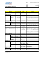
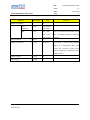
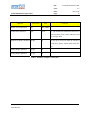
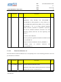
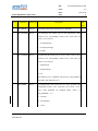
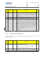
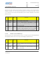
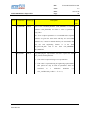
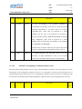
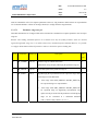
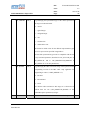
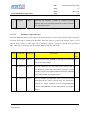
EGOS-MCS-S2K-ICD-0001 Ref.: SCOS-2000 Database Import ICD Support of NIS Throw Events Issue: 6. 9 Date: 2010-07-06 Page: 232 See Section 3.3.3.2.1. Two different types of Throw Events are supported in S2K-R5: Throw Events which are destined to the SLE Service Provider (TMTCS) and Throw Events which will be executed by the SLE Service User (NIS). Extend range of CSP_FPNUM See Section 3.3.3.3.4. The allowed range for the number of formal to 65535 parameters associated to a command sequence has been extended to 65535. Deprecate capability to See Section 3.3.2.4.1. As from R5.0, there is no gain in associating several associate different TM packets different packets to the same SPID. In R5.0 packets are in fact stored in a to the same SPID database and so there is no more the gain of ‘merging’ various packets into a single file. Document clarifications introduced in ICD version 6.5 but applicable to all SCOS releases: Clarification about the use of See Section 3.3.2.3.1. In case the MISCconfig variable limit checking optimised BEHV_ENABLE_OPTIMIZATION is set to 1 (Behaviour Limit Checker processing optimised processing enabled), the value specified for the MISCconfig variable MVC_MAX_CONST_NUMBR must be higher than the maximum value assigned to the field OCF_NBCHK in the ocf table. Correct the description of See Table 5 of Appendix A. Bring the description of variable length string variable length string parameters in line with the correct description as given in Table of Appendix parameters. A. Split the fields whose This editorial change has been applied to the following fields: TPCF_SIZE, description is too long and does CCF_CTYPE, CSS_RELTIME, CSS_EXTIME, SDF_VTYPE not fit into a single page. ESA/OPS-GIC Ref.: SCOS-2000 Database Import ICD EGOS-MCS-S2K-ICD-0001 Issue: 6. 9 Date: 2010-07-06 Page: 233 Clarify the use of the pid.dat Minor modification in the description of the pid-dat table (see Section fields for identifying TM 3.3.2.4.1. packets (implementation of DCR-3398). Document clarifications introduced in ICD version 6.6 but applicable to all SCOS releases: S2K-50-DCR-755 Minor editorial change : description of OCP_TYPE updated S2K-50-DCR-1023 Minor editorial change : description of CCF_HIPRI updated (TCs which are flagged as High-Priority cannot be aggregated (i.e. blocked). S2K-SPR-3400 S2K-SPR-4646. Update the description of limitations for CDF_ELTYPE/SDF_FTYPE combinations. These have been defined along with the fix of S2K-SPR3400/S2K-SPR-4646 ESA/OPS-GIC Ref.: SCOS-2000 Database Import ICD EGOS-MCS-S2K-ICD-0001 Issue: 6. 9 Date: 2010-07-06 Page: 234 Changes applicable as from R5.2 implemented in ICD version 6.7: S2K-DCR-5146 Addition of PCF_DARC field. S2K-SPR-3797 Increased PCF description field to 24 characters. S2K-SCR-4917: Time PCF_CORR and PCF_OBTID added to the PCF table. Correlation – support of CPC_CORR and CPC_OBTID added to the CPC table. encoding of time parameters dependent on OBT ID and Added support for time parameters of type (9,30) meaning Unix time format. support for time parameters in Unix time format. S2K-SPR-5711 PCF_DARC and PCF_ENDIAN added for DARC integration. Document clarifications introduced in ICD version 6.7 but applicable to all SCOS releases: S2K-SPR-4211 Updated the Description of the Table field PCF_VALUE. Added the information: "This field can take 32 bits value at maximum (FFFF FFFF)" (See section 3.3.3.2.3) S2K-SPR-4787 Updated the Description of the Table field PCF_NATUR. In the column “Ma/Def” inserted a “M” for describing this field as mandatory (See section 3.3.2.1.1) S2K-DCR-5502 Editorial fixes: 1. Split the description of the field CDF_VALUE in two parts (it does not fit in one page) (editorial). 2. Change description of GPF_MINUT: the data type is an integer (not a float) and the allowed range is 0...59 3. PIC_APID cannot be considered as key field as it can be left null or even omitted. 4. CCF_EXEC: the text after 'N' is to be updated (editorial) ESA/OPS-GIC Ref.: SCOS-2000 Database Import ICD EGOS-MCS-S2K-ICD-0001 Issue: 6. 9 Date: 2010-07-06 Page: 235 5. CPC_CATEG, in the 'T' option CPC_PARREF should be CPC_PAFREF 6. Clarify unit and size of fields GFP_UPUN and SPF_UPUN (milliseconds?) 7. PIC_PI2_OFF: the offset is from the START of the s2k packet body, not from the end (as correctly said in PIC_PI1_OFF) 8. "history files" are still mentioned in the document (e.g. page 3). Replace "History files" with "packet archive" S2K-DCR-4655 Apendix B, Figure 6 updated. S2K-DCR-3909 Restriction of CVS_ID values to signed short int. S2K-DCR-5192 Support of little endianity (addition of PCF_ENDIAN) S2K-DCR-5505 Clarification of CDF_BIT constraints. S2K-DCR-5303 PUS Support in S2K: Appendix C added. S2K-SPR-4911 The CAF_INTER field has been present in SCOS-2000 since R4, but this feature was never documented. Description of field added to ICD. ESA/OPS-GIC Ref.: SCOS-2000 Database Import ICD EGOS-MCS-S2K-ICD-0001 Issue: 6. 9 Date: 2010-07-06 Page: 236 Document clarifications introduced in ICD version 6.9 but applicable to all SCOS releases: S2K-DCR-3909 Update of length (Number(5) for CVE_CVSID and CVP_CVSID 6.9 according to the length of CVS_ID S2K-DCR-5743 Updates for PCF_OBTID, CPC_OBTID applicable from s2k52. 6.9 S2K-NCR-5531 Update description of field CVS_UNCERTAINTY 6.9 S2K-DCR-6203 New section 3.3.2.1.5 describing the System Control 6.9 Changes applicable as from R5.2 in ICD version 6.7: S2K-SCR-3774 Override command verification window specified in TcSpacon. CVS_UNCERTAINTY added. ESA/OPS-GIC