1
To our customers,
Old Company Name in Catalogs and Other Documents
On April 1st, 2010, NEC Electronics Corporation merged with Renesas Technology
Corporation, and Renesas Electronics Corporation took over all the business of both
companies. Therefore, although the old company name remains in this document, it is a valid
Renesas Electronics document. We appreciate your understanding.
Renesas Electronics website: http://www.renesas.com
April 1st, 2010
Renesas Electronics Corporation
Issued by: Renesas Electronics Corporation (http://www.renesas.com)
Send any inquiries to http://www.renesas.com/inquiry.
Notice
1.
2.
3.
4.
5.
6.
7.
All information included in this document is current as of the date this document is issued. Such information, however, is
subject to change without any prior notice. Before purchasing or using any Renesas Electronics products listed herein, please
confirm the latest product information with a Renesas Electronics sales office. Also, please pay regular and careful attention to
additional and different information to be disclosed by Renesas Electronics such as that disclosed through our website.
Renesas Electronics does not assume any liability for infringement of patents, copyrights, or other intellectual property rights
of third parties by or arising from the use of Renesas Electronics products or technical information described in this document.
No license, express, implied or otherwise, is granted hereby under any patents, copyrights or other intellectual property rights
of Renesas Electronics or others.
You should not alter, modify, copy, or otherwise misappropriate any Renesas Electronics product, whether in whole or in part.
Descriptions of circuits, software and other related information in this document are provided only to illustrate the operation of
semiconductor products and application examples. You are fully responsible for the incorporation of these circuits, software,
and information in the design of your equipment. Renesas Electronics assumes no responsibility for any losses incurred by
you or third parties arising from the use of these circuits, software, or information.
When exporting the products or technology described in this document, you should comply with the applicable export control
laws and regulations and follow the procedures required by such laws and regulations. You should not use Renesas
Electronics products or the technology described in this document for any purpose relating to military applications or use by
the military, including but not limited to the development of weapons of mass destruction. Renesas Electronics products and
technology may not be used for or incorporated into any products or systems whose manufacture, use, or sale is prohibited
under any applicable domestic or foreign laws or regulations.
Renesas Electronics has used reasonable care in preparing the information included in this document, but Renesas Electronics
does not warrant that such information is error free. Renesas Electronics assumes no liability whatsoever for any damages
incurred by you resulting from errors in or omissions from the information included herein.
Renesas Electronics products are classified according to the following three quality grades: “Standard”, “High Quality”, and
“Specific”. The recommended applications for each Renesas Electronics product depends on the product’s quality grade, as
indicated below. You must check the quality grade of each Renesas Electronics product before using it in a particular
application. You may not use any Renesas Electronics product for any application categorized as “Specific” without the prior
written consent of Renesas Electronics. Further, you may not use any Renesas Electronics product for any application for
which it is not intended without the prior written consent of Renesas Electronics. Renesas Electronics shall not be in any way
liable for any damages or losses incurred by you or third parties arising from the use of any Renesas Electronics product for an
application categorized as “Specific” or for which the product is not intended where you have failed to obtain the prior written
consent of Renesas Electronics. The quality grade of each Renesas Electronics product is “Standard” unless otherwise
expressly specified in a Renesas Electronics data sheets or data books, etc.
“Standard”:
8.
9.
10.
11.
12.
Computers; office equipment; communications equipment; test and measurement equipment; audio and visual
equipment; home electronic appliances; machine tools; personal electronic equipment; and industrial robots.
“High Quality”: Transportation equipment (automobiles, trains, ships, etc.); traffic control systems; anti-disaster systems; anticrime systems; safety equipment; and medical equipment not specifically designed for life support.
“Specific”:
Aircraft; aerospace equipment; submersible repeaters; nuclear reactor control systems; medical equipment or
systems for life support (e.g. artificial life support devices or systems), surgical implantations, or healthcare
intervention (e.g. excision, etc.), and any other applications or purposes that pose a direct threat to human life.
You should use the Renesas Electronics products described in this document within the range specified by Renesas Electronics,
especially with respect to the maximum rating, operating supply voltage range, movement power voltage range, heat radiation
characteristics, installation and other product characteristics. Renesas Electronics shall have no liability for malfunctions or
damages arising out of the use of Renesas Electronics products beyond such specified ranges.
Although Renesas Electronics endeavors to improve the quality and reliability of its products, semiconductor products have
specific characteristics such as the occurrence of failure at a certain rate and malfunctions under certain use conditions. Further,
Renesas Electronics products are not subject to radiation resistance design. Please be sure to implement safety measures to
guard them against the possibility of physical injury, and injury or damage caused by fire in the event of the failure of a
Renesas Electronics product, such as safety design for hardware and software including but not limited to redundancy, fire
control and malfunction prevention, appropriate treatment for aging degradation or any other appropriate measures. Because
the evaluation of microcomputer software alone is very difficult, please evaluate the safety of the final products or system
manufactured by you.
Please contact a Renesas Electronics sales office for details as to environmental matters such as the environmental
compatibility of each Renesas Electronics product. Please use Renesas Electronics products in compliance with all applicable
laws and regulations that regulate the inclusion or use of controlled substances, including without limitation, the EU RoHS
Directive. Renesas Electronics assumes no liability for damages or losses occurring as a result of your noncompliance with
applicable laws and regulations.
This document may not be reproduced or duplicated, in any form, in whole or in part, without prior written consent of Renesas
Electronics.
Please contact a Renesas Electronics sales office if you have any questions regarding the information contained in this
document or Renesas Electronics products, or if you have any other inquiries.
(Note 1) “Renesas Electronics” as used in this document means Renesas Electronics Corporation and also includes its majorityowned subsidiaries.
(Note 2) “Renesas Electronics product(s)” means any product developed or manufactured by or for Renesas Electronics.
Preliminary User’s Manual
QB-703425
(IECUBE for V850E/Dx3)
Target Devices:
µPD703420
µPD70(F)3421
µPD703422
µPD70F3423
µPD70F3424
µPD70F3425
Document No. U17678EE1V0UM00
Date Published December 2005
NEC Electronics Corporation 2005
Printed in Germany
NOTES FOR CMOS DEVICES
1
VOLTAGE APPLICATION WAVEFORM AT INPUT PIN
Waveform distortion due to input noise or a reflected wave may cause malfunction. If the input of the
CMOS device stays in the area between VIL (MAX) and VIH (MIN) due to noise, etc., the device may
malfunction. Take care to prevent chattering noise from entering the device when the input level is fixed,
and also in the transition period when the input level passes through the area between VIL (MAX) and
VIH (MIN).
2
HANDLING OF UNUSED INPUT PINS
Unconnected CMOS device inputs can be cause of malfunction. If an input pin is unconnected, it is
possible that an internal input level may be generated due to noise, etc., causing malfunction. CMOS
devices behave differently than Bipolar or NMOS devices. Input levels of CMOS devices must be fixed
high or low by using pull-up or pull-down circuitry. Each unused pin should be connected to VDD or GND
via a resistor if there is a possibility that it will be an output pin. All handling related to unused pins must
be judged separately for each device and according to related specifications governing the device.
3
PRECAUTION AGAINST ESD
A strong electric field, when exposed to a MOS device, can cause destruction of the gate oxide and
ultimately degrade the device operation. Steps must be taken to stop generation of static electricity as
much as possible, and quickly dissipate it when it has occurred. Environmental control must be
adequate. When it is dry, a humidifier should be used. It is recommended to avoid using insulators that
easily build up static electricity. Semiconductor devices must be stored and transported in an anti-static
container, static shielding bag or conductive material. All test and measurement tools including work
benches and floors should be grounded. The operator should be grounded using a wrist strap.
Semiconductor devices must not be touched with bare hands. Similar precautions need to be taken for
PW boards with mounted semiconductor devices.
4
STATUS BEFORE INITIALIZATION
Power-on does not necessarily define the initial status of a MOS device. Immediately after the power
source is turned ON, devices with reset functions have not yet been initialized. Hence, power-on does
not guarantee output pin levels, I/O settings or contents of registers. A device is not initialized until the
reset signal is received. A reset operation must be executed immediately after power-on for devices
with reset functions.
5
INPUT OF SIGNAL DURING POWER OFF STATE
Do not input signals or an I/O pull-up power supply while the device is not powered. The current
injection that results from input of such a signal or I/O pull-up power supply may cause malfunction and
the abnormal current that passes in the device at this time may cause degradation of internal elements.
Input of signals during the power off state must be judged separately for each device and according to
related specifications governing the device.
All other product, brand, or trade names used in this publication are the trademarks
or registered trademarks of their respective trademark owners.
Product specifications are subject to change without notice. To ensure that you have the latest
product data, please contact your local NEC Electronics sales office.
2
Preliminary User’s Manual U17678EE1V0UM00
• The information contained in this document is being issued in advance of the production cycle for the
product. The parameters for the product may change before final production or NEC Electronics
Corporation, at its own discretion, may withdraw the product prior to its production.
• Not all products and/or types are available in every country. Please check with an NEC Electronics sales
representative for availability and additional information.
• No part of this document may be copied or reproduced in any form or by any means without the prior written consent
of NEC Electronics. NEC Electronics assumes no responsibility for any errors that may appear in this document.
• NEC Electronics does not assume any liability for infringement of patents, copyrights or other intellectual property
rights of third parties by or arising from the use of NEC Electronics products listed in this document or any other
liability arising from the use of such products. No license, express, implied or otherwise, is granted under any
patents, copyrights or other intellectual property rights of NEC Electronics or others.
• Descriptions of circuits, software and other related information in this document are provided for illustrative purposes
in semiconductor product operation and application examples. The incorporation of these circuits, software and
information in the design of a customer's equipment shall be done under the full responsibility of the customer. NEC
Electronics assumes no responsibility for any losses incurred by customers or third parties arising from the use of
these circuits, software and information.
• While NEC Electronics endeavors to enhance the quality, reliability and safety of NEC Electronics products,
customers agree and acknowledge that the possibility of defects thereof cannot be eliminated entirely. To minimize
risks of damage to property or injury (including death) to persons arising from defects in NEC Electronics products,
customers must incorporate sufficient safety measures in their design, such as redundancy, fire-containment and
anti-failure features.
• NEC Electronics products are classified into the following three quality grades: "Standard", "Special" and "Specific".
The "Specific" quality grade applies only to NEC Electronics products developed based on a customer-designated
"quality assurance program" for a specific application. The recommended applications of an NEC Electronics
products depend on its quality grade, as indicated below. Customers must check the quality grade of each NEC
Electronics product before using it in a particular application.
"Standard": Computers, office equipment, communications equipment, test and measurement equipment, audio and
visual equipment, home electronic appliances, machine tools, personal electronic equipment and
industrial robots.
"Special": Transportation equipment (automobiles, trains, ships, etc.), traffic control systems, anti-disaster
systems, anti-crime systems, safety equipment and medical equipment (not specifically designed for life
support).
"Specific": Aircraft, aerospace equipment, submersible repeaters, nuclear reactor control systems, life support
systems and medical equipment for life support, etc.
The quality grade of NEC Electronics products is "Standard" unless otherwise expressly specified in NEC
Electronics data sheets or data books, etc. If customers wish to use NEC Electronics products in applications
not intended by NEC Electronics, they must contact an NEC Electronics sales representative in advance to
determine NEC Electronics' willingness to support a given application.
(Note)
(1) "NEC Electronics" as used in this statement means NEC Electronics Corporation and also includes its
majority-owned subsidiaries.
(2) "NEC Electronics products" means any product developed or manufactured by or for NEC Electronics (as
defined above).
M5D 02. 11-1
Preliminary User’s Manual U17678EE1V0UM00
3
For further information,
please contact:
NEC Electronics Corporation
1753, Shimonumabe, Nakahara-ku,
Kawasaki, Kanagawa 211-8668,
Japan
Tel: 044-435-5111
http://www.necel.com/
[America]
[Europe]
[Asia & Oceania]
NEC Electronics America, Inc.
2880 Scott Blvd.
Santa Clara, CA 95050-2554, U.S.A.
Tel: 408-588-6000
800-366-9782
http://www.am.necel.com/
NEC Electronics (Europe) GmbH
Arcadiastrasse 10
40472 Düsseldorf, Germany
Tel: 0211-65030
http://www.eu.necel.com/
NEC Electronics (China) Co., Ltd
7th Floor, Quantum Plaza, No. 27 ZhiChunLu Haidian
District, Beijing 100083, P.R.China
TEL: 010-8235-1155
http://www.cn.necel.com/
Hanover Office
Podbielski Strasse 166 B
30177 Hannover
Tel: 0 511 33 40 2-0
NEC Electronics Shanghai Ltd.
Room 2509-2510, Bank of China Tower,
200 Yincheng Road Central,
Pudong New Area, Shanghai P.R. China P.C:200120
Tel: 021-5888-5400
http://www.cn.necel.com/
Munich Office
Werner-Eckert-Strasse 9
81829 München
Tel: 0 89 92 10 03-0
Stuttgart Office
Industriestrasse 3
70565 Stuttgart
Tel: 0 711 99 01 0-0
United Kingdom Branch
Cygnus House, Sunrise Parkway
Linford Wood, Milton Keynes
MK14 6NP, U.K.
Tel: 01908-691-133
Succursale Française
9, rue Paul Dautier, B.P. 52180
78142 Velizy-Villacoublay Cédex
France
Tel: 01-3067-5800
Sucursal en España
Juan Esplandiu, 15
28007 Madrid, Spain
Tel: 091-504-2787
NEC Electronics Hong Kong Ltd.
12/F., Cityplaza 4,
12 Taikoo Wan Road, Hong Kong
Tel: 2886-9318
http://www.hk.necel.com/
Seoul Branch
11F., Samik Lavied’or Bldg., 720-2,
Yeoksam-Dong, Kangnam-Ku,
Seoul, 135-080, Korea
Tel: 02-558-3737
NEC Electronics Taiwan Ltd.
7F, No. 363 Fu Shing North Road
Taipei, Taiwan, R. O. C.
Tel: 02-2719-2377
NEC Electronics Singapore Pte. Ltd.
238A Thomson Road,
#12-08 Novena Square,
Singapore 307684
Tel: 6253-8311
http://www.sg.necel.com/
Tyskland Filial
Täby Centrum
Entrance S (7th floor)
18322 Täby, Sweden
Tel: 08 638 72 00
Filiale Italiana
Via Fabio Filzi, 25/A
20124 Milano, Italy
Tel: 02-667541
Branch The Netherlands
Limburglaan 5
5616 HR Eindhoven
The Netherlands
Tel: 040 265 40 10
G05.11-1A
4
Preliminary User’s Manual U17678EE1V0UM00
Introduction
Target Readers
This manual is intended for users who design and develop application systems
using the V850E/Dx3.
Purpose
The purpose of this manual is to describe the proper operation of the
QB-703425, and its basic specifications.
Organization
This manual is broadly divided into the following parts.
Overview
Setup procedure
Cautions
How to read this manual
It is assumed that the reader of this manual has general knowledge in the fields
of electrical engineering, logic circuits, and microcontrollers. This manual
explains the basic setup procedure, so read this document before using the
QB-703425.
To learn about the basic specifications and operation methods.
→ Read this manual in the order of the CONTENTS.
To learn about software settings such as operation methods and command functions.
→ Read the user’s manual of the debugger that is used.
Legend
Symbols and notation are used as follows:
Weight in data notation
: Left is high-order column, right is low order column
Active low notation
: xxx (pin or signal name is over-scored) or
/xxx (slash before signal name)
Memory map address:
: High order at high stage and low order at low stage
Note
: Explanation of (Note) in the text
Caution
: Item deserving extra attention
Remark
: Supplementary explanation to the text
Numeric notation
: Binary... XXXX or XXXB
Decimal... XXXX
Hexadecimal... XXXXH or 0x XXXX
Prefixes representing powers of 2 (address space, memory capacity)
K (kilo): 210 = 1024
M (mega): 220 = 10242 = 1,048,576
G (giga): 230 = 10243 = 1,073,741,824
Preliminary User’s Manual U17678EE1V0UM00
5
Introduction
Terminology
The meanings of terms used in this manual are listed below.
Term
Meaning
Target device
Refers to the device targeted for emulation.
Target system
Refers to the system targeted for debugging.
This includes the target program and the hardware created by the user. In the narrow
sense, it means hardware only.
Related Documents When using this manual, refer to the following manuals.
The related documents indicated in this publication may include preliminary versions.
However, preliminary versions are not marked as such.
• Documents related to development tools (user’s manuals)
Document Name
Document Number
QB-703425 In-Circuit Emulator
This manual
QB-703425 In-Circuit-Emulator Option Board
Operating Precautions Target
Customer Notification
EEDT-OP-0027
- current version
CPDW9X/NT-CDR-V85X
GHS integrated development
environment (PC, MS Windows based)
Ver.4.07 or
- current version
V850 Series CPDW9X/NT-CDR-V85X Operating
Precautions MULTI 2000 Integrated Development
Environment
Customer Notification
DTOP0010V30
- current version
850eserv / Detailed information listing
Read Me File for 850ESERV
850eserv.txt
- current version
IEQBUTL / IECUBE Utility
Read Me File for IECUBE Util- IEQBUTL_E2.03c.txt
ity IEQBUTL
or - current version
Note: Download the documents from the NEC Electronics (Europe) GmbH web site.
URL: http://www.eu.necel.com/products/micro/
6
Preliminary User’s Manual U17678EE1V0UM00
Introduction
General Cautions on handling this product
1. NEC Electronics’ warranty does not cover the following cases:
• When the QB-703425 is disassembled, reconstructed, or modified by the user
• When the QB-703425 receives a heavy shock such as being dropped or falling down
• When the QB-703425 is used with excessive voltage or is stored outside the guaranteed
temperature range or guaranteed humidity range
• When power is applied while the AC adapter, USB interface cable, or target system is not
connected securely
• When the AC adapter cable, USB interface cable, or extension probe is excessively twisted or
stretched
• When an AC adapter other than the one supplied with the QB-703425 is used
• When water is spilled on the QB-703425
2. Cautions on safe use
• The QB-703425 heats up (to approx. 50 to 60°C) when it operates for a long time. Take care not
to receive injuries such as burns from a rise in the temperature.
• Be very careful to avoid electric shocks. There is risk of electric shock if the product is used as
described in item 1 above.
Preliminary User’s Manual U17678EE1V0UM00
7
[MEMO]
8
Preliminary User’s Manual U17678EE1V0UM00
Table of Contents
Introduction. . . . . . . . . . . . . . . . . . . . . . . . . . . . . . . . . . . . . . . . . . . . . . . . . . . . 5
Chapter 1
1.1
1.2
1.3
1.4
Chapter 2
2.1
2.2
2.3
2.4
2.5
2.6
2.7
2.8
2.9
Overview . . . . . . . . . . . . . . . . . . . . . . . . . . . . . . . . . . . . . . . . . . . . . . . . . . . . . 15
Hardware Specifications . . . . . . . . . . . . . . . . . . . . . . . . . . . . . . . . . . . . . . . . . . . . . . . . 16
System Specifications . . . . . . . . . . . . . . . . . . . . . . . . . . . . . . . . . . . . . . . . . . . . . . . . . . 18
System Configuration . . . . . . . . . . . . . . . . . . . . . . . . . . . . . . . . . . . . . . . . . . . . . . . . . . 19
Packing Contents. . . . . . . . . . . . . . . . . . . . . . . . . . . . . . . . . . . . . . . . . . . . . . . . . . . . . . 22
IECUBE Setup Procedure . . . . . . . . . . . . . . . . . . . . . . . . . . . . . . . . . . . . . . . 23
Names and Functions of Hardware . . . . . . . . . . . . . . . . . . . . . . . . . . . . . . . . . . . . . . . 24
Removing Acrylic Board . . . . . . . . . . . . . . . . . . . . . . . . . . . . . . . . . . . . . . . . . . . . . . . . 25
Clock Settings . . . . . . . . . . . . . . . . . . . . . . . . . . . . . . . . . . . . . . . . . . . . . . . . . . . . . . . . 26
2.3.1
Overview of clock settings . . . . . . . . . . . . . . . . . . . . . . . . . . . . . . . . . . . . . . . . . 26
2.3.2
How to set clock . . . . . . . . . . . . . . . . . . . . . . . . . . . . . . . . . . . . . . . . . . . . . . . . . 26
2.3.3
How to change crystal . . . . . . . . . . . . . . . . . . . . . . . . . . . . . . . . . . . . . . . . . . . . 27
Target IECUBE Settings . . . . . . . . . . . . . . . . . . . . . . . . . . . . . . . . . . . . . . . . . . . . . . . . 28
Software Setup . . . . . . . . . . . . . . . . . . . . . . . . . . . . . . . . . . . . . . . . . . . . . . . . . . . . . . . . 28
2.5.1
When ID850 debugger is used . . . . . . . . . . . . . . . . . . . . . . . . . . . . . . . . . . . . . . 28
2.5.2
When a debugger other than ID850QB (such as Multi) is used . . . . . . . . . . . . . 28
2.5.3
Download speed . . . . . . . . . . . . . . . . . . . . . . . . . . . . . . . . . . . . . . . . . . . . . . . . . 29
Mounting and Connecting Connectors . . . . . . . . . . . . . . . . . . . . . . . . . . . . . . . . . . . . 30
2.6.1
Use . . . . . . . . . . . . . . . . . . . . . . . . . . . . . . . . . . . . . . . . . . . . . . . . . . . . . . . . . . . 30
2.6.2
Cautions on Handling Connectors . . . . . . . . . . . . . . . . . . . . . . . . . . . . . . . . . . . 32
Connecting IECUBE to Target System. . . . . . . . . . . . . . . . . . . . . . . . . . . . . . . . . . . . . 33
2.7.1
Connection without using extension probe (QB-208-EP-01S) . . . . . . . . . . . . . . 33
2.7.2
Connection using extension probe (QB-208-EP-01S) . . . . . . . . . . . . . . . . . . . . 34
Connecting USB Interface Cable and AC Adapter . . . . . . . . . . . . . . . . . . . . . . . . . . . 38
Power Application/Shutdown . . . . . . . . . . . . . . . . . . . . . . . . . . . . . . . . . . . . . . . . . . . . 38
Chapter 3
List of Factory Settings . . . . . . . . . . . . . . . . . . . . . . . . . . . . . . . . . . . . . . . . . 39
Chapter 4
Differences Between Target Device and IECUBE . . . . . . . . . . . . . . . . . . . . 41
4.1
Functions Emulated Differently . . . . . . . . . . . . . . . . . . . . . . . . . . . . . . . . . . . . . . . . . . 41
4.1.1
Differences by emulating POC . . . . . . . . . . . . . . . . . . . . . . . . . . . . . . . . . . . . . . 41
4.1.2
Differences on Interface Pins (Electrical Characteristics). . . . . . . . . . . . . . . . . . 42
4.1.3
Differences by emulating RESET . . . . . . . . . . . . . . . . . . . . . . . . . . . . . . . . . . . . 43
4.1.4
Differences by emulating MODE switch . . . . . . . . . . . . . . . . . . . . . . . . . . . . . . . 43
4.1.5
iRAM . . . . . . . . . . . . . . . . . . . . . . . . . . . . . . . . . . . . . . . . . . . . . . . . . . . . . . . . . . 43
4.1.6
FOUT- and WDT-clock supply differ from device in standby mode . . . . . . . . . . 43
4.1.7
PSM.OSCDIS reset value different to device . . . . . . . . . . . . . . . . . . . . . . . . . . . 44
4.1.8
Timing different to device for oscillation stabilization time . . . . . . . . . . . . . . . . . 44
4.1.9
Break precaution related to ADC macro . . . . . . . . . . . . . . . . . . . . . . . . . . . . . . . 44
4.2
Notes on Emulation . . . . . . . . . . . . . . . . . . . . . . . . . . . . . . . . . . . . . . . . . . . . . . . . . . . . 46
4.2.1
Access to CPU register DBPSW, DBPC, ECR. . . . . . . . . . . . . . . . . . . . . . . . . . 46
4.2.2
PSC register access . . . . . . . . . . . . . . . . . . . . . . . . . . . . . . . . . . . . . . . . . . . . . . 46
4.2.3
Trace display order of data access trace . . . . . . . . . . . . . . . . . . . . . . . . . . . . . . 46
4.2.4
Simultaneous execution of two instructions when hardware break is set. . . . . . 47
4.2.5
Non map break . . . . . . . . . . . . . . . . . . . . . . . . . . . . . . . . . . . . . . . . . . . . . . . . . . 47
4.2.6
Guarded area access break delay . . . . . . . . . . . . . . . . . . . . . . . . . . . . . . . . . . . 47
4.2.7
Break during program execution in internal RAM . . . . . . . . . . . . . . . . . . . . . . . . 48
4.2.8
Program execution in internal RAM and simultaneous DMA transfer access
to/from internal RAM. . . . . . . . . . . . . . . . . . . . . . . . . . . . . . . . . . . . . . . . . . . . . . 48
4.3
Functions Not Supported . . . . . . . . . . . . . . . . . . . . . . . . . . . . . . . . . . . . . . . . . . . . . . . 49
Preliminary User’s Manual U17678EE1V0UM00
9
Chapter 5
Notes on Target System Design . . . . . . . . . . . . . . . . . . . . . . . . . . . . . . . . . . 51
5.1
When Extension Probe Is Not Used . . . . . . . . . . . . . . . . . . . . . . . . . . . . . . . . . . . . . . . 51
5.1.1
V850E/Dx3 - 144-pin . . . . . . . . . . . . . . . . . . . . . . . . . . . . . . . . . . . . . . . . . . . . . 51
5.2
When Extension Probe Is Used . . . . . . . . . . . . . . . . . . . . . . . . . . . . . . . . . . . . . . . . . . 52
5.2.1
V850E/Dx3 - 144-pin with probe . . . . . . . . . . . . . . . . . . . . . . . . . . . . . . . . . . . . . 52
Chapter 6
6.1
6.2
6.3
6.4
6.5
6.6
6.7
10
Connector Probe Package Drawings . . . . . . . . . . . . . . . . . . . . . . . . . . . . . . 53
Target Connector . . . . . . . . . . . . . . . . . . . . . . . . . . . . . . . . . . . . . . . . . . . . . . . . . . . . . . 53
Foot Patterns of Target Connectors. . . . . . . . . . . . . . . . . . . . . . . . . . . . . . . . . . . . . . . 54
Exchange Adapter . . . . . . . . . . . . . . . . . . . . . . . . . . . . . . . . . . . . . . . . . . . . . . . . . . . . . 55
Mounting Adapter . . . . . . . . . . . . . . . . . . . . . . . . . . . . . . . . . . . . . . . . . . . . . . . . . . . . . 56
YQ Adapter . . . . . . . . . . . . . . . . . . . . . . . . . . . . . . . . . . . . . . . . . . . . . . . . . . . . . . . . . . . 58
Spacer Adapter. . . . . . . . . . . . . . . . . . . . . . . . . . . . . . . . . . . . . . . . . . . . . . . . . . . . . . . . 59
Extension Probe. . . . . . . . . . . . . . . . . . . . . . . . . . . . . . . . . . . . . . . . . . . . . . . . . . . . . . . 60
Preliminary User’s Manual U17678EE1V0UM00
List of Figures
Figure 1-1:
Figure 1-2:
Figure 1-3:
Figure 1-4:
Figure 2-1:
Figure 2-2:
Figure 2-3:
Figure 2-4:
Figure 2-5:
Figure 2-6:
Figure 2-7:
Figure 2-8:
Figure 2-9:
Figure 2-10:
Figure 2-11:
Figure 2-12:
Figure 5-1:
Figure 5-2:
Figure 6-1:
Figure 6-2:
Figure 6-3:
Figure 6-4:
Figure 6-5:
Figure 6-6:
Figure 6-7:
Figure 6-8:
IECUBE ....................................................................................................................... 15
IECUBE Dimensions ................................................................................................... 17
Typical System Configuration...................................................................................... 19
Target Probe ............................................................................................................... 20
Names and Functions in QB-703425 .......................................................................... 24
Removing Acrylic Board .............................................................................................. 25
Clock Adapter Board - Parts Assembling .................................................................... 27
Mounting of NQPACK144SD ...................................................................................... 30
Mounting Device.......................................................................................................... 31
NQPACK144SD and Device Pin ................................................................................. 31
Connection without using Extension Probe ................................................................. 33
How to use Probe Holder ............................................................................................ 34
Connection of GND Lines............................................................................................ 35
Location at which GND Line can be connected .......................................................... 36
Connection when using Extension Probe.................................................................... 37
Connector Position ...................................................................................................... 38
V850E/Dx3 - 144-pin ................................................................................................... 51
V850E/Dx3 -144-pin with probe .................................................................................. 52
Target Connector for 144-pin ...................................................................................... 53
Foot Pattern of Target Connector for 144-pin ............................................................. 54
Exchange Adapter for 144-pin..................................................................................... 55
Mounting Adapter for 144-pin ...................................................................................... 56
Mounting Adapter for 208-pin ...................................................................................... 57
YQ Adapter for 144-pin ............................................................................................... 58
Spacer Adapter for 144-pin ......................................................................................... 59
Extension Probe .......................................................................................................... 60
Preliminary User’s Manual U17678EE1V0UM00
11
12
Preliminary User’s Manual U17678EE1V0UM00
List of Tables
Table 1-1:
Table 1-2:
Table 1-3:
Table 2-1:
Table 3-1:
Table 4-1:
QB-703425 Hardware Specifications ............................................................................. 16
QB-703425 System Specifications ................................................................................. 18
List of Probes and Connectors for Each Target Device ................................................. 21
List of Hardware Settings When Clock Is Set................................................................. 26
List of Factory Settings ................................................................................................... 39
Clock Connector CN8..................................................................................................... 42
Preliminary User’s Manual U17678EE1V0UM00
13
14
Preliminary User’s Manual U17678EE1V0UM00
Chapter 1 Overview
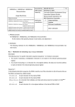
The QB-703425 (IECUBE) is an in-circuit emulator used to emulate the V850E/Dx3 devices. By using
IECUBE, hardware and software can be debugged efficiently in system development.
In this manual, the basic setup procedure, hardware specifications, system specifications, and switch
settings are described.
This document describes the QB-703425 as IECUBE.
Figure 1-1:
IECUBE
Preliminary User’s Manual U17678EE1V0UM00
15
Chapter 1
Overview
1.1 Hardware Specifications
Table 1-1:
QB-703425 Hardware Specifications
Item
Specification
Target device
V850E/Dx3
Target system interface voltage
(unit: V)
DVDD5 = 3.0 V ~ 5.5 V,
BVDD5 = 3.0 V ~ 5.5 V,
AVDD = 3.2 V ~ 5.5 V, SMVDD5 = 3.2 V ~ 5.5 V,
VDD5 = 3.2 V ~ 5.5 V,
VSS5 = BVSS5 = DVSS5 = SMVSS5 = AVSS = 0 V
Maximum operating frequency
48 MHz + SSCG modulation range
Operating temperature range
0 to 40°C (without condensation)
Storage temperature range
-15 to 60°C (without condensation)
Package dimensions
See below
Power
consumption
AC adapter for IECUBE
15 V, 1 A
Target system power supply
Lower than that of target device
Weight
475 g - 537 g
Host interface
USB interface (1.1 and 2.0)
16
Preliminary User’s Manual U17678EE1V0UM00
Chapter 1
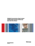
Figure 1-2:
Overview
IECUBE Dimensions
112.7 mm Notes 1, 6
128.0 mm
84.6 mm Note 2
68.0 mm Notes 3, 5
78.5 mm
89.0 mm
Rear spacer
Note 4
Front spacer
Notes: 1. Not including projection of power supply switch.
2. Including projection of screw for fixing rear spacer
3. Shortest dimension for the rear spacer (+30 mm max.)
4. The front spacer dimension is variable between 20 mm (max.) and 5 mm (min.)
5. The height dimension (68.0 mm / 78.5 mm / 89.0 mm) depends on the count of option
boards
6. The fan at the back increase the length to 128.0 mm.
Preliminary User’s Manual U17678EE1V0UM00
17
Chapter 1
Overview
1.2 System Specifications
Table 1-2:
QB-703425 System Specifications
Function
Emulation
Memory capacity
Program execution
function
Break function
Trace function
Internal ROM
1 Mbyte (Maximum)
Internal RAM
60 Kbyte (Maximum)
External memory
None
Real-time execution function
Go, Start From Here, Go & Go, Come Here, Restart,
Return Out
Non-real-time execution function
Step In, Next Over, Slow Motion
Hardware break
Execution: 10 points
Access: 6 points
Software break
2000 points (debugger related)
Fail-safe break
Non-map, I/O illegal, write protect
Other
Trace full break, Manual Break, Timer Over Flow Break
Trace data type
Branch source PC, branch destination PC, all PCs, all
execution data, access data, access address, R/W
status, time stamp, DMA point (start/end)
Trace mode
Speed Priority, Trace Priority
Trace event
Delay trigger, section, qualify
Memory capacity
256k frames
Real-time RAM monitor function
Time measurement function
Specification
256 bytes × 8 points
Measurement clock
Measurement-dedicated clock or CPU clock
Measurement target
Program execution start to end
Start event to end event
Maximum measurement time
About 195 hours (when measurement-dedicated clock is
used)
Minimum resolution
20 ns
Number of timers used for meas8
urement
Measurement result
Execution time (execution start to end)
Max., min., Average, pass count (between events)
Other
Timer overflow break function (1 point)
Coverage function
Optional (under development)
Other functions
Mapping function, event function, register manipulation
function, memory manipulation function
Caution:
18
Some of the functions may not be supported, depending on the debugger used.
Preliminary User’s Manual U17678EE1V0UM00
Chapter 1
Overview
1.3 System Configuration
The system configuration when connecting the QB-703425 to a PC (PC98 series or PC/AT compatible)
is shown below. USB interface that enables communication based on USB (Ver1.1 or Ver2.0).
Connection is possible without optional products.
Connectors vary depending on the target device to be emulated.
Order code for the package is QB-703425-MZZ-EE.
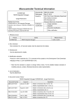
Figure 1-3:
Typical System Configuration
IECUBE
In-circuit emulator
USB cable
ICE <-> PC
AC adapter cable
Flash programmer
Extension probe
QB-208-EP-01S
Exchange adapter
QB-*-EA-*T
Space adapter
QB-*-YS-*T
ICE connector
QB-*-YQ-*T
Mount adapter
QB-*-HQ-*T
Target connector
QB-*-NQ-*T
Target system
One piece of a special space adapter is included on the QB-208-EA-01T. This is required for using this
exchange adapter without extension probe.
Preliminary User’s Manual U17678EE1V0UM00
19
Chapter 1
Figure 1-4:
Overview
Target Probe
Mandatory
Option
Extension probe
NEC:QB-208-EP-01S
Exchange adapter
NEC:QB-144GJ-EA-04T
ICE connector
NEC:QB-144GJ-YQ-01T
Mount adapter
NEC: QB-144GJ-HQ-01T
Target connector
NEC: QB-144GJ-NQ-01T
144 pins
QFP
GJ-UEN
20
Preliminary User’s Manual U17678EE1V0UM00
Chapter 1
Table 1-3:
No.
Name
Overview
List of Probes and Connectors for Each Target Device
Target Device to Be Emulated
V850E/DJ3
µPD70(F)342x-GJ-UEN:
144 QFP (20 mm × 20 mm / 0.5 mm)
<6>
Extension probe
(coaxial type)
QB-208-EP-01S (sold separately)
<7> Spacer adapter
QB-144GJ-YS-01T
(sold separately)Note
<8> Exchange adapter
QB-144GJ-EA-04T
(sold separately)Note
<9> YQ adapter
QB-144GJ-YQ-01T
(sold separately)
<10> Mounting adapter
QB-144GJ-HQ-01T
(sold separately)
<11> Target connector
QB-144GJ-NQ-01T
(sold separately)Note
Note: The accessories included with this product are as shown below.
•
When QB-703425-MZZ-EE is ordered:
The exchange adapter and target connector are not included.
The QB-144GJ-YQ-01T includes different than standard YQGUIDE’s, named YQGUIDE-S3.
“YQGUIDE-S3” is attached between YQ and EA. This must be observed by customer.
Preliminary User’s Manual U17678EE1V0UM00
21
Chapter 1
Overview
1.4 Packing Contents
The packing box of the QB-703425-MZZ-EE contains the following. Make sure that these items are
included.
•
Items included with QB-703425-MZZ-EE
(1) QB-703425 In Circuit Emulator
(2) AC adapter
(3) USB interface cable
(4) PG-FPL flash programmer
(5) Readme First
(6) Registration Card
(7) CE “Note”
(8) QB-703425-MZZ-EE package contents list
22
Preliminary User’s Manual U17678EE1V0UM00
Chapter 2
IECUBE Setup Procedure
This chapter describes the procedure for setting up the QB-703425.
Perform setup using the following procedure.
See 2.1 ”Names and Functions of Hardware” on page 24 for the positions of switches and clocks.
(1)
Clock settings
A 4.000 MHz crystal is mounted at shipment for main clock.
A 32.768 kHz crystal is mounted at shipment for sub clock.
The Ring clock is generated internally only.
There is no need to change the setting. When different type of crystal (e.g. same as on the target
system) shall be used, follow instructions given in this manual.
See 2.2 ”Removing Acrylic Board” on page 25 and 2.3 ”Clock Settings” on page 26 when
changing the crystal.
(2)
Target device setting
It is assumed that the IECUBE target device is the V850E/Dx3 at shipment.
There is no need to change the setting when emulating the V850E/Dx3.When different emulation
option shall be used, follow instructions given in this manual.
See 2.2 ”Removing Acrylic Board” on page 25 and 2.4 ”Target IECUBE Settings” on
page 28 when changing emulation options.
(3)
Software setup
See 2.5 ”Software Setup” on page 28.
(4)
Mounting and connecting connectors
See 2.6 ”Mounting and Connecting Connectors” on page 30.
(5)
Connecting IECUBE to target system
See 2.7 ”Connecting IECUBE to Target System” on page 33.
• When extension probe (QB-208-EP-01S) is used: See 2.7.1.
• When extension probe (QB-208-EP-01S) is not used: See 2.7.2.
(6)
Connecting USB interface cable and AC adapter
See 2.8 ”Connecting USB Interface Cable and AC Adapter” on page 38.
(7)
Power application/shutdown
See 2.9 ”Power Application/Shutdown” on page 38.
Preliminary User’s Manual U17678EE1V0UM00
23
Chapter 2
IECUBE Setup Procedure
2.1 Names and Functions of Hardware
Figure 2-1:
Names and Functions in QB-703425
Top View
Power switch
CN8
Bottom View
SW2
CN3 CN2 CN1
(1)
CN1, CN2, CN3
These are connectors used to connect the exchange adapter or extension probe.
(2)
Clock adapter board connector (for clock) CN8
This is a clock adapter board used for mounting the crystal.
A 4.000 MHz crystal and capacitors, that configure an oscillator circuit are mounted at shipment.
(See 2.3 ”Clock Settings” on page 26 for details.)
(3)
SW2
This is a switch whose setting should be set in case of special emulation.
It is set to default at shipment.
(See 2.4 ”Target IECUBE Settings” on page 28 for details.)
24
Preliminary User’s Manual U17678EE1V0UM00
Chapter 2
(4)
IECUBE Setup Procedure
POWER (red LED)
This is an LED that indicates whether or not the power to IECUBE is on.
LED Status
(5)
IECUBE Status
Lit
The power supply is on.
Extinguished
The power supply is off, or the AC adapter is not connected to IECUBE.
Blinking
An error has occurred internally. (Contact an NEC Electronics sales representative or
distributor.)
TARGET (green LED)
This is an LED that indicates whether or not the power to the target system is on.
LED Status
(6)
Target System Status
Lit
The power supply to the target system is on.
Extinguished
The power supply to the target system is off, or the target system is not connected.
Power supply switch
This is a power switch for IECUBE. This switch is turned off at shipment.
2.2 Removing Acrylic Board
Remove the acrylic board on the bottom surface of IECUBE before changing the settings of jumpers or
clocks.
The acrylic board can be removed by pulling it up.
Figure 2-2:
Removing Acrylic Board
Preliminary User’s Manual U17678EE1V0UM00
25
Chapter 2
IECUBE Setup Procedure
2.3 Clock Settings
2.3.1 Overview of clock settings
Note: Default setting at shipment: clock adapter board is plugged in.There is no need to change the
clock settings for standard use. Only in case of special setting required by customer this is
described herewith.
Two methods are available for setting the clock.
See 2.3.2 ”How to set clock” on page 26 for details.
(1)
(2)
(3)
Use the 4.000 MHz/32.768 kHz crystals mounted on the clock board on IECUBE as the
internal clock.
Mount different 4.000 MHz/32.768 kHz types of crystals onto the clock board on IECUBE.
This is only an option if same type of crystal as on the target system will be used.
The clock input from target system without using clock board one IECUBENote
Note: The IECUBE does not support clock input from the target system. The function by using target
system clock is not guaranteed.
2.3.2 How to set clock
A list of hardware settings for when the clock is set is shown in Table 2-1.
Table 2-1:
List of Hardware Settings When Clock Is Set
Clock to Be Used
Parts Board
Use the 4.00 MHz / 32.768 kHz crystal mounted on the
clock board as the internal clock.
Use the factory setting
Mount different crystals on the clock board and use it
as the internal clock.
The frequency of the crystal that can be used is the
same as that of the target device 4MHz.
Mount the crystal on the
parts board.
Settings other than above are prohibited.
26
Preliminary User’s Manual U17678EE1V0UM00
Chapter 2
IECUBE Setup Procedure
2.3.3 How to change crystal
<1> Remove the clock adapter board. Be careful not to damage IECUBE. Resolder the parts of X1
and X2 by another type. Plug in clock adapter board again.
Figure 2-3:
Clock Adapter Board - Parts Assembling
<2> Default mounted
<3> X1: crystal 4.000 MHz SMD type *
X2: crystal 32.768 kHz DIL type *
* additional 10 pF capacitor on X1,X2 and XT1,XT2 each are assembled on default on the
I/O-board.
<4> Solder-mount the crystal and capacitor on the parts board supplied with IECUBE as follows.
<5> X1 replace by X3: crystal DIL type
X1 replace by B1: oscillator DIL type, additional IC1 and R1 must be assembled
X1 replace by B2: oscillator SMD type, additional IC1 and R1 must be assembled
X2 replace by X4: crystal SMD type
Reference(s)
Value
CN1
SAMTEC/TFM-110-02-S-D-AK
X1
4.000 MHz
X2
32.768 kHz
X3
4.000 MHz
X4
32.768 kHz
IC1
IDT74ALVC1G125DY
B2
4.000 MHz / 3.3 V
R1
R33
C1, C2, C3, C4
10 pF
B1
4.000 MHz / 3.3 V
Preliminary User’s Manual U17678EE1V0UM00
27
Chapter 2
IECUBE Setup Procedure
2.4 Target IECUBE Settings
The SW2 setting varies depending on the target device / selected options. Settings other than below
are prohibited.
Sw.
Setting
On
Emulator option: Target power detection check for all VDD pins.
(AVDD,BVDD,DVDD,SMVDD,VDD)
Off*
Emulator option: Target power detection check for VDD pins only
On*
Emulator option: AVDD power switched by target
Off
Emulator option: AVDD power fixed to internal 5.0V independent from
target power detection.
On
Setting prohibited
Off*
Fixed setting
On
Setting prohibited
Off*
Fixed setting
1
2
3
4
Remark:
Function
Default settings are marked with a *.
2.5 Software Setup
2.5.1 When ID850 debugger is used
See the document “ID850QB Operating Precautions” attached to the ID850 debugger for details.
2.5.2 When a debugger other than ID850QB (such as Multi) is used
See the user’s manual of the debugger to be used and the IECUBE Setup Manual.
To connect to the emulator with GHS Multi debugger, use the following command line:
(For complete information about option settings and configuration commands refer to the V850/850E
ICE Server Reference Manual)
connect 850eserv -iecube -tc
option -iecube: Connects through USB to IECUBE
option -tc: Specifies that the target board be connected to IECUBE.
If you specify this option, it detects unusual power status. Be sure to
power on. (refer to GHS V850/850E ICE Server)
To set the clock, use the following command line:
target dclock 4000 32768
configuration command: Sets the target's minimum operating frequencies
DCLOCK [main_clock sub_clock]
main_clock: specifies main clock per kHz
sub_clock: specifies sub clock per Hz
28
Preliminary User’s Manual U17678EE1V0UM00
Chapter 2
IECUBE Setup Procedure
2.5.3 Download speed
The download speed can be increased (main clock) to a higher frequency. The base frequency must be
set with the dclock command to the minimum main clock 4.000 MHz and the minimum subclock
32.768 kHz. Use the “hspload” command to allow fast download speed.
Example .rc file
//
// Test.rc
//
//*************************************************************************
connect 850eserv -df=DF3425J.800 -ip=.\DeviceFile\ -iecube -tc
target dclock 4000 32768 swoff
//
unmask/mask target pins
target pinmask k;
target pinmask WAIT;
//
load program to memory
hspload on;
load;
//
display opcodes in ASM view
eval $_OPCODE
= 1;
eval $_ASMCACHE = 0;
//
setup GUI
button Reset
{target reset;}
button Trace
{target trace a; tracewin;}
button ViewMemory memview 0x00000000;
//
target reset a; // reset CPU (and emulator/trace)
//
open target window
target window;
//
indicate success
echo “ “;
echo “--------------------”;
echo “Initialization done.”;
echo “ ”;
//***************************************************************** EOF ***
Preliminary User’s Manual U17678EE1V0UM00
29
Chapter 2
IECUBE Setup Procedure
2.6 Mounting and Connecting Connectors
2.6.1 Use
(1)
When mounting NQPACK144SD to target system
<1> Coat the tip of four projections (points) at the bottom of the NQPACK144SD with two-component
type epoxy adhesive (cure time longer than 30 min.) and bond the NQPACK144SD to the target
system. If not bonded properly, the pad of the printed circuit board may peel off when the emulator
is removed from the target system. If the lead of the NQPACK144SD does not coincide with the
pad of the target system easily, perform step <2> to adjust the position.
<2> To adjust the position, insert the guide pins for position-adjustment (NQGUIDE) provided with
NQPACK144SD into the pin holes at the upper side of NQPACK144SD (refer to Figure 2-4).
The diameter of a hole is φ = 1.0 mm. There are three non-through holes (refer to APPENDIX A
DIMENSIONS).
<3> After setting the HQPACK144SD, solder NQPACK144SD to the target system. By following this
sequence, adherence of flux or solder sputtering to contact pins of the NQPACK144SD can be
avoided.
• Recommended soldering condition…Reflow
: 240°C, 20 sec. max.
Partial heating : 240°C, 10 sec. max. (per pin row)
<4> Remove the guide pins.
Figure 2-4:
Mounting of NQPACK144SD
HQPACK
Guide pins
(NOG UDE)
NQPACK
Target system
Remark:
30
NQPACK144SD:
HQPACK144SD:
Connector for target connection
Cover for device installation
Preliminary User’s Manual U17678EE1V0UM00
Chapter 2
(2)
IECUBE Setup Procedure
When setting device
Caution:
Check for abnormal conditions such as resin burr or bent pins before setting a
device to the NQPACK144SD. Moreover, check that the hold pins of the
HQPACK144SD are not broken or bent before setting HQPACK144SD. If there are broken or bent pins, fix them with a thin, flat plate such as a blade.
<1> Make sure that the NQPACK144SD is clean and the device pins are parallel (flat) before setting a
device to the NQPACK144SD. Then, after mounting the NQPACK144SD to the target board, set
the device and HQPACK144SD (refer to Figure 2-5).
<2> Using the screws provided with the HQPACK144SD (four locations: M2 × 6 mm), secure the
HQPACK144SD, device, and NQPACK144SD.
Tighten the screws in a crisscross pattern with the provided screwdriver or driver with torque
gauge (avoid tightening strongly only one screw). Tighten the screws with 0.55 kg⋅f⋅cm (0.054
N⋅m) max. torque. Excessive tightening may diminish conductivity.
At this time, each pin is fixed inside the plastic wall dividers by the contact pin of the
NQPACK144SD and the hold pin of the HQPACK144SD (refer to Figure 2-6). Thus, pins cannot
cause a short with pins of neighboring devices.
Figure 2-5:
Mounting Device
Fastening screws
HQPACK
Device
NQPACK
Target system
Figure 2-6:
NQPACK144SD and Device Pin
Hold pin of HQPACK
Divider
Device
Pin
Contact pin of NQPACK
Preliminary User’s Manual U17678EE1V0UM00
31
Chapter 2
IECUBE Setup Procedure
2.6.2 Cautions on Handling Connectors
(1)
When taking connectors out of the case, remove the sponge while holding the main unit.
(2)
When soldering the NQPACK144SD to the target system, cover the HQPACK144SD to protect it
against splashing flux.
• Recommended soldering conditions Reflow
:
Partial heating :
240°C, 20 sec. max.
240°C, 10 sec. max. (per pin row)
(3)
Check for abnormal conditions such as resin burr or bent pins before setting a device to the
NQPACK144SD. Moreover, check that the hold pins of the HQPACK144SD are not broken or bent
before setting HQPACK144SD. If there are broken or bent pins, fix them with a thin, flat plate such
as a blade.
(4)
When securing the YQPACK144SD (connector for emulator connection) or HQPACK144SD to the
NQPACK144SD with screws, tighten the four screws temporarily with the provided screwdriver or
driver with torque gauge, then tighten the screws in a crisscross pattern (with 0.054 N⋅m max.
torque).
Excessive tightening of only one screw may diminish conductivity.
If the conductivity is diminished after screw-tightening, stop tightening, remove the screws and
check whether the NQPACK144SD is stained and make sure the device pins are parallel.
(5)
Device pins do not have high strength. Repeatedly connecting to the NQPACK144SD may cause
pins to bend. When setting a device to the NQPACK144SD, check and adjust bent pins.
32
Preliminary User’s Manual U17678EE1V0UM00
Chapter 2
IECUBE Setup Procedure
2.7 Connecting IECUBE to Target System
2.7.1 Connection without using extension probe (QB-208-EP-01S)
IECUBE can be connected to the target system without using the extension probe.
When connecting IECUBE and the target system, adjust the height of IECUBE using the rear spacer so
that no stress is applied to the exchange adapter and target connector.
In addition, take care to maintain insulation with the target system.
Figure 2-7:
Connection without using Extension Probe
IECUBE
Height adjustable
Exchange adapter
Mount adapter
Target connector
Preliminary User’s Manual U17678EE1V0UM00
33
Chapter 2
IECUBE Setup Procedure
2.7.2 Connection using extension probe (QB-208-EP-01S)
When using the extension probe (QB-208-EP-01S), connect IECUBE and the target system using the
following procedure.
(1)
Connecting probe holder
Use the probe holder (included with IECUBE) for connecting the extension probe to IECUBE. How
to connect is shown below.
Figure 2-8:
How to use Probe Holder
<1> Connect IECUBE and the probe
IECUBE
Insert
Probe holder
Extension probe
<2> Insert the probe holder in IECUBE
Insert the probe holder until it clicks (take care with the direction).
34
Preliminary User’s Manual U17678EE1V0UM00
Chapter 2
(2)
IECUBE Setup Procedure
Connecting extension probe GND lines
The extension probe has three GND lines. Connect these lines to IECUBE and the target system
using the following procedure.
<1> Fix a GND line of the extension probe to the nut on the bottom surface of IECUBE using a #0 or
#1 precision cross-headed screwdriver.
<2> Insert the connector on the top surface of the extension probe in the connector at the bottom
opening of IECUBE from the lower side. Take care with the direction.
Figure 2-9:
Connection of GND Lines
3
1 2
4
4
<3> Connect the exchange adapter and extension probe to the target connector.
<4> Connect two GND lines of the extension probe on the target system side to the GND block of the
target system. If the pin or screw is fixed on the GND block of the target system, remove the transparent pin cover at the top of the GND line and fix the Y-branch pin of the GND line to the target
system. In the same manner, if the GND pad on the target system is exposed, fix the Y-branch pin
to the pad on the target system by soldering. (Recommended iron temperature: 300°C)
<5> If there is only one GND connector on the target system, connect one side and cut off the other
GND lines using nippers, or leave it as is without removing the pin cover.
Preliminary User’s Manual U17678EE1V0UM00
35
Chapter 2
IECUBE Setup Procedure
<6> The length of the GND line shank (insulation block) is approximately 60 mm. Therefore, as shown
in Figure 2-10, at least one connectable GND is necessary within a radius of approximately
60 mm from the three locations on the extension probe at which the target system is connected.
The GND lines on the emulation probe are soldered at the position of J and K in Figure 2-10.
When soldering the GND line at the position of L or M, remove a GND line soldered at J or K and
solder it at L or M.
Figure 2-10:
Location at which GND Line can be connected
M
K
L
J
36
Preliminary User’s Manual U17678EE1V0UM00
Chapter 2
(3)
IECUBE Setup Procedure
Maintaining insulation
When IECUBE and the target system are connected using the extension probe, adjust the height
of IECUBE using the front spacer and rear spacer in order to maintain insulation with the target
system.
Figure 2-11:
Connection when using Extension Probe
IECUBE
Rear spacer
(Height adjustable)
Extension probe
Exchange adapter
Front spacer
(Height adjustable)
Mount adapter
Target connector
(4)
Cautions on using extension probe
Note the following points when using the extension probe.
• Be careful so that stress from the extension probe is not applied to the target connector. Hold
the exchange adapter with your fingers when removing it so that no stress is applied to the
target connector.
• Be sure to connect the GND line of the extension probe to IECUBE and the target system;
otherwise the impedance of the cable becomes unstable, which may cause degradation of the
signal transmission characteristics or distortion of the output waveform with respect to the input
waveform.
• If the external bus interface is used when the extension probe is used, increase the data wait by
one. (Increase the value set to the DWC register by one.)
Preliminary User’s Manual U17678EE1V0UM00
37
Chapter 2
IECUBE Setup Procedure
2.8 Connecting USB Interface Cable and AC Adapter
Connect the computer and IECUBE using the USB interface cable supplied with IECUBE.
Insert the power supply connector on the rear side of IECUBE and insert the AC adapter plug supplied
with IECUBE in the outlet. See Figure 2-12 for the connector position of IECUBE.
The AC adapter can support voltages from 100 V to 240 V by exchanging the AC plug. A 100 V AC plug
is mounted at shipment. To use IECUBE with 220 V or 240 V, exchange the AC plug for one that supports 220 V or 240 V (both included with IECUBE).
Figure 2-12:
Connector Position
Power Supply connector
(for AC adapter)
USB connector
(for USB interface cable)
2.9 Power Application/Shutdown
Be sure follow the sequence shown below when activating or terminating the emulator; otherwise the
target system or IECUBE may be damaged.
•
When activating the emulator:
Apply power to IECUBE → Apply power to the target systemNote → Activates the debugger.
•
When terminating the emulator:
Terminate the debugger → Shut down power to the target system → Shut down power to IECUBE.
Note: This step is not required when the target system is not connected.
38
Preliminary User’s Manual U17678EE1V0UM00
Chapter 3 List of Factory Settings
Table 3-1:
Item
List of Factory Settings
Settings
Remark
SW2
See 2.4 ”Target IECUBE
Settings” on page 28 for
details.
For QB-703425-MZZ-EE factory setting changed. See 2.4
CN8
The clock adapter board is
plugged on CN8.
See 2.3 ”Clock Settings”
on page 26 for details.
Power supply
switch
This switch is turned off at
shipment.
Preliminary User’s Manual U17678EE1V0UM00
39
[MEMO]
40
Preliminary User’s Manual U17678EE1V0UM00
Chapter 4 Differences Between Target Device and IECUBE
This chapter explains the differences on using the IECUBE to the V850E/Dx3 devices.
There are three User’s manuals important, covering the specific description of the V850E/Dx3
devices, the Core Architecture (V850E1) and the IECUBE.
Refer to these versions or later version:
Device:
<1> Hardware UM
-V850E/Dx3
<2> Architecture UM
-V850E/Dx3
<3> Operating Precautions CN -V850E/Dx3
U17566EE1V0UM00
U14559EJ3V1UM00
Dx3 OP’s
or - current version
or - current version
or - current version
QB-703425:
<4> Operating Precautions CN -QB-703425
<5> IECUBE UM (this manual) -QB-703425
EEDT-OP-0027-5.0
U17678EE1V0UM00
or - current version
or - current version
Note: Download the documents from the NEC Electronics (Europe) GmbH web site.
URL: http://www.eu.necel.com/products/micro/
4.1 Functions Emulated Differently
The following listed functions are emulated different to the device µPD703420, µPD70(F)3421,
µPD703422, µPD70F3423, µPD70F3424, µPD70F3425.
<1>
<2>
<3>
<4>
<5>
POC
Interface Pins
RESET
MODE switch
IRAM behaviour
- emulated by a discrete circuit
- emulated by a different logic circuit as on the device
- emulated by discrete circuit
- not used and not emulated
- the contents after power on might differ
4.1.1 Differences by emulating POC
Via a comparator device, the target VDD power is checked against the POC threshold voltage, set to
3.35 V value typical (3.2 V min. and 4.0 V max.). This detection information will be used for emulating
the POC function.
Preliminary User’s Manual U17678EE1V0UM00
41
Chapter 4
Differences Between Target Device and IECUBE
4.1.2 Differences on Interface Pins (Electrical Characteristics)
The electrical characteristic of these pins which are different emulated as these pins on the device
µPD703420, µPD70(F)3421, µPD703422, µPD70F3423, µPD70F3424, µPD70F3425.
<1> Ports numeric - no difference
<2> Clock
- XT1, XT2, X1, X2 not usedNote 1
<3> Power
- internal supply in standalone mode (no target connected)Note 2
- External supply on AVDD, BVDD, DVDD, SMVDD, VDD
In both modes, the power consumption might differ to the device.
<4> Ground
- there is a common ground used
- One ground pin (VSS50/pin63) will be used for target connection detection.
A pull up of 10 kΩ is used
<5> RESET
- A pull down of 47 kΩ is used. The input characteristic differs.
<6> FLMD0
- Not used. The input characteristic differs.
<7> REGCx
- A 4.7 µF and a 100 nF capacitor is used in parallel. The input characteristic
differs.
The electrical characteristic of all signals will be different to the device µPD703420, µPD70(F)3421,
µPD703422, µPD70F3423, µPD70F3424, µPD70F3425. This is based on the PCB wiring, all used connectors and the target probe wiring. These results in an additional load on all pins and therefore the
characteristic and the timing of the signals will be influenced. This should be taken into consideration by
using the IECUBE on the target board.
The current in the standby modes can not be emulated.
Notes: 1. The usage of the crystals on target is not supported.
Table 4-1:
Clock Connector CN8
Target X1 1
Target X2 3
2 IECUBE X1
4 IECUBE X2
5
6
7
8
Target XT1 9
10 IECUBE XT1
Target XT2 1
12 IECUBE XT2
2. The power structure of the IECUBE is as following
Using the IECUBE in standalone mode, the power will be supplied internally fixed to 5.0 V
for all power pins and AVREF. In standalone mode, no target system connection is allowed.
Using the IECUBE in target mode, the availability of the target will be checked by
VSS50/pin63. This pin is connected internally to a 10 kΩ pull-up. The connected target board
provides a ground connection at this pin. This is the indication, that the target system is
available. All power pins are connected to the power pins of the emulation device via an
analogue switch directly.
42
Preliminary User’s Manual U17678EE1V0UM00
Chapter 4
Differences Between Target Device and IECUBE
VSS50 / pin63
Power
used from
Mode
Power
checked on
AVDD/AVREF
AVDD/AVREF
Target
connection
Target/
internal
SW2
switch1
> 2.7 V
SW2
switch2
Power
used from
open
internal
-
-
-
-
GND
target
on
all power pins
on
target
off
internal
off
on VDD pins onlyNote on
off
target
internal
Note: All other power pin must supply a voltage in the defined range.
4.1.3 Differences by emulating RESET
The RESET function is emulated by using different input buffer. The input characteristic differ. An additional 47 kΩ pull down resistor is connected. This must be observed on target interface. Therefore the
timing might be different.
4.1.4 Differences by emulating MODE switch
This input level will not be checked by the IECUBE.
4.1.5 iRAM
The content of the iRAM will be unchanged after a RESET/Target Power off/on.
This behavior may differ from the real device. In the real device the contents of the iRAM may change to
that contents before a RESET/Power off/on.
4.1.6 FOUT- and WDT-clock supply differ from device in standby mode
(1)
Details:
In standby mode, the FOUT clock supply (Ring-clock, if ROSTP=1 is set) will not stop.
In standby mode, the FOUT clock supply (Sub-clock, if SOSTP=1 is set) will not stop.
In standby mode, the WDT clock supply (Ring-clock, if ROSTP=1 is set) will not stop.
In standby mode, the WDT clock supply (Sub-clock, if SOSTP=1 is set) will not stop.
(2)
Workaround:
None
Preliminary User’s Manual U17678EE1V0UM00
43
Chapter 4
Differences Between Target Device and IECUBE
4.1.7 PSM.OSCDIS reset value different to device
(1)
Details:
The reset value of the OSCDIS is ‘1’. On real chip OSCDIS is set to ‘0’ during firmware execution.
(2)
Workaround:
Initialise the OSCDIS after RESET or use the functions of the Debugger to initialize the OSCDIS
before program start.
4.1.8 Timing different to device for oscillation stabilization time
(1)
Details:
The oscillation stabilization time indicated by OSCSTAT differs to real device. In emulation mode
the oscillator runs permanently, so the time for oscillation start is not the same.
After reset, out of the different OSCDIS setting, the oscillation stabilization counter start is different.
(2)
Workaround:
None
4.1.9 Break precaution related to ADC macro
(1)
Details:
The following behaviour is valid for the IECUBE emulator “only” in case the peripheral break mode
is active for the ADC macro:
<1> In case the peripheral break signal (SVSTOP = 1) is set while or after the conversion control
bit ADA0CE has been set, the AD conversion is not started and the concerned interrupt
INTAD will not be generated. Furthermore the AD conversion will not start conversion even
in case the Supervisor mode has been left and the debugger operates in RUN mode.
In case the ADA0CE bit will be set during normal RUN mode again without issuing the
peripheral break signal, the ADC will operate as specified.
The conditions the peripheral break signal is issued are as follows:
a.) When one of these break is executed on the AD0ACE bit write instruction
Software break
Before-execution hardware break
After-execution hardware break
b.) When one of these break is executed on the first instruction following the AD0ACE bit
write instruction
Software break
Before-execution hardware break
c.) When the following break is executed on the second instruction following the AD0ACE
bit write instruction
Software break
<2> In case the peripheral break mode (SVSTOP=1) has been configured and the debugger
operates in the debug (supervisor-) mode, a write operation to the ADC concerned registers:
ADA0M0, (ADA0M1(#)), ADA0M2, ADA0S, ADA0PFT, ADAPFM (#) when ADA0CE=1, the
re-write of ADA0M1 is prohibited and will not cause the start of the ADC's reconversion.
It doesn't make a difference if the concerned write operations to the above mentioned ADC
registers are executed via the debugger itself or via DMA that is not stopped when entering
the supervisor mode. Both write operations will cause the limitation.
44
Preliminary User’s Manual U17678EE1V0UM00
Chapter 4
(2)
Differences Between Target Device and IECUBE
Workaround:
<1> When a software break is executed in case the peripheral break mode has been configured
for the ADC macro, set the software break not for the instruction the ADA0CE bit is set or at
one of the following two instructions:
Example:
set1 7, ADA0M0 --- software break is prohibited
nop
--- software break is prohibited
nop
--- software break is prohibited
nop
--- software break is possible to set from here on
<2> When a “before-execution hardware break” is executed and the peripheral break mode has
been configured for the ADC macro, don't set that breakpoint for the instruction that sets the
ADA0CE bit or for the following instruction:
Example:
set1 7, ADA0M0 --- before-execution hardware break is prohibited
nop
--- before-execution hardware break is prohibited
nop
--- before-execution hardware break is possible to set from here on
<3> When a “before-execution hardware break” is executed in peripheral break mode and the
peripheral break mode has been configured for the ADC macro, don't set that breakpoint for
the instruction that sets the ADA0CE bit:
Example:
set1 7, ADA0M0 --- after-execution hardware break is prohibited
nop
--- after-execution hardware break is possible to set from here on
<4> When users want to proceed the write operation for the AD related registers during BREAK
(debugger operates within the supervisor mode), don't use peripheral break mode.
<5> When users want to proceed the DMA transfer which has AD related registers set as source/
destination for this DMA transfer <<<, don't use peripheral break mode.
Note: In case a condition mentioned under “Workarounds: <1>, <2>, <3>)” will occur when setting
one of the concerned breakpoints on the location of an interrupt-vector, no limitation will
become valid due to the clock-cycles that are requested for the interrupt-response time!
Preliminary User’s Manual U17678EE1V0UM00
45
Chapter 4
Differences Between Target Device and IECUBE
4.2 Notes on Emulation
The following listed notes shall be observed by using IECUBE.
<1>
<2>
<3>
<4>
<5>
<6>
<7>
register
register
trace
instruction ex.
memory area
instruction ex.
internal RAM
- access in break mode
- access if software break is set
- display order
- execution of instructions if hardware break is set
- non map break
- guarded area access break delay
- do not use simultaneous DMA transfer
4.2.1 Access to CPU register DBPSW, DBPC, ECR
DBPSW, DBPC and ECR cannot be accessed in break mode. If written, the value is discarded, if read 0
is always read.
4.2.2 PSC register access
(1)
Details:
The debugger hangs up if a software break is set at the NOP instruction immediately after the
PSC register is accessed.
(2)
Workaround:
Example:
MOV 0x2, R1
ST.B R1, PRCMD
ST.B R1, PSC
NOP <- The debugger hangs up if a software break is set here
NOP <- Setting a software break hereafter causes no problem
Use a hardware break to set a break immediately after the PSC register is accessed.
4.2.3 Trace display order of data access trace
(1)
Details:
When the trace mode - Data access trace - is enabled to display the access history the displayed
order may be reversed in the following cases:
(a) When a write instruction follows a read instruction.
(b) When a bit manipulation instruction that performs a read/modify/write operation
(SET1, NOT1, CLR1) is performed
The trace result is displayed in the following order: 1st: write, 2nd: read.
The reversed trace display order is related to the read data accesses only, because instructions
and data accesses will be output by the DCU separately and each information belongs to different
trace packages. With a “Store” instruction the corresponding data are available immediately, with a
“Load” instruction the data access has to be executed first to get the corresponding data.
(2)
Workaround:
Use TraceMode: BranchPC + DataAddress + Data + DataAccessPC. In this case the trace data
could be classified correctly, because also DataAccessPC is available.
46
Preliminary User’s Manual U17678EE1V0UM00
Chapter 4
Differences Between Target Device and IECUBE
4.2.4 Simultaneous execution of two instructions when hardware break is set
(1)
Details:
Suppose that two instructions “instruction A” followed by an “instruction B” are executed
simultaneously. The execution result of these instructions when a hardware break is set is shown
in the table below. As a result the break may occur at a different location from the set address, or
the break may even not occur.
The meaning of simultaneously is as follows: Two consecutive instructions are processed at the
same time inside the pipeline (at different stages). A real simultaneous execution is not possible in
the V850E core.
Break Timing
No.
(2)
Instruction A
Instruction B
Execution Result
1
Break before execution
No break setting
Break before execution of A
2
Break after execution
No break setting
Break after execution of B
3
No break setting
Break before execution
Break before execution of A
4
No break setting
Break after execution
Break after execution of B
5
Break before execution
Break before execution
Break before execution of A
6
Break before execution
Break after execution
Break before execution of A and
after execution of B
7
Break after execution
Break before execution
Break before execution of A and
after execution of B
8
Break after execution
Break after execution
Break after execution of B
Workaround:
To avoid the above behaviour set a software break instead of a hardware break.
4.2.5 Non map break
(1)
Details:
If a program fetch is performed on an unused memory area in the emulator normally a non map
break occurs. However the non map break is not generated in the top 16 bytes of unused areas.
(2)
Workaround:
None
4.2.6 Guarded area access break delay
(1)
Details:
When a guarded area is entered by a jump instruction or a illegal sfr access is detected, the guard
access break is delayed for approximately 5 instruction cycles. The exact cycles required for this
detection is not determinable due to the internal detection structure of the IECUBE.
(2)
Workaround:
None
Preliminary User’s Manual U17678EE1V0UM00
47
Chapter 4
Differences Between Target Device and IECUBE
4.2.7 Break during program execution in internal RAM
(1)
Details:
An unexpected break may occur when a peripheral I/O register is accessed during program execution from internal RAM.
(2)
Workaround:
Cancel the fail-save break setting for the internal RAM in the debugger.
When using Green Hills Multi:
Cancel the fail-save break for “ramgrd” and “ramgrdv” using the Target command “flsf”.
4.2.8 Program execution in internal RAM and simultaneous DMA transfer access
to/from internal RAM
Note: This behaviour does only occur on device, not on IECUBE.
(1)
Details:
When executing one of the following instructions, located in the internal RAM, do not execute a
DMA transfer that transfers data to/from the internal RAM (transfer source/destination), because
the CPU may not operate correctly afterwards:
A bit manipulation instruction (SET1, CLR1 or NOT1)
(2)
Unaffected cases
The critical situation does not occur if no instruction is executed in the internal RAM, or no DMA
transfer is performed on the internal RAM.
(3)
Workaround:
Implement any of the following workarounds:
Workaround
- Do not perform DMA transfers to the internal RAM when these instructions are executed from
internal RAM.
48
Preliminary User’s Manual U17678EE1V0UM00
Chapter 4
Differences Between Target Device and IECUBE
4.3 Functions Not Supported
<1> ROM correctionNote
<2> Flash self programming
<3> N-Wire
Note: The ROM correction function is not supported. The IECUBE supplies “dummy” register’s as
space holder for the ROM correction SFR’s only. The access time of these registers are not
identical to these of the real device.
Preliminary User’s Manual U17678EE1V0UM00
49
[MEMO]
50
Preliminary User’s Manual U17678EE1V0UM00
Chapter 5 Notes on Target System Design
This chapter explains notes on target system design, including areas in which parts should not be
mounted on the target system and the area that has a height restriction on the mounting parts. This
areas differ by using space adapter or target probe.
The 144-pins QFP target probe connectors are required for the µPD703420, µPD70(F)3421,
µPD70F3422, µPD70F3423, µPD70F3424, µPD70F3425.
The following package type is used:
µPD70F342x-GJ-UEN: 144 QFP 20 mm × 20 mm / 0.5 mm
All drawings views are from top.
5.1 When Extension Probe Is Not Used
5.1.1 V850E/Dx3 - 144-pin
V850E/Dx3 - 144-pin
42.3
54.1
23.85
1.85
14.5
40.25
16.5
16.5
Center of target connector
88.85
67.65
Figure 5-1:
14.5
40.25
∅11 (common to left/right)
42.3
54.1
: Exchange adapter area; parts of up to 4.2 mm in height can be mountedNote
: IECUBE unit area; parts of up to 12.9 mm in height can be mounted Note
: IECUBE spacer area; mounting parts prohibited
Note: The height can be adjusted using the spacer adapter (can increase by 5.6 mm per unit)
Preliminary User’s Manual U17678EE1V0UM00
51
Chapter 5
Notes on Target System Design
5.2 When Extension Probe Is Used
5.2.1 V850E/Dx3 - 144-pin with probe
Figure 5-2:
V850E/Dx3 -144-pin with probe
14.5
17.25
16.5
22.8
16.5
22.8
Center of target connector
14.5
17.25
: Exchange adapter area; parts of up to 4.2 mm in height can be mounted Note
: Extencion probe top area; parts of up to 25.0 mm in height can be mounted Note
Note: The height can be adjusted using the spacer adapter (can increase by 5.6 mm per unit)
52
Preliminary User’s Manual U17678EE1V0UM00
Chapter 6 Connector Probe Package Drawings
6.1 Target Connector
Figure 6-1:
27
0.5x35=17.5
0.5
7
23
0.37
12
3-R1.5
0.5
0.37
7
20.1
TET
0.3
3- 1.0
0.5
0.37
0.37
144 SD
22.65
0.37
0.37
C1.5
Target Connector for 144-pin
0.37
0.3
0.37
4-ł2.0 (A projection height : 1.8mm)
0.2
6.95
1.2
9.45
3.7
3.9
0.5
0.18
21.05
0.5
Preliminary User’s Manual U17678EE1V0UM00
53
Chapter 6
Connector Probe Package Drawings
6.2 Foot Patterns of Target Connectors
Figure 6-2:
Foot Pattern of Target Connector for 144-pin
0.5x35= 17.5
7
0.25
2
0.5
3.2
SL-type
2
3- 1.0
23
7
19
No.1 Pin
54
Preliminary User’s Manual U17678EE1V0UM00
Chapter 6
Connector Probe Package Drawings
6.3 Exchange Adapter
Figure 6-3:
Exchange Adapter for 144-pin
29
0.5x35=17.5
23.6
21.2
18.8
0.5
16.4
C2.0
4- 1.0
4- 2.2
6.1
20.5
12.15
22.65
Preliminary User’s Manual U17678EE1V0UM00
55
Chapter 6
Connector Probe Package Drawings
6.4 Mounting Adapter
Figure 6-4:
Mounting Adapter for 144-pin
29
0.5X36=17.5
C2.0
7
0.5
3-R2.5
19.6
144 SD
7
22.65
TET
3- 1.0
7.4
2.3
3.9
2.75
0.25
56
3.1
4- 2.2
(21.2)
0.72
Preliminary User’s Manual U17678EE1V0UM00
C1.5
Chapter 6
Connector Probe Package Drawings
Figure 6-5:
Mounting Adapter for 208-pin
37
0.5x51=25.5
C2.0
0.5
12
27.6
0.25
C1.5
3-R2.5
12
3- 1.0
208SD
4- 2.2
(29.4)
3.1
2.3
0.23
7.4
1.2
27.4
2.75
30.65
TET
0.6
* Applicable size of IC package : IC body size 28.0 x 28.0 mm
IC outer size 30.0 x 30.0 mm
Preliminary User’s Manual U17678EE1V0UM00
57
Chapter 6
Connector Probe Package Drawings
6.5 YQ Adapter
Figure 6-6:
YQ Adapter for 144-pin
29
0.5x36=17.5
7
0.5
C2.0
19.6
3-R2.5
23.6
21.2
144SD
18.8
16.4
7
22.65
TET
3- 1.0
4- 2.2
2.3
7.4
1.2
2.5
BOTTOM VIEW
3.9
9
0.25
58
0.25x0.3
2.2 3.1
3.7
0.3
0.4
Preliminary User’s Manual U17678EE1V0UM00
C1.5
Chapter 6
Connector Probe Package Drawings
6.6 Spacer Adapter
Figure 6-7:
Spacer Adapter for 144-pin
29
5.9
0.5x35=17.5
1.03
0.5
0.3
C2.0
2.7 2.4
4.5
23.6
21.2
18.8
16.4
3.55
0.7
4- 1.0
4- 2.2
20.5
22.65
Preliminary User’s Manual U17678EE1V0UM00
59
Chapter 6
Connector Probe Package Drawings
6.7 Extension Probe
Figure 6-8:
16.6
NEC
60
45.6
34.5
400.0
CN-1
CN-2
CN-3
32.5
52.0
Extension Probe
NEC
Preliminary User’s Manual U17678EE1V0UM00
Facsimile Message
From:
Name
Company
Tel.
Although NEC has taken all possible steps
to ensure that the documentation supplied
to our customers is complete, bug free
and up-to-date, we readily accept that
errors may occur. Despite all the care and
precautions we've taken, you may
encounter problems in the documentation.
Please complete this form whenever
you'd like to report errors or suggest
improvements to us.
FAX
Address
Thank you for your kind support.
North America
Hong Kong, Philippines, Oceania
NEC Electronics America Inc.
NEC Electronics Hong Kong Ltd.
Corporate Communications Dept. Fax: +852-2886-9022/9044
Fax: 1-800-729-9288
1-408-588-6130
Korea
Europe
NEC Electronics Hong Kong Ltd.
NEC Electronics (Europe) GmbH
Seoul Branch
Marketing Services & Publishing
Fax: 02-528-4411
Fax: +49(0)-211-6503-1344
Asian Nations except Philippines
NEC Electronics Singapore Pte. Ltd.
Fax: +65-6250-3583
Japan
NEC Semiconductor Technical Hotline
Fax: +81- 44-435-9608
Taiwan
NEC Electronics Taiwan Ltd.
Fax: 02-2719-5951
I would like to report the following error/make the following suggestion:
Document title:
Document number:
Page number:
If possible, please fax the referenced page or drawing.
Document Rating
Excellent
Good
Acceptable
Poor
Clarity
Technical Accuracy
Organization
CS 99.1