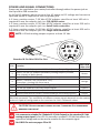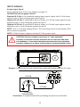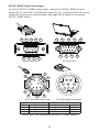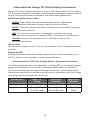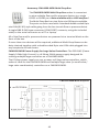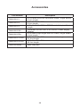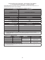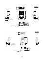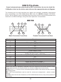
1
User’s Guide Shop online at omega.com e-mail: [email protected] For latest product manuals: omegamanual.info FLR-1600A and FLV-4600A Series XXXXXX Water Flow Meters and Controllers Xxxxx Xxxxxxxxx OMEGAnet ® Online Service omega.com Internet e-mail [email protected] Servicing North America: U.S.A.: Omega Engineering, Inc., One Omega Drive, P.O. Box 4047 Stamford, CT 06907-0047 Toll-Free: 1-800-826-6342 Tel: (203) 359-1660 FAX: (203) 359-7700 e-mail: [email protected] Canada: 976 Bergar Laval (Quebec), Canada H7L 5A1 Toll-Free: 1-800-826-6342 FAX: (514) 856-6886 ISO 9001 Certified TEL: (514) 856-6928 e-mail: [email protected] For immediate technical or application assistance: U.S.A. and Canada: Sales Service: 1-800-826-6342/1-800-TC-OMEGA® Customer Service: 1-800-622-2378/1-800-622-BEST® Engineering Service: 1-800-872-9436/1-800-USA-WHEN® Mexico: En Español: 001 (203) 359-7803 [email protected] Benelux: Managed by the United Kingdom Office Toll-Free: 0800 099 3344 TEL: +31 20 347 21 21 FAX: +31 20 643 46 43 e-mail: [email protected] Czech Republic: Frystatska 184 733 01 Karviná, Czech Republic Toll-Free: 0800-1-66342 FAX: +420-59-6311114 FAX: (001) 203-359-7807 e-mail: [email protected] Servicing Europe: France: TEL: +420-59-6311899 e-mail: [email protected] Managed by the United Kingdom Office Toll-Free: 0800 466 342 TEL: +33 (0) 161 37 29 00 FAX: +33 (0) 130 57 54 27 e-mail: [email protected] Germany/Austria: Daimlerstrasse 26 D-75392 Deckenpfronn, Germany Toll-Free: 0 800 6397678 FAX: +49 (0) 7056 9398-29 United Kingdom: ISO 9001 Certified 12/18/2014 TEL: +49 (0) 7059 9398-0 e-mail: [email protected] OMEGA Engineering Ltd. One Omega Drive, River Bend Technology Centre, Northbank Irlam, Manchester M44 5BD England Toll-Free: 0800-488-488 TEL: +44 (0)161 777-6611 FAX: +44 (0)161 777-6622 e-mail: [email protected] Rev.13 DOC-OMEGALIQMAN16 It is the policy of OMEGA Engineering, Inc. to comply with all worldwide safety and EMC/EMI regulations that apply. OMEGA is constantly pursuing certification of its products to the European New Approach Directives. OMEGA will add the CE mark to every appropriate device upon certification. The information contained in this document is believed to be correct, but OMEGA accepts no liability for any errors it contains, and reserves the right to alter specifications without notice. WARNING: These products are not designed for use in, and should not be used for, human applications. Notes for Using FLR-1600A and FLV-4600A Water Flow Devices ►► ►► ►► ►► ►► ►► USE ONLY PURE, CLEAN DI OR DISTILLED WATER IN THIS DEVICE. DO NOT use tap water or water with any biological components, minerals or oils. Any of these substances will affect the viscosity of the water (creating flow measurement inaccuracies). More importantly, these impurities will quickly build up in the laminar flow zone, cause corrosion, and render the measuring capabilities of the device useless. Pure DI water itself is corrosive to some extent, but it is the contaminants in your system that will be most detrimental to your FLR-1600A Series liquid water flow meter. If you cannot meet the requirement of pure water, then do not use this water flow device in your application. Damage caused by impurity build up is not covered by the warranty. Please read the operating manual that accompanied your device. Keep the manual for future reference. When first using the Omega water meter or controller for the day, please take the following precautions: 1. Apply your source pressure (approx. 20-30 psig for best results) to the device with the downstream flow blocked off. 2. Then slightly open both bleed ports (DO NOT completely remove the screws) and allow any trapped air to escape. Allow some flow and let water pass through while bleeding (if the unit is a controller be sure to give it at least a 50% set-point). See page 10 of the manual for more information regarding bleed ports and bleeding. 3. Try not to get any water in-between the black electronics case and the stainless steel flow body. Wipe up any excess water around these seams. 4. Tighten up both bleed screws, and then block the downstream water flow again. Visually verify zero flow through. 5. Now you can safely tare (zero) a meter (page 18) using the tare button on the device, or in the case of a water flow controller, command the zero set‑point (page 27) which will auto-tare the unit. Smooth and consistent source pressure is highly preferable, as any pulsing or fluctuation in water pressure will hydraulically couple to the differential pressure sensor, and the resultant flow reading will jump analogously. Please note that, depending on model and flow range, water flow meters have an inherent internal pressure drop higher than that of standard gas flow meters of similar flow range. The minimum water device pressure drop is 2 psig, going all the way to 20 psig drop in certain models. Your source input pressure must meet or exceed this specification, in addition to any back pressure you may have on the downstream end of your process. Please see pages 47 and 49 of the manual. Please contact Omega if you have any questions. We will be happy to help. 3 Thank you for purchasing an FLR-1600A Series Water Flow Meter or FLV‑4600A Water Flow Controller. Please take the time to find and read the information contained in this manual. This will help to ensure that you get the best possible service from your instrument. This manual covers the following instruments: FLR-1600A Series Water Flow Meters FLV-4600A Series Water Flow Controllers FLR-1600A-B Series Portable Water Meters (Note: All FLR-1600A-B Portable Water Meters operate in accordance with the instructions found in this manual. Please see page 44 for information regarding portable meter operation.) Please contact Omega if you have any questions regarding the use or operation of this device. Many Omega instruments are built for specific applications. Two instruments with the same flow range and part number may look and act quite differently depending upon the application the instrument was built for. Care should be taken when moving an instrument from one application to another. 4 TABLE OF CONTENTS GETTING STARTED MOUNTING PLUMBING PRESSURE BLEED PORTS POWER AND SIGNAL CONNECTIONS INPUT SIGNALS Analog Input Signal RS232 / RS485 Digital Input Signal OUTPUT SIGNALS RS232 / RS485 Digital Output Signal Standard Voltage (0-5 Vdc) Output Signal Optional 0-10 Vdc Output Signal Optional Current (4-20 mA) Output Signal Optional 2nd Analog Output Signal Information for Omega TFT (Color Display) Instruments DISPLAYS AND MENUS FLR-1600A Series Meters MAIN Line Absolute Pressure Line Temperature Tare Volume Flow Rate Flashing Error Message SELECT MENU COMMUNICATION SELECT Unit ID Baud MISCELLANEOUS MISC1 Zero Band Pressure Averaging Flow Averaging LCD Contrast MISC2 DIAG TEST Rotate Display MANUFACTURER DATA DISPLAYS AND MENUS FLV-4600A Series Controllers MAIN SELECT MENU CONTROL SET UP Set-Point Source Loop Variable On / Off Auto-tare PID Tuning 5 Page 7 8 8 9 10 11 12 12 13 14 14 14 15 14 14 16 17 18 18 18 18 19 19 19 20 20 20 21 21 21 21 21 21 22 22 22 23 24 25 26 27 27 28 28 29 TABLE OF CONTENTS RS232 or RS485 Output and Input Configuring HyperTerminal® Streaming Mode Tareing via RS232 / RS485 Sending a Set-point via RS232 / RS485 PID Tuning via RS232 / RS485 Changing from Streaming to Polling Mode Collecting Data Data Format Sending a Simple Script File to HyperTerminal® FLOW MEASUREMENT OPERATING PRINCIPLE TROUBLESHOOTING MAINTENANCE AND RECALIBRATION FLOW CONVERSION TABLE Option: Totalizing Mode Option: Portable Meters and Gauges Accessory: Multi-Drop Box Accessories FLR-1600A Series Technical Specifications FLV-4600A Series Specifications Eight Pin Mini-DIN Pin-Out DB15 Pin-Out Diagrams 6 Page 31 31 31 32 32 33 34 35 36 37 38 39 41 41 42 44 45 46 47 50 52 53 GETTING STARTED Power Jack 8 Pin MiniDIN Bleed Screws Display Screen Inlet Connection Port Outlet Connection Port Flow Direction Arrow FLR-1600A Water Flow Meter shown with connection port fittings Control Valve Inlet Connection Port Outlet Connection Port FLV-4600A Small Valve Water Flow Controller shown with the standard downstream valve and connection port fittings Control Valve Inlet Connection Port Outlet Connection Port FLV-4600A Large Valve Water Flow Controller shown with the standard downstream valve and connection port fittings 7 MOUNTING All FLR-1600A Series Meters and FLV-4600A Series Controllers have mounting holes for convenient mounting to flat panels. The sizes and dimensions for the mounting holes are shown on pages 47-51. Meters are position insensitive and can be mounted in any orientation. Small valve controllers can usually be mounted in any position. Large valve controllers should be mounted so that the valve cylinder is vertical. Mounting a large valve controller in another position increases the risk of leakage when the controller is being held closed by the spring force. Note: For applications that may continuously introduce occasional air bubbles to the flow stream upstream of the device, the device may be mounted upside down to prevent the bubbles from becoming trapped in the differential pressure sensor ports. If the device has been installed upside down, avoid using the bleed screws as water may leak into the electronics housing causing permanent damage that is not covered under warranty! PLUMBING Your controller is shipped with plastic plugs fitted in the port openings. To lessen the chance of contaminating the flow stream do not remove these plugs until you are ready to install the device. Make sure that the water will flow in the direction indicated by the flow arrow. Standard FLR-1600A Series Meters and FLV-4600A Series Controllers have female inlet and outlet port connections. Welded VCR and other specialty fittings may have male ports. The inlet and outlet port sizes (process connections) for different flow ranges are shown on pages 47-51. Instruments with M5 (10-32) ports have O-ring face seals and require no sealant or tape. Do not use tape with welded or o-ring fittings. For non-M5 (10-32) ports use thread sealing PTFE tape to prevent leakage around the port threads. Do not wrap the first two threads. This will minimize the possibility of getting tape into the flow stream and flow body. Do not use pipe dopes or sealants on the process connections as these compounds can cause permanent damage to the controller should they get into the flow stream. When changing fittings, carefully clean any tape or debris from the port threads. We recommend that a 20 micron filter be installed upstream of meter/ controllers with full scale ranges of 100 ccm or less and a 40 micron filter be installed upstream of meter/controllers with full scale ranges above 100 ccm. Avoiding long runs of small diameter tubing upstream or downstream of the device will reduce water hammer. 8 PRESSURE Maximum operating line pressure is 100 psig (689 kPa). If the line pressure is higher than 100 psig (689 kPa), use a pressure regulator upstream from the flow controller to reduce the pressure to 100 psig (689 kPa)or less. Although the meter’s operation is uni-directional, reversing the flow direction will inflict no damage as long as the maximum specified limits are not exceeded. The differential pressure sensor utilized in this flow meter/controller is a very sensitive device capable of detecting minute differences in pressure. Smooth and consistent source pressure is highly preferable, as any pulsing or fluctuation in water pressure will hydraulically couple to the differential pressure sensor, and the resultant flow reading will jump analogously. Please note that, depending on model and flow range, water flow meters have an inherent internal pressure drop higher than that of standard gas flow meters of similar flow range. The minimum water device pressure drop is 2 psig, going all the way to 20 psig drop in certain models. Your source input pressure must meet or exceed this specification, in addition to any back pressure you may have on the downstream end of your process. CAUTION! E�������� ��� ������� ��������� ���� �������� ��� ����� ��������� ������ �� ��� �����-����� ������������ �������� ����������. 9 BLEED PORTS FLR-1600A and FLV-4600A-Series flow meters and controllers are equipped with bleed ports on the front to aid in the removal of air bubbles from the differential pressure sensor ports. The bleed ports consist of a threaded hole with an 8-32 nylon tipped screw. After installation or anytime it is suspected that air may be trapped in the sensor ports, bleed the ports as follows: A small amount of water will leak from the device during this procedure. Take necessary precautions to prevent the leaking water from damaging anything around the unit, taking special care to avoid any live electrical devices or lines. 1. With the meter/controller installed and line pressure applied, gently loosen the upstream bleed port screw 1-2 turns or until water begins to leak from the threads. DO NOT REMOVE THE SCREW as the port is subject to line pressures and injury, equipment damage or loss of required parts may result! 2. Gently tap the flow body (a wooden or plastic screwdriver handle works well for this) to encourage air bubbles to exit the port. 3. Any air in the port will generally be removed as the water leaks out even though you may not see or hear it. 4. Gently tighten the screw until the leakage stops, taking care not to crush the nylon tip. Repeat steps 1-4 with the second bleed port. 8-32 Nylon Tipped Bleed Screw 5/64 Hex Loosen to Bleed DO NOT REMOVE! If your device is mounted in an inverted position avoid using the bleed screws as water may leak into the electronics housing causing permanent damage that is not covered under warranty! 10 POWER AND SIGNAL CONNECTIONS Power can be supplied to your meter/controller through either the power jack or the 8 pin Mini-DIN connector. An AC to DC adapter which converts line AC power to DC voltage and current as specified below is required to use the power jack. A 2.1mm, positive center, 7-30 Vdc AC/DC adapter rated for at least 100 mA is required to use the adapter jack in a FLR-1600A meter. A 2.1mm, positive center, 12-30 Vdc AC/DC adapter rated for at least 250 mA is required to use the adapter jack in a Small Valve controller. A 2.1mm, positive center, 24-30 Vdc AC/DC adapter rated for at least 500 mA is required to use the adapter jack in a Large Valve controller. NOTE: 4-20mA analog output requires at least 15 Vdc. 1 3 2 4 6 7 5 8 Standard 8 Pin Mini-DIN Pin-Out Pin Function 1 Not Connected (or optional 4-20mA Primary Output Signal) Mini-DIN cable color Black Static 5.12 Vdc [or optional Secondary Analog Output (4-20mA, Brown 5Vdc, 10Vdc) or Basic Alarm] 3 Serial RS232RX / RS485(–) Input Signal (receive) Red Meters = Remote Tare (Ground to Tare) 4 Orange Controllers = Analog Set-Point Input 5 Serial RS232TX / RS485(+) Output Signal (send) Yellow 6 0-5 Vdc (or optional 0-10 Vdc) Output Signal Green 7 Power In (as described above) Blue 8 Ground (common for power, communications and analog signals) Purple Note: The above pin-out is applicable to all the flow meters and controllers with the Mini-DIN connector. The availability of different output signals depends on the options ordered. Optional configurations are noted on the unit’s calibration sheet. 2 CAUTION! D� ��� ������� ����� �� ���� 1 ������� 6 �� ��������� ������ ��� �����! It is common to mistake Pin 2 (labeled 5.12 Vdc Output) as the standard 0-5 Vdc analog output signal. In fact Pin 2 is normally a constant 5.12 Vdc that reflects the system bus voltage and can be used as a source for the set-point signal. For DB15 Pin-outs see pages 53 to 58. 11 INPUT SIGNALS Analog Input Signal Apply analog input to Pin 4 as shown on page 11. For DB15 Pin-outs see pages 53 to 58. Standard 0-5 Vdc is the standard analog input signal. Apply the 0-5 Vdc input signal to pin 4, with common ground on pin 8. Optional 0-10 Vdc: If specified at time of order, a 0-10 Vdc input signal can be applied to pin 4, with common ground on pin 8. Optional 4-20 mA: If specified at time of order, a 4-20 mA input signal can be applied to pin 4, with common ground on pin 8. NOTE: This is a current sinking device. The receiving circuit is essentially a 250 ohm resistor to ground. NOTE: 4-20mA output requires at least 15 Vdc power input. CAUTION! D� ��� ������� ���� ������ �� “���� �������’” �������, �� ���� ���� ������� �������� �� ��� ��������� ��� ���� ��� ��������. I� ��� ���� ��������� ���� �������� ���� ������� �������, ������ ��� � ������ �������� ��� � �������� ����� ������. 8 4 Gauges: A remote tare can be achieved by momentarily grounding pin 4 to tare. 6 7 8 0-5 Vdc 3 4 5 2 1 5.12 Vdc 50 KOhm Potentiometer Controllers: A simple method for providing set-point to controllers 12 RS232 / RS485 Digital Input Signal To use the RS232 or RS485 input signal, connect the RS232 / RS485 Output Signal (Pin 5), the RS232 / RS485 Input Signal (Pin 3), and Ground (Pin 8) to your computer serial port as shown below. (See page 30 for details on accessing RS232 / RS485 input.) 5 4 9 3 8 2 1 1 7 2 3 6 6 Serial Cable End 7 4 8 5 9 PC Serial Port 1 2 4 3 5 8 7 6 8 Pin MiniDIN Cable End 8 Pin MiniDIN Connector 9 Pin Serial Connection 8 Pin MiniDIN Connection Pin Function Function Pin 5 Ground Ground 8 3 Transmit Receive 3 2 Receive Transmit 5 DB9 to Mini-DIN Connection for RS232 / RS485 Signals 13 OUTPUT SIGNALS RS232 / RS485 Digital Output Signal To use the RS232 or RS485 output signal, it is necessary to connect the RS232 / RS485 Output Signal (Pin 5), the RS232 / RS485 Input Signal (Pin 3), and Ground (Pin 8) to your computer serial port as shown on page 8. (See page 31 for details on accessing RS232 / RS485 output.) Standard Voltage (0-5 Vdc) Output Signal Meters/controllers equipped with a 0-5 Vdc (optional 0-10 Vdc) will have this output signal available on Pin 6. This output is generally available in addition to other optionally ordered outputs. This voltage is usually in the range of 0.010 Vdc for zero flow and 5.0 Vdc for full-scale flow. The output voltage is linear over the entire range. Ground for this signal is common on Pin 8. Optional 0-10 Vdc Output Signal If your meter/controller was ordered with a 0-10 Vdc output signal, it will be available on Pin 6. (See the Calibration Data Sheet that shipped with your meter to determine which output signals were ordered.) This voltage is usually in the range of 0.010 Vdc for zero flow and 10.0 Vdc for full-scale flow. The output voltage is linear over the entire range. Ground for this signal is common on Pin 8. Optional Current (4-20 mA) Output Signal If your meter/controller was ordered with a 4-20 mA current output signal, it will be available on Pin 1. (See the Calibration Data Sheet that shipped with your meter to determine which output signals were ordered.) The current signal is 4 mA at 0 flow and 20 mA at the meter’s full scale flow. The output current is linear over the entire range. Ground for this signal is common on Pin 8. (Current output units require 15-30 Vdc power.) Optional 2nd Analog Output Signal You may specify an optional 2nd analog output on Pin 2 at time of order. (See the Calibration Data Sheet that shipped with your meter to determine which output signals were ordered.) This output may be a 0-5 Vdc, 0-10 Vdc, or 4-20 mA analog signal that can represent any measured parameter. With this optional output, a meter could output the volume flow rate (0-5 Vdc on pin 6) and the line temperature (0-5 Vdc on pin 2). If your device is equipped with the optional six pin industrial connector, please contact Omega. CAUTION! D� ��� ������� ���� ������ �� “���� �������’” �������, �� ���� ���� ������� �������� �� ��� ��������� ��� ���� ��� ��������. I� ��� ���� ��������� ���� �������� ���� ������� �������, ������ ��� � ������ �������� ��� � �������� ����� ������. 14 CAUTION! D� ��� ������� ���� ������ �� “���� �������’” �������, �� ���� ���� ������� �������� �� ��� ��������� ��� ���� ��� ��������. I� ��� ���� ��������� ���� �������� ���� ������� �������, ������ ��� � ������ �������� ��� � �������� ����� ������. Purple (Ground) Red Yellow Unit A Purple Red Yellow Unit B Purple Red Unit C 4 5 2 3 1 5 3 2 Yellow 9 8 7 6 Female Serial Cable Front Typical Multiple Device (Addressable) Wiring Configuration The easiest way to connect multiple devices is with a Multi-Drop Box (see page 45). 15 Information for Omega TFT (Color Display) Instruments Omega TFT (color display) instruments have a high contrast back-lit LCD display. TFT instruments operate in accordance with Omega standard operating instructions for our monochrome menus and displays with the following differences. Multi-Color Display Color Codes: GREEN: Green labels identify the parameters and/or adjustments associated with the button directly above or below the label. WHITE: The color of each parameter is displayed in white while operating under normal conditions. RED: The color of a parameter is displayed in red when operating conditions for that parameter exceed 128% of the device’s specifications. YELLOW: Yellow is the equivalent of the selection arrow on the monochrome display. LCD Contrast: LCD contrast is ranged from 1 to 11 on color displays with 11 being the greatest contrast. Display On/Off: Pushing the button under the Omega name will turn the device display on or off. This feature is not available on monochrome displays. Technical Data for TFT (Color Display) Meters, Gauges and Controllers The following specifications are applicable to Omega TFT (color display) meters, gauges and controllers only. All other operating specifications are shown in the Technical Data page for standard Omega instruments. All standard device features and functions are available and operate in accordance with the Omega operating manual provided with the device. Specification Meter or Gauge Small Valve Controller Large Valve Controller Supply Voltage 7 to 30 Vdc 12 to 30 Vdc 24 to 30 Vdc Supply Current 80 mA @ 12Vdc 70 mA @ 24Vdc 290 mA @ 12Vdc 200 mA @ 24Vdc 780 mA @ 24Vdc 16 DISPLAYS AND MENUS FLR-1600A METERS (Displays and Menus for FLV-4600A Controllers are shown beginning page 24.) The device screen defaults to Main display as soon as power is applied to the meter. Main The Main display shows, temperature and volume flow. Line pressure will be also be displayed if the meter was order TARE V #C PSIG +21.50 +13.60 with this option. CCM Pressing the button adjacent to a . parameter will make that parameter the primary display unit. +0.000 CCM MENU By hitting the MENU button at the bottom right of the screen you will enter the Select Menu display. + Totalizer (option only) CCM +0.0 TOTAL/ TIMER 0000:00:00 BACK If your meter was ordered with the Totalizer option (page 42), pushing the TOTAL button once will bring up the Totalizing Mode display. Pushing MENU will bring up the Select Menu display. RESET CCM MENU Select Menu MISC MFG DATA RS232 COMM Select Menu From Select Menu you can interact with your RS232 / RS485 settings or read manufacturer’s data. Push MAIN to return to the Main display. MAIN 17 MAIN #C +21.50 PSIG +13.60 + CCM . +0.000 CCM LN-UP TARE V MENU LN-DN MODE >#C #K #F #R CANCEL SET This mode defaults on power up, with flow as the primary displayed parameter. The following parameters are displayed in the Main mode. Line Pressure: Only on units equipped with the optional pressure sensor, pressing the PSIG button will move the line gauge pressure to the primary display. Line Temperature: Pressing the °C button will move the process temperature to the primary display. Pushing the button again allows you to select 0C (Celsius), 0K (Kelvin), 0F (Fahrenheit) or 0R (Rankine) for the temperature scale. To select a temperature scale, use the LN‑UP and LN-DN buttons to position the arrow in front of the desired scale. Press SET to record your selection and return to the MAIN display. The selected temperature scale will be displayed on the screen. Tare: Pushing the TARE V button tares the flow meter and provides it with a reference point for zero flow. This is an important step in obtaining accurate measurements. It is best to zero the flow meter each time it is powered up. If the flow reading varies significantly from zero after an initial tare, give the unit a minute or so to warm up and re-zero it. If possible, zero the unit near the expected operating pressure by positively blocking the flow downstream of the flow meter prior to pushing the TARE button. Zeroing the unit while there is any flow will directly affect the accuracy by providing a false zero point. If in doubt about whether a zero flow condition exists, remove the unit from the line and positively block both ports before pressing the TARE button. If the unit reads a significant negative value when removed from the line and blocked, it was given a false zero. It is better to zero the unit at atmospheric pressure and a confirmed no flow condition than to give it a false zero under line pressure. It is not uncommon for a meter to read a small value when it is removed from the process line as water can “hang” in one or both of the differential pressure sensor ports. If the unit reads a significant negative value when removed from the line and blocked, it is a good indication that it was given a false zero. 18 Volume: The volume flow rate is defaulted on the primary display. Press the unit of measure button (ccm in the example above) to return the volume flow rate to the primary display. MENU: Pressing MENU switches the screen to the Select Menu display. Flashing Error Message: An error message ( VOV = volumetric overrange, POV = pressure overrange, TOV = temperature overrange) flashes when a measured parameter exceeds the range of the sensor. When any item flashes, neither the flashing parameter nor the flow measurement is accurate. Reducing the value of the flashing parameter to within specified limits will return the unit to normal operation and accuracy. If the unit does not return to normal operation contact Omega. SELECT MENU From Select Menu you can interact with your RS232 / RS485 settings or read manufacturer’s data. Press the button next to the desired operation to bring that function to the screen. MODEL INFO MISC1 MISC2 BACK BACK MAIN UNIT ID A BAUD 19200 BACK MAIN MAIN Manufacturer Data Communication Select Miscellaneous MISC MFG DATA RS232 COMM #C +21.50 PSIA +13.60 MAIN + TARE V . +0.000 CCM Select Menu MAIN Main An explanation for each screen can be found on the following pages. 19 CCM COMMUNICATION SELECT UNIT ID A BAUD 19200 BACK MAIN UNIT ID C UP DN C BACK RESET A SET BAUD DN UP Access Communication Select by pressing the button above RS232 COMM or RS485 COMM on the Select Menu display. Unit ID – Valid unit identifiers are the letters A-Z and @. The identifier allows you to assign a unique address to each device so that multiple units can be connected to a single RS232 or RS485 computer port. Press UNIT ID. Use the UP and DOWN buttons to change the Unit ID. Press SET to record the ID. Press Reset to return to the previously recorded Unit ID. Any Unit ID change will take effect when Communication Select is exited. If the symbol @ is selected as the Unit ID, the device will enter streaming mode when Communication Select is exited. See RS232 Communications (page 31) for information about the streaming mode. Baud – Both this instrument and your computer must send/receive data at the same baud rate. The default baud rate for this device is 19200 baud. Press the Select button until the arrow is in front of Baud. Use the UP and DOWN buttons to select the baud rate that matches your computer. The choices are 38400, 19200, 9600, or 2400 baud. Any baud rate change will not take effect until power to the unit is cycled. 19200 BACK SET 20 MISCELLANEOUS Miscellaneous is accessed by pressing the MISC button on the Select Menu display. Next select either MISC1 or MISC2. MISC1 will display as shown at left. ZERO BAND refers to Display Zero Deadband. Zero deadband is a value below which the display PRESS ZERO FLOW AVG BAND AVG jumps to zero. This deadband is often desired to prevent electrical noise from showing up on the display as minor flows or pressures that do not exist. Display Zero Deadband does not affect the LCD analog or digital signal outputs. BACK MAIN CONTRAST ZERO BAND can be adjusted between 0 and 3.2% of the sensor’s Full Scale (FS). Press ZERO BAND. Then use SELECT to choose the digit with the arrow and the UP and DOWN buttons to change the value. Press SET to record your value. Press CLEAR to return to zero. DOWN UP SELECT Pressure Averaging and Flow Averaging may be useful to make it easier to read and interpret rapidly fluctuating pressures and flows. Pressure and flow averaging can be adjusted between 1 (no averaging) and 256 (maximum averaging). CANCEL SET CLEAR These are geometric running averages where the number between 1 and 256 can be considered roughly equivalent to the response time constant in milliseconds. This can be effective at “smoothing” high frequency process oscillations such as those caused by diaphragm pumps. Press PRESS AVG. Then use SELECT to choose the digit with the arrow and the UP and DOWN buttons to change the value. Press SET to record your value. Press CLEAR to return to zero. Press FLOW AVG. Then use SELECT to choose the digit with the arrow and the UP and DOWN buttons to change the value. Press SET to record your value. DOWN UP Press CLEAR to return to zero. Setting a higher number will equal a smoother display. LCD CONTRAST: The display contrast can be adjusted between 0 and 30, with zero being the CANCEL SET RESET lightest and 30 being the darkest. Use the UP and DOWN buttons to adjust the contrast. Press SET when you are satisfied. Press CANCEL to return to the MISC display. > 0.0 11 21 DIAG TEST BACK SCROLL R8: AP Sig R9: Temp Sig R10: DP Side R11: DP Brdg R13: AP Brdg R16: Meter Fun R18: Power Up BACK ROTATE DISP MAIN 7871 39071 9986 36673 36673 199 32768 MAIN MISC2 will display as shown at left. Press ROTATE DISP and SET to Inverted 180° if your device is inverted. The display and buttons will rotate together. If the device has been installed upside down, avoid using the bleed screws as water may leak into the electronics housing causing permanent damage that is not covered under warranty! DIAG TEST: This diagnostic screen displays the initial register values configured by the factory, which is useful for noting factory settings prior to making any changes. It is also helpful for troubleshooting with Alicat customer service personnel. Select the DIAG TEST button from the MISC2 screen to view a list of select register values. Pressing the SCROLL button will cycle the display through the register screens. An example screen is shown at left. 22 MANUFACTURER DATA Manufacturer Data is accessed by pressing the MFG DATA button on the Select Menu display. The initial display shows the name and telephone number of the manufacturer. MODEL INFO OMEGA Ph 800-826-6342 Fax 203-359-7700 BACK MAIN1 Press MODEL INFO to show important information about your flow meter including the model number, serial number, and date of manufacture. Press BACK to return to the MFG DATA display. Push MAIN to return to the Main display. MODEL: FLR-1600A-10SLPM-D SERIAL NO: 80003 DATE MFG: 10/7/2014 DATE CAL: 10/9/2014 CAL BY: DL SW REV: 2V62 BACK MAIN 23 DISPLAYS AND MENUS FLV-4600A CONTROLLERS (Displays and Menus for FLR-1600A Meters are shown beginning page 17.) The device screen defaults to Main display as soon as power is applied to the controller. Main #C +21.50 PSIA +13.60 SETPT 0.000 + . CCM +0.000 CCM MENU The Main display shows, temperature and volume flow. Line pressure will be also be displayed if the meter was order with this option. Pressing the button adjacent to a parameter will make that parameter the primary display unit. By hitting the MENU button at the bottom right of the screen you will enter the Select Menu display. Totalizer (option only) TOTAL/ TIMER CCM +0.0 SETPT 0000:00:00 BACK If your controller was ordered with the Totalizer option (page 42), pushing the TOTAL button once will bring up the Totalizing Mode display. Pushing MENU will bring up the Select Menu display. RESET CCM MENU Select Menu MISC MFG DATA CONTROL SETUP RS232 COMM Select Menu From Select Menu you can interact with your RS232 / RS485 settings, read manufacturer’s data or access the control set-up display. Push MAIN to return to the Main display. MAIN 24 MAIN #C +21.50 PSIG +13.60 + . SETPT 0.000 CCM This mode defaults on power up, with flow as the primary displayed parameter. The following parameters are displayed in the Main mode. Line Pressure: Only on units equipped with the optional pressure sensor, pressing the PSIG button will move the line gauge pressure to the primary display. Line Temperature: Pressing the °C button will move the process temperature to the primary display. Set Point: The set-point (SETPT)is shown in the upper right of the display. For information on changing the set-point see SETPT SOURCE, page 27. +0.000 CCM MENU Volume: The volume flow rate is defaulted on the primary display. Press the unit of measure button (ccm in the example above) to return the volume flow rate to the primary display. MENU: Pressing MENU switches the screen to the Select Menu display. Flashing Error Message: An error message ( VOV = volumetric overrange, POV = pressure overrange, TOV = temperature overrange) flashes when a measured parameter exceeds the range of the sensor. When any item flashes, neither the flashing parameter nor the flow measurement is accurate. Reducing the value of the flashing parameter to within specified limits will return the unit to normal operation and accuracy. If the unit does return to normal operation contact Omega. 25 SELECT MENU From Select Menu you can interact with your RS232 / RS485 settings, read manufacturer’s data and access the control setup screen. Press the button next to the desired operation to bring that function to the screen. MODEL INFO Omega MISC1 Ph 80 0-826-6342 Fax 20 3-359-7700 MISC2 BACK BACK MAIN UNIT ID A BAUD 19200 BACK MAIN MAIN Manufacturer Data Communication Select Miscellaneous MISC MFG DATA RS232 COMM #C +21.50 PSIG +13.60 Select Menu CONTROL SETUP MAIN + . +0.000 CCM LOOP VAR ON AUTO PID SETPT MAIN +0.00 Control Setup An explanation for each screen can be found on the following pages: Control Setup: Please see page 27. Communication Select: Please see page 20. Miscellaneous: Please see page 21. Manufacturer Data: Please see page 22. 26 CCM MAIN Main SETPT SOURCE SETPT 0.000 CONTROL SETUP Control Setup is accessed by pressing the button below Control Setup on the Select Menu display. From this screen you can select your set-point source, choose a loop variable and adjust the PID terms. Press BACK to return to the Select Menu display. Press MAIN to return to the MAIN display SETPT LOOP SETPT SETPT SOURCE – Pressing the button VAR +0.0 SOURCE above SETPT SOURCE will allow you to select how the set point will be conveyed to your controller. Use the line-up and line-down buttons to move the arrow in front of the desired ON option. Then press SET. AUTO MAIN PID Press CANCEL to return to the previous display. The controller will ignore any set-point except that of the selected set-point source and it will remember which input is selected even if the power is disconnected. LN-DN LN-UP >RS232 FRONT PANEL ANALOG MODE RS232 (or RS485) refers to a remote digital RS232 / RS485 set-point applied via a serial connection to a computer or PLC as described in the installation and RS232 / RS485 sections of this manual. Front Panel refers to a set-point applied directly at the controller. Front Panel input must be selected prior to changing the set-point at CANCEL SET the device. Analog refers to a remote analog setpoint applied to Pin 4 of the Mini-DIN connector as described in the installation section of this manual. The standard analog input is 0-5 Vdc. To determine what type of analog set-point your controller has, refer to the Calibration Data Sheet that was included with your controller. If nothing is connected to Pin 4, and the controller is set for analog control, the device will generate random set-point values. NOTE: If your controller has the IPC (Integrated Potentiometer Control) option, the IPC dial will operate with the ANALOG set-point source selected. SETPT refers to the set-point. This parameter may be changed using the display only if FRONT PANEL is selected as the Input. Press SETPT. Then use SELECT to choose the decimal with the arrow and the UP and DOWN buttons to change the value. Press SET to record your value. Press CLEAR to return to zero. 27 CAUTION! N���� ����� � C��������� ���� � ���-���� ���-����� �� �� �������� �� ��������� �� ���� ����. T�� ���������� ���� ����� ���� ����� �� ��� ����� �� �� ������� �� ����� ��� ���-�����. W��� ����� �� �� ����, ���� ��� ���� ��� ����� ���� HOT! CONTROL SETUP (continued) SETPT SOURCE LOOP VAR SETPT +0.0 ON AUTO PID MAIN LOOP VAR—Water flow controllers are defaulted to volume flow. Volume means that the controller is “closing the loop” on the volume flow rate. This means that when you give the controller a set-point, the controller compares that set-point to the measured volume flow rate and adjusts the valve to try to make the flow and the set-point match. For the volume flow rate, the input signal (e.g. 0-5 Vdc) corresponds to the full-scale flow rate for the device. ON AUTO / OFF AUTO—refers to the standard auto-tare or “auto-zero” feature. LN-UP LN-DN MODE > Volumetric Flow CANCEL SET The auto-tare feature automatically tares (takes the detected signal as zero) the unit when it receives a zero set-point for more than two seconds. A zero set-point results in the closing of the valve and a known “no flow” condition. This feature makes the device more accurate by periodically removing any cumulative errors associated with drift. It is recommended that the controller be left in the default auto-tare ON mode unless your specific application requires that it be turned off. 28 PID TUNING SETPT SOURCE LOOP VAR SETPT +0.0 ON AUTO PID MAIN LN-DN MODE LN-UP >PD PID PD2I PID CANCEL SET P 00100 I 00000 D 02501 BACK LOOP TYPE MAIN PID Values determine the performance and operation of your proportional control valve. These terms dictate control speed, control stability, overshoot and oscillation. All units leave the factory with a generic tuning designed to handle most applications. If you encounter issues with valve stability, oscillation or speed, fine tuning these parameters may resolve the problem. FLR-1600A-Series controllers allow you to adjust the Proportional, Integral and Differential terms of the PID control loop. To change the PID loop parameters, push the button below PID. Press LOOP TYPE. Then use the LN-UP and LN-DN buttons to select the appropriate PID control algorithm. Press SET. See the following page for descriptions of the PID Loop Types (PID Control Algorithms). P refers to the Proportional term of the PID loop. I refers to the Integral term of the PID loop. D refers to the Differential term of the PID loop. Press P, I or D. Then use SELECT to choose the decimal with the arrow and the UP and DOWN buttons to change the value. Press SET to record your value. Press CLEAR to return to zero. Before changing the P, I or D parameter, please record the initial value so that it can be returned to the factory setting if necessary. Valve tuning can be complex. If you would like assistance, please contact Omega for technical support. 29 The PD algorithm is the PID algorithm used on most FLV-4600A controllers. It is divided into two segments: The first compares the process value to the set-point to generate a proportional error. The proportional error is multiplied by the ‘P’ gain, with the result added to the output drive register. The second operates on the present process value minus the process value during the immediately previous evaluation cycle. This ‘velocity’ term in multiplied by the ‘D’ gain, with the result subtracted from the output drive register. The above additions to and subtractions from the output drive register are carried over from process cycle to process cycle, thus performing the integration function automatically. Increasing the ‘P’ gain will promote the tendency of the system to overshoot, ring, or oscillate. Increasing the ‘D’ gain will reduce the tendency of the system to overshoot. The PD2I algorithm is a PID algorithm used primarily for high performance pressure and flow control applications. It exhibits two basic differences from the PD algorithm that most controllers utilize. 1. Instead of applying a damping function based upon the rate of change of the process value, it applies a damping function based upon the square of the rate of change of the process value. 2. The damping function is applied directly to the proportional error term before that term is used in the proportional and integral functions of the algorithm. This provides a certain amount of ‘look ahead’ capability in the control loop. Because of these differences, you will note the following: 1. Increasing ‘P’ gain can be used to damp out overshoot and slow oscillations in pressure controllers. You will know that ‘P’ gain is too high, when the controller breaks into fast oscillations on step changes in set-point. On flow controllers, too high a ‘P’ gain results in slower response times. Too low a ‘P’ gain results in overshoot and/or slow oscillation. A good starting value for ‘P’ gain is 200. 2. If the unit was originally shipped with the PD2I algorithm selected, the ‘D’ gain value should be left at or near the factory setting because it relates primarily to the system phase lags. If you are changing from the default algorithm to the PD2I algorithm, you should start with a ‘D’ gain value of 20. 3. The ‘I’ gain is used to control the rate at which the process converges to the set-point, after the initial step change. Too low a value for ‘I’ gain shows up as a process value that jumps to near the set-point and then takes awhile to converge the rest of the way. Too high a value for ‘I’ gain results in oscillation. A good starting value for the ‘I’ gain is 200. 30 RS232 / RS485 Output and Input Configuring HyperTerminal®: 1. Open your HyperTerminal® RS232 / RS485 terminal program (installed under the “Accessories” menu on all Microsoft Windows® operating systems). 2. Select “Properties” from the file menu. 3. Click on the “Configure” button under the “Connect To” tab. Be sure the program is set for: 19,200 baud (or matches the baud rate selected in the RS232 / RS485 communications menu on the meter) and an 8-N-1-None (8 Data Bits, No Parity, 1 Stop Bit, and no Flow Control) protocol. 4. Under the “Settings” tab, make sure the Terminal Emulation is set to ANSI or Auto Detect. 5. Click on the “ASCII Setup” button and be sure the “Send Line Ends with Line Feeds” box is not checked and the “Echo Typed Characters Locally” box and the “Append Line Feeds to Incoming Lines” boxes are checked. Those settings not mentioned here are normally okay in the default position. 6. Save the settings, close HyperTerminal® and reopen it. Streaming Mode (RS485 units do not have a streaming mode) In the default Polling Mode, the screen should be blank except the blinking cursor. In order to get the data streaming to the screen, hit the “Enter” key several times to clear any extraneous information. Type “*@=@” followed by “Enter” (or using the RS232 / RS485 communication select menu, select @ as identifier and exit the screen). If data still does not appear, check all the connections and COM port assignments. Streaming Mode – Advanced The streaming data rate is controlled by register 91. The recommended default rate of data provision is once every 50 milliseconds and this is suitable for most purposes. If a slower or faster streaming data rate is desired, register 91 can be changed to a value from 1 millisecond to 65535 milliseconds, or slightly over once every minute. Below approximately 40 milliseconds, data provision will be dependent upon how many parameters are selected. Fewer data parameters can be streamed more quickly than more. It is left to the user to balance streaming speed with number of parameters streamed. To read register 91, type “*r91” followed by “Enter”. To modify register 91, type “*w91=X”, where X is a positive integer from 1 to 65535, followed by “Enter”. To return to the recommended factory default streaming speed, type “*w91= 50”. 31 Tareing via RS232 / RS485 (FLR-1600A Series only): Tareing (or zeroing) the flow meter provides it with a reference point for zero flow. This is a very simple but important step in obtaining accurate measurements. It is good practice to “zero” the flow meter each time it is powered up. If the flow reading varies significantly from zero after an initial tare, give the unit a minute or so to warm up and re-zero it. If possible, it is helpful to zero the unit near the expected operating pressure by positively blocking the flow downstream of the flow meter prior to entering the Tare command. Zeroing the unit while there is any flow will directly affect the accuracy by providing a false zero point. If in doubt about whether the flow is positively blocked, remove it from the line and positively block both ports before entering the Tare command. If the unit reads a significant negative value when removed from the line and blocked, it is a good indication that it was given a false zero. It is better to zero the unit at atmospheric pressure and a confirmed no flow conditions than to give it a false zero under line pressure. To send a Tare command via RS232 / RS485, enter the following strings: In Polling Mode: Address$$V<Enter> (e.g. B$$V<Enter>) Sending a Set-point via RS232 / RS485: To send a set-point via RS232 / RS485, “Serial” must be selected under the “Input” list in the control set up mode. Method 1: Set-point may be set in floating point in serial communication using serial command (UnitID)SX.YZ Example: AS4.54 results in Unit ID A changing set-point to 4.54. Method 2: Type in a number between 0 and 65535 (2% over range), where 64000 denotes full-scale flow rate, and hit “Enter”. The set-point column and pressure rates should change accordingly. If they do not, try hitting “Enter” a couple of times and repeating your command. The formula for performing a linear interpolation is as follows: Value = (Desired Set-point X 64000) / Full Scale Flow Range For example, if your device is a 500 ccm full-scale unit and you wish to apply a set-point of 125 ccm you would enter the following value: 16000 = (125 ccm X 64000) / Full Scale Flow Range If the controller is in polling mode as described in Changing from Streaming Mode to Polling Mode, the set-point must be preceded by the address of the controller. For example, if your controller has been given an address of D, the set-point above would be sent by typing: D16000 followed by “Enter” 32 To adjust the Proportional and Differential (P&D) terms via RS232 / RS485 (FLV-4600A Series only): Type *@=A followed by “Enter” to stop the streaming mode of information. To adjust the “P” or proportional term of the PID controller, type *R21 followed by “Enter”. The computer will respond by reading the current value for register 21 between 0-65535. It is good practice to write this value down so you can return to the factory settings if necessary. Enter the value you wish to try by writing the new value to register 21. For example, if you wished to try a “P” term of 220, you would type *W21=220 followed by “Enter” where the bold number denotes the new value. The computer will respond to the new value by confirming that 21=220. To see the effect of the change you may now poll the unit by typing A followed by “Enter”. This does an instantaneous poll and returns the values once. You may type A “Enter” as many times as you like. Alternately, you could resume streaming mode by typing *@=@ followed by “Enter”. Repeat step 3 to remove the unit from the streaming mode. To adjust the “D” or proportional term of the PID controller, type *R22 followed by “Enter”. The computer will respond by reading the current value for register 22 between 0-65535. It is good practice to write this value down so you can return to the factory settings if necessary. Enter the value you wish to try by writing the new value to register 22. For example, if you wished to try a “D” term of 25, you would type *W22=25 followed by “Enter” where the bold number denotes the new value. The computer will respond to the new value by confirming that 22=25. To see the effect of the change you may now poll the unit by typing A followed by “Enter”. This does an instantaneous poll and returns the values once. You may type A “Enter” as many times as you like. Alternately you could resume streaming mode by typing *@=@ followed by “Enter”. Repeat. You may test your settings for a step change by changing the set-point. To do this type A32000 (A is the default single unit address, if you have multiple addressed units on your RS232 / RS485 line the letter preceding the value would change accordingly.) followed by “Enter” to give the unit a ½ full scale set-point. Monitor the unit’s response to the step change to ensure it is satisfactory for your needs. Recall that the “P” term controls how quickly the unit goes from one set-point to the next, and the “D” term controls how quickly the signal begins to “decelerate” as it approaches the new set-point (controls the overshoot). 33 Changing From Streaming to Polling Mode: When the meter is in the Streaming Mode (RS485 units do not have a streaming mode), the screen is updated approximately 10-60 times per second (depending on the amount of data on each line) so that the user sees the data essentially in real time. It is sometimes desirable, and necessary when using more than one unit on a single RS232 line, to be able to poll the unit. In Polling Mode the unit measures the flow normally, but only sends a line of data when it is “polled”. Each unit can be given its own unique identifier or address. Unless otherwise specified each unit is shipped with a default address of capital A. Other valid addresses are B thru Z. Once you have established communication with the unit and have a stream of information filling your screen: 1. Type *@=A followed by “Enter” (or using the RS232 / RS485 communication select menu, select A as identifier and exit the screen) to stop the streaming mode of information. Note that the flow of information will not stop while you are typing and you will not be able to read what you have typed. Also, the unit does not accept a backspace or delete in the line so it must be typed correctly. If in doubt, simply hit enter and start again. If the unit does not get exactly what it is expecting, it will ignore it. If the line has been typed correctly, the data will stop. 2. You may now poll the unit by typing A followed by “Enter”. This does an instantaneous poll of unit A and returns the values once. You may type A “Enter” as many times as you like. Alternately you could resume streaming mode by typing *@=@ followed by “Enter”. Repeat step 1 to remove the unit from the streaming mode. 3. To assign the unit a new address, type *@=New Address, e.g. *@=B. Care should be taken not to assign an address to a unit if more than one unit is on the RS232 / RS485 line as all of the addresses will be reassigned. Instead, each should be individually attached to the RS232 / RS485 line, given an address, and taken off. After each unit has been given a unique address, they can all be put back on the same line and polled individually. 34 Collecting Data: The RS232 / RS485 output updates to the screen many times per second. Very short-term events can be captured simply by disconnecting (there are two telephone symbol icons at the top of the HyperTerminal® screen for disconnecting and connecting) immediately after the event in question. The scroll bar can be driven up to the event and all of the data associated with the event can be selected, copied, and pasted into Microsoft® Excel® or other spreadsheet program as described below. For longer term data, it is useful to capture the data in a text file. With the desired data streaming to the screen, select “Capture Text” from the Transfer Menu. Type in the path and file name you wish to use. Push the start button. When the data collection period is complete, simply select “Capture Text” from the Transfer Menu and select “Stop” from the sub-menu that appears. Data that is selected and copied, either directly from HyperTerminal® or from a text file can be pasted directly into Excel®. When the data is pasted it will all be in the selected column. Select “Text to Columns...” under the Data menu in Excel® and a Text to Columns Wizard (dialog box) will appear. Make sure that “Fixed Width” is selected under Original Data Type in the first dialog box and click “Next”. In the second dialog box, set the column widths as desired, but the default is usually acceptable. Click on “Next” again. In the third dialog box, make sure the column data format is set to “General”, and click “Finish”. This separates the data into columns for manipulation and removes symbols such as the plus signs from the numbers. Once the data is in this format, it can be graphed or manipulated as desired. For extended term data capture see: “Sending a Simple Script to HyperTerminal®” on page 37. 35 Data Format: The data stream on the screen represents the flow parameters of the main mode in the units shown on the display. For FLR-1600A Series Flow Meters, there are three columns of data. The first column is line pressure (normally in psig and only in units equipped with the optional pressure sensor), the second column line temperature (normally in °C), and the third column is the volume flow rate in the units specified at time of order and shown on the display. +014.70 +014.70 +014.70 +014.70 +014.70 +014.70 +025.00 +025.00 +025.00 +025.00 +025.00 +025.00 +4.123 +4.123 +4.123 +4.123 +4.124 +4.125 FLR-1600A Series Water Flow Meter Data Format For FLV-4600A Series Flow Controllers, there are four columns of data representing pressure, temperature, volume flow and set-point. The first column is line pressure (normally in psig and only in units equipped with the optional pressure sensor), the second column is temperature (normally in °C), the third column is volume flow rate (in the units specified at time of order and shown on the display), and the fourth column is the set-point (also in the units specified at time of order and shown on the display). For instance, if the meter was ordered in units of ccm, the display on the meter would read 2.004 ccm and the last two columns of the output below would represent volume flow and set-point in ccm respectively. +014.70 +014.70 +014.70 +014.70 +014.70 +014.70 +025.00 +025.00 +025.00 +025.00 +025.00 +025.00 +02.004 +02.005 +02.006 +02.005 +02.004 +02.004 02.004 02.004 02.004 02.004 02.004 02.004 FLV-4600A Series Water Flow Controller Data Format Note: On units with the totalizer function a fourth column (meters) or fifth column (controllers) will show the totalizer value 36 Sending a Simple Script File to HyperTerminal® It is sometimes desirable to capture data for an extended period of time. Standard streaming mode information is useful for short term events, however, when capturing data for an extended period of time, the amount of data and thus the file size can become too large very quickly. Without any special programming skills, you can use HyperTerminal® and a text editing program such as Microsoft® Word® to capture text at defined intervals. 1. Open your text editing program, MS Word for example. 2. Set the cap lock on so that you are typing in capital letters. 3. Beginning at the top of the page, type A<Enter> repeatedly. If you’re using MS Word, you can tell how many lines you have by the line count at the bottom of the screen. The number of lines will correspond to the total number of times the flow device will be polled, and thus the total number of lines of data it will produce. For example: A A A A A A will get a total of six lines of data from the flow meter, but you can enter as many as you like. The time between each line will be set in HyperTerminal. 4. When you have as many lines as you wish, go to the File menu and select save. In the save dialog box, enter a path and file name as desired and in the “Save as Type” box, select the plain text (.txt) option. It is important that it be saved as a generic text file for HyperTerminal to work with it. 5. Click Save. 6. A file conversion box will appear. In the “End Lines With” drop down box, select CR Only. Everything else can be left as default. 7. Click O.K. 8. You have now created a “script” file to send to HyperTerminal. Close the file and exit the text editing program. 9. Open HyperTerminal and establish communication with your flow device as outlined in the manual. 10. Set the flow device to Polling Mode as described in the manual. Each time you type A<Enter>, the meter should return one line of data to the screen. 11. Go to the File menu in HyperTerminal and select “Properties”. 12. Select the “Settings” tab. 37 13. Click on the “ASCII Setup” button. 14. The “Line Delay” box is defaulted to 0 milliseconds. This is where you will tell the program how often to read a line from the script file you’ve created. 1000 milliseconds is one second, so if you want a line of data every 30 seconds, you would enter 30000 into the box. If you want a line every 5 minutes, you would enter 300000 into the box. 15. When you have entered the value you want, click on OK and OK in the Properties dialog box. 16. Go the Transfer menu and select “Send Text File…” (NOT Send File…). 17. Browse and select the text “script” file you created. 18. Click Open. 19. The program will begin “executing” your script file, reading one line at a time with the line delay you specified and the flow device will respond by sending one line of data for each poll it receives, when it receives it. You can also capture the data to another file as described in the manual under “Collecting Data”. You will be simultaneously sending it a script file and capturing the output to a separate file for analysis. FLOW MEASUREMENT OPERATING PRINCIPLE All FLR-1600A or FLV-4600A Series Water Flow Meters/Controllers accurately determine the flow rate by creating a pressure drop across a unique internal restriction, known as a Laminar Flow Element (LFE), and measuring differential pressure across it. The restriction is designed so that the water molecules are forced to move in parallel paths along the entire length of the passage; hence laminar (streamline) flow is established for the entire range of operation of the device. Unlike other flow measuring devices, in laminar flow meters the relationship between pressure drop and flow is linear. In order to have an accurate reading of the flow rate, the absolute viscosity of the fluid must be established. The rate at which liquids change viscosity with changes in temperature is not linear. The relationship between temperature and viscosity for water is well established and FLR-1600A and FLV-4600A Series units utilize a high accuracy temperature sensor and this relationship to provide an accurate viscosity reference. For this reason, these meters and controllers are generally recommended only for use with pure water. Any additives to water (such as antifreeze or disinfectants) that might affect the viscosity should be avoided. 38 TROUBLESHOOTING Display does not come on or is weak. Check power and ground connections and supply voltage. Please reference the technical specifications (page 47-51) to assure you have the proper power for your model. Flow reading is approximately fixed either near zero or near full scale regardless of actual line flow. Differential pressure sensor may be damaged. A common cause of this problem is instantaneous application of high pressure as from a snap acting solenoid valve upstream of the meter. If you suspect that your pressure sensor is damaged please discontinue use of the device and contact Omega. Displayed volumetric flow, pressure or temperature is flashing and message VOV, POV or TOV is displayed: Our flow meters and controllers display an error message (VOV = volumetric overrange, POV = pressure overrange, TOV = temperature overrange) when a measured parameter exceeds the range of the sensors in the device. When any item flashes on the display, neither the flashing parameter nor the flow measurement is accurate. Reducing the value of the flashing parameter to within specified limits will return the unit to normal operation and accuracy. If the unit does not return to normal contact Omega. Meter reads negative flow when there is a confirmed no flow condition. This is an indication of an improper tare. If the meter is tared while there is flow, that flow is accepted as zero flow. When an actual zero flow condition exists, the meter will read a negative flow. Simply re-tare at the confirmed zero flow condition. Also note that while the meter is intended for positive flow, it will read negative flow with reasonable accuracy (it is not calibrated for bi‑directional flow) and no damage will result. See TARE page 18. After installation, there is no flow. FLV-4600A Series controllers incorporate normally closed valves and require a set-point to operate. Check that your set-point signal is present and supplied to the correct pin and that the correct set-point source is selected under the SETPT SOURCE list in the control set up display (page 26). Also check that the unit is properly grounded. My controller does not respond to the set-point. Check that your set-point signal is present and supplied to the correct pin and that the correct set-point source is selected under the SETPT SOURCE list in the control set up display (page 27). Also check that the unit is properly grounded. The flow lags below the set-point. Be sure there is enough pressure available to make the desired flow rate. If either the set-point signal line and/or the output signal line is relatively long, it may be necessary to provide heavier wires (especially ground wiring) to negate voltage drops due to line wire length. An inappropriate PID tuning can also cause this symptom if the D term is too large relative to the P term (page 28). 39 Meter does not appear to be accurate when compared against another valid measurement of the physical flow (such as weight over time). Water flow meters can normally be compared against one another provided there are no leaks between the two meters. One common cause of inaccuracy, inconsistency, or unusual readings is air bubbles trapped in one or both of the legs of the differential pressure sensor. Bleed the ports as described in this manual to remove this possibility (See page 10). Another possibility is that the water has some contaminant or additive, such as antifreeze, that affects the viscosity of the water. A third possibility is an improper tare error (see page 18). Controller is slow to react to a set-point change or imparts an oscillation to the flow. An inappropriate PID tuning can cause these symptoms. Use at conditions considerably different than those at which the device was originally set up can necessitate a re-tuning of the PID loop (page 29). Flow flutters or is jumpy. The meters are very fast and will pick up any actual flow fluctuations such as from a diaphragm pump, etc. Also, inspect the inside of the upstream connection for debris such a PTFE tape shreds. Note: FLR-1600A & FLV-4600A Series devices feature a programmable geometric running average (GRA) that can aid in allowing a rapidly fluctuating flow to be read. Please see “Pressure Averaging” and “Flow Averaging” on page 21. The output signal is lower than the reading at the display. This can occur if the output signal is measured some distance from the meter as voltage drops in the wires increase with distance. Using heavier gauge wires, especially in the ground wire, can reduce this effect. My controller oscillates wildly and/or exhibits very different reactions to the setpoint than I expect. Conditions considerably different than those at which the device was originally set up can necessitate a re-tuning of the PID loop. Avoid long runs of small diameter tubing in the system, increase line size. RS232 / RS485 Serial Communications is not responding. Check that your meter is powered and connected properly. Be sure that the port on the computer to which the meter is connected is active. Confirm that the port settings are correct per the RS232 / RS485 instructions in this manual (Check the RS232 / RS485 communications select screen for current meter readings). Close HyperTerminal® and reopen it. Reboot your PC. See pages 12, 13 and 31 for more information on RS232 / RS485 signals and communications. Slower response than specified. FLR-1600A Series Meters and FLV-4600A Series Controllers feature a programmable Geometric Running Average (GRA). Depending on the full scale range of the meter, it may have the GRA set to enhance the stability/readability of the display, which would result in slower perceived response time. Please see “Pressure Averaging” and “Flow Averaging” on page 21. 40 Jumps to zero at low flow. FLR-1600A Series Meters and FLV-4600A Series Controllers feature a programmable zero deadband. The factory setting is usually 0.5% of full scale. This can be adjusted between NONE and 3.2% of full scale. See page 21. MAINTENANCE AND RECALIBRATION General: FLR-1600A and FLV-4600A Series Water Flow Meters and Controllers require minimal maintenance. The primary cause of damage and/or long-term inaccuracy in these devices is contamination and/or corrosion damage. Water should be filtered for particulates or biological materials that may grow in the device. When removing these units from the line for any extended period of time, make an effort to remove all of the water from the device, as deposits of calcium or other soluble minerals can affect the accuracy of the device. Recalibration: The recommended period for recalibration is once every year. A label located on the back of the device lists the most recent calibration date. The device should be returned to the factory for recalibration within one year from the listed date. Before calling to schedule a recalibration, please note the serial number on the back of the meter. The Serial Number, Model Number, and Date of Manufacture are also available on the Model Info screen (page 23). Cleaning: FLR-1600A and FLV-4600A Series Flow Meters/Controllers require no periodic cleaning. If necessary, the outside of the meter can be cleaned with a soft dry cloth. Avoid excess moisture or solvents. For repair, recalibration or recycling of this product, contact Omega. Flow Conversion Table: CCM CCH LPM LPH CFM CFH CFH 0.0021 0.00003 2.1189 0.035 60.0 1.0 CFM LPH LPM CCH CCM 0.000035 0.06 0.001 60.0 1.0 0.0000005 0.001 0.000017 1.0 0.0167 0.035 60.0 1.0 60000.0 1000.0 0.00059 1.0 0.0166 1000.0 16.667 1.0 1699.0 28.316 1699011.0 28317.0 0.0166 28.316 0.4719 28317.0 471.947 41 Option: Totalizing Mode - Controllers Controllers can be purchased with the Totalizing Mode option. This option adds an additional mode screen that displays the total flow (normally in the units of the main flow screen) that has passed through the device since the last time the totalizer was cleared. The Totalizing Mode screen is accessed by pushing the TOTAL button on the MAIN display. TOTAL/TIMER: Pushing the TOTAL/TIMER button will cycle the large numbers on the display between total mass and time elapsed. TOTAL/ TIMER SETPT +123.4 SCCM +123.4 00123.45 Batch Done 00123.45 0000:09:59 BATCH RESET SCC MENU Rollover – The customer can also specify at the time of order what the totalizer is to do when the maximum count is reached. The following options may be specified: No Rollover – When the counter reaches the maximum count it stops counting until the counter is cleared. Rollover – When the counter reaches the maximum count it automatically rolls over to zero and continues counting until the counter is cleared. Rollover with Notification – When the counter reaches the maximum count it automatically rolls over to zero, displays an overflow error, and continues counting until the counter is cleared. TOTAL MASS: The counter can have as many as seven digits. At the time of order, the customer must specify the range. This directly affects the maximum count. For instance, if a range of 1/100ths of a liter is specified on a meter which is totalizing in liters, the maximum count would be 99999.99 liters. If the same unit were specified with a 1 liter range, the maximum count would be 9999999 liters. ELAPSED TIME: The small numbers below the mass total show the elapsed time since the last reset in hours, minutes and seconds. The maximum measurable elapsed time is 9999 hours 59 minutes 59 seconds. The hours count resets when RESET is pushed, an RS232 or RS485 clear is executed or on loss of power. Press ELAPSED TIME to show this as the primary display. SETPT: Pushing SETPT will allow you to change the controller's set-point. RESET – The counter can be reset to zero at any time by pushing the RESET button. To clear the counter via RS232 or RS485, establish serial communication with the meter or controller as described in the RS232 or RS485 section of the manual. To reset the counter, enter the following commands: In Polling (addressable) Mode: Address$$T <Enter> (e.g. B$$T <Enter>) 42 BATCH PROCESSING MODE – CONTROLLERS ONLY Batch mode is a function within the optional Totalizing mode. Batch mode is designed to provide repeatable, finite flow quantities. DOWN UP SELECT DIGIT 00123.45 ˄ BACK/ CANCEL CLEAR SET To activate Batch Mode: Press BATCH. Then use SELECT DIGIT to move the arrow to the desired digit, and the UP and DOWN buttons to change the value. Press CLEAR to return to zero. Press SET to record your value. If the controller has a non-zero Set-Point, flow will start immediately. If not, press SETPT to select a Set-Point. Batch values can also be established via RS232/RS485 communication using Register 92. (See RS232/RS485 Section of this manual for serial communication methods.) Note: While the Totalizer counter will still reset across power cycles, the Batch process value is stored in EEPROM and will remain valid until updated by the user. While the Batch is processing, the desired Batch value is displayed above the totalizing counter on the Totalizer screen. Time elapsed during the Batch processing is displayed below the totalizing counter. Press TOTAL/TIMER to toggle these values. When the active Totalizer reaches the preset Batch value, flow ceases, and the display updates to “Batch Done”. The Totalizer timer also pauses. TOTAL/ TIMER SETPT 123.4 SCCM +123.4 00123.45 Batch Done 00123.45 0000:09:59 BATCH RESET SCC MENU - To start a new batch of the same size, simply press RESET. The Totalizer can reproduce any number of fixed Batches in this manner. - To start a smaller batch, decrease the Batch value. The new batch begins when you press RESET. - To continue the existing batch to a larger total volume, increase the Batch value. Flow resumes as soon as you press OK in the Batch Value screen. - To start a larger batch from scratch, first clear the flow Set-Point to zero to prevent unwanted flow. Then increase the Batch value, and select a flow Set-Point. Flow will begin when you press SET in the Set-Point screen. - To cancel a batch in progress, clear the Set-Point and press SET. Note: Batch mode operates independently of the desired flow rate, but requires a non-zero flow rate to run. The rate of flow is determined by the controller Set-Point value, which is established by the user via analog, front panel or serial communication methods. Batches can be produced more slowly or more rapidly as determined by the user-selected Set-Point flow rate. To turn off Batch Mode: Set the Batch value to zero (0.0) via the front panel or RS232/RS485 communication using Register 92. If there is a non-zero flow SetPoint, flow will immediately resume, and the Totalizer counter will continue per the user established Set-Point flow rate. 43 Omega Portable Meters and Gauges Omega Rechargeable Flow Meters and Pressure Gauges use a Li-Ion 3.7V cell located in the top section of the device. The Li-Ion cell must not be removed. Normal battery life of a fully-charged cell is 18 hours with a monochrome display or 5 hours with a TFT color display, when the backlight is set to 10. Dimming the backlight will increase battery life. The battery can be charged through either the micro-USB port or the mini-DIN connector. When the device is connected to external power it will function normally while the battery is charging. Note: If the battery has no charge, a charge time of one minute will be required before the unit can be turned on. Charge rates will be fastest through the micro-USB port using the included power supply or equivalent. The device will charge fastest when it is turned off. Recharge Time: 3.5 hours with 2A USB supply. The micro-USB port is for charging purposes only. The green/red indicator LED on top of the device will light up green to indicate that the unit is charging. The green LED will turn off when the battery is charged and the power switch is turned to “I” for ON. The indicator LED flashes red when the device has about 1 hour of battery life remaining. The LED will flash red at a faster rate when the device has about 15 minutes of battery life remaining. It is highly recommended that the device be charged immediately. When the battery charge runs out, the display contrast will turn to 0 and device performance is no longer guaranteed. Output signals from the meter are passed through the mini-DIN connector on top of the device. Rechargeable battery units do not support 0-10V analog output. Receiver resistance must be below 250Ω. Turn the power switch on top of the device to “O” for OFF when it is not in use. Warning: If the device is left ON until the battery can no longer power it, the charge indicator will fall out of sync with the actual charge. The device can be re-synced by fully charging the battery once. A Battery Charge Indicator appears below Tare on the display: PSIA +13.60 #C +21.50 TARE V 80 – 95% 50 – 80% 20 – 50% +0.000 CCM +0.000 SCCM MENU TOP VIEW OF DEVICE Green = Charging Flashing Red = Low Battery +5 Vdc Charge Only On / Off I/O 5 – 20% 0 – 5% 1 3 2 4 6 7 5 8 CAUTION! D� ��� ������� �� ����� ��� ������ ������� �� ��� -10° I O 95 – 100% �� +50°C ����������� �����. I� �������� ������� ������ ���� ��� ����������� �� ������� �� ���� �����, ��� ������� �������� ���� ���� �� 0 ��� ��� �����’� ����������� �� �� ������ ����������. T�� ���� �������� ����������� ����� �� 0° �� +45°C. I� �������� ������� ������ ������������ ������� �� ���� �����, ��� ������� ���� ��� ������. 44 Accessory: FMA1600-MDB Multi-Drop Box The FMA1600-MDB Multi-Drop Box makes it convenient to wire multiple flow and/or pressure devices to a single RS232 or RS485 port. Now available with a USB interface! The Multi-Drop Box has nine 8 pin mini-DIN ports available. The ports are to be used with a standard double ended 8 pin mini-DIN (DC-62) style cable going from the box to each flow or pressure device. A single DB9 D-SUB type connector (COM PORT) connects, using the included cable, to the serial connector on a PC or laptop. All of the flow and/or pressure devices are powered via a terminal block on the front of the box. If more than nine devices will be required, additional Multi-Drop Boxes can be daisy chained together with a double ended 8 pin mini-DIN cable plugged into any receptacle on both boxes. FMA1600-MDB Power Supply for Large Valve Controllers: The PS24VHC (Power Supply 24Vdc High Current) is a 6.5Amp 24Vdc power supply designed for running multiple large controllers on a FMA1600-MDB. The 6.5Amp power supply can run as many as 8 large valve controllers, which makes it ideal for the FMA1600-MDB and multiple large valve (or small valve / large valve combination) controllers on a FMA1600-MDB. FMA1600-MDB Multi-Drop Box Ø .156 Thru 4 Places BB-9 Multi-Drop 1.55 Box 6.75 1.75 3.46 5.06 Ø .340 Thru 2 PL 6.75 Ø .175 Thru 2 PL 7.56 45 Accessories Part Number FMA1600-C1 FMA1600-C2 FMA1600-C3 FMA1600-PSU FMA1600-CRA FMA1600-C1-25FT FMA1600-C2-25FT FMA1600-MDB Description 8 Pin Male Mini-DIN connector cable, single ended, 6 foot length 8 Pin Male Mini-DIN connector cable, double ended, 6 foot length 8 Pin Male Mini-DIN to DB9 Female Adapter, 6 foot length Universal 100-240 VAC to 24 Volt DC Power Supply Adapter 8 Pin Male Right Angle Mini-Din Cable, single ended, 6 foot length 8 Pin Male Mini-DIN connector cable, single ended, 25 foot length 8 Pin Male Mini-DIN connector cable, double ended, 25 foot length Multi-Drop Box 46 Technical Data for FLR-1600A - Series Water Flow Meters 0 – 0.5 ccm Full Scale through 0 – 10 lpm Full Scale FLR-1600A-Series water flow meters read both water flow and water temperature. An optional pressure sensor is also available. Standard Specifications (Contact Omega for available options.) Performance Available Ranges Accuracy at calibration conditions after tare Repeatability Zero Shift and Span Shift Operating Range / Turndown Ratio Maximum Flow Rate Typical Response Time Warm-up Time FLR-1600A Meters 0.5 ccm to 10 lpm ± 2% Full Scale ± 2% Full Scale 0.02% Full Scale / ºCelsius / Atm 2% to 100% Full Scale / 50:1 Turndown 128% FS Measurable 20 ms (Adjustable) < 1 Second Operating Conditions Operating Temperature Maximum Pressure FLR-1600A Meters +10 to +50 ºCelsius 200 psig Mounting Attitude Sensitivity Ingress Protection Wetted Materials None IP40 302 & 303 Stainless Steel, 316L Stainless Steel, FKM. If your application demands a different material, please contact Omega. Communication / Power Monochrome LCD Display with integrated touchpad FLR-1600A Meters Simultaneously displays Flow and Temperature (optional Pressure sensor available) Digital Output Signal1 Options RS232 Serial / RS485 Serial Analog Output Signal2 Options 0-5 Vdc / 1-5 Vdc / 0-10 Vdc / 4-20 mA Optional Secondary Analog Output Signal2 Electrical Connection Options Supply Voltage Supply Current 0-5 Vdc / 1-5 Vdc / 0-10 Vdc / 4-20 mA 8 Pin Mini-DIN / 15-pin D-sub (DB15) 7-30 Vdc (15-30 Vdc for 4-20 mA outputs) 0.040 Amp 1. The Digital Output Signal communicates Flow and Temperature (optional Pressure sensor available) 2. The Analog Output Signal and Optional Secondary Analog Output Signal communicate your choice of Flow or Temperature Range Specific Specifications 0.5 ccm to 1 ccm Pressure Drop1 at FS Flow (PSID) 2.0 2 ccm to 500 ccm 2.0 1 lpm 4.0 2 lpm 5 lpm 4.0 10.0 10 lpm 20.0 FLR-1600A Meters Full Scale Flow Mechanical Dimensions Process Connections2 4.4”H x 2.4”W x 1.1”D M5 (10-32) Female Thread 4.6”H x 2.4”W x 1.1”D 1/8” NPT Female 4.7”H x 2.7”W x 1.1”D 1/4” NPT Female 5.1”H x 4.0”W x 1.6”D 1/4” NPT Female 1. Lower Pressure Drops Available, please contact Omega. 2. Compatible with Beswick®, Swagelok® tube, Parker®, face seal, push connect and compression adapter fittings. VCR and SAE connections upon request. 47 FLR-1600A: 0 - 0.5 ccm 0 - 1 ccm FLR-1600A: 0 - 2 ccm 0 - 5 ccm 0 - 10 ccm 0 - 20 ccm 0 - 50 ccm 0 - 100 ccm 0 - 200 ccm 0 - 500 ccm 0 - 1 lpm 48 FLR-1600A: 0 - 2 lpm FLR-1600A: 0 - 5 lpm 0 -10 lpm 49 Technical Data for FLV-4600A Water Flow Controllers 0 – 5 ccm Full Scale through 0 – 5 lpm Full Scale FLV-4600A Series water flow controllers display both water flow and water temperature. An optional pressure sensor is also available. Standard Specifications (Contact Omega for available options.) Performance Available Ranges Accuracy at calibration conditions after tare Repeatability Zero Shift and Span Shift Operating Range / Turndown Ratio Maximum Flow Rate Typical Response Time Warm-up Time Small Valve Controllers 5 ccm to 500 ccm Large Valve Controllers 1 lpm to 5 lpm ± 2% Full Scale ± 2% Full Scale 0.02% Full Scale / ºCelsius / Atm 2% to 100% Full Scale / 50:1 Turndown 102.4% FS Controllable 100 ms (Adjustable) < 1 Second Operating Conditions Operating Temperature Maximum Pressure Mounting Attitude Sensitivity Valve Type Ingress Protection Small Valve Controllers Large Valve Controllers +10 to +50 ºCelsius 150 psig None Mount with valve cylinder vertical & upright Normally Closed IP40 FLV-4600A: 430FR Stainless Steel, 302 & 303 Stainless Steel, 316L Stainless Steel, FKM, Perfluoroelastomer. Large Valve Controllers Add 416 Stainless Steel, Polyoxymethylene (POM). If your application demands a different material, please contact Omega. Wetted Materials Communication / Power Monochrome LCD Display with integrated touchpad Small Valve Controllers Large Valve Controllers Simultaneously displays Flow and Temperature (optional Pressure sensor available) Digital Input/Output Signal1 Options RS232 Serial / RS485 Serial Analog Input/Output Signal2 Options Optional Secondary Analog 0-5 Vdc / 1-5 Vdc / 0-10 Vdc / 4-20 mA 0-5 Vdc / 1-5 Vdc / 0-10 Vdc / 4-20 mA Input/Output Signal2 Electrical Connection Options 8 Pin Mini-DIN / 15-pin D-sub (DB15) Supply Voltage 12-30 Vdc (15-30 Vdc for 4-20 mA outputs) 24-30 Vdc Supply Current 0.250 Amp 0.750 Amp 1. The Digital Output Signal communicates Flow and Temperature (optional Pressure sensor available) 2. The Analog Output Signal and Optional Secondary Analog Output Signal communicate your choice of Flow or Temperature Range Specific Specifications Full Scale Flow Small Valve Controllers 5 ccm to 50 ccm 100 ccm 200 ccm to 500 ccm Large Valve Controllers 1 lpm 2 lpm 5 lpm Pressure Drop1 at FS Flow (PSID) Mechanical Dimensions Process Connections2 5.0 5.0 7.5 4.6”H x 3.6”W x 1.1”D 1/8” NPT Female 4.0 4.0 10.0 5.7”H x 7.7”W x 2.3”D 1/4”NPT Female 1. Lower Pressure Drops Available, please contact Omega. 2. Compatible with Beswick®, Swagelok® tube, Parker®, face seal, push connect and compression adapter fittings. VCR and SAE connections upon request. 50 FLV-4600A: 0 - 5 ccm 0 - 10 ccm 0 - 20 ccm 0 - 50 ccm 0 - 100 ccm 0 - 200 ccm 0 - 500 ccm FLV-4600A: 0 - 1 lpm 0 - 2 lpm 0 - 5 lpm 51 Eight Pin Mini-DIN Connector Pin-Outs If your Instrument was ordered with the standard Eight Pin Mini-DIN connection, please be sure to reference the following pin-out diagram. 1 3 2 4 6 7 5 8 Standard 8 Pin Mini-DIN Pin-Out Mini-DIN cable color Black Pin Function 1 Inactive (or optional 4-20mA Primary Output Signal) Static 5.12 Vdc [or optional Secondary Analog Output (4-20mA, 2 Brown 5Vdc, 10Vdc) or Basic Alarm] 3 Serial RS232RX / RS485(–) Input Signal (receive) Red Meters = Remote Tare (Ground to Tare) 4 Orange Controllers = Analog Set-Point Input 5 Serial RS232TX / RS485(+) Output Signal (send) Yellow 6 0-5 Vdc (or optional 0-10 Vdc) Output Signal Green 7 Power In (as described above) Blue Ground (common for power, digital communications, analog signals 8 Purple and alarms) Note: The above pin-out is applicable to all the flow meters and controllers with the Mini‑DIN connector. The availability of different output signals depends on the options ordered. Optional configurations are noted on the unit’s calibration sheet. 52 DB15 Pin-Outs If your instrument was ordered with a DB15 connection, be sure to check the Calibration Label on the device and reference the appropriate pin-out diagram. The following pin-out chart describes the safest and generally compatible arrangement when connecting a non-FLR-1600A-Series DB15 wire to a DB15 equipped FLR-1600A-Series. Not all features may be available between brands, but the common denominators are featured in our DB15 offerings, along with some options for customization. DB15 5 2 9 11 8 13 15 15 Male Connector Front View 2 5 8 13 11 9 Female Connector Front View Pin Number 1 2 3 4 5 6 7 Function Ground Primary Analog Signal Output Ground N/C Power Supply (+Vdc) N/C N/C Analog Tare (meters — when grounded) 8 Analog Set-Point Input (controllers) 9 Power Supply Common 10 Ground 11 Secondary Analog Signal Output / fixed 5.12Vdc 12 N/C 13 RS232 RX (receive) or RS485 – 14 Ground 15 RS232 TX (send) or RS485 + Check your device’s calibration certificate and user manual for the actual electrical input/ output requirements, as all instruments are custom configured to some extent. NOTE: Pins 1, 3, 9, 10, and 14 are connected together inside of the device and are common grounding points. N/C = Not Connected/Open (can be used for custom pin assignments – please consult factory). 53 DB15 Pin-Outs If your instrument was ordered with a DB15 connection, be sure to check the Calibration Label on the device and reference the appropriate pin-out diagram. The following pin-out chart describes the safest and generally compatible arrangement when connecting a non-FLR-1600A-Series DB15 wire to a DB15A equipped FLR-1600ASeries. Not all features may be available between brands, but the common denominators are featured in our DB15 offerings, along with some options for customization. DB15A 2 9 5 3 12 7 8 8 15 15 Male Connector Front View Pin Number 1 2 7 5 3 12 9 Female Connector Front View 4 5 6 7 Function Ground Primary Analog Signal Output Analog Tare (meters — when grounded)* Analog Set-Point Input (controllers)* Ground Power Supply Common Ground Power Supply (+Vdc) 8 RS232 Tx (send) / RS485, A (-) [receive] 3 2 9 Ground 10 N/C 11 N/C 12 Secondary Analog Signal Output / fixed 5.12Vdc* 13 N/C 14 N/C 15 RS232 Rx (receive) / RS485, A (+) [send] Check your device’s calibration certificate and user manual for the actual electrical input/ output requirements, as all instruments are custom configured to some extent. * Added to allow for full use of features on FLR-1600A-Series devices, may not be present on host wiring NOTE: Pins 1, 4, 5, 6 and 9 are connected together inside of the device and are common grounding points. N/C = Not Connected/Open (can be used for custom pin assignments – please consult factory). 54 DB15 Pin-Outs If your instrument was ordered with a DB15 connection, be sure to check the Calibration Label on the device and reference the appropriate pin-out diagram. The following pin-out chart describes the safest and generally compatible arrangement when connecting a non-FLR-1600A-Series DB15 wire to a DB15B equipped FLR-1600ASeries. Not all features may be available between brands, but the common denominators are featured in our DB15 offerings, along with some options for customization. DB15B 2 9 8 5 11 14 5 8 15 15 Male Connector Front View 14 2 11 9 Female Connector Front View Pin Number 1 2 3 4 5 6 7 Function Ground Primary Analog Signal Output N/C N/C Power Supply (+Vdc) N/C N/C Analog Tare (meters — when grounded) 8 Analog Set-Point Input (controllers) 9 Power Supply Common 10 Ground 11 Secondary Analog Signal Output / fixed 5.12Vdc 12 N/C 13 N/C 14 RS232 RX (receive) or RS485 – 15 RS232 TX (send) or RS485 + Check your device’s calibration certificate and user manual for the actual electrical input/ output requirements, as all instruments are custom configured to some extent. NOTE: Pins 1, 9, and 10 are connected together inside of the device and are common grounding points. N/C = Not Connected/Open (can be used for custom pin assignments – please consult factory). 55 DB15 Pin-Outs If your instrument was ordered with a DB15 connection, be sure to check the Calibration Label on the device and reference the appropriate pin-out diagram. The following pin-out chart describes the safest and generally compatible arrangement when connecting a non-FLR-1600A-Series DB15 wire to a DB15B equipped FLR-1600ASeries. Not all features may be available between brands, but the common denominators are featured in our DB15 offerings, along with some options for customization. DB15K 2 9 5 13 7 8 8 14 Male Connector Front View Pin Number 1 2 3 4 5 6 7 8 9 10 11 12 13 7 5 2 14 13 9 Female Connector Front View Function N/C Primary Analog Signal Output N/C N/C Power Supply Common N/C Power Supply (+Vdc) Analog Tare (meters — when grounded) Analog Set-Point Input (controllers) Secondary Analog Signal Output / fixed 5.12Vdc * N/C Ground Ground RS232 RX (receive) or RS485 – * 14 RS232 TX (send) or RS485 + * 15 Ground Check your device’s calibration certificate and user manual for the actual electrical input/ output requirements, as all instruments are custom configured to some extent. NOTE: Pins 5, 11, 12 and 15 are connected together inside of the device and are common grounding points. N/C = Not Connected/Open (can be used for custom pin assignments – please consult factory). * Added to allow for full use of features on FLR-1600A-Series devices, may not be present on host wiring. 56 DB15 Pin-Outs If your instrument was ordered with a DB15 connection, be sure to check the Calibration Label on the device and reference the appropriate pin-out diagram. The following pin-out chart describes the safest and generally compatible arrangement when connecting a non-FLR-1600A-Series DB15 wire to a DB15B equipped FLR-1600ASeries. Not all features may be available between brands, but the common denominators are featured in our DB15 offerings, along with some options for customization. DB15H 2 10 6 11 7 14 7 15 15 Male Connector Front View 2 6 14 11 10 Female Connector Front View Pin Number 1 2 3 4 5 6 7 8 9 10 11 12 13 Function N/C RS232 RX (receive) or RS485 – * N/C N/C Ground Primary Analog Signal Output Power Supply Common N/C N/C Secondary Analog Signal Output / fixed 5.12Vdc * Power Supply (+Vdc) Ground N/C Analog Tare (meters — when grounded) 14 Analog Set-Point Input (controllers) 15 RS232 TX (send) or RS485 + * Check your device’s calibration certificate and user manual for the actual electrical input/ output requirements, as all instruments are custom configured to some extent. NOTE: Pins 5, 11, 12 and 15 are connected together inside of the device and are common grounding points. N/C = Not Connected/Open (can be used for custom pin assignments – please consult factory). * Added to allow for full use of features on FLR-1600A-Series devices, may not be present on host wiring. 57 DB15 Pin-Outs If your instrument was ordered with a DB15 connection, be sure to check the Calibration Label on the device and reference the appropriate pin-out diagram. The following pin-out chart describes the safest and generally compatible arrangement when connecting a non-FLR-1600A-Series DB15 wire to a DB15B equipped FLR-1600ASeries. Not all features may be available between brands, but the common denominators are featured in our DB15 offerings, along with some options for customization. DB15S 2 9 8 11 12 13 2 8 14 14 Male Connector Front View 13 12 11 9 Female Connector Front View Pin Number 1 2 3 4 5 6 7 Function Ground Primary Analog Signal Output N/C N/C Ground N/C N/C Analog Tare (meters — when grounded) 8 Analog Set-Point Input (controllers) 9 Power Supply Common 10 Ground 11 Secondary Analog Signal Output / fixed 5.12Vdc * 12 RS232 RX (receive) or RS485 – * 13 Power Supply (+Vdc) 14 RS232 TX (send) or RS485 + * 15 Ground Check your device’s calibration certificate and user manual for the actual electrical input/ output requirements, as all instruments are custom configured to some extent. NOTE: Pins 1, 5, 9, 10 and 15 are connected together inside of the device and are common grounding points. N/C = Not Connected/Open (can be used for custom pin assignments – please consult factory). * Added to allow for full use of features on FLR-1600A-Series devices, may not be present on host wiring. 58 WARRANTY/DISCLAIMER OMEGA ENGINEERING, INC. warrants this unit to be free of defects in materials and workmanship for a period of 13 months from date of purchase. OMEGA’s WARRANTY adds an additional one (1) month grace period to the normal one (1) year product warranty to cover handling and shipping time. This ensures that OMEGA’s customers receive maximum coverage on each product. If the unit malfunctions, it must be returned to the factory for evaluation. OMEGA’s Customer Service Department will issue an Authorized Return (AR) number immediately upon phone or written request. Upon examination by OMEGA, if the unit is found to be defective, it will be repaired or replaced at no charge. OMEGA’s WARRANTY does not apply to defects resulting from any action of the purchaser, including but not limited to mishandling, improper interfacing, operation outside of design limits, improper repair, or unauthorized modification. This WARRANTY is VOID if the unit shows evidence of having been tampered with or shows evidence of having been damaged as a result of excessive corrosion; or current, heat, moistur e or vibration; improper specification; misapplication; misuse or other operating conditions outside of OMEGA’s control. Components in which wear is not warranted, include but are not limited to contact points, fuses, and triacs. OMEGA is pleased to offer suggestions on the use of its various products. However, OMEGA neither assumes responsibility for any omissions or errors nor assumes liability for any damages that result from the use of its products in accordance with information provided by OMEGA, either verbal or written. OMEGA warrants only that the parts manufactured by the company will be as specified and free of defects. OMEGA MAKES NO OTHER WARRANTIES OR REPRESENTATIONS OF ANY KIND WHATSOEVER, EXPRESSED OR IMPLIED, EXCEPT THAT OF TITLE, AND ALL IMPLIED WARRANTIES INCLUDING ANY WARRANTY OF MERCHANTABILITY AND FITNESS FOR A PARTICULAR PURPOSE ARE HEREBY DISCLAIMED. LIMITATION OF LIABILITY: The remedies of purchaser set forth herein are exclusive, and the total liability of OMEGA with respect to this order, whether based on contract, warranty, negligence, indemnification, strict liability or otherwise, shall not exceed the purchase price of the component upon which liability is based. In no event shall OMEGA be liable for consequential, incidental or special damages. CONDITIONS: Equipment sold by OMEGA is not intended to be used, nor shall it be used: (1) as a “Basic Component” under 10 CFR 21 (NRC), used in or with any nuclear installation or activity; or (2) in medical applications or used on humans. Should any Product(s) be used in or with any nuclear installation or activity, medical application, used on humans, or misused in any way, OMEGA assumes no responsibility as set forth in our basic WARRANTY/ DISCLAIMER language, and, additionally, purchaser will indemnify OMEGA and hold OMEGA harmless from any liability or damage whatsoever arising out of the use of the Product(s) in such a manner. RETURN REQUESTS/INQUIRIES Direct all warranty and repair requests/inquiries to the OMEGA Customer Service Department. BEFORE RETURNING ANY PRODUCT(S) TO OMEGA, PURCHASER MUST OBTAIN AN AUTHORIZED RETURN (AR) NUMBER FROM OMEGA’S CUSTOMER SERVICE DEPARTMENT (IN ORDER TO AVOID PROCESSING DELAYS). The assigned AR number should then be marked on the outside of the return package and on any correspondence. The purchaser is responsible for shipping charges, freight, insurance and proper packaging to prevent breakage in transit. FOR WARRANTY RETURNS, please have the following information available BEFORE contacting OMEGA: 1. Purchase Order number under which the product was PURCHASED, 2. Model and serial number of the product under warranty, and 3. Repair instructions and/or specific problems relative to the product. FOR NON-WARRANTY REPAIRS, consult OMEGA for current repair charges. Have the following information available BEFORE contacting OMEGA: 1. Purchase Order number to cover the COST of the repair, 2. Model and serial number of theproduct, and 3. Repair instructions and/or specific problems relative to the product. OMEGA’s policy is to make running changes, not model changes, whenever an improvement is possible. This affords our customers the latest in technology and engineering. OMEGA is a registered trademark of OMEGA ENGINEERING, INC. © Copyright 2009 OMEGA ENGINEERING, INC. All rights reserved. This document may not be copied, photocopied, reproduced, translated, or reduced to any electronic medium or machine-readable form, in whole or in part, without the prior written consent of OMEGA ENGINEERING, INC. Where Do I Find Everything I Need for Process Measurement and Control? OMEGA…Of Course! Shop online at omega.com SM TEMPERATURE Thermocouple, RTD & Thermistor Probes, Connectors, Panels & Assemblies Wire: Thermocouple, RTD & Thermistor Calibrators & Ice Point References Recorders, Controllers & Process Monitors Infrared Pyrometers PRESSURE, STRAIN AND FORCE Transducers & Strain Gages Load Cells & Pressure Gages Displacement Transducers Instrumentation & Accessories FLOW/LEVEL Rotameters, Gas Mass Flowmeters & Flow Computers Air Velocity Indicators Turbine/Paddlewheel Systems Totalizers & Batch Controllers pH/CONDUCTIVITY pH Electrodes, Testers & Accessories Benchtop/Laboratory Meters Controllers, Calibrators, Simulators & Pumps Industrial pH & Conductivity Equipment DATA ACQUISITION Data Acquisition & Engineering Software Communications-Based Acquisition Systems Plug-in Cards for Apple, IBM & Compatibles Datalogging Systems Recorders, Printers & Plotters HEATERS Heating Cable Cartridge & Strip Heaters Immersion & Band Heaters Flexible Heaters Laboratory Heaters ENVIRONMENTAL MONITORING AND CONTROL Metering & Control Instrumentation Refractometers Pumps & Tubing Air, Soil & Water Monitors Industrial Water & Wastewater Treatment pH, Conductivity & Dissolved Oxygen Instruments M-3792/0115 M0000/0009