1
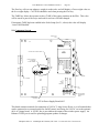
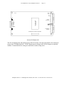
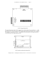
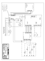
Thompson Scale Company WEIGHING SYSTEMS & PACKAGING MACHINERY CONTROLS ___________________________________________________________________________________________ 2758 Bingle Road • Houston, Texas 77055 • Phone: 713/932-9071 • Fax: 713/932-9379 Model 5511 Filler Controller User’s Manual Version 1.1 October 2011 TSC Thompson Scale Company WEIGHING SYSTEMS & PACKAGING MACHINERY CONTROLS Configure I Run Model 5511 • www.thompsonscale.com TSC Model 5511 User’s Manual Version 1.1 Page 2 Power Up of the controller displays three menu choices; configure, run and calibrate. Password protection is provided from the main screen. Press on “Model 5511” logo across the top of the screen, and options are presented for password. “Edit password to continue” is displayed, and presents two options: Enter a new password Enter a “space” character to disable password protection Selecting “enter a new password” presents a screen with a full keyboard for entry of up to 40 character password. Please note that passwords are case sensitive. If a password has been entered and is unknown, press the “Caps” key and type SCALE. Press Enter. The screen will prompt the user for a new password. Once a password has been entered, the user must enter a password to access “Configure” or “Calibrate” sections of the controller. 2.0 Configure___ _ Pressing the Configure button will present several choices: Scale Setup Set Valve Type Set UART 1 Mode Set Decimal Place Test Routines Set Time of Day Clock Thompson Scale Co. 2758 Bingle Rd. Houston, TX 77055 713-932-9071 Fax 713-932-9379 TSC Model 5511 User’s Manual Version 1.1 Page 3 2.1 Scale Setup_____ Set Display Divisions This variable sets the displayed weight in increments of either 1, 2 or 5. If set to 1, weights shown on-screen will change by 1; 50.01 to 50.02, etc. If the value is set to 2, then weight increments by 2’s; 50.02, 50.04, etc. Setting to increments of 5 will display 50.05, 50.10, 50.15, etc. The default is 1. Set Motion Band The motion band sets the amount of variance that can be seen in consecutive scale readings and still be considered to be within an acceptable range for auto zeroing. Some applications may be subject to more vibration than others, and may not be capable of capturing the necessary consecutive samples required to perform a zero if this setting is too narrow. Motion band can be set in increments from 0 to 5. The default is 2 Set Zero Range The zero range is the acceptable limit of difference between the last zero and the new displayed stable weight value that allows the scale to automatically zero the display. Select either 2%, 5% or 10%. The default is 5% Set Zero Tracking Band This setting provides a tolerance window in which zero can be tracked and still be within an acceptable range from one zero reading to the next. This variable is dependent upon the Display Divisions, and can be set from 1 to 5 display divisions. The default is 5 Set Auto Zero Time Depending upon the application, auto zero time may require a shorter or longer period of time in which to attempt to automatically zero the display. Applications with high amounts of vibration may want a lower setting, such as ¼ second, or applications that require a constant update of zero may select 0 or ¼ second. The longer the time the more difficult it is to meet the zero range and zero tracking band parameters. The default setting is ½ second. Set Auto Zero On/Off This selection toggles to On or Off only. If the function is turned off the controller will not attempt to auto zero the scale. The default is ON Set Auto TARE On/Off This function, when turned On, will automatically TARE out any weight on the scale prior to start of the fill. If this function is turned off the user can set a Container Weight value within the fill recipe. The default value for this setting is ON Thompson Scale Co. 2758 Bingle Rd. Houston, TX 77055 713-932-9071 Fax 713-932-9379 TSC Model 5511 User’s Manual Version 1.1 Page 4 2.2 Set Valve Type_____ #1 Combination Bulk and Dribble Valve This style of fill actuator requires both bulk and dribble outputs to be turned on to drive the actuator to bulk. When bulk setpoint has been reached, bulk output turns off and the dribble output remains on to the end of the fill. #2 Separate Bulk and Dribble Valves The bulk output is turned on for bulk fill. Upon reaching the bulk setpoint, the bulk output is turned off and the dribble output is turned on. #3 Separate Bulk and Dribble, but both turn on for bulk Similar to the #1 combination, but for operation of two separate actuators The default is #1 Combination 2.3 Set UART 1 Mode_____ This configuration step provides access to data output from the 5511 on serial port #1 (PORT 1) on the #810 main board. If the 5511 is configured with no settling time (see Run, then Recipe, then Timers), there is no final weight to transmit out. Setting the settling time to a value greater than 0.0 second will provide time to capture a weight value and transmit. Setting to OFF will disable the port Setting to TICKET will transmit the weight value once Setting to STREAM will send a continuous transmission of weight data Setting to MOTOR is invalid for use with a filling system BAUD rate setting offers a number of selections for transmission data rate, from as low as 1200 bits to as much as 11520 bits. The default value is Ticket at 1200 BAUD 2.4 Set Decimal Place ____ Entering this menu item will present a numeric keypad used to select either 0, 1, 2 or 3 decimal places. PLEASE NOTE: Changing this value will shift the decimal place for the Calibration test weight and for the Target and Dribble/Pre-Act values The default value is 2 Thompson Scale Co. 2758 Bingle Rd. Houston, TX 77055 713-932-9071 Fax 713-932-9379 TSC Model 5511 User’s Manual Version 1.1 Page 5 2.5 Test Routines ____ The only valid test routine is for the Input-Output test. Entering into this routine will display a row of numbers; 1 through 8, representing each input on the 811 board. A “0” shown below each of these numbers represents the state of the input. Drive the input ON, and the “0” will change to a “1” to indicate that the logic within the controller and the hardware both operate properly. Simultaneously, each output on the #811 board is turned on in sequence; 1 through 8. The output is turned on for one second, then turned off and the next output is turned on. This routine continues until exiting from the test routine 2.6 Set Time of Day Clock_____ This routine is not valid for the 5511 program 3.0 Calibrate __ __ Calibration procedure involves several steps. Please verify that the test weight value and weight conversion shown at the top of the screen is correct. The test weight used should be equal to at least ½ of the heaviest product filled on this scale and/or 10% of the scale’s full load capacity. Another reference for determining the test weight value is the change in millivolt output of the load cell. Measure the millivolt (mV) output with nothing on the scale, then apply the test weight. The mV value should change by at least 3mV. Select “No, Enter Calibration Test Weight” If the value on the top line of the display is not correct for your application. A screen with a numeric keypad is presented. Enter the correct weight value. If the weight value shows the wrong number of decimals, such as no decimals and you are trying to calibrate a 55.15 weight, you can change the decimal point, as described in the Configuration section #2, above. “Enter Test Weight Units” Presents several choices for selecting Pounds (lbs), Kilograms (kg) Ounces (oz) and Grams (g). The current weight unit is shown at the top of the screen. Selecting a different weight unit will automatically update the screen. Selecting “Yes, Continue” Will advance the display to the next screen. This prompts the operator to clear the scale from any product, bags or objects prior to advancing to the next screen. Once the scale is clear, select “Press Here When Ready” prompt. Thompson Scale Co. 2758 Bingle Rd. Houston, TX 77055 713-932-9071 Fax 713-932-9379 TSC Model 5511 User’s Manual Version 1.1 Page 6 The 5511 will display an adjustment to the scale, which determines the operating zero point of the scale. The values automatically adjust, and should result in the DAC Number being a non-zero positive value, typically between 2 and 20 counts. The OFFSET Number should also be a positive value. If not, check the scale and load cell connection. Select “Press Here to Continue” to advance the screen. The screen prompts the operator to place the test weight on the scale. Apply the test weight and select “Press Here When Ready” Adjustments are made and successful calibration is displayed. The calibration procedure is now complete and the test weight may be removed. Several errors can occur during calibration, and include: Cannot Zero Scale is typically encountered when the load cell output is at either zero millivolts or below, or is greater than 30 millivolts. Check the load cell mount for mechanical restrictions such as improperly adjusted shipping bolts within the scale, or mechanical binds caused by interference between the spout or bag post and the surrounding structure. No Test Weight on Scale is displayed if the millivolt output of the load cell when the test weight is applied is either no different than or only slightly different than the reading without the test weight applied. This usually indicates that either the test weight is too small, the load cell is damaged, or shipping links have not been removed from the scale. There should be a minimum of a 2.5mV change in the load cell output from no test weight on the filler and the load cell applied. A larger test weight may be used, which should equal at least 10% of the full load capacity of the load cell. Span at Either Min or Max indicates that the digital potentiometer used to adjust Span is either adjusted to its minimum or maximum value, and that the Span of the load cell cannot be captured. This typically indicates one of two problems. The first is that the size of test weight used in proportion to the load cell full load capacity is not adequate to induce the minimum required offset between the zero established in the first part of calibration and the current load cell reading. The controller requires a minimum of 2.5 mV offset between the zero reading and the test weight applied reading. Use of a larger test weight typically remedies the problem. The second possibility is that either the #474 card or the load cell are damaged and should be tested and/or replaced. Thompson Scale Co. 2758 Bingle Rd. Houston, TX 77055 713-932-9071 Fax 713-932-9379 TSC Model 5511 User’s Manual Version 1.1 4.0 Run Page 7 __ __ The “Run” screen is the most used screen and the controller must be in this screen to operate the filling system. 4.1 Weight & Totals Display_____ Depending upon configuration, the screen may show either one or two weight boxes at the top of the screen. Setting “Settling Time” to 0.0 will cause the filler to display only live weight, and will not provide time at the end of the fill to capture a final weight value. If “Settling Time” is set to a value greater than 0.0, two boxes will be displayed. The left box displays live weight. The right box displays captured weight from the end of the fill. In addition, the weight value can be transmitted out via the serial port on the #810 main board. Additionally, the boxes below the weight display will change. When operating with no settling time, the “Run” screen will display a single live weight box. Below this box will be two production totals; “Total Units” and “Units/Min”. These boxes are updated continuously during production. If settling time is set to more than 0.0 second, then a third box will appear to the left. This box displays a count of total weight filled during the production run. 4.2 Setting Up a Recipe_____ While in the “Run” screen, select the “Recipe” button located at the bottom left of the screen. A new screen will appear, containing the following: Target Weight Dribble Preact Container Weight Bulk/Dribble Zero Lockout Weight Timers Weight Units 4.2.1 Target Weight Select this menu item and enter the actual target weight for the fill. PLEASE NOTE that if “Container Weight” is set to 0, then the Target weight entered will be the GROSS weight for the fill (product in the bag + the bag) 4.2.2 Dribble Enter the weight value (set point) at which the filler will change from Bulk fill to Dribble fill. Thompson Scale Co. 2758 Bingle Rd. Houston, TX 77055 713-932-9071 Fax 713-932-9379 TSC Model 5511 User’s Manual Version 1.1 Page 8 4.2.3 Preact Preact is defined as the amount of scale change that occurs once bulk/dribble fill is complete. In most cases the column of product falling into the container has a positive affect on the final weight, and this value should be entered as a negative value. Other cases may require a positive Preact to reach the proper final fill weight. Set Target weight and Dribble values, as described in 4.2.1 and 4.2.2, and set Preact to 0. Fill 3 bags and note the amount of error either over or under the Target weight. Enter this value as your Preact. 4.2.4 Container Weight Gross filling systems; valve bag fillers, bulk bag fillers, drum fillers, etc. have a container placed on the scale prior to beginning the fill. The Average container weight can be entered and will be subtracted from the displayed weight at the beginning of each fill so that Net weight is displayed. If this value is set to 0, the displayed weight will show a “G” next to the weight, indicating Gross weight (product + container) is being displayed. If this value is set to a positive value greater than 0 the displayed weight will show a “N” next to the weight, indicating Net weight (subtracting container weight) If Automatic TARE has been enabled in the Scale Setup (See 2.1, above) this value will display “Auto TARE Enabled” 4.2.5 Bulk and Dribble This variable allows the user to set the filling system to run in Bulk only, Dribble only, or Bulk and Dribble. Please check your equipment to verify bulk & dribble capability. If the filler does not have dribble capability, select Bulk Only. If Bulk Only is selected, variables for “Dribble” will be removed from the recipe screen. If Dribble Only is selected, variables for “Bulk” will be removed from the recipe screen. In either case the Preact value will remain as part of the recipe. The default value is Bulk and Dribble 4.2.6 Zero Lockout Weight Output #7 is active (on) as long as weight on the scale is below the Zero Lockout Weight. When weight on the scale is equal to or larger than Zero Lockout Weight, Output #7 is deactivated (off). Zero Lockout Weight has no other interaction or purpose and will not affect fill or scale processes, unless a peripheral device is connected to and uses Output #7. Thompson Scale Co. 2758 Bingle Rd. Houston, TX 77055 713-932-9071 Fax 713-932-9379 TSC Model 5511 User’s Manual Version 1.1 Page 9 4.2.6 Timers There are three timers associated with the product recipe; discharge time, blanking time and settling time. Discharge Time Used with valve bag packers that have a bag discharge chair and can be set to a value of about 1 second to actuate the valve associated with the chair. Net weigh scales will use this value for the discharge time to open the weigh bucket. Blanking Time Is the amount of time the scale is disrupted while in transition between bulk and dribble fill. Gross fillers (air packers, impeller, auger) typically have no problem with transition from fast to slow fill, however, machinery like Net weigh scales may. Default value is 0 Settling Time Adds a short duration of time at the beginning of each fill to allow for stabilization of the scale. This same time is used at the end of each fill to capture a weight before discharge. Setting this value to 0 will result in display of live weight only and NO transmission of weight data. Caution should be used when adjusting this setting. Too short a settling time may result in inaccurate final displayed weight. Too long a settling time affects production. The default for this value is 0.5 second 4.3 Run Filler_____ Once the recipe has been created, return to the “Run” screen. The fill is started when Input #1 is driven ON. This may be by either pushbutton or a switch or input to the filler controller. The fill begins and weight data is displayed, as configured. Status prompts below the weight display alert the operator to the current status for the filler. These prompts include: “Ready” – the filler is ready to begin “Bulk” – the filler is in process of filling in bulk or fast fill “Dribble” – the filler is in process of filling in dribble or slow fill Up and down arrow adjustments in bottom right corner are provided for quickly changing the dribble set point, Preact value or the target weight. These adjusters are meant for small changes only. Press then release on the desired arrow. The associated value with go up/down with each key press. Thompson Scale Co. 2758 Bingle Rd. Houston, TX 77055 713-932-9071 Fax 713-932-9379 TSC Model 5511 User’s Manual Version 1.1 Page 10 The Zero key will zero out whatever weight is on the scale, and will display a Gross weight value on the live weight display. CAUTION should be used when pressing the Zero key. The TARE key allows the operator to take a TARE of the empty container on the filler. This value will be stored as part of the recipe and used for each new fill until changed. If Automatic TARE has been enabled in the Scale Setup (See 2.1, above) this value will display “Auto TARE Enabled” 5.0 Component Layout_____ 24VDC Output Fuse +24VDC 2 AMP 815 +5VDC 5X20 FUSE HEART BEAT CONNECTOR +3.3v J1 J2 J3 J4 J5 J6 LINE OUT J13 J12 J11 J10 J9 J8 J7 J14 SERIAL Jumper Configuration For 551 Filler DO NOT CHANGE SERIAL +24VDC 110VAC To 24VDC Switcher Connects to #811 Scale I/O Board LED Indicators To Display CPU UNIT 110VAC POWER SW1 SW2 F2 110VAC 1 AMP 3AG FUSE Line Fuse TCP/IP RJ-45 GND L2 L2 L1 OUT L1 IN Use for Optional External On/Off Switch Network Cable Connection CPU & Power Supply Board #815 This board contains terminals for connection of 110VAC 2 Amp Source Power, a set of terminals that can be connected to an external switch for On/Off control, and fusing for 110VAC out to the optional #814 AC Output board. A 24VDC fuse is provided on the output of the switcher power supply. An Ethernet TCP/IP port is used for uploading program updates or changes. Thompson Scale Co. 2758 Bingle Rd. Houston, TX 77055 713-932-9071 Fax 713-932-9379 SCALE -5V CONNECTOR PLUGS INTO 815 BOARD GND 12 +24V 11 A1 10 A0 9 8 7 6 24VDC 5 OUTPUTS 4 3 2 1 GND 10 +24V 9 8 7 6 DC SINKING 5 INPUTS 4 3 2 1 OUTPUTS +12V DEDICATED POWER SUPPLY +EX +REF +SIG -SIG -REF -EX SHIELD -12V +5V 811-A Page 11 INPUTS TSC Model 5511 User’s Manual Version 1.1 Scale & I/O Board #811 The 811 board plugs into and mounts on top of the 815 board. One end of the board is for connection to up to four 350 Ohm load cells. 24VDC Inputs must be sinking, and 24VDC Outputs are optically isolated. Terminal blocks for wiring are removable to make wiring easier. Thompson Scale Co. 2758 Bingle Rd. Houston, TX 77055 713-932-9071 Fax 713-932-9379 814 Page 12 L1 L2 8 7 6 5 4 3 2 1 TSC Model 5511 User’s Manual Version 1.1 24VDC OUTPUT CONNECTOR FROM 811 BOARD 120VAC OUTPUT CONNECTOR 110VAC Output Board #814 This optional board provides 110VAC outputs for use with existing AC powered devices. A cable runs from the #811 Scale I/O board’s 24VDC outputs and connects to this board’s lower connector. The outputs are converted to 110VAC. An indicator LED is provided for each output to provide visual indication of the output being activated. LCD MODULE 5.6" Diag. 813 DISPLAY INTERFACE CONNECTOR 1 2 3 4 5 6 7 8 SERIAL COMMUNICATIONS STATUS INDICATORS RX RX TX TX LCD Touchscreen & Interface Board #813 Thompson Scale Co. 2758 Bingle Rd. Houston, TX 77055 713-932-9071 Fax 713-932-9379 811 SCALE & I/O BOARD 12 11 10 9 8 7 6 5 4 3 2 1 10 9 10 8 9 7 8 6 7 5 6 4 5 3 4 2 3 2 OFF 1 POWER STOP START 814 24VDC TO 120VAC OUTPUT CONVERTER NEUTRAL BULK NO BY DATE DRIBBLE FILLING FILL COMPLETE BAG CHAIR 1 TSC Thompson Scale Co. ZERO LOCKOUT REVISION Thompson Scale Co. 2758 Bingle Rd. Houston, TX 77055 713-932-9071 Fax 713-932-9379 GND PRE-WIRED CABLE ON OPTIONAL 120VAC, 50/60 HZ 1 PHASE 5 AMP ISOLATED SERVICE GROUND MUST BE PROVIDED 1 2 3 4 5 6 7 8 9 12 11 10 24VDC SINKING INPUTS 24VDC OUTPUTS GROUND LOAD CELL N 815 PROCESSOR & POWER SUPPLY BOARD +EX +REF +SIG -SIG -REF -EX SHIELD L1 N 120VAC TO 24VDC SWITCHER 2FU 2 5 x 20 mm 24VDC SUPPLY PORT 0 813 DISPLAY INTERFACE 200-029 5.3" COLOR LCD W/ TOUCHSCREEN J1 = PORT 0 SET TO RS-232 JUMPER SETTINGS J8 = COLOR TOUCHSCREEN J10 = FILL PROGRAM ENABLE J12 = DWM EMULATION 1FU 1 3AG LINE OUT 1 2 3 4 5 6 7 8 1 2 3 4 5 6 7 8 Page 13 TSC Model 5511 User’s Manual Version 1.1 TSC Model 5511 User’s Manual Version 1.1 Page 14 _____Spare Parts_____ 811 Scale I/O Board 813 Display Interface Board 814 24VDC Output to 110VAC Output Expander Board 815 CPU & Power Supply Board 200-1307 Scale terminal plug, 811 board - 7 pin 200-1310 24VDC Input terminal plug, 811 board - 10 pin Also used on 814 board 200-1312 24VDC Output terminal plug, 811 board - 12 pin 204-109 Cable, 815 to 811 board 204-110 Cable, 814 to 811 board 200-1308 Communications terminal plug, 815 board – 8 pin 200-1310.1 110VAC Output terminal plug, 814 board – 10 pin 200-032-10 5x20 Glass fuse, 2 Amp for 24VDC, 815 board 200-031-10 3AG Glass fuse, 1 Amp for 110VAc, 815 board 200-059 TSC Display Overlay 200-63-10 Overlay Protector – package of 10 200-029 Color LCD Module Thompson Scale Co. 2758 Bingle Rd. Houston, TX 77055 713-932-9071 Fax 713-932-9379