1
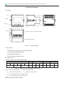
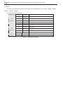
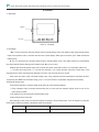
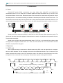
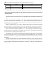
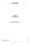
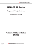
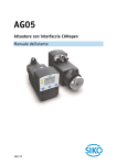
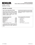
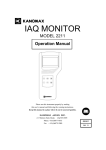
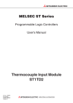
PD76-E4E-WFF Digital Indicating Panel Mounted Electrical Measuring Instruments
20
5. Communication
5.1 Forward
PD76-24C-M7F provides RS485 communication port, adopts Modbus (both Modbus-RTU and Modbus-ASCII)
communication protocol. Up to 32 meters can be connected together with single communication wire, you can set its own
communication address for each of them. Different series meter varies in the number of communication wiring terminals. it should
use twisted-pair wire for communication connecting, and diameter of the twisted-pair wire should not be less than 0.5mm2 .The
communication wire should be away from strong electric cable or strong electric field,maximal communication distance is 1200
meters,the typical wiring method is as picture 9 shown. User can also select other proper wiring method according to site situation.
k
M
k
+
M
V A W DI
V A W DI
V A varD O
V A varD O
V A
V A
Hz
Hz
PC机
...
120Ω
232转485
Picture 13
Communication connecting
Modbus protocol uses a master-slave technique, in which firstly one device (the master) initiates transactions (queries). The
other devices (the slaves) respond by supplying the requested data to the master, or by taking the action requested in the query.
The work mode is semi-duplex.
Modbus protocol only allows the communication between master(PC,PLC,etc)and slaves,and does not allow the data
exchange between independent terminal devices. As a result, the terminal devices will not use communication line when
initialization, only response the query signal.
5.2 Byte format
5.2.1 ASCII mode
When controllers are setup to communicate on a Modbus network using ASCII mode, each eight-bit byte in a message is
sent as two ASCII characters. The main advantage of this mode is that it allows time intervals of up to one second to occur
between characters without causing an error. Each transmission contains 10 bit serial data. During transmission, lower bit first,
then higher bit. User can select odd, even or without parity. The transmission sequence of both types are as follows:
D0
D1
start
止
D2
D3
D4
D6
D5
data
Picture 14 transmission sequence with parity bit(ASCII mode)
起
D0
D1
D2
D3
D4
D5
D6
D7
parity
止
start
data
end
起始位
数据位
停止位
Picture 15 transmission sequence without parity bit(ASCII mode)
end