1
Application Note 9840
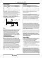
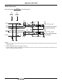
Ground Connection
RGND 0Ω
DIGITAL GROUND PLANE
TP2
ANALOG
GROUND
ANALOG GROUND PLANE
TP1
DIGITAL
GROUND
E4 E5
ICOMP1
0Ω
R56
SMA1
E6
(NOTE 3)
R22
50Ω
IOUT
0Ω
R57
SMA5
VOUT = (2 x IOUT x REQ)V
100Ω
IOUTA
SMA2
IOUTB
R61
0Ω
R25
50Ω
R51
0Ω
R31
50Ω
0Ω
R70
R52
50Ω REPRESENTS THE SPECTRUM
ANALYZER INPUT IMPEDANCE.
NOTE 2
SMA3
QOUTB
QOUTA
100Ω
R69
0Ω
SMA4
E7
QCOMP1
0.1µF
C10
50Ω
0.1µF
C4
R34
50Ω
R72
0Ω
QOUT
R71
50Ω
SMA6
VOUT = (2 x QOUT x REQ)V
50Ω IS THE SPECTRUM ANALYZER
INPUT IMPEDANCE.
E9 E8
NOTES:
1. AGND1 and DGND1 are tied together at a single point near the DAC. Optimum placement for Rgnd was found by iteration while observing the
spectral noise floor.
2. ICOMP1 and QCOMP1 MUST be tied together externally!
3. *E6 was mistakenly grounded so R56 should not be populated! E7, however, is correct and can be used to overdrive the internal reference op
amp for increasing the multiplying bandwidth.
11