1
iSync_Manual
3/18/06
10:19 AM
Page 12
Page 12 of 31
iSync HD and iSync Pro User Manual
Page 13 of 31
iSync HD and iSync Pro User Manual
Connecting iSync HD [Pro] (continued)
Connecting iSync HD [Pro] (continued)
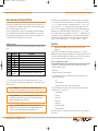
b. Connect your Analog Video Inputs
g. Set the Mode switch to Normal and apply power to your unit:
There are individual analog video inputs that are customizable for each of the following interfaces:
Once you have made all the A/V connections to your iSync HD [PRO], set the Mode switch
located on the rear panel of the unit is to the “Normal” position.
■
Component Video (YPbPr): 3 x color coded RCA female connectors
■
S-Video: 2 x S-Video connectors
■
Composite Video (CV): 3 x RCA female connectors
c. Connect your Digital Video Outputs
There is one (1) separately customizable HDMI Digital Video plug-and-play output. HDMI
supports audio and HDCP copy protection. Note the 1 x HDMI Type A 19-pin connector on
the right side of the iSync HD [Pro] rear panel.
With all equipment connected to your iSync HD [PRO]and the Mode switch in the “Normal”
position, you may now plug in the external 6 VDC @ 6 Amp Power Supply (provided with your
unit) to the jack on the back of the unit and connect the power cord into an appropriately rated
wall outlet or power strip.
You may now turn your iSync HD [PRO] unit ON using the front-panel pushbutton, the IR
Remote Control, or RS-232.
h. Set the brightness level of the iSync HD [PRO] LCD display:
If the equipment you would like to connect to your iSync HD [Pro] has only DVI-D connectors,
then you should use Key Digital® HDMI / DVI-D adapters to connect your equipment to the
iSync HD [Pro]. Note that while HDMI supports both Video and Audio over an HDMI cable,
DVI-D supports Video only and will therefore require that you connect any audio source
separately to the iSync HD [Pro].
If you feel it is necessary at this time to adjust the brightness of the LCD panel display, this can
be easily done using the adjustment tool (screwdriver) provided. The adjustment is made via
the adjustment screw opening located on the right side panel of the unit when you are facing
the front of the unit.
d. Connect your Analog Video Outputs
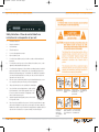
Simply insert the adjustment tool into the opening located on the right side panel of the iSync
HD [PRO] unit, and be sure the tool is in the correct position. Then, adjust the brightness by
turning the tool clockwise or counterclockwise until you are pleased with the brightness level of
the LCD display on the front of the iSync unit.
There are individual analog video outputs that are customizable for each of the following interfaces:
■
Component Video (YPbPr): 1 x color coded RCA female connectors
■
H/V Sync [composite]: RCA female connector
e. Connect your Audio Inputs and Outputs:
The iSync HD [Pro] also supports analog audio left and right audio pair inputs and output,
and SPDIF digital audio inputs and outputs.
■
Analog Stereo Left & Right Audio Input: 4 x L/R RCA female connectors
■
Analog Stereo Left & Right Audio Output: 1 x L/R RCA female connector
■
SPDIF Digital Coaxial Audio Input: 4 x RCA female connectors
■
SPDIF Digital Coaxial Audio Output: 1 x RCA female connector
■
SPDIF Optical Audio Input: 2 x Toslink
■
SPDIF Optical Audio Output: 1 x Toslink
f. Connect your RS-232 Control:
In addition to the included IR Remote Control for operation of your iSync HD [Pro], you can also
control operation of your unit via the RS-232 port available on the connector array on the back
panel of the unit.
The brightness level of the front-panel LCD can be adjusted at any time, but it is most convenient to do so before you mount or permanently install your iSync HD [PRO] unit.