1
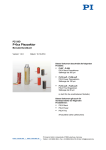
PZ178E User Manual
E-421 • E-470 • E-471 • E-472 HVPZT
Piezo Power Amplifier / Controller
Release: 1.1.0 Date: 23.10.2012
This document describes the following
product(s):
■
■
■
■
E-421.00
HVPZT Piezo Power Amplifiermodule, 1 Channel
E-470.20
HVPZT Piezo Power Amplifier/Controller, 1 Channel,
Benchtop
E-471.20
HVPZT Piezo Power Amplifier/Controller, 1 Channel, 19''
E-472.20
HVPZT Piezo Power Amplifier/Controller, 2 Channels
© Physik Instrumente (PI) GmbH & Co. KG
Auf der Römerstr. 1 ⋅ 76228 Karlsruhe, Germany
Tel. +49 721 4846-0 ⋅ Fax: +49 721 4846-1019
[email protected] ⋅ www.pi.ws
Declaration of
Conformity
according to ISO / IEC Guide 22 and EN 45014
Manufacturer:
Manufacturer´s
Address:
Physik Instrumente (PI)
GmbH & Co. KG
Auf der Römerstrasse 1
D-76228 Karlsruhe,
Germany
The manufacturer hereby declares that the product
Product Name:
Power Amplifier for HVPZT
Model Numbers:
E-470, E-471, E-472, E-421
Product Options:
all
complies with the following European directives:
73/23/EEC, Low voltage directive
89/336/EEC, EMC-Directive
The applied standards certifying the conformity are listed below.
Electromagnetic Emission:
EN 61000-6-3, EN 55011
Electromagnetic Immunity:
EN 61000-6-1
Safety (Low Voltage Directive):
EN 61010-1
February 19, 2007
Karlsruhe, Germany
Dr. Karl
Spanner
President
Physik Instrumente (PI) GmbH & Co. KG is the owner of the following company names and trademarks:
PI®
The following designations are protected company names or registered trademarks of third parties:
LabVIEW™
The products described in this manual are in part protected by the following patents:
US-Patent No. 6,950,050
Copyright 1999–2012 by Physik Instrumente (PI) GmbH & Co. KG, Karlsruhe, Germany.
The text, photographs and drawings in this manual enjoy copyright protection. With regard thereto, Physik
Instrumente (PI) GmbH & Co. KG reserves all rights. Use of said text, photographs and drawings is
permitted only in part and only upon citation of the source.
First printing 23.10.2012
Document Number PZ178E BSc, Bro, Release 1.1.0
E-47x_E-421_User_PZ178E110.doc
Subject to change without notice. This manual is superseded by any new release. The newest release is
available for download at www.pi.ws (http://www.pi.ws).
About this Document
Users of this Manual
This manual is designed to help the reader to install and operate the E-47x HVPZT Piezo Power Amplifier.
It assumes that the reader has a fundamental understanding of basic servo systems, as well as motion
control concepts and applicable safety procedures.
The manual describes the physical specifications and dimensions of the E-47x HVPZT Piezo Power
Amplifier as well as the installation procedures which are required to put the system into operation.
Conventions
The notes and symbols used in this manual have the following meanings:
WARNING
Calls attention to a procedure, practice or condition which, if not
correctly performed or adhered to, could result in injury or death.
DANGER
Indicates the presence of high voltage (> 50 V). Calls attention to a
procedure, practice or condition which, if not correctly performed or
adhered to, could result in injury or death.
CAUTION
Calls attention to a procedure, practice, or condition which, if not
correctly performed or adhered to, could result in damage to equipment.
NOTE
Provides additional information or application hints.
Any optional elements which might be mentioned in this documentation are described in their own
manuals. Current releases can be downloaded from the PI Website as PDF files (http://www.pi.ws),
obtained from your Physik Instrumente sales engineer or from [email protected] (mailto:[email protected]).
!
Contents
1
Introduction
1.1
1.2
1.3
1.4
1.5
2
Overview ........................................................................................... 3
Prescribed Use .................................................................................. 4
Safety Precautions............................................................................. 4
Model Survey and Upgrades ............................................................. 6
Unpacking ......................................................................................... 8
Operation
2.1
2.2
2.3
2.4
2.5
2.6
9
Calibrated System ............................................................................. 9
Setup ................................................................................................. 9
Front and Rear Panel Elements ....................................................... 10
Line Voltage Connection .................................................................. 11
Output Voltage Range ..................................................................... 11
Piezo Actuator Connection .............................................................. 14
2.6.1
2.6.2
2.6.3
2.7
3
Bipolar Piezo Actuators ...................................................................... 15
Unipolar Piezo Actuators .................................................................... 15
Wiring Example................................................................................... 15
Modes of Operation ......................................................................... 16
2.7.1
2.7.2
2.7.3
Open-Loop and Closed-Loop Operation ............................................ 16
Analog Operation ................................................................................ 16
Remote Control via Computer Interface ............................................. 17
2.8 Analog Control Signal ...................................................................... 17
2.9 First Operation ................................................................................. 17
2.10 Zero-Point Adjustment in Closed-Loop Operation with E-509 .......... 18
3
Maintenance
3.1
AC Power and Line Power Fuses .................................................... 21
3.1.1
3.1.2
3.2
21
Line Cord ............................................................................................ 21
Line Power Fuses ............................................................................... 21
Cleaning .......................................................................................... 22
4
Troubleshooting
23
5
Technical Data
24
5.1
5.2
Specifications .................................................................................. 24
Frequency Response Diagram ........................................................ 25
5.3
5.4
5.5
Block Diagram ................................................................................. 26
Signal Path with Servocontroller and PC-Interface Module .............. 26
Pin Assignments .............................................................................. 28
5.5.1
5.5.2
5.5.3
2-Pin High-Voltage Connector ............................................................ 28
Internal Backplane Connector of E-47x Chassis ................................ 29
E-421 Main Connector ........................................................................ 29
Introduction
1
Introduction
1.1
Overview
Figure 1: E-471 Configuration example: E-471.20 HVPZT amplifier, with optional
E-509 PZT servo-controller and E-516 interface/display module
(predecessor of the current E-517 interface and display module)
The E-470 series high-power piezo amplifiers/controllers are specifically
designed to drive high-capacitance PICA piezo actuators. They are based on
the E-421 four-quadrant amplifier module, which can output and sink a peak
current of 500 mA and an average current of 100 mA in a voltage range of 3
to 1100 V (jumper selectable bipolar range also provided). Three standard
configurations are available:
■ E-470.20 is a bench-top amplifier in a 9.5'' chassis for open-loop
operation (1 channel)
■
■
E-471.20 is the amplifier module in a 19'' rackmount chassis that can
hold additional servo-control, interface and display modules
E-472.20 is a 2-channel version in a 19'' rackmount chassis for
dynamic open-loop operation
These amplifiers can be used to drive open and closed-loop piezo
positioning systems.
www.pi.ws
E-421 • E-470 • E-471 • E-472 PZ178E Release 1.1.0
Page 3
Introduction
Open-Loop Piezo Operation
For open-loop piezo operation the amplifier output voltage is determined by
the analog signal at the Control Input combined with the DC-offset
potentiometer setting. Open-loop operation is ideal for applications where
the fastest response and the highest bandwidth are essential. Here,
commanding and reading the target position in absolute values is either not
important or carried out by an external feedback loop.
Optional Servo-Controller Upgrade
The E-471.20 version allows easy installation of an optional E-509 sensor- /
servo-controller module for closed-loop piezo position control. In this mode
the amplifier is slaved to the E-509 servo controller. Depending on the
attached piezo mechanics and feedback sensor, positioning accuracy and
repeatability in the nanometer range and below are feasible.
Computer Control
The E-517 computer interface/display module can also be installed in the
E-471 / E-472.
Optionally digital control via a D/A converter is possible. For several D/A
boards from National Instruments PI offers a corresponding LabVIEW driver
set which is compatible with the PI General Command Set (GCS), the
command set used by all PI controllers. A further option includes the
patented Hyperbit technology providing enhanced system resolution.
1.2
Prescribed Use
Based on their design and realization, E-47x HVPZT Piezo Power Amplifiers
are intended to drive capacitive loads, in the present case, piezoceramic
actuators. E-47xs must not be used for applications other than stated in this
manual, especially not for driving ohmic (resistive) or inductive loads.
Observe the safety precautions given in this User Manual.
The E-47x meets the specifications as defined by DIN EN 61010 for safe
operation under normal ambient conditions. See the specifications table for
details. (p. 24)
1.3
Safety Precautions
Carefully read also the user manuals and/or technical notes of all other
components involved, such as controllers or software.
Failure to heed warnings in this manual can result in bodily injury or material
damage or loss of warranty.
www.pi.ws
E-421 • E-470 • E-471 • E-472 PZ178E Release 1.1.0
Page 4
Introduction
DANGER—HIGH VOLTAGE
E-47x Power Amplifiers output VERY HIGH VOLTAGES and HIGH
CURRENTS which can cause death or injury!
Take special care if connecting products from other manufactures.
Follow general accident prevention rules!
Working with these devices requires adequately trained and educated
operating personnel.
During operation, do NOT touch any part which might be connected to
the HV output!
WARNING
Piezo Actuators Sensitive to Overvoltage or Reverse
Polarity
Exposing some piezo actuators to voltages too far outside their
operating range will destroy the active element in the actuator. Make
sure that both the polarity and the voltage as seen by the piezo actuator
are within the allowable range.
Be especially vigilant regarding polarity when using older actuators,
adapter cables and controllers set up for non-standard voltage ranges.
!
CAUTION
!
CAUTION—AIR CIRCULATION
www.pi.ws
Read this before operating the equipment covered in this manual.
Always keep the User Manual safe and close to the described device. In
case of loss or damage to the instructions, please order a new copy from
your PI distributor or download one from www.pi.ws (http://www.pi.ws).
Also keep and add all further information (e.g. extended instructions or
Technical Notes) to the User Manual.
Do not cover the ventilation slots on the top side of the E-47x. The
device needs to be installed horizontally with 3 cm air circulation area.
Vertical mounting prevents internal convection. Insufficient air flow will
cause overheating and premature failure.
E-421 • E-470 • E-471 • E-472 PZ178E Release 1.1.0
Page 5
Introduction
1.4
Model Survey and Upgrades
The following standard configurations of E-47x series piezo amplifiers are
available:
E-470.20
HVPZT Piezo Amplifier, 1 channel, 550 W, 1100 V,
Bench-Top, includes one E-421 piezo amplifier module
with power supply in a 9.5'' chassis
E-471.20
HVPZT Piezo Amplifier, 1 channel, 550 W, 1100 V,
Bench-Top, includes one E-421 piezo amplifier module
and power supply, upgrade with servo-controller and
interface / display module possible, 19'' ' chassis for
rackmounting
E-472.20
HVPZT Piezo Amplifier, 2 channels, 550 W, 1100 V,
Bench-Top, includes two E-421 piezo amplifier modules
and power supply (is equivalent to E-471.20 with E-421
upgrade), 19'' -chassis for rackmounting
NOTE
The content of this user manual applies only to the models listed above.
The predecessors—E-47x.00 and E-420—are no longer in production,
and this user manual is not valid for them.
The E-471.20 amplifier is upgradable with a servo-control module (E-509),
and/or a computer interface and display module (E-517, E-515 for display
only). These modules come installed directly in the chassis. If the servo
module and a piezo actuator are ordered with the system, your E-471.20 will
be fully calibrated before being shipped.
Contact your PI sales engineer or write [email protected], if you want to upgrade
your amplifier. Any additional modules are described in their own separate
manuals.
The following modules are available:
E-509.C1A,
E-509.L1,
E-509.S1
www.pi.ws
Sensor / Servo-Controller Module for capacitive, LVDT or
SGS position sensors respectively, 1 channel
to eliminate drift and hysteresis from positioning
operations.
E-421 • E-470 • E-471 • E-472 PZ178E Release 1.1.0
Page 6
Introduction
www.pi.ws
E-517.i1/.i10
Interface- / Display Module, 24 Bit D/A, TCP/IP, USB,
RS-232, .i10 only: IEEE 488; 1 Channel;
displays the current voltage and, if servo-module also
present, the position of the piezo actuator, and can also
communicate with a host PC. Dynamic link library,
LabVIEW driver set and convenient interactive user
interface software are provided.
E-515.01
Display Module for Piezo Voltage and Position, 1 channel
E-500.ACD
CD with Driver Set for Analog Controllers, available free
of charge upon request
Computer control can be implemented using a
DAC-board in a PC to generate the analog input signal. PI
offers a LabVIEW driver set which can be used with
certain D/A boards. This driver set is compatible with the
PI General Command Set (GCS) LabVIEW driver set
available for all newer controllers from PI.
The PI Analog Controller drivers support all D/A converter
boards from National Instruments that are compatible
with DAQmx8.3. LabVIEW compatibility is given from
version 7.1 upwards. Connection of a sensor monitor
signal from a sensor- or servo-module (e.g. E-509) is
required.
The driver set is also available for download from the PI
website.
E-500.HCD
Hyperbit Functionality for Enhanced System Resolution
access
PI’s patented Hyperbit technology for providing position
resolution higher than that of the D/A board is in the
E-500.ACD driver set. Activating Hyperbit requires
purchase of the password, which can be obtained from PI
under Order No. E-500.HCD.
E-421 • E-470 • E-471 • E-472 PZ178E Release 1.1.0
Page 7
Introduction
1.5
Unpacking
Unpack the E-47x HVPZT Piezo Power Amplifier with care. Compare the
contents against the items covered by the contract and against the packing
list.
The following components are included:
PZ178
User manual for E-421/E-47x.20
3763
Line cord
Inspect the contents for signs of damage. If parts are missing or you notice
signs of damage, contact PI immediately.
Save all packing materials in case the product need be shipped again.
www.pi.ws
E-421 • E-470 • E-471 •
E-472 PZ178E Release 1.1.0
Page 8
Operation
2
Operation
2.1
Calibrated System
If a controller with an included servo module is ordered together with a piezo
actuator, the system will be fully calibrated at PI according to your
specifications before being shipped, and will come with a calibration
information sheet.
CAUTION—CALIBRATION
!
Calibration should only be done by qualified authorized personnel after
consultation with PI, otherwise internal configuration data may be
destroyed by erroneous operation.
If you inform PI about your application, your E-47xs will be fully
calibrated before being shipped. It is usually not necessary for you to do
anything more than adjust the zero point before operating the system.
Do not interchange controller (whole devices or individual modules)
and/or piezo stages if they are matched and calibrated together.
Respect the assignment of the piezo actuators to the individual
controller channels, as indicated by the serial numbers on the labels
affixed to the devices. With multi-axis stages respect the channel/axis
assignments indicated by the cable labeling
2.2
Setup
!
CAUTION—AIR CIRCULATION
Do not cover the ventilation slots on the top side of the E-47x. The
device needs to be installed horizontally with 3 cm air circulation area.
Vertical mounting prevents internal convection. Insufficient air flow will
cause overheating and premature failure.
The E-471.20 and E-472.20 amplifiers are suitable for mounting in a 19''
rack. The device must be installed horizontally with 3 cm clearance for air
circulation. Do not cover the ventilation slots.
www.pi.ws
E-421 • E-470 • E-471 • E-472 PZ178E Release 1.1.0
Page 9
Operation
2.3
Front and Rear Panel Elements
DC Offset turning knob
10-turn potentiometer for DC Offset (see
"Analog Control Signal" p. 17)
"CONTROL INPUT" BNC
socket
Connection of control signal (see "Analog
Control Signal" p. 17)
"PZT HIGH VOLTAGE"
LEMO socket
High-voltage output for piezo actuator
"Power" LED
Steady green during operation
The controls of the optional servo-control (E-509) and PC interface/display
(E-517, E-515) modules are described in their own separate manuals.
The on/off switch, line voltage connection and fuses are located on the rear
panel of the device (p. 21).
www.pi.ws
E-421 • E-470 • E-471 • E-472 PZ178E Release 1.1.0
Page 10
Operation
2.4
Line Voltage Connection
Unless you request otherwise, upon delivery the E-47x will be set up for the
voltage predominant in your country, either
115 V ~ / 50-60 Hz
or
230 V ~ / 50-60 Hz
The preset voltage can be identified on the rear panel of the device (p. 21).
To adapt the E-47x to a different line voltage, the line power fuses must be
replaced. See “AC Power and Line Power Fuses” (p. 21) for instructions and
for the required fuse types.
Connect the line voltage connection on the rear panel of the device to an
appropriate power outlet via the included line cord.
2.5
Output Voltage Range
The maximum voltage swing of E-47x is 1100 V. In closed-loop operation,
10% of this maximum output is reserved for the control loop.
The default setting for the output range is 0 to +1100 V (1000 V). This setting
can be changed my moving an internal pin accessible at the rear of the E-421
piezo amplifier module.
DANGER—HIGH VOLTAGE
Disconnect from line voltage before changing the output voltage range!
NOTE
With a closed-loop system, changing the output voltage requires a new
calibration. Contact your PI representative.
To change the output voltage range, proceed as follows:
■
■
www.pi.ws
Disconnect the piezo amplifier from line voltage and wait a minute to
be sure that any residual voltage has dissipated
Remove the rear panel of the case
E-421 • E-470 • E-471 • E-472 PZ178E Release 1.1.0
Page 11
Operation
■
■
Select the desired output voltage range by re-plugging the pin (see
figure below)
For E-472: output voltage ranges of both channels can be set
independently from each other
Remount the rear panel
Figure 2: Output voltage range selection; the red pin is at the lowest (default) position
Pin position
(5) Lowest Position (default)
(4)
(3)
(2)
(1) Upper Position
Output voltage
+3 to +1100 V
-260 to +780 V
-550 to +550 V
+260 to -780 V
-3 to-1100 V
Gain Selection
For each amplifier channel the gain is set to +100 by default. Alternatively the
gain can be set to -100.
The gain of an amplifier should only be changed, if the analog Control In
signal does not match the selected output voltage range (see Section
"Analog Control Signal" (p. 17)).
To change the gain, proceed as follows:
■ Disconnect the E-47x.20 from line voltage
■
■
■
www.pi.ws
Unscrew the front panel of the respective E-421 piezo amplifier
module. Pull the amplifier module out of the chassis
Unscrew the rear panel of the E-421amplifier module and remove the
rear panel
Reverse the switch (circled in figure below)
E-421 • E-470 • E-471 • E-472 PZ178E Release 1.1.0
Page 12
Operation
■
Re-install the rear panel, put the E-421 amplifer module into the
chassis and re-fasten the module's front panel screws
Figure 3: E-421 with rear panel removed: The gain switch is circled. Default gain
setting +100
Example:
With gain set to +100 (default) and range #4 selected, an analog signal at
Control In of +2.5 to -7.5 V leads to an output voltage range of +250 to
-750 V.
www.pi.ws
E-421 • E-470 • E-471 • E-472 PZ178E Release 1.1.0
Page 13
Operation
2.6
Piezo Actuator Connection
DANGER—HIGH VOLTAGE
E-47x Power Amplifiers output VERY HIGH VOLTAGES and HIGH
CURRENTS which can cause death or injury!
Take special care if connecting products from other manufactures.
Follow general accident prevention rules!
Working with these devices requires adequately trained and educated
operating personnel.
During operation, do NOT touch any part which might be connected to
the HV output!
DANGER—IMPROPER WIRING CAN CAUSE
DEATH, INJURY, DAMAGE AND VOID
WARRANTY
Modification of HIGH VOLTAGE Connectors should only be carried out
by the manufacturer. Any unauthorized modification may jeopardize
operating personnel. Treat HIGH VOLTAGES and HIGH CURRENTS
with respect.
Connect the piezo actuator to the “PZT Out” socket of the E-47x.
If you are connecting other actuators or wiring your own connector, read the
discussion of actuator type carefully and any documentation that came with
the actuator.
WARNING
Piezo Actuators Sensitive to Overvoltage or Reverse
Polarity
Exposing some piezo actuators to voltages too far outside their
operating range will destroy the active element in the actuator. Make
sure that both the polarity and the voltage as seen by the piezo actuator
are within the allowable range.
www.pi.ws
E-421 • E-470 • E-471 • E-472 PZ178E Release 1.1.0
Page 14
Operation
Be especially vigilant regarding polarity when using older actuators,
adapter cables and controllers set up for non-standard voltage ranges.
2.6.1
Bipolar Piezo Actuators
Here the output voltage swing is so chosen that the actuator sees both
negative and positive high voltages. The output always has one lead at 0 V
(PGND), and here the other is in a zero-crossing range, commonly·±500·V.
2.6.2
Unipolar Piezo Actuators
The notation of "positive" and "negative" polarity of piezo actuators does not
refer to their direction of motion. Unipolar piezos of any polarity will elongate
when a voltage is applied.
"Positive" and "negative" refers to the sign of the voltage applied to the piezo
actuator.
For example, with an unipolar actuator with positive polarity, one terminal is
at ground potential while the high voltage of up to +1100 V is applied to the
other terminal (see "2-Pin High-Voltage Connector" S. 28).
2.6.3
Wiring Example
In the wiring example shown at right, a
"positive" piezo is connected so as to
have 0 to +1100 V applied. To achieve
this, the positive terminal (possibly
labeled "+1100 V") is connected to the
variable HV-Out and the negative
terminal to PGND.
Standard PI piezo actuators have
positive polarity and are equipped with
suitable LEMO connectors .
www.pi.ws
E-421 • E-470 • E-471 • E-472 PZ178E Release 1.1.0
Page 15
Operation
2.7
Modes of Operation
2.7.1
Open-Loop and Closed-Loop Operation
Open-Loop Operation
All E-47x versions can be operated in open-loop mode. Open-loop operation
means that any control input provided by the user determines the output
voltage directly.
Closed-Loop Operation
Closed-loop operation requires a position sensor and a servo module (e.g.
E-509). Closed-loop operation means that the user commands the piezo
excursion. The output voltage required to reach this target position is
calculated internally by the servo-loop, based on the given target and the
feedback of the position sensors (see E-509 User Manual PZ77E).
Note: In closed-loop operation up to 10% of the output range may be
required for compensating nonlinearity and drift.
2.7.2
Analog Operation
All E-47x versions can be operated by an analog control signal. Depending
on the servo mode (open-loop or closed-loop), this signal determines either
the output voltage or the position for the piezo actuator. The range of the
analog signal is to be adapted to the selected output voltage range (see
"Analog Control Signal” ( p. 17)) The analog signal consists of the following
components:
External Analog Signal
An external voltage can be applied to the "Control In" BNC socket. This
signal can be anywhere in the range of -10 to +10 V, but may not have an
active swing more than 11 V wide.
The signal can be generated using a DAC-board in a PC. PI offers a
LabVIEW driver set which can be used with certain D/A boards from National
Instruments. This driver set is compatible with the PI General Command Set
(GCS). In addition, PI’s patented Hyperbit technology for providing position
resolution higher than that of the D/A board is in this driver set (see "Model
Survey and Upgrades" p. 6).
DC Offset potentiometer
Depending on the position of the potentiometer, a DC voltage between 0 and
10 V is made available. If you require a constant DC-offset, make sure the
knob stays at the required position.
www.pi.ws
E-421 • E-470 • E-471 •
E-472 PZ178E Release 1.1.0
Page 16
Operation
2.7.3
Remote Control via Computer Interface
E-47x models equipped with an E-517 computer interface and display
module can be controlled from a host computer via a PC interface (TCP/IP,
USB, RS-232 or IEEE488). In this operating mode all analog input is ignored
(signal at "Control In", setting of the DC-offset potentiometer). If
servo-controller modules for closed-loop operation are present, all SERVO
switched must be set to "OFF". This operating mode is also referred to as
ONLINE mode, while analog operation is also referred to as OFFLINE mode.
See the E-517 User Manual for details.
2.8
Analog Control Signal
The permissible range of the analog control voltage in open-loop operation is
one-hundredth of the output voltage range. If the gain was inverted to -100,
the range of the control signal is changed accordingly too (see "Output
Voltage Range" p. 11).
The external analog signal at the "Control In" socket and the voltage
generated by the DC offset potentiometer sum up internally to the actual
analog control signal, so that the DC offset potentiometer can be used to shift
the external analog signal into the suitable range. This can be necessary to
make use of the full output voltage range.
The permissible range of the control voltage in closed-loop operation with the
E-509 sensor/servo module is 0 to 10 V.
2.9
First Operation
!
CAUTION—AIR CIRCULATION
Do not cover the ventilation slots on the top side of the E-47x. The
device needs to be installed horizontally with 3 cm air circulation area.
Vertical mounting prevents internal convection. Insufficient air flow will
cause overheating and premature failure.
The following instructions refer to Analog Operation (p. 16) of the system. If
your E-47x is equipped with an E-517 computer interface and display module
and you want to control the system via the computer interface, perform only
steps 1 and 2 of the instructions below and then operate the system as
described in the E-517 User Manual.
1
www.pi.ws
Connect the E-47x to the line voltage using the included line cord.
The connection is on the rear panel of the chassis (see "Line
Voltage Connection" p. 11)
E-421 • E-470 • E-471 •
E-472 PZ178E Release 1.1.0
Page 17
Operation
2
Connect the piezo actuator to the E-47x HV output.
For closed-loop systems (see also the E-509 User Manual):
2.1
Connect the sensor cable to the corresponding socket
2.2
If you are using the sensor monitor signal, connect your
appropriate electronics to the SENSOR MONITOR socket
2.3
Set "SERVO" toggle switch on the servo module "OFF"
3
Turn the DC offset potentiometer full counterclockwise (CCW)
4
Make sure that voltage at "Control In" is set to 0 V
5
Turn on the line power. The green "POWER" LED will light up
6
Command the first motion of the piezo actuator by turning the offset
potentiometer full clockwise (CW) to run the actuator over the
nominal travel range, then turn the potentiometer back full CCW
If an E-517 interface and display module or an E-515 display module
is installed, watch the voltage and, if an E-509 servo module is
present, the position on the display to check whether the system is
operating properly.
Make sure that the full voltage swing is attained
7
If an E-509 servo module is installed, the SENSOR MONITOR
signal will show a voltage from about 0 to 10 V proportional to the
piezo extension.
Example: A piezo actuator with a nominal travel of 100 µm shows a
sensor monitor signal of 1.5 V at 15 µm. For an actuator with 30 µm
nominal travel, 1.5 V at sensor monitor would correspond to 4.5 µm
(15% of 30 µm)
8
If you want to use an external analog signal for control, connect a
suitable signal source to the "Control In" BNC socket. The
permissible range of the analog control signal is 1/100 of the
selected output voltage range (p. 11).
If you have a closed-loop system, follow up by performing a zero-point
adjustment.
2.10 Zero-Point Adjustment in Closed-Loop
Operation with E-509
The zero-point adjustment becomes necessary when the application
conditions (particularly load, temperature) of the piezo actuator have
changed. Proper zero-point adjustment ensures that the full output voltage
www.pi.ws
E-421 • E-470 • E-471 • E-472 PZ178E Release 1.1.0
Page 18
Operation
swing can be used without reaching the output voltage limits of the amplifier
and causing an overflow condition (see E-509 user manual, PZ77E).
The adjustment can be performed in "Online" as well as in "Offline" mode (p.
17). However, "offline" and "online" modes must not be mixed during the
adjustment.
In “Online” mode with the E-517 interface and display module, zero-point
adjustment can be performed without additional equipment; see the E-517
user manual for how to proceed.
For zero-point adjustment in analog (offline) mode, the following additional
equipment is required: an adjustable voltage source which is able to output
1/100 of the selected output voltage range, and a precision voltmeter.
How to perform zero-point adjustment in "offline" mode (analog operation):
!
1
Make sure the piezo actuator is mounted in the same way and with
the same load as during normal operation in the application
2
Make sure that the external analog control signal at “Control In” is
0 V and turn the DC offset potentiometer full CCW
3
Set the SERVO toggle switch on the front panel to OFF
4
Connect a voltmeter to the SENSOR MONITOR socket
5
Power up the system
6
Turn the DC offset potentiometer full clockwise and than back full
counterclockwise (0 V) to exercise the mechanics over its full travel
range
7
Adjust the ZERO potentiometer on the E-509 module until a
sensor-monitor signal of 0 V is measured by the voltmeter on the
SENSOR MONITOR socket
8
Switch to closed-loop operation (SERVO ON)
CAUTION
If your piezo actuator starts oscillating (humming noise), turn off the
SERVO immediately! The actuator can be irreparably damaged by
resonant oscillation. Call your PI representative.
If a display module is present, the position of the piezo will now jump to "0".
Connect a voltmeter in parallel with the piezo to the "PZT Out" socket, or
watch the output voltage on the display module, if present. Adjust the ZERO
potentiometer on the E-509 module to obtain the following value for the
output voltage at the sensor zero point:
www.pi.ws
E-421 • E-470 • E-471 • E-472 PZ178E Release 1.1.0
Page 19
Operation
Selected output voltage range
Output voltage value at sensor
zero point
0 to 1000 V
50 V
-250 to +750 V
-200 V
-500 to +500 V
-450 V (positive piezo polarity)
+450 V (negative piezo polarity)
+250 to -750 V
200 V
0 to -1000 V
-50 V
This is the output voltage value corresponding to the low end of the piezo
actuator travel range.
Check the output voltage range at "PZT Out” using the voltmeter or a display
module while you command the maximum extension with either a DC voltage
of 0 to 10 V on "Control In" or by turning the DC offset potentiometer full
clockwise.
If the full output voltage range is attainable, the zero-point adjustment is
finished. If not, repeat the adjustment with a slightly different value for the
zero point.
www.pi.ws
E-421 • E-470 • E-471 • E-472 PZ178E Release 1.1.0
Page 20
Maintenance
3
Maintenance
WARNING—LINE VOLTAGE
E-47xs need to be installed in such a way that they can quickly and
easily be separated from the line voltage. Before cleaning the E-47x,
changing the AC fuses and removing or installing modules, switch the
device off and disconnect it from the line power.
3.1
AC Power and Line Power Fuses
3.1.1
Line Cord
Replace the included line cord only by a line cord with suitable rating.
3.1.2
Line Power Fuses
Unless otherwise requested, the unit will be set up for the power predominant
in your country. New line-power fuses are required when changing the
supply voltage.
!
CAUTION – DOUBLE POLE FUSE
Both fuses are active and have to be checked if there is a fault.
Figure 5: Fuse carrier
Figure 4: Position of the line fuses and fuse
carrier, only one of two fuses
visible
www.pi.ws
E-421 • E-470 • E-471 • E-472 PZ178E Release 1.1.0
Page 21
Maintenance
To access the line power fuses, proceed as follows:
1
Switch off the E-47x and remove the line cord
2
Wait at least one minute to be sure that any residual voltage has
dissipated
3
Pry open the door that covers the fuse carrier and pry out the fuse
carrier (see figures above)
4
Replace both fuses with fuses of the suitable type:
220 V AC to 240 V AC 2 x IEC * 1.25 A HT (slow blow)/250 V AC
100 V AC to 120 V AC 2 x IEC* 2.5 A HT (slow blow)/250 V AC
5
Rotate the fuse carrier so that the valid voltage setting (115 V or
230 V) will show through the window when the door is closed
6
Reinstall the carrier and close the door
NOTE
The E-472 piezo amplifier with two E-421 amplifier modules must be
supplied with the following fuses:
3.2
■
220 V AC to 240 V AC
2 x IEC* 2.5 A HT (slow blow)/250 V AC
■
100 V AC to 120 V AC
2 x IEC* 5 A HT (slow blow)/250 V AC
Cleaning
The outside surface of the case can be cleaned using mild detergents or
disinfectant solutions. Organic solvents must not be used.
*
www.pi.ws
IEC fuses are cited: other fuse standards may require higher nominal current rating
E-421 • E-470 • E-471 • E-472 PZ178E Release 1.1.0
Page 22
Troubleshooting
4
Troubleshooting
Positioner does not move.
Cables not connected properly:
■ Check the connecting cables.
■
Note the permissible voltage range for the analog control signal at
"Control In".
The permissible range of the analog control voltage is one
one-hundredth of the output voltage range (see "Analog Control
Signal" p. 17)
Still having problems? Call your local distributor or write to [email protected];
please have the following information about your system ready:
www.pi.ws
■
Product codes and serial numbers of all products in the system
■
Current firmware version of the controller
■
Software version of drivers and / or host software
■
Operating system on host PC
E-421 • E-470 • E-471 • E-472 PZ178E Release 1.1.0
Page 23
Technical Data
5
Technical Data
5.1
Specifications
E-470.20, E-471.20,
E-472.20, E-421.00
Function
Unit
Power amplifier for PICA high-voltage piezo actuators
(servo-controller and interface option for E-471)
Amplifier
Amplifier channels
3 to
(Selectable
-260 to
-550 to
+260 to
-3 to
1 (E-472: 2)
Average current
100
mA
Peak current, < 5ms
500
mA
Amplifier bandwidth, small
signal
DC to 3 kHz, related to load capacitance, see operating limits
graph
Amplifier bandwidth, large
signal
Ripple, noise
0 to 100 kHz
Current limitation
DC to 3 kHz, related to load capacitance, see operating limits
graph
<25
100 (200 nF)
Short-circuit-proof
Voltage gain
+100 ±1 (default), -100 ±1
Control input voltage
Servo off: ±1/100 of selected output range
Servo on: 0 to 10 V
100
Output voltage
Input impedance
1100 (default)
V
+780
+550
-780
-1100)
mVRMS
mVP-P
kΩ
Interfaces and operation
Piezo voltage output
LEMO EGG.0B.701.CJL1173
Control input
BNC
DC Offset
10-turn pot., adds 0 to +10 V to Control IN
Miscellaneous
Operating voltage
100 - 120 or 220 - 240 V AC, selectable (fuse change required)
Operating temperature range
+5 °C to +50 °C (above 40 °C, power derated)
Overtemp protection
Max. 75 °C, deactivation of the piezo voltage output
Mass
5.2 (E-470); 7.6 (E-471); 10.1 (E-472); 2.5 (E-421)
kg
Dimensions
236 x 132 x 296 + handles (E-470); 450 x 132 x 296 + handles
(E-471, E-472); 215 x 123 x 185 (E-421)
mm
www.pi.ws
E-421 • E-470 • E-471 • E-472 PZ178E Release 1.1.0
°C
Page 24
Technical Data
5.2
Frequency Response Diagram
Figure 6: E-421.00, operating limits with various piezo loads. Values shown are
capacitance in nanofarads
www.pi.ws
E-421 • E-470 • E-471 • E-472 PZ178E Release 1.1.0
Page 25
Technical Data
5.3
Block Diagram
Figure 7: E-421 Blockschaltbild
5.4
Signal Path with Servocontroller and
PC-Interface Module
The block diagram below shows the signal path for E-47x closed-loop
versions upgraded with an E-517 interface and display module. The E-47x
open-loop versions and models without E-517 module are equipped with
dummy modules instead. The purpose of these dummies is to complete the
internal circuitry and the front panel of the chassis.
CAUTION
If your E-47x contains dummy modules: Do not operate the E-47x when
the dummy modules are removed. Without the dummy module(s), the
system will malfunction because no Control In signal can be fed into the
amplifier module due to the broken circuit.
www.pi.ws
E-421 • E-470 • E-471 • E-472 PZ178E Release 1.1.0
Page 26
!
Technical Data
Figure 8: Interconnections between E-517 Interface, power amplifier (E-421) and
E-509 Servo-Controller
www.pi.ws
E-421 • E-470 • E-471 • E-472 PZ178E Release 1.1.0
Page 27
Technical Data
5.5
Pin Assignments
5.5.1
2-Pin High-Voltage Connector
DANGER—IMPROPER WIRING CAN CAUSE
DEATH, INJURY, DAMAGE AND VOID
WARRANTY
Modification of HIGH VOLTAGE Connectors should only be carried out
by the manufacturer. Any unauthorized modification may jeopardize
operating personnel. Treat HIGH VOLTAGES and HIGH CURRENTS
with respect.
Type: LEMO
EGG.0B.701.CJL.1173
Pin Assignments:
HV OUT: HV output, up to 1100 V
PGND: Power ground
Housing: cable shield
www.pi.ws
E-421 • E-470 • E-471 • E-472 PZ178E Release 1.1.0
Page 28
Technical Data
5.5.2
Internal Backplane Connector of E-47x Chassis
The connector behind each module slot in the E-47x chassis (on the inside of
the back panel) is for signal transmission and power supply of the module.
5.5.3
Pin
Function
4
GND (power)
6
+15 V output, 0.3 A
8
-15 V output, 0.3 A
10
+5 V output, 1.0 A
12
14
GND (measurement)
Control output
16
Piezo Monitor (0.1% of HV out)
18
Control input
20
22
Sync (-)
Sync (+)
24
Line power, 120/230 V AC common
26
n.c.
28
Line 120 V AC Phase
30
Line 230 V AC Phase
32
GND (chassis)
E-421 Main Connector
The rear connector on the E-421 amplifier module is compatible with the
corresponding sockets in the E-47x chassis. Contact PI if you need more
information for use in a different environment.
www.pi.ws
E-421 • E-470 • E-471 • E-472 PZ178E Release 1.1.0
Page 29