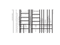
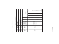
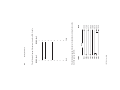
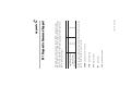
1
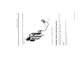
(Cat. No. 1747-KFC15)
SLC500 ControlNet
RS-232 Interface
Allen-Bradley
User
Manual
avoid the hazard
recognize the consequences
•
•
Important: Identifies information that is critical for successful application and
understanding of the product.
identify a hazard
•
Attention statements help you to:
!
ATTENTION: Identifies information about practices or
circumstances that can lead to personal injury or death, property
damage or economic loss.
Throughout this manual we use notes to make you aware of safety considerations:
Reproduction of the contents of this copyrighted publication, in whole or in part,
without written permission of Allen-Bradley Company, Inc., is prohibited.
Due to the rapid change in technology and part availability, Allen-Bradley reserves
the right to change the appearance of certain products which may not match those
shown in this manual.
Allen-Bradley publication SGI-1.1, Safety Guidelines for the Application,
Installation, and Maintenance of Solid State Control (available from your local
Allen-Bradley office), describes some important differences between solid-state
equipment and electromechanical devices that should be taken into consideration
when applying products such as those described in this publication.
The illustrations, charts, sample programs and layout examples shown in this guide
are intended solely for purposes of example. Since there are many variables and
requirements associated with any particular installation, Allen-Bradley does not
assume responsibility or liability (to include intellectual property liability) for
actual use based upon the examples shown in this publication.
Because of the variety of uses for the products described in this publication, those
responsible for the application and use of this control equipment must satisfy
themselves that all necessary steps have been taken to assure that each application
and use meets all performance and safety requirements, including any applicable
laws, regulations, codes and standards.
Important User Information
understand how the KFC15 module communicates on the
network (procedures and protocols)
troubleshoot for problems
•
•
1747-5.34 - June 1998
install and configure the KFC15 module
•
Throughout this manual we refer to the 1747-KFC15 Communication
Interface as the KFC15 module. Use this manual to:
Purpose of the Manual
The 1747-KFC15 allows an SLC500 modular processor to
communicate with the ControlNet™ network via the processor’s
RS-232 serial port.
Preface
1786-6.21
AG-2.2
1770-4.1
1747-5.27
Allen-Bradley ControlNet Cable System
Planning and Installation Manual
Allen-Bradley ControlNet Cable System
Component List
Allen-Bradley Industrial Automation Wiring
and Grounding Guidelines
SLC 5/03 and 5/04 Modular Processors
Installation Instructions
Allen-Bradley high voltage ac and dc type repeaters (1786-RPT and
1786-RPTD)
Allen-Bradley PLC-5® processors (1785-L20C15, -L40C15,
-L60C15, and -L80C15)
Allen-Bradley computer interface cards (1784-KTC15 and
1784-KTCX15)
Allen-Bradley 1794 FLEX I/O Adapters (1794-ACN15 and
1794-ACRN15)
Allen-Bradley 1771 I/O Adapters (1771-ACN15 and 1771-ACNR15)
•
•
•
•
•
1747-5.34 - June 1998
Allen-Bradley ControlNet taps (1786-TPR, 1786-TPS, 1786-TPYR
and 1786-TPYS)
•
The KFC15 module creates an interface between the ControlNet network
and an SLC500 processor. It has been verified to work with the following
products:
Related Products
Publication Number
Publication
The following publications contain information related to the KFC15
module:
Related Publications
P-2
Network Access cable (1786-CP)
•
The data transmission in one direction at a time, usually
point-to-multipoint.
Half Duplex
1747-5.34 - June 1998
The ability to simultaneously send/receive data between devices,
point-to-point.
Full Duplex
Allen-Bradley’s RS-232 proprietary protocol.
DF1
The communication architecture that allows the exchange of messages
between devices that follow the ControlNet specifications. ControlNet is
a real-time, control-layer network that provides high-speed transport for
both time-critical I/O and message data. A ControlNet network can be
either single or redundant media.
ControlNet
This manual may use the following terms as defined below:
Glossary of Terms and Abbreviations
Other ContolNet devices and software that comply with the ControlNet
Network specifications can also be used with the KFC15 module.
Rockwell Software’s RSLogix500™, and RSLinx™
•
P-3
1747-5.34 - June 1998
A two-port active physical layer component that reconstructs all traffic it
hears on one network segment side and retransmits it to another network
segment side. Repeaters allow for extensions in network distance,
conversion to alternate media (coaxial cable, fiber, etc.) and altering the
topology of the network.
Repeater
An application-level command set that Allen-Bradley programmable
controllers use to communicate across networks.
PCCC (Programmable Controller Communications
Commands)
The rate at which access to the network is granted.
NUT (Network Update Time)
Any physical device connecting to the ControlNet network that requires a
network address in order to function on the network.
Node
The network address of a node on the ControlNet network. This address
must be in the range of 1 to 99 (decimal) and be unique to that subnet. A
subnet can contain a maximum of 99 nodes.
Network Address
A collection of connected nodes (end devices). The connection paths
between any pair of nodes can include repeaters, routers, bridges, and
gateways.
Network
An input/output (RJ-45 style) connector for a programming terminal to
gain full access to the network.
NAP (Network Access Port)
P-4
A length of trunkline cable between any two taps.
Trunkline Section
The bus or central part of a cable system
Trunkline
1747-5.34 - June 1998
A special circuit that prevents signal reflections form occurring at the end
of the cable.
Terminator
The connection device between any device and the trunkline. A tap is
required for each node and for both sides of each repeater.
Tap
Network segments connected by repeats to make up on ControlNet
network.
Subnet
Input/output connector for a device that transmits data and controls bits
sequentially over a single transmission line. (See RS-232C port.)
Serial Port
Trunkline sections connected via taps with terminators at each end, and
with no repeaters.
Segment
A serial port that complies with accepted industry standards for serial
communications connections.
RS-232C Port
P-5
1747-5.34 - June 1998
P-6
Interpreting the Status LEDs ................................................. 5-1
Interpreting the Dot Matrix Displays ...................................... 5-3
Chapter 5 Troubleshooting the KFC15 Module
RSLinx and RSLogix500 ........................................................ 4-1
Setting the Correct Options ................................................... 4-2
Verifying the KFC and SLC Processor Communication
Parameters ........................................................................... 4-3
Related Publications ............................................................. 4-4
Chapter 4 Communicating with the KFC15 Module
Electrostatic Damage ............................................................ 3-2
Overview of the Installation Procedure .................................. 3-2
Connecting a Device to the Network Access Port .................. 3-3
Connecting to the ControlNet Cable System .......................... 3-4
Chapter 3 Installing the KFC15 Module
Overview of Configuration Procedures ................................... 2-1
DIP Switches ........................................................................ 2-2
Configuring the KFC15 Module Using Rotary Switches .......... 2-5
Chapter 2 Configuring the KFC15 Module
Overview of the 1747-KFC15 Module .................................... 1-1
Compatibility ......................................................................... 1-5
European Union Directive Compliance ................................... 1-6
CSA Hazardous Location Approval ......................................... 1-7
Approbation d’utilisation dans des emplacements
dangereux par la CSA ........................................................... 1-8
Chapter 1 Introducing the 1747-KFC15 Module
Table of Contents
1747-5.34 - June 1998
Diagnostic Loop ....................................................................C-2
Diagnostic Read Counters .....................................................C-2
Diagnostic Status ..................................................................C-3
Diagnostic Counter Reset ......................................................C-4
Appendix C DF1 Diagnostic Command Support
Cabling and Pinouts for RS–232C Connection ........................B-1
Appendix B Cabling and Pinouts
RS–232C Interface ................................................................A-1
ControlNet Interface ..............................................................A-2
Network Access Port (NAP) Interface .....................................A-2
Physical ................................................................................A-2
Environmental .......................................................................A-2
Agency Safety Certification ....................................................A-3
Appendix A Product Specifications
toc-ii
1
SLC500 Processor
1747-5.34 - June 1998
30667-M
The KFC15 module enables you to communicate with your SLC500
processor using a ControlNet network. You can examine the
processor’s ladder program, monitor program operation, and make
program changes. The KFC15 module acts as a bridge between a
ControlNet network and your SLC500 processor’s RS-232C serial
port.
Overview of the 1747-KFC15 Module
Introducing the 1747-KFC15 Module
Chapter
Desktop PC
Laptop PC
RS-232C
ControlNet
Network B
Introducing the 1747-KFC15 Module
ControlNet
Network A
30668-M
1747-5.34 - June 1998
The KFC15 module connects to the ControlNet network from one
(channel A) or both of its two BNC connectors via a standard, one-meter,
ControlNet coaxial tap. For redundant media, both connectors are used.
1-2
1-3
RS-232C
Display on the
1747-KFC15
module
RS-232C
1747-5.34 - June 1998
30662-M
30665-M
Status LEDs and the dot matrix display on the front of the KFC15 indicate
current operating conditions of the unit and communication activities
taking place through the ports.
The serial port uses DF1 protocol while the network access port handles
ControlNet packets directly.
network access port—lets you connect a ControlNet programming
terminal or other device to the KFC15 module for full network access
without disrupting the cable wiring
RS-232C serial port—provides half- or full-duplex communication with
a serial port on your SLC500 processor.
The KFC15 module has two ports for device connections:
Introducing the 1747-KFC15 Module
3 Banks of
DIP Switches
Rotary Switches
Top View of Module
Introducing the 1747-KFC15 Module
30663-M
30666-M
1747-5.34 - June 1998
You use the three banks of DIP switches to configure the RS-232C serial
communication parameters. Two rotary switches are available to set the
ControlNet network address. To verify your settings, you can use the dot
matrix display located on the front of the module. Refer to Chapter 2 and
Chapter 4 for more information.
1-4
ControlNet devices that comply with the ControlNet specification
Programming terminal products that comply with ControlNet
specifications for the Network Access Port
•
•
1747-KFC15 module
RS-232 cable
SLC500 ControlNet RS-232 Interface User Manual
(pub. no. 1747-5.34)
•
•
•
1-5
1747-5.34 - June 1998
Make sure that you have these items before you discard any packing
material. If an item is missing or incorrect, contact your local
Allen-Bradley office.
Contents of Your Order
RS-232C serial ports that comply with DF1 protocol
•
The KFC15 is compatible with the following interfaces:
Compatibility
Introducing the 1747-KFC15 Module
Introducing the 1747-KFC15 Module
EN 50082-2 EMC - Generic Immunity Standard, Part 2 - Industrial
Environment
•
1747-5.34 - June 1998
This equipment is classified as open equipment and must be mounted in
an enclosure during operation to provide safety protection.
For specific information required by EN 61131-2, see the appropriate
sections in this publication, as well as the Allen-Bradley Industrial
Automation Wiring and Grounding Guidelines For Noise Immunity,
publication 1770-4.1.
This product is tested to meet Council Directive 73/23/EEC Low Voltage,
by applying the safety requirements of EN 61131-2 Programmable
Controllers, Part 2 - Equipment Requirements and Tests.
Low Voltage Directive
This product is intended for use in an industrial environment.
EN 50081-2 EMC - Generic Emission Standard, Part 2 - Industrial
Environment
•
This product is tested to meet Council Directive 89/336/EEC
Electromagnetic Compatibility (EMC) and the following standards, in
whole or in part, documented in a technical construction file:
EMC Directive
If this product has the CE mark it is approved for installation within the
European Union and EEA regions. It has been designed and tested to
meet the following directives.
European Union Directive Compliance
1-6
1-7
CL I, DIV 2
GP A,B,C,D
TEMP
CL I, DIV 2
GP A,B,C,D
TEMP
Look for temperature
code rating here.
Batteries must only be changed in an area known to be non-hazardous.
1747-5.34 - June 1998
Do not disconnect connectors unless power has been switched off or the area is known to be nonhazardous. Secure any user-supplied connectors that mate to external circuits on this equipment
by using screws, sliding latches, threaded connectors, or other means such that any connection can
withstand a 15 Newton (3.4 lb.) separating force applied for a minimum of one minute.
Do not disconnect equipment unless power has been switched off or the area is known to be nonhazardous.
Do not replace components unless power has been switched off or the area is known to be nonhazardous.
Substitution of components may impair suitability for Class I, Division 2.
CSA logo is a registered trademark of the Canadian Standards Association.
•
•
•
•
•
WARNING: Explosion hazard--
The following warnings apply to products having CSA certification for use in hazardous locations.
Temperature code rating:
Due to the modular nature of a programmable control system, the product with the
highest temperature rating determines the overall temperature code rating of a
programmable control system in a Class I, Division 2, location. The temperature code
rating is marked on the product label as shown.
The products having the appropriate CSA markings (that is, Class I, Division 2, Groups A, B, C,
D) are certified for use in other equipment where the suitability of combination (that is, application
or use) is determined by the CSA or the local inspection office having jurisdiction.
This equipment is suitable for use in Class I, Division 2, Groups A, B, C, D, or non-hazardous
locations only.
Important:
•
•
To comply with CSA certification for use in hazardous locations, the
following information becomes a part of the product literature for this
CSA-certified industrial control product.
Example of the CSA certification product label:
CSA certifies products for general use as well as for use in hazardous locations. Actual CSA
certification is indicated by the product label as shown below, and not by statements in any user
documentation.
CSA Hazardous Location Approval
Introducing the 1747-KFC15 Module
Introducing the 1747-KFC15 Module
CL I, DIV 2
GP A,B,C,D
TEMP
CL I, DIV 2
GP A,B,C,D
TEMP
Le taux du code de
température est indiqué ici.
Afin d'éviter tout risque d'explosion, s'assurer que l'emplacement est désigné non dangereux avant
de changer la batterie.
Avant de débrancher les connecteurs, couper le courant ou s'assurer que l'emplacement est reconnu
non dangereux. Attacher tous connecteurs fournis par l'utilisateur et reliés aux circuits externes de
cet appareil à l 'aide de vis, loquets coulissants, connecteurs filetés ou autres moyens permettant
aux connexions de résister à une force de séparation de 15 Newtons (3,4 lb. - 1,5 kg) appliquée
pendant au moins une minute.
Avant de débrancher l'équipement, couper le courant ou s'assurer que l'emplacement est désigné
non dangereux.
Couper le courant ou s'assurer quel'emplacement est désigné non dangereux avant de remplacer
lescomposants.
1747-5.34 - June 1998
Le sigle CSA est la marque déposée de l'Association des Standards pour le Canada.
•
•
•
•
Les avertissements suivants s’appliquent aux produits ayant la certification CSA pour leur utilisation
dans des emplacements dangereux.
AVERTISSEMENT: Risque d’explosion -• La substitution de composants peut rendre ce matériel inacceptable pour lesemplacements de
Classe I,
Division 2.
Taux du code de température:
Par suite de la nature modulaire du système de contrôle programmable, le produit
ayant le taux le plus élevé de temperature détermine le taux d'ensemble du code de
température du système de contrôle d'un programmable dans un emplacement de
Classe 1, Division 2. Le taux du code de température est indiqué sur l'étiquette du
produit.
Les produits portant le marquage approprié de la CSA (c'est à dire, Classe 1, Division 2, Groupes
A, B, C, D) sont certifies a l'utilisation pour d'autres équipements où la convenance de combinaison
(application ou utilisation) est déterminée par la CSA ou le bureau local d'inspection qualifié.
Cet équipement convient à l'utilisation dans des emplacements de Classe 1, Division 2, Groupes
A, B, C, D, ou ne convient qu'à l'utilisation dans des endroits non dangereux.
Important:
•
•
Pour satisfaire à la certification de la CSA dans des endroits
dangereux, les informations suivantes font partie intégrante de la
documentation ce produit industriel de contrôle certifié par la CSA.
Exemple d'étiquette de certification d'un produit par la CSA:
La CSA certifie les produits d'utilisation générale aussi bien que ceux qui s'utilisent dans des
emplacements dangereux. La certification CSA en vigueur est indiquée par l'étiquette du produit et non
par des affirmations dans la documentation à l'usage des utilisateurs.
Approbation d’utilisation dans des emplacements dangereux par la CSA
1-8
2
1747-5.34 - June 1998
Refer to Chapter 4 for information on configuring the communication
between the SLC500 and the KFC15 modules.
The KFC15 module is configured by using the DIP and rotary
switches located on the module. These two types of switches
configure the RS-232 serial communication parameters, and the
network address. During configuration, the module must not be
powered. Once the switches are set, the module can then be installed
in the SLC chassis. Located on the front of the KFC module is a dot
matrix display, which you can use to verify your settings. Refer to
Chapter 5 for more information on the dot matrix display.
Overview of Configuration Procedures
Use this chapter to configure the KFC15 communication parameters
via the DIP switches and rotary switches on the module.
Configuring the KFC15 Module
Chapter
30663-M
S2
S3
1747-5.34 - June 1998
Important: Do not use a pencil because the tip can break off and short the
switch.
Use a ball-point pen to set any of the switches within the three banks to on
or off.
Important: The communication parameters between the SLC500 and the
KFC15 must be identical. Refer to Chapter 4 for more information.
Located within the body of the 1747-KFC15 module are three banks (S1,
S2, and S3) of eight DIP switches. These switches are used to configure
the RS-232 serial communication port.
The white area
indicates the position
of the switch specified
as on.
1 2 34 5 6 7 8
ON
S1
Configuring the KFC15 Module
DIP Switches
2-2
2-3
Lower digit of
DF1 station
address
Switches 4-6
Leave off
Description
SW 1/4
on
off
on
off
on
off
on
off
SW 2/5
on
on
off
off
on
on
off
off
SW 3/6
on
on
on
on
off
off
off
off
off = Full duplex (default)
on = Half duplex
off = No parity (default)
on = See switch 6
off = Odd parity
on = Even parity
off = No handshake (default)
on = Hardware handshake enable
off = Disabled (default)
on = Enabled
Serial Port
Baud Rate
Full/Half
duplex
Parity
Odd/Even
parity (when
used with
Switch 5)
Handshake
Diagnostic
Command
Execution
Switch 4
Switch 5
Switch 6
Switch 7
Switch 8
Baud Rate
1200 (default)
2400
4800
9600
19200
38400
57600
Reserved
Digit
0
1
2
3
4
5
6
7 (default)
1747-5.34 - June 1998
Switch 3
off
on
off
on
off
on
off
on
Switches 1-3
Switch 2
off
off
on
on
off
off
on
on
Description
Switch 1
off
off
off
off
on
on
on
on
Parameters
DIP Switch
Table 2-2: Bank S2 DIP Switches
Upper digit of
the DF1 station
address
Switches 1-3
Switches 7-8
Parameter
DIP Switch
Table 2-1: Bank S1 DIP Switches
Documented in the tables below are the DIP switches, the bank in which
they are located, and the parameters controlled by each switch.
Configuring the KFC15 Module
Error detect
Number of
retries
DF1 ACK
time-out
Switch 2
Switch
3-4
Switch
5-8
1747-5.34 - June 1998
off = Duplicate detect off (default)
on = Duplicate detect on
Duplicate
detect
Switch 1
The time to wait
for an ACK from
the host
computer.
on
off
on
off
on
off
on
off
on
off
on
off
on
off
on
off
on
on
off
off
on
on
off
off
on
on
off
off
on
on
off
off
off = CRC error check (default)
on = BCC error check
SW3 SW4
Number of
on
on
allowable
off
on
retries per
on
off
attempt on the
off
off
RS-232C link:
00 - 07
SW5 SW6
Description
Parameter
on
on
on
on
off
off
off
off
on
on
on
on
off
off
off
off
SW7
Table 2-3: Bank S3 DIP Switches
Configuring the KFC15 Module
DIP
Switch
2-4
on
on
on
on
on
on
on
on
off
off
off
off
off
off
off
off
SW8
Time
Out
.2
.4
.6
.8
1.0
1.2
1.4
1.6
1.8
2.0
2.2
2.4
2.6
2.8
3.0
3.2 (default)
Number of retries
0
1
2
3 (default)
2-5
Rotary Switches S5
and S4 respectively
S5
S4
1747-5.34 - June 1998
The KFC15’s ControlNet network address is set by the rotary switches S4
and S5. Switch S5 sets the upper digit of the address and S4 the lower.
These switches can be turned manually by hand while holding the module
in the orientation illustrated below.
Configuring the KFC15 Module Using Rotary Switches
Configuring the KFC15 Module
Configuring the KFC15 Module
1747-5.34 - June 1998
2-6
3
how to connect the KFC15 module to your SLC500 processor
through the RS-232C serial port
how to connect the KFC15 module to a host through the isolated
network access port (NAP)
how to connect the KFC15 module to the ControlNet network
•
•
•
1784-5.34 - June 1998
If you have attempted to install the KFC15 module and still have
questions, please call Rockwell Automation Technical Support at
(440) 646-6800.
Pinout and wiring details are provided in Appendix B, Cabling and
Pinouts. Read this if you need to construct cables. If a tap is not
available on the ControlNet network for the KFC15 module, refer to
the ControlNet Cable System Planning and Installation Manual
(pub. no. 1786-6.2.1) to determine if your cable system can
accommodate another node and to plan where to mount the tap, then
follow the mounting instructions at the end of this chapter.
an overview of the general installation procedure
•
Use this chapter to install the KFC15 module. This chapter describes:
Installing the KFC15 Module
Chapter
Installing the KFC15 Module
1747-5.34 - June 1998
5. Connect the KFC15 to the ControlNet network using taps.
4. Install the KFC15 module into an empty I/O slot. The 1747-KFC15
module must be placed near the SLC processor. In a large chassis, any
empty slot will not work.
3. Remove power from your SLC500 chassis.
2. Make sure that the ControlNet cable system can accommodate
additional nodes (one per KFC15 module being installed).
1. Configure the communications parameters by setting the rotary and DIP
switches on the KFC15 as detailed in Chapter 2, Configuring the KFC15
Module. Remember that the RS-232 serial communication parameters
must be the same between the KFC15 and the SLC500. Refer to Chapter
4 for more information.
Overview of the Installation Procedure
!
ATTENTION: Electrostatic discharge can damage
semiconductor devices inside the KFC15 module. To
guard against electrostatic damage wear an approved
wrist strap grounding device, or touch a grounded object
to rid yourself of electrostatic charge before handling the
products.
Electrostatic Damage
3-2
3-3
30664-M
You must use the Allen-Bradley Network Access cable
(cat. no. 1786-CP).
Cables
1784-5.34 - June 1998
Use the isolated network access port to connect a transitory device, such
as a programming device, to the KFC15 module.
Connecting a Device to the Network Access Port
7. Apply power to your SLC500 chassis.
RS-232 cable
6. Connect the KFC15 module to your SLC500 processor with the supplied
RS-232 cable.
Installing the KFC15 Module
Installing the KFC15 Module
1747-5.34 - June 1998
3. If using redundant media, repeat either step 1 or step 2 for channel B of
the KFC15 module.
2. If the KFC15 module is the last device in the segment, install a terminator
at the end of the cable segment, then follow the instructions in step 1.
• Connect the dropline BNC to the channel A BNC of the KFC15
module.
• Connect the tap to the coaxial trunkline.
1. If the KFC15 module is not the last device in the segment:
To connect the KFC15 module to the tap do the following:
!
ATTENTION: If the KFC15 module is connected to a
cable system that does not support redundant media, the
tap dropline should be connected to the BNC connector
labeled channel A. The channel B connector should be
unused. If the cable system is redundant, the KFC15
module should be connected such that all devices on the
network use the same cable for the same channel. The
channel A connector on all products should be connected
to the same cable. The same applies for the channel B
connectors.
To connect the KFC15 to the ControlNet cable system use an approved
ControlNet tap. Refer to the ControlNet Cable System Planning and
Installation Manual (pub. no. 1786-6.2.1) for complete instructions on
connecting the tap to the cable system.
Connecting to the ControlNet Cable System
3-4
4
1747-5.34 - June 1998
To use your KFC15 module to communicate with your SLC500
processor, you must have RSLinx and RSLogix500 installed on your
personal computer, along with an add-on module or communication
card to communication between your PC and the ControlNet network.
Examples of add-on modules for this type of configuration are the
1784-KTCX15, 1770-KFC15, and the 1784-PCC.
RSLinx and RSLogix500
This chapter explains how to use your 1747-KFC15 module to
communicate with your SLC500 processor.
Communicating with the KFC15 Module
Chapter
Communicating with the KFC15 Module
1747-5.34 - June 1998
2. Select System Comms from the pop-up menu. A dialog box is
displayed.
1. Start RSLogix500 and choose Comms from the menu.
To communicate with your SLC500 processor, using RSLogix500,
perform the following:
Setting the Correct Options
4-2
4-3
1747-5.34 - June 1998
5. When the dialog box appears, select SLC-CH0/Micro/Panelview from
the Device Type list.
4. When the dialog box appears, choose RS232 DF1 Devices from the
Available Drivers list. Click on the Add New pushbutton.
3. From the menu bar choose Communications, then Configure Drivers.
2. Start RSLinx.
1. Connect a serial cable from one of the communication ports on your
computer to the SLC500 processor’s serial port.
Determine the Serial Parameters for the SLC Processor
Both the SLC500 and the 1747-KFC15 RS-232 serial communication
parameters need to be identical for proper communication. The default
DIP switch settings for the KFC15 are the same default settings used for
the SLC500. Only if you have changed the SLC500 settings do you need
to modify the settings for the KFC15. Below are the steps, performed in
RSLinx, to verify the parameters between the two modules.
Verifying the KFC and SLC Processor Communication
Parameters
At this point you should be able to go on-line with your SLC500
processor.
5. Within the Processor Node field, enter the 1747-KFC15 ControlNet
network address displaying on the KFC15 module. If you are unsure,
remember the network address is set by the rotary switches on the
KFC15 module. Refer to Chapter 2 for more information.
4. From the Driver field, choose the appropriate driver for the add-on
module you are using from the drop-down list that was used to configure
RSLinx for communications on the ControlNet network.
3. Select the System Communications tab.
Communicating with the KFC15 Module
Communicating with the KFC15 Module
Getting Results with RSLogix500 with RSNetworks for ControlNet pub. no. 9399-RWCNPGR
Getting Results with RSLogix500 - pub. no. 9399-RL50GR
Getting Results with RSLinx - pub. no. 9399-WAB32GR
•
•
•
1747-5.34 - June 1998
Getting Results with RSNetworks for ControlNet pub. no. 9399-CNETGR
•
Listed below are publications you can reference for information about
RSLogix500 and RSLinx.
Related Publications
Once you have confirmed the communication settings for the SLC500,
you can use the dot matrix display on the KFC15 to verify the settings are
the same. Refer to Chapter 5 for information on interpreting the display.
If you are unsure, you can check the three DIP switch banks on the
KFC15 module for the particular settings.
6. Select the Auto-Configure pushbutton to obtain the serial parameters.
4-4
5
RS-232C
30662-M
30665-M
Display on the
1747-KFC15
module
1747-5.34 - June 1998
RS-232C
There are three, bi-color (red/green) status LEDs on the top of the
KFC15 module. Two are for ControlNet, showing the physical layer
status of channels A (primary connection) and B (redundant media
connection), and one is for the KFC15 (STATUS). These indicators
can help you diagnose problems with the module’s installation and
operation.
Interpreting the Status LEDs
Use this chapter to interpret the indicators (status LEDs and dot
matrix display) on the KFC15 module to help you troubleshoot
problems.
Troubleshooting the KFC15 Module
Chapter
Troubleshooting the KFC15 Module
No power or reset
Failed unit
Probable Cause
(duplicate node, ID,
etc.)
RAILROAD RED - Self test
GREEN
RAILROAD RED - Incorrect node
OFF
configuration
OFF
SOLID RED
State
1747-5.34 - June 1998
Channels A
and B
(viewed
together)
LED
Check network address and
other ControlNet configuration
parameters.
Check network setup then cycle
power to the KFC15 module. If
the fault persists, contact your
authorized Allen-Bradley
representative or distributor.
None
Recommended Action
flickering - intermittent on/off between the two states, often in an erratic
pattern
railroad - both LEDs alternate between the two defined states at the same
time. This only applies to both ControlNet LEDs when viewed together.
The two LEDs are always in opposite states (out-of-phase).
flashing - each LED alternates between the two defined states (or with
OFF if only one state is defined). This only applies to a single LED
viewed independently of the other. If both ControlNet LEDs are flashing,
they flash together (in phase).
solid - on continuously in the defined state
The following terms are used to describe the state of the LEDs:
5-2
Reconfigure or reset the KFC15.
Check and change parameter
settings.
Contact your authorized AllenBradley representative or
distributor.
None
Check network setup then cycle
power to the KFC15 module.
Check media for broken cables,
loose connector, missing
terminators, etc.
None
None. Unit will correct itself.
Program network for redundant
media if required.
None
Recommended Action
5-3
1747-5.34 - June 1998
Under normal conditions, the dot matrix display should be displaying the
ControlNet network address as well as the ControlNet network status.
During operation, the dot matrix display is used to indicate hardware fault
conditions. When the STATUS LED is solid or flashing red, the display
shows a number indicating the type of hardware fault. The following table
gives a description of the faults.
Interpreting the Dot Matrix Displays
STATUS
Probable Cause
Channel disabled or
unused
Channel good—data is
being received and
transmitted on this
channel
FLASHING
Temporary errors or
GREEN - OFF
device is not on-line
FLASHING RED - Bad network
GREEN
configuration
FLASHING RED - Media fault or no other
OFF
nodes present on the
network
OFF
No power is applied to
the KFC15 module
SOLID GREEN
Normal operation—the
module is OK
FLASHING
The KFC15 is not
GREEN
properly configured
SOLID RED
Critical fault—the
KFC15 has detected an
unrecoverable fault and
must be replaced
FLASHING RED Non-critical fault—the
KFC15 has detected a
recoverable fault
State
Channel A or OFF
B (viewed
separately) SOLID GREEN
LED
Troubleshooting the KFC15 Module
Invalid Firmware
Firmware Checksum
Fault
RAM Fault
Flash EPROM Write
Fault
Invalid Network
Address
Duplicate Network
Address
Unrecoverable
Firmware Error
2
3
5
9
This is a major fault. Return the KFC15 for servicing.
The chosen network address is greater than the highest
network address ControlNet is configured for.
There is a device on the ControlNet network with the
same address.
Failed to re-program the boot block of the Flash EPROM.
Return the KFC15 module for servicing.
If the problem persists, return the KFC15 for servicing.
The Flash EPROM could not be programmed correctly
during download of new firmware.
This is a major fault. Return the KFC15 for servicing.
The Flash EPROM does not contain valid firmware. New
firmware must be downloaded to the unit.
A checksum error was detected in the main application
code of the Flash EPROM.
The static RAM cannot be written to reliably or a parity
error has occurred. Cycle power to the KFC15.
A hardware fault was detected in the processor.
Meaning
1747-5.34 - June 1998
During the power-up of the KFC15, the display shows the serial port
parameters based on the DIP switch settings. Refer to Chapter 2 for
details on these parameters.
If the displays show symbols other than those shown in this chapter, this
also indicates that the module is malfunctioning. In this case, contact your
Allen-Bradley representative.
11
10
4
Processor Fault
Indicates this fault
Troubleshooting the KFC15 Module
1
This
number
5-4
Start Bits
Data Bits
Parity
Stop Bits
Baud Rates
Connector
Output
Protocol
Cable Length
Cable Type
Ground Isolation
•
•
•
•
•
•
•
•
•
•
•
RS-232C Interface
A
1747-5.34 - June 1998
Opto-coupled
Shielded
Recommended maximum of
7.5 m (25 ft) at 57600
baud, or 15 m (50 ft) at
lower baud rates
Allen-Bradley DF1
RS-232C
DB-9P (male)
9600,19200, 38400, 57600
1200, 2400, 4800,
1
None, Even, Odd
8
1
Product Specifications
Appendix
Product Specifications
Cable
Media Redundancy
Ground Isolation
•
•
•
Dual transformers
Connection for 2 independent
coaxial cables
RG-6 75-ohm coaxial cable
Standard BNC Connectors
Ground Isolation
•
217.6 g
SLC500 chassis
• Weight
• Mounting
–40°C to 85°C (–40° to 185°F)
5% to 95% (non-condensing)
• Storage Temperature
• Operating Humidity
1747-5.34 - June 1998
0°C to 60°C (32°F to 140°F)
• Operating Temperature
Environmental
140 cm wide x 145 cm long x
35 cm high
Opto-coupled
RJ-45 8-pin, phone jack
with shield
• Dimensions
Physical
Connector
•
Network Access Port (NAP) Interface
Connectors
•
ControlNet Interface
A-2
Listed
Compliant for all application directives
• UL
• CE
1747-5.34 - June 1998
Approved. Class 1, Group A, B, C or D
Division 2
A-3
• CSA
Agency Safety Certification
Product Specifications
Product Specifications
1747-5.34 - June 1998
A-4
B
GND
TXD
RXD
RTS
CTS
DSR
COM
DCD
DTR
Chassis ground
Transmitted data
Received data
Request to send
Clear to send
Data set ready
Signal common
Data carrier detect
Data terminal ready
Signal
.
O
I
O
I
I
.
I
O
I/O
1747-5.34 - June 1998
Housing
3
2
7
8
6
5
1
4
Pin
The KFC15 RS-232C connector is a DB-9 male with the following
EIA standard pinout:
Cabling and Pinouts for RS-232C Connection
This appendix contains the pinout and wiring information required if
you need to construct cables before installing the KFC15 to a host
device.
Cabling and Pinouts
Appendix
Cabling and Pinouts
3
4
5
6
7
8
9
2
6
5
4
8
7
9
3 TXD
8 CTS
7 RTS
5 GND
4 DTR
6 DSR
1 DCD
RXD 2
RTS 7
CTS 8
GND 5
DSR 6
DCD 1
1747-5.34 - June 1998
DTR 4
2 RXD
Shield
KFC15
TXD 3
SLC500
The following diagram illustrates the handshake wiring between the
SLC500 and the KFC15.
Shield
2
3
Shield
I
9P R/A D-Shell
I
9P R/A D-Shell
The following diagram illustrates wiring for a DB-9 cable.
B-2
C
06
06
06
06
00
01
03
07
Function Code (hex)
TNS - transaction number
STS - status code
FNC - function code
CMD - command code
ADDR - address of data to be read
1747-5.34 - June 1998
In the Command and Reply Format tables below, all values are in hex
and the following abbreviations are used:
Command Byte
Description
Diagnostic Loop
Diagnostic Read Counters
Diagnostic Status
Reset Diagnostic Counters
The information in this appendix deals with DF1 communications
between the host processor and KFC15 module. The KFC15 module
interprets and responds to the following diagnostic commands from
its DF1 RS-232 serial port:
DF1 Diagnostic Command Support
Appendix
DF1 Diagnostic Command Support
FNC
00
1 byte
TNS
STS
DATA
243 bytes max
DATA
243 bytes
max
TNS
STS
1 byte
FNC
01
2 bytes
TNS
1 byte
STS
Table C.4: Reply Format
2 bytes
1 byte
1747-5.34 - June 1998
1 byte
CMD
46
1 byte
CMD
06
2 bytes
ADDR
0000
Table C.3: Command Format
DATA
16 bytes
1 byte
SIZE
00
This command reads the diagnostic counters from the KFC15 module.
The format of these counters is given below. The address and size fields
can have any value (but they must be included).
Diagnostic Read Counters
2 bytes
Table C.2: Reply Format
TNS
2 bytes
1 byte
STS
CMD
06
1 byte
CMD
46
1 byte
1 byte
Table C.1: Command Format
You can use this command to check the integrity of the transmissions over
the communication link. The command message transmits up to 243 bytes
of data to a node interface module. The receiving module should reply to
this command by transmitting the same data back to the originating node.
Diagnostic Loop
C-2
Total DF1 packets received, low byte
Total DF1 packets received, high byte
Total DF1 packets transmitted, low byte
Total DF1 packets transmitted, high byte
Number of DF1 retries
Number of DF1 packets where the retry limit was exceeded
Number of DF1 NAKs sent
Number of DF1 NAKs received
Number of DF1 bad messages received
Number of RS–232C line errors
Total good ControlNet packets received, low byte
Total good ControlNet packets received, high byte
Total bad ControlNet packets received, low byte
Total bad ControlNet packets received, high byte
Total ControlNet packets transmitted, low byte
Total ControlNet packets transmitted, high byte
C-3
1 byte
CMD
46
1 byte
CMD
06
TNS
STS
2 bytes
TNS
1 byte
STS
Table C.7: Reply Format
2 bytes
1 byte
Table C.6: Command Format
1784-5.34 - June 1998
DATA
24 bytes
1 byte
FNC
03
This command requests a block of status information from an RS-232C
device. The reply contains the information in its DATA field. The status
information varies from device to device. The status block is shown
below.
Diagnostic Status
1
2
3
4
5
6
7
8
9
10
11
12
13
14
15
16
Table C.5: Reply Values
DF1 Diagnostic Command Support
ASCII
Reserved for factory use only
Bulletin Name =
Bits 5–7:
Bits 0–4:
Series/Revision
(F = Computer)
Extended Interface Type
On-line/Off-line Mode
Bits 4 – 7: Processor type
(E = Extended)
Bits 0 – 3: Interface type
Description
Mode/Status Byte
Interface/Processor Type
1747-5.34 - June 1998
1 byte
CMD
06
2 bytes
TNS
1 byte
STS
Table C.9: Command Format
1 byte
FNC
07
This command resets the diagnostic counters listed above.
Values may vary
“1770-KFC15 ”
“1770-KFCD15 ”
1 = Series B, etc.
0 = Series A
1 = Revision B, etc.
0 = Revision A
5F (KFC15) 60 (KFCD15)
0 = on-line; 1 = off-line
FE (Extended)
Status Reply
00 (No Modes)
Table C.8: Reply Values
DF1 Diagnostic Command Support
Diagnostic Counter Reset
17 – 24
6 – 16
5
3
4
2
Data Byte
1
C-4
1 byte
CMD
46
2 bytes
TNS
1 byte
STS
Table C.10: Reply Format
C-5
1784-5.34 - June 1998
DF1 Diagnostic Command Support
DF1 Diagnostic Command Support
1747-5.34 - June 1998
C-6
N
LEDs 1-3
flashing 5-2
flickering 5-2
interpreting 5-1
railroad 5-2
solid 5-2
L
Installation Procedure 3-2
I
SLC500 1-1, 4-1
1747-5.34-June 1998
rotary switch settings 2-5
Rotary Switches
S4, S5 2-5
RS-232C serial port 1-1, 1-3, 1-4,
1-5, 3-1, A-1, B-1
connecting to host B-1
RSLinx 4-1
RSLogix500 4-1
DF1 1-3
commands from host C-1
DF1 diagnostic command support
C-1
diagnostic counter reset C-4
diagnostic loop C-2
diagnostic read counters C-2
diagnostic status C-3
DIP switches
Bank S1 DIP Switches 2-3
Bank S2 DIP Switches 2-3
Bank S3 DIP Switches 2-4
S1, S2, S3 2-2
dot matrix display
interpretation table 5-4
S
R
product specifications A-1
P
network access cable 3-3
network access port 1-3, 1-5, 31, A-2
1786-CP 3-3
table of 5-2
D
Cabling and Pinouts B-1
Compatibility 1-5
Connecting to the ControlNet
Cable System 3-4
ControlNet interface A-2
C
agency safety certification A-3
A
Index-1
1747-5.34 - June 1998
Index-2
Please contact your local Rockwell Automation representative for any
technical support issues.
Outside United
States
Supersedes Publication 1747-IN006A-US-P - February 2000
Copyright © 2007 Rockwell Automation, Inc. All rights reserved. Printed in Singapore.
PN 955132-68
Please contact your local Rockwell Automation representative for return
procedure.
Outside United
States
Publication 1747-5.34 - June 1998
Contact your distributor. You must provide a Customer Support case number
(see phone number above to obtain one) to your distributor in order to
complete the return process.
United States
Rockwell tests all of its products to ensure that they are fully operational when
shipped from the manufacturing facility. However, if your product is not
functioning, it may need to be returned.
New Product Satisfaction Return
1.440.646.3223
Monday – Friday, 8am – 5pm EST
United States
If you experience a problem with a hardware module within the first 24 hours of
installation, please review the information that's contained in this manual. You can
also contact a special Customer Support number for initial help in getting your
module up and running.
Installation Assistance
For an additional level of technical phone support for installation, configuration,
and troubleshooting, we offer TechConnect Support programs. For more
information, contact your local distributor or Rockwell Automation representative,
or visit http://support.rockwellautomation.com.
Rockwell Automation provides technical information on the Web to assist you in
using its products. At http://support.rockwellautomation.com, you can find
technical manuals, a knowledge base of FAQs, technical and application notes,
sample code and links to software service packs, and a MySupport feature that you
can customize to make the best use of these tools.
Rockwell Automation Support