1
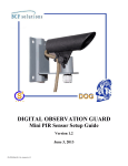
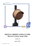
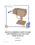
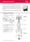
DIGITAL OBSERVATION GUARD
Duress Alarm Installation Guide
Version 1.0
June 7, 2013
Duress-Alarm-Installation-Guide-v1_manual-v1.0
Table of Contents
Function .................................................................................................................................................................................. 3
Installation .............................................................................................................................................................................. 3
Setup ....................................................................................................................................................................................... 5
Panic Module Setup ............................................................................................................................................................ 5
Duress Alarm Setup............................................................................................................................................................. 7
Software Configuration ........................................................................................................................................................... 9
Testing the Setup .................................................................................................................................................................. 10
Direct Wiring the Duress Alarm ............................................................................................................................................ 10
Table of Figures
Figure 1: Duress alarm kit ....................................................................................................................................................... 3
Figure 2: Mounting hardware ................................................................................................................................................. 3
Figure 3: Mounting with velcro .............................................................................................................................................. 4
Figure 4: Mounting with the wood screws.............................................................................................................................. 4
Figure 5: Panic button and cable ............................................................................................................................................. 5
Figure 6: Slide backshell over RJ-45 connector as far as possible ......................................................................................... 5
Figure 7: Connect the mating backshell to the RJ-45 receptacle ............................................................................................ 6
Figure 8: Connect to the remote camera module .................................................................................................................... 6
Figure 9: Duress alarm and cable ............................................................................................................................................ 7
Figure 10: RJ-45 connection for the duress alarm module ..................................................................................................... 7
Figure 11: Connect alarm inputs into the DOG VPDA alarm relay outputs........................................................................... 8
Figure 12: Plug into power outlet ........................................................................................................................................... 8
Figure 13: Select Event submenu............................................................................................................................................ 9
Figure 14: Select the Per Channel Config option.................................................................................................................... 9
Figure 15: Setting channel 8 Alarm In to N/C ...................................................................................................................... 10
1
2
Function
The S4 Tech Duress Alarm Kit seen in the figure below contains all the components necessary to run a duress
alarm through the DOG system. The kit contains a panic button module, panic button cable, duress alarm
module, duress alarm cable, and a mounting hardware bag. The panic button resides near an operator in a guard
shack, reception desk, or other protected area. When the panic button is pushed, an alarm is triggered on the duress alarm
module which contains a red strobe, siren, and reset button. The strobe and siren will engage and the alarm will stay live
until the reset button is pushed by monitoring personnel.
Figure 1: Duress alarm kit
Installation
The duress alarm kit is installed by mounting the panic button module at an operator station such as in a guard shack,
reception desk, etc. The panic button module is typically mounted on a wall or under a desk. The duress alarm module is
mounted at the monitoring station. It is typically mounted on a wall or on top of a table or desk. The hardware kit seen
below, provides wood screws for hard mounting into wood and velcro for mounting onto most surfaces. The velcro is
quite strong and will hold the modules robustly on both horizontal or vertical surfaces. The wood screws are recommend
for surfaces where the velcro may not adhere well.
Figure 2: Mounting hardware
3
To mount the modules with the velcro, simply separate the two velcro pieces. Peel off the protective film and stick on
piece onto the bottom of a duress alarm module. Do the same with the other half on the chosen mounting surface.
Figure 3: Mounting with velcro
If velcro does not work well then a woodscrew mount may be necessary. Remove the top cover of the duress alarm
module as shown below. Take a wood screw and insert it into the mounting hole right next to the screw hole for the lid.
The mounting hole goes all the way through the box and out the backside. Take a phillips head screwdriver and drive the
woodscrew into the mounting surface. Do this on all four corners or two of the diagonals.
Figure 4: Mounting with the wood screws
4
Setup
Once the panic button and duress alarm modules have been mounted, the system can be set up. The connector backshells
discussed below are simply used to provide water and dust protection and strain relief to the cable, they are not critical for
cable function.
Panic Module Setup
The panic button cable is used to connect the panic button into the sensor port of a DOG camera module.
Figure 5: Panic button and cable
Take the connector backshell and slide it up the CAT-5 cable until it goes over the back of the RJ-45 connector. Make
sure that the small plastic tab on the RJ-45 connector slides into the groove on the backshell as seen in the figure below.
Figure 6: Slide backshell over RJ-45 connector as far as possible
5
With the RJ-45 connector snugly inside the backshell, plug it into the RJ-45 receptacle on the panic button module as
seen in the picture below. Then while pushing the module in, twist it clockwise until it locks into place.
Figure 7: Connect the mating backshell to the RJ-45 receptacle
On the other end of the cable, simply plug the circular connector into the fixed camera that is nearest the panic button.
Ideally the fixed camera will be mounted so that the panic button area is under video surveillance. Line up the connector
with the sensor port on the camera module and push it in and twist clockwise until it locks into place as seen in the figure
below.
Figure 8: Connect to the remote camera module
6
Duress Alarm Setup
The duress alarm has a siren, a strobe light and a reset button that is pushed to reset the alarm. The duress alarm cable is a
triple segment cable used to connect the duress alarm into the alarm relay port of the DOG Base Station VPDA module
and to a 110-240VAC power outlet.
Figure 9: Duress alarm and cable
Slide the backshell and connect the RJ-45 end of the cable into the duress alarm module just like it was done for the panic
button module.
Figure 10: RJ-45 connection for the duress alarm module
7
On the second end of the cable take the green connector and slide it into the Alarm Relays port on the back of the DOG
Base Station VPDA module as shown in the picture below.
Figure 11: Connect alarm inputs into the DOG VPDA alarm relay outputs
On the third end of the duress alarm cable, simply plug the power connector into a wall outlet supporting 100-240VAC.
***WARNING: Do not do this until the rest of the system and software have been configured or the alarm will go off.
Figure 12: Plug into power outlet
8
Software Configuration
The system is currently configured so that the duress alarm is used on Channel 8 of any of the supplied DOG DVR units.
That means that the panic button cable should be plugged into the fixed camera that is attached to channel 8 of any one of
the DOG systems. The DOG Base Station that is chosen to host the duress alarm should be configured as follows.
From the main menu of the DOG system, select the Event icon as seen in the figure below, and hit Enter.
Figure 13: Select Event submenu
In the Event submenu, select the Per Channel Config option and shown in the figure below.
Figure 14: Select the Per Channel Config option
9
From the Per Channel Config submenu, click on the Channel Select option and hit Enter. Select CH08 (channel 8) and
hit Enter. Then click on the Alarm In option and hit Enter. Select N/C and hit Enter again. The screen should look like
the figure below. Use the ESC (Escape button) to go all the way back out of the menus. The DVR should be set.
Figure 15: Setting channel 8 Alarm In to N/C
Testing the Setup
Once the system has been set up and the software properly configured, you can run a test. Plug in the AC adapter for the
duress alarm module. This will cause an instant alarm since it energizes the relays. Simply push the reset button and the
alarm will turn off. If the alarm does not turn off then check the hardware and software configuration again.
Once the alarm is turned off, pushing the panic button will cause it to turn back on. It will stay on until the reset button is
pushed again. The video feed on channel 8 will show a small letter A each time the alarm is activated and the A should
disappear within 30 seconds of the alarm being turned off. If that is not the case then the hardware and software
configuration should be checked again.
Direct Wiring the Duress Alarm
The panic button may be connected directly to the duress alarm module by cutting the circular connector off the panic
button cable and exposing the blue and blue and white wires. Next remove the red and black alarm input wires from the
green connector by pushing the small orange buttons on the connector in with a flathead screwdriver and then pulling the
wires out as the button is held down. Now simply connect the blue and blue-white wires from the panic button cable
directly to the black and red alarm wires (the order does not matter). Note that if the distance between the panic button
and the duress alarm module is longer than the supplied cable, then an intermediate CAT-5 cable can be used to extend
the panic button CAT-5 cable.
10
Contact Info
For questions or support, please see our website at: www.bcfsolutions.net or contact: [email protected], 703-9569088.
For user manual or other technical downloads go to the customer tab on the website and login with the following: user:
customer password: 2004-S4Tech.
11