1
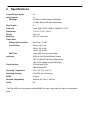
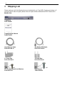
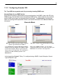
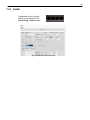
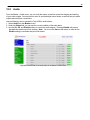
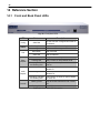
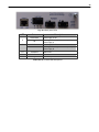
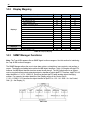
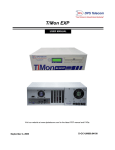
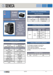
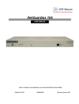
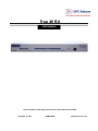
Trap 48 RA
USER MANUAL
Visit our website at www.dpstelecom.com for the latest PDF manual and FAQs.
December 16, 2013
D-UM-TRAPR
Firmware Version 1.0A
Revision History
December 16, 2013
Added play cound and parse to Edit>Audio screen
July 25, 2013
Removed HTTPS
January 21, 2013
Added relay specification option to Edit>Audio
menu
December 12, 2012
Initial release
This document contains proprietary information which is protected by copyright. All rights are reserved. No part of this
document may be photocopied without prior written consent of DPS Telecom.
All software and manuals are copyrighted by DPS Telecom. Said software and manuals may not be reproduced, copied,
transmitted or used to make a derivative work, by either mechanical, electronic or any other means in whole or in part, without
prior written consent from DPS Telecom, except as required by United States copyright laws.
© 2013 DPS Telecom
Notice
The material in this manual is for information purposes and is subject to change without notice. DPS Telecom shall not be
liable for errors contained herein or consequential damages in connection with the furnishing, performance, or use of this
manual.
Contents
Visit our w ebsite at w w w .dpstele.com for the latest PDF m anual and FAQs
1 Trap 48 RA Overview
1
2 Specifications
3
3 Shipping List
4
4 Installation
6
4.1
Tools Needed
6
4.2
Mounting
6
5 Trap 48 RA Back Panel
7
5.1
Power Connection
7
5.2
LAN Connection
8
5.3
Relay Outputs RJ-45 Connectors
8
5.4
Audio Output Connectors
6 Trap 48 RA Front Panel
6.1
RJ-45 Console Port
7 Quick Start: How to Connect to the Trap 48 RA
10
11
11
12
7.1
...via RJ-45 Console Port (using TTY Interface)
12
7.2
...via LAN (First Time Connection to a Unit at Factory Defaults)
13
8 TTY Interface
14
9 Trap 48 RA Web Browser
15
9.1
Logging on to the Trap 48 RA
9.1.1
Changing the Default Password
10 Trap 48 RA - Quick Turn Up
15
16
17
10.1
How to Configure Trap Parsers for an Output
17
10.2
Useful Tools
19
11 Edit Menu Field Descriptions
20
11.1
System
20
11.2
Ethernet
21
11.3
Controls
22
11.3.1
Configuring Granular OID
23
11.4
Audio
25
11.5
System Alarms
27
11.6
Ping Targets
28
11.7
Notifications
29
11.8
11.7.1
Notification Settings
30
11.7.2
Schedule
31
11.7.3
How to Send Email Notifications
32
Variable Bindings
35
11.9
Date and Time
36
11.10
Timers
37
11.11
Reboot
37
12 Monitoring via the Web Browser
38
12.1
Controls
38
12.2
Audio
39
12.3
Alarms
40
12.4
Ping Targets
40
13 Firmware Upgrade
41
14 Reference Section
42
14.1
Front and Back Panel LEDs
42
14.2
Display Mapping
44
14.3
SNMP Manager Functions
44
14.4
SNMP Granular Trap Packets (Outbound)
45
15 Frequently Asked Questions
47
15.1
General FAQs
47
15.2
SNMP FAQs
48
16 Technical Support
49
17 End User License Agreement
50
1
1
Trap 48 RA Overview
Fig. 1.1 The easy-to-install Trap 48 RA operates up to 48 relays and 16 audio outputs
Overview
The Trap 48 RA is a device that operates up to 48 relays and 16 audio outputs using received SNMP
trap information. The user can configure each relay to operate or release based on the enterprise,
generic-trap, and specific-trap information of a SNMP v1 trap or the trap OID of a SNMP v2c trap. Each
SNMP trap can also be defined by an optional variable binding. This telco-grade remote is housed in a
durable aluminum chassis that uses one standard rack units for mounting.
48 Relay Outputs
16 Audio Outputs
64 Ping Targets
Convenient RJ-45 connectors are used to securely terminate relay and audio outputs
On the back panel of the Trap 48 RA, the 28 RJ-45 connectors securely terminate the relay and audio
outputs. There are four relays grouped per RJ-45, and one audio per RJ-45 connector.
Visual alarm interface
The front panel LED indicators provide visual indication of relay point and audio output status. Two
outputs share one LED (ex. 1/25, 2/26 etc.). LEDs that are on indicate active outputs. LEDs that are off
indicate inactive outputs.
2
Web Browser Interface
From the device’s easy-to-use web interface, you do all of the configuration setup tasks like reversing
the relay energize state , or selecting audio message, on an individual output basis. Additionally, from
the web interface you are able to view the status of all the outputs.
3
2
Specifications
Control Relay Outputs:
48
Audio Outputs:
16
DB Range:
-25 dBm to 5 dBm Software Selectable
(-10 dBm default, 600 Ohm balance pair)
Ping Targets:
64
Protocols:
Telnet, ICMP, DCPX, SNMPv1, SNMPv2c*, HTTP
Dimensions:
1.72" H x 17" W x 7.38" D
Weight:
3 lbs 4 oz
Mounting:
19" or 23" rack mount
Power Input
Voltage Options Include:
Dual Feed +12 VDC
Current Draw:
600 mA @ 12 Vdc
300 mA @ 24 Vdc
150mA @ 48 Vdc
GMT Fuse:
Interfaces:
1 Amp GMT Fuse (recommended)
28 RJ-45 Ports for Audio/Relay Outputs
1 RJ-45 10BaseT half-duplex Ethernet port
1 RJ-45 Front-panel console RS232 port
Visual Interface:
36 Front Panel LEDs
5 Back Panel LEDs
Operating Temperature:
32° to 140° F (0° to 60° C)
Operating Humidity:
0% to 95% non-condensing
MTBF:
60 years
Windows Compatibility:
Windows XP, Vista, 7 32/64 bit
RoHS:
5/6
*The Trap 48 RA can only process inbound SNMP v2c traps; it can't send v2c traps, but can send v1
traps.
4
3
Shipping List
Please make sure all of the following items are included with your Trap 48 RA. If parts are missing, or if
you ever need to order new parts, please refer to the part numbers listed and call DPS Telecom at 1800-622-3314.
Trap 48 RA
D-PK-TRAPR
Trap 48 RA User Manual
D-UM-TRAPR
14 ft. Ethernet Cable
D-PR-923-10B-14
6 ft. RJ45 to DB9 Cable
D-PR-1051-10A-06
23" Rack Ears
D-CS-325-10A-01
19" Rack Ears
D-CS-325-10A-00
x8
3/8" Ear Screws and Lock Washers
2-000-60375-05
x4
Rack Screws
1-000-12500-06
5
x4
Alternate Rack Screws
2-820-80750-03
Pads
2-015-00030-00
x3
1 Amp GMT Fuses
2-741-01000-00
x2
Lg. Locking Power Connectors
2-820-35102-00
Keps Nut (on unit)
2-002-01421-00
x4
Zip Ties
1-012-00106-00
6
4
4.1
Installation
Tools Needed
To install the Trap 48 RA, you'll need the following tools:
Phillips No. 2 Screwdriver
Small Standard No. 2 Screwdriver
PC with terminal emulator,
such as HyperTerminal
4.2
Mounting
Fig. 4.1 The Trap 48 RA can be flush or rear-mounted
The Trap 48 RA occupies one standard rack unit. The Trap 48 RA mounts in a 19" or 23" rack, and can
be mounted on the right or left, in the flush-mount or rear mount locations, as shown in Fig. 4.1.
The rack ears can be rotated 90° for wall mounting or 180º for other mounting options.
Fig. 4.2
Fig. 4.3
7
5
Trap 48 RA Back Panel
Fig 5.1 Trap 48 RA back panel connections
5.1
Power Connection
The Trap 48 RA is powered by two screw-locking RIA power connectors.
Fig. 5.2 The Trap48 RA's power inputs
Note: Always use safe power practices when making power connections. Be sure to remove
fuses from the fuse distribution panel, as well as the back of the unit, before making your
power connections.
To connect the unit to a power supply:
1. Use the grounding lug to connect the unit to earth ground. The grounding lug is next to the symbol .
2. Insert the eyelet of the earth ground cable between the two bolts on the grounding lug (Ground cable
not included).
3. Insert a battery ground into the power connector plug's right terminal and tighten the screw.
4. Insert a battery lead to the plug's left terminal and tighten its screw.
5. Insert fuse into the fuse distribution panel.
6. Check the power status LED for polarity. (eg. Green = Good, Off = Bad)
7. Measure voltage. Connect the black cable onto the ground connector of your DVM and red cable
onto the other connector of your DVM. The voltmeter should read between +12VDC and +18VDC.
Note: The voltage range will depend on build and power input source. If you experience any issues with
powering your unit, contact DPS Telecom technical support at 559-454-1600 or [email protected]
8. Insert the local fuse into the power fuse slot. The power plug can be inserted into the power
connector only one way to ensure the correct polarity.
Note: The negative voltage terminal is on the left and the GND terminal is on the right.
9. Verify that the
LED is lit. To confirm that power is correctly connected, the front panel status LED
will flash RED and GREEN, indicating that the firmware is booting up.
8
5.2
LAN Connection
Fig. 5.3 LAN Port
To connect the Trap 48 RA to the LAN, insert a standard RJ45 Ethernet cable into the 10BaseT
Ethernet port on the back of the unit. If the LAN connection is OK, the LNK LED will illuminate SOLID.
5.3
Relay Outputs RJ-45 Connectors
Fig. 5.4 Relay Outputs
On the back panel of the Trap 48 RA, the 12 RJ-45 connectors along the top securely terminate the
relay outputs. See pinouts below:
RLY 1-4
CT 1 CO
CT 1 SW
CT 2 CO
CT 2 SW
CT 3 CO
CT 3 SW
CT 4 CO
CT 4 SW
RLY 5-8
CT 5 CO
CT 5 SW
CT 6 CO
CT 6 SW
CT 7 CO
CT 7 SW
CT 8 CO
CT 8 SW
Control Relays 1-16
Pin #
RLY 9-12
1
CT 9 CO
2
CT 9 SW
3
CT 10 CO
4
CT 10 SW
5
CT 11 CO
6
CT 11 SW
7
CT 12 CO
8
CT 12 SW
Pin # RLY 13-16
1
CT 13 CO
2
CT 13 SW
3
CT 14 CO
4
CT 14 SW
5
CT 15 CO
6
CT 15 SW
7
CT 16 CO
8
CT 16 SW
Pin #
1
2
3
4
5
6
7
8
Pin #
1
2
3
4
5
6
7
8
9
Control Relays 17-32
RLY 17-20 Pin # RLY 25-28
CT 17 CO
1
CT 25 CO
CT 17 SW
2
CT 25 SW
CT 18 CO
3
CT 26 CO
CT 18 SW
4
CT 26 SW
CT 19 CO
5
CT 27 CO
CT 19 SW
6
CT 27 SW
CT 20 CO
7
CT 28 CO
CT 20 SW
8
CT 28 SW
RLY 21-24 Pin # RLY 29-32
CT 21 CO
1
CT 29 CO
CT 21 SW
2
CT 29 SW
CT 22 CO
3
CT 30 CO
CT 22 SW
4
CT 30 SW
CT 23 CO
5
CT 31 CO
CT 23 SW
6
CT 31 SW
CT 24 CO
7
CT 32 CO
CT 24 SW
8
CT 32 SW
Pin #
1
2
3
4
5
6
7
8
Pin #
1
2
3
4
5
6
7
8
Control Relays 33-48
RLY 33-36 Pin # RLY 41-44
CT 33 CO
1
CT 41 CO
CT 33 SW
2
CT 41 SW
CT 34 CO
3
CT 42 CO
CT 34 SW
4
CT 42 SW
CT 35 CO
5
CT 43 CO
CT 35 SW
6
CT 43 SW
CT 36 CO
7
CT 44 CO
CT 36 SW
8
CT 44 SW
RLY 37-40 Pin # RLY 45-48
CT 37 CO
1
CT 45 CO
CT 37 SW
2
CT 45 SW
CT 38 CO
3
CT 46 CO
CT 38 SW
4
CT 46 SW
CT 39 CO
5
CT 47 CO
CT 39 SW
6
CT 47 SW
CT 40 CO
7
CT 48 CO
CT 40 SW
8
CT 48 SW
Pin #
1
2
3
4
5
6
7
8
Pin #
1
2
3
4
5
6
7
8
Fig 5.5 Jumpers
The build option determines if jumpers are present. If they are not, the unit will be hand wired for either
N/O if N/C on all relays. Check your product number description for your device's configuration.
10
5.4
Audio Output Connectors
Fig. 5.6 Audio Outputs
On the back panel of the Trap 48 RA, the 16 RJ-45 connectors along the bottom securely terminate the
audio outputs. See pinout below:
Note: Only pins 1 & 2 are used for the audio outputs' RJ-45 connections.
11
6
Trap 48 RA Front Panel
Fig. 6.1 Trap 48 RA front panel
6.1
RJ-45 Console Port
Use the front-panel RJ-45 console port to connect the Trap 48 RA to a PC for onsite unit configuration.
To connect via the RJ-45 console port, use the included DB9 to RJ-45 cable. Note: The console port
is RS232.
Fig 6.2 RJ-45 Pinouts (Console Port Only)
12
7
Quick Start: How to Connect to the Trap 48 RA
Most Trap 48 RA users find it easiest to give the unit an IP address, subnet and gateway through the
front serial console port (TTY interface) to start. Once these settings are saved and you reboot the unit,
you can access it over LAN to do the rest of your databasing via the Web Browser interface.
Alternative option: You can skip the TTY interface by using a LAN crossover cable directly from your
PC to the Trap 48 RA and access its Web Browser. See the "...via LAN" section of this chapter.
7.1
...via RJ-45 Console Port (using TTY Interface)
Fig. 7.1 Trap 48 RA Console Port
The simplest way to connect to the Trap 48 RA is over a physical cable connection between your PC's
COM port and the Trap 48 RA's console port.
Select the following COM port options:
• Bits per second: 9600
• Data bits: 8
• Parity: None
• Stop bits: 1
• Flow control: None
When a connection is established (sometimes accompanied by receipt of a hex byte), press Enter to
activate the configuration menu.
The default username is "admin" and the default password is "dpstelecom".
You can perform basic configuration via the console port - but if you like, you can connect via the
console port just to configure the Trap 48 RA's Private LAN IP address, and then do the rest of your
configuration via a LAN connection.
13
7.2
...via LAN (First Time Connection to a Unit at Factory Defaults)
Fig 7.2 Connection through Ethernet port
To connect to the Trap 48 RA via LAN, all you need is the unit's IP address (Default IP address
is 192.168.1.100).
If you DON'T have LAN, but DO have physical access to the Trap 48 RA, connect using a LAN
crossover cable. NOTE: Newer PCs should be able to use a standard straight-through LAN cable and
handle the crossover for you. To do this, you will temporarily change your PC's IP address and subnet
mask to match the Trap 48 RA's factory default IP settings. Follow these steps:
1. Get a LAN crossover cable and plug it directly into the Trap 48 RA's LAN port.
2. Look up your PC's current IP address and subnet mask, and write this information down.
3. Reset your PC's IP address to 192.168.1.200. Contact your IT department if you are unsure how
to do this.
4. Reset your PC's subnet mask to 255.255.0.0. You may have to reboot your PC to apply your
changes.
5. Once the IP address and subnet mask of your computer coincide with the unit, you can access
the Trap 48 RA via a Telnet session or via Web browser by using the unit's default IP address
of 192.168.1.100.
6. Provision the Trap 48 RA with the appropriate information, then change your computer's IP
address and subnet mask back to their original settings.
Now you're ready to do the rest of your configuration via LAN. Plug your Trap 48 RA into your LAN and
see the "Logging On to the Trap 48 RA" section to continue databasing using the Web Browser.
14
8
TTY Interface
The TTY interface is the Trap 48 RA's built-in interface for basic configuration. From the TTY interface,
you can:
Edit the IPA, subnet, and gateway
Set unit back to factory defaults
Debug and troubleshoot
Ping other devices on the network
Note: For more advanced configuration tools, please use the Web Browser Interface.
For Telnet, connect to the IP address at port 2002 to access the configuration menus after initial LAN/
WAN setup. Telnet sessions are established at port 2002, not the standard Telnet port as an
added security measure.
If you're using Windows 7, then you'll need to install telnet before you can use the TTY interface. To
install telnet, open up your command line (type "cmd" into the search bar in the Start Menu). Select
cmd.exe to run the command line.
From the command line, type in pkgmgr /iu:"TelnetServer" then press enter. When the command
prompt appears again, the installation is complete.
Menu Shortcut Keys
The letters before or enclosed in parentheses () are menu shortcut keys. Press the shortcut key to
access that option. Pressing the ESC key will always bring you back to the previous level. Entries are
not case sensitive.
15
9
Trap 48 RA Web Browser
The Trap 48 RA features a built-in Web Browser
Interface that allows you to manage outputs and
configure the unit through the Internet or your Intranet.
You can quickly set up descriptions, view status, issue
commands, configure notification information, and
more using most commonly used browsers.
9.1
Logging on to the Trap 48 RA
For Web Interface functionality, the unit must first be configured with some basic network addresses. If
this has not been done yet, refer to the section "Quick Start: How to Connect to the Trap 48 RA" for
instructions on initial configuration.
1. To connect to the Trap 48 RA from your Web browser, enter its IP address in the address bar of
your web browser. It may be helpful to bookmark the logon page to avoid entering this each time.
Note: The unit requires that it's accessed via HTTPS. The IP address of the unit in your address
bar should be prefaced with "https://".
2. After connecting to the unit's IP address, enter your login information and click OK. NOTE: The
factory default username is "admin" and the password is "dpstelecom".
Best Practice: DPS Telecom suggests that you change your password before configuring your
unit as seen in section 9.1.1 Changing the Default Password.
3. In the left pane, you will see the Monitor menu (blue) and Edit menu (green) The Monitor menu
links are used to view the current status of alarms. The Edit menu is used to change the unit's
configuration settings. All the software configuration will occur in the Edit menu. The following
sections provide detailed information regarding these functions.
16
9.1.1
Changing the Default Password
The password can be configured from the Edit > System screen. The minimum password length is
four characters; however, DPS recommends setting the minimum password length to at least five
characters.
Use the following steps to change the logon password:
1. From the Edit menu select System.
2. Enter the new user name in the User field.
3. Enter the new password in the Password field.
4. Click the Save button.
Fig. 9.1 - Global System Settings section of the Edit > System menu
17
10 Trap 48 RA - Quick Turn Up
The next section of this manual will walk you through one of the Trap 48 RA's most common
procedures. You will learn how to configure your inbound traps for an audio output - all using the Web
browser. For details on entering your settings into each Web browser menu, go to section 11 "Edit
Menu Field Descriptions."
10.1
How to Configure Trap Parsers for an Output
1. Click on the System button in the Edit menu and enter a valid community name for SNMP TRAP
requests in the "Inbound Trap Community" field. Be sure to Save your settings.
Fig. 10.1 - "Inbound Trap Community" under SNMP Settings in the Edit > System menu.
18
2. Next, navigate to the Edit > Audio menu.
Fig. 10.2 - The Edit > Audio menu.
3. Click on the Advanced<< tab next to your corresponding output.
Fig. 10.3 - The Advanced tab under Edit > Audio
19
4. Enter the Enterprise/OID that matches the Object Identifier of your SNMP device, and select
"enterpriseSpecific(6)" from the Generic dropdown menu.
5. If using SNMP version 1, make sure that the Specific matches the received Specific in your SNMP
device's TRAP.
6. For inputs that are not Enterprise-specific, the Specific needs to be set to 0 and another Generic
should be selected.
7. If necessary, configure a Variable Binding. For more information, see Section 10.8, Variable
Bindings. If using a variable binding, make sure Value matches the received TRAP variable binding
value.
8. Specify the Type of sound, Play Count, and Interval.
9. Scroll to either the top or bottom of the interface window, and click Save.
Note: If Stop on clear is checked, the audio output will stop when it receives the specified TRAP. This
option is left unchecked by default.
10.2
Useful Tools
iReasoning
iReasoning's MIB browser is a useful tool for managing SNMP enabled network devices and
applications. The MIB browser allows you to send, receive, and process SNMP traps according to its
rule engine. The iReasoning MIB browser runs on Windows, Mac OS X, Linux and other UNIX platforms,
and can be a valuable tool to use along with your Trap 48 RA device.
http://www.ireasoning.com/
Wireshark
Wireshark is a network protocol analyzer that lets you capture and interactively browse the traffic
running on a computer network. Used in conjunction with your Trap 48 RA, Wireshark can provides
useful visibility, allowing you to monitor and troubleshoot your network activity.
http://www.wireshark.org/
20
11 Edit Menu Field Descriptions
11.1
System
From the Edit > System menu, you will configure and edit the global system, T/Mon and control settings for the
Trap 48 RA.
Fig. 11.1 - The Edit > System menu
Global System Settings
A name for this Trap 48 RA. (Optional field)
The location of this Trap 48 RA. (Optional field)
Contact telephone number for the person responsible for this Trap 48 RA. (Optional field)
A valid email address used by the Trap 48 RA for sending email alarm notifications.
Used to change the username for logging into the unit.
Used to change the password for logging into the unit (case-sensitive).
SNMP Settings
Listening Port
Enter the port number which traps must be sent to.
Get Community
Community name for SNMP requests. (case-sensitive).
Set Community
Community name for SNMP SET requests. (case-sensitive).
Inbound Trap Community
Community name for SNMP TRAP requests. (case-sensitive).
DCP Responder Settings (For use with T/Mon Master Station)
DCP Unit ID
User-definable ID number for this Trap 48 RA (DCP Address).
Listen DCP
Choose to listen DCP over LAN. May also be disabled.
DCP LAN
Enter the DCP port for this Trap 48 RA (UDP/TCP port).
System Controls
Used to restore all factory default settings to the Trap 48 RA. Do not initialize the non-volatile
Initialize Configuration
RAM (NVRAM) unless you want to re-enter all of your configuration settings again.
Backup Configuration
Save the Trap 48 RA's configuration as a .BIN file to your local PC.
Click the "Upload" link and select a .BIN configuration file that you saved previously to your
Restore Configuration
local PC. This will restore the saved configuration.
Name
Location
Contact
"From" Email Address
User
Password
Best Practice: Always make a copy of your Trap 48 RA's configurations
21
11.2
Ethernet
The Edit > Ethernet menu allows you to define and configure Ethernet settings.
Fig. 11.2 - The Edit > Ethernet menu
MAC Address
Host Name
Enable DHCP
Unit IP
Subnet Mask
Gateway
DNS Server 1
DNS Server 2
Ethernet Settings
Hardware address of the Trap 48 RA. (Not editable - For reference only.)
Used only for local web browsing. Example: If you don't want to remember this Trap 48 RA's IP
address, you can type in a name is this field, such as Trap 48 RA. Once you save and reboot
the unit, you can now browse to it locally by simply typing in "Trap 48 RA" in the address bar (no
"https://" needed).
Used to turn on Dynamic Host Connection Protocol. NOT recommended, because the unit is
assigned an IP address from your DHCP server. The IP you've already assigned to the unit
becomes inactive. Using DHCP means the unit will NOT operate in a T/Mon environment.
IP address of the Trap 48 RA.
A road sign to the Trap 48 RA, telling it whether your packets should stay on your local network
or be forwarded somewhere else on a wide-area network.
An important parameter if you are connected to a wide-area network. It tells the Trap 48 RA
which machine is the gateway out of your local network. Set to 255.255.255.255 if not using.
Contact your network administrator for this info.
Primary IP address of the domain name server. Set to 255.255.255.255 if not using.
Secondary IP address of the domain name server. Set to 255.255.255.255 is not using.
22
11.3
Controls
A Trap 48 RA relay can be configured in the
Edit > Controls menu. You can enter your
own description for this relay and designate it
to a notification device(s)
Closeup of Relay Inputs 1-16
Fig. 11.3 - The Edit > Controls menu
Description
Notifications
Energized State
Echo Ping
Set
Clear
Variable Binding
Value
Editing Control Relays
User-definable description for the Trap 48 RA's control.
Check which notification device(s), 1 through 8, you want to send alarm notifications for
the control.
When the box in the Energize State column is not checked, the relay's normal electrical
state is De-energized. Checking this box will set the relay's normal electrical state to
Energized.
Associates the control relay with the ping target of the same ID/Number. When a ping
fails, the relay will latch. If the ping is successful, the relay will release. Note: Enabling
Echo Ping will prevent the relay from being triggered by trap OIDs.
Advanced
Enter the Enterprise/OID, Generic Type and Specific Type to operate a relay.
Enter the Enterprise/OID, Generic Type and Specific Type to release a relay.
If defined, additional OID (from equipment connected to control relay) to uniquely identify
the SNMP trap.
Value of the variable binding. Must be integer or string (when searching for a specific
string, the string must be contained within the received trap variable binding value). Note:
Using a * in this field is like a "wild card" - any value is accepted.
Note: The Advanced tab will only appear only when "Granular" Trap Processing Mode is selected in
the Edit > System menu. Refer to section 11.6.1 for further detail.
Note: If the Description is configured in the following manner:_IP:xxx.xxx.xxx.xxx (where "xxx.xxx.xxx.
xxx" is the desired IP address), the relay will only respond to traps received from the configured IP in the
description.
23
11.3.1 Configuring Granular OID
The Trap 48 RA has a granular mode for processing incoming SNMP traps.
Granular Mode (for any SNMP device):
Each Relay will operate or release based on the trap information of an SNMPv1 trap or the OID of an
SNMPv2c trap. Granular Mode can be used with any SNMP device. Other modes are only used with
specific SNMP device types to provide specialized functionality. The Advanced>> button displays
options for inputting the Enterprise/OID, Generic, and Specific information for the Set and Clear trap
commands.
Granular Mode
SNMP v1
SNMP v2c
Fig. 11.4 - Location of the OID, Generic Type and
Specific Type information for SNMP v1
Fig. 11.5 - Location of the OID information for SNMP
v2c
In your MIB Browser (freeware MIB Browser software
available for free trial) navigate to the SNMPv1 TRAPs
to obtain the Enterprise, Generic Type and Specific
Type as seen in the image above. This information is
needed for the Set and Clear properties in the
Advanced tab.
When using a SNMP v2c TRAP, you only need to
configure the TRAP OID. The location of the OID in your
MIB Browser can be seen in the image above.
In the image below Control 1 "Relay 1" is configured using a SNMP v1 trap's Enterprise, Generic
Type and Specific Type.
Fig. 11.6
24
NOTE: To use the IP filter feature for the Granular Mode, type "_IP:xxx.xxx.xxx.xxx " (where "xxx.xxx.xxx.xxx"
is the desired IP address) in the description field followed by the IP of the source SNMP trap (example:
192.168.1.1) and only traps from the specified IP address will be processed.
Energized State
The 'Energized State' checkbox for each Relay may be used to "reverse the polarity" of that relay.
When the 'Energized State' checkbox IS NOT checked, the relay will be "normally open." On
startup, the relay will be in a released state. When the specified "Set" SNMP trap is received, the
relay will latch. When the specified "Clear" SNMP trap is received, the relay will release. This is the
commonly used configuration for 'Energized State.'
When the 'Energized State' checkbox IS checked, the relay will be "normally closed." On
startup, the relay will be in a latched state. When the specified "Set" SNMP trap is received, the relay
will release. When the specified "Clear" SNMP trap is received, the relay will latch. This is not a
common configuration, but it can be very useful in certain situations.
Energized State has no effect on Notification Devices. If you configure a Notification Device to
trigger on "Set" events and associate it with a Relay, it will always trigger when the specified "Set"
SNMP trap is received. The opposite is true for "Clear" Notification Devices when "Clear" SNMP
traps are received. Even if you've reversed the latch/release operation of a Relay using Energized
State, associated Notification Devices respond to "Set" and "Clear" SNMP traps in the same way. Of
course, this distinction is irrelevant for Notification Devices configured to trigger on "Both" event
types, which trigger on both "Set" and "Clear".
25
11.4
Audio
Configuration for the 16 audio
alarms can be done from the
Provisioning > Audio window.
Closeup of Audio Inputs 1-4
Fig. 11.7 The Edit > Audio interface
26
Number
Description
Type
Play Count
Interval
Play Time
Set
Clear
Variable Binding
Value
Stop on Clear
Volume
Test
Stop
Use Trap OIDs
Use Relays
Relays
Editing Audio
Audio port number.
User-definable description for the audio alarm.
Type of audio alert: Site-Trunking: Two beeps.
Failsoft: Regular beep.
Out-of-Range: Constant tone.
The number of times the audible alert will be played. Minimum play count value is 0 and
maximum play count value is 255. If Play Count is 0, the audio will play indefinitely until a clear
condition occurs.
The amount of time (in seconds) between alerts. Minimum interval value is 1s and maximum
interval value is 60s.
Display only. The total duration of audible alert.
Advanced>>
Enter the Enterprise/OID, Generic Type and Specific Type for turning on the audio output.
Enter the Enterprise/OID, Generic Type and Specific Type for turning off the audio output .
If defined, additional OID (from equipment connected to control relay) to uniquely identify the
SNMP trap.
Value of the variable binding. Must be integer or string (when searching for a specific string, the
string must be contained within the received trap variable binding value). Note: Using a * in this
field is like a "wild card" - any value is accepted.
When checked, stops audible alert upon receiving a clear command.
Volume slider that controls the volume of the audible alert.
Conducts a test of the current settings of the Audio Alert.
Stops the test of the Audio Alert.
Configure the audio port to use SNMP traps.
Configure the audio port to use relays.
Enter the relay(s) that will trigger the audio. Ex: entering "1-5,7,9-14" would set relays 1 to 5, 7,
and 9 to 14 to all trigger audib le alert.
Note: Each time a listed relay latches, audio will play. Play Count determines the number of
times the audio will play for each time a relay latches. A play count of 0 mean the audio will
continue to repeat as long as any relay is latched.
27
11.5
System Alarms
Fig. 11.8 - The Edit > System Alarms menu
Choose the "System" tab on the "Edit > Alarms" menu to via the system alarms. These are "software"
alarms that are internally generated by the Trap 48 RA to report various events and problems (ex. "Unit
has reset" or "NTP server connection has failed").
(first column)
Description
Rpt (Report)
Notification devices
Editing System Alarms
Alarm point number
Non-editable description for this System (housekeeping) Alarm.
Check this box to choose to report this alarm.Check the box in the green bar (top) to
have all System Alarms reported. Leave unchecked to ignore.
Check which notification device(s), 1 through 8, you want to send alarm notifications
for that alarm point. Check the box in the green bar (top) to have that notification
device send a notification for all the System Alarms.
28
11.6
Ping Targets
Configuration for the 64 ping targets can be done from the Edit > Ping Targets window.
Fig. 11.9 The Edit > Ping Targets interface
ID
Description
IP Address
Notifications
Editing Ping Targets
Point number.
User-definable description for the ping target.
IP address of the device (the ping target).
Check which notification device(s), 1 through 8, you want to send alarm notifications
for that ping target.
29
11.7
Notifications
From the initial Edit > Notifications menu, you may configure any of eight different notifications for
your Trap 48 RA's alarms. Click on the number of the notification in the far left column under No. to
begin configuring notifications.
Fig. 11.10 - The Edit > Notifications menu
After clicking on a notification, you will tell the Trap 48 RA what sorts of events you'd like to see
notifications and what sort of notification to send.
1. In the drop-down box, choose whether you'd like to receive notification for alarms, clears, or both.
You may also disable the notification by selecting the appropriate option.
2. Next, choose the sort of notification you would like sent when an event occurs. You may choose:
· Send Email to have an email sent when events occur
· Send SNMP to have a trap sent when events occur
3. Click Next > to continue configuring notifications.
Fig. 11.11 - The Notification Setting menu
30
11.7.1 Notification Settings
Email Notification Fields
Fig. 11.12 - Editing Email Notification Settings
4a. Enter the appropriate information for email notifications in the fields of the Email Notification screen.
Click Next > to continue.
Email Notification
SMTP Server IP or Host
Name
Port Number
"From" E-mail Address
"To" E-mail Address
The IP address of your email server.
The port used by your email server to receive emails, usually set to 25.
Displays the email address (defined in the Edit menu > System) that the Trap 48
RA will send email from. Not editable from this screen.
The email address of the person responsible for this Trap 48 RA, who will receive
email alarm notifications.
SNMP Outbound Notification Fields
Fig. 11.13 - Editing SNMP notification settings
4b. Enter the appropriate information for SNMP Trap notifications in the fields of the SNMP Notification
screen. Click Next > to continue.
SNMP Trap Server IP
Trap Port No.
Trap Community
SNMP Notification
The SNMP trap manager's IP address.
The SNMP port (UDP port) set by the SNMP trap manager to receive traps,
usually set to 162.
Community name for SNMP TRAP requests.
31
11.7.2 Schedule
Set a schedule for when you'd like the Trap 48 RA to send the notification configured in the previous
steps. All schedule settings default to full-time notification, 24 hours a day, 7 days a week.
Fig. 11.14 - The Schedule creation screen
Days of the week
Any Time
Notification Time
Notification Scheduling
From either Schedule 1 or 2, check which days you want to receive notifications.
Select to tell the Trap 48 RA you want to receive alarm notifications at any time for the
day(s) you've selected.
Instead of "Any Time", use these fields to only send alarm notifications during certain
hours on the day(s) you've selected.
When finished, click Test to test the notification or Finish to save the notification.
32
11.7.3 How to Send Email Notifications
1. Click on the System button in the Edit menu and enter a valid email address in the "From" Email
Address field. (You may need to check with your IT department to have one created for the unit.) This is
the address that will appear in your email as the sender.
Fig. 11.15
2. Click on the Notifications button in the Edit menu. You can setup as many as 8 different
notifications. Begin the setup "wizard" by clicking on a notification number. In this example, we'll setup
Notification 1 to send emails.
Fig. 11.16
33
3. At the Notification Setting screen, use the drop-down menu to choose whether you want
notifications for alarms, clears, or both. Now, select the Send Email button and click Next.
Fig. 11.17
4. At the Email Notification screen, you'll enter your email server settings. Enter the IP address or
Host Name of your email server (If using Host Name, DNS servers must be configured under the
ethernet settings). Enter the Port Number (usually 25) and the "To" Email Address of the technician
that will receive these emails. The "From" E-mail address is set on the "Edit > System" menu, and
cannot be modified from this menu. Click Next.
Fig. 11.18
5. At the Schedule screen, you'll select the exact days and times you want to receive email
notifications. You can set two schedules per notification. For example, you may want to receive
notifications at certain times during the week, and at different hours on the weekend. Use the check
boxes to select the days of the week, and select the time from the drop down menus. Click Finish. To
try a test notification, click the Test button (See next step.)
Fig. 11.19
34
6. If you chose to test the email notification you've just setup, you will see a popup. Click OK to send a
test email notification. Confirm all your settings by checking your email to see if you've received it.
NOTE: This test only means that your notification settings are correct, but you still need to assign the
notification to an alarm point. See the next step.
Fig. 11.20
7. Now you will associate this notification to a control. You have 8 notification devices available to use.
In the image below, you might assign Notification Device 1 to Control 1. This means that you would
receive an email notification when "Relay 1" (Control 1) changes state. Remember that Notification #1 in
the Notifications menu corresponds to the first "Notifications" column of check boxes. (Notification #2 is
the second column, and so on until Notification #8)
Fig. 11.21 Associating Controls to the Notifications Table
35
11.8
Variable Bindings
Variable bindings for the Trap Relay can be added using the Edit > Variable Bindings menu. Variable
bindings are additional OIDs (supplied by the manufacturer of the product connected to the control
relay) used to uniquely identify the SNMP trap. Variable bindings are used as an additional method of
identifying SNMP traps. Up to one variable binding can be used per relay or audio output.
Fig. 11.22 - The Edit > Variable Bindings menu
Id
OID
Editing Variable Bindings
Index number of the relay for the binding.
OID of the variable binding. Note: Using a * in this field is like a "wild card" - any value is
accepted.
36
11.9
Date and Time
Fig. 11.23 - The Edit > Date and Time menu
Date
Time
Enable NTP
NTP Server Address or
Host Name
Time Zone
Enable DST
Start Day
End Day
Time Settings
Select the current month, day, and year from the drop-down menus.
Select the current hour, minutes, and time of day fro the drop-down menus.
Automatic Time Adjustment (NTP)
Check this box to enable Network Time Protocol.
Enter the NTP server's IP address or host name, then click Sync.
Example: north-america.pool.ntp.org
Select your time zone from the drop-down menu.
Adjust Clock for Daylight Savings Time (DST)
Check this box to have the Trap Relay 64 observe Daylight Savings.
Select the month, weekday, and time when Daylight Savings will begin.
Select the month, weekday, and time when Daylight Savings will end.
37
11.10 Timers
The Timers Menu allows configuration of various intervals, such as delays between pings, audible alarm
tone length, and web refresh delay. Each timer is fully explained within the Timers Menu, as shown
below:
Fig. 11.24- The Edit > Timers menu
11.11 Reboot
Click on the Reboot link from the Edit menu will reboot the Trap 48 RA after writing all changes to
NVRAM.
Fig. 11.25- The Edit > Reboot confirmation popup
38
12 Monitoring via the Web Browser
12.1
Controls
From the Monitor > Controls menu, you can manually operate and release the relay outputs. This is
useful for manually testing your relay connections and verifying that your system works.
Use the following rules to operate the Trap 48 RA's control:
1. Select Controls from the Monitor menu.
2. Under the State field, you can see the current condition of the control.
3. Use the OPR and RLS buttons to operate and release the relays. You can use these buttons to:
a. Test the relays
b. To manually force the SNMP alarm in a known state and/or synchronize it
Fig 12.1 View the state of the control relays in the Monitor > Controls menu
39
12.2
Audio
From the Monitor > Audio menu, you can verify the status, as well as control the stopping and starting,
of your audio outputs. You can use this menu to emit and adjust sound levels, as well as test your audio
outputs and verify their connections.
Use the following rules to operate the Trap 48 RA's audio alarms:
1. Select Audio from the Monitor menu.
2. Under the Status field, you can see the current condition of the audio alarm.
3. Use the On, Off, and Disable buttons to control the audio outputs. Pressing Disable will prevent
that particular audio output from working. Note: You must click Save at the bottom in order for the
Disable setting to remember beyond a unit reboot.
Fig 12.2 View the state of the audio relays in the Monitor > Audio menu
40
12.3
Alarms
System alarms are non-editable alarms that are programmed into Trap 48 RA. The "System" tab of the
Monitor > Alarms screen provides the status of the system alarms by indicating if an alarm has been
triggered. Under the State column, the status will appear in red if an alarm has been activated, or green
if it has not been activated. The status will be displayed in green when the alarm condition is not
present.
See "Display Mapping" in the Reference Section for a complete description of system alarms.
Fig 12.3 View the status of System Alarms from the Monitor > Alarms menu.
12.4
Ping Targets
The Trap 48 RA can support up to 64 ping targets. You can view each the configured ping targets by
browsing to the Monitor > Ping Targets window.
Fig 12.4 The Monitor > Ping Targets interface
41
13 Firmware Upgrade
Before upgrading the firmware, DPS Telecom suggests that you go to System Settings >> Backup
Configuration and save your configuration settings. To access the Firmware Load screen, click on
the upload link at the top right of the browser.
To be notified every time a new firmware is released for your device, login to your My DPS account and
navigate to the Notifications page. At this page check the box that corresponds to the device that you
want firmware notifications for.
Fig. 13.1 The click able link to upgrade firmware from the Edit > System menu
At the Firmware Load screen, simply browse for the firmware update you've downloaded from www.
dpstele.com and click Load.
Fig. 13.2 Browse for downloaded firmware upgrade
If you experience any difficulty updating the firmware of your device, contact DPS tech support at 559454-1600 or at [email protected] for assistance.
Note: The firmware upgrade page is only available using HTTP web browse. HTTPS is not supported.
42
14 Reference Section
14.1
Front and Back Panel LEDs
Fig. 14.1 Front panel LEDs
LED
Status
Config
Solid Red
Status
Link
Relay
Outputs
Audio
Outputs
Console
Flashing Green
Flashing Red
Solid Green
Description
The unit has been configured and needs to
be rebooted.
Trap 48 RA application running.
Boot Loader is running.
LAN connected.
Solid Red
LAN not detected.
Solid Red
Relay is active on relay labeled 1-24.
Flashing Red
Relay is active on relay labeled 25-48.
Alternating Solid Red
and Flashing Red
Relays are active on points labeled 1/25,
2/26 etc.
Solid Red
Audio outputs are active on channels
labeled 1-8.
Flashing Red
Audio outputs are active on channels
labeled 9-16.
Alternating Solid Red
and Flashing Red
Audio outputs are active on points labeled
1/9, 2/10, etc.
Flashing Green
Trap 48 RA data transmitted over console
port.
Flashing Red
Trap 48 RA data received over console port.
Table 14.1 Front Panel LED Descriptions
43
Fig. 14.2 Back panel LEDs
LED
Status
Solid Green
A
B
Off
Solid Green
Off
FA
Solid Red
LNK
Solid Green
LAN
Description
Power supply A OK.
No voltage, low voltage or incorrect polarity on
Power supply A.
Power supply B OK.
No voltage, low voltage or incorrect polarity on
Power supply B.
Blown Fuse.
LAN connected.
Flashing Yellow
LAN Activity.
Table 14.2 Back Panel LED Descriptions
44
14.2
Display Mapping
Display 1
Display 2
Display 3
14.3
Description
Default configuration
MAC address not set
IP address not set
LAN hardware error
SNMP processing error
SNMP community error
LAN TX packet drop
Notification 1 failed
Notification 2 failed
Notification 3 failed
Notification 4 failed
NTP failed
Timed Tick
Dynamic memory full
Unit Reset
Controls 1-48
Audio Alarms 1-16
Ping Targets 1-64
Table 14.3 Display Mapping
Port
99
99
99
99
99
99
99
99
99
99
99
99
99
99
99
99
99
99
Address
1
1
1
1
1
1
1
1
1
1
1
1
1
1
1
1
1
1
Point
33
35
36
37
38
39
40
41
42
43
44
49
50
52
53
1-48
49-64
1-64
SNMP Manager Functions
Note: The Trap 48 RA appears like an SNMP Agent to other managers. Use this section for interfacing
the Trap 48 RA to other managers.
The SNMP Manager allows the user to view alarm status, set date/time, issue controls, and perform a
resync. The display and tables below outline the MIB object identifiers. Table 14.3 begins with dpsRTU;
however, the MIB object identifier tree has several levels above it. The full English name is as follows:
root.iso.org.dod.internet.private.enterprises.dps-Inc.dpsAlarmControl.dpsRTU. Therefore, dpsRTU's full
object identifier is 1.3.6.1.4.1.2682.1.4. Each level beyond dpsRTU adds another object identifying
number. For example, the object identifier of the Display portion of the Control Grid is
1.3.6.1.4.1.2682.1.4.3.3 because the object identifier of dpsRTU is 1.3.6.1.4.1.2682.1.4 + the Control
Grid (.3) + the Display (.3).
Table 14.4
45
Tbl. B1 (O.)_OV_Traps points
Tbl. B2 (.1) Identity points
Tbl. B3 (.2) DisplayGrid points
_OV_vTraps
(1.3.6.1.4.1.2682.1.4.0)
Ident
(1.3.6.1.4.1.2682.1.4.1)
DisplayEntry
(1.3.6.1.4.1.2682.1.4.2.1)
PointSet (.20)
Manufacturer (.1)
Port (.1)
PointClr (.21)
Model (.2)
Address (.2)
SumPSet (.101)
Firmware Version (.3)
Display (.3)
SumPClr (.102)
DateTime (.4)
DispDesc (.4)*
ComFailed (.103)
ResyncReq (.5)*
PntMap (.5)*
ComRestored (.014)
P0001Set (.10001) through
P0064Set (.10064)
* Must be set to "1" to perform the resync
request which will resend TRAPs for any
standing alarm.
P0001Clr (.20001) through
P0064Clr (.20064)
Tbl. B3 (.3) ControlGrid
points
Tbl. B5 (.5) AlarmEntry points
AlarmEntry
(1.3.6.4.1.2682.1.4.5.1)
ControlGrid
(1.3.6.1.4.1.2682.1.4.3)
Aport (.1)
Port (.1)
AAddress (.2)
Address (.2)
ADisplay (.3)
Display (.3)
APoint (.4)
Point (.4)
APntDesc (.5)*
Action (.5)
AState (.6)
* For specific alarm points, see
Table B6
Table 14.5
The Trap Relay 64 OID has changed from 1.3.6.1.4.1.2682.1.2 to 1.3.6.1.4.1.2682.1.4 Updated MIB files
are available on the Resource CD or upon request.
14.4
SNMP Granular Trap Packets (Outbound)
Tables 14.5 and 14.6 provide a list of the information contained in the SNMP Trap packets sent by the
Trap 48 RA.
SNMP Trap managers can use one of two methods to get alarm information:
1.Granular traps (not necessary to define point descriptions for the Trap 48 RA) OR
2.The SNMP manager reads the description from the Trap.
UDP Header
1238
162
303
0xBAB0
Description
Source port
Destination port
Length
Checksum
Table 14.6 UDP Headers and descriptions
46
SNMP Header
Description
0
Version
Public
Request
Trap
Request
1.3.6.1.4.1.2682.1.4
Enterprise
126.10.230.181
Agent address
Enterprise Specific
Generic Trap
8001
Specific Trap
617077
Time stamp
1.3.7.1.2.1.1.1.0
Object
NetGuardian v1.0K
Value
1.3.6.1.2.1.1.6.0
Object
1-800-622-3314
Value
1.3.6.1.4.1.2682.1.4.4.1.0
Object
01-02-1995 05:08:27.760
Value
1.3.6.1.4.1.2682.1.4.5.1.1.99.1.1.1
Object
99
Value
1.3.6.1.4.1.2682.1.4.5.1.2.99.1.1.1
Object
1
Value
1.3.6.1.4.1.2682.1.4.5.1.3.99.1.1.1
Object
1
Value
1.3.6.1.4.1.2682.1.4.5.1.4.99.1.1.1
Object
1
Value
1.3.6.1.4.1.2682.1.4.5.1.5.99.1.1.1
Object
Rectifier Failure
Value
1.3.6.1.4.1.2682.1.4.5.1.6.99.1.1.1
Object
Alarm
Value
Table 14.7 SNMP Headers and descriptions
47
15 Frequently Asked Questions
Here are answers to some common questions from Trap 48 RA users. The latest FAQs can be found
on the Trap 48 RA support web page, http://www.dpstele.com.
If you have a question about the Trap 48 RA, please call us at (559) 454-1600 or e-mail us at
[email protected]
15.1
General FAQs
Q. How do I telnet to the Trap 48 RA?
A. You must use Port 2002 to connect to the Trap 48 RA. Configure your Telnet client to connect using
TCP/IP (not "Telnet," or any other port options). For connection information, enter the IP address of
the Trap 48 RA and Port 2002. For example, to connect to the Trap 48 RA using the standard
Windows Telnet client, click Start, click Run, and type "telnet <Trap 48 RA IP address> 2002."
Q. How do I connect my Trap 48 RA to the LAN?
A. To connect your Trap 48 RA to your LAN, you need to configure the unit IP address, the subnet
mask and the default gateway. A sample configuration could look like this:
Unit Address: 192.168.1.100
subnet mask: 255.255.255.0
Default Gateway: 192.168.1.1
Save your changes by writing to NVRAM and reboot. Any change to the unit's IP configuration
requires a reboot.
Q. When I connect to the Trap 48 RA through the craft port on the front panel it either doesn't
work right or it doesn't work at all. What's going on?
A. Make sure your using the right COM port settings. Your COM port settings should read:
Bits per second: 9600 (9600 baud)
Data bits: 8
Parity: None
Stop bits: 1
Flow control: None
Important! Flow control must be set to none. Flow control normally defaults to hardware in most
terminal programs, and this will not work correctly with the Trap 48 RA.
Q. The LAN link LED is green on my Trap 48 RA, but I can't poll it from my T/Mon.
A. Some routers will not forward packets to an IP address until the MAC address of the destination
device has been registered on the router's Address Resolution Protocol (ARP) table. Enter the IP
address of your gateway and your T/Mon system to the ARP table.
Q. I'm unsure if the voltage of my power supply is within the specified range. How do I test the
voltage?
A. Connect the black common lead of a voltmeter to the ground terminal of the battery. Connect the
red lead of the voltmeter to the batter's VCD terminal. The voltmeter should read between +12
and +24VDC for +12VDC build.
48
15.2
SNMP FAQs
Q. Which version of SNMP is supported by the SNMP agent on the Trap 48 RA?
A. SNMP v1 and SNMPv2c.
Q. How do I configure the Trap 48 RA to send traps to an SNMP manager? Is there a separate
MIB for the Trap 48 RA? How many SNMP managers can the agent send traps to? And how
do I set the IP address of the SNMP manager and the community string to be used when
sending traps?
A. The Trap 48 RA begins sending traps as soon as the SNMP managers are defined. The Trap 48 RA
MIB is included on the Trap 48 RA Resource CD. The MIB should be compiled on your SNMP
manager. (Note: MIB versions may change in the future.) The unit supports 2 SNMP managers,
which are configured by entering its IP address in the Trap Address field of Ethernet Port Setup. To
configure the community strings, choose SNMP from the Edit menu, and enter appropriate values in
the Get, Set, and Trap fields.
Q. Does the Trap 48 RA support MIB-2 and/or any other standard MIBs?
A. The Trap 48 RA supports the bulk of MIB-2.
Q. Does the Trap 48 RA SNMP agent support both Trap 48 RA and T/MonXM variables?
A. The Trap 48 RA SNMP agent manages an embedded MIB that supports only the Trap 48 RA's RTU
variables. The T/MonXM variables are included in the distributed MIB only to provide SNMP
managers with a single MIB for all DPS Telecom products.
Q. How many traps are triggered when a single point is set or cleared? The MIB defines traps
like "major alarm set/cleared," "RTU point set," and a lot of granular traps, which could
imply that more than one trap is sent when a change of state occurs on one point.
A. Generally, a single change of state generates a single trap.
Q. What does "point map" mean?
A. A point map is a single MIB leaf that presents the current status of a 64-alarm-point display in an
ASCII-readable form, where a "." represents a clear and an "x" represents an alarm.
Q. The Trap 48 RA manual talks about control relay outputs. How do I control these from my
SNMP manager?
A. The control relays are operated by issuing the appropriate set commands, which are contained in
the DPS Telecom MIB.
Q. How can I associate descriptive information with a point for the RTU granular traps?
A. The Trap 48 RA control point descriptions are individually defined using the Web Browser.
Q. My SNMP traps aren't getting through. What should I try?
A. Try these three steps:
1. Make sure that the Trap Address (IP address of the SNMP manager) is defined. (If you changed
the Trap Address, make sure you saved the change to NVRAM and rebooted.)
2. Make sure all alarm points are configured to send SNMP traps.
3. Make sure the Trap 48 RA and the SNMP manager are both on the network. Use the unit's ping
command to ping the SNMP manager.
49
16 Technical Support
DPS Telecom products are backed by our courteous, friendly Technical Support representatives, who
will give you the best in fast and accurate customer service. To help us help you better, please take the
following steps before calling Technical Support:
1. Check the DPS Telecom website.
You will find answers to many common questions on the DPS Telecom website, at http://www.
dpstele.com/support/. Look here first for a fast solution to your problem.
2. Prepare relevant information.
Having important information about your DPS Telecom product in hand when you call will greatly
reduce the time it takes to answer your questions. If you do not have all of the information when you
call, our Technical Support representatives can assist you in gathering it. Please write the information
down for easy access. Please have your user manual and hardware serial number ready.
3. Have access to troubled equipment.
Please be at or near your equipment when you call DPS Telecom Technical Support. This will help us
solve your problem more efficiently.
4. Call during Customer Support hours.
Customer support hours are Monday through Friday, from 7 A.M. to 6 P.M., Pacific time. The DPS
Telecom Technical Support phone number is (559) 454-1600.
Emergency Assistance: Emergency assistance is available 24 hours a day, 7 days a week. For
emergency assistance after hours, allow the phone to ring until it is answered with a paging message.
You will be asked to enter your phone number. An on-call technical support representative will return
your call as soon as possible.
50
17 End User License Agreement
All Software and firmware used in, for, or in connection with the Product, parts, subsystems, or derivatives thereof,
in whatever form, including, without limitation, source code, object code and microcode, including any computer
programs and any documentation relating to or describing such Software is furnished to the End User only under a
non-exclusive perpetual license solely for End User's use with the Product.
The Software may not be copied or modified, in whole or in part, for any purpose whatsoever. The Software may not
be reverse engineered, compiled, or disassembled. No title to or ownership of the Software or any of its parts is
transferred to the End User. Title to all patents, copyrights, trade secrets, and any other applicable rights shall
remain with the DPS Telecom.
DPS Telecom's warranty and limitation on its liability for the Software is as described in the warranty information
provided to End User in the Product Manual.
End User shall indemnify DPS Telecom and hold it harmless for and against any and all claims, damages, losses,
costs, expenses, obligations, liabilities, fees and costs and all amounts paid in settlement of any claim, action or
suit which may be asserted against DPS Telecom which arise out of or are related to the non-fulfillment of any
covenant or obligation of End User in connection with this Agreement.
This Agreement shall be construed and enforced in accordance with the laws of the State of California, without
regard to choice of law principles and excluding the provisions of the UN Convention on Contracts for the
International Sale of Goods. Any dispute arising out of the Agreement shall be commenced and maintained only in
Fresno County, California. In the event suit is brought or an attorney is retained by any party to this Agreement to
seek interpretation or construction of any term or provision of this Agreement, to enforce the terms of this
Agreement, to collect any money due, or to obtain any money damages or equitable relief for breach, the prevailing
party shall be entitled to recover, in addition to any other available remedy, reimbursement for reasonable attorneys'
fees, court costs, costs of investigation, and other related expenses.
51
NOTES
Warranty
DPS Telecom warrants, to the original purchaser only, that its products a) substantially conform to DPS' published
specifications and b) are substantially free from defects in material and workmanship. This warranty expires two
years from the date of product delivery with respect to hardware and ninety days from the date of product delivery
with respect to software. If the purchaser discovers within these periods a failure of the product to substantially
conform to the specifications or that the product is not substantially free from defects in material and workmanship,
the purchaser must promply notify DPS. Within reasonable time after notification, DPS will endeavor to correct any
substantial non-conformance with the specifications or substantial defects in material and workmanship, with new or
used replacement parts. All warranty service will be performed at the company's office in Fresno, California, at no
charge to the purchaser, other than the cost of shipping to and from DPS, which shall be the responsiblity of the
purchaser. If DPS is unable to repair the product to conform to the warranty, DPS will provide at its option one of the
following: a replacement product or a refund of the purchase price for the non-conforming product. These remedies
are the purchaser's only remedies for breach of warranty. Prior to initial use the purchaser shall have determined the
suitability of the product for its intended use. DPS does not warrant a) any product, components or parts not
manufactured by DPS, b) defects caused by the purchaser's failure to provide a suitable installation environment for
the product, c) damage caused by use of the product for purposes other than those for which it was designed, d)
damage caused by disasters such as fire, flood, wind or lightning unless and to the extent that the product
specification provides for resistance to a defined disaster, e) damage caused by unauthorized attachments or
modifications, f) damage during shipment from the purchaser to DPS, or g) any abuse or misuse by the purchaser.
THE FOREGOING WARRANTIES ARE IN LIEU OF ALL OTHER WARRANTIES, EXPRESS OR IMPLIED,
INCLUDING BUT NOT LIMITED TO THE IMPLIED WARRANTIES OF MERCHANTABILITY AND FITNESS FOR A
PARTICULAR PURPOSE.
In no event will DPS be liable for any special, incidental, or consequential damages based on breach of warranty,
breach of contract, negligence, strict tort, or any other legal theory. Damages that DPS will not be responsible for
include but are not limited to, loss of profits; loss of savings or revenue; loss of use of the product or any associated
equipment; cost of capital; cost of any substitute equipment, facilities or services; downtime; claims of third parties
including customers; and injury to property.
The purchaser shall fill out the requested information on the Product Warranty Card and mail the card to DPS. This
card provides information that helps DPS make product improvements and develop new products.
For an additional fee DPS may, at its option, make available by written agreement only an extended warranty
providing an additional period of time for the applicability of the standard warranty.
Technical Support
If a purchaser believes that a product is not operating in substantial conformance with DPS' published specifications or there
appear to be defects in material and workmanship, the purchaser should contact our technical support representatives. If the
problem cannot be corrected over the telephone and the product and problem are covered by the warranty, the technical
support representative will authorize the return of the product for service and provide shipping information. If the product is
out of warranty, repair charges will be quoted. All non-warranty repairs receive a 90-day warranty.
Free Tech Support is Only a Click Away
Need help with your alarm monitoring? DPS Information Services are ready to
serve you … in your email or over the Web!
www.DpsTele.com
Free Tech Support in Your Email: The Protocol Alarm Monitoring Ezine
The Protocol Alarm Monitoring Ezine is your free email
tech support alert, delivered directly to your in-box
every two weeks. Every issue has news you can use
right away:
•
Expert tips on using your alarm monitoring
equipment - advanced techniques that will save
you hours of work
•
Educational White Papers deliver fast informal
tutorials on SNMP, ASCII processing, TL1 and
other alarm monitoring technologies
•
New product and upgrade announcements keep
you up to date with the latest technology
•
Exclusive access to special offers for DPS
Telecom Factory Training, product upgrade offers
and discounts
To get your free subscription to
The Protocol register online at
www.TheProtocol.com/register
Free Tech Support on the Web: MyDPS
MyDPS is your personalized, members-only online resource.
Registering for MyDPS is fast, free, and gives you exclusive
access to:
•
•
•
•
Firmware and software downloads and upgrades
Product manuals
Product datasheets
Exclusive user forms
Register for MyDPS online at
www.DpsTele.com/register
(800) 622-3314 • www.DpsTelecom.com • 4955 E. Yale Avenue, Fresno, California 93727