1
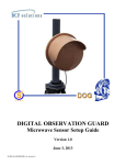
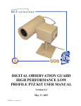
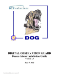
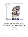
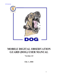
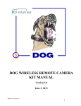
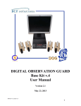
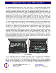
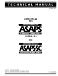
DIGITAL OBSERVATION GUARD
WIRELESS KIT MANUAL
Version 1.3
Nov. 1, 2012
DW-Kit-v2_manual-v-1.3
0
Table of Contents
Wireless Kit Description............................................................................................................................... 2
Wireless Basic Operation ............................................................................................................................. 3
Power Options .......................................................................................................................................... 4
Scrambling ................................................................................................................................................ 4
Channels ................................................................................................................................................... 4
Setting Up a Remote Monitoring Site .......................................................................................................... 5
Remote Camera Module ........................................................................................................................... 5
Setting up the Remote Hub ....................................................................................................................... 6
Connect the CAT-5 Cables ................................................................................................................... 6
Powering the Remote Wireless Hub ..................................................................................................... 7
Local AC Power ............................................................................................................................... 7
Rechargeable Commercial Battery Pack .......................................................................................... 8
Recharging the Commercial Battery Packs ...................................................................................... 9
Military Battery Pack ...................................................................................................................... 10
Setting up the Remote Transmitter Module............................................................................................ 10
Setting up the Receiver at the Base Station ................................................................................................ 13
Troubleshooting .......................................................................................................................................... 15
Table of Figures
Figure 1: DOG Wireless Kit Decal ............................................................................................................... 2
Figure 2: Wireless Kit with Optional Military Grade Case .......................................................................... 2
Figure 3: Wireless Kit System Diagram ....................................................................................................... 3
Figure 4: Power Options for the Remote Wireless Hub ............................................................................... 4
Figure 5: A Matched Remote Transmitter Module/Receiver Module Pair .................................................. 5
Figure 6: Mounted Remote Camera Module ................................................................................................ 6
Figure 7: Connecting the CAT-5 Cables to the Remote Wireless Hub ........................................................ 7
Figure 8: Using 36VDC Power Supply with Local AC Power .................................................................... 8
Figure 9: Installing the Commercial Battery Pack ....................................................................................... 8
Figure 11: Recharging the Commercial Battery Pack ................................................................................ 10
Figure 12: Installing the Military Battery ................................................................................................... 10
Figure 14: Remove the Remote Transmitter Module and Mounting Hardware ......................................... 11
Figure 15: Attach Mounting Feet to the Remote Transmitter Module ....................................................... 11
Figure 16: Connect CAT-5 Cable to the Remote Transmitter Module ...................................................... 12
Figure 17: Using Wire Ties to Mount the Remote Transmitter Module .................................................... 12
Figure 18: Pole Mounted Remote Transmitter Module.............................................................................. 13
Figure 19: Pole Mounted Receiver Module Connected the DOG Base Station ......................................... 14
Figure 20: Connecting the Receiver Module to the DOG Base Station VPD ............................................ 14
DW-Kit-v2_manual-v-1.3
1
Wireless Kit Description
The DOG Wireless kit is an accessory kit for use with the DOG Base Kit. Each Wireless kit consists of
two wireless links and associated hardware. The wireless links provide a point to point video connection
between a remote camera and the DOG Base Station. The wireless links are used to extend the range of a
remote DOG camera module or to provide coverage over problematic areas such as waterways, roads, or
other terrain in which it is difficult to run wire over. Each case can be identified by a decal just above
the handle as shown in Figure 1.
Figure 1: DOG Wireless Kit Decal
Each DOG Wireless case contains 2 wireless links with associated accessories. Two sets of commercial
battery packs are included along with two battery chargers. This allows one set of battery packs to be
recharged while the other set is deployed. Cables and mounting hardware are also included. An example
of a cased Wireless set and associated hardware is shown below.
Figure 2: Wireless Kit with Optional Military Grade Case
DW-Kit-v2_manual-v-1.3
2
Wireless Basic Operation
Each wireless link consists of a Remote Wireless Hub, a Remote Transmitter Module, a Remote Camera
Module (DOG Base Kit), and a Receiver Module. As seen in the figure below, the Remote Transmitter
Module and the Remote Camera Module can each be placed up to 1000ft away from the Remote Wireless
Hub. The Remote Wireless Hub provides power to both the Remote Camera Module and the Remote
Transmitter Module and also routes the video signal from the Remote Camera Module to the Remote
Transmitter Module.
Viewing and
Control Station
Location
100-240VAC
Power Supply
Video/Power/Data
Distribution
100-240VAC
Power Supply
CAT5 Cable Video/Power/Data to 1500 ft
Transmitter
Receiver
Scrambled Wireless Signal
Remote
Wireless
Hub
CAT-5 up to 1000ft
Figure 3: Wireless Kit System Diagram
The Receiver Module can be located up to 200 yards away from the Remote Transmitter Module and the
two modules should be facing each other to get the best signal. If the modules are not facing each other
the signal may be too weak to receive. The Receiver Module can be located up to 1500ft from the DOG
Base Station, and is connected to the CAT-5 infrastructure in the same way as a Remote Camera Module.
The Receiver Module should be installed so that it is facing the location of the Remote Transmitter
Module. There are four wireless channels centered around 1.2GHz. Each Remote Transmitter Module
and Receiver Module pair in a DOG Wireless Kit, is matched to a channel. The matched Remote
Transmitter Module and Receiver Module should always be used together.
DW-Kit-v2_manual-v-1.3
3
At the remote location, the Remote Camera Module and Remote Transmitter Module are each connected
to the Remote Wireless Hub with up to 1000ft of standard CAT-5 cable. The Remote Transmitter is then
located and mounted in a location where it has a clear line of sight to and is directly facing the Receiver
Module. The Remote Wireless Hub is then powered either from a local AC supply through its power
input jack or via an installed battery. At this point the system can be tested and an operator at the DOG
Base Station can verify that an image is being received from the camera. Once image validation has
occurred, the Remote Camera Unit is mounted in its desired location.
Power Options
The Remote Wireless Hub can supply power via its internal battery (supplied commercial battery pack or
military BA5590 battery) or though a local AC source using a power supply plugged into its jack. The
figure below shows the various power options of the Remote Wireless Hub. The Remote Wireless kit
provides a commercial battery pack, a battery recharger, and a spare battery pack for each Remote
Wireless Hub. The Remote Wireless Hub will provide approximately 14 hours of operation with either
the supplied battery pack or the BA5590 military battery.
Figure 4: Power Options for the Remote Wireless Hub
Scrambling
The video signal is scrambled by the Remote Transmitter Module so that only the Receiver Modules from
the DOG Wireless Kit can properly descramble the signal. Scrambling is performed on the analog video
signal and obscures the image to a non compliant receiver. A numerical scrambling algorithm ensures
that the scrambled image is highly obscured and very difficult to interpret or decipher.
Channels
There are four channels used by the DOG Wireless Kits. Each kit uses two channels which are assigned
to the two wireless links respectively. Each wireless link contains a matched Remote Transmitter Module
and Receiver Module which are on the same channel. As seen in the figure below, each Remote
Transmitter Module is marked with a “TX”, a serial number corresponding to the DOG Wireless Kit it
came from, and a channel sticker. Each Receiver Module is marked with an “RX”, a serial number
corresponding to the DOG Wireless Kit it came from, and a channel sticker. A Remote Transmitter
Module and Receiver Module used in a wireless link should each have the same channel sticker and serial
number as seen below.
DW-Kit-v2_manual-v-1.3
4
Figure 5: A Matched Remote Transmitter Module/Receiver Module Pair
****WARNING - THE TRANSMITTER AND RECEIVER MODULES ARE NOT TO BE MIXED WITH
THOSE FROM THE OTHER WIRELESS LINK WITHIN THE KIT OR WITH MODULES FROM OTHER
DOG KITS. IF THE MODULES ARE MIXED PERFORMANCE DEGRADATION MAY OCCUR.****
Setting Up a Remote Monitoring Site
****WARNING – RF SIGNALS CAN BE REMOTELY SENSED AND LOCATED IN THE FIELD. THE
USER IS CAUTIONED THAT USE OF A WIRELESS LINK PRODUCES A RADIO SIGNATURE.****
****WARNING – VIDEO SCRAMBLING OBSCURES THE IMAGE, BUT IN SOME CASES PARTS OF
THE IMAGE MAY STILL BE INTELLIGIBLE.****
The first step in setting a remote monitoring site is to locate the various modules. The Remote Camera
Module is located such that the camera is appropriately positioned to monitor the area of interest. The
next step is to find a location for the Remote Wireless Hub. The hub can be located up to 1000ft away
from the Remote Camera Module and if possible should be located somewhere that is protected from the
environment. Though the Remote Wireless Hub is environmentally resistant, avoiding direct sun
exposure, high temperatures, and prolonged exposure to water will ensure longer battery life and longer
operational life in general. The Remote Transmitter Module is then located within 1000ft of the Remote
Wireless Hub and must be located in a place that has a clear line of site to where the Receiver Module
will be. Ideally both the transmitter and receiver locations will be on poles, rooftops, or other points high
above the ground in order to get increased transmission range. Once the various units have been located,
CAT-5 spools can be used to run and cut cables of the appropriate length between the Remote Camera
Module and the Remote Wireless Hub, and between the Remote Wireless Hub and the Remote
Transmitter Module.
Remote Camera Module
DW-Kit-v2_manual-v-1.3
5
Installation of the DOG Remote Camera Modules is discussed in further detail in the DOG Base Kit User
Manual. The figure below shows an installed DOG Remote Camera Module. The camera is located to
point at the area of interest, and one end of a CAT-5 cable has been installed.
Figure 6: Mounted Remote Camera Module
Setting up the Remote Hub
Setting up the Remote Wireless Hub involves connecting the CAT-5 cables from the Remote Camera
Module and the Remote Transmitter Module and then installing the appropriate power option. CAT-5
cables can be measured out from a spool and constructed on the spot, or they can be measured and
fabricated beforehand.
Connect the CAT-5 Cables
To connect the CAT-5 cables to the Remote Wireless Hub, follow the steps as seen in the figure below.
First remove the weather-tight RJ-45 connector by unscrewing the nut closest to the main connector body
– a wrench may be needed. When the outer shell of the connector comes apart, loosen the large nut on
the bottom as far as possible to expand the hole so that the CAT-5 cable can be pushed through. When the
hole in the outer shell is fully expanded, push the CAT-5 cable end through (RJ-45 connector first). Once
the connector is through, run the cable through the Remote Wireless Hub. If the CAT-5 cable is being
run from the Wireless Radio to the Remote Wireless Hub then the cable needs to be plugged into the RJ45 receptacle labeled “To Radio”. If the CAT-5 cable is being run from camera to the Remote Wireless
Hub then the cable needs to be plugged into the RJ-45 receptacle labeled “To Camera”. When the RJ-45
tab clicks into place, slide the outer shell of the connector up to the main body and screw it back in till it
is tight. Then screw the lower nut down so that the CAT-5 cable is held in place by the connector. If the
CAT-5 cable does not seal well even when the connector is fully tightened, wrap some electrical tape
around the appropriate area on the CAT-5 cable a couple times to thicken it up and retry the seal.
DW-Kit-v2_manual-v-1.3
6
Figure 7: Connecting the CAT-5 Cables to the Remote Wireless Hub
****WARNING – TO PREVENT DAMAGE TO THE RJ-45 CONNECTOR WHEN REMOVING THE
CAT-5 CABLE FROM THE REMOTE WIRELESS HUB, USE A SMALL SCREWDRIVER OR
TOOL TO LIFT THE TAB ON THE RJ-45 CONNECTOR BEFORE PULLING IT OUT.****
Powering the Remote Wireless Hub
The Remote Wireless Hub utilizes 24 or 36VDC as its input voltage. This may be provided by using a
local power source with the supplied universal 36VDC power supply, or by installing either the supplied
rechargeable commercial battery pack or a military BA5590 battery.
Local AC Power
If local 110/220 VAC power is available it is recommended, since this will eliminate the need to rotate
batteries as they become discharged. Simply use the universal power supply supplied with the DOG kit to
connect to the local AC source and run the plug into the battery box through one of the cable glands.
Plug the universal power supply output into the input power jack of the Remote Wireless Hub as seen in
the picture below. Flip the battery switch to “OFF” and remember to sufficiently tighten the cable gland
once the universal power supply has been connected to the Remote Wireless Hub.
DW-Kit-v2_manual-v-1.3
7
Figure 8: Using 36VDC Power Supply with Local AC Power
Rechargeable Commercial Battery Pack
If there is no local power available at the remote monitoring site, then a battery must be used to supply
the power. The figure below shows the installation of the rechargeable commercial battery pack supplied
in the DOG Wireless Kit. If there is a discharged battery already installed, remove the battery by
disconnecting the power cable, grabbing the edges, and pulling the battery out with a slight rocking
motion.
Figure 9: Installing the Commercial Battery Pack
DW-Kit-v2_manual-v-1.3
8
The charged battery pack is then pushed into the center of the foam cutout with the terminal side of the
battery pack facing away from the circuit board on the edge of the Remote Wireless Hub. Once the
battery pack is in place, grab the battery terminal wire and the proper power cable from the circuit board
at the edge of the Remote Wireless Hub. With the two connectors side by side line them up so that the
connector pins match up and push the connectors together. Tuck the wires along the side of the battery so
there is no interference with the lid and then close the Remote Wireless Hub.
Recharging the Commercial Battery Packs
The 24VDC commercial battery packs supplied in the DOG Wireless Kit are rechargeable. When fully
charged, they will provide approximately 14 hours of power to the camera and transmitter. The universal
battery charger units supplied in the DOG Wireless Kit are used to recharge the commercial battery packs
from a 110/220 VAC 50/50Hz local AC source.
Recharging a commercial battery involves connecting it to a universal battery charger as seen in the
figure below. The current switch on the battery charger should be set to 1.0A. Place the black thermal
probe wire underneath the battery as shown, then connect the battery to the charger. When the battery is
charging the charger light will be red, and when it is fully charged the light will turn green. Please allow
4-6 hours to fully charge one of the supplied commercial battery packs.
***WARNING – CHARGING THE BATTERIES AT 1.5A MAY CAUSE OVERHEATING OF THE
BATTERY
DW-Kit-v2_manual-v-1.3
9
Figure 10: Recharging the Commercial Battery Pack
Military Battery Pack
The Remote Wireless Hub will operate with a BA5590 military battery. The figures below show the
installation of a BA5590 military battery. If there is a discharged battery already installed, remove the
battery by disconnecting the power cable, grabbing the edges, and pulling the battery out with a slight
rocking motion.
Figure 11: Installing the Military Battery
With the BA5590 battery in one hand, grab the proper power cable from the circuit board at the edge of
the Remote Wireless Hub. Line the connector up with the battery terminal and push the connector in
snugly. Then push the connected battery into the center of the foam cutout with the terminal side of the
battery facing away from the circuit board on the edge of the Remote Wireless Hub. Tuck the wires along
the side of the battery so there is no interference with the lid and then close the Remote Wireless Hub.
Setting up the Remote Transmitter Module
Once a location for the Remote Transmitter Module has been determined and the CAT-5 cable put into
place, the Remote Transmitter Module is ready to be set up and mounted. Remove a Remote Transmitter
Module from the DOG Wireless Kit, and keep track of the channel number and location so that the proper
Receiver Module will be installed afterwards. Also remove two of the mounting feet and a bag of
mounting screws as shown in the figure below.
DW-Kit-v2_manual-v-1.3
10
Figure 12: Remove the Remote Transmitter Module and Mounting Hardware
Place a mounting foot onto the top middle mounting pad of the Remote Transmitter Module as seen in the
figure below. Push the mounting foot onto the mounting pad to a snug fit. Then use a flathead
screwdriver to screw the mounting foot into the mounting pad using one of the supplied flat head screws.
Repeat with the second mounting foot on the bottom middle mounting pad of the module.
Figure 13: Attach Mounting Feet to the Remote Transmitter Module
****WARNING -ON FIRST TIME MOUNTINGS, A LARGE FORCE MAY BE NEEDED TO TIGHTEN
THE SCREWS SO A LARGE SCREWDRIVER HEAD AND POWER SCREWDRIVER ARE
RECOMMENDED ****
Once the mounting feet have been connected to the Remote Transmitter Module, the CAT-5 cable is
connected. The CAT-5 cable installation was discussed in the section on setting up the Remote Wireless
Hub. The figure below shows the process applied to the Remote Transmitter Module.
DW-Kit-v2_manual-v-1.3
11
Figure 14: Connect CAT-5 Cable to the Remote Transmitter Module
Once the mounting feet and CAT-5 cable have been installed, the Remote Transmitter Module is ready to
be mounted. The ideal location is a tall pole with a direct line of sight to the predetermined Receiver
Module location. If a pole is not available, a rooftop or other high location is recommended.
****WARNING – THE REMOTE TRANSMITTER MODULE MUST BE MOUNTED VERTICALLY
WITH THE WEATHER-TIGHT CAT-5 CONNECTOR FACING DOWN TO ENSURE PROPER
OPERATION WITH THE RECEIVER MODULE.****
As seen in the figure below, push a wire or wire tie through one mounting foot a, wrap it around the pole,
and tighten it down. Repeat for the second mounting foot, but go in the opposite direction to keep the
module centered.
Figure 15: Using Wire Ties to Mount the Remote Transmitter Module
The completed pole mounting can be seen in the figure below. Once both wire ties are tightened down,
make sure that the Remote Transmitter Module is stable and does not easily slide on the pole by
tapping/pushing on it to simulate wind loads.
DW-Kit-v2_manual-v-1.3
12
Figure 16: Pole Mounted Remote Transmitter Module
Once the Remote Camera Module, Remote Wireless Hub, and Remote Transmitter Module have been
setup, configured, and powered up, the remote site installation is complete. The next step is to complete
the connection at the DOG Base Station.
Setting up the Receiver at the Base Station
The DOG Base Kit user manual describes the setup of the DOG Base Station and how to connect Remote
Camera Modules to using standard CAT-5 cable via the VPD unit. The connection of a Receiver Module
from the DOG Wireless Kit to the DOG Base Station is very similar to the connection of a Remote
Camera Module.
The first step in setting up the Receiver Module is to match it up with the Remote Transmitter Module
that is being linked. As mentioned above, the Remote Transmitter Module and the Receiver Module
should have the same channel sticker and serial number. The transmitter is indicated by a “TX” label and
the receiver by an “RX” label. The second step in setting up the Receiver Module is to find the right
location. Ideally this location is high above the ground and in a direct line of sight with the corresponding
transmitter.
Once a location has been determined, install the CAT-5 cable as discussed for the Remote Transmitter
Module above. If a pole is available, use the mounting procedure discussed for the Remote Transmitter
Module above. This will result in a pole mount with the receiver mounted vertically and the connectors
facing down as seen in the figure below.
DW-Kit-v2_manual-v-1.3
13
Figure 17: Pole Mounted Receiver Module Connected the DOG Base Station
****WARNING – THE REMOTE TRANSMITTER MODULE MUST BE MOUNTED VERTICALLY
WITH THE WEATHER-TIGHT CAT-5 CONNECTOR FACING DOWN TO ENSURE PROPER
OPERATION WITH THE RECEIVER MODULE.****
The other end of the CAT-5 cable coming from the Receiver Module will be connected to the VPD unit
at the base station. The Receiver Module can be plugged into whatever channel on the VPD that the user
has designated for that camera. The VPD channels are not related to and are not required to match the
frequency channels on the receivers and transmitters. Once properly connected to the DOG Base Station
and powered up, the Receiver Module should provide the Remote Camera Module image to the monitor.
Figure 18: Connecting the Receiver Module to the DOG Base Station VPD
DW-Kit-v2_manual-v-1.3
14
Troubleshooting
1. The commercial battery pack is dead. Connect the battery to a battery charger and recharge for
4 hours. If there is still no power the battery pack may be worn out and require replacement.
2. No video is received.
• Make sure that the Remote Transmitter Module and Receiver Module both have the same
serial number and channel number as discussed above.
• Make sure that the CAT-5 cable segments are operational. Swap each segment to see if
the CAT-5 cable is faulty.
• Make sure that the Remote Camera Module is functional by swapping it with another.
• Make sure the Remote Transmitter Module and Receiver Module are functional by
swapping them with another set.
2. The channel ID decal has come off and I don’t know the channel number of the wireless
receiver/transmitter. Each DOG Wireless Kit has a serial number ending in A or B. The kits
with a serial number ending in A have CH1 and CH3 assigned to them. The kits with a serial
number ending in B have CH2 and CH4 assigned to them. By looking at the other pieces in the kit
it should be clear what the channel ID of the one with the missing decal is.
Contact Info
For questions or support please see our website at: www.bcfsolutions.net or contact:
[email protected],703-956-9088.
For user manual or other technical downloads go to the customer tab on the website and login with the
following: user: customer password: 2004-S4Tech
DW-Kit-v2_manual-v-1.3
15