1
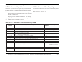
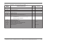
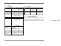
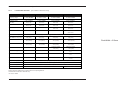
USER'S HANDBOOK
Model 9500B
High Performance Oscilloscope Calibrator
Operation and Performance
Final Width = 215mm
User's Handbook
For
The Model 9500B
High Performance Oscilloscope Calibrator
Operation and Performance
Final Width = 215mm
© 2005 Fluke Precision Measurement Ltd.
ISO 9002
Fluke Precision Measurement Ltd.
CERTIFICATE
No. FM 29700
Part No. 1625019
Issue 11.0
(October 2005)
For any assistance contact your nearest Fluke Sales and Service Center.
Addresses can be found at the back of this handbook.
Due to our policy of continuously updating our products, this handbook may contain minor
differences in specification, components and circuit design to the instrument actually supplied.
Amendment sheets precisely matched to your instrument serial number are available on request.
LIMITED WARRANTY AND LIMITATION OF LIABILITY
Each Fluke product is warranted to be free from defects in material and workmanship under normal use and service. The
warranty period is one year and begins on the date of shipment. Parts, product repairs, and services are warranted for 90 days.
This warranty extends only to the original buyer or end-user customer of a Fluke authorized reseller, and does not apply to fuses,
disposable batteries, or to any product which, in Fluke’s opinion, has been misused, altered, neglected, contaminated, or
damaged by accident or abnormal conditions of operation or handling. Fluke warrants that software will operate substantially
in accordance with its functional specifications for 90 days and that it has been properly recorded on non-defective media. Fluke
does not warrant that software will be error free or operate without interruption.
Fluke authorized resellers shall extend this warranty on new and unused products to end-user customers only but have no
authority to extend a greater or different warranty on behalf of Fluke. Warranty support is available only if product is purchased
through a Fluke authorized sales outlet or Buyer has paid the applicable international price. Fluke reserves the right to invoice
Buyer for importation costs of repair/replacement parts when product purchased in one country is submitted for repair in another
country.
Fluke’s warranty obligation is limited, at Fluke’s option, to refund of the purchase price, free of charge repair, or replacement
of a defective product which is returned to a Fluke authorized service center within the warranty period.
To obtain warranty service, contact your nearest Fluke authorized service center to obtain return authorization information, then
send the product to that service center, with a description of the difficulty, postage and insurance prepaid (FOB Destination).
Fluke assumes no risk for damage in transit. Following warranty repair, the product will be returned to Buyer, transportation
prepaid (FOB Destination). If Fluke determines that failure was caused by neglect, misuse, contamination, alteration, accident,
or abnormal condition of operation or handling, including overvoltage failures caused by use outside the product’s specified
rating, or normal wear and tear of mechanical components, Fluke will provide an estimate of repair costs and obtain authorization
before commencing the work. Following repair, the product will be returned to the Buyer transportation prepaid and the Buyer
will be billed for the repair and return transportation charges (FOB Shipping Point).
THIS WARRANTY IS BUYER’S SOLE AND EXCLUSIVE REMEDY AND IS IN LIEU OF ALL OTHER WARRANTIES,
EXPRESS OR IMPLIED, INCLUDING BUT NOT LIMITED TO ANY IMPLIED WARRANTY OF MERCHANTABILITY
OR FITNESS FOR A PARTICULAR PURPOSE. FLUKE SHALL NOT BE LIABLE FOR ANY SPECIAL, INDIRECT,
INCIDENTAL, OR CONSEQUENTIAL DAMAGES OR LOSSES, INCLUDING LOSS OF DATA, ARISING FROM ANY
CAUSE OR THEORY.
Since some countries or states do not allow limitation of the term of an implied warranty, or exclusion or limitation of incidental
or consequential damages, the limitations and exclusions of this warranty may not apply to every buyer. If any provision of this
Warranty is held invalid or unenforceable by a court or other decision-maker of competent jurisdiction, such holding will not
affect the validity or enforceability of any other provision.
Sept 1, 2001
Fluke reserves the right to amend specifications without notice.
Final Width = 215mm
Contents
Page
SAFETY ISSUES: READ THIS ENTIRE SECTION THOROUGHLY BEFORE ATTEMPTING TO
INSTALL, OPERATE OR SERVICE THE MODEL 9500B
0-8
Section 1 The Model 9500B High Performance Oscilloscope Calibrator
1.1 About Section 1 ............................................................................................................ 1-1
1.2 Introduction to the Model 9500B ................................................................................... 1-2
1.3 Model 9500B Associated Products and Options ........................................................... 1-4
Section 2 Installing the Model 9500B
2.1 About Section 2 ............................................................................................................ 2-1
2.2 Lifting and Carrying the Model 9500B .......................................................................... 2-1
2.3 Unpacking and Inspection ............................................................................................ 2-2
2.4 Storage ......................................................................................................................... 2-2
2.5 Preparation for Shipment .............................................................................................. 2-2
2.6 Calibration Enable Switch ............................................................................................. 2-2
2.7 Preparation for Operation ............................................................................................. 2-3
2.8 Connectors and Pin Designations ................................................................................ 2-7
2.9 Care of Microwave Connectors .................................................................................... 2-9
Section 3 Model 9500B Controls
3.1 About Section 3 ............................................................................................................ 3-1
3.2 Introduction to the Front Panel ..................................................................................... 3-2
3.3 Preferences .................................................................................................................. 3-6
3.4 Modes of Operation ...................................................................................................... 3-8
Final Width = 215mm
Section 4 Using the Model 9500B — Manual Mode
4.1 About Section 4 ............................................................................................................ 4.1-1
4.2 Interconnections ........................................................................................................... 4.2-1
4.3 Manual Mode — Function Selection ............................................................................. 4.3-1
4.4 Edit Facilities ................................................................................................................ 4.4-1
Functions:
4.5 DC/Square Function ..................................................................................................... 4.5-1
4.6 Levelled Sine Function ................................................................................................. 4.6-1
4.7 Edge Function ............................................................................................................... 4.7-1
4.8 Time Markers Function ................................................................................................. 4.8-1
4.9 Auxiliary Functions ....................................................................................................... 4.9-1
4.10 Current Function ........................................................................................................... 4.10-1
4.11 Composite Video Function ............................................................................................ 4.11-1
4.12 Linear Ramp Function .................................................................................................. 4.12-1
4.13 Overload Pulse Function .............................................................................................. 4.13-1
4.14 Zero Skew Function ...................................................................................................... 4.14-1
4.15 Auxiliary Input Function ................................................................................................ 4.15-1
4.16 Load Resistance and Capacitance Measurement Function ......................................... 4.16-1
4.17 Input Leakage Function ................................................................................................ 4.17-1
4.18 Pulse Width Function .................................................................................................... 4.18-1
0-4
Model 9500B User's Handbook — Contents List
Page
Section 5 Using the Model 9500B — Procedure Mode
5.1 About Section 5 ............................................................................................................ 5.1-1
5.2 Procedure Mode — Safety and General Notes ............................................................ 5.2-1
5.3 Procedure Mode — Access Guide ............................................................................... 5.3-1
Section 6 9500B System Application via IEEE-488 Interface
6.1 About Section 6 and Section 6 Contents ...................................................................... 6.1-1
6.2 Index of IEEE-488.2 and SCPI Codes used in the Model 9500B ................................. 6.2-1
6.3 Introduction ................................................................................................................... 6.3-1
6.4 Using the 9500B in a System ....................................................................................... 6.4-1
6.5 Retrieval of Device Status Information ......................................................................... 6.5-1
6.6 9500B SCPI Language - Commands and Syntax ........................................................ 6.6-1
Section 6 Appendix A: IEEE 488.2 Device Documentation Requirements ........................... 6-A1
Section 6 Appendix C: IEEE 488.2 Common Commands and Queries
Implemented in the Model 9500B ..................................................... 6-C1
Section 6 Appendix D: Model 9500B — Device Settings after *RST & Power On ................ 6-D1
Section 6 Appendix F: Model 9500B —
Emulation of Tektronix SG5030 and CG5010/5011 .......................... 6-F1
Section 7 Model 9500B Specifications
7.1 General ......................................................................................................................... 7-1
7.2 Accuracy Specifications ................................................................................................ 7-1
7.3 Voltage Function Specifications .................................................................................... 7-2
7.4 Edge Function Specifications ....................................................................................... 7-3
7.5 Time Markers Function Specifications .......................................................................... 7-4
7.6 Levelled Sine Function Specifications .......................................................................... 7-5
7.7 Dual Sine Function Specifications ................................................................................ 7-6
7.8 Pulse Width Function Specifications ............................................................................. 7-7
7.9 Other Output Function Specifications ........................................................................... 7-8
7.10 Trigger Output Specifications ........................................................................................ 7-10
Final Width = 215mm
Section 8 Model 9500B — Routine Maintenance and Test
8.1 About Section 8 ............................................................................................................ 8-1
8.2 Routine Maintenance .................................................................................................... 8-2
8.3 Model 9500B Test and Selftest ..................................................................................... 8-4
8.4 Printing Selftest Results ................................................................................................ 8-10
Section 8 Appendix A: Error Reporting Subsystem .............................................................. 8-A1
Model 9500B User's Handbook — Contents List
0-5
Page
Section 9 Verifying the Model 9500B Specification
9.1 About Section 9 ............................................................................................................ 9-1
9.2 Need for Verification ..................................................................................................... 9-1
9.2.1 Factory Calibration and Traceability ................................................................. 9-1
9.2.2 Verification on Receipt from the Factory .......................................................... 9-1
9.2.3 Verification after User-Calibration .................................................................... 9-1
9.3 Equipment Requirements ............................................................................................. 9-1
9.4 Interconnections ........................................................................................................... 9-1
9.5 Verification Points ......................................................................................................... 9-1
9.6 Specification Limits ....................................................................................................... 9-2
9.7 Verification Procedure .................................................................................................. 9-2
9.8 9500B Mainframe Verification by Functions
9.8.1 Verifying the DC/Square Function: DC Voltage ............................................... 9-2
9.8.2 Verifying the DC/Square Function: Square Voltage ......................................... 9-6
9.8.3 Verifying the LF Sine Voltage Function ............................................................ 9-10
9.8.4 Verifying the Time Markers Function ................................................................ 9-13
9.8.5 Verifying the Load Resistance Measurement Function .................................... 9-15
9.8.6 Verifying the Pulse Width Function .................................................................. 9-18
9.9 9510/9530/9550/9560 Head Verification by Functions
9.9.1 Verifying the Levelled Sine Voltage Function: LF Gain .................................... 9-20
9.9.2 Verifying the Levelled Sine Voltage Function: Flatness ................................... 9-23
9.9.3 Verifying the Edge Function ............................................................................. 9-29
9.9.4 Verifying the Load Capacitance Measurement Function ................................. 9-33
Section 10 Calibrating the Model 9500B
10.1 About Section 10 and Section 10 Contents ................................................................. 10.1-1
10.2 9500B Mainframe Calibration and Active Head™ Calibration ..................................... 10.2-1
10.2.1 Introduction ...................................................................................................... 10.2-1
10.2.2 Mainframe Unit Calibration .............................................................................. 10.2-1
10.2.3 Active Head Calibration ................................................................................... 10.2-1
10.2.4 Other Functions .............................................................................................. 10.2-1
10.2.5 Mainframe Unit Manual Calibration ................................................................. 10.2-1
10.3 The Model 9500B Calibration Mode ............................................................................. 10.3-1
10.3.1 Introduction ...................................................................................................... 10.3-1
10.3.2 Mode Selection ................................................................................................ 10.3-2
10.3.3 Selection of Calibration Mode .......................................................................... 10.3-2
10.3.4 Special Calibration ........................................................................................... 10.3-3
10.3.5 Special Cal: 'Adjust FREQ' ............................................................................... 10.3-4
10.3.6 Mainframe Standard Calibration (STD CAL) .................................................... 10.3-5
10.3.7 Overview of Calibration Operations ................................................................. 10.3-6
10.4 Standard Calibration — Basic Sequences .................................................................... 10.4-1
10.4.1 Introduction ...................................................................................................... 10.4-2
10.4.2 Target Selection Screen — Selecting Hardware Configurations ..................... 10.4-2
10.4.3 The Adjustment Screen .................................................................................... 10.4-3
10.4.4 Calibrating the Model 9500B at Target Values ................................................. 10.4-4
10.4.5 Standard Calibration of AC Functions .............................................................. 10.4-5
10.4.6 Exit from Calibration - Cal Date and Cal Due Date .......................................... 10.4-6
Final Width = 215mm
0-6
Model 9500B User's Handbook — Contents List
Page
Section 10 Calibrating the Model 9500B - Cont.
10.5 Front Panel Calibration by Functions ........................................................................... 10.5-1
10.5.1 Introduction ...................................................................................................... 10.5-1
10.5.2 Summary of Calibration Process ..................................................................... 10.5-2
10.5.3 DC/Square — DC Voltage Calibration ............................................................. 10.5-4
10.5.4 DC/Square — Square Calibration .................................................................... 10.5-8
10.5.5 LF Sine Voltage Calibration ............................................................................. 10.5-13
10.5.6 Load Resistance Measurement Calibration ..................................................... 10.5-16
10.6 9510/9530/9550/9560 Head Calibration Procedures ................................................... 10.6-1
10.6
Introduction ...................................................................................................... 10.6-1
10.6.1 Levelled Sine Function: LF Gain ...................................................................... 10.6-1
10.6.2 Levelled Sine Function: HF Calibration ............................................................ 10.6-3
10.6.3 Edge Function Calibration ................................................................................ 10.6-7
10.6.4 Calibrating the Timing Markers ........................................................................ 10.6-13
10.6.5 Load Capacitance Calibration .......................................................................... 10.6-14
10.6.6 50W/1MW Ratio Calibration ............................................................................. 10.6-15
10.6.7 Exit from Head Calibration ............................................................................... 10.6-16
Fluke's Regional Sales & Service Centers
Final Width = 215mm
Inside Rear Cover
Model 9500B User's Handbook — Contents List
0-7
SAFETY ISSUES
READ THIS ENTIRE SECTION THOROUGHLY BEFORE ATTEMPTING TO INSTALL, OPERATE OR SERVICE THE MODEL 9500B
General Safety Summary
This instrument has been designed and tested in accordance with
the British and European standard publication EN61010:1993/
A2:1995, and has been supplied in a safe condition.
Explanation of safety related
symbols and terms
DANGER
electric shock risk
The product is marked with this symbol to indicate
that hazardous voltages (>30 VDC or AC peak)
may be present.
This manual contains information and warnings that must be
observed to keep the instrument in a safe condition and ensure
safe operation. Operation or service in conditions or in a manner
other than specified could compromise safety. For the correct
and safe use of this instrument, operating and service personnel
must follow generally accepted safety procedures, in addition to
the safety precautions specified.
Final Width = 215mm
CAUTION
refer to documentation
The product is marked with this symbol when the
user must refer to the instruction manual.
To avoid injury or fire hazard, do not switch on the instrument
if it is damaged or suspected to be faulty. Do not use the
instrument in damp, wet, condensing, dusty, or explosive gas
environments.
Whenever it is likely that safety protection has been impaired,
make the instrument inoperative and secure it against any
unintended operation. Inform qualified maintenance or repair
personnel. Safety protection is likely to be impaired if, for
example, the instrument shows visible damage, or fails to
operate normally.
WARNING THIS INSTRUMENT CAN DELIVER A
LETHAL ELECTRIC SHOCK. NEVER
TOUCH ANY LEAD OR TERMINAL
UNLESS YOU ARE ABSOLUTELY
CERTAIN THAT NO DANGEROUS
VOLTAGE IS PRESENT.
0-8
Model 9500B User's Handbook — Safety Section
Earth (Ground) terminal
Functional Earth (Ground) only - must not be
used as a Protective Earth.
WARNING WARNING STATEMENTS IDENTIFY
CONDITIONS OR PRACTICES THAT
COULD RESULT IN INJURY OR DEATH.
CAUTION
CAUTION STATEMENTS IDENTIFY
CONDITIONS OR PRACTICES THAT
COULD RESULT IN DAMAGE TO THIS
OR OTHER PROPERTY.
Protective Earth (Ground)
Protection Class I:
Safe Operating Conditions
The instrument must be operated with a Protective Earth/
Ground connected via the power cable's protective earth/ground
conductor. The Protective Earth/Ground connects to the
instrument before the line & neutral connections when the
supply plug is inserted into the power socket on the back of the
instrument.
Only operate the instrument within the manufacturer's specified
operating conditions. Specification examples that must be
considered include:
WARNING ANY
INTERRUPTION
OF
THE
PROTECTIVE GROUND CONDUCTOR
INSIDE OR OUTSIDE THE INSTRUMENT
IS LIKELY TO MAKE THE INSTRUMENT
DANGEROUS.
To avoid electric shock hazard, make signal connections to the
instrument after making the protective ground connection.
Remove signal connections before removing the protective
ground connection, i.e. the power cable must be connected
whenever signal leads are connected.
ambient temperature
ambient humidity
power supply voltage & frequency
maximum terminal voltages or currents
altitude
ambient pollution level
exposure to shock and vibration
To avoid electric shock or fire hazard, do not apply to or subject
the instrument to any condition that is outside specified range.
See Section 6 of this manual for detailed instrument specifications
and operating conditions.
CAUTION
CONSIDER
DIRECT
SUNLIGHT,
RADIATORS AND OTHER HEAT
SOURCES WHEN ASSESSING AMBIENT
TEMPERATURE.
CAUTION
BEFORE
CONNECTING
THE
INSTRUMENT TO THE SUPPLY, MAKE
SURE THAT THE REAR PANEL AC
SUPPLY VOLTAGE CONNECTOR IS SET
TO THE CORRECT VOLTAGE AND THAT
THE CORRECT FUSES ARE FITTED.
Do Not Operate Without Covers
To avoid electric shock or fire hazard, do not operate the
instrument with its covers removed. The covers protect users
from live parts, and unless otherwise stated, must only be
removed by qualified service personnel for maintenance and
repair purposes.
WARNING REMOVING THE COVERS MAY EXPOSE
VOLTAGES IN EXCESS OF 1.5KV PEAK
(MORE UNDER FAULT CONDITIONS).
continued overleaf
Model 9500B User's Handbook — Safety Section
0-9
Final Width = 215mm
The Power Cable and Power Supply
Disconnection
Installation Category I:
The intended power supply disconnect device is the ON/OFF
switch that is located on the instrument's rear panel. The ON/
OFF switch must be readily accessible while the instrument is
operating. If this operating condition cannot be met, the power
cable plug or other power disconnecting device must be readily
accessible to the operator.
Measurement and/or guard terminals are designed for connection
at Installation (Overvoltage) Category I. To avoid electric shock
or fire hazard, the instrument terminals must not be directly
connected to the AC line power supply, or to any other voltage
or current source that may (even temporarily) exceed the
instrument's peak ratings.
To avoid electric shock and fire hazard, make sure that the power
cable is not damaged, and that it is adequately rated against
power supply network fusing. If the power cable plug is to be the
accessible disconnect device, the power cable must not be
longer than 3 metres.
WARNING TO AVOID INJURY OR DEATH, DO NOT
CONNECT OR DISCONNECT SIGNAL
LEADS WHILE THEY ARE CONNECTED
TO A HAZARDOUS VOLTAGE OR
CURRENT SOURCE. MAKE SURE THAT
ALL LEADS ARE IN A SAFE CONDITION
BEFORE YOU HANDLE THEM IN ANY
WAY.
Power Input & Fuse Requirements
Final Width = 215mm
To avoid fire hazard, use only the fuse arrangements that appear
in the fuse specification table below. Additionally, the supply
network must be fused at a maximum of 16A, and in the UK, a
10A fuse must be fitted in the power cable plug See Section 2.7
for details of setting line input voltage and changing the line
input fuse.
Make sure that the instrument is correctly protectively earthed
(safety grounded) via the power cable before and while any
other connection is made.
Power Input Fuse
0-10
Supply (Line)
Voltage Selection
Fuse Action
115 VAC
TH
230 VAC
TH
Fuse Rating
(IEC)
Fluke
Part No.
Manufacturer
& Type No.
10A
920274
Littlefuse 215010.
5A
920273
Littlefuse 215005.
Model 9500B User's Handbook — Safety Section
Maintenance and Repair
Moving and Cleaning
Observe all applicable local and/or national safety regulations
and rules while performing any work. First disconnect the
instrument from all signal sources, then from the AC line supply
before removing any cover. Any adjustment, parts replacement,
maintenance or repair should be carried out only by the
manufacturer's authorised technical personnel.
First disconnect the instrument from all signal sources, then
from the AC line supply before moving or cleaning. See Section
8.2 for Routine Maintenance procedures.
WARNING FOR PROTECTION AGAINST INJURY
AND FIRE HAZARD, USE ONLY
MANUFACTURER SUPPLIED PARTS
THAT ARE RELEVANT TO SAFETY.
PERFORM SAFETY TESTS AFTER
REPLACING ANY PART THAT IS
RELEVANT TO SAFETY.
Final Width = 215mm
Observe any additional safety instructions or warnings given in this manual.
Model 9500B User's Handbook — Safety Section
0-11
This page deliberately left blank
This page deliberately left blank
BLANK PAGE (LEFT-HAND)
Final Width = 215mm
Section 1
The Model 9500B High Performance Oscilloscope Calibrator
Final Width = 215mm
Fig. 1.1 General View of Model 9500B with an Active Head
1.1
About Section 1
Section 1 introduces the Model 9500B High Performance Oscilloscope
Calibrator. It is divided into the following sub-sections:
1.2 Introducing the Model 9500B
Page
1.2.1 Variants .............................................................. 1.1
1.2.1 Functions ........................................................... 1.2
1.2.2 Operating Modes ............................................... 1-3
1.2.2.1 Manual Mode .................................... 1-3
1.2.2.2 Procedure Mode................................ 1-3
1.2.2.3 Configuration Mode .......................... 1-3
1.2.2.4 Calibration Mode .............................. 1-3
1.2.2.5 Test Mode ......................................... 1-4
1.2.3 System Operation .............................................. 1-4
1.2.3.1 Remote Interface ............................... 1-4
1.2.3.2 Portocal II.......................................... 1-4
1.3 Model 9500B Associated Products and Options
1-4
Descriptions assume 9500B/1100
1.2
Introduction to the Model 9500B
1.2.1
Functions
The Model 9500B is a state-of-the-art calibrator offering oscilloscope test and
calibration capabilities from a single source, providing wide functionality.
(Variant 9500B/1100 is described — for other variants, refer to their specifications
in Section 7.) The functions listed overleaf are not necessarily available via
every model of Active Head.
Section 1: Introducing the Model 9500B
1-1
1.2.1
•
Functions (Contd.)
DC Function:
(into 50Ω):
(into 1MΩ):
±(888µV to 5.56V)
±(888µV to 222.4V)
Frequencies:
Output Voltage:
Output Voltage:
10Hz to 100kHz
(pk-pk into 50Ω):
(pk-pk into 1MΩ Load):
35.52µV to 5.56V
35.52µV to 222.4V
Sine Function
(Variant 9500B/1100 quoted below);
(see Sect. 7 for specifications of other variants):
100mHz to 550MHz
(pk-pk into 50Ω & 1MΩ):
4.44mV to 5.56V
550MHz to 1.1GHz
(pk-pk into 50Ω & 1M):
4.44mV to 3.35V
Output Voltage:
Output Voltage:
•
•
Final Width = 215mm
•
•
Output Current:
Square:
Frequencies:
Output Current:
±(88.8µA to 111.2mA)
10Hz to 100kHz
88.8µA pk-pk to 111.2mA pk-pk
Section 1: Introducing the Model 9500B
Linear Ramp Function:
Overload Pulse Function:
Pulse Amplitude:
Pulse Energy:
Polarity:
Pulse Duration:
Power into 50Ω:
Repetition Rate:
UUT Scope Trigger:
•
5.0V to 20.0V (0.1V resolution)
1.6J to 50.0J (0.1J resolution)
Positive or negative from ground
at 20V: 200ms to 6.25s; at 5V: 3.2s to 100s
(Internally calculated from Amplitude and Energy)
0.5W to 8W (Internally calculated from Amplitude)
Single manually-triggered event, max repetition rate 0.3Hz.
With energy pulse, or Auto trigger at 100Hz
Zero Skew Function:
Frequencies:
Default Alignment:
Align 9500B Channel Output Timing:
Measure UUT Scope Channel Skew:
•
Impedance:
3dB Bandwidth:
Trigger:
•
1pF to 120pF.
1MHz to 20MHz in 1MHz integer steps.
70mV pk-pk to 1V pk-pk.
Reference Frequency Output:
Frequency Range:
Level into 50Ω:
Level into 1MΩ:
•
10kΩ to 20MΩ.
10Ω to 150Ω.
Reference Frequency Input:
Frequency Range:
Amplitude Range:
•
Automated, passive, relay-switched routing of user's external
calibration waveforms to any Active Head's BNC connector
via the output multiplexer.
Input and Output: 50Ω.
Approx. 400MHz.
No trigger pickoff provided, internal trigger not available.
Load Resistance and Capacitance Measurement:
Resistance Range:
Input:
Termination:
Capacitance:
Range:
•
10Hz to 100MHz.
9500B output channel skew = ≤50ps.
Using a single oscilloscope channel.
Using aligned 9500B channels.
Auxiliary Input:
Signal Path:
Current Function:
DC:
1-2
1Vpk-pk into 50W
1ns to 100ns
<500ps
1kHz to 1MHz
Positive and Negative sync
Full Raster Selectable: White, Mid Grey or Black.
White: 1V, mid-grey: 0.7V, black: 0.3V. No deviation.
625 lines/50Hz, 525 lines/60Hz
Calibrator trigger output selectable to Odd Field Start, or
Composite Sync.
Period:
3s, 300ms, 30ms, 3ms.
Ramps:
Equal Rise, Fall and Flat divisions per cycle.
Amplitude: 1V pk-pk
Bias:
Symmetrical about ground
Trigger Alignment:
Start of rising or falling ramp
•
Pulse Width Function:
Amplitude:
Pulse Width:
Rise/Fall Time:
Frequency:
•
•
Edge Function:
Selectable Rising/Falling Edge
Low Edge:
500ps: Active Head Model 9510 or 9530
Periods:
500ns to 100ms
Output Voltage:
(pk-pk into 50Ω &1MΩ):
4.44mV to 3.1V
High Edge:
100ns: Active Head Model 9510 or 9530
Periods:
10µs to 100ms
Output Voltage:
(pk-pk into 50Ω):
888mV to 5.56V
(pk-pk into 1MΩ):
888mV to 222.4V
Fast Edge:
150ps: Active Head Model or 9530
Periods:
500ns to 100ms
Output Voltage:
(pk-pk into 50Ω &1MΩ):
4.44mV to 3.1V
Time Markers Function (Output Voltage pk-pk into 50Ω & 1M)
Square/Sine Waveforms (Variant 9500B/1100 quoted below);
(see Sect. 7 for specifications of other variants):
Squarewave Periods:
9.0091ns to 55s
(111MHz to 18.181mHz)
(Highlighted style):
20ns to 55s
(50MHz to 18.181mHz)
Output Voltage:
100mV to 1.0V
Sinewave Periods:
450.5ps to 9.009ns
(2.22GHz to 111MHz)
Output Voltage:
100mV to 500mV
Sinewave Periods:
909.1ps to 9.009ns
(1.1GHz to 111MHz)
Output Voltage:
1.0V
Pulse and Triangle Waveforms:
Periods:
900.91ns to 55s
(1.11MHz to 18.181mHz)
(Highlighted style):
20ns to 55s
(50MHz to 18.181mHz)
Output Voltage:
100mV to 1.0V
Composite Video Function:
Polarity:
Patterns:
Amplitude Levels p-p:
Frame Standards:
Trigger:
Square Function:
Frequencies:
Output Voltage:
Frequencies:
Output Voltage:
Dual Channel
•
•
1MHz or 10MHz.
>1.15V.
>2.3V.
Input Leakage Function:
Short/Open Circuit Outputs:
UUT Scope Trigger:
Allows testing of UUT oscilloscope input leakage
current.
Auto trigger at 100Hz
Descriptions assume 9500B/1100
1.2.2
Operating Modes
In order to be able to calibrate a wide range of different oscilloscope
parameters, flexibility is built into the design of the 9500B. Of the five
major modes only two: 'Manual' and 'Procedure', determine the everyday
front-panel use of the instrument. The other three are concerned with
system configuration, 9500B calibration and 9500B selftest.
1.2.2.1
Manual Mode
In 'Manual' Mode: the 9500B is operated entirely from the front panel.
The operator is in complete charge of the calibration procedure, usually
interpreted locally from the UUT oscilloscope manufacturer's calibration
data. Refer to Sections 3 and 4.
1.2.2.2
Procedure Mode
'Procedure' Mode involves the use of a memorized calibration procedure.
The manufacturer's data for the UUT oscilloscope will have been
interpreted into a series of calibration operations, which are programmed
on to a memory card. When the card is inserted into the 'PROCEDURE'
slot in the front panel, the 9500B will move from operation to operation,
switching the 9500B controls automatically, and issuing a series of
requests for the operator to change UUT switching and connections.
Refer to Section 5.
Portocal II v 1.7 (see paras 1.3) can be used to generate calibration
sequences on procedure cards to calibrate UUT oscilloscopes using the
Model 9500B.
1.2.2.3
Configuration Mode
This mode, requiring a password, provides access for the user-selectable
configuration options. These include:
• Set the internal reference frequency.
• Adjust the threshold for high voltage warning.
• Change the IEEE-488 bus addresses.
• Select or deselect remote emulation (SG5030 or CG5010/5011).
• Enable or disable use of an external printer (Procedure mode only).
• Set the instrument to power-up in either Manual or Procedure mode.
• Alter the passwords required for entry to Configuration and
Calibration modes.
• Select the frequency for External Reference Input.
• Set the frequency of, or disable, External Reference Output.
• Alter the memorized date and time, and its format of presentation.
• Set User language (for Procedure mode only).
• Determine the percentage of UUT measurement tolerance beyond
which a 'Borderline' result is called (in Procedure mode only).
•
•
•
•
Enable or disable the use of a data card for 'RESULTS' (Procedure
mode only).
Enable or disable fields in certificates to accommodate Engineer's
note (Procedure mode only).
Select the type of certificate required to be printed, alter some of the
certificate details, and re-format its pages (Procedure mode only).
Clear the displayed list of Procedure mode users.
1.2.2.4
Calibration Mode
Calibration of the 9500B itself cannot proceed until two security
measures have been satisfied:
1. The rear panel 'CAL' switch must be set to its 'ENABLE' position.
Note: The switch is recessed behind a small hole — at shipment this
hole is covered by a paper seal which should not be broken
except for an authorized recalibration.
A broken seal is regarded as invalidating the previous
calibration.
2. An acceptable password must be entered on the screen.
Final Width = 215mm
Once into Calibration mode, there are three types of calibration available.
These should be used only under supervision — if it is suspected that
calibration may be required, contact your Fluke Service Center.
•
'Special' calibration, enabling automatic calibration of the main
A-D converter.
•
'Factory use only' is an initial calibration which is not available to
users, requiring a second password.
•
'Standard Calibration' will initiate manual calibration procedures
for those functions requiring recalibration.
Calibration of the 9500B is detailed in Section 9: 'Specification
Verification' and Section 10: 'Calibration' (Adjustment). Those 9500B
calibration sequences which are user-accessible are detailed in Section
10. If it is suspected that some other calibration may be required,
contact your Fluke Service Center.
Test Mode overleaf→
Descriptions assume 9500B/1100
Section 1: Introducing the Model 9500B
1-3
1.3
Final Width = 215mm
1.2.2.5
Test Mode
Three main variants of self test are available for user initiation:
• 'Base' Test:
Tests the base unit only. No head data is tested.
• 'Heads' Test:
Tests the fitted Active Heads only, assuming that
base tests have been passed.
• 'All' Test:
Tests both the base unit and active heads fitted.
Note: In the above three tests, the 9500B will keep a list of all test
failures, including the number of the test and its result. Any
failures can then be recalled using screen keys.
• 'Fast' Test:
This is the same as the confidence test carried out
at power-on, checking power supplies, basic
operation, etc.
• 'Interface' Test: This can be used to check the operation of the
display and its memory, the keyboard and/or printer
connected to the instrument. A blank memory card
inserted in either slot on the front panel can also be
tested (WARNING!: the stored contents of any
memory card subjected to this test will be overwritten!).
It is possible to print out a set of results of selftests. A printer can be
connected directly to the 25-way Centronics™ printer port on the rear
panel. The printer can be enabled from within Configuration mode.
Test procedures and error-code descriptions are given in Section 8. In
the case of a reported or suspected failure, consult your Fluke Service
Center.
1.2.3
1. Active Head™
At least one unit of the following products is necessary to complete the
output connection from the 9500B output channel to one channel of the
UUT oscilloscope.
Model 9510
Model 9530
Model 9550
Model 9560
1.1GHz Output Module (Active Head™) with 500ps
pulse edge capability.
3.2GHz Output Module (Active Head™) with 150ps
and 500ps pulse edge capabilities.
25ps Fast Edge Output Module (Active Head TM) with
25ps pulse edge capability only.
6.4GHz Output Module (Active Head TM) with 70ps
pulse edge capability. Requires 9500-3200 or 9500B3200 base with issue 3.0 firmware or greater.
Check the last section of this manual for an Addendum that describes
any additional Active Head models.
Any one of the fitted heads can be used to provide triggers for the UUT
oscilloscope instead of signals. However, a Trigger Cable (SMC-toBNC) is shipped with the 9500B to provide triggers to a separate trigger
input on the UUT oscilloscope, with a mix of up to four active heads.
2. The following accessories are shipped with the instrument:
Pt. No.
401297
630477
System Operation
1.2.3.1
Remote Interface
The instrument can form part of an automated system by means of the
IEEE-488 standard digital interface. The interface has been included
both for automatic calibration of UUT oscilloscopes, and for automatic
calibration of the 9500B itself. The method of connecting to the system
controller and the IEEE-488.2 SCPI command codes are described in
Section 6.
Emulation of the SG5030 and CG5010/5011 is available only via the
remote IEEE-488 interface, as detailed in Section 6, Appendix F.
Model 9500B Associated Products
and Options
Description
Current Loop Assembly for use in Current Function.
Trigger Cable for trigger purposes only, in place of an
Active Head™.
3. The available options for the 9500B are as follows:
Option 60
Option 90
Carry Case.
Rack Mounting Kit.
Line Voltage: The 9500B is configured for use at the correct voltage
at the shipment point. The 9500B can be reconfigured
for a different line voltage, requiring a different power
fuse (Refer to Section 2, paras 2.7.4 and 2.7.5).
1.2.4.2
Met/Cal II
The 9500B is included in the number of calibrators accessible through
Met/Cal II which can be used to calibrate UUT oscilloscopes remotely.
1-4
Section 1: Introducing the Model 9500B
Descriptions assume 9500B/1100
Section 2
2.1
Installing the Model 9500B
About Section 2
Section 2 contains information and instructions for unpacking and
installing the Model 9500B Universal Calibration System. It is divided
into the following sub-sections:
2.2
page
Lifting and Carrying the Model 9500B
2.2.1 Lifting and Carrying from Bench Height ................................. 2-1
2.2.2 Lifting and Putting Down at Low Level ................................... 2-1
2.3
Unpacking and Inspection ................................................................... 2-2
2.4
Storage
2.5
Preparation for Shipment .................................................................... 2-2
2.6
Calibration Enable Switch ................................................................... 2-2
2.7
Preparation for Operation .................................................................... 2-3
2.7.1
2.7.2
2.7.3
2.7.4
2.7.5
2.8
Mounting ................................................................................ 2-4
2.7.1.1 Bench Mounting ..................................................... 2-4
2.7.1.2 Rack Mounting ....................................................... 2-4
Power Input ............................................................................ 2-6
Power Cable ........................................................................... 2-6
Power Fuse ............................................................................ 2-6
Line Voltage ........................................................................... 2-7
Connectors and Pin Designations
2.8.1
2.8.2
2.8.3
2.8.4
2.8.5
2.8.6
2.9
............................................................................... 2-2
IEEE-488 Input/Output Socket ............................................... 2-7
Parallel Port ............................................................................ 2-8
Serial Port .............................................................................. 2-8
Auxiliary Input ......................................................................... 2-9
Ref Frequency Input ............................................................... 2-9
Ref Frequency Output ............................................................ 2-9
2.2
Lifting and Carrying the 9500B
Caution!
2.2.1
The 9500B weighs in excess of 12kg, so take special
care when lifting and carrying the instrument.
Lifting and Carrying from Bench Height
1. Disconnect and remove any cables from the rear panel.
2. The 9500B center of gravity is concentrated at the rear. Tilt the unit
so that it is standing vertically on its rear panel, with the feet towards
you, at the edge of the bench.
3. Grasp the instrument at the bottom (rear panel) corner furthest away
from you, and tilt it slightly to rest against you. Take the weight and
carry it vertically at the same height, making sure that it remains
resting against you.
4. Place the 9500B down at the same level by setting it vertically on
to the surface, then swivel it so that it can be tilted back on to its feet.
2.2.2
Lifting and Putting Down at Low Level
1. Always bend your knees, not your back, when going down. Keep
your back as straight and as vertical as possible.
2. Use the same technique (2.2.1 - 3 above) to hold the instrument's
center of gravity close to you.
Care of Microwave Connectors ........................................................... 2-9
Section 2: Installing the Model 9500B
2-1
2.3
Unpacking and
Inspection
Every care is taken in the choice of packing
materials to ensure that your equipment will
reach you in perfect condition.
If the equipment has been subject to excessive
mishandling in transit, the fact will probably
be visible as external damage to the shipping
container and inner carton. In the event of
damage, the shipping container, inner carton
and cushioning material should be kept for the
carrier’s inspection.
Carefully unpack the equipment and check for
external damage to the case, sockets, controls,
etc. If the shipping container and cushioning
material are undamaged, they should be
retained for use in subsequent shipments. If
damage is found notify the carrier and your
sales representative immediately.
Standard accessories (associated products and
options) supplied with the instrument should
be as described in Section 1 and on your
delivery note.
2.4
2.5
If the 9500B is to be transported, please consider
using the carry case, Option 60.
The instrument should be transported under
cover. The original (double) shipping container
should be used to provide shock isolation for
normal handling operations. Any other
container should be double-cushioned,
providing similar shock isolation to the
following approximate internal packing
dimensions:
Length
Outer Box
785mm
Inner Box
675mm
Cushioned to 460mm
Width
675mm
565mm
430mm
Depth
440mm
315mm
145mm
Place the instrument with an active desiccant
sachet inside a sealed bag. Fit the bag into the
cushioning material inside the inner carton,
place this within the corner cushioning blocks
inside the outer shipping container, and secure
the whole package.
Storage
The instrument should be stored under cover.
The shipping container provides the most
suitable receptacle for storage, as it provides
the necessary shock isolation for normal
handling operations.
Place the instrument with an active desiccant
sachet inside a sealed bag. Fit the bag into the
cushioning material inside the inner carton,
place this within the corner cushioning blocks
inside the outer shipping container, and locate
the whole package within the specified storage
environment.
2-2
Preparation for
Shipment
Section 2: Installing the Model 9500B
2.6
Calibration Enable
Switch
IMPORTANT
This two-position, 'CAL' switch on the rear
panel protects the instrument calibration
memory. The instrument was initially
calibrated at the factory, so under no
circumstances should the switch be operated,
until immediate recalibration is intended.
For Recalibration:
If Calibration Mode is entered while the switch
is in the 'DISABLE' position, the following
warning message is placed on the screen:
Calibration switch not enabled!
2.7
Preparation for Operation
IMPORTANT:
Refer to the Safety Issues section at the front of this manual, together with additional information in the Model 9500B General Specifications,
including Environmental Conditions: Section 7, sub-section 7.1.
Before preparing the Model 9500B calibrator for operation, note the danger warning:
DANGER
THIS INSTRUMENT IS CAPABLE OF DELIVERING AN ELECTRIC SHOCK. UNDER NO CIRCUMSTANCES TOUCH ANY
INSTRUMENT TERMINAL UNLESS YOU ARE FIRST SATISFIED THAT NO DANGEROUS VOLTAGE IS PRESENT.
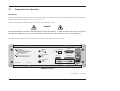
Other than the main output active head connectors, the connections to the 9500B are via the rear panel:
SAFETY WARNING
1) DISCONNECT POWER AND SIGNAL LEADS
BEFORE REMOVING COVERS.
2) FOR CONTINUED PROTECTION AGAINST ELECTRIC SHOCK
THE POWER CORD PROTECTIVE CONDUCTOR MUST BE
CONNECTED TO EARTH (GROUND).
3) FOR CONTINUED PROTECTION AGAINST FIRE
FIT 250V FUSE OF CORRECT RATING
NOTE.
NO USER SERVICEABLE PARTS CONTAINED. DO NOT
REMOVE COVERS, HAZARDOUS VOLTAGES PRESENT.
REFER SERVICE TO QUALIFIED PERSONNEL.
CAL
AUXILIARY
INPUT
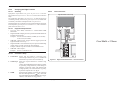
ENABLE
≤ 40Vpk
DISABLE
IEEE-488
678
SH1 AH1 T6 L4 SR1
RL1 PP0 DC1 DT0 C0 E2
REF FREQUENCY
INPUT
≤ 5Vpk
50Ω
REF FREQUENCY
OUTPUT
1V pk-pk nom
into 50Ω
MADE IN THE EC
FACTORY SET
CALIBRATION SEAL
SERIAL PORT
PARALLEL PORT
LINE VOLTAGE
SELECTION
FUSE 5 x 20mm
IEC 127
100V/ 120V
220V/ 240V
T10.0 AH
T5.0 AH
POWER INPUT
400VA max FREQUENCY 47- 63 Hz
9500B Rear Panel
2.7.1 Mounting: overleaf→
Section 2: Installing the Model 9500B
2-3
2.7
Preparation for Operation (Contd.)
2.7.1
Mounting
2.7.1.1
Bench Mounting
The instrument is fitted with four plastic feet
and a tilt stand. It can stand flat on a bench,
positioned so that the cooling-air inlet on the
right side and exhaust apertures on the left side
are not obstructed.
2-4
2.7.1.2
Option 90 — Rack Mounting (Fig. 2.1)
Option 90 permits the instrument to be mounted C. Removing the 9500B Feet and Tilt Stand
in a standard 19 inch rack. The method of (if required)
fitting this option is described below, the Remove the feet and tilt stand:
locations being shown in Fig. 2.1.
a. Prize off the rubber pads from the four
feet.
A. Provision of Option 90
b. Undo the two securing screws from
1. Option 90 is provided with all necessary
each foot. This releases the feet,
attachments and fixings.
washers and tilt stand so that they can
2. The 9500B is fitted with side extrusions
be detached and stored safely for
with holes to accommodate rack mounting
possible future use.
fixing screws.
D. Fitting the Rear Ears to the Rack
B. Fitting the Mountings to the 9500B
Fit the left and right rear ears (not
1. Fit left and right front rack mounting ears
interchangeable)
to the rack:
(these are interchangeable) to the 9500B:
a.
Fit
the
eight
M6 cage nuts into the
a. Assemble the handles to the front ears
correct
cutouts
at front and rear of the
as shown in the diagram, and secure
rack (see Fig. 2.1). Squeeze the cage
using the four M4 x 12 POZICSK
on each nut and insert from the inside
screws provided.
of the rack.
b. Secure the front ears through the side
b. Offer up each appropriate ear to the
extrusions to the chassis, with the
outside of the back of the rack, with the
brackets at the front as shown. Use
tongue facing forward as shown in the
two M5 x 20 POZIPAN screws, plain
diagram. Secure the ears using four of
and shakeproof washers provided,
the eight M6 x 16 chromium-plated
through the lower holes of each ear.
POZIPAN screws and four M6
2. Fit left and right rear rack sliders (these are
washers.
interchangeable) to the 9500B:
E.
Fitting
the 9500B into the Rack
Secure both sliders through the side
extrusions to the chassis, at the rear as
With assistance, slide the instrument into
shown. Use the four M5 x 20 POZICSK
the rack, locating the rear ears in the sliders
screws provided..
on the side extrusions. Push the instrument
home, and secure the front ears to the rack
using the other four M6 x 16 chromiumplated POZIPAN screws and four M6
washers.
Section 2: Installing the Model 9500B
Front Ear
Rear Ear
Rear Slider
Fig. 2.1 Option 90 — Rack Mounting Kit — Fitting
Section 2: Installing the Model 9500B
2-5
2.7
Preparation for Operation (Contd.)
2.7.2
Power Input
The recessed POWER INPUT plug, POWER
FUSE, POWER SWITCH and LINE
VOLTAGE SELECTOR are contained in an
integral filtered module on the right of the rear
panel (looking from behind the unit).
2.7.4
Power Fuse
The fuse rating is:
T 5.0A HBC, 250V, IEC127 for 220/240V line supply.
T 10.0A HBC, 250V, IEC127 for 100/120V line supply.
It is fitted into the reverse side of the Fuse Drawer, in the Power Input module on the rear panel,
and must be of High Breaking Capacity.
WARNING
MAKE SURE THAT ONLY FUSES WITH THE REQUIRED RATED
CURRENT AND OF THE SPECIFIED TYPE ARE USED FOR
REPLACEMENT. SEE THE SAFETY ISSUES SECTION AT THE
FRONT OF THIS MANUAL.
LINE VOLTAGE
SELECTION
FUSE 5 x 20mm
IEC 127
100V/ 120V
220V/ 240V
T10.0 AH
T5.0 AH
POWER INPUT
400VA max FREQUENCY 47- 63 Hz
A window in the fuse drawer allows the line
voltage selection to be inspected. To inspect
the fuse rating the fuse drawer must be taken
out (Refer to sub-section 2.7.4. First switch
off and remove the power cable).
2.7.3
Fuse Drawer
Removed
Power Cable
The detachable supply cable, comprising two
meters of 3-core PVC sheath cable permanently
moulded to a fully-shrouded 3-pin socket, fits
in the POWER INPUT plug recess.
Release
Catch
Fuse
Drawer
2.7.4.1
Voltage
Recess for Indicator
Screwdriver Window
Voltage
Selector
Block
Fuse Drawer
Reversed
Fuse position
Power Fuse Replacement
When the power fuse is to be replaced, proceed as follows:
The supply lead must be connected to a
grounded outlet ensuring that the ground lead
is connected.
SEE THE SAFETY ISSUES SECTION AT
THE FRONT OF THIS MANUAL.
1. Ensure that the POWER CABLE is removed. Insert a small screwdriver blade in the
narrow recess beneath the catch under the fuse drawer; lever gently downwards until the
catch releases. Pull the drawer out, and reverse it to see the fuse.
2. Check the fuse and replace if required.
3. Check that the desired voltage is visible at the front of the voltage selector block inside the
power module cavity.
4. Insert the fuse drawer into the module and press until the catch is heard to click into place.
2-6
Section 2: Installing the Model 9500B
2.7.5
Line Voltage
The 9500B is operative for line voltages in the
ranges: 100/120/220/240V, 48-63Hz.
To accommodate these ranges, a small voltage
selector block is housed behind the POWER
FUSE drawer.
2.7.5.1
2.8
Connectors and Pin Designations
2.8.1
IEEE-488 Input/Output (Rear Panel)
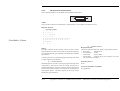
This 24-way input/output connector on the rear panel, which is labelled IEEE-488, is
directly compatible with the IEEE-488 and IEC-625 Interface Bus standards.
Pin Layout
Selection of Operating Line
Voltage
12
1
24
13
Pin Designations
Pin No. Name
1.
2.
3.
4.
5.
6.
Ensure that the POWER CABLE is
removed.
Insert a small screwdriver blade in the
narrow recess beneath the catch under the
fuse drawer; lever gently downwards until
the catch releases. Pull the drawer out to
reveal the grey voltage selector block.
Hook a small finger into the block in the
square recess in its base; pull to disengage
its contacts, and remove from the module
cavity.
Rotate the voltage selector board until the
desired voltage faces outward.
Ensure that the block is upright. Re-insert
the block firmly into its cavity in the
module.
Check the fuse if required (see paras 2.7.4),
then insert the fuse drawer into the module
and press until the catch is heard to click
into place.
Check that the desired voltage is visible in
the cutout in the fuse drawer.
1
2
3
4
5
6
7
8
9
10
11
12
13
14
15
16
17
18
19
20
21
22
23
24
DIO 1
DIO 2
DIO 3
DIO 4
EOI
DAV
NRFD
NDAC
IFC
SRQ
ATN
SHIELD
DIO 5
DIO 6
DIO 7
DIO 8
REN
GND 6
GND 7
GND 8
GND 9
GND 10
GND 11
0V_F
Description
Data Input Output Line 1
Data Input Output Line 2
Data Input Output Line 3
Data Input Output Line 4
End or Identify
Data Valid
Not ready for Data
Not Data Accepted
Interface Clear
Service Request
Attention
Screening on cable (connected to Safety Ground)
Data Input Output Line 5
Data Input Output Line 6
Data Input Output Line 7
Data Input Output Line 8
Remote Enable
Ground wire of twisted pair with DAV
Ground wire of twisted pair with NRFD
Ground wire of twisted pair with NDAC
Ground wire of twisted pair with IFC
Ground wire of twisted pair with SRQ
Ground wire of twisted pair with ATN
Logic Ground (Internally associated with Safety Ground)
Continued overleaf→
Section 2: Installing the Model 9500B
2-7
2.8
Connectors and Pin Designations (Contd.)
2.8.2
Parallel Port (Rear Panel)
2.8.3
This 25 way D-Type socket is located beneath the IEEE-488
connector on the rear panel. Its connections are similar to the 25way printer port on PCs, carrying control and data for an external
printer as designated in the table.
Pin Layout
13
PARALLEL PORT
25
1
2
3
4
5
6
7
8
9
10
DO1
DO2
DO3
DO4
DO5
DO6
DO7
DO8
ACKNLG_L
11
BUSY_H
12
13
14
P_END_H
SLCT_H
AUTO_FEED_L
15
ERROR_L
16
INIT_L
17
SLCT_IN_L
18-25
0V_F
_H ≡ Logic-1 active;
2-8
Pin Layout
SERIAL PORT
Pin Designations
9500B 9500B
9500B Description or
Pin No. Signal Name I/O Common Meaning
STROBE_L
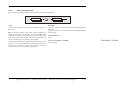
This 9-way D-Type socket is located to the left of the Parallel
port connector on the rear panel. Its connections are RS232compatible; carrying control and power supplies for, and receiving
data from, an external tracker ball.
14
Pin Designations
1
Serial Port (Rear Panel)
Output 1µs pulse to cause printer to read one byte
of data from data bus DO1 — DO8.
Output Data bit 1
Output Data bit 2
Output Data bit 3
Output Data bit 4
Output Data bit 5
Output Data bit 6
Output Data bit 7
Output Data bit 8
Input Pulse to indicate that the printer has
accepted a data byte, and is ready for more
data.
Input Printer is temporarily busy and cannot
receive data.
Input Printer is out of paper.
Input Printer is in on-line state, or connected.
Output Paper is automatically fed 1 line after printing.
This line is fixed _H (high) by the 9500B to
disable auto feed.
Input Printer is in 'Paper End', 'Off-line' or 'Error'
state.
Output Commands printer to reset to power-up
state, and in most printers to clear its print
buffer.
Output Commands some printers to accept data.
This line is fixed _L (low) by the 9500B.
Output Digital Common
_L ≡ Logic-Ø active.
Section 2: Installing the Model 9500B
Pin No.
Name
Description
1
2
3
4
5
6
7
8
9
--RXD0_L
TXD0_L
DTR0_H
0V_F
DSR0_H
RTS0_H
CTS0_H
---
Not used
Serial Data: Tracker Ball → 9500B
Serial Data: 9500B → Tracker Ball
Data Terminal Ready
Digital Common
Data Set Ready
Request to Send
Clear to Send
Not used
_H ≡ Logic-1 active;
_L ≡ Logic-Ø active.
2.9
2.8.4
Auxiliary Input (Rear Panel)
AUXILIARY
INPUT
≤ 40Vpk
This SMC connector is located at the upper center of the rear panel,
providing an internal, passive, relay switched route for a user's external
calibration signal, via any one of five output channels to an Active
Head's BNC or PC3.5 connector .
Internal controls are provided (via front-panel keys or via the IEEE-488
/ SCPI interface) to switch the signal between channels. For further
details see Section 4, para 4.15.5 and Section 6, para 6.6.5.17.
2.8.5
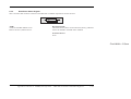
Ref Frequency Input (Rear Panel)
REF FREQUENCY
INPUT
Care of Microwave Connectors
It is necessary to observe certain basic precautions when using microwave
connectors, in order to achieve accurate and repeatable calibration and
measurement results. This will also help to extend connector life.
Good practice includes:
• When not in use, ensure that connectors are kept clean. This is best
done by using a plastic endcap. Avoid touching components whose
function is to make electrical contact.
• Visually inspect all connectors, looking for dents, scratches and
metal particles. Never use damaged connectors.
• Clean connectors properly, particularly connector threads and
dielectric faces. Try compressed air first, and if this is insufficient,
use isopropyl alcohol. Avoid spillage, and never use abrasives.
• When making connections, be careful to align connectors carefully,
avoiding bending forces. Always make the initial connection
lightly to avoid cross-threading, and use a correctly-set torque
wrench for final tightening.
≤ 5Vpk
50Ω
This BNC connector is located at the middle center of the rear panel,
providing an input for a signal of good frequency accuracy, for use as
a frequency reference in the 9500B.
Internal controls are provided (via front-panel keys in Configuration
mode) to select the signal as reference. For further details see Section
3, para 3.4.3.10.
2.8.6
Ref Frequency Output (Rear Panel)
REF FREQUENCY
OUTPUT
1V pk-pk nom
into 50Ω
This BNC connector is located at the lower center of the rear panel,
providing an output reference signal of the same frequency accuracy as
the 9500B.
Internal controls are provided (via front-panel keys in Configuration
mode) to select the signal as reference. For further details see Section
3, para 3.4.3.11.
Section 2: Installing the Model 9500B
2-9
This page deliberately left blank
This page intentionally left blank
BLANK PAGE (LEFT-HAND)
Section 3
Model 9500B Controls
3.1
About Section 3
3.1.1
Introduction
Section 3 is a detailed description of the 9500B operating controls;
starting with a general description of the front panel. The user
preferences 'Pref' key and screen is described, followed by a brief
description of Mode selection.
3.1.2
Section Contents
Section 3 is divided into the following sub-sections:
3.1
3.2
3.3
page
About Section 3
Introduction to the Front Panel
3.2.1 Local and Remote Operation .................................................. 3-2
3.2.1.1 Remote, Semi-Automatic and Manual Calibration
of UUT Oscilloscopes ............................................... 3-2
3.2.1.2 Use of Procedure Memory Cards ............................. 3-2
3.2.1.3 Manual and Remote Calibration of the 9500B Itself .. 3-2
3.2.1.4 General Arrangement of Front Panel Controls ......... 3-2
3.2.2 Front Panel Features .............................................................. 3-3
3.2.2.1 Liquid Crystal Display and Screen Keys ................... 3-3
3.2.2.2 'OSCILLOSCOPE CALIBRATOR' Panel .................. 3-3
3.2.2.3 Output Connections .................................................. 3-3
3.2.2.4 'Procedure' and 'Results' Memory Card Slots ........... 3-3
3.2.2.5 'Standby' Push-Button .............................................. 3-3
3.2.2.6 Power On/Off Switch ................................................ 3-3
3.2.3 Output Controls ....................................................................... 3-4
3.2.3.1 Front Panel Control Sets .......................................... 3-4
3.2.3.2 Entry to Manual Mode .............................................. 3-4
3.2.3.3 Manual Mode — Typical Menu Screen ..................... 3-4
3.2.3.4 Editing on the Screen ............................................... 3-4
Preferences
3.3.1 Pref Selection .......................................................................... 3-6
3.3.1.1 Pref Overview ........................................................... 3-6
3.3.1.2 Changing the Parameters ......................................... 3-6
3.3.1.3 Screen Contrast ........................................................ 3-6
3.3.1.4 Scope Mode Amplitude Steps ................................... 3-6
3.3.1.5 Scope Mode Time Steps ........................................... 3-6
3.3.1.6 Deviation Display ...................................................... 3-7
Descriptions assume 9500B/1100
3.4
page
Modes of Operation
3.4.1 Mode Selection ....................................................................... 3-8
3.4.1.1
Mode Overview ...................................................... 3-8
3.4.2 Passwords and Access ........................................................... 3-9
3.4.3 Configuration Mode ................................................................. 3-9
3.4.3.1
'MORE' Configuration ............................................ 3-9
3.4.3.2
'Ref Frequency' ...................................................... 3-10
3.4.3.3
'Safety voltage' ....................................................... 3-10
3.4.3.4
'Bus address' ......................................................... 3-10
3.4.3.5
'Printer' ................................................................... 3-11
3.4.3.6
'Power-up mode' .................................................... 3-11
3.4.3.7
'NEW PASSWORD' ............................................... 3-12
3.4.3.8
'CALIB Password' .................................................. 3-12
3.4.3.9
'CONFIG Password' .............................................. 3-12
3.4.3.10 'Ext ref in' ............................................................... 3-13
3.4.3.11 'Ext ref out' ............................................................. 3-13
3.4.3.12 'DATE TIME' .......................................................... 3-13
3.4.3.13 'HEAD CONFIG' .................................................... 3-14
3.4.3.14 'MORE' Configuration ............................................ 3-14
3.4.3.15 'Language' ............................................................. 3-14
3.4.3.16 'Border line' ............................................................ 3-14
3.4.3.17 'Results card' ......................................................... 3-15
3.4.3.18 'Engineers Notes' ................................................... 3-15
3.4.3.19 'Certificate' ............................................................. 3-16
3.4.3.20 'CERT STYLE' ....................................................... 3-16
3.4.3.21 'PAGE SETUP' ....................................................... 3-16
3.4.3.22 'Start page number' ................................................ 3-16
3.4.3.23 'Page length, header and footer sizes' .................. 3-17
3.4.3.24 'Pass indicator'........................................................ 3-17
3.4.3.25 'Appended message' ............................................. 3-17
3.4.3.26 'LAB DETAILS' ....................................................... 3-17
3.4.3.27 'LAB NAME' ........................................................... 3-17
3.4.3.28 Laboratory Temperature and Humidity .................. 3-17
3.4.3.29 'CLEAR USER LIST' .............................................. 3-18
3.4.3.30 '*IDN CONFIG' ....................................................... 3-18
3.4.3.31 'CAL Alarms' .......................................................... 3-18
Section 3: Model 9500B Controls: Modes of Operation
3-1
Final Width = 215mm
3.2
Introduction to the Front Panel
3.2.1
Local and Remote Operation
3.2.1.1
Remote, Semi-Automatic and Manual Calibration of UUT Oscilloscopes
The 9500B has been designed to present three main user interfaces for control of UUT calibration:
• Fully-automatic operation for UUT oscilloscopes which are remotely controllable on the IEEE-488 Instrumentation Control Interface,
employing IEEE-488.2/SCPI protocols. The 9500B also includes emulation modes which minimize the software effort required for
integration into existing calibration systems designed around Tektronix CG5011 and SG5030 calibrators. Refer to Section 6.
• Semi-automatic operation using procedure memory cards to drive the 9500B, with control of the subject UUT being implemented by a form
of the UUT manufacturer's procedure through a series of user prompts. Refer to Section 5.
• Manual operation from the front panel, again with control of the subject UUT being implemented by the UUT manufacturer's procedure. Refer
to Section 4.
3.2.1.2
Use of Procedure Memory Cards
This is a form of assisted (semi-automatic) calibration, in which a memory card for a specific UUT oscilloscope is inserted into PCMCIA SLOT 1.
Running Procedure Mode will generate instructions to the operator, while setting output values on the 9500B. The sequence of these instructions
and outputs, the output specifications and the pass/fail limits conform the UUT manufacturer's calibration procedure.
3.2.1.3
Manual and Remote Calibration of the 9500B Itself
The 9500B itself must periodically be verified or calibrated against suitable traceable standards. The calibration processes for the mainframe and
Active Heads are available manually, but to gain the advantages of simplicity and throughput provided by automated procedures, these process
commands are also available via the remote interface (IEEE-488.2/SCPI protocols - Section 6.). The 9500B communicates with programmable
standards under the direction of external Control Software.
3.2.1.4
General Arrangement of Front Panel Controls
The front panel is divided into three main areas:
Standby/Normal
Center: A 'Menu' and 'Output Display' LCD screen, with grouped soft keys.
Right: A control panel, used to select and adjust operational Functions and Modes, with two slots to accept memory cards.
Left: Output Connectors, used for connection of the active heads.
These features are described in the following paragraphs.
3-2
Section 3: Model 9500B Controls: Modes of Operation
Descriptions assume 9500B/1100
3.2.2
Front Panel Features
3.2.2.1
Liquid Crystal Display and Screen Keys
The 9500B communicates with the operator by presenting essential information on the LCD screen. For example: the output value generally
appears in large characters below the center of the screen, accompanied by its units. An operator can move through a series of menu screens,
choosing options from those presented on the screen.
Eleven soft keys ('screen' keys) are grouped below and to the right of the screen. These are labelled by characters or symbols representing menu
choices, which appear in reserved display areas on the screen next to the keys. Main functions are selected by buttons on the 'Oscilloscope
Calibrator' panel.
3.2.2.2
'OSCILLOSCOPE CALIBRATOR' Panel
This panel carries the main controls used to select the operational functions and modes of the calibrator:
a. Major Function keys are used mainly in Manual mode (Section 4) and Calibration mode (Section 10). They are arranged down the right
edge:
:
Waveform (select Square with direction, or ±DCV using screen keys).
:
Sinewave (select amplitudes and frequency using screen keys and cursor controls).
:
Edge (select polarity using screen keys).
:
Timing Markers (select Waveform and Frequency/Period using screen keys — including Line Frequency).
Aux
:
Auxiliary Functions (select Current, Composite Video, Linear Ramp, Overload Pulse, UUT Input Leakage Test, Auxiliary
Input, Channel Skew, and Load Resistance or Load Capacitance measurement using screen keys).
b. Mode Key, under the Function keys. The modes are: 'Procedure', 'Manual', 'Configuration', 'Calibration' and 'Test' (refer
to sub-section 3.4).
c. Preferences Key, the bottom key. The user-preferences provided are display adjustments of: 'Screen Contrast', 'Amplitude
step' factor sequence, 'Time step' factor sequence and Deviation/UUT Error toggle (refer to sub-section 3.3).
d. OUTPUT OFF and ON keys, with an 'ON' state indicator LED, in a separate column due to their importance.
e. Alpha-numeric keypad, used for various purposes, to be described later.
f. The
3.2.2.3
(Tab) key, Cursor keys and Spinwheel: These select and increment or decrement displayed quantities.
Output Connections
The ten output connectors are located on the left of the panel. Use of these connectors is described in Section 4.
3.2.2.4
PCMCIA SLOT 1 and PCMCIA SLOT 2
These slots are included mainly for Procedure mode (Section 5), although there are secondary uses.
3.2.2.5
'Standby' Push-Button
Pressing this button, in the bottom right corner of the front panel, will toggle between normal operation (LED green) and 'standby' (LED red).
The instrument will transfer automatically from normal operation to standby some 15 minutes after the most recent operation, then pressing the
button will immediately restore normal operation.
3.2.2.6
Power On/Off Switch
Line power to the 9500B is switched On and Off using a switch at the left of the instrument, on the rear panel. Up is On; Down is Off.
Descriptions assume 9500B/1100
Section 3: Model 9500B Controls: Modes of Operation
3-3
3.2.3
Output Controls
The aim of this discussion is to become familiar with the 9500B
interactive display, and the manipulation of front-panel controls.
We have chosen DC/Square as a typical function for manipulation (it is
also likely to be the most familiar to most new operators).
Full details of the DC/Square function are not given here, they appear
in Section 4 Subsection 4.5.
3.2.3.1
Front Panel Control Sets
We have already seen that there are two sets of front-panel controls
which manipulate the output configuration, but briefly, to establish a
base-line, here they are again:
Final Width = 215mm
1. Controls positioned in the right half of the front panel. They are:
a. Major Function keys, arranged in a column down the right
edge.
b. Moving left, the OUTPUT OFF and ON keys, arranged in a
separate column because of their importance.
c. Alpha-numeric Keypad.
d. Cursor Controls:
See paras 3.2.3.4.
2. Screen Soft Keys, around the display itself, are used to select subfunctions and individual parameters (identified in the areas used as
screen key labels).
Before we proceed, we need to identify the components present on a
typical menu screen. A representation of a DC/Square display in
Manual mode is given as Fig 3.2.1.
3.2.3.2
Entry to Manual Mode
This discussion is conducted in Manual mode, which you may not
recognize at present. Refer to paras 3.4.1. To enter MANUAL mode:
1. Press the front panel Mode key;
2. Press the MANUAL screen key beneath the display.
3-4
Section 3: Model 9500B Controls: Modes of Operation
3.2.3.3
Manual Mode — Typical Menu Screen
Ensure that the 9500B is installed and switched on as in Section 2. If,
after selecting Manual mode, the display does not correspond to Fig.
3.2.1, press the
key in the top right corner of the front panel.
Familiarize yourself with Fig. 3.2.1. This is the default version of
the menu screen which will appear when you enter DC/Square
function for the first time (unless the default has been changed in
Config Mode).
N.B. Contrast inversions of symbols and fields indicate those elements
which have been selected, 'Scope Mode' (1-2-5) only in this
case.
3.2.3.4
Editing on the Screen
We have already mentioned 'Scope Mode'. This is not a major mode of
the same importance as Manual mode, but identifies a specific means
of making selections or entering changes on the screen.
In all editing, the Tab key
is used to select the required variable for
adjustment.
There are two modes, selected by the right-most soft key on the bottom
row beneath the screen, which toggles between 'Direct' mode 15 2 1.Ø
and 'Scope' mode 15 2 1.Ø encompassing three main ways of adjusting
values presented on the screen:
1. Direct Mode 15 2 1.Ø
Once the
key has selected the required variable, two triangular
markers presented above and below a digit in the selected numeric
value form a cursor, and two methods of value adjustment are
available:
a. Digit Edit.
Cursor keys:
control the screen cursor to
and
select a digit for adjustment, then increments
and
decrements the digit selected by the
cursor.
Spinwheel:
Increments or decrements the selected digit, in
place of the
and
keys.
Descriptions assume 9500B/1100
b. Numeric-Entry Edit.
Key Pad:
Typing any character on the numeric keypad
will set up a 'box' beneath a smaller version of
the selected numeric value, and place the typed
character in the box. The right side key labels
change to give a choice of units.
Units:
After the new value has been typed on the
keypad, the required units can be chosen from
the right side soft keys. Pressing one of these
keys will cause the display to revert to the 'Digit
Edit' format, with the same numeric value
remaining selected by the two triangles.
'Enter':
The keypad 'Enter' (ø) key can be used instead
of one of the units keys to revert to 'Digit Edit'
format. In this case the 9500B firmware will
always impose the basic units (not multiples or
sub-multiples).
Further Use: Either Digit Edit or Numeric-Entry Edit can be
used for all selectable variables on the screen.
Selected SIGNAL
Channel
Function
Icon
'Barred'
Selection
Cursor
SIGNAL
TRIGGER
CH1
CH5
1 2
1.Ø
5
This mode differs from Direct Mode only in that adjustment of
many screen variables is constrained to a series of 'Stepped Values',
which run in a sequence of 1 : 2 : 5 factor steps (The 'Pref' facility,
described overleaf, can be used to change the factor sequence to
match certain oscilloscopes with 1 : 2 : 2.5 : 4 : 5 steps). Selecting
one of these variables places a 'barred' cursor above and below the
whole numeric value (shown in Fig 3.2.1), and only one method of
value adjustment is available:
Cursor keys:
and
are not used. Adjustment is
carried out using the
keys (or
and
spinwheel) to increment or decrement the whole
value through the pre-defined factor steps.
These forms of editing are also described in greater detail, with
illustrations, in Section 4, sub-section 4.4.
Final Width = 215mm
Expected Load
Impedances
Selected TRIGGER
Channel or
'No Trigger' State
Output
State
OFF
3. Scope Mode
Multiplies Selected
Value by 10
x 1Ø
5ØΩ
5ØΩ
Divides Selected
Value by 10
1Ø
5.ØØ mV/div x4
= 2Ø.ØØØ mVpk-pk
Deviation = ØØ.ØØ %
Toggles Deviation between
zero and previously set value
O/P Amplitude = 2Ø.ØØØ mVpk-pk
Frequency = 1.ØØØØ kHz
Numeric
Output
Values
Output
Value
Units
∆=Ø
TODAY'S DATE
TIME
WAVE
FORM
Soft key label
not used with
DC/Square
Default
Screen
These three soft key
labels not used with
the DC/Square
Default Screen
Accesses
Waveform
Menu
(Toggle)
Applies
Ground
Condition
(O/P On)
CHANNEL
SELECT
1 2
1.Ø
5
Accesses
Channel
Selection
Menu
Toggles
to Select
'Scope' or
'Direct Entry'
Mode
Screen
Key
Effects
Uses of all the right side
soft key labels are
dependent on the field
selected on the main part
of the screen
All bottom soft key labels
may be employed for
alternative or additional
selections
Fig. 3.2.1 Manual Mode — Startup Default Settings
Descriptions assume 9500B/1100
Section 3: Model 9500B Controls: Modes of Operation
3-5
3.3
Preferences
3.3.1
Pref Selection
The Pref key is highlighted in Fig. 3.3.1, below:
3.3.1.2
Changing the Parameters
The mechanism for adjusting parameters is known as 'Digit Edit'. A
Cursor of horizontal lines enclosing screen characters indicate the
parameter selected for adjustment. This can be moved from one
parameter to another using the
(Tab) key.
Once the cursor has been moved to the required parameter, the adjustment
(Down)
(Up) /
is carried out using either the spinwheel or the
cursor keys. The Left and Right cursor keys have no effect.
3.3.1.3
Final Width = 215mm
3.3.1.1
Fig. 3.3.1 'Pref' Key
Pref Overview
The Pref key sets up a special display which offers adjustment of four
parameters, shown in Fig. 3.3.2. This menu can be exited only by
pressing EXIT, or re-pressing the Pref key.
Preferences
Mode
Pref
Contrast
= 10
Amplitude step = 1-2-5
Time step
= 1-2-5
Deviation Display = Deviation
TODAY'S DATE
The front panel screen is viewable from a wide range of vertical and
horizontal angles. For best contrast at a fixed angular sight line in the
vertical plane, the 'Contrast' parameter on the screen can set the sight
line to one of twenty-seven different angles, represented by the numbers
1-27. The range from numbers 10-12 will provide good contrast from
head-on viewing positions.
To change the contrast:
1. Use the tab key to position the cursor on the contrast number.
2. Use the spinwheel or up/down cursor keys to adjust for your best
display contrast, by increasing or decreasing the contrast number.
3.3.1.4
Scope Mode Amplitude Steps
For most UUT oscilloscopes, amplitude sensitivity can be increased or
decreased at values which run in a sequence of 1 : 2 : 5 factor steps. The
Scope Mode 'Amplitude step' parameter can change the sequence to
match certain oscilloscopes with 1 : 2 : 2.5 : 4 : 5 factor steps.
To change the Amplitude steps parameter:
1. Use the tab key to position the cursor on the Amplitude steps
sequence.
2. Use the spinwheel or up/down cursor keys to toggle between
1—2—5 and 1—2—2.5—4—5 factor steps.
TIME
EXIT
Fig. 3.3.2 'Pref' Parameters
The Preference screen can be displayed in all modes and functions
without disturbing the function setup (except that under certain conditions
with OUTPUT ON, the output will be turned off).
Preference selections are non-volatile. Once a parameter has been set
up as required, it will be remembered by the 9500B through changes of
mode and function, also being restored after Power down / Power up.
3-6
Screen Contrast
Section 3: Model 9500B Controls: Modes of Operation
3.3.1.5
Scope Mode Time Steps
This operates on the same basis as Amplitude steps, but the result is a
change in output period (and frequency) in the chosen factor steps.
To change the Time steps parameter:
1. Use the tab key to position the cursor on the Time steps sequence.
2. Use the spinwheel or up/down cursor keys to toggle between
1—2—5 and 1—2—2.5—4—5 factor steps.
Descriptions assume 9500B/1100
3.3.1.6
Deviation Display
The deviation of an output signal amplitude from the factored output
step value is controllable, within ±11.2%, from the function screen. So
a signal of 1V DC can be adjusted from 0.8880V to 1.1120V using the
deviation control.
To extend the usefulness of this facility, the deviation display value can
be expressed as 'UUT Error'. This permits use of the deviation control
to adjust the 9500B output until the UUT oscilloscope presentation
itself shows the required value. The 9500B output value can be read off,
but in addition, the UUT's error is presented on the 9500B screen.
Note that both the UUT error and the deviation are expressed as a
percentage (ratios). This means that if the deviation has to be adjusted
to +10.00%, the UUT error is -9.091%. An example will show why:
Example of 'UUT Error'
1. Assume a 1V UUT nominal cal point.
2. 9500B set to 1V: UUT reading is low.
3. 9500B 'Deviation' increased until UUT reading is 1V nominal —
Deviation value is +10% and 9500B output is 1.1V.
4. A UUT reading of '1V' represents 1.1 x 1V, so UUT original reading
for 1V input was 1V ÷ 1.1 = 0.909091V.
5. The UUT Error is therefore 0.909091V - 1V = -0.09091V.
6. The UUT percentage Error is (0.09091V ÷ 1V) x 100%,
= -9.09091%
Final Width = 215mm
To change the Deviation parameter:
1. Use the tab key to position the cursor on the Deviation display
parameter.
2. Use the spinwheel or up/down cursor keys to toggle between
'Deviation' and 'UUT Error'.
Descriptions assume 9500B/1100
Section 3: Model 9500B Controls: Modes of Operation
3-7
3.4
Modes of Operation
3.4.1
Mode Selection
Mode Selection
The Mode key is highlighted in Fig. 3.4.1, below:
Select required mode using softkeys
Aux
Mode
Pref
TODAY'S DATE
TIME
PROC MANUAL CONFIG
CALIB
TEST
Fig. 3.4.2 Mode Selection Menu
Final Width = 215mm
Fig. 3.4.1 'Mode' Key
3.4.1.1
Mode Overview
The Mode key sets up a special menu display, offering selection from
five primary modes. This menu can be exited only by pressing one of
the five screen keys.
3-8
Section 3: Model 9500B Controls: Modes of Operation
Four of the modes are described in later sections, but because of its
wide-ranging effects, Configuration Mode is dealt with in this section.
The five modes are:
PROC
= Procedure Mode:
For calibration of a specific type of UUT, the sequence of 9500B output
selections is determined by a 'Procedure' memory card, placed in the
left-hand PCMCIA SLOT 1 beneath the panel outline. Results can be
printed, or recorded in a second 'Data' card, placed in the right-hand
PCMCIA SLOT 2. Refer to Section 5.
MANUAL = Manual Mode:
The output is selected and adjusted entirely from the front panel. Refer
to Section 4.
CONFIG = Configuration Mode:
On entry to Configuration mode, parameters are protected by password.
These include: Power-On default mode (Manual or Procedure modes);
Present Time and Date; Enable Printing; Reformat Printed Certificates;
etc. Refer to Sub-section 3.4.2.
CALIB
= Calibration Mode:
This mode is protected by switch and password. On entry to Calibration
mode, the operator can process the calibration of the 9500B itself.
Calibration can be controlled from the front panel, or via the IEEE-488
Interface. Refer to Section 10.
TEST
= Test Mode:
This mode permits an operator to initiate and interact with any of a series
of tests as follows: 'Base'; 'Heads'; 'All'; 'Fast' or 'Interface'. Refer to
Section 8.
Descriptions assume 9500B/1100
3.4.2
Passwords and
Access
1. All Configuration mode selections require
a password. When the 9500B is shipped
from new, the password requirement is
enabled to avoid unauthorized access.
2. It is recommended that both passwords be
changed, for security purposes, at the
earliest opportunity.
3. The shipment 'Configuration' password is
12321 (as typed on the front panel keypad
when the Password Entry screen for
Configuration mode is showing). It is
stated here to allow entry to Configuration
mode by personnel authorized by local
management, and permit subsequent
access to the means of altering the password
itself. The necessary process is detailed
later in this sub-section.
4. A second (different) password will be
required to allow entry to Calibration mode
as authorized by local management. The
shipment version of the Calibration mode
password is 2→3→5→7 (as typed on the
front panel keypad when the Password
Entry screen for Calibration mode is
showing) The necessary process for
changing this password is also detailed
later in this sub-section.
3.4.3
Configuration Mode
Configuration Mode is used to change the
settings of those parameters which have been
placed under user control.
N.B. A password is required for access to
change settings.
When changing configuration, start as follows:
1. Press the Mode key to obtain the 'Mode
Selection' menu screen.
2. Press the CONFIG screen key at the center
of the bottom row to progress into
'Configuration' mode. The 9500B will
transfer to the 'Configuration' menu screen:
Configuration
Ser. No. XXXXXX
Rev. XXX
Options : 1.1 GHz, Hi acc xtal, LN
Present Settings:
Ref frequency
Safety Voltage
Bus Address
Printer
Power-up mode
Ext ref in
Ext ref in
TODAY'S DATE
5Ø.ØØØ kHz
1ØØ.ØØ V
1
NONE
Manual
1Ø MHz
Disabled
TIME
MORE
3. The screen shows the present settings of
some of the parameters which can be
changed in Configuration mode.
4. The screen also indicates which hardware
Option 9500B/600, 9500B/1100 or 9500B/
3200 is fitted. These cannot be changed in
Configuration mode.
3.4.3.1
'MORE' Configuration
1. To gain access to alter Configuration mode
options, a password will be required. (Refer
to the arrangements made for 'shipment'
passwords described in Para 3.4.2)
2. The password requirement will be invoked
by pressing the MORE screen key on the
right of the bottom row. The 9500B will
transfer to the 'Password Entry' screen:
3. When you enter your password using the
Descriptions assume 9500B/1100
Password Entry
For Configuration
Enter password :
TODAY'S DATE
TIME
EXIT
alpha-numeric keypad, security icons will
appear on the screen as you type. Finally
press the ↵ key.
If the password is incorrect: an error
message will be given and the security
icons will be removed, enabling a new
attempt to enter the password.
The 'EXIT' screen key acts to escape, back
to the previous screen.
4. The correct password, followed by ↵, will
provide entry to the main 'Configuration'
menu screen, showing the present settings
of the parameters which now can be
changed using screen keys whose labels
appear on the display:
5. Pressing the 'MORE' key again will
Configuration
Ser. No. XXXXXX
Rev. XXX
Options : 1.1 GHz, Hi acc xtal, LN
Present Settings:
Ref frequency
Safety Voltage
Bus Address
Printer
Power-up mode
Ext ref in
Ext ref in
TODAY'S DATE
REF
FREQ
5Ø.ØØØ kHz
1ØØ.ØØ V
1
NONE
Manual
1Ø MHz
Disabled
TIME
VOLTAGE
LIMIT
DATE
TIME
HEAD
CONFIG
BUS
ADDRESS
PRINTER
POWER
UP MODE
NEW
PASSWRD
EXT REF
IN
EXT REF
OUT
MORE
provide entry to a second 'Configuration'
menu screen, showing the present settings
of other parameters. Refer to para 3.4.3.14.
Section 3: Model 9500B Controls: Modes of Operation
3-9
3.4.3.2
'Ref Frequency'
3.4.3.3
Use of Reference Frequency
The reference frequency is used mainly in
assessments of UUT oscilloscope bandwidth,
a commonly used frequency for this purpose
being 50kHz. In the 9500B, for ease of
operation in certain functions, the output can
be changed from the selected frequency to the
reference frequency and back by a simple
toggle switching action.
In the 9500B, the default reference frequency
is set at 50kHz, but users can change this in
Configuration mode to match the frequency
used in procedures for individual oscilloscopes.
1. For access to alter the reference frequency,
press the REF FREQ screen key at the
bottom left of the 'Present Settings' screen.
2. This transfers to a configuration screen
designed for changing the 'Ref Frequency'.
The default value is shown:
Configuration
5ØkHz
DEFAULT
The REFERENCE FREQUENCY
can be changed by using
direct editing only.
Ref =
TODAY'S DATE
5Ø.ØØ kHz
TIME
EXIT
High Voltage Warnings — Warning and
Interlock
In the interests of safety, to avoid electric
shock, the 9500B incorporates a high-voltage
warning and interlock system for both DC and
Square Voltage functions. The limit can be set
to any voltage from 10V to 110V. The default
warning threshold value (100V) can be changed
in Configuration mode. The active threshold
value is stored in non-volatile memory.
When the output is on in DC/Square or High
Edge function, the warning will sound when
the output voltage setting is raised to or above
the threshold value. The output will stay at its
previous value until the user confirms the new
voltage by re-pressing the OUTPUT ON button.
1. For access to allow the high voltage
warning threshold to be altered, press the
VOLTAGE LIMIT screen key on the
'Present Settings' screen.
2. This transfers to a configuration screen
designed for changing the 'Voltage Limit'.
The default value is shown:
Configuration
DEFAULT
100 V
The high voltage warning limit
can be changed by using direct
editing only.
The maximum value is 11ØV
3. Use Direct edit to set the required reference
frequency. After typing the value press the
↵ key on the keypad (the Direct edit 'V'
screen key in the right-hand column will
perform the same action).
4. The '50kHz DEFAULT' screen key on the
right can be used if 50kHz is required.
5. Press the EXIT screen key to return to the
'Present settings' menu screen. The new
reference frequency appears on the 'Present
Settings' list.
3-10
'Safety voltage'
Limit =
TODAY'S DATE
1ØØ.ØØ V
TIME
EXIT
3. Use Direct edit to set the required high
voltage warning limit. After typing the
value press the ↵ key on the keypad (the
Direct edit 'V' screen key in the right-hand
column will perform the same action).
4. The 'DEFAULT 100V' screen key on the
right can be used if 100V is the required
level.
Section 3: Model 9500B Controls: Modes of Operation
5. Press the EXIT screen key to return to the
'Present settings' menu screen. The new
high voltage threshold value appears on
the 'Present Settings' list.
Note: Out-of-Range Indication
The valid range of limit values is from 10V to
110V. When values outside this range are
entered, an error message will appear on the
screen, and the 'EXIT' screen key label will be
replaced by 'OK'. By pressing 'OK' the original
value is reinstated and the message disappears,
for a second attempt.
3.4.3.4
'Bus address'
Remote Operation via the IEEE-488
interface — Addressing the 9500B
When the 9500B is set for remote operation,
control is removed from the front panel and
given to an external controller.
Communication is set up between the 9500B
and its controller via the IEEE-488 bus,
connected into an interface within the 9500B.
Commands from the controller are addressed
to the 9500B using an address code, which can
be a number in the range 0-30. For the 9500B
to respond, this number must be matched by
the same number programmed into the 9500B
using the procedure given below.
Remote operation of the 9500B via the IEEE488 interface is described in Section 6.
N.B. The correct bus address is necessary to
use remote commands, but remote
operation is available only when the
instrument is in MANUAL or
CALIBRATION mode.
1. The 9500B IEEE-488 bus address can be
set to any number within the range 0 to 30.
For access from the 'Present Settings'
screen, press the BUS ADDRESS screen
key at the top right.
2. The 9500B transfers to the 'IEEE 488
ADDRESSES' screen:
Descriptions assume 9500B/1100
Configuration
IEEE 488 ADDRESSES
9500B address=
9500B
5ØØØ
SERIES
22
2nd address inactive
Configuration
The current printer type is
indicated by the highlight.
TIME
DESK JET
TODAY'S DATE
USER
DEFINED
TIME
EXIT
EXIT
3. Use numeric entry to set the required bus
address number. Type the number on the
keypad, then press the ↵ key.
4. Press EXIT to return to the 'Present Settings'
screen.
For second address (5000-series emulation),
refer to Section 6, Appendix F.
3.4.3.5
EPSON
BUBBLE
JET
Use the softkeys to select
another.
Change by direct edit only.
TODAY'S DATE
DISABLE
'Printer'
Printer Operation (Procedure Mode and
Test Mode only)
Using the Procedure mode print facility, the
9500B can deliver a printed certificate, whose
style is also determined in Configuration mode.
In Test mode, test results can also be printed —
in a pre-determined format. The results are
stored until the print command is given after
the test is over. The printer does not need to be
selected in Configuration mode, unless the
results print is required to conform to the
layout of a particular type of printer.
The printer is set up only when an attempt is
made to print, following two types of occasion:
a. printer type is changed in Config mode;
b. 9500B is powered on.
Printer Type Selection
1. For access to select and enable a particular
printer type (or one using the same
formatting), press the PRINTER screen
key on the 'Present Settings' screen.
2. This transfers to a 'Configuration' screen
to change 'The current printer type':
Descriptions assume 9500B/1100
3. Power-on default is DISABLE.
Use the screen keys to select the type of
printer on the interface, or to disable direct
printing.
4. EXIT returns to the 'Present Settings' menu
screen.
User Defined Printer Type
5. If the type of printer you are using does not
conform to one of those listed, press the
USER DEFINED screen key. This
transfers to a 'Configuration' screen
designed to enter the initialisation control
codes for your printer:
3.4.3.6
'Power-up mode'
Mode Selection at Power-on
Users can determine which mode will be
selected automatically at power-on, choosing
between Procedure mode and Manual mode.
The 9500B cannot be made to power-up in any
other mode.
To set the power-up default mode use the
procedure in the column on the right.
1. For access to change the default mode,
press the POWER UP MODE screen key
on the 'Present Settings' screen.
2. This transfers to a 'Configuration' screen
to change 'The default power-on mode':
Configuration
PROC
MANUAL
The default power-on mode is
indicated by the highlight.
Use the softkeys to select
another.
TODAY'S DATE
TIME
EXIT
Configuration
Enter the initialisation
control codes in decimal
and confirm with enter.
The current control code string is:
(string appears here
eg 27 116 1 18 15)
Enter a new control string:
TODAY'S DATE
TIME
EXIT
3. To change the default, press the required
screen key on the right.
4. Press EXIT to return to the 'Present Settings'
screen
The new default will be incorporated into the
list. Next time the line power is turned from
OFF to ON, the 9500B will power-up in the
selected mode.
6. Obtain the initialisation control codes from
your printer's operating manual. If
necessary, convert the codes to decimal.
Use the 9500B keypad to type the decimal
codes, separated by spaces (→): the new
string replaces the old. Press the ↵ key.
6. EXIT returns to the 'current printer type'
screen.
(continued overleaf)
Section 3: Model 9500B Controls: Modes of Operation
3-11
3.4.3.7
'NEW PASSWORD'
3.4.3.8
Changing the Passwords
Two passwords are required (they can be the
same or different):
• for entry to Configuration mode;
• to enter Calibration mode (for calibration
of the 9500B itself).
Refer to para 3.4.2. When the 9500B is shipped
from new, the password requirement is enabled
to avoid unauthorized access (refer to para
3.4.2). The shipment Configuration and
Calibration passwords allow initial access to
the two modes, but should be changed as soon
as entry has been gained into Configuration
mode.
The passwords are changed using the following:
To change either the CALIB or CONFIG
password
1. On the 'Present Settings' menu screen,
press the NEW PASSWORD screen key
on the right. This transfers to the 'Select
the Password' screen:
2. Select the password to be changed, via one
Configuration
CALIB
CONFIG
Select the password to be
changed using the softkeys.
TODAY'S DATE
TIME
EXIT
'CALIB' Password
3.4.3.9
'CONFIG' Password
To Change the Calibration Mode
Password
To Change the Configuration Mode
Password
1. On the 'Select the password' screen, press
the CALIB screen key on the right. This
transfers to the 'Enter new calib password'
screen:
1. On the 'Select the password' screen, press
the CONFIG screen key on the right. This
transfers to the 'Enter new config password'
screen:
Configuration
Configuration
Enter new calib password.
Enter new config password.
TODAY'S DATE
TIME
EXIT
(To cancel an attempt, press the EXIT key.
This will revert to the 'Select the password'
screen.)
2. Type the new password using the alphanumeric keyboard, and finish with ↵. The
9500B will ask for the password to be
entered again, to confirm it.
3. Retype the same password; finish with ↵.
If the second password is different from
the first, the 9500B will reject both, and the
process must be repeated. If both passwords
are the same, the 9500B will accept the
new password, and revert to the 'Select the
password' screen.
Note: The shipment version of the
'Calibration' password is 2→3→5→7.
TODAY'S DATE
TIME
EXIT
(To cancel an attempt, press the EXIT key.
This will revert to the 'Select the password'
screen.)
2. Type the new password using the alphanumeric keyboard, and finish with ↵. The
9500B will ask for the password to be
entered again, to confirm it.
3. Retype the same password; finish with ↵.
If the second password is different from
the first, the 9500B will reject both, and the
process must be repeated. If both passwords
are the same, the 9500B will accept the
new password, and revert to the 'Select the
password' screen.
Note: The shipment version of the
'Configuration' password is 12321.
of the two screen keys on the right.
3. The EXIT screen key reverts to the Present
Settings' screen.
3-12
Section 3: Model 9500B Controls: Modes of Operation
Descriptions assume 9500B/1100
3.4.3.10 'Ext ref in'
3.4.3.11 'Ext ref out'
Reference Frequency Input
A BNC connector on the 9500B rear panel
accepts reference frequency inputs from 1MHz
to 20MHz in 1MHz steps, from a TTL source.
1. On the 'Present Settings' screen, press the
EXT REF IN screen key to transfer to the
'Change the reference source' screen
(default shown).
2. To change the reference source, press the
required screen key on the right:
Reference Frequency Output
A BNC connector on the 9500B rear panel
provides a reference frequency output at either
1MHz or 10MHz, from a 50Ω source (VSWR
< 1.2 to 100MHz). This can use the 9500B
internal clock to enhance the frequency
accuracy of other devices.
1. On the 'Present Settings' screen, press the
EXT REF OUT screen key to transfer to
the current external reference output' screen
(default shown):
Configuration
Change the reference source
by using the softkeys.
Int.
Ref =
1Ø MHz
TODAY'S DATE
INT.
EXT.
The current external
reference output is
indicated by the highlight.
DISABLE
1 MHZ
10 MHZ
Use the softkeys to select
another.
Reference
LOCKED
TIME
TODAY'S DATE
EXIT
TIME
EXIT
3. When switched to 'EXT.', use the up/down
cursor control or spinwheel to inform the
9500B of the source frequency. Ensure
that the required source is connected and
operating.
Configuration
Change the reference source
by using the softkeys.
INT.
EXT.
Change the external reference
setting by using the cursor
keys or whirly wheel.
Ext.
Ref =
Configuration
1Ø MHz
TODAY'S DATE
Reference
UNLOCKED
TIME
EXIT
4. Press EXIT to return to the 'Present
Settings' screen.
The new external reference frequency is
available to enhance the 9500B internal clock.
Descriptions assume 9500B/1100
2. To change the external reference output,
press the required screen key on the right:
3. Press EXIT to return to the 'Present Settings'
screen.
The selected external reference frequency is
either disabled, or applied to the 'REF
FREQUENCY OUTPUT' BNC connector on
the rear panel.
3.4.3.12 'DATE TIME'
Date and Time Settings
A real-time clock, supported by an internal
battery, presents the date and time at the bottom
of many screens. It is also used to generate the
date to appear on direct-printing certificates in
Procedure mode. Users have access via
Configuration mode to correct the date and
time (for instance: to accommodate daylight
saving changes, and crossing time-zones).
1. Press the DATE TIME screen key on the
'Present Settings' screen, for access to allow
the date and time to be altered.
2. This transfers to a configuration screen
designed for changing the date and time.
Our representation shows the current date
from a previous setting:
Configuration
The selected date format is
indicated by the highlight.
Change the date by using
direct editing only.
D-M-Y
M-D-Y
Y-M-D
TOGGLE
DELIM
Ø8/Ø7/2001
TODAY'S DATE
TIME
CHANGE
DATE
EXIT
CHANGE
TIME
3. Press the appropriate right screen key to
set the required date format, and use the
keypad to correct the date, (using nonalphanumeric characters as delimiters),
followed by ↵. The new date will appear
with delimiters as set by the 'TOGGLE
DELIM' key, which merely switches
between 'slash' (/) and 'period' (.) only.
5. To correct the time, press the CHANGE
TIME screen key to transfer to the 'Change
the time' screen, then use the alpha-numeric
keypad to enter the present time:
Configuration
Change the time by using
direct editing only.
13-21
TODAY'S DATE
EXIT
TIME
CHANGE
DATE
CHANGE
TIME
6. Press the EXIT screen key to return to the
'Present settings' menu screen. The updated
corrected date and time, will appear
wherever they are used.
Section 3: Model 9500B Controls: Modes of Operation
3-13
3.4.3.13 'HEAD CONFIG'
3.4.3.15 'Language'
3.4.3.16 'Border line'
Information only
Pressing the 'HEAD CONFIG' key provides a
screen which indicates the type, serial no., cal
date and cal due date for each head fitted:
Language Considerations
The 9500B default language is English. It is
possible to change the language used in
Procedure mode, but not in any of the other
modes.
For Procedure mode the language of the
introductory screens can be changed (these are
stored within the 9500B itself).
The language used in a procedure card is
determined and registered on the card, within
the procedure header, at the time that the
procedure is created (Portocal II can perform
this function). When the procedure card is
being used in the Model 9500B, the language
cannot be changed.
Test Point Specifications — 'Borderline'
Reporting
For users who wish to know when a UUT is
drifting towards the limits of (while still within)
the manufacturer's specification, it is useful to
provide some 'borderline' indication. This can
be expressed as a percentage of the
manufacturer's specification for each test point,
beyond which the indication will be given.
In the figure, the pass, borderline and fail
regions of the specification tolerance are
indicated at the test point.
Configuration
Type
1 9510
S/N
XXXX
2 9510
XXXX
XX/XX/XXXX
XX/XX/XXXX
3
Head
ØØ/ØØ/ØØØØ
ØØ/ØØ/ØØØØ
4 9510 UNDEFINED
ØØ/ØØ/ØØØØ
ØØ/ØØ/ØØØØ
5
ØØ/ØØ/ØØØØ
ØØ/ØØ/ØØØØ
No
No
Cal Date
XX/XX/XXXX
Head
TODAY'S DATE
Due Date
XX/XX/XXXX
TIME
EXIT
Head calibration stores head details and
calibration corrections, specific to that head,
regardless of the base unit to which it is fitted.
The above screen presents the stored details
derived from the fitted heads.
3.4.3.14 'MORE' Configuration
After exiting to the 'Present Settings' screen,
pressing the 'MORE' key will provide entry to
a second 'Configuration' menu screen, showing
the present settings of other parameters
(generally associated with Procedure mode)
which can be changed using screen keys whose
new labels appear on the display:
Configuration
Ser. No. XXXXXX
Options : 1.1 GHz
Rev. XXX
Normal xtal
Present Settings:
Language
Border line
Results card
Engineers Notes
Certificate
TODAY'S DATE
English
7Ø.ØØ
Disabled
Disabled
Style 1
TIME
SELECT
LANG
BORDER
LINE
RESULTS
CARD
ENG
NOTES
CERT
DETAILS
CLEAR
USER
LIST
EXIT
The 'EXIT' screen key acts to escape, back to
the first Configuration menu screen.
If it desired to revert to the Mode Selection
display, press the front panel 'Mode' key.
3-14
This facility allows users to alter the language
used in the introductory screens of Procedure
mode:
Configuration
The current language is
indicated by the highlight.
Use the softkeys to select
another.
ENGLISH
GERMAN
SPANISH
TIME
EXIT
1. On the 'Present Settings' screen, to transfer
to the 'Current language' screen, press the
SELECT LANG screen key:
2. To change the Procedure mode language,
press the required language screen key on
the right.
3. Press EXIT to return to the second 'Present
Settings' menu screen.
The new language will be used the next time
that Procedure mode is entered.
Section 3: Model 9500B Controls: Modes of Operation
Borderline
Percentage
Nominal Test
Point Value
Borderline
Percentage
Lower 100%
Spec Limit
FRENCH
ITALIAN
TODAY'S DATE
Upper 100%
Spec Limit
UUT
Indicated
Value
Actual UUT
Input Value
Actual Test
Point Value
9500 Indicates 'Fail'
9500 Indicates 'Borderline'
9500 Indicates 'Pass'
When in Procedure mode, the direct-printing
certificate (Style 1), and the data on the 'Results'
card, will report 'Borderline' test results. Users
have access via Configuration mode to set the
percentage for borderline reporting.
1. For access to allow the borderline reporting
threshold to be altered, press the BORDER
LINE screen key on the 'Present Settings'
screen. This transfers to a configuration
screen designed for changing the threshold
(default value shown):
Descriptions assume 9500B/1100
Configuration
The percentage of UUT
specification tolerance
beyond which a "border line"
is reported can be adjusted
by using direct editing only.
Border line
TODAY'S DATE
=
7Ø.ØØ
TIME
EXIT
2. Use Direct edit to set the required
percentage of specification tolerance.
Results which lie between this percentage
and 100% of tolerance will be reported as
'Border line'.
3. Press the EXIT screen key to return to the
second 'Present settings' menu screen.
Subsequently, during each verification in
Procedure mode, the 9500B will detect its own
slewed output and place the UUT measurement
error into the 'Pass', 'Border line' or 'Fail'
category. When a (Style 1) certificate is printed,
and on any active results card, each test point
will indicate a 'Pass', 'Borderline' or 'Fail' result.
3.4.3.17 'Results card'
Formatting Results Memory Cards
(Procedure Mode only)
In Procedure mode, the 9500B can deliver the
results of a 'Calibrate' or 'Verify' procedure to
a memory card inserted into PCMCIA SLOT 2
in the front panel (refer to Section 5 of this
Handbook). Note that only SRAM cards can
be used in the PCMCIA SLOT 2 drive.
New SRAM cards must first be formatted for
the purpose. This can be carried out in Test
mode, as part of the 'Card Slot Test' procedure
(refer to Section 8), or within Portocal II
software.
Descriptions assume 9500B/1100
Caution!
During the formatting process, the Card Slot
Test over-writes all data stored on the card in
the slot, and sets up a new 'Results card header'.
Note:
It is not necessary to re-format a used card,
with results already stored, for it to accept new
data. New results data from Procedure mode
runs will be concatenated with existing data
until the card memory is full. Erasure of card
contents should be done using Portocal II.
1. For access to enable Procedure mode results
to be downloaded to a SRAM memory
card in the front panel PCMCIA SLOT 2,
press the RESULTS CARD screen key on
the 'Present Settings' screen.
2. The 'RESULTS CARD' screen key
transfers to 'The result card requirement'
menu screen.
The power-on default is DISABLE.
Configuration
DISABLE
ENABLE
The result card requirement is
indicated by the highlight.
Use the softkeys to select
another.
TODAY'S DATE
3.4.3.18 'Engineers Notes'
Engineer's Notes
When a certificate is being prepared in
Procedure mode, sometimes it will be desirable
to insert additional information about special
conditions, pertinent to the procedure which
was carried out.
For instance: if the procedure was performed
on a plug-in module of an oscilloscope, it may
be desired to add the serial number of the
oscilloscope mainframe, as well as the module's
serial number.
If, in CONFIG mode, the 'Engineers Notes' are
enabled, then an extra field will be added to the
certificate entitled 'Additional Notes' in which
any engineer's information can be entered. It
will appear between the 'Calibration Standard'
and 'Measurement Type' blocks.
The additional notes can be added on a screen
which will be shown in Procedure mode when
'Engineers Notes' are enabled.
To Enable Engineers Notes
1. On the second 'Present Settings' menu
screen, press the ENG NOTES screen key
on the right. This transfers to the 'Eng
notes requirement' screen:
Configuration
TIME
EXIT
3. To enable or disable the facility, press the
required screen key on the right of the
screen. If enabled without a results card
inserted in PCMCIA SLOT 2, the selected
procedure will not run.
4. EXIT returns to the second 'Present
Settings' menu screen.
DISABLE
ENABLE
The eng notes requirement is
indicated by the highlight.
Use the softkeys to select
another.
TODAY'S DATE
TIME
EXIT
2. Press the ENABLE screen key on the
right. The DISABLE key reverses the
process.
3. The EXIT screen key reverts to the second
'Present Settings' screen.
Section 3: Model 9500B Controls: Modes of Operation
3-15
3.4.3.19 'Certificate'
Results Certificates
In Procedure mode, three styles of printed
certificate are available:
Style 1
This provides full information about each point
tested, including applied and target values,
spec limits and UUT error, % error pass/fail
and test uncertainty ratio between 9500B and
UUT.
Style 2
This is a shorter form of certificate, showing
only the applied and target values, and the
9500B absolute uncertainty.
Style 3
This certificate is similar to Style 1, and has
been added to accommodate the wider spec
limits encountered during oscilloscope
calibration, expressed in percentages rather
than ppm.
Users are given the facility, in Configuration
mode, to change the style of certificate to be
printed.
1. For access to allow the certificate
formatting to be altered, press the CERT
DETAILS screen key on the second
'Present Settings' screen.
2. This transfers to what we shall refer to as
a 'CERT DETAILS' screen:
Configuration
Present Settings:
Certificate
Start page number
Page length
Pass indicator
Appended message
TODAY'S DATE
Style 1
1
66
ON
3. The 'CERT DETAILS' screen allows users
to design a certificate by adjusting or
selecting characteristics via screen keys
on the right (refer to paras 3.4.3.20 to
3.4.3.28).
4. The EXIT screen key reverts to the second
'Present Settings' screen.
1. For access to select the certificate style,
press the CERT STYLE screen key on the
'CERT DETAILS' screen. This transfers
to 'The certificate type' screen, which allows
the style of certificate to be selected:
Configuration
The certificate type is
indicated by the highlight.
STYLE 2
STYLE 3
Use the softkeys to select
another.
TODAY'S DATE
1
66
Ø
1
PAGE
LENGTH
HEADER
SIZE
FOOTER
SIZE
TIME
TIME
PAGE SETUP Screen Layout
2. Press the key on the right which describes
the attribute to be changed.
3. The EXIT screen key to revert to the
CERT DETAILS screen.
3.4.3.22 'Start page number'
1. To change the certificate start page number,
press the START PAGE screen key on the
'PAGE SETUP' screen. This transfers to
the 'Current start page' screen:
Configuration
EXIT
The current start page is
2. Press the key on the right which represents
the required style of certificate.
3. Press the EXIT screen key to revert to the
CERT DETAILS screen.
1. To set up the certificate page, press the
PAGE SETUP screen key on the 'CERT
DETAILS' screen. This transfers to what
we shall refer to as a 'PAGE SETUP'
screen, which allows users to design the
certificate page, using the keys on the
right:
EXIT
CERT DETAILS Screen Layout
3-16
STYLE 1
3.4.3.21 'PAGE SETUP'
TIME
Start page number
Page length
Header size
Footer size
START
PAGE
EXIT
PAGE
SETUP
PASS
INDIC
LAB
DETAILS
Present Settings:
TODAY'S DATE
3.4.3.20 'CERT STYLE'
CERT
STYLE
APPEND
MESSAGE
Configuration
Section 3: Model 9500B Controls: Modes of Operation
1
Enter a new page :
TODAY'S DATE
TIME
EXIT
2. Use Direct edit to enter the new start page
number.
3. Press the ↵ screen key to confirm the new
page number and return to the 'PAGE
SETUP' menu screen. The new page
number will appear on the 'Present settings'
list.
4. The EXIT screen key reverts to the PAGE
SETUP screen without changing the start
page number.
Descriptions assume 9500B/1100
3.4.3.23 Page length, header and
footer sizes
'Page length', 'Header size' and 'Footer size' are
changed by similar operations as for the 'Start
page number' change. No further explanation
is necessary.
After all the page setup characteristics are
satisfactory, press EXIT on the 'PAGE SETUP'
screen to return to the 'CERT DETAILS' screen.
3.4.3.24 'Pass indicator'
On the 'CERT DETAILS' screen, the 'PASS
INDIC' soft key acts as a toggle to turn the pass
indicator facility off and on. There is no
transfer to another screen, The state of the pass
indicator on the 'CERT DETAILS' screen
merely toggles between off and on as the
facility is altered.
3.4.3.25 'Appended message'
Message required for the Certificate
For the printed results certificates, users may
wish to add a descriptive message.
1. To access the message screen, press the
APPEND MESSAGE screen key on the
'CERT DETAILS' screen. This transfers
to the 'Current appended message' screen:
2. Use Direct edit to enter the new message.
Configuration
The current appended message is:
(The current message
appears in this space)
Enter a new message:
TODAY'S DATE
TIME
EXIT
Descriptions assume 9500B/1100
3. Press the ↵ screen key to return to the
'CERT DETAILS' screen. The message
appears on the 'Present settings' list.
4. The EXIT screen key reverts to the CERT
DETAILS screen without changing the
appended message.
Laboratory Details required for the
Certificate
For the printed results certificates, it is required
to enter details of the laboratory at which the
results were obtained.
Users should enter the name, temperature and
relative humidity of their laboratory for the
printed certificates.
1. To set up the Laboratory details, press the
LAB DETAILS screen key on the 'CERT
DETAILS' screen.
This transfers to what we shall refer to as
a 'LAB DETAILS' screen:
2. The lab name, temperature and humidity
Present Settings:
Lab name
Lab temp.
Lab humid.
TODAY'S DATE
Fluke L...
23°C ±5°C
40% ±10%
1. To enter the Laboratory name, press the
LAB NAME screen key on the 'LAB
DETAILS' screen. This transfers to the
'Current lab name' screen:
Configuration
3.4.3.26 'LAB DETAILS'
Configuration
3.4.3.27 'LAB NAME'
LAB
NAME
LAB
TEMP
LAB
HUMID
TIME
EXIT
LAB DETAILS Screen Layout
The current lab name is:
(The current name
appears in this space)
Enter a new name:
TODAY'S DATE
TIME
EXIT
2. Use Direct edit to enter the new laboratory
name.
3. Press the ↵ screen key to return to the 'LAB
DETAILS' screen: The new lab name will
appear on the 'Present settings' list.
4. The EXIT screen key reverts to the LAB
DETAILS screen without changing the
lab name.
3.4.3.28 Laboratory Temperature
and Humidity
'Lab temp' and 'Lab humid' are changed by
similar operations as for the 'Lab name' change.
No further explanation is necessary.
After all the laboratory details are satisfactory,
press EXIT on the 'LAB DETAILS' screen to
return to the 'CERT DETAILS' screen.
can be entered via the three screen keys on
the right.
3. The EXIT key reverts to the CERT
DETAILS screen.
Section 3: Model 9500B Controls: Modes of Operation
3-17
3.4.3.29 'CLEAR USER LIST'
Sec 3.4.3.30 *IDN? CONFIG
Sec 3.4.3.31 `CAL Alarms`
Procedure Mode User List
A list of users is presented on the opening
menu screen of Procedure mode, where the
user's name can be selected to appear on the
certificate. New names can be added to the
screen at the same time.
Names cannot be removed from the list without
knowing the Config mode password, which
must be used to access the 'Clear user list'
facility.
To retain compatibility with software
applications that depend upon instrument
response to the IEEE 488.2 common command
*IDN? it may be necessary to configure your
“Fluke 9500B” to respond as a previous model
“9500” from a previous manufacturer E.g.
“Wavetek”.
The default setting for calibration alarms is
enabled. This configuration allows these
alarms to be disabled.
1. For access to allow the Procedure mode
user list to be cleared, press the CLEAR
USER LIST screen key on the second
'Present Settings' screen. This transfers to
the confirmation screen:
Final Width = 215mm
Configuration
C F BARNES
F J BLOGGS
J K FLIPFLOP
1. On the second “Present Settings” menu
screen, press the IDN screen key on the
bottom row of Softkeys. This transfers to
the “*IDN? Config” screen:
1. On the second “Present Settings” menu
screen, press the CAL Alarm key on the
bottom row of Softkeys. This transfers to
the “CAL Alarm” screen:
SELECT
Configuration
Ser. No. XXXXXX
LANG
BORDER
Rev. XXX
Options : 3.2 GHz
LINE
Hi acc xtal
RESULTS
Present Settings:
SELECT
Configuration
Ser. No. XXXXXX
LANG
BORDER
Rev. XXX
Options : 3.2 GHz
LINE
Hi acc xtal
Language
English
Border line
7
Results card
Disabled
Engineers Notes
Disabled
Certificate
Style 1
ENG
Ø. ØØ
DETAILS
CLEAR
USER
LIST
CARD
Language
English
Border line
7
Results card
Disabled
Engineers Notes
Disabled
Certificate
Style 1
TODAY'S DATE
TIME
ENG
Ø. ØØ
NOTES
CAL
ALARM
*IDN?
CONFIG
DETAILS
CLEAR
USER
LIST
CAL
ALARM
EXIT
CERT
TIME
EXIT
NOTES
CERT
RESULTS
Present Settings:
TODAY'S DATE
CARD
*IDN?
CONFIG
Configuration
FLUKE
ENABLE
The ‘Cal Due’ alarm state is
indicated by the highlight.
Press OK to clear list
TODAY'S DATE
EXIT
Configuration
TIME
OK
FLUKE
USE ALT
MANUF
Use the softkeys to select
9500B
another.
The current *IDN? response is
3. OK removes all names from the list and
returns to the second 'Present Settings'
menu screen.
4. EXIT returns to the second 'Present
Settings' menu screen without removing
the names.
TODAY'S DATE
indicated by the highlight.
TODAY'S DATE
9500B
TIME
9500
EXIT
Use the softkeys to select
another.
TIME
9500
2. The EXIT screen key reverts to the second
“Present Settings” menu screen.
EXIT
2. The EXIT screen key reverts to the second
“Present Settings” menu screen.
3-18
Section 3: Model 9500B Controls: Modes of Operation
Descriptions assume 9500B/1100
Section 4
4.1
Using the Model 9500B — Manual Mode
About Section 4
Section 4 is divided into the following sub-sections:
page
4.1 About Section 4
4.2 Interconnections
4.2.1 Introduction ................................................ 4.2-1
4.2.2 Active Head Technology ™ ......................... 4.2-1
4.2.3 AUX IN ........................................................ 4.2-2
4.2.4 REF FREQUENCY INPUT ............................... 4.2-2
4.2.5 REF FREQUENCY OUTPUT ............................ 4.2-2
4.3 Manual Mode - Function Selection
4.3.1 Introduction ................................................ 4.3-1
4.3.2 Selection of Manual Mode ........................... 4.3-1
4.3.3 Front Panel Function Keys ........................... 4.3-1
4.4 Edit Facilities
4.4.1 Introduction ................................................ 4.4-1
4.4.2 Direct Mode ................................................ 4.4-1
4.4.3 Scope Mode ............................................... 4.4-4
4.5 DC/Square Function
4.5.1 Introduction ................................................ 4.5-1
4.5.2 Default Settings .......................................... 4.5-1
4.5.3 Menu Selections ......................................... 4.5-1
4.5.4 DC/Square Operation .................................. 4.5-4
4.5.5 Square Operation ........................................ 4.5-4
4.5.6 Using the 9500B Square Function to Calibrate the
Amplitude Response of a UUT Oscilloscope ... 4.5-6
4.5.7 DC Operation .............................................. 4.5-8
4.5.8 Using the 9500B DC Function to Calibrate the
Amplitude Response of a UUT Oscilloscope ... 4.5-9
4.6 Sine Function
4.6.1 Introduction ................................................ 4.6-1
4.6.2 Default Settings .......................................... 4.6-1
4.6.3 Menu Selections ......................................... 4.6-1
4.6.4 Sinewave Operation .................................... 4.6-2
4.6.5 Dual Channel Operation ............................... 4.6-4
4.6.6 Using the 9500B Levelled Sine Function
to Calibrate the Flatness/Bandwidth Response
of a UUT Oscilloscope .................................. 4.6-5
4.7 Edge Function
4.7.1 Introduction ................................................ 4.7-1
4.7.2 Default Settings .......................................... 4.7-1
4.7.3 Menu Selections ......................................... 4.7-1
4.7.4 Edge Function Operation .............................. 4.7-2
4.7.5 Using Active Head Models 9510/9520/9530 4.7-3
4.7.6 Using the 9500B Edge Function to Calibrate the
Pulse Response of a UUT Oscilloscope ......... 4.7-4
Descriptions assume 9500B/1100
page
4.8 Time Markers Function
4.8.1 Introduction ................................................ 4.8-1
4.8.2 Default Settings .......................................... 4.8-1
4.8.3 Menu Selections ......................................... 4.8-1
4.8.4 Time Markers Operation .............................. 4.8-2
4.8.5 Using the 9500B Time Markers Function to
Calibrate the Time Base of a UUT
Oscilloscope ............................................... 4.8-4
page
4.13 Overload Pulse Function
4.13.1 Introduction .............................................. 4.13-1
4.13.2 Overload Protection Test ............................ 4.13-1
4.13.3 Default Settings ........................................ 4.13-1
4.13.4 Menu Selections ....................................... 4.13-1
4.13.5 Overload Pulse Operation .......................... 4.13-1
4.13.6 Using the 9500B to Test the Overload Response
of a UUT Oscilloscope ................................ 4.13-2
4.9 Auxiliary Functions
4.9.1 Introduction ................................................ 4.9-1
4.9.2 Selection of Auxiliary Functions .................... 4.9-1
4.14 Zero Skew Function
4.14.1 Introduction .............................................. 4.14-1
4.14.2 Default Settings ........................................ 4.14-1
4.14.3 Menu Selections ....................................... 4.14-1
4.14.4 Zero Skew Operation ................................. 4.14-2
4.14.5 Measurement of UUT Oscilloscope
Channel Skew ........................................... 4.14-3
4.10 Current Function
4.10.1 Introduction .............................................. 4.10-1
4.10.2 Current Probe Accessory ........................... 4.10-1
4.10.3 Default Settings ........................................ 4.10-1
4.10.4 Menu Selections ....................................... 4.10-2
4.10.5 Current Operation ..................................... 4.10-2
4.10.6 Square Operation ...................................... 4.10-3
4.10.7 Using the 9500B Current (Square) Function to
Calibrate the Pulse Response of a
UUT Oscilloscope Current Probe ................. 4.10-4
4.10.8 DCI Operation ........................................... 4.10-5
4.10.9 Using the 9500B DCI Function to Calibrate the
Amplitude Response of a
UUT Oscilloscope Current Probe ................. 4.10-6
4.11 Composite Video Function
4.11.1 Introduction .............................................. 4.11-1
4.11.2 Signals and Triggers .................................. 4.11-1
4.11.3 Default Settings ........................................ 4.11-1
4.11.4 Menu Selections ....................................... 4.11-1
4.11.5 Composite Video Function Operation .......... 4.11-2
4.11.6 Using the Composite Video Function
to Calibrate Video Trigger Sensitivity
of a UUT Oscilloscope ................................ 4.11-2
4.12 Linear Ramp Function
4.12.1 Introduction .............................................. 4.12-1
4.12.2 Default Settings ........................................ 4.12-1
4.12.3 Menu Selections ....................................... 4.12-1
4.12.4 Linear Ramp Operation .............................. 4.12-1
4.12.5 Using the 9500B Linear Ramp Function for
Error Code Detection and
Trigger Level Marker Checks ..................... 4.12-2
4.15 Auxiliary Input
4.15.1 Introduction .............................................. 4.15-1
4.15.2 Automated Routing .................................... 4.15-1
4.15.3 Default Settings ........................................ 4.15-1
4.15.4 Menu Selections ....................................... 4.15-1
4.15.5 Auxiliary Input Operation ............................ 4.15-1
4.15.6 Using the 9500B for Automated Routing of
User-Specific Calibration Signals to
UUT Oscilloscope Input Channels ............... 4.15-2
4.16 Load Resistance and Capacitance Measurement
4.16.1 Introduction .............................................. 4.16-1
4.16.2 Measurement Method ............................... 4.16-1
4.16.3 Default Settings ........................................ 4.16-1
4.16.4 Menu Selections ....................................... 4.16-1
4.16.5 Measurement Operation ............................ 4.16-1
4.16.6 Use the 9500B to Measure Load Resistance
or Load Capacitance ................................. 4.16-2
4.17 Input Leakage Function
4.17.1 Introduction .............................................. 4.17-1
4.17.2 Input Leakage Test .................................... 4.17-1
4.17.3 Default Settings ........................................ 4.17-1
4.17.4 Menu Selections ....................................... 4.17-1
4.17.5 Input Leakage Operation ............................ 4.17-1
4.17.6 Using the 9500B to Test the Input Leakage Current
of a UUT Oscilloscope ................................ 4.17-2
4.18 Pulse Width Function
4.18.1 Introduction .............................................. 4.18-1
4.18.2 Trigger Qualification Timer Tests ................ 4.18-1
4.18.3 Default Settings ........................................ 4.18-1
4.18.4 Menu Selections ....................................... 4.18-1
4.18.5 Pulse Width Operations ............................. 4.18-1
Section 4: Using the Model 9500B — Contents
4.1-1
Final Width = 215mm
This
This page
page deliberately
deliberately left
left blank
blank
BLANK PAGE (LEFT-HAND)
4.2
Interconnections
4.2.1
Introduction
This sub-section deals with the Active Head
Technology™ used to connect the 9500B to a
UUT oscilloscope, and rear-panel signal inputs
and outputs. Section 4.2 is divided into the
following sub-sections:
page
4.2.1 Introduction
4.2-1
4.2.2 Active Head Technology ™
4.2-1
4.2.2.1 Connections to the 9500B
and UUT Oscilloscope .................................... 4.2-1
4.2.2.2 Head Module Signal Processing .................... 4.2-1
4.2.3 AUX IN (Rear Panel)
4.2-2
4.2.4 REF FREQUENCY INPUT
4.2-2
4.2.5 REF FREQUENCY OUTPUT
4.2-2
4.2.6 Single and Multiple Channel Outputs
4.2-2
4.2.6.1 Single-Channel Variants ................................. 4.2-2
4.2.6.2 Option 5 ......................................................... 4.2-2
4.2.2
Active Head Technology
The main function of a head is to route the
9500B's output to the UUT oscilloscope input
channel without intervening cables that could
degrade the signal.
Each head contains output circuitry that
generates and supports the transmission of
pulses of very short rise and fall times with low
distortion, and amplitude variable from ±5mV
to ±3V, and good 50Ω matching. This is
achieved by the use of low-loss substrate
dielectrics, with wide-band components,
attenuators and relays. The heads also perform
the function of sinewave levelling.
Available head modules include:
• Model 9510 — 1.1GHz Output Module
with 500ps pulse edge capability.
• Model 9530 — 3.2GHz Output Module
with 150ps and 500ps pulse edge capability.
• Model 9550 — Output Module with 25ps
pulse edge capability only.
• Model 9560 — 6.4GHz Output Module
with 70ps pulse edge capability.
Electrical specifications apart, modules are
interchangeable. The 9500B accepts any mix
of types, up to five modules.
Descriptions assume 9500B/1100
4.2.2.1
Connections to the 9500B
and UUT Oscilloscope
Two connections are used for each head. An
18-way connector and cable provides power
supplies, control and sense signals, whereas a
separate coaxial connector and cable carries
the signal or clock. The output signal is
delivered directly to the UUT oscilloscope's
input channel through the single BNC or
PC3.5 connection.
Caution:
The ! symbol, shown on the 9500B front
panel and heads, draws attention to information
contained in this handbook regarding maximum
output voltages and currents.
For details, refer to Section 7: Specifications.
4.2.2.2
Head Signal Processing
Signal processing in the head modules can be
summarized by considering the 9500B
functions:
a.
DC/Square . The signal is routed
directly via switched attenuators to the
output BNC or PC3.5 socket. Sensing
from the output is passed back to the
mainframe, effectively providing a 4-wire
delivery.
Sine. The sinewave at its final
b.
frequency is passed through the input SMA
coaxial cable. Sinewave amplitude is set
in the mainframe, but sensing for sinewave
levelling takes place in the head itself,
returning the levelling control signal to the
mainframe. The levelled signal is routed
via attenuators to the output BNC or PC3.5
socket.
c.
Edge. Pulse levels and timing
originate in the mainframe and pass to the
head for control of the edge generating
circuitry. Pulses with 500ps edge are routed
via the LF/DC attenuators to the output
BNC or PC3.5 socket (Models 9510/9530).
Special attenuators in Model 9530/9560
are used for the 150ps or 70ps edge pulses.
Markers. Marker types:
Square/Sine,
Pulses or
Narrow Triangle waveform), timing
and levels originate in the mainframe and
pass directly via switched attenuators to
the output BNC or PC3.5 socket. Line
frequency markers are also included.
e. Aux.
i.
DC/Square Current Source.
Current outputs between 100µA and
100mA are derived from the DC/Square
voltage source via an external BNC current
loop accessory (50Ω load to 9500B output).
The output calibrates current probes.
NB. Not compatible with 9550 or 9560.
ii.
Composite Video. Video voltage
outputs are passed directly via the output
BNC or PC3.5 to test TV sync separator
functions.
iii.
Linear Ramp. Symmetrical
triangular 1Vp-p waveforms of period
3ms to 3s are passed via the DC/Square
voltage route to the output BNC or PC3.5.
These calibrate trigger level markers and
check DSOs for missing ADC codes.
iv.
Overload Pulse. High energy
pulses between 5V and 20V of limited
duration are passed via the DC/Square
voltage route to the output BNC or PC3.5,
to test 50Ω terminator protection.
v.
Zero Skew. Permits 9500B
channels/heads transit times to be
harmonized, in order to test UUT input
channel trigger synchronization.
vi. AUX IN AUX IN. Routes external
calibration waveforms to an active head's
BNC or PC3.5 output.
vii.
Load Resistance. Measures load
resistance in the active head's output circuit.
viii.
Load Capacitance. Measures load
capacitance in the active head's output circuit.
ix.
UUT Input Leakage Tests. Short/
Open-circuit outputs directly to the output
BNC or PC3.5 allow testing of
oscilloscope input leakage current.
d.
(
continued overleaf →
Section 4: Using the Model 9500B — Interconnections
4.2-1
Final Width = 215mm
4.2.3
AUX IN (Rear Panel)
Despite the huge flexibility if the 9500B, it is
sometimes desirable to apply signals from
user's equipment to the inputs of a UUT
oscilloscope, for specific calibration or test
purposes.
With the 9500B Auxiliary Input selected,
wideband passive routing is available from a
rear-panel 50Ω SMA input through to the
selected 9500B channel output, using 9500B
front panel controls.
No trigger pickoff is provided, and internal
triggers are not available.
4.2.4
Final Width = 215mm
REF FREQUENCY INPUT
A BNC connector on the 9500B rear panel
accepts reference frequency inputs from 1MHz
to 20MHz in 1MHz steps, from a TTL source,
to enhance the 9500B internal clock.
4.2.5
REF FREQUENCY
OUTPUT
A BNC connector on the 9500B rear panel
provides a reference frequency output at either
1MHz or 10MHz, from a 50Ω source (VSWR
< 1.2 to 100MHz). This can use the 9500B
internal clock to enhance the frequency
accuracy of other devices.
4.2-2
Section 4: Using the Model 9500B — Interconnections
Descriptions assume 9500B/1100
4.3
Manual Mode — Function Selection
4.3.1
Introduction
This sub-section is a guide to selecting the
functions in Manual mode. The following
topics are covered:
4.3.1
4.3.2
4.3.3
Introduction .................................................... 4.3-1
Selection of Manual Mode .............................. 4.3-1
Front Panel Function Keys .............................. 4.3-1
4.3.3.1 'Function' Keys .............................. 4.3-1
4.3.3.2 Default Settings .............................. 4.3-1
4.3.3.3 'OSCILLOSCOPE CALIBRATOR' Panel Right Side Keys select Functions ... 4.3-1
4.3.3.1
'Function' Keys
A function is accessed by pressing one of five
keys at the right of the 'OSCILLOSCOPE
CALIBRATOR' panel, as highlighted in Fig.
4.3.3.1.
4.3.3.2
Default Settings
When entering Manual mode, the system selects
DC/Square function. The system defaults to
show the DC/Square menu screen:
OFF
4.3.2
Selection of Manual
Mode
Whenever the 9500B is in another mode,
Manual mode can be selected by pressing the
front panel Mode key, followed by the Manual
screen key at the left of the bottom row.
(N.B. The 9500B can be made to default to
either Manual or Procedure mode at powerup (refer to para 3.4.3.6: 'Power-up mode').
4.3.3
Front Panel Function
Keys
N.B. This description assumes that the
9500B is powered-up and that Manual mode
is active.
SIGNAL
TRIGGER
5.ØØ mV/div x4 =
Deviation =
O/P Amplitude =
Frequency =
TODAY'S DATE
CH1 5ØΩ
NONE
2Ø.ØØØ
ØØ.ØØ
2Ø.ØØØ
1.ØØØØ
x 1Ø
÷ 1Ø
mVpk-pk
∆=Ø
%
mVpk-pk
kHz
TIME
WAVE
FORM
CHANNEL
SELECT
1 2
1.Ø
5
4.3.3.3
'OSCILLOSCOPE
CALIBRATOR' Panel —
Right Side Function Keys
This panel carries the main controls used to
select the operational functions and modes of
the calibrator:
Manual and Calibration Mode Function
keys are arranged down the right edge:
: DC/Square function. Select Square
with direction, or ±DCV using
screen keys. Select output channel,
amplitudes and frequency using
screen keys and cursor controls.
: Levelled Sinewave function.
Select output channel, amplitude
and frequency using screen keys
and cursor controls.
: Edge. Select polarity, amplitude
and frequency using screen keys.
: Timing Markers.
Select
Waveform, Amplitude and
Frequency/Period, using screen
keys.
Fig. 4.3.3.2 Manual Mode Power-Up
Screen — Multi-Channel
Aux
: Auxiliary Functions. Select from
• Current,
• Composite Video,
• Linear Ramp,
• Overload Pulse,
• Zero Skew,
• Auxiliary Input,
• Load Resistance or Load
Capacitance measurement,
• UUT Input Leakage Test
using screen keys,
• Pulse Width.
As soon as a right-side screen key is pressed
), the default menu screen will
(other than
disappear, to be replaced by the default screen
of the selected oscilloscope function.
Fig. 4.3.3.1 9500B Function Keys
Descriptions assume 9500B/1100
For further details refer to subjects later in this
section.
Section 4: Using the Model 9500B — Function Selection
4.3-1
Final Width = 215mm
Final Width = 215mm
PAGE LEFT BLANK
4.3-2
Section 4: Using the Model 9500B — Function Selection
Descriptions assume 9500B/1100
4.4
Edit Facilities
4.4.1
Introduction
4.4.1.1
Subject Contents
Sub-section 4.4 is divided into the following
paragraphs:
Page
4.4.1
4.4.2
4.4.3
Introduction .................................................... 4.4-1
4.4.1.1 Subject Contents ............................ 4.4-1
4.4.1.2 Methods of Adjustment .................. 4.4-1
4.4.1.3 Adjustment Modes ......................... 4.4-1
4.4.1.4 Use of the Tab Key ......................... 4.4-1
4.4.1.5 Scope Mode is the Default ............. 4.4-1
Direct Mode .................................................... 4.4-1
4.4.2.1 Introduction .................................... 4.4-1
4.4.2.2 Cursor Control ............................... 4.4-1
4.4.2.3 Direct Mode - Digit Edit ................. 4.4-2
4.4.2.4 Direct Mode - Numeric Entry ......... 4.4-2
4.4.2.5 Return to Scope Mode.................... 4.4-3
Scope Mode ................................................... 4.4-4
4.4.3.1 Introduction .................................... 4.4-4
4.4.3.2 Cursor Controls ............................. 4.4-4
4.4.3.3 Use of Sequence Scroll .................. 4.4-4
4.4.1.3
Adjustment Modes
In addition to the three methods, there are two
modes, selected by the right-most soft key on
the bottom row beneath the screen, which
toggles between 'Scope' mode 15 2 1.Ø and
1
'Direct' mode 5 2 1.Ø . These are not major
modes of the same magnitude as Manual mode,
but identify specific means of making selections
or entering changes on the screen.
1. 'Scope Mode'; which relates to the way
that oscilloscopes are ranged in sequences.
Scope mode mainly uses Sequence Scroll,
but also includes limited use of Digit Edit
and Numeric Entry Edit. This is indicated
by the bottom right corner key label: 15 2 1.Ø
OFF
4.4.1.2
Methods of Adjustment
Before looking at displays for the functions,
we need to know how to alter the values
displayed on the screen. There are three main
methods used to change values:
•
•
•
'Digit Edit'; in which values can be scrolled
digit by digit, using a 'triangular' cursor
and associated controls.
'Sequence Scroll'; in which values can
only be changed by scrolling through a
sequence of values, using a 'barred' cursor
and associated controls. One of two
common sequences can be selected using
the 'Pref' facility.
'Numeric Entry Edit'; where a complete
new value is written in place of the existing
selected value, using the 'triangular' cursor
and the numeric keypad.
SIGNAL CH1 50Ω
TRIGGER NONE
5.ØØ mV/div x4 =
Deviation =
O/P Amplitude =
Frequency =
TODAY'S DATE
2Ø.ØØØ
ØØ.ØØ
2Ø.ØØØ
1.ØØØØ
mVpk-pk
%
mVpk-pk
kHz
x 1Ø
÷ 1Ø
∆=Ø
TIME
WAVE
FORM
CHANNEL
SELECT
1 2
1.Ø
5
Fig. 4.4.1 Typical Screen in Scope Mode
2. 'Direct Mode'; which permits access to all
contributing parameters using only Digit
Edit and Numeric Entry Edit, indicated by
the bottom right corner key label: 15 2 1.Ø
OFF
TIME
WAVE
FORM
2Ø.ØØØ
ØØ.ØØ
2Ø.ØØØ
1.ØØØØ
4.4.2
Direct Mode
4.4.2.1
Introduction
In Direct mode, once the
key has selected
the required variable, the cursor can take only
one form: 'triangular'. A pair of triangles,
pointing at a single digit, indicate that the
digit's value can be scrolled continuously in
integer increments.
Note that the Units/division and multiplier
fields are not used, and the 'barred' cursor seen
on the default screen is missing.
4.4.2.2
Cursor Control
The cursor controls used in Direct mode are
shown highlighted in Fig. 4.4.3.
mVpk-pk
∆=Ø
%
mVpk-pk
kHz
∆% ∆V
CHANNEL
SELECT
1 2
1.Ø
5
Fig. 4.4.2 Typical Screen in Direct Mode
Descriptions assume 9500B/1100
4.4.1.5
Scope Mode is the Default
Scope Mode is the default mode, which will
always be forced at power-on and when
changing modes. However, we shall discuss
Direct mode first because Sequence Scroll is
excluded.
In order to enter Direct mode, the bottom rightmost soft key must be toggled so that its label
changes to: 15 2 1.Ø
SIGNAL CH1 5ØΩ
TRIGGER NONE
Amplitude =
Deviation =
O/P Amplitude =
Frequency =
TODAY'S DATE
4.4.1.4
Use of the Tab Key
In all editing, the Tab key
is used to select
the required variable for adjustment.
continued overleaf →
Section 4: Using the Model 9500B — Edit Facilities
4.4-1
Final Width = 215mm
4.4.2
Final Width = 215mm
Direct Mode (Contd.)
4.4.2.3
Direct Mode — Digit Edit
With the triangular cursor attached to a digit,
the
/
keys and the spinwheel are used to
increase or decrease the digit's value. The
and
keys move the cursor along
the number to select the digit to be scrolled.
Except for Deviation, where the resolution
cannot be changed, movement of the cursor off
the end of the number will cause the resolution
to change to accommodate an extra digit, until
no further resolution change is possible.
The two shift keys
or
can be used as a
short cut to change the number's resolution.
Pressing either of the shift keys before a
or
key will effect the change, even if the
digit may not be at the end of the number. The
cursor will remain with its selected digit.
Note that after pressing a shift key, its image
appears and remains on the bottom right of the
key is pressed.
or
screen until the
(for Deviation, the resolution cannot be
changed, so use of a shift key is ineffective.)
Direct Mode — Numeric Entry
4.4.2.4
Introduction
Numeric Entry is not a default state. Digit Edit
will always be forced at power-on, and when
changing modes and functions.
Each method has its own advantages, which
will become apparent with experience of using
the front panel controls.
Numeric Entry facility employs the numeric
keypad to enter whole values, where this is
more convenient than operating on individual
digits in 'Digit Edit' facility.
Cursor Control
The tab
key is used to pass the cursor from
,
one parameter to another, but the
,
,
keys and spinwheel play no part
in setting the value.
Form of Cursor
Numeric Entry can be used to alter only those
parameter values which are accessed by the
triangular form of cursor. The cursor can sit
on any digit in the number, and Numeric Entry
will have the same effect.
Value Editing
The controls for Numeric Entry to alter the
value are the numeric keys of the alpha numeric
keypad, highlighted in Fig. 4.4.4.
OFF
SIGNAL
TRIGGER
%
CH1 5ØΩ
NONE
Amplitude = 2Ø.ØØØ mVpk-pk
Deviation = 1ØØØ.ØØ %
O/P Amplitude = 2Ø.ØØØ mVpk-pk
Frequency = 1.ØØØØ kHz
TODAY'S DATE
TIME
WAVE
FORM
CHANNEL
SELECT
1 2
1.Ø
5
Fig. 4.4.6 Numeric Entry — Effect on
Deviation Value and Screen Key Labels
The new value is implemented by pressing the
↵ (Enter) key on the keypad, or '%' at the top of
the right screen keys. The display then changes
to that shown in Fig. 4.4.7.
OFF
Value Entry Box
Once a numeric key is pressed, an enclosed
area (box) will be provided on the screen,
below a reduced-size version of the value to be
changed. The box can be seen in Fig. 4.4.6.
Numeric Entry Action
Assume that the tab key has placed the cursor
on the Deviation value, in this case ØØ.ØØ%.
The cursor can be seen in Fig. 4.4.5.
OFF
SIGNAL
TRIGGER
Amplitude =
Deviation =
O/P Amplitude =
Frequency =
TODAY'S DATE
CH1 5ØΩ
NONE
2Ø.ØØØ
ØØ.ØØ
2Ø.ØØØ
1.ØØØØ
mVpk-pk
%
mVpk-pk
kHz
∆% ∆V
TIME
WAVE
FORM
∆=Ø
CHANNEL
SELECT
1 2
1.Ø
5
Fig. 4.4.5 Numeric Entry Starting Point
4.4-2
By typing the number '10' (for +10%) on the
numeric keypad, the value entry box appears
on the display as shown in Fig. 4.4.6.
Section 4: Using the Model 9500B — Edit Facilities
SIGNAL
TRIGGER
Amplitude =
Deviation =
O/P Amplitude =
Frequency =
TODAY'S DATE
CH1 5ØΩ
NONE
2Ø.ØØØ
+1Ø.ØØ
2Ø.ØØØ
1.ØØØØ
mVpk-pk
%
mVpk-pk
kHz
∆% ∆V
TIME
WAVE
FORM
∆=Ø
CHANNEL
SELECT
1 2
1.Ø
5
Fig. 4.4.7 Result of Pressing ↵ (Enter)
Note that the 9500B has assumed that the typed
characters '10' represent a deviation of +10.00%
in this context. For a deviation of -10.00%,
type the characters '-10' using the keypad
hyphen as a negative symbol.
Parameter Context
If the Deviation units had been changed to ∆V
(absolute voltage) instead of the relative ∆%,
then instead of Fig. 4.4.5, this would be
indicated as shown in Fig. 4.4.8
Descriptions assume 9500B/1100
OFF
SIGNAL
TRIGGER
Amplitude =
Deviation =
O/P Amplitude =
Frequency =
TODAY'S DATE
CH1 5ØΩ
NONE
2Ø.ØØØ
ØØ.ØØØ
2Ø.ØØØ
1.ØØØØ
OFF
mVpk-pk
mVpk-pk
mVpk-pk
kHz
∆% ∆V
TIME
WAVE
FORM
∆=Ø
CHANNEL
SELECT
SIGNAL CH1 5ØΩ
TRIGGER NONE
Amplitude = 2Ø.ØØØ
Deviation =+Ø2.ØØØ
O/P Amplitude = 22.ØØØ
Frequency = 1.ØØØØ
TODAY'S DATE
1 2
1.Ø
5
TIME
WAVE
FORM
mVpk-pk
mVpk-pk ∆ = Ø
mVpk-pk
kHz
∆% ∆V
CHANNEL
SELECT
1 2
1.Ø
5
Fig. 4.4.8 Deviation Selected as ∆V
Fig. 4.4.10 Voltage Deviation Applied
In this case by typing the number '.002', the
9500B respects this change of units. The result
is shown in Fig. 4.4.9, also changing the
available unit labels on the right screen keys to
reflect the change.
The new deviation of +2mV is equivalent to
+10% of the set value, which can be seen by
pressing the right side key ∆%/∆V.
OFF
SIGNAL
TRIGGER
CH1 5ØΩ
NONE
Amplitude = 2Ø.ØØØ mVpk-pk
ØØ.ØØØ mV
Deviation = .ØØ2
O/P Amplitude = 2Ø.ØØØ mVpk-pk
Frequency = 1.ØØØØ kHz
pk-pk
TODAY'S DATE
V
mV
µV
TIME
WAVE
FORM
CHANNEL
SELECT
1 2
1.Ø
5
Fig. 4.4.9 Option to Choose Units for
Deviation Value
Note that if the new value is implemented by
pressing the ↵ (Enter) key on the keypad, then
(in this case) the units will be Volts. If the
number '2' had been typed followed by ↵, an
error message would have appeared, as 2V is
obviously outside the deviation range of ±10%
for the set value of 20mV. This could have
been avoided by typing '2', then pressing the
'mV' screen key to obtain the correct result
(Fig.4.4.10):
Descriptions assume 9500B/1100
Numeric Entry Result
The 9500B will comply with the instructions
given in Numeric Entry, using the displayed
value to set the output deviation, in the same
way as for Digit Edit. This applies wherever it
is possible to use Numeric Entry.
4.4.2.5
Return to Scope Mode
The 9500B will always permit return from
Direct mode to Scope mode, even if the values
on the screen cannot be attained in Scope
mode. The values will default to extremes if
necessary. For example:
OFF
SIGNAL CH1 1MΩ
TRIGGER NONE
Amplitude =
Deviation =
O/P Amplitude =
Frequency =
TODAY'S DATE
222.4Ø
ØØ.ØØ
222.4Ø
1.ØØØØ
Vpk-pk
%
Vpk-pk
kHz
In Fig. 4.4.11, the (maximum) O/P Amplitude
has been set using Direct mode (as shown). An
error message will result for any attempt to
increase the Amplitude value or any positive
Deviation percentage.
If the bottom right screen key (Editing Mode
key) is pressed to return to Scope mode, the
two contributors (Units/Div and Deviation)
will be adjusted to the achieve the same O/P
Amplitude, as shown in Fig 4.4.12:
OFF
SIGNAL
TRIGGER
5Ø.Ø V/div x4 =
Deviation =
O/P Amplitude =
Frequency =
TODAY'S DATE
CH1 1MΩ
NONE
2ØØ.ØØ
+11.2Ø
222.4Ø
1.ØØØØ
Vpk-pk
%
Vpk-pk
kHz
x 1Ø
÷ 1Ø
∆=Ø
Final Width = 215mm
TIME
WAVE
FORM
CHANNEL
SELECT
1 2
1.Ø
5
Fig. 4.4.12 Transfer to Scope Mode
For simplicity, the remainder of Manual mode
is described in this handbook in terms of Scope
mode, Digit Edit.
continued overleaf →
x 1Ø
÷ 1Ø
∆=Ø
TIME
WAVE
FORM
CHANNEL
SELECT
1 2
1.Ø
5
Fig. 4.4.11 Direct Mode Starting Point
Section 4: Using the Model 9500B — Edit Facilities
4.4-3
4.4.3
Scope Mode
4.4.3.1
Introduction
In Scope mode, once the
key has selected
the required variable, the cursor can take one
of two forms: 'triangular' and 'barred'. The
triangular form operates in the same way as in
Direct mode, and permits editing using Numeric
Entry as well as Digit Edit.
Note that the Units/Division and Multiplier
fields are used in Scope mode, corresponding
to similar arrangements in UUT oscilloscopes.
Fig. 4.4.13 Barred Cursor Control Keys
Final Width = 215mm
4.4.3.2
Cursor Controls
Triangular Cursor
For the triangular cursor, the main controls
used to manipulate the cursor are the same as
for Direct mode, except that the two keypad
shift keys have no effect, as the only variable
which uses the triangular cursor is 'Deviation',
whose resolution is constant.
'Barred' Cursor
Two pairs of horizontal lines, enclosing a
value, indicate that for that value, neither Digit
Edit nor Numeric Entry is available. The value
can be adjusted only within a preferred step
sequence. Numeric Entry editing is not
available for numbers with a 'Barred' cursor:
5.ØØ mV/div x4 = 2Ø.ØØØ mVpk-pk
and
With this form of cursor, the
keys and the
keys are inactive. The
/
spinwheel increase or decrease the whole value,
using the preferred sequence for that parameter
(refer to Section 3, subsection 3.3). The controls
used for the barred cursor are highlighted in
Fig. 4.4.13:
4.4-4
4.4.3.3
Use of Sequence Scroll
Having already dealt with Digit Edit, Sequence
Scroll is easy to understand. The default DC/
Square screen of Fig. 4.4.1 is repeated in Fig
4.4.14 as an example:
OFF
SIGNAL
TRIGGER
5.ØØ mV/div x4 =
Deviation =
O/P Amplitude =
Frequency =
TODAY'S DATE
CH1 50Ω
NONE
2Ø.ØØØ
ØØ.ØØ
2Ø.ØØØ
1.ØØØØ
mVpk-pk
%
mVpk-pk
kHz
x 1Ø
÷ 1Ø
∆=Ø
TIME
WAVE
FORM
CHANNEL
SELECT
1 2
1.Ø
5
Fig. 4.4.14 DC/Square Default Screen
Using the Tab
key to transfer through the
four available fields in turn, it can be seen that
the 'mV/div', the Multiplier and the Frequency
fields use barred cursors, with the Deviation
field using a triangular cursor.
Returning to the mV/div field, pressing the
key will increase the whole value to 10.0mV,
or pressing the
key will reduce the whole
value to 2.00mV (always assuming that the
sequence 1→2→5 has been selected in 'Pref'
facility). All other values with barred cursors
will also be incremented in the preferred
sequence.
Section 4: Using the Model 9500B — Edit Facilities
Descriptions assume 9500B/1100
4.5
DC/Square Function
4.5.1
Introduction
This sub-section is a guide to the use of the
9500B for generating square waves and DC
voltages for use for amplitude calibration of
oscilloscopes.
For those users who require more detailed
instructions for interconnections, and
manipulating the front panel controls, refer to
sub-sections 4.2, 4.3 and 4.4. Section 4.5 is
divided into the following sub-sections:
4.5.1
4.5.2
4.5.3
4.5.4
4.5.5
4.5.6
4.5.7
4.5.8
Introduction .................................................... 4.5-1
Default Settings .............................................. 4.5-1
Menu Selections ............................................. 4.5-1
4.5.3.1 Signal Channels ............................. 4.5-1
4.5.3.2 UUT Triggers .................................. 4.5-2
4.5.3.3 Trigger Channel Selection .............. 4.5-2
4.5.3.4 Cable Selection .............................. 4.5-2
4.5.3.5 Trigger Ratio .................................. 4.5-3
4.5.3.6 Retained Channel Memory ............. 4.5-3
4.5.3.7 Choosing a Waveshape .................. 4.5-3
4.5.3.8 DC Selection .................................. 4.5-3
4.5.3.9 DC/Square Selection Summary ...... 4.5-3
DC/Square Operation ..................................... 4.5-4
4.5.4.1 Right Side Screen Keys - Digit Edit/
Sequence Scroll ............................. 4.5-4
4.5.4.2 Right Side Screen Keys Numeric Entry ................................ 4.5-4
4.5.4.3 Bottom Screen Keys - Digit Edit,
Sequence Scroll and Numeric Entry 4.5-4
Square Operation ............................................ 4.5-4
4.5.5.1 Value Editing .................................. 4.5-4
4.5.5.2 Output Voltage Editing ................... 4.5-5
4.5.5.3 Low Voltage (LV) and
High Voltage (HV) States ............... 4.5-5
Using the 9500B Square Function to Calibrate the
Amplitude Response of a UUT Oscilloscope ... 4.5-6
4.5.6.1 Introduction .................................... 4.5-6
4.5.6.2 Interconnections............................. 4.5-6
4.5.6.3 UUT Scope - Amplitude Calibration
using the 9500B as a Fixed Source 4.5-6
4.5.6.4 UUT Scope - Amplitude Calibration
using the 9500B as an Adjustable
Source ............................................ 4.5-7
DC Operation .................................................. 4.5-8
4.5.7.1 Polarity ........................................... 4.5-8
4.5.7.2 Value Editing .................................. 4.5-8
4.5.7.3 Output Voltage Editing ................... 4.5-8
4.5.7.4 Low Voltage (LV) and
High Voltage (HV) States ............... 4.5-8
4.5.7.5 Multi Channel DC Operation .......... 4.5-8
Using the 9500B DC Function to Calibrate the
Amplitude Response of a UUT Oscilloscope ... 4.5-9
4.5.8.1 Introduction .................................... 4.5-9
4.5.8.2 Interconnections............................. 4.5-9
4.5.8.3 UUT Scope — Amplitude Calibration
using the 9500B as a Fixed Source of
DC Voltage ..................................... 4.5-9
4.5.8.4 UUT Scope — Amplitude Calibration
using the 9500B as an Adjustable
Source of DC Voltage ................... 4.5-10
Descriptions assume 9500B/1100
4.5.2
Default Settings
When Manual mode is selected the system
defaults into DC/Square function and shows
the DC/Square function initial menu screen.
Otherwise, the function is accessed by pressing
the
function key at the top right of the
'OSCILLOSCOPE CALIBRATOR' panel.
Whenever the DC/Square menu screen is
opened, except on recovery from a standby
period, it may appear with the following default
settings, although some settings may have
been made non-volatile (refer to para 4.5.3.6):
OFF
SIGNAL CH1 5ØΩ
TRIGGER NONE
5.ØØ mV/div x4 =
Deviation =
O/P Amplitude =
Frequency =
TODAY'S DATE
2Ø.ØØØ
ØØ.ØØ
2Ø.ØØØ
1.ØØØØ
mVpk-pk
%
mVpk-pk
kHz
x 1Ø
÷ 1Ø
∆=Ø
TIME
WAVE
FORM
CHANNEL
SELECT
1 2
1.Ø
5
The above default screen has auto-selected the
positive square waveform, as indicated by the
icon in the top left corner. Frequency is variable
between 10.000Hz and 100.00kHz. Frequency
has defaulted to 1kHz, deviation '∆' to zero,
and output voltage to 20.000mVp-p. The Duty
Cycle is fixed at a nominal 50%.
4.5.3
Menu Selections
4.5.3.1
Signal Channels
Each channel leads to specified pair of active
head connectors, and a head (if fitted). The
required channel can be selected on a second
menu screen. This is activated by pressing the
'CHANNEL SELECT' screen key on the bottom
row. The screen changes to show the available
channels (the presence of a head is detected
when fitted):
OFF
SIGNAL
TRIGGER
CHANNEL
CHANNEL
CHANNEL
CHANNEL
CHANNEL
>
>
>
>
>
1
2
3
4
5
CH1 5ØΩ
NONE
9530 1.1Ghz 150ps
9530 1.1GHz 150ps
9510 1.1GHz 500ps
No Head
No Head
O/P Amplitude = 2Ø.ØØØ mVpk-pk
Frequency = 1.ØØØØ kHz
TODAY'S DATE
EXIT
SIGNAL
CH 1
SIGNAL
CH 2
SIGNAL
CH 3
SIGNAL
CH 4
SIGNAL
CH 5
TIME
LOAD
5ØΩ 1MΩ
TRIGGER
CHANNEL
As can be seen from the screen, Model 9530
heads are fitted to channels 1 and 2, a Model
9510 head is fitted to channel 3, and no heads
are fitted to channels 4 and 5.
The highlight on channel 1 indicates that this
channel is selected for signal output, (confirmed
by the legend in the top central box). Pressing
any one of the right side soft keys selects that
channel for the signal output.
Expected load is confirmed as 50Ω (once
selected, the selection applies to all signal
channels). The right-most key on the bottom
row toggles between expected loads of 50Ω
and 1MΩ. The presence of 'TRIGGER NONE'
in the top central box indicates that no trigger
channel has been nominated.
Pressing the 'EXIT' key will revert back to the
standard DC/Square screen of para 4.5.2.
Note:
When a channel's head is finally connected to
the UUT oscilloscope, and the 9500B output is
turned on, the 9500B will measure the UUT
load. If the measured load is outside the
specification for the expected load, then an
error message will appear on the screen:
'Load Mismatch Detected UUT >150Ω'
for 50Ω selected;
'Load Mismatch Detected UUT <50kΩ'
for 1MΩ selected.
continued overleaf →
Section 4: Using the Model 9500B — DC/Square Function
4.5-1
Final Width = 215mm
4.5.3.2
UUT Triggers
The trigger can be routed via any head (except
9550), but a standard SMA to BNC coaxial
cable can be used instead, to save the cost of an
extra head. The reason for establishing five
channels is to permit use of four signal heads to
carry a full range of signals, plus an extra
channel to accommodate the trigger input, if
necessary. When a cable is fitted instead of a
head, it cannot carry the full range of signals.
Pressing the 'TRIGGER CHANNEL' soft key
provides a screen which permits a user to
assign a channel to trigger outputs:
As the screen shows, as yet no channel has
OFF
CHANNEL
CHANNEL
CHANNEL
CHANNEL
CHANNEL
Final Width = 215mm
TRIGGER
CH 1
SIGNAL CH1 5ØΩ
TRIGGER NONE
>
>
>
>
>
1
2
3
4
5
9530 1.1Ghz 150ps
9530 1.1GHz 150ps
9510 1.1GHz 500ps
No Head
No Head
O/P Amplitude = 2Ø.ØØØ mVpk-pk
Frequency = 1.ØØØØ kHz
TODAY'S DATE
EXIT
TRIGGER
CH 3
TRIGGER
CH 4
TRIGGER
CH 5
TRIGGER
RATIO
CABLE
SELECT
been allocated to triggers. This is confirmed
by the legend in the top central box and the
right side screen keys.
On the screen, the 'TRIGGER CHANNEL' label
has changed to 'SIGNAL CHANNEL', and
pressing this will revert to the previous screen
of para 4.5.3.1. so this key toggles between
the signal and trigger selection screens.
Pressing the 'EXIT' key will revert back to the
standard DC/Square screen of para 4.5.2.
Note that in the bottom right corner of the
screen, the expected load selection label has
disappeared, because as yet no trigger channel
has been selected. The label will be reinstated
if an active head is chosen to carry the trigger,
but if a cable is used a trigger load of 50Ω will
always be expected.
4.5-2
OFF
TRIGGER
NONE
TIME
SIGNAL
CHANNEL
TRIGGER
CH 2
4.5.3.3
Trigger Channel Selection
Any of the channels can be selected for trigger,
so long as it is not already allocated as a signal
channel. In the screen of para 4.5.3.2, the top
central box shows Channel 1 as the signal
channel, and unavailable for trigger.
Attempting to use an occupied channel will
result in a 'bleep' and an error message.
If it is necessary to use an occupied channel for
triggers, its allocation as a signal channel must
be de-selected. Similarly, a channel already
occupied as a trigger channel cannot also be
used as a signal channel. The first use to be
allocated to a channel is dominant, and must be
first de-selected to change its use.
Pressing an unoccupied channel key will
highlight the key's label and change the legend
in the top central box. For instance, pressing
the 'TRIGGER CH 3' key has the following
effect:
SIGNAL
TRIGGER
CHANNEL
CHANNEL
CHANNEL
CHANNEL
CHANNEL
>
>
>
>
>
1
2
3
4
5
TRIGGER
CH 1
CH1 5ØΩ
CH3 5ØΩ
9530 1.1Ghz 150ps
9530 1.1GHz 150ps
9510 1.1GHz 500ps
No Head
No Head
O/P Amplitude = 2Ø.ØØØ mVpk-pk
Frequency = 1.ØØØØ kHz
TODAY'S DATE
EXIT
TIME
SIGNAL
CHANNEL
TRIGGER
RATIO
CABLE
SELECT
TRIGGER
CH 2
TRIGGER
CH 3
TRIGGER
CH 4
TRIGGER
CH 5
TRIGGER
NONE
LOAD
5ØΩ 1MΩ
The expected load value can be changed from
50Ω to 1MΩ using the bottom left corner
toggle key.
4.5.3.4
Cable Selection
If it is intended to use a cable instead of a full
head to convey the trigger, then a channel with
no head fitted must be selected. In this case, for
example, pressing the 'TRIGGER CH 5' key has
the following effect:
Section 4: Using the Model 9500B — DC/Square Function
OFF
SIGNAL
TRIGGER
CHANNEL
CHANNEL
CHANNEL
CHANNEL
CHANNEL
>
>
>
>
>
1
2
3
4
5
TRIGGER
CH 1
CH1 5ØΩ
CH5 5ØΩ
9530 1.1Ghz 150ps
9530 1.1GHz 150ps
9510 1.1GHz 500ps
No Head
No Head
O/P Amplitude = 2Ø.ØØØ mVpk-pk
Frequency = 1.ØØØØ kHz
TODAY'S DATE
EXIT
TRIGGER
CH 3
TRIGGER
CH 4
TRIGGER
CH 5
TRIGGER
NONE
TIME
SIGNAL
CHANNEL
TRIGGER
CH 2
TRIGGER
RATIO
CABLE
SELECT
LOAD
5ØΩ 1MΩ
This channel must be allocated as a 'cable'
channel; accessed by pressing the 'CABLE
SELECT' key. A new screen is presented:
OFF
SIGNAL
TRIGGER
CHANNEL
CHANNEL
CHANNEL
CHANNEL
CHANNEL
1
2
3
4
5
>
>
>
>
>
CH1 5ØΩ
CH5 5ØΩ
9530 1.1Ghz 150ps
9530 1.1GHz 150ps
9510 1.1GHz 500ps
No Head
No Head
O/P Amplitude = 2Ø.ØØØ mVpk-pk
Frequency = 1.ØØØØ kHz
TODAY'S DATE
CABLE
CH 1
CABLE
CH 2
CABLE
CH 3
CABLE
CH 4
CABLE
CH 5
TIME
EXIT
Pressing the 'CABLE CH 5 ' key has the
following effect:
OFF
SIGNAL
TRIGGER
CHANNEL
CHANNEL
CHANNEL
CHANNEL
CHANNEL
1
2
3
4
5
>
>
>
>
>
CH1 5ØΩ
CH5 5ØΩ
9530 1.1Ghz 150ps
9530 1.1GHz 150ps
9510 1.1GHz 500ps
No Head
Trigger Cable
O/P Amplitude = 2Ø.ØØØ mVpk-pk
Frequency = 1.ØØØØ kHz
TODAY'S DATE
CABLE
CH 1
CABLE
CH 2
CABLE
CH 3
CABLE
CH 4
CABLE
CH 5
TIME
EXIT
Having made the selection, pressing 'EXIT'
returns to the trigger selection screen:
Descriptions assume 9500B/1100
Note that the expected load key in the bottom
right corner is now de-activated, and the trigger
state legend in the top central box is fixed on
50Ω. A further selection is available, to choose
the trigger ratio.
4.5.3.6
Retained Channel Memory
All selections made for Signal Channel, Trigger
Channel, Cable Select and Trigger Ratio are
retained in non-volatile memory within the
9500B. Changing modes and functions; and
powering the instrument on and off will not
alter these selections.
For this reason, there are no true defaults for
these parameters, although on receipt from
manufacture you should find the following
selections are already made:
1
Signal Channel:
Trigger Channel:
NONE
Cable Select:
Not selected
Trigger Ratio:
÷1
4.5.3.5
Trigger Ratio
The 'Trigger Ratio' is the ratio of the trigger
frequency to the that of the waveform itself.
Three ratios are available: '÷1', '÷10' and '÷100'.
Pressing the ' TRIGGER RATIO' key presents
the following screen:
4.5.3.7
Choosing a Waveshape
All waveshapes in this function can be selected
on a second menu screen. This is activated by
pressing the 'WAVEFORM' screen key on the
bottom row. The screen changes to show the
available waveforms:
OFF
SIGNAL
TRIGGER
CHANNEL
CHANNEL
CHANNEL
CHANNEL
CHANNEL
>
>
>
>
>
1
2
3
4
5
TRIGGER
CH 1
CH1 5ØΩ
CH5 5ØΩ
9530 1.1Ghz 150ps
9530 1.1GHz 150ps
9510 1.1GHz 500ps
No Head
Trigger Cable
O/P Amplitude = 2Ø.ØØØ mV
Frequency = 1.ØØØØ kHz
pk-pk
TODAY'S DATE
EXIT
OFF
TRIGGER
RATIO
SIGNAL
TRIGGER
CHANNEL
CHANNEL
CHANNEL
CHANNEL
CHANNEL
1
2
3
4
5
>
>
>
>
>
TRIGGER
CH 3
TRIGGER
CH 4
TRIGGER
CH 5
TRIGGER
NONE
TIME
SIGNAL
CHANNEL
TRIGGER
CH 2
CABLE
SELECT
÷1
CH1 5ØΩ
CH5 5ØΩ
9530 1.1Ghz 150ps
9530 1.1GHz 150ps
9510 1.1GHz 500ps
No Head
Trigger Cable
÷ 1Ø
÷ 1ØØ
O/P Amplitude = 2Ø.ØØØ mV
Frequency = 1.ØØØØ kHz
pk-pk
TODAY'S DATE
TIME
EXIT
Pressing first the required ratio, then ' EXIT'
returns to the trigger selection screen. On this
screen, no indication of the trigger ratio is
given.
Note: Beware that a low frequency subdivided in this way could lead to a very
long delay before a trigger occurs.
Descriptions assume 9500B/1100
OFF
SIGNAL CH1 5ØΩ
TRIGGER NONE
5.ØØ mV/div x4 =
Deviation =
O/P Amplitude =
Frequency =
TODAY'S DATE
2Ø.ØØØ
ØØ.ØØ
2Ø.ØØØ
1.ØØØØ
mVpk-pk
%
mVpk-pk
kHz
CHANNEL
SELECT
SIGNAL
TRIGGER
5.ØØ mV/div x4 =
Deviation =
O/P Amplitude =
Frequency =
TODAY'S DATE
CH1 5ØΩ
NONE
2Ø.ØØØ
ØØ.ØØ
2Ø.ØØØ
1.ØØØØ
mVpk-pk
%
mVpk-pk
kHz
x 1Ø
÷ 1Ø
∆=Ø
TIME
WAVE
FORM
CHANNEL
SELECT
1 2
1.Ø
5
4.5.3.8
DC Selection
Pressing one of the two DC keys, for example:
the
(DC Negative) key, will return to the
previous screen, with the DC Negative icon
showing in the top left corner. The parameters
listed on the screen will be changed to reflect
DC instead of Square:
OFF
SIGNAL
TRIGGER
CH1 5ØΩ
NONE
5.ØØ mV/div x4 = 2Ø.ØØØ mV
Deviation = ØØ.ØØ %
O/P Amplitude = -2Ø.ØØØ mV
TODAY'S DATE
x 1Ø
÷ 1Ø
∆=Ø
TIME
WAVE
FORM
CHANNEL
SELECT
1 2
1.Ø
5
4.5.3.9
TIME
WAVE
FORM
OFF
1 2
1.Ø
5
The WAVEFORM key label is highlighted to
indicate that waveform selection is available,
as is the presently-selected waveform icon.
Pressing one of the waveform keys (for
key) to select a different
example: the
waveform will return to the previous screen,
with the icon of the selected waveform showing
in the top left corner:
DC/Square Selection
Summary
'DC' and 'Square' can be regarded as a combined
dual function, as each has a similar purpose,
and switching between the two is accomplished
by selection in a common 'Waveform' menu.
The parametric differences are evident once
the appropriate waveform soft key has been
pressed.
Detailed operation follows below:
paras 4.5.4 (DC/Square Operation)
paras 4.5.5/6 (Square Operation)
paras 4.5.7/8 (DC Operation).
Section 4: Using the Model 9500B — DC/Square Function
4.5-3
Final Width = 215mm
4.5.4
DC/Square Operation
4.5.4.1
Right Side Screen Keys —
Digit Edit / Sequence Scroll
Keys operate on the value marked by the
cursor. The key labels will change depending
on the cursor position, as indicated.:
i.
Cursor on Units/div:
X10
Multiplies the Units/div by ten.
÷10
Divides the Units/div by ten.
∆=Ø
Toggles the Deviation value
between the marked value and zero.
4.5.4.2
Right Side Screen
Keys — Numeric Entry
4.5.4.3
Right side screen keys operate on the
value in the edit box, and acting in place
of the ↵ key, exit from Numeric Entry
back to Digit Edit/Sequence Scroll; then
set the value as evaluated in the box:
%
Evaluates the number in the
box
in
Deviation
Percentage.
V
Evaluates the number in the
box in Volts.
ii.
Cursor on Multiplier:
mV
∆=Ø
Toggles the Deviation value
between the marked value and zero.
Evaluates the number in the
box in Millivolts.
µV
Toggles the value between positive
and negative (DC only).
iii.
Cursor on Deviation:
∆=Ø
Toggles the Deviation value
between the marked value and zero.
Provides a second menu screen
for selection between three Square
waveshapes or ±DC.
(paras 4.5.3.7-9).
With output on, the output to the
UUT is grounded, for any waveform
or DC selection.
Cursor on Deviation:
Toggles the value between positive
and negative (DC only).
Final Width = 215mm
WAVE
FORM
Bottom Screen Keys —
Digit Edit, Sequence Scroll
and Numeric Entry
CHANNEL Permits the screen signal setup to
SELECT
be routed to any of the five heads,
allowing selection of trigger
channel, trigger ratio and cable
channel (paras 4.5.3).
Evaluates the number in the
box in Microvolts.
1 2
1.Ø
5
Press to select Direct Mode (paras
4.4.3/4).
1 2
1.Ø
5
Press to select Scope Mode (setting
the step sequence to '1, 2, 5' or
'1, 2, 2.5, 4, 5' as chosen using the
Preferences key) (paras 4.4.1/2).
4.5.5
Square Operation
∆% ∆V
Press to set Deviation value in
absolute units.
4.5.5.1
Value Editing
∆% ∆V
Press to set Deviation value in
percent of set value.
Amplitude
At maximum and minimum output voltages, the screen settings of the contributors' values
(units/division, scaling multiplier and deviation) are limited by the output voltage itself. For
example:
iv.
Cursor on Frequency/Period:
X10
Multiplies the marked value by ten.
÷10
Divides the marked value by ten.
∆=Ø
Toggles the Deviation value
between the marked value and zero.
1
1
4.5-4
Press to change display from
Frequency to Period (not DC).
Press to change display from Period
to Frequency (not DC).
ΩLOAD = 1MΩ
Contributor
Ω LOAD = 50Ω
Minimum
Maximum
Minimum
Maximum
Output Voltage
Limit
35.52µV p-p
222.4V p-p
35.52µV p-p
5.56V p-p
Units/Division
Scaling Multiplier
Deviation
10µV/div
1
-11.20%
50V/div
10
+11.20%
10µV/div
1
-11.20%
2V/div
10
+11.20%
Provided they do not exceed the output voltage limits shown, the contributors have the following
adjustments (Scope mode):
Section 4: Using the Model 9500B — DC/Square Function
Descriptions assume 9500B/1100
a. Units/Division
in Volts/division
(adjustable sequence: 1-2-5 or 1-2-2.5-45; default 5mV).
b. Scaling Multiplier (adjustable through
integers 1 to 10; default 4).
c. Percentage Deviation (a maximum range
of ±11.20% about the value of (a) x (b), at
a resolution of four significant digits, with
two decimal places; default zero). Digit
Edit or Numeric Entry can be used.
d. Output Voltage (adjustable only by
manipulation of (a), (b) and (c); default
20.000mV).
4.5.5.2
Output Voltage Editing
The editing processes follow the same general
rules as for editing voltages described in paras
4.4.
Tab
Key and Cursors (Scope Mode)
Repeatedly pressing this key moves the cursor
from the default units/division to the Multiplier,
then to the Deviation and back to the units/
division. The type of cursor at each position
indicates the type of adjustment possible.
Units/Division (Scope Mode)
The type of cursor (barred) used for the units/
division signifies that the value can be adjusted
only as a step-sequence value using the
and
and
keys are
keys. The
inactive.
From the default '5mV/div', the value can be
key by increments through
raised using the
10mV/div, 20mV/div, 50mV/div and so on up
to 50V/div, providing that the other contributors
will not take the output voltage value above
5.56V p-p (50Ω load) or 222.40V p-p (1MΩ
key will reduce the
load). Similarly, the
Units/Division down to 10µV/div, unless the
output voltage would fall below 35.52µV p-p
(both 50Ω and 1MΩ loads).
Multiplier (Scope Mode)
Again the
keys are inactive.
and
From the default 'x 4', the value can be changed
using the
and
keys, by single integer
increments to values between 1 and 10,
providing that the other contributors do not
take the output voltage value out of its limits.
The product of the units/division and multiplier
are shown on the right side of the '=' sign.
Deviation (Scope and Direct Mode)
The triangular type of cursor indicates that all
the cursor keys can be used.
From the default 00.00%, the deviation
percentage can be changed to any value within
its resolution between -11.20% and +11.20%,
providing that the other contributors do not
take the output voltage value out of its limits.
The result of combining the units/division,
multiplier and deviation are shown as the value
of 'O/P Volts p-p'.
Output Voltage (Scope and Direct Mode)
The O/P Amplitude is only adjustable by means
of its contributors.
From the default 20.000mV p-p, the output
voltage can be changed to any value within its
resolution between 35.52µV p-p (both 50Ω
and 1MΩ loads) and 5.56V p-p (50Ω load) or
222.40V p-p (1MΩ load).
Frequency (Scope and Direct Mode)
From the default 1kHz, the output frequency
can be changed to any value within its resolution
between 10Hz and 100kHz.
4.5.5.3
Low Voltage (LV) and
High Voltage (HV) States
In the interests of safety, to avoid electric
shock, the 9500B incorporates a high-voltage
interlock system for DC/Square and High Edge
functions. The interlock threshold voltage can
be chosen by the user between 10V and 110V,
otherwise a default threshold value of 100V is
set. The active threshold value is stored in nonvolatile memory.
Any voltage below the threshold can be output
without hindrance, but voltages on or above
the threshold cannot be output without
deliberate action being taken to enter the high
voltage (HV) state. Once entered, a continuous
audible signal acts as a reminder that HV state
is active.
The system exits from HV state when the
output voltage is brought down below HV
state's lower limit. This is always 10% less
than the active threshold value, allowing some
adjustment of output without the irritation of
having to change states.
Each threshold value is related to the output
value set on the screen, including Deviation.
The default state boundaries are shown in Fig.
4.5.1. The values given in the figure translate
to DC volts in DCV function, and pk-pk volts
in Square and High Edge functions.
90V
100V
Low Voltage State →
← High Voltage State
Fig. 4.5.1 Default Settings of
Low and High Voltage States
continued overleaf →
Descriptions assume 9500B/1100
Section 4: Using the Model 9500B — DC/Square Function
4.5-5
Final Width = 215mm
Final Width = 215mm
4.5.5
Square Operation (Contd.)
4.5.6
Using the 9500B Square Function to Calibrate the Amplitude
Response of a UUT Oscilloscope
4.5.5.3
Low Voltage (LV) and High
Voltage (HV) States (Contd.)
4.5.6.1
Introduction
Increasing Output Voltage into High
Voltage State
When increasing output value using any
method; if the new value will be at or greater
than the upper threshold and OUTPUT is OFF,
HV state will be activated but no effect will be
observed. If OUTPUT is ON, it will remain
ON at its latest value. The operator will be
prompted, by audible warning, and error
message: 'Confirm with ON', that HV State is
required. This is done by pressing the OUTPUT
ON key again; then, after a short delay, the
output voltage will be raised to the new voltage
in HV state.
While OUTPUT is ON in HV state, a
distinctive, pulsing tone is emitted. Once in
HV state, OUTPUT can be turned ON and
OFF with no need to confirm.
Decreasing Output Voltage out of High
Voltage State
When decreasing output value using any
method; if the new value will be less than the
lower limit of HV State, then the LV state will
be activated. No warning will be given, except
that the pulsing tone will cease. This rule
applies whether OUTPUT is OFF or ON.
Applicability to Square Function
In Square Function, the output voltage can
only rise above the minimum threshold setting
of 10V, when the expected load setting is
1MΩ. High Voltage State cannot be entered
when the expected load setting is 50Ω.
4.5-6
Two types of procedures for amplitude
calibration are given:
a. Using the 9500B as a fixed source, where
the oscilloscope can be adjusted;
b. Using the 9500B as an adjustable source,
reading oscilloscope deviations via the
9500B screen.
4.5.6.2
Interconnections
a. Use the appropriate active head to connect
from the required 9500B channel output to
the input of the UUT Signal Channel to be
calibrated.
b. If a trigger is required, use an active head
(or trigger cable) to connect from the
required 9500B channel output to the input
of the UUT Trigger for the Channel to be
calibrated.
4.5.6.3
UUT Scope — Amplitude
Calibration using the 9500B
as a Fixed Source
The following procedure assumes that the
9500B instrument is in Manual Mode. It is also
assumed that the user will be familiar with the
methods of editing screen values. In the case
of difficulty, re-read the paragraphs earlier in
this Section 4.
9500B and UUT Oscilloscope Setup
1. Preparation
Ensure that both instruments are powered ON
and warmed up.
2. UUT 'Scope
Select the required function for amplitude
calibration.
3. 9500B
Ensure that the 9500B is in Square Function
with Output OFF. If in any other function,
press the
soft key at the top right of the
screen.
Section 4: Using the Model 9500B — DC/Square Function
Sequence of Operations
Refer to the table or list of UUT Oscilloscope
amplitude calibration points in the UUT
Oscilloscope Manufacturer's Calibration
Guide.
Follow the sequence of calibration stages as
directed by the guide, and carry out the
following operations (1) to (6) at each stage.
1. 9500B
Use the front panel controls to set the 9500B
Output to the required square wave p-p voltage,
polarity, frequency and load impedance for the
UUT 'Scope amplitude cal point:
2. UUT 'Scope
a. Select the correct channel for the cal point.
b. Select the correct range for the cal point.
3. 9500B
Set Output ON.
4. UUT 'Scope
a. Adjust the sweep speed and trigger level
for a stable display.
b. Observe and note the amplitude response.
5. Calibration
a. If a calibration adjustment is provided,
adjust the UUT's response to be appropriate
to the settings on the 9500B screen, as
detailed in the UUT Oscilloscope
Manufacturer's Calibration Guide.
b. If no adjustment is provided on the UUT
'Scope, record its response at the calibration
point as detailed in the UUT Oscilloscope
Manufacturer's Calibration Guide.
6. 9500B
Set Output OFF.
Descriptions assume 9500B/1100
4.5.6.4
UUT Oscilloscope —
Amplitude Calibration using
the 9500B as an Adjustable
Source
The following procedure assumes that the
9500B instrument is in Manual Mode. It is also
assumed that the user will be familiar with the
methods of editing screen values. In the case
of difficulty, re-read the paragraphs earlier in
this Section 4.
9500B and UUT Oscilloscope Setup
1. Preparation
Ensure that both instruments are powered ON
and warmed up.
2. UUT 'Scope
Select the required function for amplitude
calibration.
3. 9500B
Ensure that the 9500B is in Square Function
with Output OFF. If in any other function,
press the
soft key at the top right of the
screen.
Descriptions assume 9500B/1100
Sequence of Operations
Refer to the table or list of UUT Oscilloscope
amplitude calibration points in the UUT
Oscilloscope Manufacturer's Calibration
Guide.
Follow the sequence of calibration stages as
directed by the guide, and carry out the
following operations (1) to (6) at each stage.
1. 9500B
Use the front panel controls to set the 9500B
Output to the required square wave p-p voltage,
polarity, frequency and load impedance for the
UUT 'Scope amplitude cal point:
2. UUT 'Scope
a. Select the correct channel for the cal point.
b. Select the correct range for the cal point.
3. 9500B
Set Output ON.
4. UUT 'Scope
a. Adjust the sweep speed and trigger level
for a stable display.
b. Observe and note the amplitude response.
5. Calibration
a. Use the 9500B Deviation control to slew
the 9500B Output voltage until the UUT's
response is appropriate to the 9500B
settings, as detailed in the UUT
Oscilloscope Manufacturer's Calibration
Guide.
b. Record the 9500B screen output voltage as
detailed in the UUT Oscilloscope
Manufacturer's Calibration Guide.
6. 9500B
Set Output OFF.
Section 4: Using the Model 9500B — DC/Square Function
Final Width = 215mm
4.5-7
4.5.7
DC Operation
4.5.7.1
Polarity
4.5.7.2
Waveform Selection Screen
From the power-on default, pressing the
WAVEFORM screen key transfers to the
waveform menu screen:
OFF
SIGNAL CH1 5ØΩ
TRIGGER NONE
5.ØØ mV/div x4 =
Deviation =
O/P Amplitude =
Frequency =
TODAY'S DATE
Amplitude
At maximum and minimum output voltages, the screen settings of the contributors' values
(units/division, scaling multiplier and deviation) are limited by the output voltage itself. For
example:
ΩLOAD = 1MΩ
Contributor
2Ø.ØØØ
ØØ.ØØ
2Ø.ØØØ
1.ØØØØ
mVpk-pk
%
mVpk-pk
kHz
Ω LOAD = 50Ω
Minimum
Maximum
Minimum
Maximum
Output Voltage
Limit
±888.00µVDC
±222.4V p-p
±888.00µVDC
±5.56V
Units/Division
Scaling Multiplier
Deviation
0.20mV/div
1
-11.20%
50V/div
10
+11.20%
0.20mV/div
1
-11.20%
2V/div
10
+11.20%
TIME
WAVE
FORM
Final Width = 215mm
Value Editing
CHANNEL
SELECT
1 2
1.Ø
5
Both polarities of DC Voltage output are listed
merely as different waveforms. As an example,
key from the setup shown
pressing the
above will present the DC function screen,
showing negative values selected (of course,
the frequency parameter has disappeared from
the screen):
OFF
SIGNAL CH1 5ØΩ
TRIGGER NONE
5.ØØ mV/div x4 = 2Ø.ØØØ mV
Deviation = ØØ.ØØ %
O/P Amplitude = -2Ø.ØØØ mV
x 1Ø
÷ 1Ø
∆=Ø
Provided they do not exceed the output voltage limits shown, the contributors have the following
adjustments (Scope mode):
a. Units/Division in Volts/division (adjustable sequence: 1-2-5 or 1-2-2.5-4-5; default 5mV).
b. Scaling Multiplier (adjustable through integers 1 to 10; default 4).
c. Percentage Deviation (a maximum range of ±11.20% about the value of (a) x (b), at a
resolution of four significant digits, with two decimal places; default zero). Digit or Numeric
Entry can be used.
d. Output Voltage (adjustable in Digit Edit/Sequence Scroll only, by manipulation of (a), (b)
and (c); default 20.000mV).
4.5.7.3
Output Voltage Editing
The editing processes follow the same rules as
for editing square waves (refer to para 4.5.5.2).
Obviously no frequency adjustment is present,
and polarity is changed as described in para
4.5.7.4
TODAY'S DATE
TIME
WAVE
FORM
CHANNEL
SELECT
1 2
1.Ø
5
Once into DC function, it is not necessary to
change the waveform to change polarity.
Pressing the +/- screen key toggles between
positive and negative DC Voltage. The polarity
selection is shown by the function icon in the
top left corner, confirmed by the + or - sign on
the O/P Amplitude value.
4.5-8
Low Voltage (LV) and
High Voltage (HV) States
Entering and leaving High Voltage state in DC
Function is governed by the same rules as for
Square function (refer to para 4.5.5.3). In this
case the threshold-setting limits are ±10VDC
and ±110VDC, not pk-pk.
Primarily to accelerate the Calibration of
voltage linearity under automated remote
control, the feature is also available to manual
operators via the 9500B front panel controls
and display.
4.5.7.5
Multi Channel DC Operation
The 9500B is capable of simultaneous DC
Output from all channels that have a 9510,
9520, 9530 or 9560 Active Head fitted.
Section 4: Using the Model 9500B — DC/Square Function
OFF
SIGNAL
CH 1
CH1 , 2, 4
1mΩ
TRIGGER NONE
CHANNEL
CHANNEL
CHANNEL
CHANNEL
CHANNEL
>
>
>
>
>
1
2
3
4
5
9560 6.4Ghz
9560 6.4Ghz
9560 6.4Ghz
9560 6.4Ghz
Trigger Cable
70ps
70ps
70ps
70ps
O/P Amplitude = 2Ø.ØØØ mV
SIGNAL
CH 2
SIGNAL
CH 3
SIGNAL
CH 4
SIGNAL
CH 5
TODAY'S DATE
EXIT
TIME
TRIGGER
CHANNEL
MULTI
CHANNEL
LOAD
5ØΩ 1MΩ
Descriptions assume 9500B/1100
Whenever the DC waveform is selected within
the DC/Square function an extra Soft Key is
available in the CHANNEL SELECT sub
menu.
Please note that Multi Channel DC Output
may only be configured to drive a UUT input
impedance of 1MΩ
This key toggles Multi Channel capability ON
and OFF. Whilst OFF, the operation of Channel
Selection is unchanged and is as previously
described. Refer para 4.5.3.1.. Whilst ON
(highlighted) each of the above Softkeys may
be toggled ON or OFF, to select Output from
any or all channels.
4.5.8
Using the 9500B DC Function to Calibrate the Amplitude
Response of a UUT Oscilloscope
4.5.8.1
Introduction
Two types of procedures for amplitude
calibration are given:
a. Using the 9500B as a fixed source, where
the oscilloscope can be adjusted;
b. Using the 9500B as an adjustable source,
reading oscilloscope deviations via the
9500B screen.
4.5.8.2
Interconnections
a. Use the appropriate active head to connect
from the required 9500B channel output to
the input of the UUT Signal Channel to be
calibrated.
b. If a trigger is required, use the appropriate
active head (or trigger cable) to connect
from the required 9500B channel output to
the input of the UUT Trigger for the
Channel to be calibrated.
4.5.8.3
UUT Scope: Amplitude
Calibration using the 9500B
as a Fixed Source of DC
Voltage
The following procedure assumes that the
9500B instrument is in Manual Mode. It is also
assumed that the user will be familiar with the
methods of editing screen values. In the case
of difficulty, re-read earlier paragraphs.
9500B and UUT Oscilloscope Setup
1. Preparation
Ensure that both instruments are powered ON
and warmed up.
2. UUT 'Scope
Select the required function for amplitude
calibration.
3. 9500B
Ensure that the 9500B is in DC Function with
Output OFF. If in any other function, press the
soft key at the top right of the screen,
then press the WAVEFORM screen key. Select
or
as required.
Sequence of Operations
Refer to the table or list of UUT Oscilloscope
amplitude calibration points in the UUT
Oscilloscope Manufacturer's Calibration
Guide.
Follow the sequence of calibration stages as
directed by the guide, and carry out the
following operations (1) to (8) at each stage.
continued overleaf →
Descriptions assume 9500B/1100
Section 4: Using the Model 9500B — DC/Square Function
4.5-9
Final Width = 215mm
4.5.8
Using the 9500B DC Function to Calibrate the Amplitude Response of a UUT Oscilloscope (Contd.)
1. 9500B
Use the front panel controls to set the 9500B
Output to the required DC voltage, polarity
and load impedance for the UUT 'Scope
amplitude cal point:
2. UUT 'Scope
a. Select the correct channel for the cal point.
b. Select 'DC-Coupled', if required.
c. Select the correct range for the cal point.
3. 9500B
a. Press the
screen key on the bottom
row to provide a zero reference.
b. Set Output ON.
Final Width = 215mm
4. UUT 'Scope
a. Set the Y controls to place the trace on
graticule zero.
5. 9500B
screen key on the bottom
Repress the
row to remove a zero reference.
6. UUT 'Scope
a. Auto-trigger the oscilloscope or use the
100Hz Trigger from the 9500B. Adjust
the UUT for a stable display.
b. Observe and note the DC level change
from graticule zero.
7. Calibration
a. If a calibration adjustment is provided,
adjust the UUT's response to be appropriate
to the settings on the 9500B screen, as
detailed in the UUT Oscilloscope
Manufacturer's Calibration Guide.
b. If no adjustment is provided on the UUT
'Scope, record its response at the calibration
point as detailed in the UUT Oscilloscope
Manufacturer's Calibration Guide.
8. 9500B
Set Output OFF.
4.5-10
4.5.8.4
UUT Scope — Amplitude
Calibration using the 9500B
as an Adjustable Source of
DC Voltage
The following procedure assumes that the
9500B instrument is in Manual Mode. It is also
assumed that the user will be familiar with the
methods of editing screen values. In the case
of difficulty, re-read the paragraphs earlier in
this Section 4.
9500B and UUT Oscilloscope Setup
1. Preparation
Ensure that both instruments are powered ON
and warmed up.
2. UUT 'Scope
Select the required function for amplitude
calibration.
3. 9500B
Ensure that the 9500B is in DC Function with
Output OFF. If in any other function, press the
soft key at the top right of the screen,
then press the WAVEFORM screen key. Select
or
as required.
Sequence of Operations
Refer to the table or list of UUT Oscilloscope
amplitude calibration points in the UUT
Oscilloscope Manufacturer's Calibration
Guide.
Follow the sequence of calibration stages as
directed by the guide, and carry out the
following operations (1) to (8) at each stage.
Section 4: Using the Model 9500B — DC/Square Function
1. 9500B
Use the front panel controls to set the 9500B
Output to the required DC voltage, polarity
and load impedance for the UUT 'Scope
amplitude cal point:
2.
a.
b.
c.
3.
a.
b.
4.
a.
5.
6.
a.
b.
7.
a.
b.
8.
UUT 'Scope
Select the correct channel for the cal point.
Select 'DC-Coupled', if required.
Select the correct range for the cal point.
9500B
Press the
screen key on the bottom
row to provide a zero reference.
Set Output ON.
UUT 'Scope
Set the Y controls to place the trace on
graticule zero.
9500B
Repress the
screen key on the bottom
row to remove a zero reference.
UUT 'Scope
Auto-trigger the oscilloscope or use the
100Hz Trigger from the 9500B. Adjust
the UUT for a stable display.
Observe and note the DC level change
from graticule zero.
Calibration
Use the 9500B Deviation control to slew
the 9500B Output voltage until the UUT's
response is appropriate to the 9500B
settings, as detailed in the UUT
Oscilloscope Manufacturer's Calibration
Guide.
Record the 9500B screen output voltage as
detailed in the UUT Oscilloscope
Manufacturer's Calibration Guide.
9500B
Set Output OFF.
Descriptions assume 9500B/1100
4.6
Sine Function
4.6.1
Introduction
This sub-section is a guide to the use of the
9500B to generate sine waves for flatness and
bandwidth calibration of oscilloscopes.
For those users who require more detailed
instructions for interconnections, and
manipulating the front panel controls, refer to
sub-sections 4.2, 4.3 and 4.4. Section 4.6 is
divided into the following sub-sections:
4.6.1
4.6.2
4.6.3
4.6.4
4.6.5
4.6.6
4.6.2
Introduction .................................................... 4.6-1
Default Settings .............................................. 4.6-1
Menu Selections ............................................. 4.6-1
4.6.3.1 Retained Channel Memory ............. 4.6-1
4.6.3.2 Right Side Screen Keys - Digit Edit/
Sequence Scroll ............................. 4.6-1
4.6.3.3 Right Side Screen Keys - Numeric
Entry............................................... 4.6-2
4.6.3.4 Bottom Screen Keys Digit Edit/Sequence Scroll and
Numeric Entry ................................ 4.6-2
Sinewave Operation ........................................ 4.6-2
4.6.4.1 Value Editing .................................. 4.6-2
4.6.4.2 Output Voltage Editing ................... 4.6-2
Dual Channel Operation ................................. 4.6-3
4.6.5.1 Dual Channel Selection .................. 4.6-3
Using the 9500B Levelled Sine Function to
Calibrate the Flatness/Bandwidth Response
of a UUT Oscilloscope .................................... 4.6-4
4.6.6.1 Introduction .................................... 4.6-4
4.6.6.2 Interconnections............................. 4.6-4
4.6.6.3 Common Setup .............................. 4.6-4
4.6.6.4 UUT Scope - Flatness Calibration
using the 9500B as a Fixed Source 4.6-4
4.6.6.5 UUT Scope - Flatness Calibration
using the 9500B as an Adjustable
Source ............................................ 4.6-4
Default Settings
When Manual mode is selected the system
defaults into DC/Square function and shows
the DC/Square function initial menu screen.
Sine function can be accessed by pressing the
function key on the right of the
'OSCILLOSCOPE CALIBRATOR' panel.
Whenever the
menu screen is opened,
except on recovery from a standby period, it
will appear with the following default settings:
Descriptions assume 9500B/1100
OFF
SIGNAL CH1 5ØΩ
TRIGGER NONE
5.ØØ mV/div x6 =
Deviation =
O/P Amplitude =
Frequency =
TODAY'S DATE
3Ø.ØØØ
ØØ.ØØ
3Ø.ØØØ
5Ø.ØØØ
x 1Ø
÷ 1Ø
mVpk-pk
∆=Ø
%
pk-pk
mV
REF
kHz
Cursor on Units/div:
Multiplies the Units/div by ten.
Divides the Units/div by ten.
Toggles the Deviation value
between the marked value and zero.
Toggles between the marked
frequency and the reference
frequency.
Cursor on Multiplier:
Toggles the Deviation value
between the marked value and zero.
REF
TIME
CHANNEL
SELECT
1 2
1.Ø
5
The above default screen has auto-selected the
frequency of 50kHz. Deviation has defaulted
to zero, and output voltage to 30.000mVp-p.
Frequency is variable between 0.1Hz and
1.1GHz (variant 9500B/1100 — for other
variants refer to specifications in Section 7).
4.6.3
i.
X10
÷10
∆=Ø
Menu Selections
Except for Dual Channel operation (paras
4.6.5), all Signal Channel selection, Trigger
Channel selection, Cable selection and Trigger
Ratio operate in the same way as in DC/Square
function. Refer to paras 4.5.3.
ii.
∆=Ø
REF
iii.
∆=Ø
∆% ∆V
∆% ∆V
REF
4.6.3.1
Retained Channel Memory
Refer to para 4.5.3.6.
4.6.3.2
Right Side Screen Keys —
Digit Edit/Sequence Scroll
Keys operate on the value marked by the
cursor. The key labels will change depending
on the cursor position, as indicated in the next
column:
iv.
X10
÷10
∆=Ø
REF
1
1
Toggles between the marked
frequency and the reference
frequency.
Cursor on Deviation:
Toggles the Deviation value
between the marked value and zero.
Press to set Deviation value in
absolute units.
Press to set Deviation value in
percent of set value.
Toggles between the marked
frequency and the reference
frequency.
Cursor on Frequency/Period:
Multiplies the marked value by ten.
Divides the marked value by ten.
Toggles the Deviation value
between the marked value and zero.
Toggles between the marked
frequency and the reference
frequency.
Press to change display from
Frequency to Period.
Press to change display from Period
to Frequency.
Section 4: Using the Model 9500B — Sine Function
4.6-1
Final Width = 215mm
Final Width = 215mm
4.6.3
Menu Selections (Contd.)
4.6.4
4.6.3.3
Right Side Screen Keys —
Numeric Entry
4.6.4.1
Value Editing
Amplitude
At maximum and minimum output voltages, the screen settings of the contributors' values
(units/division, scaling multiplier and deviation) are limited by the output voltage itself (refer
to Table 4.6.4.1).
Right side screen keys operate on the value in
the edit box, and acting in place of the ↵ key,
exit from Numeric Entry back to Digit Edit/
Sequence Scroll; then set the value as evaluated
in the box:
Cursor on Deviation:
%
Evaluates the number in the box in
Deviation Percentage.
V
Evaluates the number in the box in
Volts.
mV
Evaluates the number in the box in
Millivolts.
Cursor on Frequency:
Hz
Evaluates the number in the box in
Hertz.
kHz
Evaluates the number in the box in
Kilohertz.
MHz
Evaluates the number in the box in
Megahertz.
GHz
Evaluates the number in the box in
Gigahertz.
4.6.3.4
Bottom Screen Keys —
Digit Edit/Sequence Scroll
and Numeric Entry
CHANNEL Permits the screen signal setup to
SELECT
be routed to any of the five heads,
allowing selection of trigger
channel, trigger ratio and cable
channel (paras 4.5.3).
1 2
Currently in Scope mode. Press to
1.Ø
5
select Direct Mode (paras 4.4.3/4).
1 2
1.Ø
Currently in Direct mode. Press to
5
select Scope Mode (setting the step
sequence to '1, 2, 5' or
'1, 2, 2.5, 4, 5' as chosen using the
Preferences key) (paras 4.4.1/2).
4.6-2
Sine Function Operation
Frequency: 100mHz - 550.00MHz
Minimum
Maximum
Frequency: 550.01MHz - 1.1GHz
Minimum
Maximum
Output Voltage
Limit
4.44mV p-p
5.56V p-p
4.44mV p-p
3.336V p-p
Units/Division
Scaling Multiplier
1mV/div
1
2V/div
10
1mV/div
1
2V/div
10
Deviation
-11.20%
+11.20%
-11.20%
+11.20%
Table 4.6.4.1 Sine Function — Output Voltage Limits and Contributors Limits
Provided they do not exceed the output voltage
limits shown, the contributors have the
following adjustments (Scope mode):
a. Units/Division in Volts/division in the
adjustable sequence: 1 - 2 - 5 or (using
'Pref') 1 - 2 - 2.5 - 4 - 5; default 5mV/div.
b. Scaling Multiplier (adjustable through
integers 1 to 10; default 6).
c. Percentage Deviation (a maximum range
of ±11.20% about the value of (a) x (b), at
a resolution of four significant digits, with
two decimal places; default zero). Digit
Edit, Sequence Scroll or Numeric Entry
can be used.
d. Output Voltage (adjustable in Digit Edit/
Sequence Scroll only, by manipulation of
(a), (b) and (c); default 30.000mV).
4.6.4.2
Output Voltage Editing
Editing follows the same general rules as for
editing voltages described in paras 4.4.
Tab
Key and Cursors (Scope Mode)
Repeatedly pressing this key moves the cursor
from the default Units/Division to the
Multiplier, then Deviation, finally to the
Frequency and back to the Units/Division.
The type of cursor at each position indicates
the type of adjustment possible to that value.
Section 4: Using the Model 9500B — Sine Function
Units/Division (Scope Mode)
The type of cursor (barred) used for the units/
division signifies that the value can be adjusted
only as a step-sequence value using the and
keys. The
keys are
and
inactive.
From the default '5mV/div', the value can be
raised using the key by increments through
10mV/div, 20mV/div, 50mV/div and so on up
to 2V/div, providing that the other contributors
will not take the output voltage value above
5.56Vp-p (≤550MHz) or 3.336Vp-p
(>550MHz). Similarly, the key will reduce
the Units/Division down to 1mV/div, unless
the output voltage would fall below 4.44mVpp (all frequencies).
Multiplier (Scope Mode)
keys are inactive.
Again the
and
From the default 'x 6', the value can be changed
and
keys, by single integer
using the
increments to values between 1 and 10,
providing that the other contributors do not
take the output voltage value out of its limits.
The product of the units/division and multiplier
are shown on the right side of the '=' sign.
Descriptions assume 9500B/1100
Deviation (Scope and Direct Mode)
The triangular type of cursor indicates that all
the cursor keys can be used as in other functions.
From the default 00.00%, the deviation
percentage can be changed to any value within
its resolution between -11.20% and +11.20%.
The result of combining the units/division,
multiplier and deviation are shown as the p-p
value of 'O/P Amplitude'.
Output Voltage (Scope and Direct Mode)
The O/P Amplitude is only adjustable by means
of its contributors.
Frequency (Scope and Direct Mode)
The triangular type of cursor indicates that all
the cursor keys can be used.
From the default 50kHz, the output frequency
can be changed to any value within its resolution
between 100mHz and 1.1GHz (O/P
Amplitude ≤3.336Vp-p) or between 100mHz
and 550MHz (any valid O/P Amplitude).
4.6.4.3
Limitations for UUT Scope
input impedance of 1MΩ
The selection of UUT Oscilloscope input
impedance of 50Ω is strongly recommended
when using the Sine Function at high frequency
(e.g. >100MHz). This ensures that the 9500B
output signal is correctly terminated within the
UUT.
There are however many Oscilloscopes that do
not feature an input 50Ω terminator. To address
these instruments the 9500B, when configured
to drive 1MW, applies its own 50Ω terminator
within the Active Head (9510, 9520, 9530
only). However the effectiveness of this
approach is limited by short but finite signal
path length to the UUT input amplifiers and
their input capacitance. Substantial Sine
amplitude errors may result from this unterminated transmission line.
Error magnitude and the frequency at which it
becomes significant may vary as UUT input
attenuators are selected (V/div adjustment)
and are highly dependent upon UUT design
and construction.
Final Width = 215mm
Errors due to signal path length may be reduced
slightly by using a BNC 50W thru termination
between the 9500 output and the UUT input.
Again effectiveness will be limited by
remaining path length and capacitance within
the UUT.
In all cases frequencies above 500MHz are not
recommended for use into UUT input
Descriptions assume 9500B/1100
Section 4: Using the Model 9500B — Sine Function
4.6-3
4.6.5
Dual Channel Operation
4.6.5.1
Dual Channel Selection
(Two channels/heads
activated)
For certain oscilloscope test and calibration
procedures, such as 'channel trigger sensitivity'
and 'X/Y test', it is necessary to provide the
oscilloscope with two identical sinewave
signals. Dual Channel Sine function allows
the 9500B and UUT oscilloscope to remain
connected, without the need to insert physical
cable couplers. This is particularly useful
during automated calibration and test.
N.B. For this function two heads must be
connected and activated.
Final Width = 215mm
When two channels are used, it is necessary to
choose one of the channels as 'Master', and one
as 'Slave'. The Master channel controls the
feedback, whereas the Slave repeats the signal.
To select two channels, press the CHANNEL
SELECT soft key to select the Master channel,
in this case Signal Channel 3:
OFF
SIGNAL
TRIGGER
CHANNEL
CHANNEL
CHANNEL
CHANNEL
CHANNEL
>
>
>
>
>
1
2
3
4
5
CH3 5ØΩ
NONE
150ps Head
150ps Head
Standard Head
No Head
No Head
O/P Amplitude = 3Ø.ØØØ mVpk-pk
Frequency = 5Ø.ØØØ kHz
TODAY'S DATE
EXIT
TIME
TRIGGER
CHANNEL
SIGNAL
CH 1
SIGNAL
CH 2
SIGNAL
CH 3
SIGNAL
CH 4
SIGNAL
CH 5
DUAL
CHANNEL
LOAD
5ØΩ 1MΩ
OFF
DUAL CH3,5ØΩ
TRIGGER NONE
CHANNEL
CHANNEL
CHANNEL
CHANNEL
CHANNEL
>
>
>
>
>
1
2
3
4
5
150ps Head
150ps Head
Standard Head
No Head
No Head
O/P Amplitude = 3Ø.ØØØ mVpk-pk
Frequency = 5Ø.ØØØ kHz
TODAY'S DATE
EXIT
SIGNAL
CH 1
SIGNAL
CH 2
SIGNAL
CH 3
SIGNAL
CH 4
SIGNAL
CH 5
DUAL
CHANNEL
TIME
LOAD
5ØΩ 1MΩ
TRIGGER
CHANNEL
Next select the Slave channel, in this case
Signal Channel 2:
OFF
DUAL CH3, 2 5ØΩ
TRIGGER NONE
CHANNEL
CHANNEL
CHANNEL
CHANNEL
CHANNEL
>
>
>
>
>
1
2
3
4
5
150ps Head
150ps Head
Standard Head
No Head
No Head
O/P Amplitude = 3Ø.ØØØ mVpk-pk
Frequency = 5Ø.ØØØ kHz
TODAY'S DATE
EXIT
TIME
TRIGGER
CHANNEL
SIGNAL
CH 1
OFF
DUAL CH3, 2 5ØΩ
TRIGGER NONE
5.ØØ mV/div x6 =
Deviation =
O/P Amplitude =
Frequency =
TODAY'S DATE
3Ø.ØØØ
ØØ.ØØ
3Ø.ØØØ
5Ø.ØØØ
mVpk-pk
%
mVpk-pk
kHz
x 1Ø
÷ 1Ø
∆=Ø
REF
TIME
CHANNEL
SELECT
1 2
1.Ø
5
Note that the upper sinewave amplitude range
limits are halved by invoking Dual Channel
Sine function.
SIGNAL
CH 2
SIGNAL
CH 3
SIGNAL
CH 4
SIGNAL
CH 5
DUAL
CHANNEL
LOAD
5ØΩ 1MΩ
Both channel key labels and the Dual channel
label are highlighted, and the legend in the box
at the top of the screen shows the two channels
selected, the Master written first.
Pressing EXIT will return to the main Dual
Channel Sine screen, so that other parameters
can be set:
Now press the DUAL CHANNEL soft key,
and the Dual Channel screen icon will appear.
4.6-4
Section 4: Using the Model 9500B — Sine Function
Descriptions assume 9500B/1100
4.6.6
Using the 9500B Levelled Sine Function to Calibrate the
Flatness/Bandwidth Response of a UUT Oscilloscope
4.6.6.1
Introduction
Two types of procedures for flatness and
bandwidth calibration are given:
a. Using the 9500B as a fixed source, where
the oscilloscope can be adjusted;
b. Using the 9500B as an adjustable source,
reading oscilloscope deviations via the
9500B screen.
4.6.6.2
Interconnections
a. Use an active head to connect from the
required 9500B channel output to the input
of the UUT Signal Channel to be calibrated.
b. If a trigger is required, use an active head
(or trigger cable) to connect from the
required 9500B channel output to the input
of the UUT Trigger.
4.6.6.3
Common Setup
The following procedures assume that the
9500B instrument is in Manual Mode. It is also
assumed that the user will be familiar with the
methods of editing screen values. In the case
of difficulty, re-read the paragraphs earlier in
this Section 4.
9500B and UUT Oscilloscope Setup
1. Preparation
Ensure that both instruments are powered ON
and warmed up.
2. UUT 'Scope
Select the required function for flatness
calibration.
3. 9500B
Ensure that the 9500B is in Sine Function with
Output OFF. If in any other function, press the
key at the right of the front panel.
4.6.6.4
UUT Scope — Flatness Calibration
using the 9500B as a Fixed Source
Sequence of Operations
Refer to the table or list of UUT Oscilloscope
flatness calibration points in the UUT
Oscilloscope Manufacturer's Calibration
Guide.
Follow the sequence of calibration stages as
directed by the guide, and carry out the
following operations (1) to (6) at each stage.
1. 9500B
Use the front panel controls to set the 9500B
Output to the required sine wave p-p voltage,
frequency and load impedance for the UUT
'Scope flatness cal point:
2. UUT 'Scope
a. Select the correct channel for the cal point.
b. Select the correct range for the cal point.
3. 9500B
Set Output ON.
4. UUT 'Scope
a. Adjust the sweep speed and trigger level
for a stable display.
b. Observe and note the amplitude response.
5. Calibration
a. If a calibration adjustment is provided,
adjust the UUT's response to be appropriate
to the settings on the 9500B screen, as
detailed in the UUT Oscilloscope
Manufacturer's Calibration Guide.
b. If no adjustment is provided on the UUT
'Scope, record its response at the calibration
point as detailed in the UUT Oscilloscope
Manufacturer's Calibration Guide.
6. 9500B
Set Output OFF.
4.6.6.5
UUT Oscilloscope — Flatness
Calibration using the 9500B as an
Adjustable Source
Sequence of Operations
Refer to the table or list of UUT Oscilloscope
amplitude calibration points in the UUT
Oscilloscope Manufacturer's Calibration
Guide.
Follow the sequence of calibration stages as
directed by the guide, and carry out the
following operations (1) to (6) at each stage.
1. 9500B
Use the front panel controls to set the 9500B
Output to the required sine wave p-p voltage,
frequency and load impedance for the UUT
'Scope flatness cal point:
2. UUT 'Scope
a. Select the correct channel for the cal point.
b. Select the correct range for the cal point.
3. 9500B
5. Calibration
a. Use the 9500B Deviation control to slew
the 9500B Output voltage until the UUT's
response is appropriate to the 9500B
settings, as detailed in the UUT
Oscilloscope Manufacturer's Calibration
Guide.
b. Record the 9500B screen output voltage as
detailed in the UUT Oscilloscope
Manufacturer's Calibration Guide.
6. 9500B
Descriptions assume 9500B/1100
Set Output ON.
4. UUT 'Scope
a. Adjust the sweep speed and trigger level
for a stable display.
b. Observe and note the amplitude response.
Set Output OFF.
Section 4: Using the Model 9500B — Sine Function
4.6-5
Final Width = 215mm
Final Width = 215mm
4.6-6
Section 4: Using the Model 9500B — Sine Function
Descriptions assume 9500B/1100
4.7
Edge Function
4.7.1
Introduction
This sub-section is a guide to the use of the
9500B for generating defined pulse edges to
examine oscilloscope pulse response.
For those users who require more detailed
instructions for interconnections, and
manipulating the front panel controls, refer to
sub-sections 4.2, 4.3 and 4.4.
4.7.1
4.7.2
4.7.3
4.7.4
4.7.5
4.7.6
4.7.2
Introduction .................................................... 4.7-1
Default Settings .............................................. 4.7-1
Menu Selections ............................................. 4.7-1
4.7.3.1 Retained Channel Memory ............. 4.7-1
4.7.3.2 Right Side Screen Keys - Digit Edit 4.7-1
4.7.3.3 Right Side Screen Keys - Direct Edit 4.7-2
4.7.3.4 Bottom Screen Keys Digit and Direct Edit ....................... 4.7-2
Edge Function Operation ................................ 4.7-2
4.7.4.1 Value Editing .................................. 4.7-2
4.7.4.2 Output Voltage Editing ................... 4.7-2
4.7.4.3 Low Voltage (LV) and
High Voltage (HV) States ............... 4.7-3
Using Active Head Models 9510, 9520, 9530 4.7-3
4.7.5.1 Introduction .................................... 4.7-3
Using the 9500B Edge Function to Calibrate the
Pulse Response of a UUT Oscilloscope .......... 4.7-4
4.7.6.1 Introduction .................................... 4.7-4
4.7.6.2 Interconnections............................. 4.7-4
4.7.6.3 Common Setup .............................. 4.7-4
4.7.6.4 UUT Scope - Pulse Response
Calibration using the 9500B
as a Fixed Source ........................... 4.7-4
Default Settings
When Manual mode is selected the system
defaults into DC/Square function and shows
the DC/Square function initial menu screen.
Edge function can be accessed by pressing the
function key on the right of the
'OSCILLOSCOPE CALIBRATOR' panel.
Whenever the Edge menu screen is opened,
except on recovery from a standby period, it
will appear with the following default settings:
500ps
OFF
SIGNAL CH1 5ØΩ
TRIGGER NONE
Ø.2Ø V /div x5
Deviation
O/P Amplitude
Frequency
Rise Time
TODAY'S DATE
HV
=
=
=
=
=
1.ØØØØ
ØØ.ØØ
1.ØØØØ
1.ØØØØ
------
Vpk-pk
%
Vpk-pk
MHz
x 1Ø
÷ 1Ø
∆=Ø
TIME
500ps
FAST
CHANNEL
SELECT
1 2
1.Ø
5
The above default screen has auto-selected a
frequency of 1MHz, a rise time of 500ps, zero
deviation and an output level of 1Vpk-pk.
4.7.3
Menu Selections
Signal Channel selection, Trigger Channel
selection, Cable selection and Trigger Ratio all
operate in the same way as in DC/Square
function. Refer to paras 4.5.3.
4.7.3.1
Retained Channel Memory
Refer to para 4.5.3.6.
4.7.3.2
Right Side Screen Keys —
Digit Edit
Keys operate on the value marked by the
cursor. The key labels will change depending
on the cursor position, as indicated.:
i.
Cursor on Units/div:
X10
Multiplies the Units/div by ten.
÷10
Divides the Units/div by ten.
∆=Ø
Toggles the Deviation value
between the marked value and zero.
Press to select falling edge
(Function icon follows).
Press to select rising edge
(Function icon follows).
ii.
∆=Ø
Cursor on Multiplier:
Toggles the Deviation value
between the marked value and zero.
Press to select falling edge
(Function icon follows).
Press to select rising edge
(Function icon follows).
iii.
Cursor on Deviation:
∆=Ø
Toggles the Deviation value
between the marked value and zero.
Press to select falling edge
(Function icon follows).
Press to select rising edge
(Function icon follows).
∆% ∆V Press to set Deviation value in
absolute units.
∆% ∆V Press to set Deviation value in
percent of set value.
iv.
Cursor on Frequency/Period:
X10
Multiplies the marked value by ten.
÷10
Divides the marked value by ten.
∆=Ø
Toggles the Deviation value
between the marked value and zero.
Press to select falling edge
(Function icon follows).
Press to select rising edge
(Function icon follows).
Press to change display from
1
Frequency to Period.
Press to change display from Period
1
to Frequency.
v.
Cursor on Fast:
Press to select 150ps pulse function.
150ps
(Function icon follows).
Press to select 70ps pulse function.
70ps
(Function icon follows).
Press to select 25ps pulse function.
25ps
(Function icon follows).
continued overleaf →
Descriptions assume 9500B/1100
Section 4: Using the Model 9500B — Edge Function
4.7-1
Final Width = 215mm
4.7.3
Menu Selections (Contd.)
4.7.3.3
Right Side Screen Keys —
Direct Edit
Right side screen keys operate on the value in
the edit box, and acting in place of the ↵ key,
exit from Direct Edit back to Digit Edit; then
set the value as evaluated in the box:
Cursor on Deviation:
%
Evaluates the number in the box in
Deviation Percentage.
V
Evaluates the number in the box in
Volts.
mV
Evaluates the number in the box in
Millivolts.
4.7.3.4
Final Width = 215mm
Bottom Screen Keys —
Digit and Direct Edit
Selects High-Edge pulse
HV
(highlighted when selected).
500ps Selects 500ps-Edge pulse
(highlighted when selected).
Selects Fast Edge pulse
Fast
(highlighted when selected).
CHANNEL Permits the screen signal setup to
SELECT
be routed to any of the five heads,
allowing selection of trigger
channel, trigger ratio and cable
channel (paras 4.5.3).
1 2
Press to select Direct Mode (paras
1.Ø
5
4.4.3/4).
Press to select Scope Mode (setting
1 2
1.Ø
5
the step sequence to '1, 2, 5' or
'1, 2, 2.5, 4, 5' as chosen using the
Preferences key) (paras 4.4.1/2).
4.7-2
4.7.4
Edge Function Operation
4.7.4.1
Value Editing
The section below assumes the use of a 9510 or 9530 Active Head. Operating output level and
frequency boundaries vary for other Head types, Refer para 7.4.1 .
Amplitude
At maximum and minimum output voltages, the screen settings of the contributors' values
(units/division, scaling multiplier and deviation) are limited by the output voltage itself (refer
to Table 4.7.4.1).
9510 or 9530 Heads (High Edge)
Frequency: 10Hz - 100kHz
Minimum
Maximum
500ps Edge & Fast Edge
Frequency: 10Hz - 2MHz
Minimum
Maximum
Output Voltage
Limit
888mV p-p
5.56V p-p
4.44mV p-p
3.10V p-p
Units/Division
Scaling Multiplier
0.2V/div
1
2V/div
5
1mV/div
1
1V/div
10
Deviation
-11.20%
+11.20%
-11.20%
+11.20%
Table 4.7.4.1 Edge Function — Output Voltage Limits and Contributors Limits
Provided they do not exceed the output voltage
limits shown, the contributors have the
following adjustments (Scope mode):
a. Units/Division in Volts/division
(adjustable sequence: 1-2-5 or 1-2-2.5-45; defaults: High Edge: 1V, others: 0.2V).
b. Scaling Multiplier (adjustable through
integers - High Edge: 1 to 5; default 5,
others 1 to 10; default 5 ).
c. Percentage Deviation (a maximum range
of ±11.20% about the value of (a) x (b), at
a resolution of four significant digits, with
two decimal places; default zero). Digit or
direct edit can be used.
d. Output Voltage (adjustable in digit edit
only, by manipulation of (a), (b) and (c);
defaults: High Edge: 5V, others: 1V).
Section 4: Using the Model 9500B — Edge Function
4.7.4.2
Output Voltage Editing
The 'Digit' and 'Direct' editing processes follow
the same general rules as for editing voltages
described in paras 4.4.
Tab
Key and Cursors (Scope Mode)
Repeatedly pressing this key moves the cursor
from the default Units/Division to the
Multiplier, then Deviation, finally to the
Frequency and back to the Units/Division.
The type of cursor at each position indicates
the type of adjustment possible to that value.
Units/Division (Scope Mode)
The type of cursor (barred) used for the units/
division signifies that the value can be adjusted
only as a step-sequence value using the
and
and
keys are
keys. The
inactive.
Descriptions assume 9500B/1100
4.7.5
500ps Edge and Fast Edge
From the default '0.2V/div', the value can be
raised using the
key up through 0.5V/div
and so on to 1V/div, providing that the other
contributors will not take the output voltage
value above 3.00Vp-p. Similarly, the
key
will reduce the Units/Division down through
0.1V/div and so on to 1mV/div, unless the
output voltage would fall below 4.44mVp-p
(all frequencies).
High Edge
For High Edge the default is '1V/div', the upper
limit is 2V/div (O/P Ampl. limit for 1MΩ load
5.56Vp-p). The lower limit is 0.2V/div to
1mV/div, (O/P Ampl. limit 888mVp-p).
Multiplier (Scope Mode)
500ps Edge, Fast Edge and High Edge
keys are inactive.
and
Again the
From the default 'x 5', the value can be changed
keys, by single integer
using the
and
increments to values between 1 and 10, within
output voltage value limits. The product of the
units/division and multiplier are shown on the
right side of the '=' sign.
Deviation (Scope and Direct Mode)
The triangular type of cursor indicates that all
the cursor keys can be used as in other functions.
From the default 00.00%, the deviation
percentage can be changed to any value within
its resolution between -11.20% and +11.20%,
within output voltage value limits. The result
of combining the units/division, multiplier and
deviation are shown as the p-p value of 'O/P
Amplitude'.
Output Voltage (Scope and Direct Mode)
The O/P Amplitude is only adjustable by means
of its contributors.
Descriptions assume 9500B/1100
500ps Edge and Fast Edge
From the default 1.0000V p-p, the output
voltage can be changed to any value within its
resolution between 4.44mVp-p and 3.0000Vp-p.
The software ensures that the contributors'
values remain within their limits.
High Edge
From the default 5.0000V p-p, the output
voltage can be changed to any value within its
resolution between 888mVp-p and 5.56Vp-p
(1MΩ expected load only). The software
ensures that the contributors' values remain
within their limits.
Frequency (Scope and Direct Mode)
500ps Edge and Fast Edge
From the default 1MHz, the output frequency
can be changed to any value within its resolution
between 10Hz and 2MHz.
High Edge
From the default 1kHz, the output frequency
can be changed to any value within its resolution
between 10Hz and 100kHz.
Using Active Heads
4.7.5.1
Introduction
Active heads are introduced briefly in paras
4.2.2 (Interconnections).
The front panel operations of Signal Channel
selection, Trigger Channel selection, Cable
selection and Trigger Ratio are described earlier
in paras 4.5.3 (DC/Square function).
Final Width = 215mm
Rise (Fall) Time (Scope and Direct Mode)
When each head is calibrated, its measured
(10% to 90%) transition times for each type of
edge are stored in non-volatile memory. During
normal use, this figure is recalled and presented
on the 'Rise Time' field for the selected head
(channel) and selected type of edge.
4.7.4.3
Low Voltage (LV) and
High Voltage (HV) States
Entering and leaving High Voltage state in
High Edge Function is governed by the same
rules as for Square function (refer to para
4.5.5.3). The threshold-setting limits are
±10Vpk-pk and ±110Vpk-pk.
Section 4: Using the Model 9500B — Edge Function
4.7-3
4.7.6
Using the 9500B Edge Function to Calibrate the Pulse Response of a UUT Oscilloscope
4.7.6.1
Introduction
Two types of procedures for pulse response
calibration use the 9500B as a fixed source,
where the oscilloscope can or cannot be
adjusted.
4.7.6.2
Interconnections
a. Use the appropriate active head to connect
from the required 9500B channel output to
the input of the UUT Signal Channel to be
calibrated.
b. If a trigger is required, use the appropriate
active head (or trigger cable) to connect
from the required 9500B channel output to
the input of the UUT Trigger for the
Channel to be calibrated.
Final Width = 215mm
4.7.6.3
Common Setup
The following procedures assume that the
9500B instrument is in Manual Mode. It is also
assumed that the user will be familiar with the
methods of editing screen values. In the case
of difficulty, re-read the paragraphs earlier in
this Section 4.
9500B and UUT Oscilloscope Setup
1. Preparation
Ensure that both instruments are powered ON
and warmed up.
2. UUT 'Scope
Select the required function for pulse response
calibration.
3. 9500B
Ensure that the 9500B is in Edge Function with
Output OFF. If in any other function, press the
key at the right of the front panel.
4.7.6.4
Sequence of Operations
Refer to the table or list of UUT Oscilloscope
flatness calibration points in the UUT
Oscilloscope Manufacturer's Calibration
Guide.
Follow the sequence of calibration stages as
directed by the guide, and carry out the
following operations (1) to (6) at each stage.
1. 9500B
Use the front panel controls to set the 9500B
Output to the required edge p-p voltage,
frequency and load impedance for the UUT
'Scope pulse response cal point:
2. UUT 'Scope
a. Select the correct channel for the cal point.
b. Select the correct range for the cal point.
3. 9500B
Set Output ON.
4. UUT 'Scope
a. Adjust the sweep speed and trigger level
for a stable display.
b. Observe and note the pulse shape response.
5. Calibration
a. If a calibration adjustment is provided,
adjust the UUT's pulse shape. Note rise
time and aberration, as detailed in the UUT
Oscilloscope Manufacturer's Calibration
Guide.
b. If no adjustment is provided on the UUT
'Scope, note rise time and aberration, as
detailed in the UUT Oscilloscope
Manufacturer's Calibration Guide.
6. 9500B
4.7-4
UUT Scope — Pulse
Response Calibration using
the 9500B as a Fixed
Source
Set Output OFF.
Section 4: Using the Model 9500B — Edge Function
Descriptions assume 9500B/1100
4.8
Time Markers Function
4.8.1
Introduction
This sub-section is a guide to the use of the
9500B for generating square waves and DC
voltages for use for amplitude calibration of
oscilloscopes.
For those users who require more detailed
instructions for interconnections, and
manipulating the front panel controls, refer to
sub-sections 4.2, 4.3 and 4.4. Section 4.8 is
divided into the following sub-sections:
4.8.1
4.8.2
4.8.3
4.8.4
4.8.5
Introduction .................................................... 4.8-1
Default Settings .............................................. 4.8-1
Menu Selections ............................................. 4.8-1
4.8.3.1 Retained Channel Memory ............. 4.8-1
4.8.3.2 Choosing a Waveshape .................. 4.8-1
4.8.3.3 Right Side Screen Keys - Digit Edit 4.8-2
4.8.3.4 Right Side Screen Keys - Direct Edit 4.8-2
4.8.3.5 Bottom Screen Keys Digit and Direct Edit ....................... 4.8-2
Time Markers Operation ................................. 4.8-2
4.8.4.1 Value Editing .................................. 4.8-2
4.8.4.2 Output Period Editing ..................... 4.8-3
4.8.4.3 Highlighted Marker Styles .............. 4.8-3
Using the 9500B Time Markers Function to
Calibrate the Time Base of a UUT
Oscilloscope ................................................... 4.8-4
4.8.5.1 Introduction .................................... 4.8-4
4.8.5.2 Interconnections............................. 4.8-4
4.8.5.3 Common Setup .............................. 4.8-4
4.8.5.4 UUT Scope - Time Base Calibration
using the 9500B as a Fixed Source 4.8-4
4.8.5.5 UUT Scope - Time Base Calibration
using the 9500B as an Adjustable
Source ............................................ 4.8-4
4.8.2
Default Settings
When Manual mode is selected the system
defaults into DC/Square function and shows
the DC/Square function initial menu screen.
Time Markers function can be accessed by
pressing the
function key on the right of
the 'OSCILLOSCOPE CALIBRATOR' panel.
Whenever the
menu screen is opened,
except on recovery from a standby period, it
will appear with the following default settings,
although some settings may have been made
non-volatile (refer to para 4.5.3.6):
OFF
SIGNAL CH1 5ØΩ
TRIGGER NONE
Time Marker
Deviation
Period
O/P Amplitude
=
=
=
=
1.ØØØØ
ØØ.ØØ
1.ØØØØ
1.ØØØØ
µs
%
µs
Vpk-pk
x 1Ø
÷ 1Ø
∆=Ø
LINE
FREQ
4.8.3.1
Retained Channel Memory
Refer to para 4.5.3.6.
4.8.3.2
Choosing a Waveshape
All waveshapes (Marker Styles) in this function
can be selected on a second menu screen. This
is activated by pressing the 'WAVEFORM '
screen key on the bottom row. The screen
changes to show the available waveforms:
OFF
TODAY'S DATE
CHANNEL
SELECT
1 2
5
Menu Selections
Signal Channel selection, Trigger Channel
selection, Cable selection and Trigger Ratio all
operate in the same way as in DC/Square
function. Refer to paras 4.5.3.
µs
%
µs
Vpk-pk
TIME
CHANNEL
SELECT
1 2
1.Ø
5
The WAVEFORM key label is highlighted to
indicate that waveform selection is available,
as is the presently-selected waveform icon.
Pressing one of the waveform keys (for
example: the
key) to select a different
waveform will return to the previous screen
(providing that the frequency is appropriate),
with the icon of the selected waveform showing
in the top left corner:
OFF
SIGNAL
TRIGGER
Time Marker
Deviation
Period
O/P Amplitude
=
=
=
=
CH1 5ØΩ
NONE
1.ØØØØ
ØØ.ØØ
1.ØØØØ
1.ØØØØ
µs
%
µs
Vpk-pk
x 1Ø
÷ 1Ø
∆=Ø
LINE
FREQ
1
TODAY'S DATE
TIME
WAVE
FORM
Descriptions assume 9500B/1100
1.ØØØØ
ØØ.ØØ
1.ØØØØ
1.ØØØØ
1.Ø
The above default screen has auto-selected the
square waveform, as indicated by the icon in
the top left corner. Square waveform Period is
variable between 10ns and 50s (sine waveform
is used above approx. 100MHz). Sine
waveform Period is variable between 500ps
and 10ns (variant 9500B/1100 — for other
variants refer to specifications in Section 7).
Period has defaulted to 1µs (square), deviation
'∆' to zero, and output voltage to 1.0000Vp-p.
The Duty Cycle is fixed at a nominal 50%.
4.8.3
=
=
=
=
WAVE
FORM
TIME
WAVE
FORM
CH1 5ØΩ
NONE
Time Marker
Deviation
Period
O/P Amplitude
1
TODAY'S DATE
SIGNAL
TRIGGER
CHANNEL
SELECT
Section 4: Using the Model 9500B — Time Markers Function
1 2
1.Ø
5
4.8-1
Final Width = 215mm
4.8.3.3
Right Side Screen Keys —
Digit Edit
Keys operate on the value marked by the
cursor. The key labels will change depending
on the cursor position, as indicated.:
Final Width = 215mm
i.
Cursor on any parameter:
∆=Ø
Toggles the Deviation value
between the marked value and zero.
LINE
FREQ
Line frequency output is available
only for 'Square' waveform
selection. The key toggles between
internal Period/Frequency and the
Line input Frequency.
ii.
Cursor on Time Marker:
X10
Multiplies the displayed value by
ten.
÷10
Divides the displayed value by ten.
1
1
iii.
Press to change display from
Frequency to Period.
Cursor on Deviation:
Press to set Time Marker Deviation
value in absolute units.
∆% ∆s
Press to set Time Marker Period
Deviation value in percent of Time
Marker Period value.
Cursor on O/P Amplitude:
See (i) above.
4.8-2
Right Side Screen Keys —
Direct Edit
Right side screen keys operate on the value in
the edit box, and acting in place of the ↵ key,
exit from Direct Edit back to Digit Edit; then
set the value as evaluated in the box:
4.8.3.5
WAVE
FORM
Cursor on Deviation:
Bottom Screen Keys —
Digit and Direct Edit
Provides a second menu screen
for selection between three Time
Marker waveshapes or their highlighted versions. (paras 4.8.4.3).
With output on, the output to the
UUT is grounded, for any waveform
or DC selection.
%
Evaluates the number in the box in
Period Deviation Percentage.
s
Evaluates the number in the box in
Seconds.
ms
Evaluates the number in the box in
Milliseconds.
µs
Evaluates the number in the box in
Microseconds.
1 2
1.Ø
5
Press to select Direct Mode (paras
4.4.3/4).
ns
Evaluates the number in the box in
Nanoseconds.
1 2
1.Ø
5
Press to select Scope Mode (setting
the step sequence to '1, 2, 5' or
'1, 2, 2.5, 4, 5' as chosen using the
Preferences key) (paras 4.4.1/2).
4.8.4
Time Markers Operation
4.8.4.1
Value Editing
CHANNEL Permits the screen signal setup to
SELECT
be routed to any of the five heads,
allowing selection of trigger
channel, trigger ratio and cable
channel (paras 4.5.3).
Press to change display from Period
to Frequency.
∆% ∆s
iv.
4.8.3.4
Output Period/Frequency
At maximum and minimum output period, the screen settings of the contributors' values
(Time Marker and Deviation) are limited by both the output period/frequency and the output
voltage. For example:
Marker
Style
O/P
Amplitude
Time Marker Period
Min
Max
Deviation
Min
Max
O/P Period
Min
Max
100mV - 500mV
450.46ps
50s
-45%
+45%
450.46ps
55s
1V
626.96ps
50s
-45%
+45%
909.10ps
55s
100mV - 1V
621.32ns
50s
-45%
+45%
900.91ns
55s
100mV - 1V
621.32ns
50s
-45%
+45%
900.91ns
55s
100mV - 1V
13.794ns
50s
-45%
+45%
20.000ns
55s
100mV - 1V
621.32ns
50s
-45%
+45%
20.000ns
55s
100mV - 1V
621.32ns
50s
-45%
+45%
20.000ns
55s
Section 4: Using the Model 9500B — Time Markers Function
Descriptions assume 9500B/1100
Provided they do not exceed the O/P Period
limits shown, the contributors have the
following adjustments (Scope mode):
a. Time Marker Period (adjustable sequence:
1-2-5 or 1-2-2.5-4-5; default 1.0000µs).
b. Percentage Deviation (a maximum range
of ±45.00% about the value of (a), at a
resolution of four significant digits, with
two decimal places; default zero). Digit or
direct edit can be used.
c. Output Voltage (directly adjustable only
by preferred sequence between 100mV
and 1V; default 1.0000V).
4.8.4.2
Output Period Editing
The 'Digit' and 'Direct' editing processes follow
the same general rules as for editing voltages
described in paras 4.4.
Tab
Key and Cursors (Scope Mode)
Repeatedly pressing this key moves the cursor
from the default 'Time Marker' (period) to the
Deviation, then to the O/P Amplitude and back
to the 'Time Marker' position. The type of
cursor at each position indicates the type of
adjustment possible.
Time Marker (Scope Mode)
The type of cursor (barred) used for the 'Time
Marker' signifies that the value can be adjusted
only as a step-sequence value using the
and
keys. The
keys are
and
inactive.
From the default '1µs', the 'Time Marker' period
can be raised using the
key by increments
through 2µs, 5µs, 10µs and so on up to 50s,
providing that the other contributors will not
make the output period longer than 55s.
Similarly, the
key will reduce the 'Time
Marker' period down to 500ps, unless the output
voltage is greater than 500mV.
Descriptions assume 9500B/1100
Square/Sine Waveform Changeover
The changeover from square to sine occurs at
a frequency of 111.101MHz (Period =
9.000819ns), chosen to avoid normal
calibration points.
Frequency Parameter Resolution Conflict
Due to resolution and the step sequence, some
periods cannot be converted exactly into
frequencies. In order to direct attention towards
period at any point at which its reciprocal
cannot be defined exactly, the 'Frequency'
parameter display is given an 'approximately
equal to' symbol ( ).
Output Period/Frequency
From the default 1µs/1MHz, the output period/
frequency can be changed to any value within
its limits as shown in the table for the Marker
Styles.
4.8.4.3
a.
Square/Sine: symbol for
(does not
highlighted style is
extend into Sine frequency band).
b.
Pulse: symbol for highlighted
.
style is
Deviation (Scope and Direct Mode)
Note:
In Time Markers function, the
Deviation operates on the Time Marker
interval, to modify the output 'Period' or
'Frequency', and not modify the O/P
Amplitude, as in the other functions.
The triangular type of cursor indicates that all
the cursor keys can be used.
The result of combining the Time Marker
interval and Deviation are shown as the value
of the output 'Period' or 'Frequency'. From the
default 00.00%, the deviation percentage can
be changed to any value within its resolution
between -45% and +45%, providing that the
Time Marker interval does not take the output
'Period' or 'Frequency' value out of its limits.
Highlighted Marker Styles
Each marker style is available in a version
where each tenth marker is raised to higher
amplitude (highlighted) for Output Periods of
1µs and longer:
Narrow Triangle: symbol for
.
highlighted style is
Limits for these highlighted versions are shown
in the table.
c.
Output Voltage Amplitude (Scope and
Direct Mode)
The O/P Amplitude is directly adjustable, but
only in the step sequence defined by the
preferences (Pref ) facility. For this reason the
O/P Amplitude has a 'barred' cursor in both
Scope and Direct modes.
The default 1.0000Vp-p is the maximum output
available. The output voltage can be changed
to any step value between 100mV p-p and 1V
p-p. With Marker Style
, for sinewave
periods less than 909.09ps, the maximum output
voltage available is 500mVp-p.
Section 4: Using the Model 9500B — Time Markers Function
4.8-3
Final Width = 215mm
4.8.5
Using the 9500B Time Markers Function to Calibrate the Time Base of a UUT Oscilloscope
4.8.5.1
Introduction
Two types of procedures for time base
calibration are given:
a. Using the 9500B as a fixed source, where
the oscilloscope can be adjusted or a
measurement can be taken;
b. Using the 9500B as an adjustable source,
reading oscilloscope deviations via the
9500B screen.
4.8.5.2
Final Width = 215mm
Interconnections
a. Use an active head to connect from the
required 9500B channel output to the input
of the UUT Signal Channel to be calibrated.
b. If a trigger is required, use an active head
(or trigger cable) to connect from the
required 9500B channel output to the input
of the UUT Trigger for the Channel to be
calibrated.
4.8.5.3
Common Setup
The following procedures assume that the
9500B instrument is in Manual Mode. It is also
assumed that the user will be familiar with the
methods of editing screen values. In the case
of difficulty, re-read the paragraphs earlier in
this Section 4.
9500B and UUT Oscilloscope Setup
1. Preparation
Ensure that both instruments are powered ON
and warmed up.
2. UUT 'Scope
Select the required function for time base
calibration.
3. 9500B
Ensure that the 9500B is in Time Markers
Function with Output OFF. If in any other
function, press the
key at the right of
the front panel.
4.8-4
4.8.5.4
UUT Scope — Time Base Calibration
using the 9500B as a Fixed Source
Sequence of Operations
Refer to the table or list of UUT Scope time
base calibration points in the UUT Oscilloscope
Manufacturer's Calibration Guide.
Follow the sequence of calibration stages as
directed by the guide, and carry out the
following operations (1) to (6) at each stage.
1. 9500B
Use the front panel controls to set the 9500B
output to the required channel, expected load
impedance, trigger channel, waveshape, period
and p-p voltage for the UUT 'Scope time base
cal point:
2. UUT 'Scope
a. Select the correct channel for the cal point.
b. Select the correct time base speed for the
cal point.
c. Select the correct amplitude range for the
cal point.
3. 9500B
Set Output ON.
4. UUT 'Scope
a. Adjust the sweep speed and trigger level
for a stated display.
b. Observe and note the accuracy of marker
alignment, indicating any misadjustment
in the UUT's time base speed or linearity.
5. Calibration
a. If calibration adjustments for time base
speed and linearity are provided, adjust the
UUT's time base to be appropriate to the
settings on the 9500B screen, as detailed in
the UUT Oscilloscope Manufacturer's
Calibration Guide.
b. If no adjustment is provided on the UUT
'Scope, record the timebase condition at
the calibration point as detailed in the UUT
Oscilloscope Manufacturer's Calibration
Guide.
6. 9500B
Set Output OFF.
Section 4: Using the Model 9500B — Time Markers Function
4.8.5.5
UUT Scope — Time Base Calibration,
the 9500B as an Adjustable Source
Sequence of Operations
Refer to the table or list of UUT Scope time
base calibration points in the UUT Oscilloscope
Manufacturer's Calibration Guide.
Follow the sequence of calibration stages as
directed by the guide, and carry out the
following operations (1) to (6) at each stage.
1. 9500B
Use the front panel controls to set the 9500B
output to the required channel, expected load
impedance, trigger channel, waveshape, period
and p-p voltage for the UUT 'Scope time base
cal point:
2. UUT 'Scope
a. Select the correct channel for the cal point.
b. Select the correct time base speed for the
cal point.
c. Select the correct amplitude range for the
cal point.
3. 9500B
Set Output ON.
4. UUT 'Scope
a. Adjust the sweep speed and trigger level
for a stated display.
b. Observe and note the accuracy of marker
alignment, indicating any misadjustment
in the UUT's time base speed or linearity.
5. Calibration
a. Use the 9500B Deviation control to slew
the 9500B Output period/frequency until
the UUT's alignment is appropriate to the
9500B settings, as detailed in the UUT
Scope Manufacturer's Calibration Guide.
b. Record the 9500B screen output voltage
and period/frequency as detailed in the
UUT Oscilloscope Manufacturer's
Calibration Guide.
6. 9500B
Set Output OFF.
Descriptions assume 9500B/1100
4.9
Auxiliary Functions
4.9.1
Introduction
This sub-section is a guide to selecting the
Auxiliary Functions. Eight functions are
available.
4.9.2.3
Function Icons
The following icons are used to access the
functions listed:
Sub Sect:
4.9.2
Selection of Auxiliary
Functions
4.9.2.1
'Aux' Key
Auxiliary functions are accessed by pressing
the 'Aux' key at the right of the
'OSCILLOSCOPE CALIBRATOR' panel.
4.10
Composite Video;
LF Linear Ramp;
4.11
4.12
Overload Pulse;
4.13
Zero Skew;
4.14
(Without Option 5, only one signal channel and
one trigger channel is available, so Zero Skew
operation is not possible.)
AUX IN
Auxiliary Input;
Input Resistance Measurement;
➞
➞
4.9.2.2
Default Settings
At power-on, the system defaults into DC/
Square function and shows the DC/Square
function initial menu screen.. Each time the
'Aux' key is pressed, the system defaults to
show the Auxiliary menu screen:
Current;
Input Capacitance Measurement;
Short/Open Output.
Pulse Width
4.15
4.16
4.16
4.17
4.18
Final Width = 215mm
Auxiliary
Functions
AUX IN
TIME
➞
➞
TODAY'S DATE
Descriptions assume 9500B/1100
Section 4: Using the Model 9500B — Auxiliary Functions
4.9-1
Thispage
page intentionally
deliberately left
blank
This
left
blank
BLANK PAGE (LEFT-HAND)
4.10
Current Function
4.10.1
Introduction
This sub-section is a guide to the use of the
9500B for generating square waves and DC
currents for use in calibrating oscilloscope
current probes.
For those users who require more detailed
instructions for interconnections, and
manipulating the front panel controls, refer to
sub-sections 4.2, 4.3 and 4.4. Section 4.10 is
divided into the following sub-sections:
4.10.1
4.10.2
4.10.3
4.10.4
4.10.5
4.10.6
4.10.7
4.10.8
4.10.9
Introduction .................................................. 4.10-1
Current Probe Accessory .............................. 4.10-1
Default Settings ............................................ 4.10-1
Menu Selections ........................................... 4.10-2
4.10.4.1 Retained Channel Memory ........... 4.10-2
4.10.4.2 Choosing a Waveshape ................ 4.10-2
4.10.4.3 DCI Selection ............................... 4.10-2
4.10.4.4 Current Selection Summary ......... 4.10-2
Current Operation ......................................... 4.10-2
4.10.5.1 Right Side Screen Keys Digit Edit ...................................... 4.10-2
4.10.5.2 Right Side Screen Keys Direct Edit .................................... 4.10-3
4.10.5.3 Bottom Screen Keys Digit and Direct Edit ..................... 4.10-3
Square Operation .......................................... 4.10-3
4.10.6.1 Value Editing ................................ 4.10-3
4.10.6.2 Output Current Editing ................. 4.10-3
Using the 9500B Current (Square) Function to
Calibrate the Amplitude Response of a UUT
Oscilloscope ................................................. 4.10-4
4.10.7.1 Introduction .................................. 4.10-4
4.10.7.2 Interconnections........................... 4.10-4
4.10.7.3 Common Setup ............................ 4.10-4
4.10.7.4 UUT Scope - Amplitude Calibration
using the 9500B as a Fixed Source 4.10-4
4.10.7.5 UUT Scope - Amplitude Calibration
using the 9500B as an Adjustable
Source .......................................... 4.10-5
DCI Operation ............................................... 4.10-5
4.10.8.1 Polarity ......................................... 4.10-5
4.10.8.2 Value Editing ................................ 4.10-5
4.10.8.3 Output Current Editing ................. 4.10-5
Using the 9500B DCI Function to Calibrate the
DC-Coupled Amplitude Response
of a UUT Oscilloscope .................................. 4.10-6
4.10.9.1 Introduction .................................. 4.10-6
4.10.9.2 Interconnections........................... 4.10-6
4.10.9.3 Common Setup ............................ 4.10-6
4.10.9.4 UUT Scope - DC-Coupled Amplitude
Calibration using the 9500B as a Fixed
Source .......................................... 4.10-6
4.10.9.5 UUT Scope - DC-Coupled Amplitude
Calibration using the 9500B as an
Adjustable Source ........................ 4.10-7
Descriptions assume 9500B/1100
4.10.2
Current Probe
Accessory
This sub-section describes the accessory which
is used to terminate the 9500B output, and
activate UUT Oscilloscope current probe.
The accessory consists of a BNC male
connector which is plugged into the BNC
output female socket on any model head. A
loop is connected between the BNC center and
shell, which is available for insertion into the
recess of an oscilloscope current probe. The
loop presents 50Ω loading to the head:
4.10.3
Default Settings
When Manual mode is selected the system
defaults into DC/Square function and shows
the DC/Square function initial menu screen.
The Current function is accessed by first
pressing the 'Aux' key on the right of the
'OSCILLOSCOPE CALIBRATOR' panel,
soft key on the top
then pressing the
right of the screen.
Whenever the Current menu screen is opened,
except on recovery from a standby period, it
will appear with the following default settings:
OFF
SIGNAL
TRIGGER
1.ØØ mA/div x4 =
Deviation =
O/P Amplitude =
Frequency =
CH1 5ØΩ
NONE
4.ØØØØ
ØØ.ØØ
4.ØØØØ
1.ØØØØ
mApk-pk
%
mApk-pk
kHz
x 1Ø
÷ 1Ø
∆=Ø
Fig. 4.10.1 Current Probe Accessory
Final Width = 215mm
TODAY'S DATE
With the 9500B 'Auxiliary' Current function
selected and output on, the output current in
the loop can be set to the UUT oscilloscope's
current probe calibration points, using 9500B
front panel controls.
TIME
WAVE
FORM
CHANNEL
SELECT
1 2
1.Ø
5
The above default screen has auto-selected the
symmetrical square waveform, as indicated by
the icon in the top left corner. Frequency is
variable between 10.000Hz and 100.00kHz.
Frequency has defaulted to 1kHz, deviation '∆'
to zero, and output current to 4.0000mAp-p.
The Duty Cycle is fixed at a nominal 50%.
Section 4: Using the Model 9500B — Current Function
4.10-1
4.10.4
Menu Selections
Signal Channel selection, Trigger Channel
selection, Cable selection and Trigger Ratio all
operate in the same way as in DC/Square
function. Refer to paras 4.5.3.
Note: Without Option 5, only one signal
channel and one trigger channel is
available.
4.10.4.1 Retained Channel Memory
Refer to para 4.5.3.6.
4.10.4.2 Choosing a Waveshape
All waveshapes in this function can be selected
on a second menu screen. This is activated by
pressing the 'WAVEFORM' screen key on the
bottom row. The screen changes to show the
available waveforms:
OFF
Final Width = 215mm
4.ØØØØ
ØØ.ØØ
4.ØØØØ
1.ØØØØ
SIGNAL
TRIGGER
1.ØØ mA/div x4 =
Deviation =
O/P Amplitude =
Frequency =
TODAY'S DATE
CHANNEL
SELECT
1 2
1.Ø
5
The WAVEFORM key label is highlighted to
indicate that waveform selection is available,
as is the presently-selected waveform icon.
The only square current waveform available is
the symmetrical version, so the others shown
on this screen are for DC current. Selecting
any of these three will return to the previous
screen, with the icon of the selected waveform
showing in the top left corner:
4.10-2
mApk-pk
%
mApk-pk
kHz
CHANNEL
SELECT
∆=Ø
1 2
1.Ø
5
4.10.4.3 DCI Selection
Pressing one of the two DC keys, for example:
the
(DC Negative) key, will return to the
previous screen, with the DC Negative icon
showing in the top left corner. The parameters
listed on the screen will be changed to reflect
DC instead of Square:
SIGNAL
TRIGGER
CH1 5ØΩ
NONE
1.ØØ mA/div x4 = 4.ØØØØ mA
Deviation = ØØ.ØØ %
O/P Amplitude = +4.ØØØØ mA
mApk-pk
%
mApk-pk
kHz
TIME
WAVE
FORM
4.ØØØØ
ØØ.ØØ
4.ØØØØ
1.ØØØØ
x 1Ø
÷ 1Ø
TIME
TODAY'S DATE
TODAY'S DATE
CH1 5ØΩ
NONE
WAVE
FORM
OFF
SIGNAL CH1 5ØΩ
TRIGGER NONE
1.ØØ mA/div x4 =
Deviation =
O/P Amplitude =
Frequency =
OFF
x 1Ø
÷ 1Ø
∆=Ø
4.10.5
Current Operation
4.10.5.1
Right Side Screen Keys —
Digit Edit
Keys operate on the value marked by the
cursor. The key labels will change depending
on the cursor position, as indicated.:
i.
Cursor on Units/div:
X10
Multiplies the Units/div by ten.
÷10
Divides the Units/div by ten.
∆=Ø
Toggles the Deviation value
between the marked value and zero.
Toggles the value between positive
and negative (DC only).
ii.
Cursor on Multiplier:
∆=Ø
Toggles the Deviation value
between the marked value and zero.
Toggles the value between positive
and negative (DC only).
iii.
Cursor on Deviation:
∆=Ø
Toggles the Deviation value
between the marked value and zero.
TIME
WAVE
FORM
CHANNEL
SELECT
1 2
1.Ø
5
4.10.4.4 Current Selection Summary
'DC' and 'Square' can be regarded as a combined
dual function, as each has a similar purpose,
and switching between the two is accomplished
by selection in a common 'Waveform' menu.
The parametric differences are evident once
the appropriate waveform soft key has been
pressed.
Detailed operation follows below:
paras 4.10.5 (Current Operation)
paras 4.10.6/7 (Square Operation)
paras 4.10.8/9 (DCI Operation).
Section 4: Using the Model 9500B — Current Function
∆% ∆A Press to set Deviation value in
absolute units.
∆% ∆A Press to set Deviation value in
percent of set value.
iv.
Cursor on Frequency/Period:
X10
Multiplies the marked value by ten.
÷10
Divides the marked value by ten.
∆=Ø
Toggles the Deviation value
between the marked value and zero.
1
1
Press to change display from
Frequency to Period (not DC).
Press to change display from Period
to Frequency (not DC).
Descriptions assume 9500B/1100
4.10.5.2
Right Side Screen Keys —
Direct Edit
Right side screen keys operate on the value in
the edit box, and acting in place of the ↵ key,
exit from Direct Edit back to Digit Edit; then
set the value as evaluated in the box:
Cursor on Deviation:
4.10.6
Square Operation
4.10.6.1
Value Editing
Amplitude
At maximum and minimum output currents,
the screen settings of the contributors' values
(units/division, scaling multiplier and
deviation) are limited by the output current
itself. For example:
%
Evaluates the number in the box in
Deviation Percentage.
Contributor
Limits
Minimum Maximum
A
Evaluates the number in the box in
Amps.
Output Current
Limit
88.8µA p-p
111.2mA p-p
mA
Evaluates the number in the box in
Milliamps.
µA
Units/Division
Scaling Multiplier
Deviation
20µA/div
1
-11.20%
50mA/div
10
+11.20%
Evaluates the number in the box in
Microamps.
4.10.5.3
Bottom Screen Keys —
Digit and Direct Edit
WAVE
FORM
Provides a second menu screen
for selection between three Square
waveshapes or ±DC.
(paras 4.10.4.2-3).
CHANNEL Permits the screen signal setup to
SELECT
be routed to any of the five heads,
allowing selection of trigger
channel, trigger ratio and cable
channel (paras 4.5.3).
1 2
1.Ø
5
1 2
1.Ø
5
Press to select Direct Mode (paras
4.4.4/5).
Press to select Scope Mode (setting
the step sequence to '1, 2, 5' or
'1, 2, 2.5, 4, 5' as chosen using the
Preferences key) (paras 4.4.1/2).
Provided they do not exceed the output current
limits shown, the contributors have the
following adjustments (Scope mode):
a. Units/Division in Amps/division
(adjustable sequence: 1-2-5 or 1-2-2.5-45; default 1mA).
b. Scaling Multiplier (adjustable through
integers 1 to 10; default 4).
c. Percentage Deviation (a maximum range
of ±11.20% about the value of (a) x (b), at
a resolution of four significant digits, with
two decimal places; default zero). Digit or
direct edit can be used.
d. Output Current (adjustable only by
manipulation of (a), (b) and ( c); default
4.0000mA).
4.10.6.2 Output Current Editing
The 'Digit' and 'Direct' editing processes follow
the same general rules as for editing currents
described in paras 4.4.
Key and Cursors (Scope Mode)
Tab
Repeatedly pressing this key moves the cursor
from the default units/division to the Multiplier,
then to the Deviation and back to the units/
division. The type of cursor at each position
indicates the type of adjustment possible.
Units/Division (Scope Mode)
The type of cursor (barred) used for the units/
division signifies that the value can be adjusted
only as a step-sequence value using the and
keys are
keys. The
and
inactive.
From the default '1mA/div', the value can be
raised using the
key by increments through
2mA/div, 5mA/div, 10mA/div and so on up to
50mA/div, providing that the other contributors
will not take the output current value above
key will
111.2mA p-p. Similarly, the
reduce the Units/Division down to 20µA/div,
unless the output current would fall below
88.8µA p-p.
Multiplier (Scope Mode)
and
Again the
keys are inactive.
From the default 'x 4', the value can be changed
keys, by single integer
using the
and
increments to values between 1 and 10,
providing that the other contributors do not
take the output current value out of its limits.
The product of the units/division and multiplier
are shown on the right side of the '=' sign.
continued overleaf →
Descriptions assume 9500B/1100
Section 4: Using the Model 9500B — Current Function
4.10-3
Final Width = 215mm
4.10.6
Square Operation (Contd.)
4.10.7
Using the 9500B Current (Square) Function to Calibrate the
Pulse Response of a UUT Oscilloscope Current Probe
4.10.6.2
Output Current Editing (Contd.)
4.10.7.1
Introduction
Deviation (Scope and Direct Mode)
The triangular type of cursor indicates that all
the cursor keys can be used.
From the default 00.00%, the deviation
percentage can be changed to any value within
its resolution between -11.20% and +11.20%,
providing that the other contributors do not
take the output current value out of its limits.
The result of combining the units/division,
multiplier and deviation are shown as the value
of 'O/P Amplitude p-p'.
Final Width = 215mm
Output Current (Scope and Direct Mode)
The O/P Amplitude is only adjustable by means
of its contributors.
From the default 4.0000mA p-p, the output
current can be changed to any value within its
resolution from 88,8µA p-p to 111.2mA p-p.
Frequency (Scope and Direct Mode)
From the default 1kHz, the output frequency
can be changed to any value within its resolution
between 10Hz and 100kHz.
Two types of procedures for amplitude
calibration are given:
a. Using the 9500B as a fixed source, where
the oscilloscope can be adjusted;
b. Using the 9500B as an adjustable source,
reading oscilloscope deviations via the
9500B screen.
4.10.7.2
Interconnections
a. Use the appropriate active head and current
probe accessory to connect from the
required 9500B signal output channel to
the UUT current probe.
b. If a trigger is required, use the appropriate
active head (or trigger cable) to connect
from the required 9500B channel output to
the scope input.
4.10.7.3
Common Setup
The following procedures assume that the
9500B instrument is in Manual Mode. It is also
assumed that the user will be familiar with the
methods of editing screen values. In the case
of difficulty, re-read the paragraphs earlier in
this Section 4.
9500B and UUT Oscilloscope Setup
1. Preparation
Ensure that both instruments are powered ON
and warmed up.
2. UUT Probe
Select the required function for probe pulse
response calibration.
3. 9500B
Ensure that the 9500B is in Current Function
with Output OFF. If in any other function,
press the 'Aux' key on the right of the
'OSCILLOSCOPE CALIBRATOR' panel,
then the
soft key on the top right of
the screen.
4.10-4
Section 4: Using the Model 9500B — Current Function
4.10.7.4
UUT Current Probe — Pulse Response
Calibration using the 9500B as a Fixed
Source
Sequence of Operations
Refer to the table or list of UUT Oscilloscope
amplitude calibration points in the UUT
Oscilloscope Manufacturer's Calibration
Guide.
Follow the sequence of calibration stages as
directed by the guide, and carry out the
following operations (1) to (6) at each stage.
1. 9500B
Use the front panel controls to set the 9500B
Output to the required square wave p-p current
and frequency for the UUT 'Scope amplitude
cal point:
2. UUT 'Scope
a. Select the correct channel for the cal point.
b. Select the correct range for the cal point.
3. 9500B
Set Output ON.
4. UUT 'Scope
a. Adjust the sweep speed and trigger level
for a stable display.
b. Observe and note the amplitude response.
5. Calibration
a. If a calibration adjustment is provided,
adjust the probe's response to be appropriate
to the settings on the 9500B screen, as
detailed in the UUT Oscilloscope
Manufacturer's Calibration Guide.
b. If no adjustment is provided , record the
probe's response at the calibration point as
detailed in the UUT Oscilloscope
Manufacturer's Calibration Guide.
6. 9500B
Set Output OFF.
Descriptions assume 9500B/1100
4.10.8
4.10.7.5
UUT Current Probe — Pulse Response
Calibration using the 9500B as an
Adjustable Source
Sequence of Operations
Refer to the table or list of UUT Oscilloscope
amplitude calibration points in the UUT
Oscilloscope Manufacturer's Calibration
Guide.
Follow the sequence of calibration stages as
directed by the guide, and carry out the
following operations (1) to (6) at each stage.
1. 9500B
Use the front panel controls to set the 9500B
Output to the required square wave p-p current
and frequency for the UUT 'Scope amplitude
cal point:
2. UUT 'Scope
a. Select the correct channel for the cal point.
b. Select the correct range for the cal point.
3. 9500B
Set Output ON.
4. UUT 'Scope
a. Adjust the sweep speed and trigger level
for a stable display.
b. Observe and note the amplitude response.
5. Calibration
a. Use the 9500B Deviation control to slew
the 9500B Output current until the UUT's
response is appropriate to the 9500B
settings, as detailed in the UUT
Oscilloscope Manufacturer's Calibration
Guide.
b. Record the 9500B screen output current as
detailed in the UUT Oscilloscope
Manufacturer's Calibration Guide.
6. 9500B
Set Output OFF.
Descriptions assume 9500B/1100
DCI Operation
4.10.8.1 Polarity
Waveform Selection Screen
From the power-on default, pressing the
WAVEFORM screen key transfers to the
waveform menu screen:
OFF
SIGNAL CH1 5ØΩ
TRIGGER NONE
1.ØØ mA/div x4 =
Deviation =
O/P Amplitude =
Frequency =
TODAY'S DATE
4.ØØØØ
ØØ.ØØ
4.ØØØØ
1.ØØØØ
mApk-pk
%
mApk-pk
kHz
TIME
WAVE
FORM
CHANNEL
SELECT
1 2
1.Ø
5
Both polarities of DC Current output are listed
merely as different waveforms. As an example,
pressing the
key from the setup shown
above will present the DC function screen,
showing negative values selected (of course,
the frequency parameter has disappeared from
the screen):
OFF
SIGNAL CH1 5ØΩ
TRIGGER NONE
1.ØØ mA/div x4 = 4.ØØØØ mA
Deviation = ØØ.ØØ %
O/P Amplitude = -4.ØØØØ mA
TODAY'S DATE
x 1Ø
÷ 1Ø
∆=Ø
TIME
WAVE
FORM
CHANNEL
SELECT
1 2
1.Ø
5
Once into DC function, it is not necessary to
change the waveform to change polarity.
Pressing the +/- screen key toggles between
positive and negative DC Current. The polarity
selection is shown by the function icon in the
top left corner, confirmed by the + or - sign on
the O/P Amplitude value.
4.10.8.2 Value Editing
Amplitude
At maximum and minimum output currents,
the screen settings of the contributors' values
(units/division, scaling multiplier and
deviation) are limited by the output current
itself. For example:
Contributor
Limits
Minimum
Maximum
Output Current
Limit
±88.8µA p-p
±111.2mA p-p
Units/Division
Scaling Multiplier
Deviation
20µA/div
1
-11.20%
50mA/div
10
+11.20%
Provided they do not exceed the output current
limits shown, the contributors have the
following adjustments (Scope mode):
a. Units/Division in Volts/division
(adjustable sequence: 1-2-5 or 1-2-2.5-45; default 1mA).
b. Scaling Multiplier (adjustable through
integers 1 to 10; default 4).
c. Percentage Deviation (a maximum range
of ±11.20% about the value of (a) x (b), at
a resolution of four significant digits, with
two decimal places; default zero). Digit or
direct edit can be used.
d. Output Current (adjustable in digit edit
only, by manipulation of (a), (b) and (c);
default 4.0000mA).
4.10.8.3 Output Current Editing
The 'Digit' and 'Direct' editing processes follow
the same rules as for editing square waves
(refer to para 4.10.6.2). Obviously no
frequency adjustment is present, and polarity
is changed as described in para 4.10.8.1.
Section 4: Using the Model 9500B — Current Function
4.10-5
Final Width = 215mm
4.10.9
Using the 9500B DCI Function to Calibrate the Amplitude Response of
a UUT Oscilloscope Current Probe
4.10.9.1 Introduction
Two types of procedures for amplitude
calibration are given:
a. Using the 9500B as a fixed source, where
the oscilloscope can be adjusted;
b. Using the 9500B as an adjustable source,
reading oscilloscope deviations via the
9500B screen.
4.10.9.2 Interconnections
a. Use the appropriate active head and current
probe accessory to connect from the
required 9500B signal output channel to
the current probe at the UUT input.
b. If a trigger is required, use the appropriate
active head (or trigger cable) to connect
from the required 9500B channel output to
the UUT Trigger input.
Final Width = 215mm
4.10.9.3 Common Setup
The following procedures assume that the
9500B instrument is in Manual Mode. It is also
assumed that the user will be familiar with the
methods of editing screen values. In the case
of difficulty, re-read the paragraphs earlier in
this Section 4.
9500B and UUT Oscilloscope Setup
1. Preparation
Ensure that both instruments are powered ON
and warmed up.
2. UUT Probe
Select the required function for pulse response
calibration.
3. 9500B
Ensure that the 9500B is in Current Function
with Output OFF. If in any other function,
press the 'Aux' key on the right of the
'OSCILLOSCOPE CALIBRATOR' panel, then
soft key on the top right of the
the
screen. Select
or
as required.
4.10-6
4.10.9.4
UUT Current Probe — Amplitude
Calibration using the 9500B as a Fixed
Source
Sequence of Operations
Refer to the table or list of UUT Oscilloscope
amplitude calibration points in the UUT Scope
Manufacturer's Calibration Guide.
Follow the sequence of calibration stages as
directed by the guide, and carry out the
following operations (1) to (8) at each stage.
1. 9500B
Use the front panel controls to set the 9500B
Output to the required DC current and polarity
for the UUT Probe amplitude cal point:
2. UUT 'Scope
a. Select the correct channel for the cal point.
b. Select 'DC-Coupled', if required.
c. Select the correct range for the cal point.
3. 9500B
Ensure that Output is OFF.
4. UUT 'Scope
a. Set the Y controls to place the trace on
graticule zero.
5. 9500B
Set Output ON.
6. UUT 'Scope
a. Auto-trigger the oscilloscope or use the
100Hz Trigger from the 9500B. Adjust
the UUT for a stable display.
b. Observe and note the DC level change
from graticule zero.
Section 4: Using the Model 9500B — Current Function
7. Calibration
a. If a calibration adjustment is provided,
adjust the UUT probe's amplitude response
to be appropriate to the settings on the
9500B screen, as detailed in the UUT Scope
Manufacturer's Calibration Guide.
b. If no adjustment is provided, record the
probe's amplitude response at the
calibration point as detailed in the UUT
Scope Manufacturer's Calibration Guide.
8. 9500B
Set Output OFF.
Descriptions assume 9500B/1100
4.10.9.5
UUT Current Probe — Amplitude
Calibration using the 9500B as an
Adjustable Source
Sequence of Operations
Refer to the table or list of UUT Oscilloscope
amplitude calibration points in the UUT Scope
Manufacturer's Calibration Guide.
Follow the sequence of calibration stages as
directed by the guide, and carry out the
following operations (1) to (8) at each stage.
1. 9500B
Use the front panel controls to set the 9500B
Output to the required DC current and polarity
for the UUT Probe amplitude cal point:
2. UUT 'Scope
a. Select the correct channel for the cal point.
b. Select 'DC-Coupled', if required.
c. Select the correct range for the cal point.
3. 9500B
Ensure that Output is OFF.
4. UUT 'Scope
a. Set the Y controls to place the trace on
graticule zero.
5. 9500B
Set Output ON.
6. UUT 'Scope
a. Auto-trigger the oscilloscope or use the
100Hz Trigger from the 9500B. Adjust
the UUT for a stable display.
b. Observe and note the DC level change
from graticule zero.
Descriptions assume 9500B/1100
7. Calibration
a. Use the 9500B Deviation control to slew
the 9500B Output current until the UUT
probe's response is appropriate to the 9500B
settings, as detailed in the UUT Scope
Manufacturer's Calibration Guide.
b. Record the 9500B screen output current as
detailed in the UUT Scope Manufacturer's
Calibration Guide.
8. 9500B
Set Output OFF.
Final Width = 215mm
Section 4: Using the Model 9500B — Current Function
4.10-7
This
leftblank
blank
Thispage
pageintentionally
deliberately left
BLANK PAGE (LEFT-HAND)
4.11
Composite Video Function
4.11.1
Introduction
This sub-section is a guide to the use of the
9500B to generate composite video for video
trigger sensitivity calibration of oscilloscopes.
For those users who require more detailed
instructions for interconnections, and
manipulating the front panel controls, refer to
sub-sections 4.2, 4.3 and 4.4. Section 4.11 is
divided into the following sub-sections:
4.11.1
4.11.2
4.11.3
4.11.4
Introduction .................................................. 4.11-1
Signals and Triggers .................................... 4.11-1
Default Settings ............................................ 4.11-1
Menu Selections ........................................... 4.11-1
4.11.4.1 Retained Channel Memory ........... 4.11-1
4.11.4.2 Right Side Screen Keys ................ 4.11-1
4.11.4.3 Bottom Screen Keys ..................... 4.11-1
4.11.5 Composite Video Function Operation ........... 4.11-2
4.11.5.1 Value Editing ................................ 4.11-2
4.11.6 Using the 9500B Composite Video Function to
Calibrate Video Trigger Sensitivity of a UUT
Oscilloscope ................................................. 4.11-2
4.11.6.1 Introduction .................................. 4.11-2
4.11.6.2 Interconnections ........................... 4.11-2
4.11.6.3 Calibration Procedure .................. 4.11-2
4.11.3
Default Settings
When Manual mode is selected the system
defaults into DC/Square function and shows
the DC/Square function initial menu screen.
The Composite Video function is accessed by
first pressing the 'Aux' key on the right of the
'OSCILLOSCOPE CALIBRATOR' panel,
soft key on the right
then pressing the
of the screen.
menu screen is opened,
Whenever the
except on recovery from a standby period, it
will appear with the following default settings:
OFF
SIGNAL
TRIGGER
625
50Hz
Signals and Triggers
The composite video signal generated by the
9500B is standard 625 line or 525 line video
with both frame and composite synch pulses,
and an inverted version of the composite
waveform is available. As shown by the screen
icon, three luminance levels are available.
The 9500B trigger channel can output either
composite or frame synchronizing pulses,
without the video. All variants can be selected
from the front panel.
TRIG TRIG
COMP FRAME
TIME
The above default screen has auto-selected
625 lines / 50Hz and triggers will be from
composite video. Amplitude has defaulted to
a luminance level of 'White' at 1.0V p-p.
4.11.4
Toggles between upright and
inverted composite video.
625
50Hz
525
60Hz
Currently 50Hz line supply with
625 raster lines. Press to select for
60Hz line supply with 525 raster
lines.
625
50Hz
525
60Hz
Currently 60Hz line supply with
525 raster lines. Press to select for
50Hz line supply with 625 raster
lines.
525
60Hz
CHANNEL
SELECT
4.11.2
Default Screen:
CH1 5ØΩ
NONE
O/P Amplitude = 1.ØØ Vpk-pk
Luminance Level = White
TODAY'S DATE
4.11.4.2 Right Side Screen Keys
The cursor is available only on the Luminance
Level parameter (Scope mode). Three
luminance levels are defined (para 4.11.5.1).
The key labels will change depending on other
key selections:
Menu Selections
Signal Channel selection, Trigger Channel
selection and Cable selection all operate in the
same way as in DC/Square function. Trigger
Ratio is not available in Composite Video
function. Refer to paras 4.5.3.
Note: Without Option 5, only one signal
channel and one trigger channel is
available.
TRIG TRIG
COMP FRAME
Currently Composite synch pulses
on the Trigger channel. Press to
output Frame synch pulses on the
Trigger channel.
TRIG TRIG
COMP FRAME
Currently Frame synch pulses on
the Trigger channel. Press to output
Composite synch pulses on the
Trigger channel.
4.11.4.3 Bottom Screen Keys
CHANNEL Permits the screen signal setup to
SELECT
be routed to any of the five heads,
allowing selection of trigger
channel and cable channel (paras
4.5.3).
4.11.4.1 Retained Channel Memory
Refer to para 4.5.3.6.
Descriptions assume 9500B/1100
Section 4: Using the Model 9500B — Composite Video Function
4.11-1
Final Width = 215mm
4.11.5
Composite Video
Function Operation
4.11.5.1 Value Editing
Amplitude
The three luminance levels give amplitudes as
follows:
White
(1.0Vp-p),
Mid-grey (0.7Vp-p)
Black
(0.3Vp-p).
Video Inversion
Composite Video can be toggled between
upright and inverse, using the +/- screen key.
No further adjustment is available.
Video Standards
Composite Video can be switched between
625 lines/50Hz and 525 lines/60Hz, using the
625 525
50Hz 60Hz screen key.
Final Width = 215mm
Trigger Interval Selection
Either composite or frame synch can be selected
as trigger on the assigned trigger channel,
TRIG TRIG
using the COMP
FRAME screen key. The +/- key
toggles the synch polarity as part of the
composite video.
4.11.6
Using the 9500B Levelled Composite Video Function to
Calibrate Video Trigger Sensitivity of a UUT Oscilloscope
4.11.6.1 Introduction
As the 9500B composite video amplitude
variation is limited, and trigger outputs are not
variable, except as described in paras 4.11.5.1,
procedures for operating the 9500B are
essentially simple:
4.11.6.2 Interconnections
a. Use an active head to connect from the
required 9500B channel output to the video
input of the UUT Signal Channel to be
calibrated.
b. If a trigger is required, use an active head
(or trigger cable) to connect from the
required 9500B channel output to the input
of the UUT Trigger for the Channel to be
calibrated.
4.11.6.3 Calibration Procedure
The following procedure assumes that the
9500B instrument is in Manual Mode. It is also
assumed that the user will be familiar with the
methods of using front panel controls. In the
case of difficulty, re-read the paragraphs
earlier in this Section 4.
9500B and UUT Oscilloscope Setup
1. Preparation
Ensure that both instruments are powered ON
and warmed up.
2. UUT 'Scope
Select the required function for video and
trigger calibration.
3. 9500B
Ensure that the 9500B is in Composite Video
Function with Output OFF. If in any other
function, press the 'Aux' key on the right of the
'OSCILLOSCOPE CALIBRATOR' panel,
then the
soft key on the right of the
screen.
4.11-2
Section 4: Using the Model 9500B — Composite Video Function
Sequence of Operations
Refer to the table or list of UUT Oscilloscope
calibration points in the UUT Oscilloscope
Manufacturer's Calibration Guide.
Follow the sequence of calibration stages as
directed by the guide, and carry out the
following operations (1) to (6) at each stage.
1. 9500B
Use the front panel controls to set the 9500B to
output the required Luminance level,
Composite Video and line standard for the
UUT 'Scope cal point:
2.
a.
b.
c.
UUT 'Scope
Select the correct channel for the cal point.
Select the correct range for the cal point.
Select the correct presentation setup for
the cal point.
3. 9500B
Set Output ON.
4. UUT 'Scope
Verify stable display from TV trigger in
accordance with the UUT Oscilloscope
Manufacturer's Calibration Guide.
6. 9500B
Set Output OFF.
Descriptions assume 9500B/1100
4.12
Linear Ramp Function
4.12.1
Introduction
This sub-section is a guide to the use of the
9500B for generating Linear Ramps for error
code detection and trigger level marker
calibrations.
For those users who require more detailed
instructions for interconnections, and
manipulating the front panel controls, refer to
sub-sections 4.2, 4.3 and 4.4. Section 4.12 is
divided into the following sub-sections:
4.12.1 Introduction ..................................................
4.12.2 Default Settings ............................................
4.12.3 Menu Selections ...........................................
4.12.3.1 Retained Channel Memory ...........
4.12.3.2 Scope Mode Only ........................
4.12.3.3 Right Side Screen Keys ................
4.12.3.4 Bottom Screen Keys .....................
4.12.4 Linear Ramp Operation .................................
4.12.4.1 Value Editing ................................
4.12.5 Using the 9500B Linear Ramp Function for
Error Code Detection and
Trigger Level Marker Checks ........................
4.12.5.1 Introduction ..................................
4.12.5.2 Interconnections ...........................
4.12.5.3 9500B and UUT Oscilloscope
Setup ............................................
4.12.5.4 Error Code Detection —
Sequence of Operations ...............
4.12.5.5 Trigger Level —
Sequence of Operations ...............
4.12.2
4.12-1
4.12-1
4.12-1
4.12-1
4.12-1
4.12-1
4.12-1
4.12-1
4.12-1
4.12-2
4.12-2
4.12-2
4.12-2
4.12-2
4.12-2
Default Settings
When Manual mode is selected the system
defaults into DC/Square function and shows
the DC/Square function initial menu screen.
The Linear Ramp function is accessed by first
pressing the 'Aux' key on the right of the
'OSCILLOSCOPE CALIBRATOR' panel,
then pressing the
soft key on the right
of the screen.
Whenever the Linear Ramp menu screen is
opened, except on recovery from a standby
period, it will appear with the following default
settings:
Descriptions assume 9500B/1100
OFF
SIGNAL
TRIGGER
CH1 5ØΩ
NONE
O/P Amplitude = 1.ØØØØ V pk-pk
Ramp Time = 1.ØØØØ s
TODAY'S DATE
x 1Ø
÷ 1Ø
TRIG TRIG
START MID
4.12.3.3
x 1Ø
Increases Ramp Time by a factor of
10 within max. and min. limits.
÷ 1Ø
Decreases Ramp Time by a factor
of 10 within max. and min. limits.
TRIG TRIG
START MID
UUT Scope trigger currently at start
code. Press to provide trigger at
center code.
TRIG TRIG
START MID
UUT Scope trigger currently at
center code. Press to provide trigger
at start code.
TIME
CHANNEL
SELECT
The 9500B has auto-selected a Ramp Time of
1.0000s. Trigger is auto-selected: 'TRIG
START', not 'TRIG MID'. O/P Amplitude is
fixed at 1.0000V.
4.12.3
Menu Selections
Signal Channel selection, Trigger Channel
selection, Cable selection and Trigger Ratio all
operate in the same way as in DC/Square
function. Refer to paras 4.5.3.
Note: Without Option 5, only one signal
channel and one trigger channel is
available.
4.12.3.1 Retained Channel Memory
Refer to para 4.5.3.6.
4.12.3.2 Scope Mode Only
The function operates only in Scope mode.
Ramp Time is the only signal variable,
operating on a step sequence as selected in
'Pref'. Refer to Section 3, sub-section 3.3.
Right Side Screen Keys
4.12.3.4
Bottom Screen Keys
CHANNEL Permits the screen signal setup to
SELECT be routed to any of the five heads,
allowing selection of trigger
channel, trigger ratio, cable channel
and expected load (paras 4.5.3).
4.12.4
Linear Ramp Operation
4.12.4.1 Value Editing
Amplitude
Amplitude is fixed at 1.0000V pk-pk and cannot
be edited.
Bias
The waveform is symmetrical about ground.
Ramp Time
From the default 1s, the ramp time can be
changed in decades from 1ms to 1s.
Waveform Period
The ramp times are part of waveforms with the
following periods:
Ramp Time Waveform Period
1s
3s
100ms
300ms
10ms
30ms
1ms
3ms
Section 4: Using the Model 9500B — Linear Ramp Function
4.12-1
Final Width = 215mm
4.12.5
Using the 9500B Linear Ramp Function for Error Code
Detection and Trigger Level Marker Checks
4.12.5.1
Introduction
The type of procedure, for generating Linear
Ramps for error code detection and trigger
level marker calibrations, uses the 9500B as a
fixed source.
4.12.7.2
Interconnections
a. Use an active head to connect from the
required 9500B signal output channel to
the UUT signal input channel.
b. If a trigger is required, use an active head
(or trigger cable) to connect from the
required 9500B channel output to the UUT
Trigger input.
4.12.5.3
Final Width = 215mm
9500B and UUT
Oscilloscope Setup
The following procedures assume that the
9500B instrument is in Manual Mode. It is also
assumed that the user will be familiar with the
methods of editing screen values. In the case
of difficulty, re-read the paragraphs earlier in
this Section 4.
1. Preparation
Ensure that both instruments are powered ON
and warmed up.
2. UUT 'Scope
Select the required function for pulse response
calibration.
3. 9500B
Ensure that the 9500B is in Linear Ramp
function with Output OFF. If in any other
function, press the 'Aux' key on the right of the
'OSCILLOSCOPE CALIBRATOR' panel,
then the
soft key on the right of the
screen.
4.12-2
4.12.5.4
Error Code Detection —
Sequence of Operations
Refer to the table or list of UUT Oscilloscope
test points in the UUT Oscilloscope
Manufacturer's Test Guide.
Follow the sequence of test stages as directed
by the guide, and carry out the following
operations (1) to (6) at each stage.
1. 9500B
Select the required channel and use the front
panel controls to set the 9500B Output to the
required trigger point, ramp time and expected
load for the UUT 'Scope test point:
Trigger Level —
Sequence of Operations
Refer to the table or list of UUT Oscilloscope
test/calibration points in the UUT Oscilloscope
Manufacturer's Test Guide.
Follow the sequence of test stages as directed
by the guide, and carry out the following
operations (1) to (6) at each stage.
1. 9500B
Select the required channel and use the front
panel controls to set the 9500B Output to the
required trigger point, ramp time and expected
load for the UUT 'Scope test point:
2. UUT 'Scope
a. Select the correct channel for the test point.
b. Select the correct range for the test point.
2. UUT 'Scope
a. Select the correct channel for the test point.
b. Select the correct range for the test point.
3. 9500B
3. 9500B
Set Output ON.
4.12.5.5
Set Output ON.
4. UUT 'Scope
a. Adjust the sweep speed and trigger level
for a stable display.
4. UUT 'Scope
a. Adjust the sweep speed and trigger level
for a stable display.
5. Error Code Check
b. Observe and record the UUT response to
the codes at the test point, as detailed in the
UUT Oscilloscope Manufacturer's Test/
Calibration Guide.
6. 9500B
Set Output OFF.
5. Trigger Level Marker Check
a. If a trigger level calibration is provided,
adjust the UUT's trigger response to the
ramp to be appropriate to the settings on
the 9500B screen, as detailed in the UUT
Oscilloscope Manufacturer's Test Guide.
b. If no adjustment is provided on the UUT
'Scope, record its trigger response at the
test point as detailed in the UUT
Oscilloscope Manufacturer's Test Guide.
6. 9500B
Set Output OFF.
Section 4: Using the Model 9500B — Linear Ramp Function
Descriptions assume 9500B/1100
4.13
Overload Pulse Function
4.13.1
Introduction
This sub-section is a guide to the use of the
9500B for generating Overload Pulses for use
in testing oscilloscope 50Ω terminator
Protection.
For those users who require more detailed
instructions for interconnections, and
manipulating the front panel controls, refer to
sub-sections 4.2, 4.3 and 4.4. Section 4.13 is
divided into the following sub-sections:
4.13.1
4.13.2
4.13.3
4.13.4
Introduction .................................................. 4.13-1
Overload Protection Test .............................. 4.13-1
Default Settings ............................................ 4.13-1
Menu Selections ........................................... 4.13-1
4.13.4.1 Retained Channel Memory ........... 4.13-1
4.13.5 Overload Pulse Operation ............................. 4.13-1
4.13.5.1 Right Side Screen Keys Digit Edit ...................................... 4.13-1
4.13.5.2 Right Side Screen Keys Direct Edit .................................... 4.13-1
4.13.5.3 Bottom Screen Keys Digit and Direct Edit ..................... 4.13-1
4.13.5.4 Value Editing ................................ 4.13-2
4.13.5.5 Overload Pulse Editing ................. 4.13-2
4.13.6 Using the 9500B to Test the Overload Response
of a UUT Oscilloscope .................................. 4.13-2
4.13.6.1 Introduction .................................. 4.13-2
4.13.6.2 Interconnections ........................... 4.13-2
4.13.6.3 9500B and UUT Scope Setup ....... 4.13-2
4.13.6.4 Sequence of Operations ............... 4.13-2
4.13.2
Overload Protection Test
Some oscilloscope manufacturers protect the
internal 50Ω terminator with a voltage or
thermal detector.
Verification of the protection function requires
limited-duration application of overload, during
which the protection should react and opencircuit the 50Ω terminator.
With the 9500B 'Auxiliary' Overload Pulse
function selected, the Overload Pulse can be
set to the UUT oscilloscope's overload test
requirements, using 9500B front panel controls.
The pulse is triggered as a single event, and
cannot be repeated at intervals less than 3
seconds. Sync or 100Hz triggers are provided
if required.
Descriptions assume 9500B/1100
4.13.3
Default Settings
When Manual mode is selected the system
defaults into DC/Square function and shows
the DC/Square function initial menu screen.
The Overload Pulse function is accessed by
first pressing the 'Aux' key on the right of the
'OSCILLOSCOPE CALIBRATOR' panel,
soft key on the right
then pressing the
of the screen.
Caution: The ! symbol indicates that care
must be taken when applying the overload
pulse to UUT oscilloscope inputs.
Whenever the Overload Pulse menu screen is
opened, except on recovery from a standby
period, it will appear with the following default
settings:
OFF
SIGNAL
TRIGGER
Amplitude
Pulse Energy
Power In 50Ω
Duration
TODAY'S DATE
=
=
=
=
4.13.5
2Ø.Ø V
Ø1.6 J
8.ØØØØ W
2ØØ.ØØ ms
Overload Pulse Operation
4.13.5.1
Right Side Screen Keys —
Digit Edit
Keys operate on the value marked by the
cursor. The key labels do not change, regardless
of the cursor position.:
Toggles the value between positive
and negative pulses.
TRIG
PULSE
CH1 5ØΩ
NONE
Press to trigger a single shot of
the specified pulse output.
No further pulse can be triggered
within three seconds, otherwise a
screen message will appear.
4.13.5.2
TRIG
PULSE
TIME
CHANNEL
SELECT
AUTO
TRIG
The above default screen has auto-selected the
positive pulse waveform, as indicated by the
icon in the top left corner. Amplitude is
variable between 5 Volts and 20 Volts (default).
Pulse Energy is variable between 1.6 Joules
(default) and 50 Joules. Power into 50Ω and
Pulse Duration are calculated from the voltage
and energy settings.
4.13.4
4.13.4.1 Retained Channel Memory
Refer to para 4.5.3.6.
Menu Selections
Signal Channel selection, Trigger Channel
selection, Cable selection and Trigger Ratio all
operate in the same way as in DC/Square
function. Refer to paras 4.5.3.
Note: Without Option 5, only one signal
channel and one trigger channel is
available.
Right Side Screen Keys —
Direct Edit
Right side screen keys operate on the value in
the edit box, and acting in place of the ↵ key,
exit from Direct Edit back to Digit Edit; then
set the value as evaluated in the box:
a.
V
Cursor on Amplitude:
Evaluates the number in the box in
Volts.
b.
J
Cursor on Pulse Energy:
Evaluates the number in the box in
Joules.
4.13.5.3
Bottom Screen Keys —
Digit and Direct Edit
CHANNEL Permits the screen signal setup to
SELECT be routed to any of the five heads,
allowing selection of trigger
channel, trigger ratio and cable
channel (paras 4.5.3).
AUTO Produces a train of triggers at 100Hz
TRIG
to trigger the UUT oscilloscope
continuously.
Section 4: Using the Model 9500B — Overload Pulse Function
continued overleaf →
4.13-1
Final Width = 215mm
4.13.5
Overload Pulse
Operation (Contd.)
4.13.6
Using the 9500B to Test the Overload Response of a UUT
Oscilloscope
4.13.5.4
Value Editing
4.13.6.1
Introduction
Overload Protection
Different oscilloscope manufacturers have
different ways of defining the overload which
will activate their protection system.
For example, into 50Ω, the two specifications
±20V for 200ms and 1.6J at a power of 8W are
equivalent.
Normally, where voltage and time are specified,
the voltage will be set and the energy adjusted
to achieve the specified time.
The 9500B can output single pulses whose two
adjustable constituents are Amplitude and Pulse
Energy. The limits on these parameters are:
Amplitude
Pulse Energy
Final Width = 215mm
±5V to ±20V
1.6J to 50J
For a fixed Pulse Amplitude the power into
50Ω will remain constant, regardless of pulse
duration. Adjusting the Pulse Energy operates
on the pulse duration at fixed amplitude.
Controlling these two parameters can adapt to
all specifications between the above limits.
Maximum and minimum power values into
50Ω are:
Power
Amplitude
0.5W to 8W
±5V to ±20V
Maximum and minimum pulse durations, with
corresponding parameters, are:
Duration
Amplitude
Pulse Energy
Power
200ms to
±20V to
1.6J to
8W to
100s
5V
50J
0.5W
4.13.5.5 Overload Pulse Editing
The 'Digit' and 'Direct' editing processes follow
the same general rules as for editing DC/
Square described in paras 4.4.
4.13-2
The test procedure consists of inputting a single
pulse as specified in the oscilloscope
manufacturer's overload protection test, and
checking that the protection reacts to opencircuit the 50Ω input termination.
The form of input overload indication will
vary between oscilloscopes.
4.13.6.2
Interconnections
a. Use an active head to connect from the
required 9500B signal output channel to
the UUT input channel.
b. If a UUT trigger is required, use an active
head (or trigger cable) to connect from the
required 9500B channel output to the UUT
Trigger input.
4.13.6.3
9500B and UUT Scope
Setup
The following procedures assume that the
9500B instrument is in Manual Mode. It is also
assumed that the user will be familiar with the
methods of editing screen values. In the case
of difficulty, re-read the paragraphs earlier in
this Section 4.
1. Preparation
Ensure that both instruments are powered ON
and warmed up.
2. UUT 'Scope
Select the required function for overload pulse
protection test.
3. 9500B
Ensure that the 9500B is in Overload Pulse
Function with Output OFF. If in any other
function, press the 'Aux' key on the right of the
'OSCILLOSCOPE CALIBRATOR' panel,
then the
soft key on the right of the
screen.
Section 4: Using the Model 9500B — Overload Pulse Function
4.13.6.4
Sequence of Operations
Refer to the table or list of UUT Oscilloscope
Overload Test points in the UUT Oscilloscope
Manufacturer's Test Guide.
Follow the sequence of test stages as directed
by the guide, and carry out the following
operations (1) to (5) at each stage.
1. 9500B
a. Use the front panel controls to set the
9500B Output to the required Overload
Pulse and polarity for the UUT 'Scope test
point.
b. If the scope requires a repetitive trigger,
press the 'AUTO TRIG' soft key at the
bottom right corner of the screen.
2.
a.
b.
c.
UUT 'Scope
Select the correct channel for the test point.
Select the correct range for the test point.
If required, adjust the sweep speed and
trigger level for a stable display.
3. 9500B
a. Set Output ON.
b. Press the 'TRIG PULSE' screen key once;
observe and note the UUT scope response.
c. If required, repeat pressing the 'TRIG
PULSE' screen key as detailed in the UUT
Oscilloscope Manufacturer's Test Guide;
observe and note the UUT scope responses.
4. UUT Response
Record the UUT 'Scope response at the test
point as detailed in the UUT Oscilloscope
Manufacturer's Test Guide. If required, reset
the scope protection circuit.
5. 9500B
Set Output OFF.
Descriptions assume 9500B/1100
4.14
Zero Skew Function
4.14.1
Introduction
4.14.2
'Skew' is defined as the relative delay between
two or more selected channels. If the channel
delays are equallized, then the condition is
known as 'Zero Skew'. This sub-section is a
guide to using the 9500B Zero Skew function
to:
a. Adjust selected 9500B channels to
equallize their delays.
b. Use the same channels as sources for
measuring the skew between input channels
of a UUT oscilloscope.
c. Also, two cable channels can be precisionaligned.
For those users who require more detailed
instructions for interconnections, and
manipulating the front panel controls, refer to
sub-sections 4.2, 4.3 and 4.4.
Section 4.14 is divided into the following subsections:
4.14.1 Introduction ..................................................
4.14.2 Default Settings ............................................
4.14.3 Menu Selections ...........................................
4.14.3.1 Signal Channel Selection .............
4.14.3.2 Right Side Screen Keys —
Digit Edit/Sequence Scroll ...........
4.14.3.3 Right Side Screen Keys —
Numeric Entry ..............................
4.14.3.4 Bottom Screen Keys .....................
4.14.4 Zero Skew Operation ....................................
4.14.4.1 Precision Alignment of
9500B Channel Outputs ...............
4.14.4.2 Preservation of Alignment ............
4.14.5 Measurement of UUT Oscilloscope
Channel Skew ...............................................
4.14.5.1 Introduction ..................................
4.14.5.2 Interconnections ...........................
4.14.5.3 9500B and UUT Scope Setup .......
4.14.5.4 Sequence of Operations ...............
4.14-1
4.14-1
4.14-1
4.14-1
4.14-2
4.14-2
4.14-2
4.14-2
4.14-2
4.14-2
4.14-3
4.14-3
4.14-3
4.14-3
4.14-3
Default Settings
When Manual mode is selected the system
defaults into DC/Square function and shows
the DC/Square function initial menu screen.
The Zero Skew function is accessed by first
pressing the 'Aux' key on the right of the
'OSCILLOSCOPE CALIBRATOR' panel,
soft key on the right
then pressing the
of the screen.
Whenever the Zero Skew menu screen is
opened, except on recovery from a standby
period, it will appear with the following default
settings:
OFF
ACTIVE CHANNELS
CHS 1, 2, 3, 50Ω
Default Alignment
Skew ≤ ±50 ps
O/P Amplitude = 1.ØØØØ Vpk-pk
Frequency = 1.ØØØØ kHz
x 1Ø
÷ 1Ø
ADJUST
ALIGN
CHANNEL
SELECT
1 2
1.Ø
5
The above default screen has auto-selected
'Default Alignment', as indicated by the top
line of text and the highlighted screen key on
the bottom row. The unequallized (default)
alignment has a maximum skew of ±50ps
between channels. The amplitude and default
frequency are also shown on the screen.
The selected output channels are listed in the
central box at the top of the screen.
4.14.3
Menu Selections
4.14.3.1 Signal Channel Selection
Signal Channel selection differs from other
functions in that all channels fitted with an
active head will be selected on entering the
function. In the unit used for this description,
channels 1, 2 and 3 had heads attached, nothing
was fitted to channel 4, and a trigger cable was
fitted to channel 5.
Descriptions assume 9500B/1100
SIGNAL
CH 1
ACTIVE CHANNELS
CHS 1, 2, 3, 50Ω
CHANNEL
CHANNEL
CHANNEL
CHANNEL
CHANNEL
1
2
3
4
5
>
>
>
>
>
Standard Head
Standard Head
Standard Head
No Head
Trigger Cable
O/P Amplitude = 1.ØØØØ Vpk-pk
Frequency = 1.ØØØØ kHz
SIGNAL
CH 2
SIGNAL
CH 3
SIGNAL
CH 4
SIGNAL
CH 5
TIME
EXIT
TIME
DEFAULT
ALIGN
OFF
TODAY'S DATE
1
TODAY'S DATE
The required channels can be selected on a
second menu screen. This is activated by
pressing the 'CHANNEL SELECT' screen key
on the bottom row. The screen changes to
show the available channels, which are already
selected:
CABLE
SELECT
Neither channel 4 nor 5 has an active head
fitted. The highlights on channels 1, 2 and 3
indicate that only these channels have heads
active (confirmed by the legend in the top
central box), and for these zero skew can be
used. Toggling any one of these soft keys
deselects and reselects that channel. Note that
the function cannot operate with only one
channel selected, which will cause an error
message to appear on the screen.
In Zero Skew function, expected load is fixed
at 50Ω on all signal channels, so the 50Ω/1MΩ
switching soft key is absent.
In this function, the 'trigger channel' soft key is
absent.
When the Channel Select screen is presented,
adjustment of Frequency/Period is inhibited.
Pressing the 'EXIT' key will revert back to the
standard Zero Skew screen of para 4.14.2, the
top central box showing the channels which
have been selected.
Section 4: Using the Model 9500B — Zero Skew Function
continued overleaf →
4.14-1
Final Width = 215mm
4.14.3
Menu Selections (Contd.)
4.14.3.2
Right Side Screen Keys —
Digit Edit/Sequence Scroll
Keys operate only on the value of Frequency/
Period:
4.14.3.4 Bottom Screen Keys
ADJUST Press to select Precision Alignment
ALIGN to adjust the alignment on each
active channel, and store the result.
X10
÷10
DEFAULT After Precision Alignment has been
ALIGN stored, toggles between Default and
Precision Alignment.
1
1
4.14.3.3
Final Width = 215mm
Multiplies the marked value by ten.
Divides the marked value by ten.
Press to change display from
Frequency to Period.
Press to change display from Period
to Frequency.
Right Side Screen Keys —
Numeric Entry
Right side screen keys operate on the value in
the edit box, and acting in place of the ↵ key,
exit from Numeric Entry back to Digit Edit/
Sequence Scroll; then set the value as evaluated
in the box:
Keys operate only on the value of Frequency/
Period:
X10
Multiplies the marked value by ten.
÷10
Divides the marked value by ten.
Hz
Evaluates the number in the box in
Hertz.
kHz
Evaluates the number in the box in
Kilohertz.
MHz
Evaluates the number in the box in
Megahertz.
GHz
Evaluates the number in the box in
Gigahertz.
4.14-2
CHANNEL Permits Zero Skew to be selected
SELECT for any two or more of the five
channels, providing that active
heads are fitted to those channels
(para 4.14.3.1).
1 2
1.Ø
5
1 2
1.Ø
5
4.14.4
Press to select Direct Mode (paras
4.4.3/4).
Press to select Scope Mode (sets
the step sequence to '1, 2, 5' or
'1, 2, 2.5, 4, 5' as chosen using the
Preferences key) (paras 4.4.1/2).
Zero Skew Operation
4.14.4.1
Precision Alignment of
9500B Channel Outputs
The 9500B is set into Zero Skew function.
Two or more channel heads are aligned, in
turn, on the same input channel of an
oscilloscope (can be the UUT oscilloscope),
while triggering from another channel or
external trigger.
Precision Alignment
Using Zero Skew function, 'CHANNEL
SELECT' is used to select the channels for
Section 4: Using the Model 9500B — Zero Skew Function
adjustment.
With output off, a channel active head is
connected into the scope input channel to be
used. At the required frequency, with output
on, the channel delay at half-amplitude is
marked using a cursor (also, by pressing the
'ADJUST ALIGN' soft key, the channel delay
can be adjusted, for a particular screen
alignment).
With output off, the first active head is removed
and a second channel's head is connected into
the same scope input channel. With output on,
'ADJUST ALIGN' allows the second channel
delay to be adjusted to the same cursor mark.
Repeating the adjustment for all other channels
achieves accurate common alignment.
Having aligned the selected output channels,
they can be used to apply signals simultaneously
to measure the relative delays between the
input channels of a UUT oscilloscope.
4.14.4.2 Preservation of Alignment
The 9500B Zero Skew function will allow
only the aligned channels to be used together
with their aligned heads. Unless channels
have been reconfigured, merely selecting
another function will not destroy the alignment
when Zero Skew function is again entered.
Deselecting a channel allows the other aligned
channels to be used. Reselecting the deselected
channel restores the alignment if the same
head is fitted.
If one of the heads is removed from its output
channel, and another substituted, the 9500B
will recognize the new head as being unaligned,
and will not allow it to be used until another
precision aligment has been carried out.
Descriptions assume 9500B/1100
4.14.5
Measurement of UUT Oscilloscope Channel Skew
4.14.5.1
Introduction
The procedure depends on pre-alignment of
the requisite number of active heads (if better
than ±50ps calibrator alignment is required —
when UUT specification is <200ps or better),
as broadly described in para 4.14.4.1.
4.14.5.2
Interconnections
Connect the required active heads to the UUT
oscilloscope input channels.
4.14.5.3
9500B and UUT 'Scope
Setup
The following procedure assumes that the
9500B instrument is in Manual Mode. It is also
assumed that the user will be familiar with
front panel operation. In case of difficulty, reread the paragraphs earlier in this Section 4.
1. Preparation
Ensure that both instruments are powered ON
and warmed up.
2. UUT 'Scope
Select the required function for input channel
skew test.
3. 9500B
Ensure that the 9500B is in Zero Skew function
with Output OFF. If in any other function,
press the 'Aux' key on the right of the
'OSCILLOSCOPE CALIBRATOR' panel,
then the
soft key on the right of the
screen.
Ensure that the required channels are selected
and, if necessary, have been 'Precision Aligned'.
Descriptions assume 9500B/1100
4.14.5.4
Sequence of Operations
Refer to the table or list of UUT Oscilloscope
Input delay measurement points in the UUT
Oscilloscope Manufacturer's Test Guide.
Follow the sequence of test stages as directed
by the guide, and carry out the following
operations (1) to (5) at each stage.
1. UUT 'Scope
a. Select the correct signal test channels.
b. Select trigger for the test from the correct
channel.
c. Select the correct Y sensitivity range.
d. Select the correct timebase speed for the
test.
e. If required, adjust the sweep speed and
trigger level for a stable display.
2. 9500B
Set Output ON.
Final Width = 215mm
3. UUT 'Scope
a. Adjust each channel Y position control to
superimpose the waveforms, equally
disposed across the X axis.
b. Use the UUT oscilloscope controls to
measure the relative delays on each channel
(at half amplitude).
4. UUT Response
Record the UUT input channels' relative delays
as detailed in the UUT Oscilloscope
Manufacturer's Test Guide.
5. 9500B
Set Output OFF.
Section 4: Using the Model 9500B — Zero Skew Function
4.14-3
This page deliberately left blank
This page deliberately left blank
BLANK PAGE (LEFT-HAND)
4.15
Auxiliary Input
4.15.1
Introduction
4.15.3
This sub section is a guide to the use of the
9500B to generate variable width pulses for
the testing trigger timing circuitry within an
Oscilloscope
For those users who require more detailed
instructions for interconnections, and
manipulating the front panel controls, refer to
sub-sections 4.2, 4.3 and 4.4.
Section 4.15 is divided into the following subsections:
4.15.1
4.15.2
4.15.3
4.15.4
Introduction ..................................................
Automated Routing .......................................
Default Settings ............................................
Menu Selections ...........................................
4.15.4.1 Retained Channel Memory ...........
4.15.5 Auxiliary Input Operation ..............................
4.15.5.1 Bottom Screen Keys .....................
4.15.6 Using the 9500B for Automated Routing of
User-Specific Calibration Signals to
UUT Oscilloscope Input Channels ................
4.15.6.1 Introduction ..................................
4.15.6.2 Interconnections ...........................
4.15.6.3 User's Signal Source, 9500B and
UUT Scope Setup .........................
4.15.6.4 Sequence of Operations ...............
4.15.2
4.15-1
4.15-1
4.15-1
4.15-1
4.15-1
4.15-1
4.15-1
Default Settings
4.15.5
Auxiliary Input Operation
When Manual mode is selected the system
defaults into DC/Square function and shows
the DC/Square function initial menu screen.
The Auxiliary Input function is accessed by
first pressing the 'Aux' key on the right of the
'OSCILLOSCOPE CALIBRATOR' panel,
then pressing the AUX IN soft key on the
right of the screen.
Whenever the Auxiliary Input screen is opened,
except on recovery from a standby period, it
will appear as follows (for details of nonvolatility, refer also to para 4.5.3.6):
4.15.5.1
Bottom Screen Keys
OFF
AUX
IN
SIGNAL
CHANNEL Permits the AUX INPUT signal to
SELECT be routed to any of the five heads,
allowing selection of signal channel
and expected load only (paras
4.5.3).
CH1 1MΩ
Auxiliary Input
±4Ø V pk MAX
4.15-2
4.15-2
4.15-2
4.15-2
4.15-2
Automated Routing
Despite the huge flexibility if the 9500B, it is
sometimes required to apply signals from user's
equipment to the inputs of a UUT oscilloscope,
for specific calibration or test purposes.
With the 9500B Auxiliary Input selected,
wideband passive routing is available from a
rear-panel 50Ω SMA input through to the
selected 9500B channel output, using 9500B
front panel controls.
No trigger pickoff is provided, and internal
triggers are not available.
Final Width = 215mm
TODAY'S DATE
TIME
CHANNEL
SELECT
4.15.4
Menu Selections
Signal Channel selection, Trigger Channel
selection, Cable selection and Trigger Ratio all
operate in the same way as in DC/Square
function. Refer to paras 4.5.3.
Note: Without Option 5, only one signal
channel and one trigger channel is
available.
4.15.4.1 Retained Channel Memory
Refer to para 4.5.3.6.
continued overleaf →
Descriptions assume 9500B/1100
Section 4: Using the Model 9500B — Auxiliary Input
4.15-1
4.15.6
Using the 9500B for Automated Routing of User-Specific
Calibration Signals to UUT Oscilloscope Input Channels
4.15.6.1
Introduction
The calibration procedure consists of routing a
signal from a user's source to a specified channel
input, as required by the oscilloscope
manufacturer's calibration procedure.
4.15.6.2
Interconnections
a. Use the appropriate active head to connect
from the required 9500B signal output
channel to the UUT input channel.
b. Connect the user's source to the
'AUXILIARY INPUT' SMA connector on
the 9500B rear panel.
4.15.6.3
Final Width = 215mm
User's Signal Source,
9500B and UUT Scope
Setup
The following procedures assume that the
9500B instrument is in Manual Mode. It is also
assumed that the user will be familiar with
front panel operation. In case of difficulty, reread the paragraphs earlier in this Section 4.
1. Preparation
Ensure that all instruments are powered ON
and warmed up.
2. UUT 'Scope
Select the required function requiring the user's
specific signal .
3. 9500B
Ensure that the 9500B is in Auxiliary Input
with Output OFF. If in any other function,
press the 'Aux' key on the right of the
'OSCILLOSCOPE CALIBRATOR' panel,
then the AUX IN soft key on the right of the
screen.
4. User's Signal Source
Set up the signal source to provide the required
signal to the 9500B rear panel 'Auxiliary Input'
(refer to the Auxiliary Input Routing
4.15-2
Specification in para 4.15.5.2).
4.15.6.4
Sequence of Operations
Refer to the table or list of UUT Oscilloscope
calibration points in the UUT Oscilloscope
Manufacturer's Calibration Guide.
Follow the sequence of calibration stages as
directed by the guide, and carry out the
following operations (1) to (5) at each stage.
1. User's Signal Source
Ensure that the correct signal is being
output.
2. UUT 'Scope
a. Select the correct channel for the cal point.
b. Select the correct range for the cal point.
3. 9500B
Set Output ON.
4. UUT 'Scope
a. Adjust the sweep speed and trigger level
for a stable display.
b. Observe and record the UUT's response to
the user-specific signal as detailed in the
UUT Oscilloscope Manufacturer's
Calibration Guide.
5. 9500B
Set Output OFF.
Section 4: Using the Model 9500B — Auxiliary Input
Descriptions assume 9500B/1100
4.16
Load Resistance and Capacitance Measurement
4.16.1
Introduction
This sub-section is a guide to using the 9500B
to measure the resistive or capacitive load
presented by the channel inputs of a UUT
oscilloscope.
For those users who require more detailed
instructions for interconnections, and
manipulating the front panel controls, refer to
sub-sections 4.2, 4.3 and 4.4.
Section 4.16 is divided into the following subsections:
4.16.1 Introduction .................................................. 4.16-1
4.16.2 Measurement Method ................................... 4.16-1
4.16.3 Default Settings ............................................ 4.16-1
4.16.3.1 Load Resistance Defaults ............. 4.16-1
4.16.3.2 Load Capacitance Defaults ........... 4.16-1
4.16.4 Menu Selections ........................................... 4.16-1
4.16.4.1 Load Resistance Menus ............... 4.16-1
4.16.4.2 Load Capacitance Menus ............. 4.16-1
4.16.4.3 Retained Channel Memory ........... 4.16-1
4.16.5 Measurement Operation ............................... 4.16-1
4.16.5.1 Bottom Screen Keys (Resistance) . 4.16-1
4.16.5.2 Bottom Screen Keys (Capacitance) 4.16-1
4.16.6 Use the 9500B to Measure the
Load Resistance or Load Capacitance .......... 4.16-2
4.16.6.1 Introduction .................................. 4.16-2
4.16.6.2 Interconnections ........................... 4.16-2
4.16.6.3 9500B and UUT Scope Setup ....... 4.16-2
4.16.6.4 Sequence of Operations
(Load Resistance) ........................ 4.16-2
4.16.6.5 Sequence of Operations
(Load Capacitance) ...................... 4.16-2
4.16.2
Measurement Method
UUT Oscilloscope input load resistance or
capacitance can be measured directly via any
active head.
With the 9500B 'Auxiliary' functions, and 'Ω'
or ' ' function selected, the load resistance or
capacitance presented by the UUT oscilloscope
input to the active head will be shown on the
screen. No triggers are provided.
4.16.3
Default Settings
4.16.3.1 Load Resistance Defaults
The Load Resistance Measurement is accessed
by first pressing the 'Aux' key on the right of
the 'OSCILLOSCOPE CALIBRATOR' panel,
soft key at the bottom of
then pressing the
the screen.
Whenever the Load Resistance screen is
opened, except on recovery from a standby
period, it will appear as follows (but also refer
to para 4.5.3.6):
OFF
READING CH1 1MΩ
Ø.ØØØ Ω
4.16.4.1 Load Resistance Menus
Only Signal Channel and Expected Load
selections operate in the same way as in DC/
Square function. Refer to paras 4.5.3.
Note:
Measurement is available only when
OUTPUT is ON.
4.16.4.2 Load Capacitance Menus
Only Signal Channel selection operates in the
same way as in DC/Square function. Refer to
paras 4.5.3.
Note:
Measurement is available only when
OUTPUT is ON.
4.16.5
Measurement Operation
4.16.5.1
Bottom Screen Keys
(Resistance)
TIME
SIGNAL
CHANNEL
4.16.3.2 Load Capacitance Defaults
The Load Capacitance Measurement is
accessed by first pressing the 'Aux' key on the
right of the 'OSCILLOSCOPE CALIBRATOR'
panel, then pressing the
soft key at the
bottom of the screen.
Whenever the Load Capacitance screen is
opened, except on recovery from a standby
period, it will appear as follows (but also refer
to para 4.5.3.6):
OFF
Menu Selections
4.16.4.3 Retained Channel Memory
Refer to para 4.5.3.6.
Load Resistance
TODAY'S DATE
4.16.4
Final Width = 215mm
SIGNAL Permits the measurement setup to
CHANNEL be routed via any of the five heads,
also allowing selection of expected
load (paras 4.5.3).
4.16.5.2
Bottom Screen Keys
(Capacitance)
SIGNAL Permits the measurement setup to
CHANNEL be routed via any of the five heads
(paras 4.5.3).
READING CH1
Load Capacitance
Ø.ØØØ pF
TODAY'S DATE
TIME
SIGNAL
CHANNEL
Descriptions assume 9500B/1100
Section 4: Using the Model 9500B — Load R and C Measurement
4.16-1
4.16.6
Use the 9500B to Measure Load Resistance or Load Capacitance
4.16.6.1
Introduction
Both measurement procedures consists of
connecting an active head to each channel
input in turn, and checking that the resulting
resistance or capacitance reading is within
specification limits.
4.16.6.2
Interconnections
Use the appropriate active head to connect
from the required 9500B signal output channel
to the UUT input channel. No triggers are
required or available.
4.16.6.3
Final Width = 215mm
9500B and UUT Scope
Setup
1. Preparation
Ensure that both instruments are powered ON
and warmed up.
2. UUT 'Scope
Select the required function for Load Resistance
or Load Capacitance measurement as required.
3. 9500B
Ensure that the 9500B is in Load Resistance or
Load Capacitance Measurement function with
Output OFF. If in any other function, press the
'Aux' key on the right of the 'OSCILLOSCOPE
CALIBRATOR' panel, then the
or
soft key at the bottom of the screen.
4.16.6.4
Refer to the table or list of UUT Oscilloscope
Load Resistance measurement points in the
UUT Oscilloscope Manufacturer's Test/
Calibration Guide.
Follow the sequence of test stages as directed
by the guide, and carry out the following
operations (1) to (5) at each stage.
1. 9500B
a. Press the 'SIGNAL CHANNEL' screen
key on the bottom row.
b. Select the required signal channel.
c. Select the appropriate load (50Ω or 1MΩ)
using the toggle screen key in the bottom
right corner.
d. Press 'EXIT'.
2. UUT 'Scope
a. Select the correct channel for the test point.
b. Select DC Coupling if required.
3. 9500B
a. Set Output ON.
b. Read the Load Resistance value from the
screen.
4. UUT Response
Record the UUT channel load resistance at the
test point as detailed in the UUT Oscilloscope
Manufacturer's Test/Calibration Guide.
5. 9500B
4.16-2
Sequence of Operations
(Load Resistance)
4.16.6.5
Sequence of Operations
(Load Capacitance)
Refer to the table or list of UUT Oscilloscope
Load Capacitance measurement points in the
UUT Oscilloscope Manufacturer's Test/
Calibration Guide.
Follow the sequence of test stages as directed
by the guide, and carry out the following
operations (1) to (4) at each stage.
1. 9500B
a. Press the 'SIGNAL CHANNEL' screen
key on the bottom row.
b. Select the required signal channel.
c. Press 'EXIT'.
2. UUT 'Scope
a. Select the correct channel for the test point.
b. Select DC Coupling if required.
3. 9500B
a. Set Output ON.
b. Read the Load Capacitance value from the
screen.
4. UUT Response
Record the UUT channel Load Capacitance at
the test point as detailed in the UUT
Oscilloscope Manufacturer's Test/Calibration
Guide.
5. 9500B
Set Output OFF.
Set Output OFF.
Section 4: Using the Model 9500B — Load R and C Measurement
Descriptions assume 9500B/1100
4.17
Input Leakage Function
4.17.1
Introduction
This sub-section is a guide to using the 9500B
to short-circuit and open-circuit channel inputs
of a UUT oscilloscope to test for input leakage.
For those users who require more detailed
instructions for interconnections, and
manipulating the front panel controls, refer to
sub-sections 4.2, 4.3 and 4.4.
Section 4.17 is divided into the following subsections:
4.17.1
4.17.2
4.17.3
4.17.4
Introduction .................................................. 4.17-1
Input Leakage Test ........................................ 4.17-1
Default Settings ............................................ 4.17-1
Menu Selections ........................................... 4.17-1
4.17.4.1 Retained Channel Memory ........... 4.17-1
4.17.5 Input Leakage Operation ............................... 4.17-1
4.17.5.1 Bottom Screen Keys ..................... 4.17-1
4.17.5.2 Open Circuit Output Leakage
Specification ................................ 4.17-1
4.17.6 Using the 9500B to Test the Input Leakage Current
of a UUT Oscilloscope .................................. 4.17-2
4.17.6.1 Introduction .................................. 4.17-2
4.17.6.2 Interconnections ........................... 4.17-2
4.17.6.3 9500B and UUT Scope Setup ....... 4.17-2
4.17.6.4 Sequence of Operations ............... 4.17-2
4.17.3
Default Settings
When Manual mode is selected the system
defaults into DC/Square function and shows
the DC/Square function initial menu screen.
The Input Leakage function is accessed by first
pressing the 'Aux' key on the right of the
'OSCILLOSCOPE CALIBRATOR' panel,
soft key on the bottom
then pressing the
of the screen.
Whenever the Input Leakage menu screen is
opened, except on recovery from a standby
period, it will appear with the following default
settings:
OFF
Input Leakage Operation
4.17.5.1
Bottom Screen Keys
Press to select short-circuit output,
and provide a one-shot trigger to
the UUT.
Press to select open-circuit output,
and provide a one-shot trigger to
the UUT.
CHANNEL Permits the screen signal setup to
SELECT be routed to any of the five heads,
allowing selection of trigger
channel and cable channel (paras
4.5.3).
AUTO
TRIG
4.17.5.2
TIME
CHANNEL
SELECT
Input Leakage Test
UUT Oscilloscope input leakage current can
be tested by noting the difference in deflection
when a channel's input is open-circuited and
when it is short-circuited.
With the 9500B 'Auxiliary' Input Leakage
function selected, open and short circuits can
be imposed on the selected channel input,
using 9500B front panel controls.
Scope triggers at 100Hz are provided if
required.
CH1 1MΩ
NONE
UUT Input Leakage Test
TODAY'S DATE
4.17.2
SIGNAL
TRIGGER
4.17.5
AUTO
TRIG
Produces a train of triggers at 100Hz
to trigger the UUT oscilloscope.
Open Circuit Output
Leakage Specification
Final Width = 215mm
Output Leakage Current
The 9500B output leakage current in any
channel output is less than ±50pA.
The above default screen has auto-selected the
open-circuit output, as indicated by the icon in
the top left corner, and the highlighted screen
key on the bottom row.
4.17.4
Menu Selections
Signal Channel selection, Trigger Channel
selection and Cable selection all operate in the
same way as in DC/Square function. Refer to
paras 4.5.3.
4.17.4.1 Retained Channel Memory
Refer to para 4.5.3.6.
Descriptions assume 9500B/1100
Section 4: Using the Model 9500B — Input Leakage Function
4.17-1
4.17.6
Using the 9500B to Test the Input Leakage Current of a UUT
Oscilloscope
4.17.6.1
Introduction
The test procedure consists of applying an
open-circuit and short-circuit to each channel
input in turn, as specified in the oscilloscope
manufacturer's input leakage test, and checking
that the resulting deflection is within
specification limits.
4.17.6.2
Interconnections
a. Use the appropriate active head to connect
from the required 9500B signal output
channel to the UUT input channel.
b. If a UUT trigger is required, use the
appropriate active head (or trigger cable)
to connect from the required 9500B channel
output to the UUT Trigger input.
Final Width = 215mm
4.17.6.3
9500B and UUT Scope
Setup
The following procedures assume that the
9500B instrument is in Manual Mode. It is also
assumed that the user will be familiar with
front panel operation. In case of difficulty, reread the paragraphs earlier in this Section 4.
1. Preparation
Ensure that both instruments are powered ON
and warmed up.
2. UUT 'Scope
Select the required function for Input Leakage
test.
3. 9500B
Ensure that the 9500B is in Input Leakage
Function with Output OFF. If in any other
function, press the 'Aux' key on the right of the
'OSCILLOSCOPE CALIBRATOR' panel,
soft key on the bottom of the
then the
screen.
4.17-2
4.17.6.4
Sequence of Operations
Refer to the table or list of UUT Oscilloscope
Input Leakage Test points in the UUT
Oscilloscope Manufacturer's Test Guide.
Follow the sequence of test stages as directed
by the guide, and carry out the following
operations (1) to (7) at each stage.
1. 9500B
c. If the scope requires a repetitive trigger,
press the 'AUTO TRIG' soft key at the
bottom right corner of the screen.
2.
a.
b.
c.
UUT 'Scope
Select the correct channel for the test point.
Select the correct range for the test point.
If required, adjust the sweep speed and
trigger level.
3. 9500B
a. Set Output ON.
b. Press the
screen key to select short
circuit output, and provide a one-shot
trigger to the UUT.
4. UUT 'Scope
Adjust the 'Y' position control to place the
display on the zero axis.
5. 9500B
screen key to select open
Press the
circuit output, and provide a one-shot
trigger to the UUT.
6. UUT Response
Record the UUT 'Scope 'Y' deflection at the
test point as detailed in the UUT Oscilloscope
Manufacturer's Test Guide.
7. 9500B
Set Output OFF.
Section 4: Using the Model 9500B — Input Leakage Function
Descriptions assume 9500B/1100
Pulse Width Function
4.18.1
Introduction
This sub section is a guide to the use of the
9500B to generate variable width pulses for
the testing trigger timing circuitry within an
Oscilloscope.
For those users who require more detailed
instructions for interconnections, and
manipulating the front panel controls, refer to
sub-sections 4.2, 4.3 and 4.4.
4.18.2
Trigger Qualification
Timer Tests
Modern digital Oscilloscopes often feature
sophisticated trigger circuitry capable of
distinguishing events within a time window,
e.g. detection of a pulse narrower (or wider)
than a user determined time. The Oscilloscope
will use its internal (sampling) clock to measure
the time between, in this case rising and falling
edges of the trigger waveform. However, in
many cases the resolution of this measurement
is extended by a short duration analogue timer.
It is this timer that demands independent
verification, and sometimes adjustment, using
a short duration pulse of known width.
With the 9500B “Auxiliary” Pulse Width
function selected a narrow pulse of suitable
and known width can be set up using the front
panel controls and applied to the UUT input.
4.18.3
Whenever the Pulse Width menu screen is
opened, except on recovery from a standby
period, it will appear with the following default
settings.
➞
➞
4.18
OFF
SIGNAL CH£ 50Ω
Pulse Width = 50.000 ns
O/P Amplitude = 1.ØØØØ Vpk-pk
Frequency = 1.ØØØØ kHz
x 1Ø
÷ 1Ø
4.18.5
Pulse Width Operation
4.18.5.1
Right Side Screen Keys
x 1Ø
÷ 1Ø
1
Increases Pulse Width or Frequency
by a factor of 10 within max. and
min. limits
Decreases Pulse Width or
Frequency by a factor of 10 within
max. and min. limits
Press to toggle the display
waveform Frequency or Period
1
TODAY'S DATE
4.18.5.2 Bottom Screen Keys
TIME
SIGNAL
CHANNEL
SIGNAL
CHANNEL
The above default screen has selected a 50ns
Pulse Width at a frequency of 1MHz.. Output
amplitude is fixed at 1Vpk-pk into 50Ohm.
4.18.4
Permits the screen signal set-up to
be routed to any of the five heads.
Final Width = 215mm
Menu Selections
Signal Channel selection operates in the same
way as in DC/Square function, Refer to paras
4.5.3. There is no Trigger Output or selection
associated with this function.
4.18.4.1 Retained Channel Memory
Refer to Para 4.5.3.6
4.18.4.2 Direct Mode Only
This function supports Digit Edit, Numeric
Entry within Direct Mode only; Scope Mode
entry is not available. Refer para 4.4.2
Default Settings
When Manual mode is selected the system
defaults into the DC/Square function and shows
the DC/Square function initial menu screen.
The Pulse Width function is accessed by first
pressing the “Aux” key on the right of the
“OSCILLOSCOPE CALIBRATOR” panel,
then pressing the ➞
soft key on the lower
right of the screen.
➞
Descriptions assume 9500B/1100
Section 4: Using the Model 9500B — Pulse Width Function
4.18-1
Final Width = 215mm
Left Blank
4.18-2
Section 4: Using the Model 9500B — Pulse Width Function
Descriptions assume 9500B/1100
Section 5
5.1
Using the Model 9500B — Procedure Mode
About Section 5
Section 5 is a guide to using procedure card in
the 9500B, to calibrate manually-operated
oscilloscopes (UUTs). For a guide to using
front panel controls in Manual Mode, please
turn to Section 4.
Because the actual procedures are contained
within the cards, this section is limited to
general points, and access to the programs on
the cards. Section 5 is divided into the following
sub-sections:
page
5.1 About Section 5 (this sub-section).
5.2 Procedure mode — Safety and General Notes.
5.2.1 Introduction ....................................................
5.2.2 Safety Features ...............................................
5.2.3 General Notes .................................................
5.2.4 Printing Setup ................................................
5.2.5 Saving Results on Memory Cards ..................
5.2-1
5.2-1
5.2-1
5.2-2
5.2-3
Final Width = 215mm
5.3 Procedure mode — Access Guide.
5.3.1 Introduction .................................................... 5.3-1
5.3.2 Mode Selection .............................................. 5.3-1
5.3.3 Selection of Procedure Mode — Entry Menus
Common to All Procedures ............................ 5.3-1
Descriptions assume 9500B/1100
Section 5: Using the Model 9500B — Procedure Mode — Contents
5.1-1
Thispage
page intentionally
deliberately left
blank
This
left
blank
BLANK PAGE (LEFT-HAND)
5.2
Procedure Mode — Safety and General Notes
5.2.1
Introduction
Sub-section 5.2 introduces notes to Procedure
mode. The following topics are covered:
Page
Introduction .................................................... 5.2-1
Safety Features. .............................................. 5.2-1
High Voltage Warning. ................................... 5.2-1
Emergency Action - Use of OUTPUT OFF. ...... 5.2-1
5.2.3 General Notes ................................................. 5.2-1
Output Slewing. .............................................. 5.2-1
5.2.4 Printing Setup. ............................................... 5.2-2
5.2.4.1 Printer Type. ................................... 5.2-2
5.2.4.2 Certificate Formatting and Data
Presentation. .................................. 5.2-2
5.2.4.3 Enable Printing. .............................. 5.2-2
5.2.5 Saving Results on Memory Cards. .................. 5.2.3
5.2.5.1 Results Card Enabling and
Insertion. ........................................ 5.2-3
5.2.5.2 Stage-by-Stage Results Saving. ..... 5.2-3
5.2.5.3 Results Memory Space. ................. 5.2-3
5.2.5.4 Static RAM Card - Non-Rechargeable
Battery Condition. .......................... 5.2-3
5.2.5.5 Static RAM Card Re-chargeable Battery. ................... 5.2-3
5.2.1
5.2.2
5.2.2
Safety Features
The Model 9500B incorporates safety
mechanisms in all its internal programming.
For example: a user must make an extra
confirming key-press in order to raise a voltage
at the terminals above a pre-determined value.
High Voltage Warning — Take Care
After pressing OK or REPEAT PREV. keys:
If the procedure writer has not conformed
strictly to the procedure-writing guidelines,
HIGH VOLTAGES MAY APPEAR
WITHOUT WARNING AT ANY POINT IN
THE PROCEDURE. ANY WARNING
BEEPS SHOULD BE TAKEN VERY
SERIOUSLY!
Emergency Action — Use of OUTPUT OFF
Button
In emergency, the most effective way of turning
output off (other than pulling the line-power
plug) is to press the OUTPUT OFF button on
the right of the front panel. This may sound
obvious, but a special feature of the OFF
button operation is that as well as sending the
appropriate message to the operating system,
it also has a hardware link which bypasses the
software. Even if the program has locked up,
this button is effective in cutting off the output.
5.2.3
General Notes
5.2.3.1
Output Slewing
In the '1 Year Verification' procedure within
Procedure mode, there is a need for the 9500B
output to be adjusted ('slewed') around the
nominal test point value. This enables the
'slew error' to be registered in the 9500B internal
memory, to appear on printed certificates.
Front Panel Controls — Fine Slewing
Adjustments
To provide slewing in single-digit increments,
there is an 'ENABLE CURSOR' screen key on
the bottom row of all 'READ — SLEW
SOURCE' screens. The effect of pressing this
key is to place the cursors on the leastsignificant digit of the 'Applied Value', enabling
all the cursor keys, shift keys and spinwheel to
operate as in the Digit Edit facility (refer to
Section 4, paras 4.4.2).
Front Panel Controls — Coarse Slewing
Adjustments
Most initial slewing operations will require
steps of adjustment larger than a single digit.
These coarser adjustments are available with
the 'ENABLE CURSOR' key cancelled. Of
the front panel keys, only the spinwheel and
the
and
keys are enabled. The size of
their increments and decrements are calculated
internally.
continued overleaf →
Descriptions assume 9500B/1100
Section 5: 9500B Procedure Mode - Safety and General Notes
5.2-1
Final Width = 215mm
5.2.4
Printing Setup
The results of adjustment and verification
operations on UUTs can be printed on one of
two forms of certificate. A suitable printer
must be connected and switched on-line, and
the required certificate style, format and data
must be entered into the 9500B memory. Then
with the correct printer type enabled, the 9500B
internal program will generate the required
certificate.
5.2.4.1
Printer Type
The printer to be used should be capable of
printing 120 characters per line, and must be
able to print the Code Page 437 character set.
Most printers compatible with Epson FX,
Canon Bubble-Jet or Hewlett-Packard DeskJet are suitable. The printer is connected to the
25-way D-type port on the 9500B rear panel.
Final Width = 215mm
5.2.4.2
Certificate Formatting and
Data Presentation
Config mode is used to select the style of
certificate to be printed, and to set the format of
page length, headers, footers, etc. In addition,
such certificate entries as laboratory
identification, temperature and humidity can
be added. Details of these elements of Config
mode can be found in Section 3, paras 3.4.3.
Note: If the Procedure Card used to run the
procedure was originally written for
the Model 9100 Option 250 or 600,
then the procedure and certificate will
incorporate the relevant 9100 (not
9500B) uncertainties.
5.2.4.3
Enable Printing
Printing must be enabled, using the Config
mode screen keys 'PRINTER' and the
appropriate selection of printer type (refer to
Section 3, paras 3.4.3.5).
5.2-2
Section 5: 9500B Procedure Mode - Safety and General Notes
Descriptions assume 9500B/1100
5.2.5
Saving Results on Memory Cards
Front Panel PCMCIA Slots
In Procedure mode, the procedures for
adjustment and verification operations for
UUTs are controlled from a pre-programmed
memory card, inserted in the left PCMCIA
SLOT 1 on the 9500B front panel. The results
of these operations can be saved on Static
RAM memory cards, inserted in the right
PCMCIA SLOT 2. The 9500B 'Test' mode of
operation can be used to erase SRAM cards
containing old results, and initialize them as
blank results cards (refer to Section 8, paras
8.3.4.5).
Although 'FLASH' cards are used to store
procedures, they cannot be used for storing
results.
5.2.5.1
Results Card Enabling and
Insertion
Use of Config Mode
Config mode is used to enable results to be
saved on memory cards. Details can be found
in Section 3, paras 3.4.3.17.
Inserting the Card
Before the results can be saved, a memory card
must be inserted into PCMCIA SLOT 2 and
pressed firmly home. If a card is not present,
a reminder will be given on the screen when the
internal program attempts to write results.
Examine the Memory Card
The 68-way socket pins can be seen on the end
of the card to be inserted:
Keep this side on top
Insert this end into 9500 slot
Missing key
Descriptions assume 9500B/1100
Insert the Card
When inserting, the missing key must be located
underneath the card on the right front:
Socket pins this end
Missing key
underneath
Top
Insert
Write-Protect Switch
The Static RAM cards can be write-protected
by means of a small switch on the opposite end
to the contact pins. Obviously this protection
must be switched off before the 9500B can
write results. If a card is write protected, a
warning message will appear on the screen.
Do Not Remove in Mid-Procedure
It is not necessary to insert a card before
enabling, but once the card is inserted, it must
not be removed until the procedure is ended or
aborted. Such removal will corrupt data.
5.2.5.2
Stage-by-Stage Results
Saving
The 9500B internal program will generate and
save results at the conclusion of each stage in
the UUT adjustment or verification procedure.
The end of each stage is marked by the use of
the 'OK', 'PASS' or 'FAIL' screen key on the
front panel (or, of course, by the equivalent use
of the tracker unit buttons).
5.2.5.3
Results Memory Space
After a 'Procedure' memory card is created, an
estimate of the results memory requirement
for each procedure is calculated and written on
to the card.
When in use, before the first results for a
procedure are written into the 'Results' card,
the 9500B system will review the free memory
space on the card. If this is less than 150% of
the procedure's estimated results requirement,
the user will be warned to insert a different
card.
5.2.5.4
Static RAM Card —
Non-Rechargeable Battery
Condition
Battery Voltage Monitoring
Each Static RAM card is powered by its own
battery which maintains the non-volatile status
of its RAM. While a results card is present in
PCMCIA SLOT 2, the 9500B continuously
monitors the battery voltage state. When the
voltage falls to approach a failure condition, a
warning is given on the 9500B screen.
Changing the Battery
With the card present in PCMCIA SLOT 2, the
RAM is powered from 9500B power supplies,
so it is possible to pull out the battery module
from the card and insert a new module without
losing the stored data.
5.2.5.5
Static RAM Card —
Rechargeable Battery
Battery Charging
Each Static RAM card is powered by its own
battery which maintains the non-volatile status
of its RAM. While a results card is present in
PCMCIA SLOT 2, with the 9500B powered
ON, the battery will be recharged. The specified
recharge times are 8 hours to 60% capacity,
and 40 Hours to 100% capacity. If the card
battery charge is low when the card is inserted
into PCMCIA SLOT 2, a low battery warning
may be given on the 9500B screen, during the
initial charge period of up to 40 seconds.
Battery Access and Life
The battery is not accessible to be changed in
these cards, but the retention time between
chargings is in excess of six months.
Section 5: 9500B Procedure Mode - Safety and General Notes
5.2-3
Final Width = 215mm
Thispage
page intentionally
deliberately left
This
leftblank
blank
BLANK PAGE (LEFT-HAND)
5.3
Procedure Mode — Access Guide
5.3.1
Introduction
Sub-section 5.3 is a guide to access to Procedure
Mode. The following topics are covered:
Page
5.3.2 Mode Selection.
5.3-1
5.3.2.1 'Mode' Key.
5.3-1
5.3.2.2 'Mode Selection' Display.
5.3-1
5.3.3 Selection of Procedure Mode —
Entry Menus Common to All Procedures.
5.3-1
5.3.3.1 PROC Key.
5.3-1
5.3.3.2 Procedure Mode Display at Entry.
5.3-1
5.3.3.3 Is Your Name on the List?.
5.3-1
5.3.3.4 Select and Insert the Procedure Card which
contains the Procedure for the
Subject UUT Model.
5.3-2
5.3.3.5 Select the Subject UUT Manufacturer.
5.3-3
5.3.3.6 Select the Subject UUT Model.
5.3-3
5.3.3.7 Enter the Serial Number of the
Subject UUT.
5.3-3
5.3.3.8 Select the Procedure for the Subject
UUT Model.
5.3-4
5.3.3.9 Procedures — Card-Based Operating
Instructions.
5.3-4
5.3.3.10 'ABORT'.
5.3-5
5.3.3.11 'END'.
5.3-5
5.3.3.12 User Options Following
'ABORT' or 'END'.
5.3-6
5.3.3.13 Common Operations in Procedure Mode —
Summary of Actions.
5.3-6
5.3.2
Mode Selection
(A flow chart summarizing the access to Procedures
is given at paras 5.3.3.13 — Fig. 5.3.2)
5.3.2.1
'Mode' Key
The five 'Modes' are accessed by pressing the
'Mode' key at the right of the front panel.
5.3.2.2
'Mode Selection' Display
At power-on, the system defaults into either
Procedure mode or Manual mode as previously
programmed in 'Configure' mode. When
'Procedure' mode is required and the Configure
default is 'Manual' mode, it will be necessary to
transfer via the 'Mode' display.
By pressing the 'Mode' key, the system will
present the Mode Selection menu screen for
selection from the five modes (Fig 5.3.1).
Mode Selection
Select required mode using softkeys
TODAY'S DATE
TIME
OK
TODAY'S DATE
TIME
PROC MANUAL CONFIG
CALIB
TEST
Fig. 5.3.1 Mode Selection Menu
The required mode is selected by pressing its
appropriate screen key on the bottom row;
then the 'Mode Selection' screen will be replaced
by the mode's first menu screen (or in the case
of Configure or Calibration mode, the password
entry screen).
Press the Mode key on the right of the front
panel to obtain the 'Mode Selection' menu
screen
5.3.3
Selection of Procedure
Mode — Entry Menus
Common to All
Procedures
5.3.3.1
PROC Key
Procedure mode is entered by pressing the
'PROC' screen key on the bottom row of the
Mode Selection menu screen (or after Power
On when the Procedure mode is set as the
power-on default in Configuration mode).
5.3.3.2
Procedure Mode Display at
Entry
When Procedure mode has been successfully
entered, the 9500B starts by presenting the
'Select USER NAME ...' display:
Descriptions assume 9500B/1100
Select USER NAME from list or type
in a new name using the keypad.
C F BARNES
F J BLOGGS
J K FLIPFLOP
5.3.3.3
Is Your Name on the List?
If you are on the list, use cursor keys to select
your name, then press the 'OK' screen key.
If Your Name is NOT on the List:
Use the alpha-numeric keypad to write your
name (12 characters max.) on the screen[1]. It
will appear at the bottom of the screen as you
type, together with a shift key icon. Then press
the '↵' key or the 'OK' screen key, after which
the screen will change to select the manufacturer
or model to be tested, except that further
progress will require a procedure card to be
inserted into PCMCIA SLOT 1 (refer to paras
5.3.3.4).
The list can be cleared only by entering
CONFIG Mode, using the password and
pressing the 'MORE' screen key, then using
the 'CLEAR USER LIST' facility.
[1] Writing Alphabetical Characters
For alphabetical characters, there are two
shift keys: ' ' (blue — left) and ' ' (red—
right) on the bottom row of the keypad. The
numeric keys have colour-coded alphabetical
characters printed on left and right. Press and
release the appropriate shift key then the
alphabetic character key in order to spell out
the words.
Only UPPER CASE characters are available
from the keypad.
Section 5: 9500B Procedure Mode - Access Guide
5.3-1
Final Width = 215mm
5.3.3.4
Select and Insert the
Procedure Card which
contains the Procedure for
the Subject UUT Model
a. No Procedure Card in Slot, and no
Procedures Downloaded
Up to now, there has been no need to use the
Procedure memory card. After this point, the
9500B needs to extract information from the
card, so the card required for the UUT must be
inserted into PCMCIA SLOT 1, and pushed
firmly home. But first:
Examine the Memory Card
The 68-way socket pins can be seen on the end
of the card to be inserted:
Keep this side on top
Insert this end into 9500 slot
Missing key
Final Width = 215mm
Insert the Card
When inserting, the missing key must be located
underneath the card on the right front:
Socket pins this end
Missing key
underneath
Top
Insert
If no Procedure Card has yet been inserted into
the slot, and no procedure is at present resident
in the RAM, (see 5.3.3.6), then the following
message will appear on the screen:
There are no previously loaded models.
Insert a procedure card and then press
NEW CARD to continue.
TODAY'S DATE
b. No Procedure Card in Slot, but a UUT
Model's Procedures Resident in RAM
If, on a previous occasion since the mostrecent power-on, a UUT model was selected
from the Select Model screen menu, the 9500B
will have downloaded all the procedures for
the selected model into internal RAM.
If, on this occasion, no Procedure memory
card has yet been inserted into the slot, and
procedures are still resident in the RAM, (see
5.3.3.6), then a message similar to the following
will appear on the screen:
For a different model, insert the card required
for the UUT into PCMCIA SLOT 1, push
firmly home, and press the 'NEW CARD'
screen key for the sequence to continue.
After pressing 'NEW CARD', the 9500B will
transfer to the 'Select MANUFACTURER'
menu screen if more than one manufacturer is
listed in the procedure card, or to 'Select
MODEL' screen if only one manufacturer is
listed.
ABORT returns to the 'Select USER NAME
...' screen.
Refer to paras 5.3.3 13, Fig 5.3.2.
The MODEL X model
has been loaded previously.
Press MODEL to use this model or
insert a procedure card and then press
NEW CARD to continue.
TODAY'S DATE
TIME
NEW
CARD
MODEL ABORT
A choice is given: whether to use the loaded
procedures, or to insert a new card to load a
different model's procedures.
For the same model, merely press the
'MODEL' screen key and the 9500B will
transfer to the 'Enter the SERIAL NUMBER
...' screen.
TIME
NEW
CARD
5.3-2
In this case, insert the card required for the
UUT into PCMCIA SLOT 1, push gently
home, and press the 'NEW CARD' screen key
for the sequence to continue.
The 9500B will transfer to the 'Select
MANUFACTURER' menu screen if more than
one manufacturer is listed in the procedure
card, or to 'Select MODEL' screen if only one
manufacturer is listed.
ABORT
Section 5: 9500B Procedure Mode - Access Guide
Descriptions assume 9500B/1100
5.3.3.5
Select the Subject UUT
Manufacturer
(Only available if more than one
manufacturer is listed in the
Procedure Card)
By the time the 'Select MANUFACTURER'
screen has been successfully opened, the 9500B
will have extracted a list of the manufacturers
whose models' procedures are contained in the
Procedure card memory. These it displays on
the screen for the user to choose. For example:
Select MANUFACTURER using cursor keys.
Press NEW CARD to read another card.
MANUF 1
MANUF 2
5.3.3.6
Select the Subject UUT
Model
By the time the 'Select MODEL' screen has
been successfully opened, the 9500B will have
extracted a list of the models whose procedure
is contained in the Procedure card memory.
These it displays on the screen for the user to
choose. For example:
Select MODEL using cursor keys.
Press NEW CARD to read another card.
MODEL 1
MODEL 2
OK
OK
TIME
NEW
CARD
ABORT
If the wrong card has been inserted:
Remove that card, insert another, then press
the NEW CARD screen key to tell the 9500B
that a different card has been inserted.
More than one manufacturer listed in
the new card:
The 9500B lists the manufacturers whose
models' procedures are resident in the new
card
Only one manufacturer listed in the
new card:
The 9500B transfers to the 'Select MODEL'
screen if only one manufacturer is listed.
Correct manufacturer selected:
After selecting the required manufacturer,
pressing the OK screen key will cause the
9500B to transfer to the 'Select MODEL' menu
screen.
ABORT returns to the 'Select USER NAME ...'
screen. Refer to paras 5.3.3 13, Fig 5.3.2.
Descriptions assume 9500B/1100
ABORT returns to the 'Select USER NAME
...' screen.
Refer to paras 5.3.3 13, Fig 5.3.2.
5.3.3.7
Enter the Serial Number of
the Subject UUT
Having selected the UUT model, the 9500B
asks for the serial number to be entered so that
any results can be identified. This is done on
the following screen:
Enter the SERIAL NUMBER of UUT.
Confirm with OK.
TODAY'S DATE
TODAY'S DATE
After choosing the model, the next stage is to
enter the UUT serial number. Pressing the
'OK' screen key will cause the 9500B to transfer
to the 'Serial Number' screen.
TIME
NEW
CARD
ABORT
If the wrong card has been inserted:
Remove that card, insert another, then press
the NEW CARD screen key to tell the 9500B
that a different card has been inserted.
More than one manufacturer listed in
the new card:
The 9500B lists the manufacturers whose
models' procedures are resident in the new
card. After selecting the required
manufacturer using the cursor keys,
pressing the OK screen key will cause the
9500B to transfer to the 'Select MODEL'
menu screen.
Only one manufacturer listed in the
new card:
The 9500B transfers to the 'Select MODEL'
screen if only one manufacturer is listed.
Final Width = 215mm
Serial Number :
TODAY'S DATE
TIME
OK
ABORT
Enter the UUT's Serial Number:
Use the alpha-numeric keypad to write the
serial number (20 characters max.) on the
screen. It will appear at the bottom of the
screen as you type. Then press the '↵' key or
the 'OK' screen key, after which the screen will
change to select the type of procedure required
ABORT returns to the 'Select USER NAME
...' screen.
Refer to paras 5.3.3 13, Fig 5.3.2.
Correct Model selected:
After selecting the required model, pressing
the OK screen key will cause the 9500B to
download all the procedures for that model
into internal RAM. The card can then be
removed and used to load another instrument.
Section 5: 9500B Procedure Mode - Access Guide
5.3-3
5.3.3.8
Select the Procedure for
the Subject UUT Model
When the 'Select PROCEDURE' screen is
opened, the 9500B will have already
downloaded all the procedures for the selected
model from the Procedure card memory into
internal RAM. The 9500B displays a list of
these on the screen for the user to choose:
Select PROCEDURE using cursor keys.
Confirm with OK.
OK
Final Width = 215mm
TIME
ABORT
Types of Procedure
(Procedure Cards supplied from the Procedure
Library)
Variants of three basic procedures (Adjustment
Only, 1 Year Verification and Verify Pass/
Fail) can be found in the Procedure cards
available in the manufacturer's UUT
Calibration Procedure Library (sub-section
1.4).
Adjustment Only
The procedure will cause the 9500B to provide
the correct outputs for each of the
Manufacturer's recommended test points for
adjustment of the subject UUT model. The
identity of adjustment controls, target values
and limits are presented on the screen for the
convenience of the user, who will also decide
whether the adjustment was successful, and
record pass/fail status. The procedure is
described in sub-section 5.4.
5.3-4
1 Year Verification
The 9500B provides the correct outputs for
each of the Manufacturer's recommended test
points used to verify the full performance of
the subject UUT model. Users can slew the
output to determine the UUT error. 'Style 1'
printed results will list these errors. The
procedure is described in sub-section 5.5.
ISO9000 Verify
This is a variant of 1 Year Verification, different
in that the 9500B provides a wider range of test
points to verify performance in greater detail
than is recommended by the Manufacturer.
Adjustment Only
1 Year Verification
ISO9000 Verify
Verify Pass/Fail
ISO9000 Pass/Fail
TODAY'S DATE
5.3.3.9
Verify Pass/Fail
The 9500B provides the correct outputs at each
of the test points, for the user to check whether
the UUT verifies within its specification. Pass/
Fail only is printed on the report. The procedure
is described in sub-section 5.6.
ISO9000 Pass/Fail
This is a variant of Verify Pass/Fail, different
in that the 9500B provides a wider range of test
points to check the specification in greater
detail than is recommended by the
Manufacturer.
To Select a Procedure
Use the and cursor keys, or the spinwheel
to highlight the required procedure, then press
'OK'. The 9500B will transfer to the appropriate
menu screen. Refer to the procedure
description.
Procedures — Card-Based
Operating Instructions
Selection of UUT Model
When the model of UUT has been chosen from
the menu (derived from the procedure card),
all procedures for the selected model are
automatically downloaded into the 9500B's
internal memory, and the selected procedure
no longer requires the card, as it will be
programmed from the internal memory. Once
the procedure has progressed this far, the
procedure card can be removed and used to
program other Model 9500B units.
Procedure Activation
Once the type of procedure has been selected,
the downloaded user-interactive program will
be run by the 9500B. Subsequent instructions
appearing on the screen will be derived from
the programmed sequences.
Single-Channel Variants - Procedures
This description assumes that the variant
9500B/1100 is being used.
Conclusion
No further routine instructions are given here,
as they may vary from model to model and are
developed within the programmed sequences.
However, the 9500B is programmed also to
interrupt procedures and communicate with
the user when certain events occur. Among
these, the two most important are those of
'Abort' and 'End'.
ABORT returns to the 'Select USER NAME
...' screen.
Refer to paras 5.3.3 13, Fig 5.3.2.
Section 5: 9500B Procedure Mode - Access Guide
Descriptions assume 9500B/1100
5.3.3.10 'ABORT'
Up to this point of choosing a procedure, when
an 'ABORT' screen key is pressed, the system
will revert to the first Procedure-mode screen
'Select USER NAME'.
After the choice of procedure has been
confirmed by 'OK', the procedure itself is
controlled from the card sequence, and when
an 'ABORT' screen key is pressed, the system
will generate a special 'ABORT' message which
also ends the procedure, overwriting the
currently-displayed screen:
Removal of Active Head
If the 'in use' Active Head is removed during a
procedure, this will be detected and a message
will appear on the screen:
Please ensure that these
heads are correctly inserted:
Channel X:
Channel Y:
TODAY'S DATE
This procedure has been ABORTED . . .
Please select one of the softkeys
below.
TODAY'S DATE
USER
TIME
MODEL SERIAL
PROC
RETRY
The procedure can be aborted by the 9500B
itself for other reasons. This will also invoke
the 'ABORT' screen.
For the choices obtained from the five screen
keys, refer to paras 5.3.3.12.
Descriptions assume 9500B/1100
OK
5.3.3.11 'END'
When all stages of the procedure have been
completed, the system will end the procedure,
also generating a special 'END' message which
overwrites the currently- displayed screen:
The procedure has ended.
Please select one of the softkeys
below.
Head Num 1234567
Head Num 7654321
TIME
TODAY'S DATE
ABORT
The head serial numbers are given.
'Channel X' refers to the selected signal channel,
and 'Channel Y' is the selected trigger channel.
If no head was fitted, then the words 'Any
Head' will appear in place of the head number.
If the procedure card was produced for use
with the Model 9100 Option 250 or 600, then
no channels will have been nominated in the
procedure. In this case the 9500B will choose
the channel which was most-recently used,
and it will be this which appears on the screen.
Pressing OK will cause the 9500B to pass on
to the next operation in sequence, only after the
appropriate heads have been connected to the
selected channels. Otherwise the operator can
choose ABORT, which will return to the
previous start point.
USER
TIME
MODEL SERIAL
PROC
RETRY
For the choices obtained from the five screen
keys, refer to paras 5.3.3.12.
Final Width = 215mm
continued overleaf →
Section 5: 9500B Procedure Mode - Access Guide
5.3-5
5.3.3.12
User Options Following
'ABORT' or 'END'
Once the procedure has ended or been aborted,
the user can return to one of five points in the
sequence. The point numbers refer to Fig
5.3.2:
5.3.3.13
Common Operations in Procedure Mode — Summary of Actions
The flow chart in Fig. 5.3.1 summarizes the user actions needed to enter Procedure mode and load
the procedure card; then select the UUT model and its pre-programmed procedures:
Mode
USER
(Point 1)
The 'Select USER NAME' screen is the first to
appear after selecting Procedure mode. All
setup parameter variables can be changed, and
a new procedure card can be inserted.
1
Mode Selection
PROC
MANUAL
CONFIG
CALIB
TEST
Select USER NAME
XXXXXX
Select — OK
ABORT
1
No
MODEL (Point 2)
The 'Select MODEL' screen offers userselection from all the UUT models (for the
previously-selected manufacturer) on the
currently-loaded procedure card; or a new
procedure card can be inserted.
Final Width = 215mm
Note: For those cards containing procedures
for UUTs from more than one
manufacturer: then in order to change
manufacturer, return to the 'Select
USER NAME' screen by pressing the
'USER' screen key.
SERIAL (Point 3)
This choice assumes a wish to select a different
unit of the same model. The system therefore
returns to the 'Enter SERIAL NUMBER'
screen.
No
Yes
How many
Manufacturers on
the card?
One
Yes
Previouslyloaded model?
More than
One
2
There are no
previously
loaded models
The XXXXX
model has been
loaded
previously
Insert new card
Insert new card
NEW CARD
ABORT
1
Select MODEL
using cursor
keys
Select
MANUFACTURER
using cursor keys
Model No. - OK
Manuf. name. - OK
Insert new card
Insert new card
NEW CARD
NEW CARD
MODEL
ABORT
NEW CARD
ABORT
1
1
1
ABORT
3
Select
PROCEDURE
using cursor
keys
4
Procedure Name - OK
ABORT
PROC
(Point 4)
This choice assumes a wish to select a different
procedure for the same model and serial
number. The system therefore returns to the
'Select PROCEDURE' screen.
RETRY (Point 5)
This selection re-runs the same procedure which
has just ended or been aborted. It is assumed
that the same unit is being tested, so the same
serial number will appear on any results printout.
5.3-6
Is a card loaded
in
Procedure
slot?
in PCMCIA
SLOT
1
Section 5: 9500B Procedure Mode - Access Guide
1
Enter SERIAL
NUMBER of
your meter
5
Selected
Procedure
OK
ABORT
1
ABORT
The procedure has
been ABORTED
END
The procedure has
ended
USER
MODEL
PROC
SERIAL
RETRY
1
2
3
4
5
Fig. 5.3.2 Procedure Mode — Access to Procedures
Descriptions assume 9500B/1100
Section 6:
6.1
9500B System Application via IEEE-488 Interface
About Section 6
Section 6 describes the environment in which the Model 9500B will operate in remote applications, using the SCPI (Standard Commands for
Programmable Instruments) language, within the IEEE-488.1 remote interface. In Section 6 we shall show how the 9500B adopts the IEEE488.2 message-exchange model and reporting structure, and define the SCPI commands and syntax used to control the 9500B. Section 6 is
divided into the following sub-sections:
6.2 Index of IEEE-488.2 and SCPI Codes used in the 9500B ............................................... 6.2-1
6.2.1 Common IEEE 488.2 Commands and Queries ................................................... 6.2-1
6.2.2 9500B SCPI Subsystems .................................................................................... 6.2-1
6.3 Introduction
9500B System Operational Parameters.
6.3.1 Interface Capability ............................................................................................. 6.3-1
6.3.1.1 IEEE Standards 488.1 and 488.2 ............................................................ 6.3-1
6.3.1.2 The 9500B in IEEE 488.2 Terminology ................................................... 6.3-1
6.3.1.3 Programming Options ............................................................................. 6.3-1
6.3.1.4 Capability Codes ..................................................................................... 6.3-1
6.3.1.5 Bus Addresses......................................................................................... 6.3-1
6.3.1.6 Limited Access......................................................................................... 6.3-1
6.3.2 Interconnections....................................................................................... 6.3-2
6.3.3 SCPI Programming Language ................................................................ 6.3-2
6.4 Using the 9500B in a System 9500B System — Infrastructure.
6.4.1 Addressing the 9500B. ........................................................................................ 6.4-1
6.4.1.1 Accessing the Bus Address .................................................................... 6.4-1
6.4.1.2 Select 'Configuration' Mode .................................................................... 6.4-1
6.4.1.3 Select 'MORE' Parameters ..................................................................... 6.4-1
6.4.1.4 Enter Your Password .............................................................................. 6.4-1
6.4.1.5 Change the Bus Address .........................................................................6.4-1
6.4.2 Operation via the IEEE-488 Interface. ................................................................. 6.4-2
6.4.2.1 General ................................................................................................... 6.4-2
6.4.2.2 Operating Conditions .............................................................................. 6.4-2
6.4.2.3 Programmed Transfer to Local Control (GTL or REN False) .................. 6.4-2
6.4.2.4 'Device Clear' .......................................................................................... 6.4-2
6.4.2.5 Levels of Reset ....................................................................................... 6.4-2
6.4.3 Message Exchange. ............................................................................................ 6.4-3
6.4.3.1 IEEE 488.2 Model ................................................................................... 6.4-3
6.4.3.2 9500B Status Subsystem ........................................................................ 6.4-3
6.4.3.3 Incoming Commands and Queries ......................................................... 6.4-3
6.4.3.4 9500B Functions and Facilities ............................................................... 6.4-4
6.4.3.5 Outgoing Responses .............................................................................. 6.4-4
6.4.3.6 'Query Error' ............................................................................................ 6.4-4
6.4.4 Request Service (RQS). ...................................................................................... 6.4-4
6.4.4.1 Reasons for Requesting Service ............................................................ 6.4-4
6.4.4.2 RQS in the IEEE 488.2 Model ................................................................ 6.4-4
6.5 Retrieval of Device Status Information
9500B 'SCPI' Status Reporting Structure, based on IEEE-488.2.
6.5.1 General. ............................................................................................................... 6.5-1
6.5.2 IEEE-488 and SCPI Standard-Defined Features. ............................................... 6.5-1
6.5.2.1 Status Summary Information and SRQ .................................................. 6.5-1
6.5.2.2 Event Register Conditions ...................................................................... 6.5-1
6.5.2.3 Access via the Application Program ....................................................... 6.5-1
6.5.3 9500B Status Reporting — IEEE-488.2 Basics. ................................................. 6.5-3
6.5.3.1 IEEE 488.2 Model ................................................................................... 6.5-3
6.5.3.2 9500B Model Structure ........................................................................... 6.5-3
6.5.3.3 Status Byte Register ............................................................................... 6.5-3
6.5.3.4 Service Request Enable Register ........................................................... 6.5-4
6.5.3.5 IEEE 488.2-defined Event Status Register ............................................. 6.5-4
6.5.3.6 Standard Event Status Enable Register ................................................. 6.5-5
6.5.3.7 The Error Queue ..................................................................................... 6.5-5
6.5.4 9500B Status Reporting — SCPI Elements. ....................................................... 6.5-6
6.5.4.1 General ................................................................................................... 6.5-6
6.5.4.2 SCPI Status Registers ............................................................................ 6.5-6
6.5.4.3 Reportable SCPI States .......................................................................... 6.5-6
6.6 9500B SCPI Language — Commands and Syntax.
Detailed treatment of the 9500B SCPI Command Set
For an index to pages of individual commands, refer to Sub-Section 6.2.
6.6.1 Introduction. ......................................................................................................... 6.6-1
6.6.2 CALibration Subsystem ....................................................................................... 6.6-2
6.6.3 OUTPut Subsystem. ............................................................................................ 6.6-3
6.6.4 ROUTe Subsystem. ............................................................................................. 6.6-5
6.6.5 SOURce Subsystem. .......................................................................................... 6.6-7
6.6.6 CONFigure Subsystem. ..................................................................................... 6.6-15
6.6.7 STATus Subsystem. ........................................................................................... 6.6-16
6.6.8 SYSTem Subsystem. ......................................................................................... 6.6-18
6.6.9 REFerence Subsystem. ..................................................................................... 6.6-20
Appendix A:
Appendix C:
Appendix D:
Appendix F:
IEEE 488.2 Device Documentation Requirements. ............................................. 6-A1
IEEE 488.2 Common Commands and Queries. .................................................. 6-C1
Device Settings after *RST (Reset). .................................................................... 6-D1
Model 9500B — Emulation of Tektronics SG5030 and CG5010/5011 .................. 6-F1
Section 6: 9500B System Operation — About Section 6
6.1-1
Final Width = 215mm
This
leftblank
blank
Thispage
pagedeliberately
deliberately left
BLANK PAGE (LEFT-HAND)
6.2
Index of IEEE 488.2 and SCPI Codes used in the 9500B
6.2.1
Common IEEE 488.2 Commands and Queries
Program
Coding
Description
∗CLS
∗ESE Nrf
∗ESE?
∗ESR?
∗IDN?
∗OPC
Clears event registers and queues (not O/P queue) .......................
Enables standard-defined event bits ............................................
Returns ESE register mask value .................................................
Reads Event Status register ........................................................
Reports manufacturer, model, etc. ..............................................
Sets the 9500B to monitor the 'No-Operations-Pending' flag. .......
∗OPC?
∗OPT?
For 'No-Operations-Pending' flag 'TRUE', places a 1
in the Output Queue. .................................................................. 6-C5
Recalls the instrument's option configuration. .............................. 6-C6
6.2.2
9500B SCPI Subsystems
CALibration
Appendix C, Page:
6-C1
6-C2
6-C2
6-C3
6-C4
6-C5
Program
Coding
Description
∗PSC 0/1
∗PSC?
∗PUD
∗PUD?
∗RST
∗SRE Nrf
∗SRE?
∗STB?
∗TST?
∗WAI
Sets/resets power-on status clear flag ......................................... 6-C7
Recalls power-on status clear flag ............................................... 6-C8
Allows entry of user data to protected store ................................. 6-C9
Recalls user-entered data ......................................................... 6-C10
Resets instrument to power on condition ............ 6-C11 / App D, p6-D1
Enables Service Request Byte bits ............................................. 6-C11
Returns Service Request Byte mask value .................................. 6-C12
Non-destructively reads Service Request Byte ............................ 6-C12
Perform Full Test ...................................................................... 6-C13
Conforms, but little relevance to 9500B application .................... 6-C14
Appendix C, Page:
Page:
Used to calibrate the functions and hardware ranges of the 9500B, correcting for system errors which have
accumulated due to drift and ageing effects: ........................................................................................................................ 6.6-2
SECure
:PASSword. Gains access to Calibration operations, using 'Cal Enable' switch and Password. .. 6.6-2
:EXIT. Permits clean exit from calibration operation ..................................................................... 6.6-2
TARGet
Sets up the calibration target point. ................................................................................................ 6.6-2
TRIGger?
Initiates the calibration at a single point (TARGet), once the target
and levels have been set up, and returns '0' for pass, and '1' for fail ............................................. 6.6-3
SPECial
Runs various calibration characterizations, calculations and procedures ...................................... 6.6-3
HEAD:STORe?
Initiates storage of head calibration data ....................................................................................... 6.6-4
OUTPut
Used to control parameters associated with output connections: ........................................................................................ 6.6-4
[STATe] (?)
Controls output on/off switching ..................................................................................................... 6.6-4
ROUTe
Used to define the output channels which are associated with signal and trigger outputs: ................................................. 6.6-5
FITTed?
Returns the type of head or cable or neither, associated with each channel. ................................ 6.6-5
SIGNal[:PATH]
Defines the channel to be used as signal output path ................................................................... 6.6-5
SIGNal:IMPedance
Defines the expected load impedance of the selected signal channel ........................................... 6.6-5
SIGNal:SKEW
Defines and selects the signal channels to be used in Skew function ........................................... 6.6-5
SIGNal:DUAL
Used in Sine function. Selects the two signal channels to be used in Dual operation .................. 6.6-6
TRIGger[:PATH]
Defines the channel to be used as trigger output path ................................................................... 6.6-6
TRIGger:IMPedance Defines the expected load impedance of the selected trigger channel .......................................... 6.6-6
TRIGger:RATio(?)
Sets the ratio of trigger to signal frequency: ÷1, ÷10, ÷100. ........................................................... 6.6-6
continued overleaf →
Section 6: 9500B System Operation — IEEE 488.2 and SCPI Code Index
6.2-1
Final Width = 215mm
Page:
6.2.2
9500B SCPI Subsystems (Contd.)
[SOURce]
Used to select the main 9500B Function to be output: ......................................................................................................... 6.6-7
:FUNCtion
Selects the Waveshape of output signals ...................................................................................... 6.6-8
:SCOPe
Backward compatibility with 9100 Opt. 250 ................................................................................... 6.6-8
[:SHAPe](?)
Selects the Waveshape of output signals ................................... 6.6-8
:TRANsition(?)
Selects the direction of the important edge ................................. 6.6-9
:UUT_Z(?)
Selects impedance matching for signal and trigger channels ..... 6.6-13
:SPERiod(?)[:CW|FIXed](?)
Sets the period of the currently-selected waveform .................... 6.6-14
:PARameter
:DC
Subsequent selection of VOLT or CURR will have
DC component only ..................................................................... 6.6-8
:DC:GROund
Subsequent output of VOLT or CURR will be grounded ............. 6.6-8
:DC:MCHannel
Enables/disables multichannel output ......................................... 6.6-8
:SQUare
Subsequent selection of VOLT or CURR will have
square waveshape ...................................................................... 6.6-9
:SQUare:POLarity
Sets the polarity of the selected squarewave .............................. 6.6-9
:SQUare:GROund
Subsequent output of VOLT or CURR will be grounded ............. 6.6-9
:EDGE
Sets edge direction and speed in 'Edge' function ....................... 6.6-9
:MARKer
Sets waveforms in 'Timing Marker' function ................................ 6.6-10
:OPULse
Sets the pulse amplitude and energy used to test overload
protection of oscilloscopes and executes transmission .............. 6.6-10
:RAMP
Sets ramp time and trigger point in 'Linear Ramp' function ......... 6.6-11
:SKEW
Enables/disables precision alignment in Zero Skew function ..... 6.6-11
:TELevision
Selects TV line standard, sync standard, video level
and polarity in Composite Video function .................................... 6.6-11
:LEAKage
Selects open/closed conditions and triggers used to determine
the UUT oscilloscope's input leakage current ............................. 6.6-12
:EXTernal
Selects the 'Auxiliary Input' signal ............................................... 6.6-13
VOLTage
Selects the Voltage source, and sets output amplitude ................................................................. 6.6-13
CURRent
Selects the Current source, and sets output amplitude ................................................................. 6.6-14
FREQuency
Controls the Output Frequency value for AC functions .................................................................. 6.6-14
PERiod
Controls the Output Period value for AC functions ........................................................................ 6.6-14
WIDTh
Controls the width of the pulse for Pulse Width functions .............................................................. 6.6-14
CONFigure
Selects the resistance or capacitance measurement function ............................................................................................. 6.6-15
READ?
Returns the most-recent resistance or capacitance measurement value ............................................................................ 6.6-15
STATus
Gives access to the 9500B SCPI-defined Status Reporting Structure: ................................................................................ 6.6-16
OPERation
Reads from, or writes to, the OPERation Status Register ............................................................. 6.6-16
QUEStionable
Reads from, or writes to, the QUEStionable Status Register ......................................................... 6.6-17
PRESet
Presets a default status reporting condition ................................................................................... 6.6-17
SYSTem
Collects general functions that are not related to 9500B performance: ............................................................................... 6.6-18
ERRor?
Requests the next entry from the 9500B error queue. ................................................................... 6.6-18
DATE(?)
Reads or writes the present date ................................................................................................... 6.6-18
TIME(?)
Reads or writes the present time ................................................................................................... 6.6-19
SVOLtage(?)
Reads or writes the Safety Threshold Voltage in DC or AC Voltage function ................................ 6.6-19
VERSion?
Returns a numeric value corresponding to the SCPI version for which the instrument complies .. 6.6-19
FORMat?
Returns the present date format, as programmed locally .............................................................. 6.6-19
REFerence
Configures the input and output reference frequencies ........................................................................................................ 6.6-20
6.2-2
Section 6: 9500B System Operation — IEEE 488.2 and SCPI Code Index
Final Width = 215mm
6.3
Introduction
This first part of Section 6 gives the information
necessary to put the 9500B into operation on
the IEEE 488 bus. For more detailed
information, refer to the standard specification
in the publications ANSI/IEEE Std. 488.11987 and IEEE Std. 488.2-1988.
6.3.1
Interface Capability
6.3.1.1
IEEE Standards 488.1 and
488.2
The 9500B conforms to the Standard
Specification IEEE 488.1-1987: ‘IEEE
Standard Digital Interface for Programmable
Instrumentation’, and to IEEE 488.2-1988:
‘Codes, Formats, Protocols and Common
Commands’.
The 9500B in IEEE 488.2
Terminology
In IEEE 488.2 terminology the 9500B is a
device containing a system interface. It can
be connected to a system via its system bus
and set into programmed communication with
other bus-connected devices under the direction
of a system controller.
interfaces’ overall capability. For IEEE 488.2,
this description is required to be part of the
device documentation. A code string is often
printed on the product itself.
The codes which apply to the 9500B are given
in table 6.1, together with short descriptions.
They also appear on the rear of the instrument
next to the interface connector. These codes
conform to IEEE 488.2 requirements.
IEEE
488.1 Interface Function
Subset
SH1
AH1
T6
6.3.1.2
L4
SR1
RL1
Source Handshake Capability
Acceptor Handshake Capability
Talker (basic talker, serial poll,
unaddressed to talk if
addressed to listen)
Listener (basic listener,
unaddressed to listen if
addressed to talk)
Service Request Capability
Remote/Local Capability (incl.
Local Lockout)
No Parallel Poll Capability
Device Clear Capability
No Device Trigger Capability
No Controller Capability
Open-Collector and Three-State
Drivers
6.3.1.3
Programming Options
The instrument can be programmed via the
IEEE Interface, to:
• Change its operating state (Function,
Source, etc).
• Transmit its own status data over the bus.
• Request service from the system controller.
PP0
DC1
DT0
C0
E2
6.3.1.4
Capability Codes
To conform to the IEEE 488.1 standard
specification, it is not essential for a device to
encompass the full range of bus capabilities.
For IEEE 488.2, the device must conform
exactly to a specific subset of IEEE 488.1, with
a minimal choice of optional capabilities.
The IEEE 488.1 document describes and codes
the standard bus features, for manufacturers to
give brief coded descriptions of their own
Table 6.1
9500B IEEE 488.1 Interface Capability
Appendix C of the IEEE 488.1 document
contains a fuller description of each code.
6.3.1.5
Bus Addresses
When an IEEE 488 system comprises several
instruments, a unique ‘Address’ is assigned to
each to enable the controller to communicate
with them individually.
The 9500B has two primary addresses (refer to
Para. 6.4.1.5, and Section 6, Appendix F),
which can be set by the user to exclusive values
within the range from 0 to 30 inclusive. They
cannot be made to respond to any address
outside this range. Secondary addressing is
not available. The application program adds
data to the active address, to define ‘talk’ or
‘listen’. The method of setting addresses, and
the point at which the new user-initiated address
is recognized by the 9500B, is given in SubSection 6.4.1.
6.3.1.6
Limited Access
The 9500B has five main modes, which are
described briefly in Volume 1 of this Handbook,
Section 1, Sub-section 1.2.2. Remote operation
is subject to the following limitations:
• Procedure Mode
When the 9500B is in Procedure Mode, it is
driven essentially from the front panel. Remote
Operation will not be allowed in this mode.
N.B. The 9500B can be powered up in either
Manual mode or Procedure mode, as set locally
in Configuration mode.
• Manual Mode
Remote operation is available for each Manual
mode function, but for ease of programming,
some remote commands do not mirror front
panel operations exactly.
• Configuration Mode
Remote operation is not available, and
configuration commands have not been
included in the SCPI commands for the 9500B.
• Calibration Mode
Remote operation is available, but refer to
Sub-section 6.6.2 for details of entry protection.
• Test Mode
Remote operation is not available, but the 'Full'
selftest can be initiated by a SCPI command.
The 9500B will give a Pass/Fail response, but
to investigate further, it is necessary to re-run
Test mode from the front panel.
Section 6: 9500B System Operation — Introduction
6.3-1
Final Width = 215mm
6.3.2
Interconnections
Instruments fitted with an IEEE 488 interface
communicate with each other through a
standard set of interconnecting cables, as
specified in the IEEE 488.1 Standard
document.
The IEEE-488 interface socket is fitted on
the rear panel. It accommodates the specified
connector, whose pin designations are also
standardized as shown in Table 6.2
Final Width = 215mm
Pin
No.
Name
1
2
3
4
5
6
7
8
9
10
11
12
13
14
15
16
17
18
19
20
21
22
23
24
DIO 1
DIO 2
DIO 3
DIO 4
EOI
DAV
NRFD
NDAC
IFC
SRQ
ATN
SHIELD
DIO 5
DIO 6
DIO 7
DIO 8
REN
GND 6
GND 7
GND 8
GND 9
GND 10
GND 11
GND
6.3.3
12
1
24
13
IEEE-488 Interface Socket - Pin Layout
Description
Data Input/Output Line 1
Data Input/Output Line 2
Data Input/Output Line 3
Data Input/Output Line 4
End or Identify
Data Valid
Not Ready For Data
Not Data Accepted
Interface Clear
Service Request
Attention
Screening on cable (connected to 9500B safety ground)
Data Input/Output Line 5
Data Input/Output Line 6
Data Input/Output Line 7
Data Input/Output Line 8
Remote Enable
Gnd wire of DAV twisted pair
Gnd wire of NRFD twisted pair
Gnd wire of NDAC twisted pair
Gnd wire of IFC twisted pair
Gnd wire of SRQ twisted pair
Gnd wire of ATN twisted pair
9500B Logic Ground (internally connected to Safety Ground)
Table 6.2 Connector J101 - Pin Designations
6.3-2
Section 6: 9500B System Operation — Introduction
SCPI Programming
Language
Standard Commands for Programmable
Instruments (SCPI) is an instrument command
language which goes beyond IEEE 488.2 to
address a wide variety of instrument functions
in a standard manner.
IEEE 488.2 defines sets of Mandatory Common
Commands and Optional Common Commands
along with a method of Standard Status
Reporting. The 9500B implementation of
SCPI language conforms with all IEEE-488.2
Mandatory Commands but not all Optional
Commands. It conforms with the SCPIapproved Status Reporting method.
Note: Commands in SCPI language, prefaced
by an asterisk (eg: ∗CLS), are IEEE-488.2
standard-defined ‘Common’ commands.
Conformance of the 9500B remote
programming commands to SCPI ensures that
the 9500B has a high degree of consistency
with other conforming instruments. For most
specific commands, such as those relating to
frequency and voltage, the SCPI approved
command structure already exists and has been
used wherever possible.
SCPI commands are easy to learn, selfexplanatory and account for a wide variety of
usage skills. A summary of the 9500B
commands is given in sub-section 6.2. The full
range of 9500B commands, with their actions
and meanings in the 9500B, is detailed in
alphabetical order in sub-Section 6.6, with
conformance information in Appendix B to
this section. The IEEE-488 Common
Commands implemented in the 9500B, together
with their operating information are given in
Appendix C to this section.
6.4
Using the 9500B in a System
6.4.1
Addressing the 9500B
6.4.1.1
Accessing the Bus Address
The instrument address can only be set
manually; using the Bus Address menu,
which is accessed via the Configuration
menus.
N.B.
A password is required for access to
change the bus address.
6.4.1.2
Select 'Configuration' Mode
1. Press the Mode key on the right of the front
panel to obtain the 'Mode Selection' menu
screen:
6.4.1.3
Select 'MORE' Parameters
The bus address is accessed by pressing the
'MORE' soft key. By trying to select 'MORE',
the 'Configuration' password will be required.
The 9500B will transfer to the 'Password Entry'
screen. (Refer to Section 3, sub-sections 3.4.2
and 3.4.3.)
Password Entry
For Configuration
Enter password :
Mode Selection
Select required mode using softkeys
TODAY'S DATE
TIME
EXIT
6.4.1.4
TODAY'S DATE
TIME
PROC MANUAL CONFIG
CALIB
TEST
2. Press the CONFIG screen key at the center
of the bottom row to progress into
'Configuration' mode. The 9500B will
transfer to the open 'Configuration'
information screen:
Configuration
Ser. No. XXXXXX
Options : 1.1 GHz
Rev. XXX
Normal xtal
TODAY'S DATE
1. When you enter your password using the
alpha-numeric keyboard, security icons
will appear on the screen as you type.
Finally press the ↵ (return) key.
If the password is incorrect: an error
message will be given and the security
icons will be removed, enabling a new
attempt to enter the password.
The 'EXIT' screen key acts to escape, back
to the previous screen.
2. The correct password, followed by ↵, will
provide entry to the main 'Configuration'
menu screen, which shows the present
settings of the parameters which can be
changed using screen keys on this display:
Present Settings:
Ref frequency
Safety Voltage
Bus Address
Printer
Power-up mode
Ext ref in
Ext ref in
Enter Your Password
5Ø.ØØØ kHz
1ØØ.ØØ V
1
NONE
Manual
1Ø MHz
Disabled
TIME
MORE
Configuration
Ser. No. XXXXXX
Options : 1.1 GHz
Rev. XXX
Normal xtal
Present Settings:
Ref frequency
Safety Voltage
Bus Address
Printer
Power-up mode
Ext ref in
Ext ref in
TODAY'S DATE
REF
FREQ
5Ø.ØØØ kHz
1ØØ.ØØ V
1
NONE
Manual
1Ø MHz
Disabled
TIME
VOLTAGE
LIMIT
DATE
TIME
HEAD
CONFIG
BUS
ADDRESS
PRINTER
POWER
UP MODE
NEW
PASSWRD
EXT REF
IN
EXT REF
OUT
MORE
3. In this case we are interested in 'BUS
ADDRESS'.
6.4.1.5
Change the Bus Address
1. For access from the 'Present Settings'
screen, press the BUS ADDRESS screen
key on the right. This action will transfer
to the 'IEEE 488 ADDRESSES' screen:
Configuration
IEEE 488 ADDRESSES
9500B address=
9500B
5ØØØ
SERIES
22
2nd address inactive
Change by direct edit only.
TODAY'S DATE
TIME
EXIT
The 9500B IEEE-488 bus address can be set to
any number within the range 0 to 30.
2. Use Digit edit or Direct edit to set the
required bus address number. If using
Direct edit, after typing the number press
the ↵ key.
3. Press EXIT to return to the 'Present Settings'
screen.
For second address (5000-series emulation),
refer to Section 6, Appendix F.
Note: Address Recognition
With an address selected in the range 0 to 30; control may be manual, or remote as part of a system on the Bus. The address must be the same as that used in the
controller program to activate the 9500B. The 9500B is always aware of its stored address, responding to Talk or Listen commands from the controller at that
address. When the address is changed by the user, the 9500B recognizes its new address and ignores its old address, as soon as it is stored by the user pressing
the EXIT key in the Configuration — Bus Address menu.
Section 6: 9500B System Operation — Using the 9500B in a System
6.4-1
Final Width = 215mm
6.4.2
Operation via the IEEE-488 Interface
6.4.2.1
General
The power-up sequence is performed as in
local operation. The 9500B can be programmed
to generate an SRQ at power-up, also preparing
a status response for transmission to the
controller when interrogated by a subsequent
serial poll.
6.4.2.2
Operating Conditions
When the 9500B is operating under the
direction of the application program, there are
two main conditions, depending on whether
the application program has set the 'REN'
management line 'true' or 'false':
Final Width = 215mm
1. REN True ('REN' line low):
The 9500B can be addressed and commanded
if in either 'Manual' or 'Calibration' mode. All
access to front panel control will be removed,
except for the bottom right screen key, labelled
'Enable Local Usage'. The cursor controls will
not be present.
If LLO (Local Lockout) has been sent with
REN true, then the 'Enable Local Usage' screen
key will be inoperative. If LLO has not been
sent, the 'Enable Local Usage' screen key will
return to local control as if REN were false (see
2 below).
The 9500B will act in response to valid
commands, performing any changes in output,
etc. The display presentation will track the
changes.
Remote control cannot command
'Configuration' mode or 'Procedure' mode.
These are Local Modes only. Remote control
cannot break into locally-entered
'Configuration' mode, 'Procedure' mode or 'Test'
mode. However, 'Test' can be run remotely.
6.4-2
2. REN False ('REN' line high):
The 9500B will remain in Local Operation, but
can be addressed and commanded, while full
access to front panel control is also retained.
The 9500B will act in response to the
commands, performing any changes in output,
etc. No visible effect will be observed, other
than the display presentation tracking the
changes.
6.4.2.3
Programmed Transfer to
Local Control (GTL or REN
False)
The application program can switch the 9500B
into ‘Local’ Control (by sending Command
GTL, or by setting the REN line false),
permitting a user to take manual control from
the front panel.
The application program can regain ‘Remote’
control by sending the overriding command:
Listen Address with REN true (addressing the
9500B as a listener with the Remote Enable
management line true {Low}). This will reimpose remote control, unless the 9500B is in
Configuration, Procedure or Test Mode.
6.4.2.4
‘Device Clear’
Either of the commands DCL or SDC will
force the following instrument states:
• all IEEE 488 input and output buffers
cleared;
• with 'IFC' (Interface Clear), any devicedependent message bus holdoffs cleared.
• the status byte is changed by clearing the
MAV bit.
These commands will not:
• change any settings or stored data within
the device except as listed above;
• interrupt analog output;
• interrupt or affect any functions of the
device not associated with the IEEE 488
system;
Section 6: 9500B System Operation — Using the 9500B in a System
6.4.2.5
Levels of Reset
Three levels of reset are defined for IEEE
488.2 application programs, a complete system
reset being accomplished by resetting at all
three levels, in order, to every device. In other
circumstances they may be used individually
or in combination:
IFC Bus initialization;
DCL Message exchange initialization;
∗RST Device initialization.
The effects of the ∗RST command are described
in Appendix D to this section.
6.4.3
Message Exchange
6.4.3.1
IEEE 488.2 Model
The IEEE 488.2 Standard document illustrates
its Message Exchange Control Interface model
at the detail level required by the device
designer. Much of the information at this level
of interpretation (such as the details of the
internal signal paths etc.) is transparent to the
application programmer. However, because
each of the types of errors flagged in the Event
Status Register is related to a particular stage in
the process, a simplified 9500B interface model
can provide helpful background. This is shown
below in Fig. 6.1, together with brief
descriptions of the actions of its functional
blocks.
6.4.3.2
9500B STATUS Subsystem
Input/Output Control transfers messages
from the 9500B output queue to the system
bus; and conversely from the bus to either the
input buffer, or other predetermined
destinations within the device interface. It
receives the Status Byte from the status
reporting system, as well as the state of the
Request Service bit which it imposes on bit 6
of the Status Byte response. Bit 6 reflects the
‘Request Service state true’ condition of the
interface.
Incoming Commands and
Queries
The Input Buffer is a first in - first out queue,
which has a maximum capacity of 128 bytes
(characters).
Each incoming character in the I/O Control
generates an interrupt to the instrument
processor which places it in the Input Buffer
for examination by the Parser. The characters
are removed from the buffer and translated
with appropriate levels of syntax checking. If
the rate of programming is too fast for the
Parser or Execution Control, the buffer will
progressively fill up. When the buffer is full,
the handshake is held.
The Parser checks each incoming character
and its message context for correct Standarddefined generic syntax, and correct devicedefined syntax. Offending syntax is reported
as a Command Error, by setting true bit 5
(CME) of the Standard-defined Event Status
register (refer to Sub-Section 6.5 ‘Retrieval of
Device Status Information’).
Execution Control receives successfully
parsed messages, and assesses whether they
can be executed, given the currently-
programmed state of the 9500B functions and
facilities. If a message is not viable then an
Execution Error is reported, by setting true bit
4 (EXE) of the Standard-defined Event Status
register. Viable messages are executed in
order, altering the 9500B functions, facilities
etc. Execution does not ‘overlap’ commands;
instead, the 9500B Execution Control processes
all commands ‘sequentially’ (ie. waits for
actions resulting from the previous command
to complete before executing the next).
IEEE 488.1 bus
9500B
9500
BusBus
Transmissions
Transmissions
Bus
Messages
IEEE-488-1
Bus Interface
Filter out bus management and
configuration commands
Final Width = 215mm
Status Byte
(STB)
Input/Output Control
RQS bit state
for Status Byte
General and Addressed
Bus Messages
Requested
Bus Messages
Output
Queue
Input
Buffer
Response
Message
Elements
Received
Message
Elements
6.4.3.3
Command
Errors
(CME bit)
Parser
Message
Available
(MAV bit)
Message
Exchange
Control
Response
Formatter
Parsed
Message
Elements
Execution
Errors
(EXE bit)
Execution
Control
Query Errors
(QYE bit)
Executable
Message
Elements
Device-Dependent
Errors (DDE bit)
Response
Data
9500B
Functions
9500 Functions
and Facilities
Facilities
and
Power On
(PON bit)
Fig. 6.1 9500B Message Exchange Model
Section 6: 9500B System Operation — Using the 9500B in a System
6.4-3
6.4.3
Message Exchange (Contd.)
6.4.3.4
9500B Functions and
Facilities
The 9500B Functions and Facilities block
contains all the device-specific functions and
features of the 9500B, accepting Executable
Message Elements from Execution Control
and performing the associated operations. It
responds to any of the elements which are valid
Query Requests (both IEEE 488.2 Common
Query Commands and 9500B Device-specific
Commands) by sending any required Response
Data to the Response Formatter (after carrying
out the assigned internal operations).
Final Width = 215mm
6.4.4
6.4.3.6
‘Query Error’
This is an indication that the application
program is following an inappropriate message
exchange protocol, resulting in the Interrupted,
Unterminated or Deadlocked condition:
Reasons for Requesting
Service
There are two main reasons for the application
program to request service from the controller:
•
The Standard document defines the 9500B’s
response, part of which is to set true bit 2
(QYE) of the Standard-defined Event Status
register.
•
6.4.3.5
Outgoing Responses
The Response Formatter derives its
information from Response Data (being
supplied by the Functions and Facilities block)
and valid Query Requests. From these it builds
Response Message Elements, which are placed
as a Response Message into the Output Queue.
The Output Queue acts as a store for outgoing
messages until they are read over the system
bus by the application program. For as long as
the output queue holds one or more bytes, it
reports the fact by setting true bit 4 (Message
Available - MAV) of the Status Byte register.
Bit 4 is set false when the output queue is
empty (refer to Sub-Section 6.5 ‘Retrieval of
Device Status Information’).
6.4-4
6.4.4.1
Refer to 'Bit 2' in paras 6.5.3.5.
Device-dependent errors are detected in this
block. Bit 3 (DDE) of the Standard Event
Status register is set true when an internal
operating fault is detected. Each reportable
error number is appended to the Error Queue as
the error occurs.
Section 6: 9500B System Operation — Using the 9500B in a System
Request Service (RQS)
When the 9500B message exchange
interface is programmed to report a system
programming error;
When the 9500B is programmed to report
significant events by RQS.
The significant events vary between types of
devices; thus there is a class of events which
are known as ‘Device-Specific’. These are
determined by the device designer.
6.4.4.2
RQS in the IEEE 488.2
Model
The application programmer can enable or
disable the event(s) which are required to
originate an RQS at particular stages of the
application program. The IEEE 488.2 model
is extended to incorporate a flexible SCPI
status reporting structure in which the
requirements of the device designer and
application programmer are both met.
This structure is described in Sub-Section 6.5,
dealing with ‘Retrieval of Device Status
Information’.
6.5
Retrieval of Device Status Information
6.5.1
General
For any remotely-operated system, the
provision of up-to-date information about the
performance of the system is of major
importance. In the case of systems which
operate under automatic control, the controller
requires the necessary feedback to enable it to
progress the task; any break in the continuity
of the process can have serious results.
When developing an application program, the
programmer needs to test and revise it, knowing
its effects. Confidence that the program
elements are couched in the correct grammar
and syntax (and that the program commands
and queries are thus being accepted and acted
upon), helps to reduce the number of iterations
needed to confirm and develop the viability of
the whole program. So any assistance which
can be given in closing the information loop
must benefit both program compilation and
subsequent use.
Such information is given in the following
pages.
6.5.2
IEEE-488 and SCPI Standard-Defined Features
(Fig. 6.2 - Overleaf)
Two main categories of information are provided: 'Status Summary' information, and 'Event
Register' conditions.
6.5.2.1
Status Summary
Information and SRQ
The Status Byte consists of four 'summary' bits
which notify events in the 8-bit latched IEEE488.2-defined ‘Event Status Register’ (ESB),
the two 16-bit latched SCPI-defined registers
(OSS & QSS), and the Output Queue (MAV).
Whenever one of these summary bits is enabled
and set true, the Status Byte summary bit
(MSS) is also set true. The buffered bit 'RQS'
follows true when MSS goes true, and will set
the IEEE-488 SRQ line true (Note that in Fig
6.2 no arrow points at bit 6 of the Service
Request Enable Register — bit 6 is always
enabled).
A subsequent serial poll by the Application
Program will discover that the 9500B was the
requesting device (while resetting RQS false
again, MSS remaining true), and which of the
summary bits is true. The ∗STB? command is
an equivalent command to serial poll, where
serial poll is not available.
6.5.2.2
Event Register Conditions
The Status Byte summary bits direct the
application program down the structure towards
causal events.
ESB and MAV are standard IEEE-488 features,
described in detail in Sub-Section 6.5.3.
OSS and QSS are features of the SCPI structure,
described in Sub-Section 6.5.4.
6.5.2.3
Access via the Application
Program
Referring to Fig. 6.2, take as an example the
main Event Status register:
Enabling the Events
The main Standard-Defined Event Status
Register' has a second 'Event Status Enable
Register'. A program command (*ESE phs
Nrf) can be used to set the state of the bits in the
Enable register. This enables or disables the
events which will set the main register's
summary bit true.
Reading the Enable Register
A 'query' command (*ESE?) permits the
application program to read the state of the
Enable register, and hence find out which
events are enabled to be reported.
Reading the Main Register
Another 'query' command (*ESR?) reads the
state of the main Standard-Defined register, to
discover which event has occurred (i.e. has
caused the summary bit to be set true). Reading
this register clears all its bits.
Reporting the Event
If an event is to be reported via the SRQ, its
corresponding enable bit will have been set
true, (using the number Nrf). Each bit in the
Standard-Defined register remains in false
condition unless its assigned event occurs,
when its condition changes to true and remains
true until cleared by *ESR? or *CLS. This
causes the register's summary bit in the Status
Byte also to be set true. If this bit is enabled,
then the Status Byte bit 6 (MSS/RQS) will be
set true, and the 9500B will set the IEEE-488
bus SRQ line true.
continued overleaf →
Section 6: 9500B System Operation — Retrieval of Device Status Information
6.5-1
Final Width = 215mm
SCPI Status Structure Registers
IEEE 488.2 Status Structure Registers
Summary Bit — OSS
Operation
Status
Register
Not
NotUsed
used
in 9500
in
9500B
TESTING
Not
Not Used
used
9500
inin9500B
MEASURING
Not
NotUsed
used
in 9500B
9500
in
CALIBRATING
Operation Status
Enable Register
bit 15
bit 14
bit 13
bit 12
bit 11
bit 10
bit 9
bit 8
bit 7
bit 6
bit 5
bit 4
bit 3
bit 2
bit 1
bit 0
Status Byte
Register
bit 7
OSS
Master Status Summary Bit
Request for Service Bit
OPERation:
ENABle ?
OPERation:
OPERation:
ENABle <DNPD>
EVENt ?
Final Width = 215mm
Service Request
Enable Register
bit 6
MSS RQS
bit 5
ESB
Summary Bit — ESB
bit 4
MAV
bit 3
QSS
Summary Bit — QSS
bit 2
Questionable
Status
Register
Not Used
used
9500
inin9500B
RESISTANCE
CAPACITANCE
Not
Not Used
used
in 9500B
9500
in
Questionable
Status
Enable Register
bit 15
bit 14
bit 13
bit 12
bit 11
bit 10
bit 9
bit 8
bit 7
bit 6
bit 5
bit 4
bit 3
bit 2
bit 1
bit 0
Not used
Used
Not
9500
inin9500B
Not
NotUsed
used
in 9500B
9500
in
Command Error
bit 5
CME
Execution Error
bit 4
EXE
Device-Dependent Error
bit 3
DDE
Query Error
bit 2
QYE
Not Used
used
9500
inin9500B
bit 1
RQC
Operation Complete
bit 0
OPC
∗ STB?
∗ SRE?
∗ SRE phs Nrf
FIFO
Message Available Bit — MAV
(True if one or more
messages are present in
the Output Queue)
∗ ESE?
∗ ESE phs Nrf
Fig. 6.2 9500B Status Reporting Structure
6.5-2
bit 1
bit 0
bit 6
URQ
∗ ESR?
QUEStionable:
ENABle <DNPD>
Event Status
Enable Register
bit 7
PON
Power On
QUEStionable:
ENABle ?
QUEStionable:
EVENt ?
StandardDefined
Event Status
Register
Section 6: 9500B System Operation — Retrieval of Device Status Information
Output
Queue
6.5.2
6.5.2.3
IEEE-488 and SCPI
Standard-Defined
Features (Contd.)
Access via the Application
Program (Contd.)
SCPI Status Registers
The two SCPI Status registers operate in the
same way, using the appropriate program
commands to set the enable registers, and
query commands to discover the condition of
the registers.
Subsequent Action
Thus the application programmer can enable
any assigned event to cause an SRQ, or not.
The controller can be programmed to read the
Status Byte, using a serial poll to read the
Status Byte register and the true summary bit
(ESB, OSS, QSS or MAV). The application
program then investigates the appropriate event
structure until the causal event is discovered.
The detail for each register is expanded in the
following paragraphs, and in the command
descriptions.
6.5.3
9500B Status Reporting - IEEE-488.2 Basics
6.5.3.1
IEEE 488.2 Model
This develops the IEEE 488.1 model into an
extended structure with more definite rules.
These rules invoke the use of standard
‘Common’ messages and provide for devicedependent messages. A feature of the structure
is the use of ‘Event’ registers, each with its
own enabling register as shown in Fig. 6.2.
6.5.3.2
9500B Model Structure
The IEEE 488.2 Standard provides for an
extensive hierarchical structure with the Status
Byte at the apex, defining its bits 4, 5 and 6 and
their use as summaries of a Standard-defined
event structure, which must be included if the
device is to claim conformance with the
Standard. The 9500B employs these bits as
defined in the Standard.
Bits 0, 1, 2 and 3 and 7 are available to the
device designer; only bits 3 and 7 are used in
the 9500B, and these are as defined by the
SCPI standard.
It must be recognized by the application
programmer that whenever the application
program reads the Status Byte, it can only
receive summaries of types of events, and
further query messages will be needed to probe
the details relating to the events themselves.
For example: a further byte is used to expand
on the summary at bit 5 of the Status Byte.
6.5.3.3
Status Byte Register
In this structure the Status Byte is held in the
‘Status Byte Register’; the bits being allocated
as follows:
Bits: 0 (DIO1), 1 (DIO2) and 2 (DIO3) are
not used in the 9500B status byte.
They are always false.
Bit 3 (DIO4) SCPI-defined Questionable
Status Summary Bit (QSS)
Bit 3 summarizes the state of the ‘Questionable
Status data’, held in the ‘Questionable Status
register’ (QSR), whose bits represent SCPI-
defined and device-dependent conditions in
the 9500B. The QSS bit is true when the data
in the QSR contains one or more enabled bits
which are true; or false when all the enabled
bits in the byte are false. The QSR and its data
are defined by the SCPI Standard; they are
described in Sub-Section 6.5.4.
Bit 4 (DIO5) IEEE 488.2-defined Message
Available Bit (MAV)
The MAV bit helps to synchronize information
exchange with the controller. It is true when a
message is placed in the Output Queue; or false
when the Output Queue is empty.
The common command ∗CLS can clear the
Output Queue, and the MAV bit 4 of the Status
Byte Register; providing it is sent immediately
following a ‘Program Message Terminator’.
Bit 5 (DIO6) IEEE 488.2-defined Standard
Event Summary Bit (ESB)
Summarizes the state of the ‘Event Status
byte’, held in the ‘Event Status register’ (ESR),
whose bits represent IEEE 488.2-defined
conditions in the device. The ESB bit is true
when the byte in the ESR contains one or more
enabled bits which are true; or false when all
the enabled bits in the byte are false.
Bit 6 (DIO7) is the Master Status Summary
Message (MSS bit), and is set true if
one of the bits 0 to 5 or bit 7 is true (bits
0, 1 and 2 are always false in the
9500B).
Bit 7 (DIO4) SCPI-defined Operation
Status Summary Bit (QSS)
Summarizes the state of the ‘Operation Status
data’, held in the ‘Operation Status register’
(OSR), whose bits represent processes in
progress in the 9500B. The OSS bit is true
when the data in the OSR contains one or more
enabled bits which are true; or false when all
the enabled bits in the byte are false. The OSR
is described in Sub-Section 6.5.4.
continued overleaf →
Section 6: 9500B System Operation — Retrieval of Device Status Information
6.5-3
Final Width = 215mm
6.5.3
9500B Status Reporting - IEEE-488.2 Basics (Contd.)
Reading the Status Byte Register
∗STB?
The common query: ∗STB? reads the binary
number in the Status Byte register. The
response is in the form of a decimal number
which is the sum of the binary weighted values
in the enabled bits of the register. In the
9500B, the binary-weighted values of bits 0, 1
and 2 are always zero.
6.5.3.4
Final Width = 215mm
Service Request Enable
Register
The SRE register is a means for the application
program to select, by enabling individual Status
Byte summary bits, those types of events which
are to cause the 9500B to originate an RQS. It
contains a user-modifiable image of the Status
Byte, whereby each true bit acts to enable its
corresponding bit in the Status Byte.
Bit Selector: ∗SRE phs Nrf
The common program command: ∗SRE phs
Nrf performs the selection, where Nrf is a
decimal numeric, whose binary decode is the
required bit-pattern in the enabling byte.
For example:
If an RQS is required only when a Standarddefined event occurs and when a message is
available in the output queue, then Nrf should
be set to 48. The binary decode is 00110000 so
bit 4 or bit 5, when true, will generate an RQS;
but with this decode, even if bit 3 is true, no
RQS will result. The 9500B always sets false
the Status Byte bits 0, 1 and 2, so they can never
originate an RQS whether enabled or not.
Reading the Service Request Enable
Register
The common query: ∗SRE? reads the binary
number in the SRE register. The response is in
the form of a decimal number which is the sum
of the binary-weighted values in the register.
The binary-weighted values of bits 0, 1 and 2
will always be zero.
6.5-4
6.5.3.5
IEEE 488.2-defined Event
Status Register
The ‘Event Status Register’ holds the Event
Status Byte, consisting of event bits, each of
which directs attention to particular
information. All bits are ‘sticky’; ie. once
true, cannot return to false until the register is
cleared. This occurs automatically when it is
read by the query: ∗ESR?. The common
command ∗CLS clears the Event Status
Register and associated error queue, but not
the Event Status Enable Register.
Note that because the bits are 'sticky', it is
necessary to read the appropriate subordinate
register of the status structure in order to clear
its bits and allow a new event from the same
source to be reported.
The ‘Event Status Register’ bits are named in
mnemonic form as follows:
Bit 0 Operation Complete (OPC)
This bit is true only if ∗OPC has been
programmed and all selected pending
operations are complete. As the 9500B operates
in serial mode, its usefulness is limited to
registering the completion of long operations,
such as self-test.
Bit 1 Request Control (RQC)
This bit is not used in the 9500B. It is always
set false.
Bit 2 Query Error (QYE)
QYE true indicates that the application program
is following an inappropriate message exchange
protocol, resulting in the following situations:
• Interrupted Condition. When the 9500B
has not finished outputting its Response
Message to a Program Query, and is
interrupted by a new Program Message.
• Unterminated Condition. When the
application program attempts to read a
Response Message from the 9500B
without having first sent the complete
Section 6: 9500B System Operation — Retrieval of Device Status Information
Query Message (including the Program
Message Terminator) to the instrument.
• Deadlocked Condition. When the input
and output buffers are filled, with the parser
and the execution control blocked.
Bit 3 Device Dependent Error (DDE)
DDE is set true when an internal operating
fault is detected, and the appropriate error
message is added to the Error Queue. See the
'Note about the Error Queue' below.
Note about the ERROR Queue
The Error Queue is a sequential memory
stack. Each reportable error has been given
a listed number and explanatory message,
which are entered into the error queue as the
error occurs. The queue is read destructively
as a First-In/First-Out stack, using the query
command SYSTem ERRor? to obtain a code
number and message.
Repeated use of the query SYSTem ERRor?
will read successive Device-Dependent,
Command and Execution errors until the
queue is empty, when the 'Empty' message
(0,"No error") will be returned.
It would be good practice to repeatedly read
the Error Queue until the 'Empty' message is
returned.
The common command ∗CLS clears the queue.
Bit 4 Execution Error (EXE)
An execution error is generated if the received
command cannot be executed, owing to the
device state or the command parameter being
out of bounds. The appropriate error message
is added to the Error Queue.
See the 'Note about the Error Queue' above.
Bit 5 Command Error (CME)
CME occurs when a received bus command
does not satisfy the IEEE 488.2 generic syntax
or the device command syntax programmed
into the instrument interface’s parser, and so is
not recognized as a valid command. The
appropriate error message is added to the Error
Queue. See the 'Note about the Error Queue'
on the previous page.
Bit 6 User Request (URQ)
This bit is not used. It is always set false.
Bit 7 9500B Power Supply On (PON)
This bit is set true only when the Line Power
has just been switched on to the 9500B, the
subsequent Power-up Selftest has been
completed successfully, and the 9500B
defaults into Manual mode at Power-on. (If
the Power-on default is Procedure mode,
remote operation is not available. If the
selftest is unsuccessful, the 9500B will report
the fact in Test mode, which also does not
permit remote operation).
Whether or not an SRQ is generated by setting
bit 7 true, depends on the previouslyprogrammed ‘Power On Status Clear’
message ∗PSC phs Nrf:
•
•
For an Nrf of 1, the Event Status Enable
register would have been cleared at power
on, so PON would not generate the ESB bit
in the Status Byte register, and no SRQ
would occur at power on.
If Nrf was zero, and the Event Status
Enabling register bit 7 true, and the Service
Request Enabling register bit 5 true; a
change from Power Off to Power On will
generate an SRQ. This is only possible
because the enabling register conditions
are held in non-volatile memory, and
restored at power on.
This facility is included to allow the
application program to set up conditions so
that a momentary Power Off followed by
reversion to Power On (which could upset the
9500B programming) will be reported by
SRQ. To achieve this, the Event Status register
bit 7 must be permanently true (by ∗ESE phs
Nrf, where Nrf ≥ 128); the Status Byte Enable
register bit 5 must be set permanently true (by
command ∗SRE phs Nrf, where Nrf lies in one
of the ranges 32-63, 96-127, 160-191, or 224255); Power On Status Clear must be disabled
(by ∗PSC phs Nrf, where Nrf = 0); and the
Event Status register must be read
destructively immediately following the
Power On SRQ (by the common query
∗ESR?).
6.5.3.6
Standard Event Status
Enable Register
The ESE register is a means for the application
program to select, from the positions of the bits
in the standard-defined Event Status Byte,
those events which when true will set the ESB
bit true in the Status Byte. It contains a usermodifiable image of the standard Event Status
Byte, whereby each true bit acts to enable its
corresponding bit in the standard Event Status
Byte.
Reading the Standard Event Enable
Register
The common query: ∗ESE? reads the binary
number in the ESE register. The response is a
decimal number which is the sum of the binaryweighted values in the register.
6.5.3.7
The Error Queue
As errors in the 9500B are detected, they are
placed in a 'first in, first out' queue, called the
'Error Queue'. This queue conforms to the
format described in the SCPI Command
Reference (Volume 2) Chapter 19, para 19.7,
although errors only are detected. Three kinds
of errors are reported in the Error Queue, in the
sequence that they are detected:
Command Errors, Execution Errors and
Device-Specific errors
Reading the Error Queue
The queue is read destructively as described in
the SCPI Command Reference, using the query
command SYSTem ERRor? to obtain a code
number and error message. The query SYSTem
ERRor? can be used to read errors in the queue
until it is empty, when the message '0, No
Error' will be returned.
Bit Selector: ∗ESE phs Nrf
The program command: ∗ESE phs Nrf
performs the selection, where Nrf is a decimal
numeric, which when decoded into binary,
produces the required bit-pattern in the enabling
byte.
For example:
If the ESB bit is required to be set true only
when an execution or device-dependent error
occurs, then Nrf should be set to 24. The binary
decode is 00011000 so bit 3 or bit 4, when true,
will set the ESB bit true; but when bits 0-2, or
5-7 are true, the ESB bit will remain false.
Section 6: 9500B System Operation — Retrieval of Device Status Information
6.5-5
Final Width = 215mm
6.5.4
9500B Status Reporting — SCPI Elements
6.5.4.1
General
In addition to IEEE 488.2 status reporting the
9500B implements the Operation and
Questionable Status registers with associated
'Condition', 'Event' and 'Enable' commands.
The extra status deals with current operation
of the instrument and the quality of operations.
The structure of these two registers is detailed
in Fig. 6.2, together with the nature of the
reported events. Access to the registers is
detailed in the STATus subsystem of SubSection 6.6 of this handbook.
6.5.4.3
Operation Status Event Register
The following 'sticky' bits are set by their
associated conditions:
bit 0
bit 4
bit 8
Final Width = 215mm
6.5.4.2
SCPI Status Registers
The SCPI states are divided into two groups,
reporting from the Operation or Questionable
Status event register. Each Status register has
its own 'Enable' register, which can be used as
a mask to enable bits in the event register
itself, in a similar way to that set by the ∗ESE
command for the Standard Event status
Register (ESR).
Reportable SCPI States
CALIBRATING: the instrument is
performing a VCO characterize, a DAC
characterize or a DC/Square
characterize.
MEASURING: the instrument is
performing a measurement cycle for
capacitance or resistance.
TESTING: the instrument is running a
self test.
Questionable Status Event Register
The following 'sticky' bits are set by their
associated conditions:
bit 11 CAPACITANCE: The measurement
of capacitance is questionable.
bit 12 RESISTANCE: The measurement of
resistance is questionable.
Each Status Register is associated with its own
third 'Condition' register (not illustrated in
Fig. 6.2), in which the bits are not 'sticky', but
are set and reset as the internal conditions
change.
Each Enable Register can be commanded to
set its mask to enable selected bits in the
corresponding Event Register. All registers
(Event, Enable and Condition) can be
interrogated by appropriate 'Queries' to divulge
their bits' states.
6.5-6
Section 6: 9500B System Operation — Retrieval of Device Status Information
6.6
9500B SCPI Language - Commands and Syntax
6.6.1
The command subsystems are placed in alphabetical order.
Introduction
This Sub-Section lists and describes the set of SCPI-compatible remote
commands used to operate the 9500B.
To provide familiar formatting for users who have previously used the
SCPI reference documentation, the command descriptions are dealt
with in a similar manner. In particular, each sub-system's documentation
starts with a short description, followed by a table showing the complete
set of commands in the sub-system; finally the effects of individual
keywords and parameters are described. Some extra identification of
style and syntax is detailed in paras 6.6.1.1 and 6.6.1.2 to clarify
shorthand meanings.
6.6.1.1
SCPI Syntax and Styles
Where possible the syntax and styles used in this section follow those
defined by the SCPI consortium. The commands on the following
pages are broken into three columns; the KEYWORD, the PARAMETER
FORM, and any NOTES. Notes are signified by an oblique stroke (/)
followed by curly brackets {}.
The KEYWORD column provides the name of the command. The
actual command consists of one or more keywords since SCPI commands
are based on a hierarchical structure, also known as the tree system.
Square brackets ( [ ] ) are used to enclose a keyword that is optional
when programming the command; that is, the 9500B will process the
command to have the same effect whether the optional node is omitted
by the programmer or not.
Letter case in tables is used to differentiate between the accepted
shortform (upper case) and the long form (upper and lower case).
The PARAMETER FORM column indicates the number and order of
parameter in a command and their legal value. Parameter types are
distinguished by enclosing the type in angle brackets ( < > ). If
parameter form is enclosed by square brackets ( [ ] ) these are then
optional (care must be taken to ensure that optional parameters are
consistent with the intention of the associated keywords). The vertical
bar ( | ) can be read as "or" and is used to separate alternative parameter
options.
6.6.1.2
Legend
<dnpd> = Decimal Numeric Program Data, used to identify
numerical information needed to set controls to
required values. The numbers should be in 'Nrf'
form as described in the IEEE 488.2 Standard
Specification.
<cpd>
= Character Program Data. This normally represents
alternative groups of unique 'literate' parameter
names, available for the same keyword. In the
notation the set of alternatives will follow the <cpd>
in the Parameter Form column of the Sub-System
table, enclosed in a pair of braces. For example, in
the OUTPut sub-system, the compound command
header (keyword): OUTPut[:STATe] is followed
by the parameter form <cpd>{ON|OFF|1|0}.
The <cpd> gives the denomination of 'Character'
program data, and {ON|OFF|1|0} gives the actual
characters to be used to command each unique
parameter.
<spd>
= String Program Data. This is a string of variable
literate characters which will be recognized by the
internal 9500B software. They are used for such
inputs as passwords and date/time.
?
= Indicate query commands with no associated
command form, and no attached parameters.
(for example: CALibration:TRIGger?).
(?)
= All commands which may include parameters in the
command form, but also have an additional query
form without parameters.
(for example: ROUTe:SIGNal:[PATH](?)
<cpd>{CH1|CH2|CH3|CH4|CH5}
The response from this query will be one of the
parameters listed in association with the command.
Section 6: 9500B System Operation — SCPI Language — Commands and Syntax
6.6-1
Final Width = 215mm
6.6.2
CALibration Subsystem
This subsystem is used to calibrate the functions and hardware ranges
of the 9500B. This will correct for any system errors due to drift or
ageing effects.
Before any calibration can take place, two security levels must be set.
First, there is a switch on the 9500B itself that must be set to CAL
ENABLE. Having done this, the calibration password command must
be sent.
Once entered into Calibration mode, the commands present in the table
at 6.6.2.1 are enabled.
6.6.2.1
CALibration Subsystem Table
Keyword
Parameter Form
CALibration
:SECure
:PASSword
<spd>
:EXIT
[<spd>,<cpd>{PRD7|PRD14|PRD30|PRD60}]
:TARGet
<dnpd>,<dnpd>[,<dnpd>]
:TRIGger?
Final Width = 215mm
:HEAD
:EHFSine
<cpd>{LINearity|FLATness}
:VHFSine
<cpd>{LINearity|FLATness}
:HFSine
<cpd>{LINearity|FLATness}
:LFSine
:E70
<cpd>{LINearity|GAIN|SPEed}
:E150
<cpd>{LINearity|GAIN|SPEed}
:E500
<cpd>{LINearity|GAIN|SPEed}
:MARKer
<cpd>{SINusoid}
:CAPacitance
:RESistance
:STORe?
<spd>,<cpd>{PRD7|PRD14|PRD30|PRD60}
:BASE
:SFRequency <dnpd>
:SPECial
:DAC?
:VCO?
:DCSQ?
:TMK?
:LFSine?
:FADJust
:FADJust?
:PWD?
6.6-2
<dnpd>
6.6.2.2
CAL:SEC:PASS
<spd>
Purpose
This command is used to gain access to Calibration mode. The <spd>
must be the correct 'Calibration' password registered in the 9500B
software. The calibration password can be changed only in Configuration
mode from the 9500B front panel (Refer to Section 3).
6.6.2.3
CAL:SEC:EXIT
[<spd>,<cpd>{PRD7|PRD14|PRD30|PRD60}]
Purpose
This command is used to switch off Calibration mode, cancelling any
set CAL:TARG command and protecting the calibration by disabling
the calibration commands. Parameters in the command permit a user
optionally to date-stamp the calibration, record and set up an advance
warning for the next-due calibration date. Certain Functions are not
available in Calibration Mode, for which calibration is not required.
When finishing a calibration procedure, it is necessary to exit from
Calibration mode in order to access these functions.
• The <spd> must be the due date of the next calibration for the
9500B. It must conform to the format decided by the SYStem
FORmat <spd> command.
• The <cpd>, PRDXX gives the required number of days advance
warning of the cal due date.
(Refer to 9500B Verification and Adjustment Handbook, Section
10).
6.6.2.4
CAL:TARG
<dnpd>,<dnpd>[,<dnpd>]
Purpose
For each calibration operation, the required calibration point (factor)
must be targetted (Refer to Section 10, Paras 10.3.4). This command
permits the user to define three parameters associated with the calibration
point in the current operation:
• The first <dnpd> is an integer from 1 to 6, allocated to the
calibration point at which calibration is intended. This will be one
of those listed on the Calibration mode screen, in 'Target State', for
the corresponding function and hardware range.
• The second <dnpd> is a value which will determine the required
hardware range (amplitude) of the 9500B for that calibration point.
• The third, optional, <dnpd> is a value which will determine the
requiredhardware range (frequency) of the 9500B for that calibration
point.
Section 6: 9500B System Operation — SCPI Language — Commands and Syntax
Once a target has been set, the 9500B adjustment is restricted to values
within the selected hardware voltage span and frequency band. In order
to release this restriction, one of the following commands must be sent:
TRIG? , EXIT or a new TARG command
Any error which occurs will also release the restriction.
6.6.2.5
CAL:TRIG?
Purpose
After the parameters are set for calibration at a single calibration point,
this command initiates the internal calibration process. This command
applies to the TARGet settings.
Response
Operation is successful: returns a '0'. Operation fails for any reason:
returns a '1' and an error message is put in the error queue.
6.6.2.6
CAL:SPEC:DAC?
Purpose
This command characterizes the instrument’s main digital-to-analogue
converter (DAC). The process takes several minutes to complete.
Response
Operation is successful: returns a '0'.
Operation fails for any reason: returns a '1' and an error message is put
in the error queue.
6.6.2.7
CAL:SPEC:VCO?
Purpose
This command characterizes the instrument’s Voltage-controlled
Oscillator (VCO).
Response
Operation is successful: returns a '0'.
Operation fails for any reason: returns a '1' and an error message is put
in the error queue.
6.6.2.8
CAL:SPEC:DCSQ?
Purpose
This command performs calculations to derive the Square function
calibration constants from the DC calibration constants.
Response
Operation is successful: returns a '0'.
Operation fails for any reason: returns a '1' and an error message is put
in the error queue.
6.6.2.9
CAL:SPEC:FADJust
Purpose
This command selects the adjustment facility to allow the frequency
generation of the instrument to be calibrated.
6.6.2.10 CAL:SPEC:FADJust? <dnpd>
Purpose
This command supplies the <dnpd> value that is to be written to the
frequency correction DAC.
Response
Operation is successful: returns a '0'.
Operation fails for any reason: returns a '1' and an error message is put
in the error queue.
6.6.2.11 CAL:SPEC:TMK?
Purpose
This command characterizes the LF timing marker amplitude. The
process takes several minutes.
Response
Operation is successful: returns a ‘0’
Operation fails for any reason: returns a ‘1’ and an error message is
saved in the error queue.
6.6.2.12 CAL:SPEC:LFS?
Purpose
This command adjusts to zero the DC offset for LF sine.
Response
Operation is successful: returns a ‘0’
Operation fails for any reason: returns a ‘1’ and an error message is
saved in the error queue.
6.6.2.13 CAL:SPEC:PWD?
Purpose
This command characterizes the width of the pulse.
Response
Operation is successful: returns a ‘0’
Operation fails for any reason: returns a ‘1’ and an error message is
saved in the error queue.
Section 6: 9500B System Operation — SCPI Language — Commands and Syntax
6.6-3
Final Width = 215mm
Final Width = 215mm
6.6.2.14 CAL:HEAD:EHFS <cpd>{LIN|FLAT}
Purpose
This command provides the setup conditions specified in step 1 of the
calibration sequence, as detailed in section 10.6.2 of this manual.
6.6.2.21 CAL:HEAD:CAP
Purpose
This command provides the setup conditions specified in step 2 of the
calibration sequence, as detailed in section 10.6.5 of this manual.
6.6.2.15 CAL:HEAD:VHFS
<cpd>{LIN|FLAT}
Purpose
This command provides the setup conditions specified in step 1 of the
calibration sequence, as detailed in section 10.6.2 of this manual.
6.6.2.22 CAL:HEAD:RES
Purpose
This command provides the setup conditions specified in step 2 of the
calibration sequence, as detailed in section 10.6.6 of this manual.
6.6.2.16 CAL:HEAD:HFS
<cpd>{LIN|FLAT}
Purpose
This command provides the setup conditions specified in step 1 of the
calibration sequence, as detailed in section 10.6.2 of this manual.
6.6.2.23
6.6.2.16 CAL:HEAD:LFS
Purpose
This command provides the setup conditions specified in step 1 of the
calibration sequence, as detailed in section 10.6.1 of this manual.
CAL:HEAD:STOR?
<spd>,<cpd>{PRD7|PRD14|PRD30|PRD60}
Purpose
This command provides the store for the calibration data as detailed in
section 10.6.7 of this manual
Response
Operation is successful: returns a ‘0’
Operation fails for any reason: returns a ‘1’ and an error message is
saved in the error queue.
6.6.2.17 CAL:HEAD:E70 <cpd>{LIN|GAIN|SPE}
Purpose
This command provides the setup conditions specified in step 4 of the
calibration sequence, as detailed in section 10.6.3 of this manual.
6.6.3
6.6.2.18 CAL:HEAD:E150 <cpd>{LIN|GAIN|SPE}
Purpose
This command provides the setup conditions specified in step 4 of the
calibration sequence, as detailed in section 10.6.3 of this manual.
Keyword
OUTPut
[:STATe](?)
6.6.2.19 CAL:HEAD:E500 <cpd>{LIN|GAIN|SPE}
Purpose
This command provides the setup conditions specified in step 4 of the
calibration sequence, as detailed in section 10.6.3 of this manual.
6.6.2.20 CAL:HEAD:MARK<cpd>{ SIN }
Purpose
This command provides the setup conditions specified in step 2 of the
calibration sequence, as detailed in section 10.6.4 of this manual.
6.6-4
OUTPut Subsystem
This subsystem is used to configure the output connections of the 9500B
and switch the output on and off.
6.6.3.1
OUTPut Subsystem Table
Parameter Form
<cpd>{ON|OFF|1|0}
6.6.3.2
OUTP[:STAT](?)
<cpd>{ON|OFF|1|0}
Purpose
This command turns the 9500B output on and off, and connects both the
output signal and trigger signal to the selected output channels.
The head connection will only be validated when the output is turned on.
An error will be generated at this point if the head is not connected to
the selected 9500B channel.
If a head is removed when the output is on, then if SRQs are enabled,
an 'ON' SRQ will be generated.
• ON or 1
will set the output on
• OFF or 0 will set the output off
Response to Query Version
The 9500B will return ON if output is on, or OFF if output is off.
Section 6: 9500B System Operation — SCPI Language — Commands and Syntax
6.6.4
ROUTe Subsystem
This subsystem is used to configure the output channels to be used for
signal and trigger outputs.
6.6.4.1
ROUTe Subsystem Table
Keyword
ROUTe
:FITTed(?)
:SIGNal
[:PATH](?)
:IMPedance(?)
:SKEW(?)
:DUAL(?)
:MCHannel(?)
Parameter Form
<cpd>{CH1|CH2|CH3|CH4|CH5}
<cpd>{CH1|CH2|CH3|CH4|CH5}
<dnpd>
<cpd>{CH1|CH2|CH3|CH4|CH5},
{ON|OFF|1|0}
<cpd>{CH1|CH2|CH3|CH4|CH5},
{CH1|CH2|CH3|CH4|CH5}
<cpd>{CH1|CH2|CH3|CH4|CH5},
{ON|OFF| | }
:TRIGger
[:PATH](?)
<cpd>{CH1|CH2|CH3|CH4|CH5|NONE}
[,<cpd>{ACTive|CAble}]
:IMPedance(?) <dnpd>
:RATio(?)
<dnpd>
6.6.4.2
ROUT:FITT? <cpd>{CH1|CH2|CH3|CH4|CH5}
Purpose
This query command returns the type, serial number, date last calibrated
and calibration due date of the active head fitted to the <cpd> channel.
Response Format
The response will be an <Arbitrary ASCII Response Data>
element, consisting of four comma-separated fields:
Field 1
Field 2
Field 3
Field 4
Type (e.g. 9510|9530|CABL|NONE).
Serial Number up to 13 characters.
Date that the head was last calibrated, in the currentlydefined date format.
Date that the calibration of the head is due, in the currentlydefined date format.
For example, for a channel with an active head fitted:
' 9510,12345,1997/02/28,1998/02/27 '
If there is no active head fitted to the <cpd> channel, the response will
be:
' NONE,0,0000/0/00,0000/0/00 '
The 9500B can only determine that a cable has been fitted if this was
informed via the ROUT:TRIG[:PATH](?) command (para 6.6.4.5).
6.6.4.3
ROUT:SIGN[:PATH](?)
<cpd>{CH1|CH2|CH3|CH4|CH5}
Purpose
This command is used to define which channel is associated with the
signal output.
The <cpd> does not turn the output on, only selects the signal channel
to be used. If the output is on and the channel is to be changed, then the
output will be turned off, the new channel will be selected and the output
will be turned back on again.
A settings conflict will be generated if a signal channel is selected that
is already in use, and an error message will be generated.
Response to Query Version
The 9500B will return the name of the selected signal channel.
6.6.4.4
ROUT:SIGN:IMP(?)
<dnpd>
Purpose
This command chooses between the 50Ω or 1MΩ scope impedance
matching levels for the selected signal channel.
The value of <dnpd> is rounded to select the required impedance:
values ≤55 select 50Ω; values >55 select 1MΩ.
Response to Query Version
The 9500B will return 50 if 50Ω is selected, or 1E6 if 1MΩ is selected.
6.6.4.5
ROUT:SIGN:SKEW(?)
<cpd>{CH1|CH2|CH3|CH4|CH5},{ON|OFF|1|0}
Purpose
Use this command to choose a single channel, then use the
{ON|OFF|1|0} element to turn the channel ON or Off. Repeat for
each channel. Note that at least two channels must be selected for
signals to be generated.
A settings conflict error will be reported if the SKEW function has not
been selected.
Other ROUTe:SIGNal commands and ROUTe:TRIGger commands
are not valid in Zero Skew function.
Response to Query Version
The 9500B will return all of the selected channels.
Section 6: 9500B System Operation — SCPI Language — Commands and Syntax
6.6-5
Final Width = 215mm
6.6.4.6
Final Width = 215mm
ROUT:SIGN:DUAL(?)
<cpd>{CH1|CH2|CH3|CH4|CH5},
<cpd>{CH1|CH2|CH3|CH4|CH5}
Purpose
This command is for use within the Sine function to output the signal
selection on two active heads at the same time. Note that two channels
must be selected for signals to be generated. In the parameter list above,
the first <cpd> selects the Master signal, the second <cpd> selects the
Slave signal.
A settings conflict error will be reported if the 'SINusoid' function shape
has not been selected.
This dual mode is cancelled on receipt of a ROUTe:SIGNal <cpd>
command or on selection of another function.
Both signals must have the same expected impedance. It is not possible
to set their impedances independently.
Response to Query Version
The 9500B will return the two selected channels, in the same order.
6.6.4.7
ROUT:TRIG[:PATH](?) <cpd>{CH1|CH2|CH3|
CH4|CH5|NONE}[,<cpd>{ACT|CABL}]
Purpose
This command defines the channel associated with trigger output.
The ROUT:TRIG command also has the ability to select no trigger
output at all, using the NONE parameter.
The <cpd> does not turn the output on, only selects the trigger channel
to be used. If the output is on and the channel is to be changed, then the
output will be turned off, the new channel will be selected and the output
will be turned back on again.
A settings conflict error will be generated if a trigger channel is selected
that is already in use, has a cable plugged in, or is not connected. An
error message will be generated.
The optional <cpd> also determines which channels will use an active
head to deliver the trigger signal, and not a plain cable (with no head
inserted). If the ACTive|CABLe <cpd> is not present then the
selected channel type will not change.
If an active head is inserted into a channel that has been designated a
CABLe, then the output will be turned off and the CABLe selection will
be overridden by the ACTive setting.
Response to Query Version
The 9500B will return the name of the selected trigger channel.
6.6-6
6.6.4.8
ROUT:TRIG:IMP(?)
<dnpd>
Purpose
This command chooses between the 50Ω or 1MΩ scope impedance
matching levels for the selected trigger channel.
The value of <dnpd> is rounded to select the required impedance:
values ≤55 select 50Ω; values >55 select 1MΩ.
Attempting to set the trigger channel impedance when the trigger has
been set to 'CABLE' will cause a 'settings conflict' error.
Commands setting the trigger channel impedance, when the trigger has
been set to 'NONE', will be ignored.
Response to Query Version
The 9500B will return 50 if 50Ω is selected, or 1E6 if 1MΩ is selected.
6.6.4.9
ROUT:TRIG:RAT(?)
<dnpd>
Purpose
This command sets the trigger frequency as a ratio of the selected
function.
There are three distinct values, divide by 1, divide by 10, divide by 100.
The <dnpd> will be rounded in the ranges:
0.9 < dnpd < 1.1
selects 1:1 ratio
9.0 < dnpd < 11.0
selects 1:10 ratio
90.0 < dnpd < 110.0 selects 1:100 ratio
Values outside these ranges will generate a settings “Data out of range”
error.
Response to Query Version
The 9500B response returns the selected ratio as follows:
if 1:1 is selected
9500B returns 1;
if 1:10 is selected
9500B returns 10;
if 1:100 is selected
9500B returns 1E2.
6.6.4.10
ROUT:SIGN:MCH(?)
<cpd>{CH1|CH2|CH3|CH4|CH5},{OFF|ON|0|1}
Purpose
This command provides the capability to select multiple channels for
the simultaneous output of a DCV signal only. Any changes to the
amplitude of this DCV signal will appear on all selected output
channels.
Response to Query Version
The 9500B will return all of the selected channels.
Section 6: 9500B System Operation — SCPI Language — Commands and Syntax
6.6.5
SOURce Subsystem
This subsystem is used to select the sources of 9500B output .
Note about backward compatibility with programs written for
the Model 9100 plus Option 250:
For users upgrading to Model 9500B who already have SCPI programs
written for Model 9100, a number of 9100 commands have been
included in the 9500B command set. These 'SCOPE' commands can be
used to make the 9500B select functions and parameters corresponding
to those of the 9100.
Where 'SCOPE' commands are available, the keywords and parameters
are shown as an alternative to the basic 9500B commands.
6.6.5.1
SOURce Subsystem Table
Note to the [SOURce] Subsystem Table
Many optional keywords are included in the table; shown in square
brackets, as required by the SCPI reference document. The structure of
the command set is such that in all cases, these optional keywords can
be omitted.
Notes about Types of Command Separators
The [SOURce] subsystem has a complex tree structure. To clarify
descriptions, examples of branching are referred to the root, so that
rather than using the valid short-cut ; branching separator, it is shown
as returning to the root by a ;: separator.
This does not mean that valid short-cut 'program message unit' separators
cannot be used, but merely that we are defining the commands in full,
to avoid confusion.
The following commands are for 9100 compatibility
(They are not included in the main SOURce table, but do appear in the
command descriptions):
Keyword
Parameter Form
[SOURce]
:SCOpe
[:SHAPe](?)
:UUT_Z(?)
:TRANsition(?)
<cpd>{DC|SQUare|EDGE|MARKer|SINusoid}
<dnpd>
<cpd>{RISing|FALLing}
[SOURce]
:SPERiod[:CW|FIXed](?) <dnpd>
6.6.5.1
SOURce Subsystem Table (Contd.)
The following are standard 9500B commands:
Keyword
Parameter Form
[SOURce]
:FUNCtion
[:SHAPe](?)
:PARameter
:DC
:GROund(?)
:MCHannel(?)
:SQUare
:POLarity(?)
:GROund(?)
:EDGe
:TRANsition(?)
:SPEed(?)
:MARKer
:WAVEform(?)
:HIGHlight(?)
:OPULse
:AMPLitude(?)
:ENERgy(?)
:POWer?
:DURation?
:EXECute
:TRIGger(?)
:RAMP
:TIME(?)
:TRIGger(?)
:SKEW
:ALIGnment(?)
:TELevision
:LINE(?)
:SYNC(?)
:LEVel(?)
:POLarity(?)
:LEAKage
:STATe(?)
:TRIGger(?)
:EXTernal
:VOLTage
[:LEVel]
[:IMMediate]
[:AMPLitude](?)
:CURRent
[:LEVel]
[:IMMediate]
[:AMPLitude](?)
:FREQuency
[:CW|FIXed](?)
:PERiod
[:CW|FIXed](?)
:WIDth
[:CW|FIXed](?)
<cpd>{DC|SQUare|EDGE|MARKer|SINusoid|
OPULse|TELevision|LEAKage|
RAMP|SKEW|EXTernal|PWIDth}
<cpd>{ON|OFF|1|0}
<cpd>{ON|OFF|1|0}
<cpd>{POSitive|NEGative|SYMMetrical}
<cpd>{ON|OFF|1|0}
<cpd>{RISing|FALLing}
<dnpd>
<cpd>{SQUare|PULSe|TRIangle|LINE}
<cpd>{ON|OFF|1|0}
<dnpd>
<dnpd>
Final Width = 215mm
<cpd>{SINGle|CONTinuous}
<dnpd>
<cpd>{STARt|MIDDle}
<cpd>{DEFault|PRECision}
<dnpd>
<cpd>{COMPosite|FRAMe}
<cpd>{BLACk|GREY|WHITe}
<cpd>{POSitive|NEGative}
<cpd>{OPEN|CLOSe}
<cpd>{SINGle|CONTinuous}
<dnpd>
<dnpd>
<dnpd>
<dnpd>
<dnpd>
Section 6: 9500B System Operation — SCPI Language — Commands and Syntax
6.6-7
6.6.5
6.6.5.2
SOURce Subsystem (Contd.)
[SOUR]:FUNC[:SHAP](?)
<cpd>{DC|SQU|EDGE|MARK|SIN|
OPUL|TEL|LEAK|RAMP|
SKEW|EXT|PWID}
(9100 Option 250 compatible)
[SOUR]:SCOP[:SHAP](?) <cpd>{DC|SQU|EDGE|MARK|SIN}
Purpose
This defines the main signal required output. i.e. selects the source
function of the 9500B.
Final Width = 215mm
<cpd>
The 'character program data' determines the waveshape of the output
signal. It can be chosen from ten alternatives:
DC
Determines that subsequent selection of VOLT or
CURR will have a DC component only.
SQUare
Determines that subsequent selection of VOLT or
CURR will have a square waveshape.
EDGE
Selects the edge function. The waveshape is selected
with a separate command.
MARKer
Selects the timing marker waveshape.
SINusoid Selects the levelled sinusoidal waveshape.
OPULSe
Selects the energy pulse used to test the overload
detection of scopes.
TELevision Selects the TV waveform video test signals.
LEAKage
Selects the open and closed head conditions used to
determine the UUT’s leakage current.
RAMP
Selects the Ramp Function.
SKEW
Selects the Zero Skew Function.
PWIDth
Selects the Pulse Width Function.
EXTernal Selects the Auxiliary Input signal.
The [SOURce]:SCOPe[:SHAPe] command is for backward
compatibility with Option 250 in the 9100. Note that there are some
amplitude/frequency selections that were available on the 9100, but are
not covered on the 9500B.
The query form of this command returns the short-form version of the
command. If none of the above are currently selected (i.e. instrument is
in measurement mode) then the word ‘NONE’ will be returned.
6.6.5.3
[SOUR]:PAR:DC:GRO(?)
<cpd>{ON|OFF|1|0}
Purpose
This command sets the output of the DCV signal to zero (0V) when
selected ‘ON’ and will return the output to its previous value when
selected ‘OFF’. Changing function will turn off the ground selection.
With output 'ON', a settings conflict error will be reported if the DC
function has not been selected.
<cpd>
The 'character program data' <cpd>ON or <cpd>1 sets the output
voltage to ground 0V. Conversely, <cpd>OFF or <cpd>0 returns the
output to its previous value.
Response to Query Version
The instrument will return ON (grounded) or OFF (not grounded) as
programmed.
6.6.5.4
[SOUR]:PAR:DC:MCH(?)
<cpd>ON|OFF|1|0}
Purpose
This command enables the input of the DC signal to multiple channels
when the selection is 'ON' and disables the multichannels selected when
the selection is OFF (see section ROUT:SIGN:MCH).
Response to Query Version
The instrument will return ON or OFF as programmed.
6.6.5.5
[SOUR]:PAR:SQU:POL(?) <cpd>{POS|NEG|SYMM}
Purpose
This command selects the polarity of the square wave: above, below, or
symmetrical about zero volts.
A settings conflict error will be reported if the SQUare function has not
been selected.
<cpd>
The 'character program data' <cpd>POS sets the output square wave in
a positive direction, referred to ground. Similarly, <cpd>NEG sets the
output square wave in a negative direction referred to ground, and
<cpd>SYMM sets the output square wave symmetrically about ground.
Response to Query Version
The instrument will return POS, NEG or SYMM as programmed.
6.6-8
Section 6: 9500B System Operation — SCPI Language — Commands and Syntax
6.6.5.6
[SOUR]:PAR:SQU:GRO(?) <cpd>{ON|OFF|1|0}
6.6.5.8
[SOUR]:PAR:EDGE:SPE(?)
<dnpd>
Purpose
This command sets the square wave output of the signal to zero (0V)
when selected ‘ON’ and will return the output to its previous value when
selected ‘OFF’. Changing function will turn off the ground selection.
With output 'ON', a settings conflict error will be reported if the SQUare
function has not been selected.
Purpose
This command selects the speed (slew rate) of the Edge function.
A settings conflict error will be reported if the EDGE function has not
been selected.
<cpd>
The 'character program data' <cpd>ON or <cpd>1 sets the output
voltage to 0V. Conversely, <cpd>OFF or <cpd>0 returns the output
to its previous value.
selects 100ns edge (HV Edge).
selects 500ps edge.
selects 150ps edge.
Response to Query Version
The instrument will return ON (grounded) or OFF (not grounded) as
programmed.
6.6.5.7
[SOUR]:PAR:EDGE:TRAN(?)
[SOUR]:SCOP:TRAN(?)
<cpd>{RISing|FALLing}
<cpd>{RISing|FALLing}
Purpose
This command applies only to the Edge function. It selects the direction
of the edge which follows the trigger.
A settings conflict error will be reported if the EDGE function has not
been selected.
<cpd>
<cpd> RIS sets a positive-going edge, <cpd> FALL sets a negativegoing edge.
For details of local operation and parameter limitations, refer to Section
4, Sub-Section 4.7 (Edge Function).
Response to Query Version
The instrument will return the present edge setting: RIS or FALL.
<dnpd>
The <dnpd> is rounded so that:
dnpd ≥ 600E-12
200E-12 < dnpd < 600E-12
dnpd ≤ 200E-12
For details of local operation and parameter limitations, refer to Section
4, Sub-Section 4.7 (Edge Function).
Response to Query Version
The instrument will return the present edge speed setting.
6.6.5.9
[SOUR]:PAR:MARK:WAV(?)
<cpd>{SQU|PULS|TRI|LINE}
Purpose
This command selects the waveshape of the timing marker function.
A settings conflict error will be reported if the MARKer function has not
been selected.
Note that period/frequency restrictions are placed on the waveshape
selection. An 'Settings Conflict' error will be reported when outside
limits.
<cpd> 'character program data' selects waveforms as follows:
<cpd>SQU : square/sine waveform,
<cpd>PULS : pulse waveform,
<cpd>TRI : narrow triangular waveform,
<cpd>LINE : square waveform at line frequency.
For details of local operation and parameter limitations, refer earlier to
Section 4, Sub-Section 4.8 (Time Marker Function).
Response to Query Version
The instrument returns the <cpd> for the presently-selected waveform.
Section 6: 9500B System Operation — SCPI Language — Commands and Syntax
6.6-9
Final Width = 215mm
6.6.5
6.6.5.10
SOURce Subsystem (Contd.)
[SOUR]:PAR:MARK:HIGH(?)
<cpd>{ON|OFF|1|0}
Purpose
This selects whether the current edge wave shape has every 10th peak
‘highlighted’, by increasing the peak's amplitude.
A settings conflict error will be reported if LINE marker waveshape is
selected.
<cpd>
The 'character program data' <cpd>ON or <cpd>1 turns the highlighted
waveform ON. Conversely, <cpd>OFF or <cpd>0 removes the
highlight from the waveform.
For details of local operation and parameter limitations, refer earlier to
Section 4, Sub-Section 4.8 (Time Marker Function).
Response to Query Version
The instrument will return ON (highlighted) or OFF (not highlighted) as
programmed.
Final Width = 215mm
6.6.5.11 [SOUR]:PAR:OPUL:AMPL(?)
[SOUR]:PAR:OPUL:ENER(?)
<dnpd>
<dnpd>
Purpose
These commands are used together to set the parameters of the overload
test. The combination of amplitude and energy set the power contained
within the pulse that will be applied to the unit under test. The amplitude
<dnpd> must be signed '-' for negative pulse direction. These
commands do not apply the pulse, just select the parameters.
Pulse power and pulse duration are internally calculated from these two
commands of amplitude and energy.
A settings conflict error will be reported if the OPULse function has not
been selected.
<dnpd>
The Amplitude <dnpd> has units of Volts, and is restricted to:
5 ≤ dnpd ≤ 20 or -20 ≤ dnpd ≤ -5.
The Energy <dnpd> has units of Joules, and is restricted so that:
1.6 ≤ dnpd ≤ 50.
6.6.5.12 [SOUR]:PAR:OPUL:EXEC
Purpose
This command will cause the 9500B to apply the overload pulse.
A settings conflict error will be reported if the OPULse function has not
been selected or if Output is not already ON.
The EXECute command is not buffered in the 9500B. It will be ignored
and discarded if a current EXECute command is not completed
6.6.5.13 [SOUR]:PAR:OPUL:POWer?
[SOUR]:PAR:OPUL:DURation?
Purpose
These two query commands can be used to find out the Power and
Duration settings which have been selected by the Amplitude/Energy
combination.
A value of 200E33 will be reported if the OPULse function has not been
selected.
6.6.5.14 [SOUR]:PAR:OPUL:TRIG(?)
Purpose
These command selects the type of UUT triggers associated with the
overload function.
Triggers are only produced if the output is on.
A settings conflict error will be reported if the OPULse function has not
been selected.
<cpd>
SINGle
:
CONTinuous :
Generates one trigger coincident with the start
of the overload pulse.
Selects a free running (100 Hz) trigger signal.
For details of local operation and parameter limitations, refer to Section
4, Sub-Section 4.13 (Overload Pulse Function).
Response to Query Version
The instrument will return the <cpd> for the currently-selected trigger
type.
For details of local operation and parameter limitations, refer to Section
4, Sub-Section 4.13 (Overload Pulse Function).
Response to Query Version
The instrument will return the <dnpd> for the present amplitude or
energy.
6.6-10
<cpd>{SING|CONT}
Section 6: 9500B System Operation — SCPI Language — Commands and Syntax
6.6.5.14 [SOUR]:PAR:RAMP:TIME(?)
<dnpd>
Purpose
This command selects the rise time of the ramp. Note that it does not
set the frequency of the signal (this is three times the ramp time).
A settings conflict will be reported if the RAMP function has not been
selected.
<dnpd>
1ms to 1s
:
is rounded to the nearest decade point.
For details of local operation and parameter limitations, refer to Section
4, Sub-Section 4.12 (Linear Ramp Function).
Response to Query Version
The instrument will return the rounded <dnpd>.
6.6.5.15 [SOUR]:PAR:RAMP:TRIG(?)
<cpd>{STARt|MIDDle}
Purpose
This command selects the type of triggers associated with the Ramp
function.
Triggers are produced only when the Output is ON.
A settings conflict will be reported if the RAMP function has not been
selected.
<cpd>
STARt
MIDDle
:
:
generates one trigger coincident with the start
of the rising ramp.
generates one trigger coincident with the peak
of the rising ramp.
6.6.5.16 [SOUR]:PAR:SKEW:ALIGnment(?) <cpd>{DEFault|PRECision}
Purpose
This command enables and disables the application of precision
calibration to the Zero Skew output waveforms. Note that the Zero
Skew offsets must have already been set up manually, as there is no
command to perform this calibration via the remote interface.
A settings conflict will be reported if the Zero Skew function has not
been selected.
<cpd>
DEFault
PRECision
:
the inter-channel skew is set to default
(±50ps).
:
the precision adjustments, already
carried out and stored manually, are applied.
For details of local operation and parameter limitations, refer to Section
4, Sub-Section 4.14 (Zero Skew Function).
Response to Query Version
The instrument will return the <cpd> for the currently-selected trigger
type.
6.6.5.17 [SOUR]:PAR:TEL:LINE(?) <dnpd>
Purpose
This command selects the line frequency standard of the TV composite
video function.
A settings conflict will be reported if the TELevision function has not
been selected.
For details of local operation and parameter limitations, refer to Section
4, Sub-Section 4.12 (Linear Ramp Function).
<dnpd>
<600 :
≥600 :
Response to Query Version
The instrument will return the <cpd> for the currently-selected trigger
type.
For details of local operation and parameter limitations, refer to Section
4, Sub-Section 4.11 (Composite Video Function).
is rounded to select 525 line.
is rounded to select 625 line.
Response to Query Version
The instrument will return the rounded <dnpd> for the currentlyselected line frequency standard.
Section 6: 9500B System Operation — SCPI Language — Commands and Syntax
6.6-11
Final Width = 215mm
6.6.5
SOURce Subsystem (Contd.)
6.6.5.19 [SOUR]:PAR:TEL:SYNC(?) <cpd>{COMP|FRAM}
6.6.5.21 [SOUR]:PAR:TEL:POL(?) <cpd>{POS|NEG}
Purpose
This command selects the sync standard of the TV function (available
on the trigger channel if one has been selected).
A settings conflict will be reported if the TELevision function has not
been selected.
Purpose
This command inverts the polarity of the TV waveform.
A settings conflict will be reported if the TELevision function has not
been selected.
<cpd>
COMPosite
FRAMe
:
:
selects the full composite sync standard.
selects the frame sync standard.
For details of local operation and parameter limitations, refer to Section
4, Sub-Section 4.11 (Composite Video Function).
Final Width = 215mm
<cpd>
The 'character program data' <cpd>POS sets the output square wave in
a positive direction, referred to ground. Similarly, <cpd>NEG sets the
output square wave in a negative direction referred to ground.
For details of local operation and parameter limitations, refer to Section
4, Sub-Section 4.11 (Composite Video Function).
Response to Query Version
The instrument will return the <cpd> for the currently-selected sync
standard.
Response to Query Version
The instrument will return the <cpd> for the currently-selected polarity.
6.6.5.20 [SOUR]:PAR:TEL:LEV(?) <cpd>{BLAC|GREY|WHIT}
Purpose
This command selects the leakage function. The <cpd> parameters are
used to determine which of the leakage currents are measured.
A settings conflict will be reported if the LEAKage function has not
been selected.
Purpose
This command selects one of the three amplitude levels of the TV
waveform.
A settings conflict will be reported if the TELevision function has not
been selected.
<cpd>
BLACk
GREY
:
:
WHITe
:
selects the black-level amplitude.
selects a mid-level amplitude equivalent to a
TV grey tone.
selects the white-level amplitude.
For details of local operation and parameter limitations, refer to Section
4, Sub-Section 4.11 (Composite Video Function).
66.6.5.22 [SOUR]:PAR:LEAK:STAT(?)
<cpd>
OPEN
CLOSe
:
:
selects open-circuit output.
selects short-circuit output.
For details of local operation and parameter limitations, refer to Section
4, Sub-Section 4.14 (Input Leakage Function).
Response to Query Version
The instrument will return the <cpd> for the currently-selected open/
short circuit state.
Response to Query Version
The instrument will return the <cpd> for the currently-selected amplitude
level.
6.6-12
<cpd>{OPEN | CLOS}
Section 6: 9500B System Operation — SCPI Language — Commands and Syntax
6.6.5.23 [SOUR]:PAR:LEAK:TRIG(?)
<cpd>{SING|CONT}
Purpose
This command selects the type of triggers associated with the leakage
function.
Triggers are only produced if the output is on.
A settings conflict will be reported if the LEAKage function has not
been selected.
<cpd>
SINGle
CONTinuous
:
:
Generates one trigger coincident with each
change of state of the open or close.
Selects a free running (100 Hz) trigger signal.
For details of local operation and parameter limitations, refer to Section
4, Sub-Section 4.14 (Input Leakage Function).
Response to Query Version
The instrument will return the <cpd> for the currently-selected trigger
type.
6.6.5.24 [SOUR]:PAR:EXT
Purpose
This command selects the AUX INPUT signal for routing to any of the
five channels. The required channel is selected using the ROUTe subsystem. Refer to Section 4, Sub-Section 4.15.5 (Aux Input Function).
6.6.5.26 [SOUR]:VOLT[:LEVE][:IMM][:AMPL](?) <dnpd>
Purpose
This command selects either DC or AC Voltage hardware, dependent
upon the DC or SQU|EDGE|MARK|SIN|OPUL|TEL|LEAK|EXT
parameter included in the most-recent FUNC command.
<dnpd>
The <dnpd> is a number which sets the required output voltage
amplitude, expressed in units of DC or pk-pk AC Volts. It will
automatically choose the 'best' hardware range for the defined voltage
output. The 9500B will accept signed or unsigned positive values for
DC Voltage. Only DC may be given a negative <dnpd>.
The voltage command will not cancel the ground mode, if it is active.
Response to Query Version
The instrument will return the present DC or AC voltage output value,
dependent upon the DC or SQU|EDGE|MARK|SIN|OPUL|TEL|
LEAK|EXT parameter implicit, or included, in the most-recent FUNC
command. The returned number will be in standard scientific format
(for example: -20mV DC would be returned as -2.0E-2; positive
numbers, however, are unsigned).
If the function is not selected, the query VOLT? will return the invalid
number (2E35).
6.6.5.25 [SOUR]:SCOPe:UUT_Z(?) <dnpd>
Purpose
This command is for backwards compatibility with the 9100+250 and
selects the impedance matching for the signal and trigger channels.
<dnpd>
≤55 : is rounded to select 50Ω.
>55 : is rounded to select 1MΩ.
Response to Query Version
The instrument will return the rounded <dnpd> for the currentlyselected UUT input impedance.
Section 6: 9500B System Operation — SCPI Language — Commands and Syntax
6.6-13
Final Width = 215mm
6.6.5
SOURce Subsystem (Contd.)
6.6.5.27 [SOUR]:CURR[:LEVE][:IMM][:AMPL](?) <dnpd>
Purpose
This command selects either DC or AC Current hardware, dependent
upon the DC or SQU parameter included in the most-recent FUNC
command.
<dnpd>
The <dnpd> is a number which sets the required output current
amplitude, expressed in units of DC or pk-pk AC Amps. It will
automatically choose the 'best' hardware range for the defined current
output. The 9500B will accept signed or unsigned positive values for
DC Current. Only DC may be given a negative <dnpd>.
A settings conflict will be reported if the DC or Square function has not
been selected.
Final Width = 215mm
Response to Query Version
The instrument will return the present DC or AC current output value,
dependent upon the DC or SQU parameter implicit, or included, in
the most-recent FUNC command. The returned number will be in
standard scientific format (for example: -200mA DC would be returned
as -2.0E-1; positive numbers, however, are unsigned).
If the function is not selected, the query CURR? will return the invalid
number (2E35).
6.6.5.28 [SOUR]:FREQ[:CW|FIX](?) <dnpd>
Purpose
This command is used to set the frequency of the currently-selected
waveform. The CW and FIXed optional parameters are included to stay
with the SCPI definition of the frequency command. The command is
valid only for AC waveshapes.
<dnpd>
The <dnpd> is a number which sets the required output frequency of the
selected operation, expressed in units of Hertz. It will automatically
choose the 'best' hardware range for the defined frequency of output.
Response to Query Version
The instrument will return the present output frequency value for the
selected operation, dependent upon the parameter implicit, or included,
in the most-recent FUNC command, and the most-recent VOLT or
CURR command. The returned number will be in standard scientific
format (20kHz would be returned as 2.0E4).
6.6-14
6.6.5.29 [SOUR]:PER[:CW|FIX](?) <dnpd>
[SOUR]:SPER[:CW|FIX](?) <dnpd>
Note
The SPERiod command is used for backward compatibility with
Option 250 in the 9100. In the 9100, the SPER command was available
only in Edge and Timing Markers functions, but in the 9500B, the PER
command is available in all applicable functions.
Purpose
This command is used to set the period of the currently-selected
waveform. The CW and FIXed optional parameters are included to stay
with the SCPI definition of the period command. The command is valid
only for AC waveshapes.
<dnpd>
The <dnpd> is a number which sets the required output period of the
selected operation, expressed in units of Seconds. It will automatically
choose the 'best' hardware range for the defined period of output.
Response to Query Version
The instrument will return the present output period value for the
selected operation, dependent upon the parameter implicit, or included,
in the most-recent FUNC command, and the most-recent VOLT or
CURR command. The returned number will be in standard scientific
format (50µs would be returned as 5.0E-5).
6.6.5.30 SOUR:WIDT[ : CW | FIX ] ( ? )<dnpd>
Purpose
This command is used to set the width of the pulse waveform. The
amplitude of the pulse is fixed but the frequency can be modified with
the SOURce:FREQuency command. The CW and FIXed optional
parmeters are included to provide continuity with other similar
commands. The command is only valid for the PWIDth function.
<dnpd>
The <dnpd>is a number which sets the required pulse width, expressed
in units of Seconds.
Response to Query Version
The instrument will return the present width value for the pulse. The
returned number will be in standard scientific format. (50µs would be
returned as 5.0E-5).
Section 6: 9500B System Operation — SCPI Language — Commands and Syntax
6.6.6
CONFigure Subsystem
This subsystem is used to select the input resistance or input capacitance
measurement mode.
6.6.6.3
Note about Measurement in the 9500B:
There are only two parameters that a 9500B can measure: the UUT input
capacitance and the UUT input resistance. These are simple
measurements with the user having no control over read rate, resolution,
trigger timing, etc.
Note that the Group Execute Trigger (GET) is not available on the
9500B. (The instrument is configured with ‘DT0’ interface capability:
'no device trigger capability'.)
Response to Query
This command will return the last measurement taken for either the
resistance or capacitance function (as appropriate).
6.6.6.1
CONFigure[:RESistance|CAPacitance]
Purpose
This command is used to select the UUT input resistance or capacitance
measurement function as appropriate. Exit from the measurement
function via the SOURce:FUNCtion:SHAPe commands.
Any command that is received that cannot be executed (e.g. :VOLT.
:FREQ etc.,) will generate a ‘settings conflict’ error.
6.6.6.2
CONFigure[?
Response to Query
The instrument will return either 'RES' or 'CAP' if the measurement
function is selected, or 'NONE' if not selected.
READ?
Purpose
This query-only command is used to return the most-recent measurement
for either the UUT input resistance or capacitance function as appropriate.
Resistance
In the case of successfully measuring the resistance value of the UUT,
this command will return a number within the approximate range of 10
to 150 or 50E3 to 20E6 depending on the setting of the 9500B channel
impedance.
Capacitance
In the case of successfully measuring the capacitance value of the UUT,
this command will return a number within the approximate range of
1.0E-12 to 120.0E-12.
Value Cannot be Resolved
If the resistance or capacitance is selected, but the measurement is
unable to resolve a value (i.e. no scope connected) then the value 2E35
will be returned.
Neither RESistance nor CAPacitance Selected
If neither RESistance nor CAPacitance is selected, this command
will return 2E35.
Note According to the SCPI spec, if a measurement is requested
when it is not possible to perform the task (i.e. output off, function not
selected, etc.) then the message -230, ‘Data corrupt or stale’ is put in the
error buffer. NO READING IS RETURNED. This may hang the bus
if the user application is poorly written because the controller will be
expecting an answer to its query command. For user-friendliness a
value of 2E35 is always returned.
Section 6: 9500B System Operation — SCPI Language — Commands and Syntax
6.6-15
Final Width = 215mm
6.6.7
STATus Subsystem
This subsystem is used to enable bits in the Operation and Questionable
Event registers. The Operation and Questionable: Event, Enable and
Condition registers can be interrogated to determine their state. For
further information regarding the Status structure, refer to Sub-Section
6.5.
6.6.7.3
6.6.7.1
<dnpd>
This is a decimal integer whose binary equivalent represents the bits
required to be enabled.
STATus Subsystem Table
Keyword
Parameter Form
STATus
:OPERation
[:EVENt]?
:ENABle(?)
:CONDition?
:QUEStionable
[:EVENt]?
:ENABle(?)
:CONDition?
<dnpd>
6.6.7.2
Purpose
STAT:OPER:ENAB <dnpd> sets the mask which enables those
Operation Event register bits which are required to be summarized at bit
7 of the IEEE 488.2 Status Byte register.
For example (refer to Fig. 6.2 and paras 6.5.4):
The command: STAT:OPER:ENAB 272 would be required to
enable only the 'TESTING' and 'MEASURING' bits 8 and 4 of the
Operation Event register.
<dnpd>
Response to the Query Version
A <dnpd> in the form of an Nr1 number is returned. The value of the
number, when converted to base 2 (binary), identifies the bits set in the
Operation Enable mask.
STAT:OPER[:EVEN]?
For example (refer to Fig. 6.2 and paras 6.5.4):
If only the 'MEASURING' and 'CALIBRATING' bits 4 and 0 of the
register are enabled, the number 17 would be returned.
:PRESet
Final Width = 215mm
STAT:OPER:ENAB(?) <dnpd>
Purpose
STAT:OPER? returns the contents of the Operation Event register,
clearing the register.
Response
A <dnpd> in the form of an Nr1 number is returned. The value of the
number, when converted to base 2 (binary), identifies the Operation
Event register bits to determine their current status.
For example (refer to Fig. 6.2):
If the 9500B had just performed a selftest, the 'TESTING' bit 8 of
the register would be set, and if no other Operation Event bits were
enabled, the number 256 would be returned. Bit 8 (indeed, all bits
in the register) would be reset by this query.
6.6.7.4
STAT:OPER:COND?
Purpose
STAT:OPER:COND? returns the contents of the Operation Condition
register (not shown in Fig. 6.2), which is not cleared by the command.
N.B.
This register contains transient states, in that its bits are not
'sticky', but are set and reset by the referred operations. The
response to the query therefore represents an instantaneous
'Snapshot' of the register state, at the time that the query was
accepted.
Response
A <dnpd> in the form of an Nr1 number is returned. The value of the
number, when converted to base 2 (binary), identifies the Operation
Condition register bits to determine their current status.
For example (refer to Fig. 6.2):
If the 9500B was in the process of performing a selftest, only the
'TESTING' bit 8 of the register would be temporarily set, and the
number 256 would be returned.
6.6-16
Section 6: 9500B System Operation — SCPI Language — Commands and Syntax
6.6.7
6.6.7.5
STATus Subsystem (Contd.)
STAT:QUES[:EVEN]?
6.6.7.7
Purpose
STAT:QUES? returns the contents of the Questionable Event register,
clearing the register.
Response
A <dnpd> in the form of an Nr1 number is returned. The value of the
number, when converted to base 2 (binary), identifies the Questionable
Event register bits to determine their current status.
For example (refer to Fig. 6.2 and paras 6.5.4):
If an error had been initiated by a doubtful measurement during
resistance operations, the 'sticky' 'RESISTANCE' bit 12 of the
register would be set, and if no other Questionable Event bits were
enabled, the number 4096 would be returned. Bit 12 (indeed, all
bits in the register) would be reset by this query.
6.6.7.6
STAT:QUES:ENAB(?) <dnpd>
Purpose
STAT:QUES:ENAB <dnpd> sets the mask which enables those
Questionable Event register bits which are required to be summarized
at bit 3 of the IEEE 488.2 Status Byte register.
<dnpd>
This is a decimal integer whose binary equivalent represents the bits
required to be enabled.
For example (refer to Fig. 6.2 and paras 6.5.4):
The command: STAT:QUES:ENAB 6144 would be required to
enable only the 'RESISTANCE' and 'CAPACITANCE' bits 12 and
11 of the Questionable Event register.
Response to the Query Version
A <dnpd> in the form of an Nr1 number is returned. The value of the
number, when converted to base 2 (binary), identifies the bits set in the
Questionable Enable mask.
For example (refer to Fig. 6.2 and paras 6.5.4):
If the 'CAPACITANCE' bit 11 of the register is the only enabled bit,
the number 2048 would be returned.
STAT:QUES:COND?
Purpose
STAT:QUES:COND? returns the contents of the Questionable Condition
register (not shown in Fig. 6.2), which is not cleared by the command.
N.B. This register contains transient states, in that its bits are not
'sticky', but are set and reset by the referred conditions. The
response to the query therefore represents an instantaneous
'Snapshot' of the register state, at the time that the query was
accepted.
Response
A <dnpd> in the form of an Nr1 number is returned. The value of the
number, when converted to base 2 (binary), identifies the Questionable
Condition register bits to determine their current status.
For example (refer to Fig. 6.2):
If a doubtful measurement was generating an error during
Capacitance operations, and the temporary 'CAPACITANCE' bit
11 of the Condition register was set; and if no other Questionable
Condition bits were set, the number 2048 would be returned.
6.6.7.8 STAT:PRES
SCPI-Mandated Command
The intention behind mandating the STAT:PRES command is to
enable all bits in the SCPI-defined 'Device-dependent' and 'Transition'
registers in order to provide a "device-independent structure for
determining the gross status of a device".
Purpose in the 9500B
In the 9500B, the functions of the 'Transition' registers are not required,
so no access is given. The PRES command therefore affects only the
two device-dependent enabling registers:
The Operation Event Enable register
The Questionable Event Enable register.
Refer to Fig. 6.2. Sending STAT:PRES will set true all bits in both
Enable registers. This will enable all bits in the two Event registers, so
that all reportable device-dependent events, reported in the two registers,
will be capable of generating an SRQ; providing only that bits 3 and 7
in the IEEE-488.2 Status Byte Register are also enabled.
The use of STAT:PRES in the 9500B allows the status-reporting
structure to be set to a known state, not only for the intention of the SCPI
mandate, but also to provide a known starting point for application
programmers.
Section 6: 9500B System Operation — SCPI Language — Commands and Syntax
6.6-17
Final Width = 215mm
6.6.8
SYSTem Subsystem
This subsystem collects the functions that are not related to 9500B
performance.
6.6.8.1
SYSTem Subsystem Table
Keyword
Parameter Form
SYSTem
:ERRor?
:DATE(?)
<spd>
:TIME(?)
<spd>
:SVOLtage(?)
<dnpd>
:VERSion?
:FORMat?
6.6.8.2
Final Width = 215mm
SYST:ERR?
The Error Queue
As errors in the 9500B are detected, they are placed in a 'first in, first out'
queue, called the 'Error Queue'. This queue conforms to the format
described in the SCPI Command Reference (Volume 2), although
errors only are detected. Three kinds of errors are reported in the Error
Queue, in the sequence that they are detected:
Command Errors, Execution Errors and Device-Dependent errors
Queue Overflow
Any time the Error Queue overflows, the earliest errors remain in the
queue, and the most-recent error is discarded. The latest error in the
queue is replaced by the error: -350,"Queue overflow".
6.6.8.3
SYST:DATE(?) <spd>
The date format can only be changed locally; using the Date Format
menu, which is accessed via the Configuration menus.
N.B.
A password is required for access to change the date format.
Refer to Section 3, Subsection 3.4.3, paras 3.4.3.1 and 3.4.3.12.
Purpose
This command is not used to change the date format. It only changes
the present date, as recognized by the 9500B, within the current date
format, as defined locally.
<spd>
This string defines the present date. The numbers represent day,
month and year, but not necessarily in that order. The locally-defined
date format governs the sequence in which these three numbers are
recognized, and their order within the string must reflect the locallydefined sequence.
Possible Formats
The string must conform to the scheme: dd, mm, yyyy where the chosen
sequence agrees with that set locally in paras 3.4.3.12.
dd/mm/yyyy or mm/dd/yyyy or yyyy/mm/dd
Response to Query Version SYST:DATE?
The Query will return the presently-programmed date, as three slashseparated two-digit numbers, in the date format that they are currently
set.
Purpose of SYST:ERR? — Reading the Error Queue
This query is used to return any error which has reached the head of the
Error Queue, and delete the error from the queue. The Error Queue is
first in / first out, so the returned string will represent the earliest error
in the queue.
The queue is read destructively as described in the SCPI Command
Reference to obtain a code number and error message. The query can
be used successively to read errors in the queue until it is empty, when
the message 0,"No error" will be returned.
Response
The response is in the form of 'String Program Data', and consists of two
elements: a code number and error message.
The list of possible responses is given in Appendix 'A' to Section 8.
6.6-18
Section 6: 9500B System Operation — SCPI Language — Commands and Syntax
6.6.8.4
SYST:TIME(?) <spd>
6.6.8.6
Purpose
This command changes the present time as recorded by the 9500B
software. Any new time will be updated from a non-volatile real-time
internal 24-hour clock.
<spd>
This string defines the present time, consisting of two 2-digit numbers,
separated by a hyphen. The numbers represent hour and minute, in that
order. Their order within the string must reflect the fixed sequence.
The string must conform to the scheme: X-Y, where X and Y are 2digit numbers.
The combination of the 2-digit numbers must have the following
meaning, within the context of a 24-hour clock:
Hour-Minute
Response to Query Version SYST:TIME?
The Query will return the updated time at the moment the query was
accepted, as two hyphen-separated 2-digit numbers, in the fixed time
format.
6.6.8.5
SYST:SVOL
SYST:VERS?
Purpose
This query returns a numeric value corresponding to the SCPI
version number for which the 9500B complies.
Response
SYST:VERS? returns an <Nr2> formatted numeric value corresponding
to the SCPI version number for which the 9500B complies. At the time
of writing, this will be 1994.0.
6.6.8.7
SYST:FORM?
Purpose
This query returns the present date format, as programmed locally.
Response
SYST:FORM? returns one of three sets of three characters: DMY,
MDY or YMD (Day/Month/Year, Month/Day/Year or Year/Month/
Day respectively). Formatting is carried out from a screen in
'Configuration' mode (Refer to Section 3, Subsection 3.4.3, paras
3.4.3.12).
(?) <dnpd>
Purpose
This command sets the voltage value of the threshold of operation for
the High Voltage Warning as employed in DC Voltage and AC Voltage
functions. The 9500B need not be currently set in either of these
functions to program the voltage.
<dnpd>
The 'decimal numeric program data' is a number which sets the required
voltage safety warning threshold, expressed in units of DC or Pk-Pk AC
Volts. It should be unsigned. The parameter <dnpd> must have a
value in the range 10.00V to 110.00V inclusive.
Response to Query Version: SYST:SVOL?
The instrument will return the present DC or AC voltage safety warning
threshold value. The returned number will be in standard scientific
unsigned format (for example: 90V would be returned as 9.0E1).
Section 6: 9500B System Operation — SCPI Language — Commands and Syntax
6.6-19
Final Width = 215mm
6.6.9
REFerence Subsystem
This subsystem is used to configure the input and output reference
frequencies.
6.6.9.1
<cpd>{INTernal|EXTernal}
<dnpd>
Response to Query Version
The 9500B will return the set frequency in scientific format.
REFerence SubsystemTable
Keyword
REFerence
OUTPut
:FREQuency(?)
INPut
:SOURce(?)
:FREQuency(?)
:LOCK?
Final Width = 215mm
<dnpd>
6.6.9.4
REF:INP:FREQ(?) <dnpd>
Purpose
This command enables and disables the reference frequency input for
the 9500B. The <dnpd> is used to select the frequency of the external
reference. The <dnpd> must be in the range 1.0E6 and 20.0E6. The
9500B will round the <dnpd> to the nearest MHz and uses this as the
frequency selection. For example a <dnpd> of 9.1000E6 would be
rounded to 9.0E6 and thus the frequency selected would be 9MHz.
Parameter Form
6.6.9.2
REF:OUTP:FREQ(?) <dnpd>
Purpose
This command enables and disables the reference frequency output
from the 9500B.
The <dnpd> are used:
<0.9 MHz
Reference output will be disabled
<9.0 MHz
Reference output will be set to 1MHz
>=9.0 MHz
Reference output will be set to 10MHz
6.6.9.5
REF:INP:LOCK?
Purpose
This query only command will respond with a <cpd>:
OFF 9500B is unlocked to the external input frequency
ON
9500B is locked to the external input frequency. Note that
when the internal frequency is selected, this command will
always return ON.
Response to Query Version
The 9500B will return 0.000000E+00, 1.000000E+06, 1.000000E+07
6.6.9.3
REF:INP:SOURce(?)
<cpd>{INTernal|EXTernal}
Purpose
This command determines whether the frequency reference for the
9500B is from the internal source or from the external source.
<cpd>
INTernal: The 9500B will use its internal frequency reference.
EXTernal: The 9500B will use the frequency reference supplied
on the external BNC connector
Note that in external mode, if the 9500B has not locked to the external
frequency, then the output of the 9500B cannot be turned on.
Response to Query Version
The instrument will return the <cpd> for the currently selected
frequency source.
6.6-20
Section 6: 9500B System Operation — SCPI Language — Commands and Syntax
Appendix A to
Section 6 of the
User’s Handbook for
Model 9500B
IEEE 488.2 Device Documentation Requirements
IEEE 488.2 requires that certain information be supplied to the
user about how the device has implemented the standard. The
Device Documentation Requirements are detailed in Section
4.9 of the Standard document IEEE Std 488.2-1992, on page 22.
In this handbook, the required information is already contained
within the descriptions of the system, and this appendix
provides cross-references to those descriptions in which it is
presented. The following paragraphs have the same numbers as
the paragraphs of Section 4.9 in the Standard document to which
they refer.
5.
Message Exchange Options:
a.
The Input Buffer is a first in - first out queue, which has a
maximum capacity of 128 bytes (characters). Each
character generates an interrupt to the instrument processor
which places it in the Input Buffer for examination by the
Parser. The characters are removed from the buffer and
translated with appropriate levels of syntax checking. If
the rate of programming is too fast for the Parser or
Execution Control, the buffer will progressively fill up.
When the buffer is full, the handshake is held.
1.
b.
No query returns more than one <RESPONSE MESSAGE
UNIT>.
c.
All queries generate a response when parsed.
d.
No query generates a response when read.
The list of IEEE 488.1 Interface Functions subsets
implemented is given as Table 6.1 (page 6.3-1). The list is
also printed close to the IEEE 488 connector on the rear of
the instrument.
2.
The instrument address is set manually, and the instrument
firmware refuses to set any address outside the range 0-30.
It responds instead with a Device Dependent Error,
displayed on the front panel screen:
"Bus address must be within the range Ø - 3Ø".
3.
The (manual only) method of setting the address is
described on pages 6.4-1, including the point in time when
the 9500B recognizes a user-initiated address change.
4.
Appendix E to Section 6 describes the active and nonactive settings at power-on.
Appendix A to Section 6: 9500B System Operation — IEEE 488.2 Device Documentation Requirements
6-A1
Final Width = 215mm
6.
•
•
•
•
•
•
•
The following functional elements are used in constructing
the device-specific commands:
Command Program Header
Query Program Header
Character Program Data
Decimal Numeric Program Data.
String Program Data (PASS, EXIT, DATE, TIME)
Arbitrary Block Program Data (∗PUD)
Arbitrary ASCII Response Data (to ROUTe:FITTed?)
No Compound Command Program Headers
are used within the SCPI format.
7.
∗PUD blocks are limited to 63 bytes.
8.
Expression Program Data elements are not used.
9.
The syntax for each command is described in the general
list of commands in Subsection 6.6 and Section 6,
Appendix C. This list includes all queries, for which the
response syntax is also described.
Final Width = 215mm
10. All device-to-device message transfer traffic follows the
rules for <RESPONSE MESSAGE> elements.
11. The only command which elicits a Block Data response is
the query ∗PUD?.
Its response consists of #, 2, two digits and a data area of 63
bytes; 67 bytes in all.
12. A separate list of every implemented Common Command
and Query is given in the alphabetical index in Section 6,
subsection 6.2.1.
15. Macro commands are not implemented.
16. ∗IDN? is described in Section 6, Appendix C.
17.
18. Neither ∗RDT nor ∗RDT? are implemented.
19. The states affected by ∗RST are described for each
command in the list of commands and queries in Section 6,
Appendix C.
Query Command ∗LRN? is not implemented; neither are
Commands ∗RCL and ∗SAV.
20. ∗TST? invokes the Operational Selftest . The response to
∗TST? is described in Section 6, Appendix C, with a list of
possible errors detailed in Appendix A to Section 8 of this
handbook.
21. The additional status data structures used in the
instrument’s status reporting are fully described in Section
6; Subsection 6.5.
Operating instructions for the status reporting facilities are
given in Section 6, Appendix C.
22. All commands are sequential - overlapped commands are
not used.
23. As all commands are sequential, there are no pending
parallel operations. The functional criterion which is met,
therefore, is merely that the associated operation has been
completed.
They are also described in Section 6, Appendix C
.
13. ∗CAL? is not implemented.
24. No representations are used for 'Infinity' and 'Not-aNumber'.
14. ∗DDT is not implemented.
6-A2
Appendix A to Section 6: 9500B System Operation — IEEE 488.2 Device Documentation Requirements
Appendix C to
Section 6 of the
User’s Handbook for
Model 9500B
IEEE 488.2 Common Commands and Queries Implemented in the Model 9500B
6.C.1
Clear Status
This command conforms to the IEEE 488.2 standard requirements.
*
CLS
∗CLS
clears all the event registers and queues except the output queue.
The output queue and MAV bit will be cleared if ∗CLS
immediately follows a 'Program Message Terminator'; refer to
the IEEE 488.2 standard document.
Execution Errors:
None.
Power On and Reset Conditions
Not applicable.
Final Width = 215mm
Appendix C to Section 6: 9500B System Operation — IEEE 488.2 Common Commands and Queries
6-C1
6.C.2
Event Status Enable
This event status data structure conforms to the IEEE 488.2 standard requirements for this structure.
*
ESE
Nrf
phs
∗ESE enables the standard defined event bits which will generate a summary message in the status byte. Refer to Section 6;
Subsection 6.5.
None.
Power On and Reset Conditions
Not applicable.
Nrf is a Decimal Numeric Data Element representing an integer
decimal value equivalent to the Hex value required to
enable the appropriate bits in this 8-bit register. The
detailed definition can be found in section 6.5.3.5. Note
that numbers will be rounded to an integer.
Final Width = 215mm
Execution Errors:
6.C.3
Recall Event Status Enable
This event status data structure conforms to the IEEE 488.2 standard requirements for this structure.
*
ESE?
∗ESE?
recalls the enable mask for the standard defined events. Refer
to Section 6; Subsection 6.5.
Response Decode:
The value returned, when converted to base 2 (binary), identifies
the enabled bits which will generate a summary message in the
service request byte, for this data structure.
6-C2
Execution Errors:
None
Power On and Reset Conditions
The Power On condition depends on the condition stored by the
common ∗PSC command - if 0 then it is not cleared; if 1 then the
register is cleared. Reset has no effect.
Appendix C to Section 6: 9500B System Operation — IEEE 488.2 Common Commands and Queries
6.C.4
Read Event Status Register
This event status data structure conforms to the IEEE 488.2 standard requirements for this structure.
*
∗ESR?
recalls the standard defined events.
Refer to Section 6; Subsection 6.5.
ESR?
Response Decode:
The value returned, when converted to base 2 (binary), identifies
the bits as defined in the IEEE 488.2 standard.
Execution Errors:
None
Final Width = 215mm
Appendix C to Section 6: 9500B System Operation — IEEE 488.2 Common Commands and Queries
6-C3
6.C.5
I/D (Instrument Identification)
This command conforms to the IEEE 488.2 standard requirements.
*
IDN?
∗IDN?
will recall the instrument’s manufacturer, model number, serial number and firmware level.
Response Format:
Character position
Final Width = 215mm
1
F
2
l
3
u
4
k
5
e
6
,
7
9
8
5
9 10 11 12
0 0 B ,
13 14 15 16 17 18 19 20 21 22 23 24 25
X X X X X X X X X X X X ,
26 27 28 29
X . X X
nl = newline with EOI
Where:
The data contained in the response consists of four commaseparated fields, the last two of which are instrument-dependent. The data element type is defined in the IEEE 488.2 standard
specification.
A single query sent as a terminated program message will elicit
a single response terminated by:
nl = newline with EOI
If multiple queries are sent as a string of program message units
(separated by semi-colons with the string followed by a
permitted terminator), then the responses will be returned as a
similar string whose sequence corresponds to the sequence of
the program queries. The final response in the string will be
followed by the terminator:
6-C4
Response Decode:
The data contained in the four fields is organized as follows:
• First field
- manufacturer
• Second field - model
• Third field - serial number
• Fourth field - firmware level (will possibly vary from
one instrument to another).
Execution Errors:
None.
Power On and Reset Conditions
Not applicable.
Appendix C to Section 6: 9500B System Operation — IEEE 488.2 Common Commands and Queries
6.C.6
Operation Complete
This command conforms to the IEEE 488.2 standard requirements.
*
∗OPC
is a synchronization command which will generate an operation
complete message in the standard Event Status Register when
all pending operations are complete.
6.C.7
OPC
Execution Errors:
None.
Power On and Reset Conditions
Not applicable.
Operation Complete?
This query conforms to the IEEE 488.2 standard requirements.
Final Width = 215mm
*
OPC?
Response Decode:
The value returned is always 1, which is placed in the output
queue when all pending operations are complete.
Appendix C to Section 6: 9500B System Operation — IEEE 488.2 Common Commands and Queries
6-C5
6.C.8
Recall the 9500B Instrument Hardware Fitment
This command conforms to the IEEE 488.2 standard requirements.
*
OPT?
∗OPT?
will recall the instrument’s hardware fitment.
Response Format:
Character position:
1 2 3 4 5 6 7 8 9 10 11 12
Ch1 , Ch2 , Ch3 , Ch4 , Ch5 , x1 ,
13 14 15 16 17 18 19 20 21 22
s s s s s s s , LN nl
Final Width = 215mm
Where:
The data in the response consists of comma-separated
characters, each being either 1 or Ø.
nl = newline with EOI
The data element type is Nr1 as defined in the IEEE 488.2
standard specification.
Response Decode:
The character positions represent the following hardware
fitment:
Ch1-Ch5: Active Head Fitment to Specified Channel
where:
ChX = Ø: No Active Head Fitted
ChX = 1: Active Head Fitted
x1:
Option 100: High Stability Crystal Reference
where:
x1 = 1:
x1 = 0:
s:
indicates that option 100 is fitted,
indicates that option 100 is not fitted.
Base Frequency Field
LN = 1: indicates that enhanced multichannel DC is fitted
LN = 0: indicates that enhanced multichannel DC is not fitted
Execution Errors:
None.
Power On and Reset Conditions
Not applicable.
6-C6
Appendix C to Section 6: 9500B System Operation — IEEE 488.2 Common Commands and Queries
6.C.9
Power On Status Clear
This common command conforms to the IEEE 488.2 standard requirements.
*
PSC
phs
∗PSC
sets the flag controlling the clearing of defined registers at
Power On.
Nrf is a decimal numeric value which, when rounded to an
integer value of zero, sets the power on clear flag false. This
allows the instrument to assert SRQ at power on, providing that
the PON bit in the ESR is enabled at the time of power-down, by
the corresponding bit in its Enable register (ESE).
When the value rounds to an integer value other than zero it sets
the power on clear flag true, which clears the standard event
status enable and service request enable registers so that the
instrument will not assert an SRQ on power up.
Nrf
Examples:
∗PSC 0 or ∗PSC 0.173 sets the instrument to assert an SRQ at
Power On.
∗PSC 1 or ∗PSC 0.773 sets the instrument to not assert an SRQ
on Power On.
Execution Errors:
None.
Final Width = 215mm
Power On and Reset Conditions
Not applicable.
Appendix C to Section 6: 9500B System Operation — IEEE 488.2 Common Commands and Queries
6-C7
6.C.10
Recall Power On Status Clear Flag
This common query conforms to the IEEE 488.2 standard requirements. The existing flag condition will have been determined
by the ∗PSC command.
*
PSC?
∗PSC?
will recall the Power On Status condition.
Response Format:
A single ASCII character is returned.
A single query sent as a terminated program message will elicit
a single response terminated by:
nl = newline with EOI
Final Width = 215mm
If multiple queries are sent as a string of program message units
(separated by semi-colons with the string followed by a
permitted terminator), then the responses will be sent as a
similar string whose sequence corresponds to the sequence of
the program queries. The final response in the string will be
followed by the terminator:
Response Decode:
The value returned identifies the state of the saved flag:
Zero indicates false. The instrument is not programmed to
clear the Standard Event Status Enable Register and
Service Request Enable Register at Power On, so the
instrument will generate a 'Power On' SRQ, providing
that the PON bit in the ESR is enabled at the time of
power-down, by the corresponding bit in its Enable
register (ESE).
One
indicates true. The instrument is programmed to clear
the Standard Event Status Enable Register and Service
Request Enable Register at Power On, so the instrument
cannot generate any SRQ at Power On.
Execution Errors:
None
nl = newline with EOI
Power On and Reset Conditions
No Change. This data is saved in non-volatile memory at Power
Off, for use at Power On.
6-C8
Appendix C to Section 6: 9500B System Operation — IEEE 488.2 Common Commands and Queries
6.C.11
Protected User Data — Entry of User Data
This command conforms to the IEEE 488.2 standard requirements.
*
PUD
phs
#
#
0
1
digit
2
digit
user message
digit
user message
NL
/^END/
where:
phs = Program Header Separator,
digit = one of the ASCII-coded numerals,
user message = any message up to 63 bytes maximum.
Final Width = 215mm
Note
The slash-delimited /^END/ box is not outlined. This is to draw attention to the fact that it is not a data element, but represents the
EOI line being set true with the last byte 'NL' to terminate the program message.
Refer to the Standard document IEEE Std 488.2-1992, Sub-section 7.7.6, page 78.
∗PUD
allows a user to enter up to 63 bytes of data into a protected area
to identify or characterize the instrument. The two
representations above are allowed depending on the message
length and the number of ‘digits’ required to identify this. The
instrument must be in calibration mode for this command to
execute.
The data can be recalled using the ∗PUD? query.
Execution Errors
∗PUD is executable only when the rear panel calibration switch
is in the enabled position and calibration has been enabled.
Otherwise an Execution Error is returned.
Command Errors
A Command Error is returned if the user message exceeds 63
bytes, or if the data does not conform to the standard format.
Power On and Reset Conditions
Data area remains unchanged.
Appendix C to Section 6: 9500B System Operation — IEEE 488.2 Common Commands and Queries
6-C9
6.C.12
Protected User Data — Recall of User Data
*
PUD?
This common command conforms to the IEEE 488.2 standard requirements.
∗PUD? recalls previously entered user data. Refer to program command ∗PUD.
Response Syntax:
#
Final Width = 215mm
2
digit
digit
user message
where:
digit = one of the ASCII-coded numerals previously determined from the length of the user message string,
user message = the saved user message.
Response Decode:
The previously-saved message is recalled.
If no message is available, the value of the two digits is 00. The
data area contains up to 63 bytes of data.
A single query sent as a terminated program message will elicit
a single response terminated by:
Execution Errors:
None.
Power On and Reset Conditions
Data area remains unchanged.
nl = newline with EOI
If multiple queries are sent as a string of program message units
(separated by semi-colons with the string followed by a
permitted terminator), then the responses will be sent as a
similar string whose sequence corresponds to the sequence of
the program queries. The final response in the string will be
followed by the terminator:
nl = newline with EOI
6-C10
Appendix C to Section 6: 9500B System Operation — IEEE 488.2 Common Commands and Queries
6.C.13
Reset
*
RST
∗RST
will reset the instrument to a defined condition, stated for each
applicable command with the command's description, and listed
in Appendix D to Section 6.
The reset condition is not dependent on past-use history of the
instrument except as noted below:
Execution Errors:
None.
Power On and Reset Conditions
Not applicable.
∗RST does not affect the following:
•
•
•
•
the selected address of the instrument;
calibration data that affect specifications;
SRQ mask conditions;
the state of the IEEE 488.1 interface.
6.C.14
Final Width = 215mm
Service Request Enable
This Status Byte data structure conforms to the IEEE 488.2 standard requirements for this structure.
*
SRE
phs
Nrf
∗SRE enables the standard and user-defined summary bits in the service request byte, which will generate a service request. Refer
to Section 6, Subsection 6.5.
Nrf
is a Decimal Numeric Data Element representing an
integer decimal value equivalent to the Hex value required
to enable the appropriate bits in this 8-bit register. The
detail definition is contained in the IEEE 488.2 document.
Note that numbers will be rounded to an integer.
Execution Errors:
None.
Power On and Reset Conditions
Not applicable.
Appendix C to Section 6: 9500B System Operation — IEEE 488.2 Common Commands and Queries
6-C11
6.C.15
Recall Service Request Enable
This Status Byte data structure conforms to the IEEE 488.2 standard requirements for this structure.
*
SRE?
∗SRE?
recalls the enable mask for the standard defined events. Refer
to Section 6, Subsection 6.5.
Response Decode:
The value returned, when converted to base 2 (binary), identifies
the enabled bits which will generate a service request. The detail
is contained in the IEEE 488.2 standard document.
6.C.16
Final Width = 215mm
Execution Errors:
None.
Power On and Reset Conditions
The Power On condition depends on the condition stored by the
common ∗PSC command - if 0 then it is not cleared; if 1 then the
register is cleared. Reset has no effect.
Read Service Request Register
This Status Byte data structure conforms to the IEEE 488.2 standard requirements for this structure.
*
STB?
∗STB?
recalls the service request register for summary bits. Refer to
Section 6, Subsection 6.5.
Response Decode:
The value returned, when converted to base 2 (binary), identifies
the summary bits for the current status of the data structures
involved. For the detail definition see the IEEE 488.2 standard
document. There is no method of clearing this byte directly. Its
condition relies on the clearing of the overlying status data
structure.
6-C12
Execution Errors:
None.
Power On and Reset Conditions
Not applicable.
Appendix C to Section 6: 9500B System Operation — IEEE 488.2 Common Commands and Queries
6.C.17
Test Operations — Full Selftest
This query conforms to the IEEE 488.2 standard requirements.
*
∗TST?
executes a Full selftest. A response is generated after the test is
completed.
N.B. Operational selftest is valid only at temperatures:
23°C±10°C.
TST?
Execution Errors:
Operational selftest is not permitted when calibration is
successfully enabled.
Power On and Reset Conditions
Not applicable.
Response Decode:
The value returned identifies pass or failure of the operational
selftest:
ZERO
indicates operational selftest complete with no
errors detected.
Non-zero
indicates operational selftest has failed. The
number itself represents the number of test
failures.
Final Width = 215mm
The failure codes can be found only by re-running
the self test manually. Refer to Section 8.
Appendix C to Section 6: 9500B System Operation — IEEE 488.2 Common Commands and Queries
6-C13
6.C.18
Wait
This command conforms to the IEEE 488.2 standard requirements.
*
∗WAI
prevents the instrument from executing any further commands
or queries until the No Pending Operations Flag is set true. This
is a mandatory command for IEEE-488.2 but has little relevance
to this instrument as there are no parallel processes requiring
Pending Operation Flags.
WAI
Execution Errors:
None.
Power On and Reset Conditions
Not applicable.
Final Width = 215mm
6-C14
Appendix C to Section 6: 9500B System Operation — IEEE 488.2 Common Commands and Queries
Appendix D to
Section 6 of the
User’s Handbook for
Model 9500B
Model 9500B — Device Settings after ∗RST & Power On
6.D.1
Introduction
∗RST
will reset the instrument to a defined condition, stated for each applicable command.
The reset condition is not dependent on past-use history of the instrument except as noted below:
∗RST does not affect the following:
•
•
•
•
the selected address of the instrument;
calibration data that affect specifications;
SRQ mask conditions;
the contents of:
the Status Byte Register;
the Status Byte Enable Register;
the Standard Event Status Register;
the Standard Event Status Enable Register;
the SCPI Operation Status Register;
the SCPI Operation Status Enable Register;
the SCPI Questionable Status Register;
the SCPI Questionable Status Enable Register;
• the state of the IEEE 488.1 interface;
• the Error Queue;
• the Power-on Status Clear flag setting;
• the Protected User Data Query response.
The 'Enable Macro Command' (∗EMC) is not used.
The 'Define Device Trigger Command' (∗DDT) is not used.
Parallel Poll is not implemented in the 9500B.
∗RST enforces the following states:
•
•
The 9500B reverts to Manual/Procedure mode;
the 9500B is returned to 'Operation Complete Command
Idle State' (OCIS);
•
•
•
the 9500B is returned to 'Operation Complete Query Idle
State' (OQIS);
Settings Related to Common IEEE 488.2 Commands are
as detailed in paras 6.D.2, overleaf;
Settings related to SCPI Commands are as detailed in paras
6.D.3, overleaf;
6.D.2
Final Width = 215mm
General
Active Mode:
The 9500 can power-up in either 'Manual'
or 'Procedure' mode, but Manual Mode or
Calibration mode must be selected for
Remote Operation.
The required mode is selected by pressing
Mode key on front panel and choosing
from the Mode Menu (Calibration mode
requires a password).
Device I/D (Serial Number) Factory serial number preserved
Protected User Data
Previous entry preserved
Status Reporting Conditions:
Status Byte Register
Status Byte Enable Register
Event Status Register
Event Status Enable Register
Operation Status Event Register
Operation Status Enable Register
Questionable Status Event Register
Questionable Status Enable Register
Error Queue
Depends on state of ∗PSC
Depends on state of ∗PSC
Depends on state of ∗PSC
Depends on state of ∗PSC
Depends on state of ∗PSC
Depends on state of ∗PSC
Depends on state of ∗PSC
Depends on state of ∗PSC
Empty until first error is
detected
Appendix D to Section 6: 9500B System Operation — Device Settings after ∗RST
6-D1
6.D.3
∗RST Settings Related to Common IEEE 488.2 Commands
Program Coding
Condition
*CLS
*ESE Nrf
*ESE?
*ESR?
*IDN?
*OPC
*OPC?
*OPT?
*PSC 0/1
*PSC?
*PUD
*PUD?
*SRE Nrf
*SRE?
*STB?
*TST?
*WAI
Not applicable
Not applicable
Previous state preserved
Previous state preserved
No Change
OPIC state forced
OPIQ state forced
Not applicable
Not applicable
No change.
Data area remains unchanged
Data area remains unchanged
Not applicable
Previous state preserved
Previous state preserved
Not applicable
Not applicable
Final Width = 215mm
6.D.4
Power-On Settings Related to Common IEEE 488.2 Commands
Program Coding
Condition
*CLS
*ESE Nrf
*ESE?
*ESR?
*IDN?
*OPC
*OPC?
*OPT?
*PSC 0/1
*PSC?
Not applicable
Not applicable
Response depends on state of *PSC
Response depends on state of *PSC
Not applicable
Not applicable
Not applicable
Not applicable
Not applicable
No change. This data is saved at power
off for use at power on.
Data area remains unchanged
Data area remains unchanged
Not applicable
Not applicable
Response depends on state of *PSC
Response depends on state of *PSC
Not applicable
Not applicable
*PUD
*PUD?
*RST
*SRE Nrf
*SRE?
*STB?
*TST?
*WAI
6-D2
Appendix D to Section 6: 9500B System Operation — Device Settings after ∗RST
6.D.5
∗RST & Power On Settings Related to SCPI Commands
Keyword
Condition
CALibration
........................ Disabled
OUTPut
[:STATe]
........................ OFF
[SOURce]
:FUNCtion
[:SHAPe](?) ................... SQUare
:SCOPe
[:SHAPe](?) ................... SQUare
:PARameter
:SQUare
:POLarity(?) ...............
:GROund(?) .................
:SKEW ........................
:ALIGnment(?) ..............
[SOURce]
POS
OFF
Inactive
DEFault
:VOLTage
[:LEVEl] ...................... 20mV
Final Width = 215mm
:FREQuency
[:CW|FIXed](?) ................ 1kHz
All other settings remain unchanged.
Appendix D to Section 6: 9500B System Operation — Device Settings after ∗RST
6-D3
This page deliberately left blank
BLANK PAGE (LEFT-HAND)
Appendix F to
Section 6 of the
User’s Handbook for
Model 9500B
Model 9500B — Emulation of Tektronix SG5030 and CG5010/5011
6.F.1
Summary
6.F.2
6.F.1.1
Purpose
•
The purpose of bus emulation is to minimize reprogramming
work in adapting the 9500B into situations where the user
already has existing [SG5030/CG5010] systems or applications.
Where the 9500B matches (or exceeds) the functional capability
of the emulated instrument, then the command(s) are emulated.
6.F.1.2
•
•
Basic Assumptions
The 9500B has two IEEE interfaces fitted. The emulation is ‘bus
only’. There is no attempt to emulate any manual mode operations.
Once emulation mode is selected (via a configuration screen
which allows individual bus addressing) the only manual
operation available is to return to normal (9500B) mode. Because
the emulation is intended for bus only, local operation in Manual
mode is limited to 9500B operation. There is no ability to mix
emulation and SCPI commands.
Each emulated instrument has an internal ‘virtual state’. When
a command is received for one of the instruments, its ‘virtual
state’ will become the active state. In other words, the 9500B
only exists as one instrument at a time.
The emulated instrument accepts parameter requests within the
range of the 9500B, not the emulated instrument. For instance,
a 9500B/400 variant will clearly not be able to generate 560 MHz
as for a SG5030.
The application programmer may need to modify the application
software in some way to deal with areas where emulation is not
supported.
•
Command Compatibility
The exact response format of the emulated instruments
cannot be guaranteed.
The low level command language is not emulated.
The 9500B without Option 5 (5 full channels) has one signal
channel and one trigger channel, matching the one signal and
one trigger channel on the emulated instruments. With
Option 5 fitted to the 9500B, ‘signal’ will use CH 1 and
‘trigger’ will use CH5.
The terms NR1, NR2, NR3 and NRf appear within the
following text and tables. These represent particular forms
of 'Decimal Numeric Program Data' as described in the
IEEE-488.2 Standard Specification. Briefly, they conform
to the following criteria:
NR1: a number expressed as an integer only (no decimal
point). '375' is in the form of NR1.
NR2: a number expressed as a 'mantissa', (i.e. can include
a decimal point). '375.263' is in the form of NR2.
NR3: a number expressed as a 'mantissa' plus an 'exponent',
separated by a white space (i.e. can include a decimal
point, and also can include an exponent in the form of
the ASCII character 'E' or 'e', followed by a power of
10). '375.263 E-3' is in the form of NR3.
NRf: This is a flexible form which accepts any of the three
above forms. The spirit adopted in IEEE-488.2 is that
a specific command which is transmitted over the bus
should be consistent in its conformance to one of the
three forms. On the other hand, a device which
receives commands should be able to accept any of
the three forms. This leads to the user-friendly
concept of 'Precise Talker' and 'Forgiving Listener'.
Appendix F to Section 6: 9500B System Operation — Emulation of Tektronix SG5030 and CG5010/5011
6-F1
6.F.3
Emulation Mode and Bus Address Selection
6.F.3.1
General
•
•
6.F.3.3
Emulation mode and the appropriate bus address for CG5010/
5011 or SG5030 are selected on a screen in Configuration
mode.
This sub-section introduces the actions necessary to perform
these selections.
6.F.3.2
On the IEEE 488 ADDRESSES screen, press the 5ØØØ SERIES
soft key.
Configuration
IEEE 488 ADDRESSES
CG5011 (emul) =
Configuration Mode
Before attempting to select Configuration mode, please refer to
Section 3, sub-section 3.4, for information regarding Mode
selection from the front panel. This sub-section also deals with
the use of a password to open the screens which permit the
Config. mode parameters to be changed.
To activate 5000-series calibrator emulation, it is necessary first
to press the 'MORE' soft key, then use the Config. mode
password to access the 'BUS ADDRESS' facility. Then the
following screen will be displayed:
Configuration
Ser. No. XXXXXX
Options : 1.1 GHz
Rev. XXX
Normal xtal
Present Settings:
Ref frequency
Safety Voltage
Bus Address
Printer
Power-up mode
Ext ref in
Ext ref in
TODAY'S DATE
REF
FREQ
5Ø.ØØØ kHz
1ØØ.ØØ V
1
NONE
Manual
1Ø MHz
Disabled
TIME
VOLTAGE
LIMIT
DATE
TIME
HEAD
CONFIG
BUS
ADDRESS
PRINTER
POWER
UP MODE
NEW
PASSWRD
EXT REF
IN
EXT REF
OUT
MORE
Pressing the BUS ADDRESS soft key presents the following
screen:
Configuration
IEEE 488 ADDRESSES
9500B address=
22
2nd address inactive
Emulation Mode
9500B
5ØØØ
SERIES
SG5030 (emul) =
95ØØB
5ØØØ
SERIES
22
Ø3
Change by direct edit only.
TODAY'S DATE
TIME
EXIT
Note that the 9500B contains two IEEE-488 interfaces, each of
which will respond to a separate address. 9500B and CG5011
occupy one IEEE bus address and can be modified either on the
9500B screen or the 5000 series screen. SG5030 occupies the
other bus address, which can be modified only on the 5000 series
screen. The 5ØØØ SERIES selection also switches the interface
to accept the emulation commands only.
The small arrow under the '=' sign indicates which address will
be changed when direct editing is used. The arrow is toggled
between the two addresses using the
(Tab) key.
The two emulation addresses cannot have the same number.
Any attempt to write a duplicate address will result in an error
message.
After setting the addresses, use EXIT to return to the Config
mode 'Present settings' screen.
6.F.3.4
•
•
•
Points of Interest
Addressing range is the standard 0 → 30.
The message terminator can be either LF+EOI or just EOI.
The IEEE-488 Interface Function Capability is the same as
for the 9500B (SH1AH1T6L4SR1RL1PP0DC1DT0C0).
Change by direct edit only.
TODAY'S DATE
TIME
EXIT
6-F2
Appendix F to Section 6: 9500B System Operation — Emulation of Tektronix SG5030 and CG5010/5011
6.F.4
SG5030 Levelled Sine Generator
6.F.4.1
Command Equivalence
Table 6.F.4.1 (overleaf) lists the SG5030 commands (as outlined
in the manual). The '9500B Emulation' column indicates
whether the 9500B emulates the SG5030 command.
'X' indicates that the 9500B does not have an equivalent
mapping. In this case the 9500B will accept the command
and take no further action.
'+' indicates that the 9500B does not have an equivalent
mapping, but the command is dealt with. For example,
queries that report a ‘standard’ answer are mapped.
'√' indicates that the command is mapped.
6.F.4.2
Status and Error Reporting.
The Status Byte coding is the same as the SG5030, but the error
numbers returned are those of the 9500B.
Refer to Section 8, Appendix A.
Appendix F to Section 6: 9500B System Operation — Emulation of Tektronix SG5030 and CG5010/5011
6-F3
Table 6.F.4.1 — SG5030 Command Emulation by 9500B
SG5030
Command
SG5030 Command Description
9500B
Emulation
9500B Response
ABStouch
Causes front-panel buttons or controls to be remotely activated.
X
AMPlitude <NR3>[:dBm]
Sets the amplitude of the output signal in Volts (pk-pk) or dBm.
√
Queries the present amplitude setting.
√
AMPLITUDE <NR3>:[DBM]
Queries the present DAC settings stored in NVRAM.
+
CAL 0,0,0,0,0,0,0,0,0,0,0,0
ERRor?
EVEnt?
Queries information about the event reported in the most-recent
serial poll. Note that these two commands are equivalent.
√
ERROR <9500B error number>
EVENT <9500B error number>
EXTtb?
Queries the present state of the external time base.
√
EXTTB ACTIVE|INACTIVE
FREQuency <NR3>
Sets the frequency of the output signal.
√
FREQuency?
Queries the present frequency setting.
√
FREQUENCY <NR3>.
Amplitude?
CAL?
Returns a list of all the command headers which the instrument accepts.
+
As SG5030.
ID?
Returns the instrument identification:
+
ID TEK/SG5030,V0.0,FX.XX
INIt
Clears the present settings and initialises the SG5030 to:
'Output off, 1V, 10MHz, Refreq off, RQS on, Userreq off'.
√
HELp?
Returns the levelled signal status of the output.
+
OUTput ON|OFF
Turns the signal on or off at the output head.
√
OUTput?
Returns the present status of the output signal
√
LEVeled?
LEVELED YES|NO
OUTPUT ON|OFF
RECall <NR3>
This command recalls the instrument settings from the non-volatile RAM store.
X
REFreq ON|OFF
Turns the reference 50kHz on or off.
√
Queries the reference setting.
√
Enables or disables the ability of the instrument to generate Service Requests.
√
RQS?
Queries whether the SRQ is enabled or disabled.
√
RQS ON|OFF
SET?
Returns the present condition of various settings.
+
As SG5030.
Store front panel settings.
X
Performs instrument selftest. Failure is reported via the SRQ system.
X
Enables or disables the ability to generate an SRQ by pressing the ID button on the front panel.
X
Returns the present status of the instrument ID SRQ.
+
REFreq?
RQS ON|OFF
STOre <num>
TESt
USEreq ON|OFF
USEreq?
6-F4
REFREQ ON|OFF
USEREQ OFF
Appendix F to Section 6: 9500B System Operation — Emulation of Tektronix SG5030 and CG5010/5011
6.F.5
CG5010/5011 Programmable Calibrator
6.F.5.1
Command Equivalence
Table 6.F.5.1 (below and overleaf) lists the CG5010 commands
(as outlined in the manual). The ‘9500B Emulation’ column
indicates whether the 9500B emulates the CG5010 command.
'X' indicates that the 9500B does not have an equivalent
mapping. In this case the 9500B will accept the command
and take no further action.
'+' indicates that the 9500B does not have an equivalent
mapping, but the command is dealt with. For example,
queries that report a ‘standard’ answer are mapped.
'√' indicates that the command is mapped.
6.F.5.2
Status and Error Reporting.
The Status Byte coding is the same as the CG5010/5011, but the
error numbers returned are those of the 9500B.
Refer to Section 8, Appendix A.
Table 6.F.5.1 — CG5010/5011 Command Emulation by 9500B
CG5010/5011
Command
A/D <NR3>A
CALDATE <mm>-<dd>-<yy>
CALDATE?
CHOP ON|OFF
COMP CG|DUT|AUTO
CS ON|OFF
CSET?
DEC
DLY ON|OFF
CG5010/5011 Command Description
9500B
Emulation
Sets mode to Current and sets units per division.
√
Sets the calibration date.
√
Returns calibration date information
√
For amplitude modes only. OFF sets output signal level to the DC value ot the amplitude set.
ON restores normal amplitude frequency output.
X
CG = Comparator head to CG5010 output, DUT = Comparator head to DUT
AUTO = Chop between CG5010 output and DUT
X
Sets or clears Slewed Edge — used only in CG5010 calibration.
X
Returns <message unit> for changed settings information to the controller.
+
Subtracts 0.1 from present percent error readout for HIGH or FAST indications,
or adds 0.1 for LOW or SLOW indications.
+
Sets delayed trigger for FAST EDGE mode.
X
Enable or disable variable display for EDGE or FAST EDGE modes.
X
Returns <message unit> for present units/division and percent error information.
√
DT ON|OFF
Changes status of DT0/DT1 mode of bus — allows use of GET.
X
EDGE <NR1>
Sets number of edges generated for one slewing cycle.
X
Returns a code for the error condition.
√
DSP
DSPL?
ERR?
9500B Response
<mm>-<dd>-<yy>
CSET NONE
PCT -0.5;U/D 1.0E+0
If VARIABLE is not on, then PCT
has the value of 0.0.
ERR <9500B error number>
Appendix F to Section 6: 9500B System Operation — Emulation of Tektronix SG5030 and CG5010/5011
6-F5
Table 6.F.5.1 — CG5010/5011 Command Emulation by 9500B (Contd.)
CG5010/5011
Command
FREQ DC|<NR3>
FXD
HOLD <NR1>
9500B
Emulation
DC = Sets chop frequency to DC; <NR3> = Sets chop frequency from 10Hz to 1MHz.
√
Removes the VARIABLE (deviation) value from the output value.
√
For SLEWED EDGE mode.
X
ID?
Returns identity of instrument.
+
INC
Adds 0.1 from present DUT error readout for HIGH or FAST indications,
or subtracts 0.1 for LOW or SLOW indications.
√
INIT
Clears the present settings and initialises to defaults:
Volts, 1V/D, 1kHz, 1 division, output off, trigger norm, off.
√
50 = Selects 50Ω termination; HI = Selects high impedance termination.
√
LOOP ON|OFF
Selects or deselects current loop,
X
LSHF
LDZ 50|HI
MODE
MODE
MODE
MODE
MODE
MODE
Decrements the shift counter by 1.
X
MAG X1|X10
Sets time/division magnifier to X1 or X10 for Markers.
√
MASK 1|2|3
Masks errors so that SRQ is not sent.
X
V|VOLTAGE
CUR|CURRENT
EDGE
FE|FASTEDGE
MKRS|MARKERS
SLWD|SLEWED
Selects VOLTS
Selects CURRENT mode
Selects EDGE
Selects FAST EDGE
Selects TIMING MARKERS
Selects SLEWED EDGE
√
√
√
√
√
X
MULT <NRF>
Sets Number of Divisions multiplier in range 1-10.
√
Sets negative EDGE and VOLTAGE polarity.
√
NEG
NM ON|OFF
Sets Narrow Markers mode.
X
OPC ON|OFF
Controls generation of SRQ for operation complete when CONTINUE.
is pressed.
X
OUT ON|OFF
Sets main output ON or OFF.
√
PCT <NR2>
Sets DUT percent error readout.
√
Returns <message unit> present DUT percentage error information.
√
Sets positive EDGE polarity. POS is accepted in AC Volts with no error (NEG gives a 22 error number).
√
Returns <message unit> units/division and DUT percentage error after operator pressed the
CONTINUE key.
X
Controls generation of SRQ when ID button is pressed.
X
PCT?
POS
READ?
REM ON|OFF
6-F6
CG5010/5011 Command Description
9500B Response
ID TEK/SG5011,V0.0,FX.XX
PCT 2.0; (if PCT selected),
or PCT 0.0; if not.
Appendix F to Section 6: 9500B System Operation — Emulation of Tektronix SG5030 and CG5010/5011
Table 6.F.5.1 — CG5010/5011 Command Emulation by 9500B (Contd.)
CG5010/5011
Command
RPT?
CG5010/5011 Command Description
9500B
Emulation
Repeats the most-recent message sent.
√
Turns on or off the SRQ generations.
√
RSHF
Increments the shift counter by 1.
X
SET?
RQS ON|OFF
Returns settings of instrument in settings-dependent format:
+
S/D <NR3>S
Sets Markers mode, if not already selected, and then sets the seconds per division value.
√
SHIFT <NR1>
Sets shift counter argument.
X
SRQ?
Returns the reason for SRQ.
X
TEST
Activates the instrument power-on selftest routine (takes about 5 secs).
TRIG ON|OFF|NORM|X.1|X.01 ON
OFF
NORM
X.1
X.01
TSET?
U/D <NR3>
U/D?
UMSK <NR1>
VAR
VERS?
V/D <NR3>V
ZSHF
=
=
=
=
=
Turns TRIGGER OUTPUT on.
Turns TRIGGER OUTPUT off.
Sets trigger rate to the same as the output signal rate (Power-on default).
Sets trigger rate to 1/10 of the output signal rate.
Sets trigger rate to 1/100 of the output signal rate.
9500B Response
As CG5011
X
√
√
√
√
√
Returns the ASCII word 'NULL' message.
X
Sets the desired units per division.
√
Returns the present <NR3> units per division.
√
Unmasks an error that was masked, opposite to the MASK command.
X
Sets instrument to display DUT percent error readout.
√
Returns a version ID code.
+
Sets the instrument to voltage and desired number of units/division.
√
Resets the shift counter to zero.
X
U/D <NR3>
VERS 0000FFFF
Appendix F to Section 6: 9500B System Operation — Emulation of Tektronix SG5030 and CG5010/5011
6-F7
This page deliberately left blank
BLANK PAGE (LEFT-HAND)
SECTION 7 9500B SPECIFICATIONS
7.1
General
7.1.1
Environmental
7.1.2
Environmental
Operating
Storage
Temperature:
5˚C to 40˚C
0˚C to 50˚C
Transit <100hrs
-20˚C to 60˚C
<90% 5˚C to 30˚C
<75% 30˚C to 40˚C
<95% 0˚C to 50˚C
Humidity:
(non-condensing)
Water Ingress
Altitude:
Safety
IP65
<2000m, 6500ft
Designed to and documented to
EN61010-1-1:1993/A2:1995.
CE and ETL marked
EN55011/22
FCC Rules
part 15 sub-part J class B
Radiated Immunity
EN50082-1
Line Fuse:
20mm IEC127
Warm-up:
HxWxD
65 x 29 x 140 mm
2.56 x 1.22 x 5.51 ins
12 kg (27 lbs)
approx.
0.45 kg (1 lb) .
approx
1-year
3-year Active Plus
CarePlan
7.2
Accuracy Specifications
All Specifications apply at TCal ±5°C, where Factory TCal = 23°C
Uncertainty includes long-term stability of 1yr (5yrs for frequency),
temperature coefficient, linearity, load and line regulation and the
traceability of factory and National calibration standards. In general,
nothing further needs to be added to determine the Test Uncertainty
Ratio over the instrument under calibration.
EN61000-3-2
MIL-T-28800 type III
class 5, style E.
Pollution Degree
Power Consumption
HxWxD
133 x 427 x 440 mm
5.24 x 16.8 x 17.3 ins
EN50082-1
Harmonics
Line Frequency
95xx Active Heads
EN55011 1991 Class B
Conducted Immunity
Line Voltage
Weight:
Warranty Period:
Radiated Emissions
Shock and Vibration
Dimensions:
9500B Base Unit
<12000m, 40000ft
EMC (including options)
Conducted Emissions
Dimensions
2
95V to 132V rms
209V to 264V rms
Installation Cat II
48Hz to 63Hz
<400 VA
220/240V T5.0A 250V
100/120V T10.0A 250V
20 minutes
Section 7: Model 9500B — Specifications
7-1
Final Width = 215mm
7.3
Voltage Function Specification
7.3.1
Voltage Function
DC
(Not available via 9550 Active Head)
DC
Amplitude
Accuracy (<10kHz):
Ranging:
Square Wave
Into 1MΩ
Into 50Ω
Into 1MΩ
9530 into 50Ω (Note1)
9560 into 50 Ω (Note1)
±1mV to ±200V
±1mV to ±5V
40µV to 200V pk-pk
40µV to 5V pk-pk
40µV to 5V pk-pk
≥1mV ±(0.1% + 10µV)
<1mV ±(1% + 10µV)
≥1mV ±(0.1% + 10µV)
<1mV ±(1% + 10µV)
≥1mV ±(0.2% + 10µV)
<1mV ±(1% + 10µV)
±(0.025% + 25µV)
Volt/div factors of 1, 2, 5 or 1, 2, 2.5, 4, 5; or continuously variable
±11.2% (Including over and under-range)
Deviation:
<100Vpk-pk <150ns; ≥100Vpk-pk <200ns
Rise/Fall Time:
Final Width = 215mm
Aberrations:
<2% peak for first 500ns; <0.1% after 500ns; <0.01% after 100us
Frequency:
10Hz to 100kHz
Frequency Accuracy:
±0.25ppm
Frequency Ranging:
1, 2, 5 or 1, 2, 2.5, 4, 5 or continuous
DC into 1MΩ available at all heads simultaneously for accelerated multi-point DC linearity testing.
Output Current:
Waveform Settling Time:
Note 1
7-2
140mA max. for Vout <22.24V; 20mA max. for Vout >22.24V
200ms to 0.01% for DC or ≥270Hz square wave, increasing to 3s for 0.01% at 10Hz (extends to 600ms max. if instruction crosses
a safety threshold or if an Output On is involved)
Accuracy specification excludes variability of resistance losses in mating BNC or PC3.5 connectors.
Section 7: Model 9500B — Specifications
7.4
Edge Function Specification
7.4.1
Edge Function
(9550 Active Head supports 25ps Fast Edge only)
500ps Edge
(9510/30 Heads Only)
Rise/Fall Time [2]
(10%-90%):
HV Edge
150ps Fast Edge
(9530 Head Only)
70ps Fast Edge
(9560 Head Only)
25ps Fast Edge
(9550 Head Only)
Into 50Ω or 1MΩ
Into 1MΩ
Into 50Ω
Into 50Ω
Into 50Ω
500ps
<100Vpk-pk <150ns
≥100Vpk-pk <200ns
NB into 50Ω <100ns
150ps
70ps
25ps
+50ps to -150ps
NA
±25ps
+15ps to -20ps
±4ps
±40ps
NA
±15ps
±11ps
±4ps
Polarity:
Rising or Falling
Return to Ground
Rising or Falling
Rising or Falling
Return to Ground
Rising
Return to Ground
Rising or Falling
Return to Ground
Amplitude:
5mV to 3V pk-pk
1V to 200V pk-pk
NB 1V to 5V pk-pk into 50Ω
5mV to 3V pk-pk
25mV to 2V pk-pk
425 to 575mV pk-pk
Accuracy:
Accuracy :
(displayed value)
±2%
Amplitude Accuracy:
Ranging:
Volt/div factors of 1, 2, 5 or 1, 2, 2.5, 4, 5; or continuously variable
±11.2% (Including over and under-range)
Deviation:
Duty Cycle:
Aberrations:
(Into VSWR 1.2:1)
Extended Aberrations:
Reflection Absorption:
Frequency:
continuous
NA
10%
50%
10%
10%
10%
<±2% pk in 8GHz [1]
<±1.5% pk in 3GHz
(first 10ns)
<±2% pk
(first 500ns)
<±3% pk in 8GHz [1]
<±2% pk in 3GHz
(first 1ns)
<±4% pk in 20GHz
<±3% pk in 8GHz
<±1% pk in 3GHz
(first 700ps)
<±5% pk in 20GHz
<±3% pk in 10GHz
<±1% pk in 3GHz
(first 200ps)
<±0.5% pk
10 ns to 1µs
<±0.1% pk
500ns to 100ms
<±1% pk
1ns to 10ns
<±1% pk
700ps to 10ns
<±1% pk
200ps to 10ns
<0.1% pk
beyond 1µs
<0.01% pk
beyond 100ms
<0.5% pk
beyond 10ns
<0.5% pk
beyond 10ns
<0.1% pk
beyond 10ns
>-30dB
NA
10Hz to 2MHz
10Hz to 100kHz
Final Width = 215mm
>-30dB
10Hz to 2MHz
10Hz to 1MHz
10Hz to 1MHz
±0.25ppm
Frequency Accuracy:
Trigger to Edge delay:
25ns (typical)
Trigger to Edge jitter:
<5ps pk-pk (typical)
[1] For Edge amplitudes below 33mV, this specification applies in a 3GHz bandwidth.
Edge speeds faster than 500ps are not recommended for 1MΩ input applications.
The 9560 Head is restricted to 50Ω loads only.
[2] Rise and Fall time definitions in accordance with IEC Standard 60469:1987.
Section 7: Model 9500B — Specifications
7-3
7.5
Timing Marker Function Specification
7.5.1
Timing Marker
((Not available via 9550 Active Head))
Styles:
Square
Pulse
Narrow Triangle
Sine (extension of Square)
Period
9.0091ns to 55s
900.91ns to 55s
900.91ns to 55s
450.5ps to 9.009ns for 9500B/1100 or 9500B/3200
909.1ps to 9.009ns for 9500B/600
180.19ps to 9.009ns for 9500B/3200 with 9560 Head
Ranging:
Time/div ranging 1, 2, 5 or 1, 2, 2.5, 4, 5 or continuously variable
±45%
Period Deviation Range:
Rise/fall Times:
1ns typ..
1ns typ.
Timing Jitter:
(within time window)
Amplitude:
Final Width = 215mm
Subdivision:
NA
±0.25ppm
Timing Accuracy:
Duty Cycle:
2.5% of period
<10ps pk-pk (<100ns)
<100ps pk-pk (<100us)
<1000ps pk-pk (<10ms)
50%
5%
5%
NA
100mV, 250mV, 500mV and 1V pk-pk symmetrical about ground
NB 9500B/1100, 500mV pk-pk max for period <1ns
Every 10th marker can be set to higher amplitude
NA
Line frequency timing markers are available in the Square Wave function.
Jitter wrt Line zero crossing: <±20us pk-pk.
Frequencies above 500MHz are not recommended for 1MΩ input applications.
The 9560 Head is restricted to 50Ω loads only.
Specified
Edge
Specified
Edge
10%
period
90%
0V
0V
10%
90%
period
Rising Edge
—
Low and Fast Edges*
Specified
Edge
Specified
Edge
Falling Edge
—
Low and Fast Edges*
* = For High Edge, the Duty Cycle is different, but the specified edges correspond to those shown above.
7-4
Section 7: Model 9500B — Specifications
7.6
Levelled Sine Function Specification
7.6.1
Levelled Sine Function
((Not available via 9550 Active Head))
9500B/600
Frequency Range:
9500B/1100
9500B/3200 with 9530 Head
9500B/3200 with 9560 Head
0.1 Hz to 600 MHz
0.1 Hz to 1.1 GHz
0.1 Hz to 3.2 GHz
0.1 Hz to 6.4 GHz
0.1Hz - 550MHz:
5mV to 5V
0.1Hz to 550MHz:
5mV to 5V
0.1Hz to 550MHz:
5mV to 5V
0.1Hz to 550MHz:
5mV to 5V
550MHz-600MHz:
5mV to 3V
550MHz to 1.1GHz:
5mV to 3V
550MHz to 2.5GHz:
5mV to 3V
550MHz to 2.5GHz:
5mV to 3V
2.5GHz to 3.2GHz:
5mV to 2V
2.5GHz to 3.2GHz:
5mV to 2V
≥12kHz ±0.25ppm, <12kHz ±3ppm
Frequency Uncertainty:
Amplitude (pk-pk):
(into 50Ω)
3.2GHz to 6.4GHz:
25mV to 2V
±1.5% at single Ref Frequency (50 kHz - 10MHz)
Amplitude Accuracy:
Flatness wrt Ref Freq:
Into VSWR of 1.6:1 (1.2:1)
Source VSWR:(typical)
0.1Hz to 300MHz
±4% (±2%)
0.1Hz to 300MHz:
±4% (±2%)
0.1Hz to 300MHz:
±4% (±2%)
0.1Hz to 300MHz:
±2% (±2%)
300MHz to 550MHz:
±4% (±2.5%)
300MHz to 550MHz:
±4% (±2.5%)
300MHz to 550MHz:
±4% (±2.5%)
300MHz to 550MHz:
±2.5% (±2.5%)
550MHz to 600MHz:
±5% (±3.5%)
550MHz to 1.1GHz:
±5% (±3.5%)
550MHz to 1.1GHz:
±5% (±3.5%)
550MHz to 3.0GHz:
±3.5% (±3%)
1.1GHz to 3.2GHz:
±5% (±4%)
3.0GHz to 6.0GHz:
±5% (±4%)
<1.35:1
<1.35:1
<1.35:1
Final Width = 215mm
<550MHz:
<1.1:1
550MHz to 3.0GHz:
<1.2:1
3.0GHz to 6.0GHz:
<1.35:1
Amplitude Ranging:
Volts/div ranging 1, 2, 5 or 1, 2, 2.5, 4, 5 or continuously variable
±11.2% (Including over and under-range)
Deviation:
Harmonic Purity:
2nd Harmonic <-35dBc; 3rd Harmonic <-40dBc in 12GHz
1
Non & Sub Harm' Purity :
<-40dBc
<6.0GHz: <-35dBc
Frequencies above 500MHz are not recommended for 1M input applications.
The 9560 Head is restricted to 50Ω loads only.
1
For offsets >10kHz.
Section 7: Model 9500B — Specifications
7-5
7.7
Dual Sine Function Specification
7.7.1
Levelled Sine Function
Frequency Range:
(Selected heads must be of the same type, either 9510, 9530 or 9560
9500B/600
9500B/1100
9500B/3200 & 9530
9500B/3200 & 9560
0.1 Hz to 600 MHz
0.1 Hz to 1.1 GHz
0.1 Hz to 3.2 GHz
0.1 Hz to 3.2 GHz
±25ps Any Channel to Any Channel
Time Alignment:
Amplitude (pk-pk):
(into 50Ω)
0.1Hz to 550MHz:
5mV to 2.5V
0.1Hz to 550MHz:
5mV to 2.5V
0.1Hz to 550MHz:
5mV to 2.5V
0.1Hz to 550MHz:
5mV to 2.5V
550MHz to 600MHz:
5mV to 1.5V
550MHz to 1.1GHz:
5mV to 1.5V
550MHz to 2.5GHz:
5mV to 1.5V
550MHz to 2.5GHz:
5mV to 1.5V
2.5GHz to 3.2GHz:
5mV to 1V
2.5GHz to 3.2GHz:
5mV to 1V
0.1Hz to 750MHz:
±10%
0.1Hz to 750MHz:
±10%
0.1Hz to 1GHz:
±10%
750MHz to 1.1GHz:
±30%
750MHz to 1.1GHz:
±30%
1GHz to 3.2GHz:
±25%
Accuracy and Flatness:
(Master Channel)
Flatness wrt Ref Freq:
(Slave Channel)
As Levelled Sine above
0.1Hz to 600MHz:
±10%
Final Width = 215mm
Frequencies above 500MHz are not recommended for 1MΩ input applications.
The 9560 Head is restricted to 50Ω loads only.
7.7.2
Input Impedance Functions
Resistance Measurement:
Accuracy:
(Not available via 9550 Active Head)
10 Ω - 40Ω
40Ω - 90Ω
90 Ω - 150Ω
50kΩ - 800kΩ
800kΩ - 1.2M Ω
1.2MΩ - 12MΩ
±0.5%
±0.1%
±0.5%
±0.5%
±0.1%
±0.5%
(Not available via 9550 or 9560 Active Head)
Capacitance Measurement:
1pF to 35pF
35pF to 95pF
Accuracy:
±2% ±0.25pF
±3% ±0.25pF
7-6
Section 7: Model 9500B — Specifications
7.8
Pulse Width Function Specification
7.8.1
Pulse Width Function
Pulse Width:
Accuracy:
Adjustment Resolution:
Rise and Fall Time:
Aberrations:
Width Stability:
Pulse Jitter: (wrt Trigger)
(Not available via 9550 Active Head)
1n to 100ns
< ±5% ±200ps
1ns to 4ns, <50ps
4ns to 20ns <250ps
20ns to 100ns <1ns
450ps (typical)
< ±5% pk (typical)
< 10ps pk-pk 10mins/1˚C
< 5ps pk-pk
Frequency:
1kHz to 1MHz
Amplitude:
1V pk-pk into 50Ω
Final Width = 215mm
Section 7: Model 9500B — Specifications
7-7
7.9
Other Output function Specifications
7.9.1
Current Function
Current
(Not available via 9550 Active Head)
DC
Squarewave
Amplitude:
±100µA to ±100mA
±100µA to ±100mA pk-pk
Accuracy :
±(0.25% + 0.5µA)
±(0.25% + 0.5µA)@ 1kHz
Ranging:
Amps/div ranging 1, 2, 5 or 1, 2, 2.5, 4, 5
or continuously variable
Frequency:
10Hz to 100kHz
Duty Cycle & Symmetry:
50%, symmetrical about ground
Rise Time and Aberrations
<150ns and <±2% pk
Requires 9530 or 9510 Head and BNC Current adaptor
7.9.2
Video Output
7.9.4
Overload Pulse
Composite Video Output
Final Width = 215mm
Overload Pulse
Amplitude:
1.0Vpk-pk
Amplitude:
5V to 20V into 50Ω
Pattern: (Full Raster)
White, Grey or Black
Polarity:
Positive / Negative
Sync Polarity:
Positive or Negative
Duration:
0.2s to 100s
(subject to pulse energy limits)
Standards:
625-line 50Hz
525-line 60Hz
Trigger Output:
Composite Sync or Odd Field start
Energy:
Power in 50:
Trigger:
Manual Max Rep Rate 0.3Hz
(Internally Limited)
9560 50Ω only
7.9.3
LF Linear Ramp
Linearity:
Ramp Time:
1V pk-pk triangle symmetrical
about ground
<±0.1% deviation over 10 - 90%
1ms, 10ms, 100ms or 1s
The 9560 Head is restricted to 50Ω loads only.
7-8
Zero Skew
Zero Skew
LF Linear Ramp
Waveforms:
7.9.5
1.6J to 50J
0.5W to 8W
Section 7: Model 9500B — Specifications
Unadjusted Skew:
Adjusted Skew:
Skew Temp Coef
Rise and Fall Time
Relative Jitter
<±50ps ch to ch
<±5ps ch to ch
<0.2ps/˚C
450ps (typical)
<7ps pk-pk
7.9.6
Input Leakage
7.9.7
Input Leakage Function
Auxiliary Input
Open Circuit Output
Leakage < ±50pA
Short Circuit Output
Offset < ±15µV
Rising Falling
Ramp Ramp
+
0V
1Vp-p
Flat
-
Auxiliary Input
Signal Routing:
Rear SMA input,
passive and switched 50Ω path
to any Active Head
Maximum Input:
±40V pk-pk, ±400mA pk-pk
Switching Break
and Make Capacity
±5V pk-pk, ±100mA pk-pk
VSWR
<1.2:1 typ to 1.1GHz
Insertion Loss
(Into 50Ω)
to 100MHz <2.5dB,
to 500MHz <4dB,
to 1GHz <6dB
Alternative
Triggers
Final Width = 215mm
period
LF Linear Ramp — Waveshape
7.9.8
Reference Frequency
Reference Frequency
Input (BNC)
Output (BNC)
Frequency Range:
1MHz to 20MHz
in 1MHz steps
1MHz or 10MHz
Level: (typical)
90mV - 1V pk-pk Into 50Ω : 1V pk-pk
Into 1MΩ: 2V pk-pk
Lock Range:
±50ppm
Section 7: Model 9500B — Specifications
7-9
7.10
Trigger Output Specifications
7.10.1
Input Leakage
Function
Voltage
Levelled Sine
Edge
Timing Markers (>10ns)
Final Width = 215mm
Current
Composite Video
(Not available via 9550 Active Head)
Signal
Trigger Waveform
Trigger Frequency
DC
Square
100Hz
Trigger Alignment
Trigger Leads by
Square
Square
Signal div 1/10/100
Depart from ground
1/64 Period
<100MHz
>100MHz
Square
Signal
Rising Zero Cross
Square
Signal div 1/10/100
Rising Zero Cross
>3.2GHz
Square
Signal div 2/20/200
Rising Zero Cross
500ps
1:9 Pulse
Signal div 1/10/100
Return to Ground
25ns
HV
Square
Signal div 1/10/100
Depart from ground
1/64 Period
150ps
1:9 Pulse
Signal div 1/10/100
Return to Ground
25ns
25ps
1:9 Pulse
Signal div 1/10/100
Return to Ground
25ns
70ps
1:9 Pulse
Signal div 1/10/100
Return to Ground
25ns
Normal
1:19 Pulse
Signal div 1/10/100
Rising Edge or Triangle Peak
Highlighted
1:199 Pulse
Signal div 1/10/100
Rising Edge or Triangle Peak
DC
Square
100Hz
Square
Square
Signal div 1/10/100
Depart from ground
Line
Composite Sync
Line Freq
Sync lead edge
Field
Pulse
Frame Freq
Frame start
1:2 Pulse
Signal div 1/10/100
Start of rise or fall
Step or Square
Single or 100Hz
Lead Edge
Linear Ramp
Overload Pulse
Input Leakage, Auxiliary Input and Input Impedance functions have no related trigger output. Free running 100Hz signal provided
No trigger provided in Pulse Width function
Amplitude:
1Vpk-pk into 50Ω
Rise and Fall Time:
< 1ns
Aberrations:
< ±10%
Source VSWR:
1.2:1 typ
7-10
Section 7: Model 9500B — Specifications
1/64 Period
Section 8
8.1
Model 9500B — Routine Maintenance and Test
About Section 8
Section 8 gives first-level procedures for maintaining a Model 9500B, performing the Selftest operations and dealing with their results. We shall
recommend maintenance intervals, methods and parts, and detail the routine maintenance procedures. Section 8 is divided into the following subsections:
8.2 Routine Maintenance.
8.2.1 General Cleaning ............................................... 8-2
8.2.2 Air Intake Filter — Description and Maintenance
Intervals ............................................................. 8-2
8.2.2.1 Removing the Top Cover ................... 8-2
8.2.2.2 Top Guard Shield and Calibration Seal
— Caution! ....................................... 8-2
8.2.2.3 Removing the Filter Element ............. 8-2
8.2.2.4 Cleaning the Filter Element ............... 8-2
8.2.2.5 Refitting the Filter Element ................ 8-2
8.2.2.6 Refitting the Top Cover ...................... 8-2
8.2.2.7 Replacement Parts ............................ 8-2
8.2.3 Firmware Upgrade ............................................. 8-3
8.2.3.1 Introduction ....................................... 8-3
8.2.3.2 Procedure ......................................... 8-3
8.3 Model 9500B Test and Selftest
8.3.1 Types of Test .....................................................
8.3.1.1 Entry to Test Mode ............................
8.3.2 Base, Heads, All and Fast Selftests ....................
8.3.2.1 Aborting the Selftest ..........................
8.3.2.2 Selftest Runs to Completion ..............
8.3.2.3 Viewing the Test Results ...................
8.3.2.4 Printing the Test Results ...................
8.3.3 Selftest at Power-On ..........................................
8.3.4 Interface Test .....................................................
8.3.4.1 Access to Interface Tests. ..................
8.3.4.2 Display Memory Checks ...................
8.3.4.3 Keyboard Checks ..............................
8.3.4.4 Display Checks .................................
8.3.4.5 Memory Card Checks .......................
8.3.4.6 Tracker Ball Checks ..........................
8.3.4.7 Printer Checks ...................................
8-4
8-4
8-4
8-4
8-5
8-5
8-5
8-6
8-6
8-6
8-6
8-7
8-7
8-8
8-9
8-9
8.4 Printing Selftest Results
8.4.1 Introduction .....................................................
8.4.2 Parallel Port .....................................................
8.4.3 Printing Setup .................................................
8.4.3.1 Printer Type .....................................
8.4.3.2 Data Formatting ...............................
8.4.4 Results Printout ...............................................
Appendix A:
8-10
8-10
8-11
8-11
8-11
8-11
Error Reporting Subsystem.
Section 8: Model 9500B — Routine Maintenance and Test
Final Width = 215mm
8-1
8.2
Routine Maintenance
8.2.1
General Cleaning
WARNING
Disconnect the power line
cord before cleaning - see
the Safety Issues section at
the front of this manual.
Remove dust from the top cover using a soft
brush (do not use a cloth unless it it lint-free).
Keep the controls clean using a soft, lint-free
cloth, dampened with a non-toxic, noncorrosive detergent. The display screen should
be cleaned using a soft, lint-free cloth,
dampened with an anti-static cleanser. Avoid
extreme pressure on the face of the screen and
do not spray the screen directly.
8.2.2
Air Intake Filter
WARNING
Final Width = 215mm
Disconnect the power line
cord before removing any
covers - see the Safety Issues
section at the front of this
manual.
The internal airflow is powered by an axial
fan which draws cooling air through the
interior (directed mainly through the RF
module) to be exhausted on the left side via
holes in the cover. Replacement air is drawn
into the instrument through holes in the right
side of the top cover, then through a 20ppi
(pores per inch) reticulated filter. This filter
is accessed by removing the top cover.
Once the cover is removed, holes can be seen
in the chassis assembly right side, with the
reticulated filter located over these holes,
attached by four black nylon snap rivets
through four holes to the chassis assembly.
Inspect and clean the filter element by
vacuuming at intervals of no more than 90
days. Remove the filter for thorough cleaning
at least once per year, immediately prior to
routine calibration of the unit.
8-2
8.2.2.1
Removing the Top Cover
WARNING Disconnect the power line
cord before removing any
covers - see the Safety Issues
section at the front of this
manual.
The side edges of the top cover are located in
slots in both side extrusions, and secured to the
rear panel by two screws. A solid plastic block
protects each of the rear corners.
To access the filter element, remove the top
cover as follows:
1. Release the four screws securing the two
rear-corner blocks and remove the blocks.
2. Release the two screws securing the top
cover to the rear panel.
3. Pull the top cover to the rear to clear the
front bezel, then lift off to the rear.
8.2.2.2
Top Guard Shield and
Calibration Seal
IMPORTANT!
1. With the cover removed, a 'Calibration
seal' can be seen covering a countersunk
screwhead on the front of the top guard
shield. The seal is set in position following
a calibration of the instrument, so that
removal of the guard shield can be detected.
The calibration seal must NOT be broken
unless the guard shield is to be removed for
Authorized work inside the chassis
assembly.
2. Removal of the guard shield will
compromise the traceable calibration of
the instrument, and a full recalibration of
the 9500B will be required.
If removal of the guard shield is
authorized, take care to heed the SAFETY
WARNING printed on it next to the !
symbol.
Section 8: Model 9500B — Routine Maintenance and Test
8.2.2.3
Removing the Filter
Element
The filter is removed as follows:
Carefully lever out the center pin of each of the
four black nylon snap rivets and pull out the
snap latches. Lift off the filter element.
8.2.2.4
Cleaning the Filter Element
Once the filter is removed, wash it in warm
water and household detergent, rinse
thoroughly and allow to dry.
8.2.2.5
Refitting the Filter Element
1. Hold the filter element in position to cover
the chassis holes, and the four securing
holes. Separate the latch and center pin of
a black nylon snap rivet, and push the latch
through the filter into a securing hole at the
top. Fit the center pin into the latch and
push fully home, so that the pin opens the
splits in the rear of the latch.
2. Slightly stretch the filter element into the
correct position; fit and secure the other
four snap rivets.
8.2.2.6
Refitting the Top Cover
Carefully refit the top cover into the slots in the
side extrusions, with the front edge
immmediately behind the front bezel; push
forward to locate inside the bezel, and secure
to the rear panel using the two screws. Refit
and secure the corner blocks.
8.2.2.7
Replacement Parts
Should the filter or snap rivets become damaged
by removal or refitting, the following parts can
be ordered through your Fluke Sales and
Service Center:
Part No. Description
451004
617020
20ppi Reticulated
Foam Filter
Snap Rivet,
Black Nylon
Manufacturer
Type
Qty
-----
-----
1
Richco.
SR4050B 5
8.2.3
Firmware Upgrade
8.2.3.1
Introduction
The Model 9500B firmware can be upgraded
using a 'Personal Computer Memory Card
Interface Adaptor' (PC-Card). To do this, the
Model 9500B has been fitted with FLASH
memory chips to provide the update capability.
If an upgrade is required for your Model 9500B
unit(s), your Service Center will inform you
and provide the appropriate PC-Card.
This Sub-Section describes the routine
procedure for upgrading the firmware. Note
that the 'All' Self Test appears twice in the
procedure: before and after carrying out the
upgrade. This is included on two occasions to
determine whether any difficulties were present
before the upgrade, or whether they have arisen
as a result of the upgrade.
8.2.3.2
Procedure
1. 'All' Self Test (Refer to paras 8.3.1 &
8.3.2):
Execute a 'All' Self Test and record any errors.
If printing facilities are available, select the
PRINT option to obtain a hard copy of the
results.
2. Prepare the 9500B:
a. Switch 9500B Power OFF.
b. Locate the FACTORY SET switches
on the 9500B rear panel:
CAL
FACTORY SET
ENABLE
DISABLE
678
i.
Remove the switch cover by
releasing its retaining screw.
CAL
ii. Set Switch 6 to the ENABLE
position (up) Do not disturb any of
the other switches.
CAL
FACTORY SET
ENABLE
DISABLE
678
3. Insert the PC-Card:
a. Locate 'PCMCIA SLOT 1' in the
9500B front panel.
b. Insert the PC-Card into 'PCMCIA
SLOT 1', exerting just enough pressure
to push out the black button by the side
of the slot.
4. Re-Program the Firmware:
a. Switch 9500B Power ON.
b. Observe the following growth pattern
on the 9500B LCD display:
The process takes approximately 2 minutes to
complete. When complete, a repetitive, pulsed
audible tone will be heard.
If for any reason a continuous audible tone is
heard, the update has not been successful.
Note the current state of the growth pattern on
the display, and relay this information back to
the Service Center.
5. Recover the Operational State of the
9500B:
a. Switch 9500B Power OFF.
b. Return Switch 6 to the DISABLE
position. Do not disturb any of the
other switches.
c. Replace and secure the switch cover.
d. Remove the PC-Card, switch the
9500B Power ON and wait for
approximately 40 seconds until the
Power-On Selftest is complete.
e. On the right of the 9500B front panel,
press the Mode key.
f. At the bottom of the 9500B LCD
display, press the soft CONFIG key,
and check that the firmware issue,
shown on the screen, matches that on
the PC-Card.
g. Transfer back to the Mode Selection
screen by pressing the Mode key.
6. 'All' Self Test (Refer to paras 8.3.1 &
8.3.2):
a. Execute an 'All' Self Test and record
any errors. If printing facilities are
available, select the PRINT option to
obtain a hard copy of the results (refer
also to paras 8.4).
b. Note any differences between the self
tests at items 1 and 6.
c. Report the results of the upgrade
procedure back to the Service Center.
The Model 9500B firmware upgrade is now
complete. Please return your PCMCIA to the
Service Center.
FACTORY SET
ENABLE
DISABLE
678
Section 8: Model 9500B — Routine Maintenance and Test
8-3
Final Width = 215mm
8.3
Model 9500B Test and Selftest
8.3.1
Types of Test
There are four main types of selftest, 'Base',
'Heads', 'All' and 'Fast'. The Fast selftest is also
performed automatically at power-on. In
addition, the interface for front panel operation
can be selectively tested, covering such areas
as display memory integrity, keyboard
operation, the display itself, integrity and
formatting of static RAM memory cards for
Procedure mode, the correct operation of a
connected tracker-ball, and the correct
operation of a connected printer. These tests
are detailed in the following paragraphs:
This menu can be exited only by pressing one
of the five screen keys.
Testing pathway no: XXX.XXX
TEST
This key enters Test mode, displaying the
following screen:
Selftest
Aux
N
Mode
Pref
Fig. 8.3.1 'Mode' Key
The Mode key sets up a special menu display,
offering selection from five primary modes:
Mode Selection
Select required mode using softkeys
TODAY'S DATE
TIME
PROC MANUAL CONFIG
8-4
CALIB
BASE
(In the following descriptions, it is assumed
that a BASE selftest was selected. Other
selftests have the selftest name appearing on
the screen).
TIME
HEAD
ALL
FAST
INTERFACE
BASE
runs a selftest of the Base Unit.
HEADS runs a selftest of all fitted Active
Heads.
ALL
runs a selftest of the Base Unit and
all fitted Active Heads.
FAST
runs the same confidence selftest
as at Power On.
INTERFACE
This key allows checks of the display and
display memory, the front panel keyboard, the
(Procedure mode) memory card slots, the
tracker ball and printer interfaces.
8.3.2
TIME
ABORT
Select test using softkeys
TODAY'S DATE
Final Width = 215mm
Tests remaining in base unit: YYY
TODAY'S DATE
Please Note that all Heads should be
disconnected from the UUT Oscilloscope
before initiating a Self Test. Failure to
disconnect may result in failed tests.
8.3.1.1
Entry to Test Mode
Test mode is selected from the Mode Selection
menu, which is displayed by pressing the front
panel 'Mode' key, highlighted in Fig 8.3.1:
Selftest
Running Base Test
Base, Heads, All and
Fast Selftest
BASE, HEADS, ALL and FAST selftests
follow the same format. By pressing one of
these four screen keys on the 'Select test' menu
screen, the 9500B runs that selftest. The first
screen shows the type of test, the pathway
under test and the number of tests remaining.
For example:
TEST
Section 8: Model 9500B — Routine Maintenance and Test
8.3.2.1
Aborting the Selftest
ABORT stops the selftest and displays the
appropriate 'ABORTED' screen.
For example:
Selftest
Aborted Base Test
Test ABORTED with no failures
TODAY'S DATE
EXIT
TIME
PRINT
If there were no failures up to the point of
aborting, this is shown on the screen.
EXIT
returns to the 'Select test' menu
screen.
PRINT prints out the results of the test, up
to the point of aborting.
Refer to Sub-section 8.4.
If failures were encountered up to the point of
aborting, EXIT and PRINT are available. Also,
the number of failures is shown on the screen,
and an extra selection will be available:
EXIT
Selftest
Aborted Base Test
Test ABORTED with X FAILURES
TODAY'S DATE
EXIT
TIME
PRINT
VIEW
FAILS
VIEW FAILS
sets up a special screen for detailing the
parameters of the failures encountered
(described later in Paras 8.3.2.3).
8.3.2.2
Selftest Runs to Completion
If the selftest is not aborted, it will run to
completion, and if the test is successful with no
failures, a screen will appear:
Selftest
Base Test
Test completed with no failures
returns to the 'Select test' menu
screen.
PRINT prints out the results of the test.
Refer to Sub-section 8.4.
If failures were encountered, EXIT and PRINT
remain available. Also, the number of failures
is shown on the screen, and an extra selection
will be available:
VIEW FAILS
sets up a special screen for detailing the
parameters of the failures encountered
(described later in Paras 8.3.2.3).
8.3.2.3
Viewing the Test Results
By pressing the VIEW FAILS screen key,
each of the failed tests can be viewed in turn, on
a screen which shows the test number
(pathway), measured value, upper and lower
limits, and the value of the error. A brief
description of the test is also given in a box
beneath the values.
The screen for viewing the test results is shown
below. This can also appear when a test has
been aborted.
NEXT FAILURE
Once the details of the first failure have been
noted, the next failure in the list can be viewed
by pressing the NEXT FAILURE screen key.
The list of failures remains in memory until the
next selftest is started, and the PREV
FAILURE screen key can be used to help scan
the list one at a time. Once the last failure in the
list is on the screen, and the NEXT FAILURE
screen key is pressed, the following error
message will appear in the top right of the
screen:
No more failures
to view
Pressing the NEXT FAILURE screen key will
have no further effect.
8.3.2.4
Printing the Test Results
The PRINT screen key is present on the
'ABORTED' or 'completed' screens after the
test has run to completion or has been aborted.
Pressing the PRINT key will print out all the
available results.
Printing will only be possible if a suitable
printer is set up, connected and on line. Refer
to Sub-section 8.4.
Selftest
Test Path no: XXX.XXX
TODAY'S DATE
EXIT
TIME
PRINT
If failures were encountered during the test,
the 9500B will display a completion screen.
For example:
TIME
PREV
NEXT
FAILURE FAILURE
N.B. If the cause of failure is not immediately
obvious, and it is intended to consult
your Fluke Service Center, please ensure
that you either: copy the details from the
screen for all the reported failures, or:
print out the results.
Base Test
Test completed with X FAILURES
EXIT
XXXXXXX
XXXXXXX
XXXXXXX
XXXXXXX
XXXXXXX
(Description of Test)
TODAY'S DATE
EXIT
Selftest
TODAY'S DATE
Measured value
Nominal value
Upper Limit
Lower Limit
Error
TIME
PRINT
VIEW
FAILS
Continued Overleaf→
Section 8: Model 9500B — Routine Maintenance and Test
8-5
Final Width = 215mm
8.3.3
N.B.
Selftest at Power-On
Certain catastrophic 'System Trip
Errors' may cause the display to flash
on and off, at the point of setting power
on. In this case, immediately switch
Power Off and report the fault to your
Service Center.
The first normal action at power on is to show
the Fluke logo, and then the 9500B will run a
fast selftest:
9500B
Oscilloscope
Calibrator
Final Width = 215mm
EXIT will return to the 'Select test' menu
screen, where, to return to the 'Mode Selection'
menu screen, press the front panel Mode key.
PRINTcan be used to print out the results of
the power-on Fast test.
Refer also to Sub-section 8.4.
8.3.4
Interface Test
The interface test selectively checks the 9500B
front panel operations, covering display
memory integrity, keyboard operation, the
display itself, integrity and formatting of static
RAM memory cards for Procedure mode, the
correct operation of a connected tracker-ball,
and the correct operation of a connected printer.
8.3.4.1
Access to Interface Tests
Once the Test mode has been selected, Interface
Test is selected by pressing the INTERFACE
screen key in the 'Select test' menu:
If no failures are found, the 9500B will revert
to the default power-up mode, which is either
Manual mode or Procedure mode.
If System Trip failures are encountered the
9500B will show the System Trip screen
('RESUME').
If non-trip failures are encountered the 9500B
will lapse into Test mode at the following
stage:
The required check can be selected from the
list on the right of the screen, using the
corresponding screen key.
EXIT returns to the previous 'Select required
test' menu screen.
The six available checks are detailed, in list
order, in the following paragraphs.
8.3.4.2
Display Memory Checks
Pressing the DISPLAY MEMORY key on the
'Select test' menu screen transfers to the
'Memory test.' screen, and the sequence of tests
begins. The test in progress is reported on the
screen:
DISPLAY
MEMORY
Selftest
KEYBRD
Select test using softkeys
DISPLAY
MEMORY
CARD
Selftest
TRACKER
PRINTER
Select test using softkeys
TODAY'S DATE
TIME
EXIT
Memory test.
TODAY'S DATE
BASE
TIME
HEAD
ALL
FAST
INTER-
Performing READ / WRITE test 1.
FACE
Pressing INTERFACE transfers to the 'Select
test' menu screen:
Selftest
Power-on Test
Selftest
Test completed with X FAILURES
DISPLAY
MEMORY
TODAY'S DATE
TIME
KEYBRD
Select test using softkeys
DISPLAY
TODAY'S DATE
EXIT
MEMORY
CARD
TIME
PRINT
VIEW
FAILS
Subsequent action to view the failures and
print the results follows as for a Fast selftest
which has run to completion (paras 8.3.2.2/3).
8-6
TRACKER
The other tests reported are:
Performing WALKING ONES test 1.
Performing READ/WRITE test 2.
Performing WALKING ONES test 2.
PRINTER
TODAY'S DATE
TIME
EXIT
Section 8: Model 9500B — Routine Maintenance and Test
SIGNAL
CH 1
The result of the whole Memory test is reported
once testing is complete:
Memory test.
DISPLAY
MEMORY
Selftest
KEYBRD
Select test using softkeys
8.3.4.4
Display Checks
Display checks are initiated by pressing the
DISPLAY key on the 'Select test' menu screen:
DISPLAY
MEMORY
CARD
TRACKER
Display memory PASSED.
Selftest
DISPLAY
MEMORY
KEYBRD
Select test using softkeys
DISPLAY
PRINTER
TODAY'S DATE
MEMORY
CARD
TIME
EXIT
TODAY'S DATE
TIME
EXIT
Memory test.
Display memory FAILED.
TRACKER
Selecting 'KEYBRD' transfers to the 'Keyboard
test.' screen. This invites a user to press the
front panel key to be tested, and reports on the
screen the details of the last key to be pressed:
Keyboard test.
Press key to be tested.
Last key pressed:
TODAY'S DATE
TIME
EXIT
If a failure is reported, rectification will require
access to the internal circuitry, so no further
user action is recommended, except to report
the result to your Fluke Service Center.
EXIT returns to the Interface 'Select test' menu
screen.
8.3.4.3
Keyboard Checks
Keyboard checks are initiated by pressing the
KEYBOARD key on the 'Select test' menu
screen:
X,Y, 'Z'
(Keyboard matrix
reference)
TODAY'S DATE
(Key name)
PRINTER
TODAY'S DATE
TIME
EXIT
Selecting 'DISPLAY' transfers to the 'Display
test.' screen. This invites a user to use the front
panel 'tab' ( ) key to move the dark band
down the screen, up to the top, and down again,
thus testing all the display elements on the
screen:
Display test.
Use the tab key to advance the band
and the enter key to exit the test.
TIME
EXIT
The 'Keyboard matrix reference' (X,Y) relates
to the electronic matrix which is used to transfer
keypress information to the internal processor,
and does not relate closely to the physical
layout of keys. The 'Key name' (Z) is the name,
in words, which describes the last key to be
pressed.
If the reported key name does not coincide
with the function of the last key to be physically
pressed, a failure is implied. Rectification will
require access to the internal circuitry, so no
further user action is recommended, except to
report the result to your Fluke Service Center.
EXIT returns to the Interface 'Select test' menu
screen.
The screen text will shift automatically so as
not to obscure the band as it jumps back to the
top of the screen. If there are elements of the
screen which do not show light in the light
background or dark in the dark band as it is
advanced down the screen, then this implies a
failure. Rectification will require access to the
internal circuitry, so no further user action is
recommended, except to report the result to
your Fluke Service Center.
The 'Enter' Key (↵) returns to the Interface
'Select test' menu screen.
Section 8: Model 9500B — Routine Maintenance and Test
8-7
Final Width = 215mm
8.3.4
Interface Test (Contd.)
8.3.4.5
Memory Card Checks
Memory Card checks are initiated by pressing
the MEMORY CARD key on the 'Select test'
menu screen:
Selftest
DISPLAY
MEMORY
KEYBRD
Select test using softkeys
DISPLAY
MEMORY
CARD
The WARNING!! gives notice that the inserted
memory card will be overwritten by this test.
This is because reformatting is required to
perform the checks and the card inserted into
the slot will be reformatted as a Results card.
The 9500B first checks for the presence of the
correct SRAM card. If there is no card in the
slot, if the card in the slot is not a SRAM card,
or if it is a SRAM card but not write-enabled,
then the following screen is displayed:
If there is no battery in the card, or if the battery
cannot support read/write operations, then the
statement will be 'Battery level is dead.'.
Note:
For a re-chargeable card with a low battery, the
low/dead message may take several minutes to
clear after pressing OK.
The next test is to check the size of the card
memory. While the 9500B is checking, it will
place the following message on the screen:
TRACKER
PRINTER
TODAY'S DATE
TIME
EXIT
Final Width = 215mm
Insert a write enabled STATIC RAM
card into the selected slot.
Pressing the MEMORY CARD key on the
'Select test' menu screen transfers to the 'Card
slot test.' screen. This invites a user to select
the memory card slot to be tested, and presents
an 'Overwrite' warning:
Card slot test.
Select the card slot to be
tested using the softkeys
SLOT1
SLOT 2
WARNING ! !
Card data will be overwritten
TODAY'S DATE
Card slot test.
TODAY'S DATE
TIME
8-8
TODAY'S DATE
TIME
EXIT
After correcting the defect, press the OK screen
key. This transfers to a new screen, and the
sequence of tests begins. The test in progress
is reported on the screen.
The 9500B first checks the state of the card's
internal battery. If the battery voltage is low,
this will be stated on the screen:
TIME
selects 'PCMCIA SLOT 1' for
testing.
SLOT 2
selects 'PCMCIA SLOT 2' for
testing.
EXIT
returns to the Interface 'Select
test' menu screen.
Either slot can be used for the test. If one
particular slot is suspect then that, naturally,
will be the one to choose.
Checking card size.
(If no card in the selected slot,
or if card not write-enabled,
or if not a SRAM card)
EXIT
SLOT 1
Card slot test.
Once the size check is completed, the 9500B
starts on a 'read/write' check; meanwhile the
display changes to:
Card slot test.
Card size. XXXX k Bytes
Performing READ/WRITE test.
Card slot test.
Battery level is low.
TODAY'S DATE
TODAY'S DATE
TIME
Section 8: Model 9500B — Routine Maintenance and Test
TIME
After the read/write check, the 9500B starts on
a 'walking ones' check, and the message on the
display changes to:
Performing WALKING ONES test.
The test continues, this time to format the
memory into 'Results Card' format. A new
message appears on the display:
Performing RESULTS CARD format.
Providing that the full range of tests and
formatting is completed successfully, the PASS
statement is added to the screen:
Card slot test.
Card size. XXXX k Bytes
Performing RESULTS CARD format.
Selected card interface PASSED.
fault down to one slot or one card. If it is
suspected that the 9500B is at fault, it is wise to
report the result to your Fluke Service Center.
EXIT returns to the Interface 'Select test' menu
screen.
8.3.4.6
Tracker Ball Checks
Checks of a connected tracker ball are initiated
by pressing the TRACKER key on the 'Select
test' menu screen:
Selecting 'TRACKER' transfers to the 'Tracker
Selftest
DISPLAY
MEMORY
KEYBRD
Select test using softkeys
DISPLAY
TODAY'S DATE
MEMORY
CARD
TIME
EXIT
TRACKER
EXIT returns to the Interface 'Select test' menu
screen.
If the test fails at any point, then the test will
stop, leaving the heading for the failed test on
the screen, followed by a failure statement.
For example, if the failure occurred during the
'walking ones' check, then the following screen
would be presented:
PRINTER
TODAY'S DATE
with the last key to be physically pressed, or if
the last direction shown does not correspond to
the last physical movement; then a failure is
implied. It is possible to diagnose the defect
source by checking a second tracker unit on the
same 9500B, or the same tracker unit on a
different 9500B. Rectification may require
access to the internal circuitry of the 9500B or
tracker unit, so no further user action is
recommended, except to report the result to
your Fluke Service Center.
EXIT returns to the Interface 'Select test' menu
screen.
8.3.4.7
Printer Checks
Checks of a connected printer are initiated by
pressing the PRINTER key on the 'Select test'
menu screen:
Selecting 'PRINTER' transfers to the 'Printer
TIME
DISPLAY
MEMORY
Selftest
EXIT
test.' screen. This invites a user to use a tracker
ball to test the interface, and reports on the
screen the details of the last key to be pressed,
and the last movement of the ball:
The possible responses are shown on the
KEYBRD
Select test using softkeys
DISPLAY
MEMORY
CARD
TRACKER
PRINTER
Card slot test.
Tracker test.
Card size. XXXX k Bytes
Performing WALKING ONES test.
Selected card interface FAILED.
Use a tracker ball to test interface.
TODAY'S DATE
TIME
EXIT
To diagnose the reason for a failure, there are
several further checks which can be made to
localize the fault. Firstly, an attempt should be
made to re-check the same card in the other
slot, then if this is successful, check a new card
in the original slot. This should narrow the
Last key pressed:
LEFT/RIGHT.
Last direction: UP/DOWN/LEFT/RIGHT.
TODAY'S DATE
TIME
EXIT
TODAY'S DATE
TIME
EXIT
test.' screen. This invites a user to use a printer
to test the interface (e.g. by switching the
printer off-line, or removing the paper), and
reports on the status of the printer:
Note: If the printer is disabled (Config mode
Continued overleaf→
diagram. Note that the center key on the
tracker has no function in its operation with the
9500B, and is not tested, so pressing this key
should have no effect, unless the tracker is
defective.
If the last key to be named does not coincide
Section 8: Model 9500B — Routine Maintenance and Test
8-9
Final Width = 215mm
8.3.4
Interface Test (Contd.)
Printer test.
Use a printer to test interface
Press EXIT to stop printout.
Printer status: NOT RESPONDING/
OUT OF PAPER.
TODAY'S DATE
8.4
Printing Selftest Results
8.4.1
Introduction
8.4.2
The results of All and Fast selftests can be
printed out by a printer connected to the parallel
port J103 on the rear panel. It can also be used
to print out certificates for UUTs calibrated in
Procedure mode.
Parallel Port (Rear Panel)
This 25 way D-Type socket is located beneath
the IEEE-488 connector on the rear panel. Its
connections are similar to the 25-way printer
port on PCs, carrying control and data for an
external printer as designated in the table.
Pin Layout
PARALLEL PORT
13
1
TIME
25
EXIT
Final Width = 215mm
— Section 3), the printer will not be set
up when starting to print for the first
time.
The possible responses are shown on the
diagram. They are updated automatically as
the printer status changes. When operating
correctly, the printer will print a character-set
continuously until the EXIT screen key is
pressed.
If the reported status of the printer interface
does not match the known physical status, then
this implies a failure. It is possible to diagnose
the defect source by checking a second printer
unit on the same 9500B, or the same printer
unit on a different 9500B. Rectification may
require access to the internal circuitry of the
9500B or printer unit, so no further user action
is recommended, except for obvious setup
errors. Otherwise it is advisable to report the
result to your Fluke Service Center.
EXIT returns to the Interface 'Select test' menu
screen.
Pin Designations
9500B 9500B
9500B Description or
Pin No. Signal Name I/O Common Meaning
1
STROBE_L
2
3
4
5
6
7
8
9
10
DO1
DO2
DO3
DO4
DO5
DO6
DO7
DO8
ACKNLG_L
11
BUSY_H
12
13
14
P_END_H
SLCT_H
AUTO_FEED_L
15
ERROR_L
16
INIT_L
17
SLCT_IN_L
18-25
0V_F
_H ≡ Logic-1 active;
8-10
Section 8: Model 9500B — Routine Maintenance and Test
Output 1µs pulse to cause printer to read one byte
of data from data bus DO1 — DO8.
Output Data bit 1
Output Data bit 2
Output Data bit 3
Output Data bit 4
Output Data bit 5
Output Data bit 6
Output Data bit 7
Output Data bit 8
Input Pulse to indicate that the printer has
accepted a data byte, and is ready for more
data.
Input Printer is temporarily busy and cannot
receive data.
Input Printer is out of paper.
Input Printer is in online state, or connected.
Output Paper is automatically fed 1 line after printing.
This line is fixed _H (high) by the 9500B to
disable autofeed.
Input Printer is in 'Paper End', 'Offline' or 'Error'
state.
Output Commands printer to reset to power-up
state, and in most printers to clear its print
buffer.
Output Commands some printers to accept data.
This line is fixed _L (low) by the 9500B.
Output Digital Common
_L ≡ Logic-Ø active.
14
8.4.3
Printing Setup
8.4.4
The results of Base, Heads, All and Fast selftest
operations can be printed directly via the rear
panel parallel port J103. A suitable printer
must be connected and switched on-line; then
the 9500B internal program will generate the
required results.
Results Printout
Apart from the heading: Base, Heads, All and
Fast test results have the same printed layout.
The results of tests on all test pathways are
collected together in a table. A typical sample
of a table is given below:
8.4.3.1
Printer Type
The printer to be used should be capable of
printing 120 characters per line, and must be
able to print the Code Page 437 character set.
Most printers compatible with Epson FX,
Canon Bubble-Jet or Hewlett-Packard DeskJet are suitable.
8.4.3.2
Data Formatting
The required printout style, format and data is
pre-determined depending on whether Base,
Heads, All and Fast test results are being
printed, and on the type of printer to be used. It
is necessary to enable a particular printer type
via Configuration mode, only if the format for
that printer is required.
Note: If the printer is disabled (Config mode
— Volume 1, Section 3, paras 3.3.2.6),
the printer will not be set up when
starting to print for the first time.
Serial No: XXXXX S/W Issue: X.XX
Final Width = 215mm
Date: XX/YY/ZZZZ
Time: 12:41
TEST PT
MEAS VALUE
NOMINAL
MIN LIMIT
MAX LIMIT
DØ8.ØØ1
DØ8.ØØ2
DØ8.ØØ3
+5.289216
-5.486493
+14.646128
+5.ØØØØØØ
-5.2ØØØØØ
+15.ØØØØØØ
+4.5ØØØØØ
-5.6ØØØØØ
+14.25ØØØØ
+5.ØØØØØØ
-4.ØØØØØØ
+15.75ØØØØ
ERR %
FAILURES
Type: ALL
ERR % FAILURES
+6Ø
-72
-47
gives the achieved percentage of full tolerance for that test.
In this column a failure is shown by the figure '1' against the relevant test.
Section 8: Model 9500B — Routine Maintenance and Test
8-11
This page deliberately left blank
BLANK PAGE (LEFT-HAND)
Appendix A to
Section 8 of the
User’s Handbook for
Model 9500B
Error Reporting Subsystem
Note to users: For the sake of completeness, this appendix collects together the error codes which might be generated either on the instrument
front panel, or via the IEEE 488 system bus.
8.A.1
Error Detection
All errors which cannot be recovered without
the user's knowledge, result in some system
action to inform the user via a message, and
where possible restore the system to an
operational condition. Errors are classified by
the method with which they are handled.
Recoverable errors report the error and then
continue. System errors which cannot be
recovered cause the system to reset via the
Power-on state to a system trip error report
state, from which a 'resume' may clear the
error, but generally such messages are caused
by hardware or software faults, which require
user action.
8.A.2
Error Messages
8.A.2.1
System Trip Errors
The following is a list of error numbers, which
will be displayed with their fault descriptions:
9501 9502 9504 9505 9510 9512,
9514,
9515,
9516,
9517,
9518,
9519,
9520,
DAC Default Characterisation. Failed
Failed to clear Flash RAM
No ADC ready bit after 160ms
Flash RAM protected by switch
Measurement failed to complete
Output off request did not complete
Output Off Expected
Main unit control loop failure
Internal overheating: Check air vents
Internal frequency Failed to re-lock
ADC failed to complete measurement
Rf DAC control loop failure
TV waveform control loop failure
For the following errors, an error number will be allocated at
run time:
UNDEFINED SYSTEM TRIP ERROR
OPERATING SYSTEM ERROR
8.A.2.2
For all system trip errors, the error condition is
reported only via the front panel. The error
will pull the processor reset line to restart the
system as at power-on. The screen will display
a message indicating that there has been a
system trip error and thus the processor has
been reset. A user may continue by use of the
'resume' key, or from power on, and initiate
repair if the fault persists.
Recoverable Errors
8.A.2.2.1 Type of Errors
These consist of Command Errors, Execution
Errors, Query Errors and Device-Dependent
Errors. Command, Query and Execution Errors
are generated due to incorrect remote
programming. Device-Dependent Errors can
be generated by manual as well as remote
operation. Each of the reportable errors is
identified by a code number.
8.A.2.2.2 Error Reporting
In response to a bus or a keyboard error, there
are certain categories of error reporting.
Primarily, the error will be reported to the
original source of the error, but in some cases
will be reported to both local and remote
operators. Locally, the error will be displayed
on the front-panel screen; remotely, it will set
the relevant ESR bit, and add the error to the
Error Queue.
Note about the ERROR Queue
(accessible via the IEEE-488 Interface)
The Error Queue is a sequential memory stack.
Each reportable error has been given a listed
number and explanatory message, which are
entered into the error queue as the error occurs.
The queue is read destructively as a First-In/
First-Out stack, using the query command
SYSTem :ERRor? to obtain a code number
and message.
Repeated use of the query SYSTem :ERRor?
will read successive Device-Dependent,
Command and Execution errors until the queue
is empty, when the 'Empty' message (0,"No
error") will be returned.
It would be good practice to repeatedly read
the Error Queue until the 'Empty' message is
returned.
The common command *CLS clears the queue.
ALWAYS: record the total message content for possible use by the Service Center.
Appendix A to Section 8: 9500B Maintenance — Error Reporting Subsystem
8-A1
Final Width = 215mm
8.A.2.2
Recoverable Errors (Contd.)
8.A.2.2.3 Command Errors (CME)
(Remote operation only)
Command Error Generation
A Command Error is generated when the remote
command does not conform, either to the device
command syntax, or to the IEEE 488.2 generic
syntax. The CME bit (5) is set true in the
Standard-defined Event Status Byte, and the
error code number is appended to the Error
Queue.
Command Error Reporting
The error is reported by the mechanisms
described earlier in Section 6, Sub-section 6.5,
which deals with status reporting.
The Command Errors implemented in the
9500B are listed below; their error numbers
conform to those defined in the SCPI Standard
document:
Final Width = 215mm
-100,"Command error"
-101,"Invalid character"
-103,"Invalid separator"
-104,"Data type error"
-105,"GET not allowed"
-108,"Parameter not allowed"
-110,"Command header error"
-113,"Undefined header"
-120,"Numeric data error"
-121,"Invalid character in number"
-123,"Exponent too large"
-124,"Too many digits"
-150,"String data error"
-160,"Block data error"
-161,“Invalid block data”
-178,"Expression data not allowed"
8.A.2.2.4 Execution Errors (EXE)
(Remote operation only)
Execution Error Generation
An Execution Error is generated if a received
command cannot be executed due to it being
incompatible with the current device state, or
because it attempts to command parameters
which are out-of-limits.
In remote operation, the EXE bit (4) is set true
in the Standard-defined Event Status Byte, and
the error code number is appended to the Error
queue.
Execution Error Reporting
The error is reported by the mechanisms
described earlier in Section 6, Sub-section 6.5,
which deals with status reporting.
The Execution Error numbers are given below,
with their associated descriptions.
-220,"Parameter error"
-221,"Settings conflict"
-222,"Data out of range"
-223,"Too much data"
-224,“Illegal parameter value”
-241,“Hardware missing”
-258,"Media protected"
8.A.2.2.5 Query Errors (QYE)
(Remote operation only)
Query Error Generation
A Query Error is generated when the controller
fails to follow the Message Exchange Control
Protocol as follows:
• DEADLOCK State
The device has been asked to buffer more
data than it has room to store; the Output
Queue is full, blocking the Response
Formatter, Execution Control and Parser;
the Input Buffer is full, and the controller
is waiting to send more data bytes to the
device.
•
UNTERMINATED Action
The controller attemps to read a Response
Message from the device without first
having sent a complete Query Message,
including the Program Message
Terminator.
• INTERRUPTED Action
The device is interrupted by a new Program
Message before it finishes sending a
Response Message.
Query Error Reporting
The QYE bit (2) is set true in the Standarddefined Event Status Byte, and the error code
number is appended to the Error queue. The
error is reported by the mechanisms described
earlier in Section 6, Sub-section 6.5, which
deals with status reporting.
The specific reason for a query error must be
determined by inspection of the command
program. No error codes are provided from
within the 9500B.
8.A.2.2.6 Device-Dependent Errors
(DDE)
A Device-Dependent Error is generated if the
device detects an internal operating fault (eg.
during self-test). The DDE bit (3) is set true in
the Standard-defined Event Status Byte, and
the error code number is appended to the Error
queue. The error description appears on the
display, remaining visible until the next keypress or remote command.
Errors are reported by the mechanisms
described earlier in Section 6, Sub-section 6.5,
which deals with status reporting.
ALWAYS: record the total message content for possible use by the Service Center.
8-A2
Appendix A to Section 8: 9500B Maintenance — Error Reporting Subsystem
8.A.2.2.7 Device-Dependent Errors Reported only Locally on the Front Panel Screen
The error list for local operations, which are not reported to the remote operator, is given below:
Note that the error number will not be presented on the screen
-7001,
-7002,
-7003,
-7004,
-7005,
-7006,
-7007,
-7008,
-7009,
-7010,
-7011,
-7012,
-7013,
-7014,
-7016,
-7017,
-7018,
-7019,
-7020,
-7024,
-7025,
-7026,
-7027,
-7029,
“Entry contains illegal characters”
“Entered value is outside the allowed range”
“Day entry is not a valid number”
“Day separator is incorrect”
“Month entry is not a valid number”
“Month separator is incorrect”
“Century entry is not a valid number”;
“Year entry is not a valid number”
“Year separator is incorrect”
“Month entry is not a valid month”
“Day entry is not a valid day”
“Hours entry is not a valid number”
“Minutes entry is not a valid number”
“Entry does not give a valid time setting”
“Bus address must be within the range 0 - 30”
“Safety voltage must be within the range 10V and 110V”
“Borderline value must be within the range 10.00 - 99.99%”
“Entry does not match previous password entry”
“New string contains illegal characters or values.”
“
WARNING
Instrument near cal due date”
“
WARNING
Instrument past cal due date”
“Ref frequency must be within the range 0.1 Hz and 1.3 GHz”
“Ref frequency must be within the range 0.1 Hz and 3.2 GHz”
“Ext Ref must be locked for selection to be allowed”
-9001,
-9002,
-9008,
-9009,
-9010,
-9011,
-9012,
-9013,
-9014,
-9015,
-9016,
-9017,
-9018,
-9019,
-9020,
-9021,
-9022,
-9023,
-9024,
-9025,
-9026,
-9027,
-9028,
-9029,
-9030,
-9031,
-9032,
-9041,
-9042,
-9043,
-9044,
-9050,
-9051,
-9053,
-9060,
-9062,
-9063,
-9067,
-9068,
-9069,
-9070,
-9071,
-9072,
-9073,
-9074,
-9075,
-9076,
-9077,
“No calibration necessary for this function”
“Target factor is corrupt - select defaults”
“Edge speed outside limits”
“Restricted period for this amplitude”
“Maximum limit”
“Minimum limit”
“Outside amplitude range”
“Maximum amplitude for 50Ω load”;
“Outside frequency range”
“Outside amplitude range for DC”;
“Outside Period range”
“Outside deviation range”
“Deviation restricted by frequency range”
“Deviation restricted by amplitude range”;
“Syntax error”
“Outside numeric range”
“Only a restricted setting available”
“Maximum frequency for this waveform is 1.11MHz”
“Minimum highlight period is 20ns”
“No further display ranges available”
“No further options”
“Current probe accessory must be fitted to active head”
“Outside energy range”
“Entered number exceeds limits”
“Channel already in use”
“Outside skew range”
“VCO characterisation failed”
“Invalid number of divisions”
“Invalid units per division”
“Units per div, number of div’s combination outside range”
“Maximum units per division for 50Ω load”
“Printer is not responding”
“Printer out of paper”
“Previous test point failed - exceeded UUT spec. limits”
“Invalid test number”
“No more failures to view”
“No more tests to execute”
“Search procedure - NO test point”
“Search procedure - Function ID expected”
"Test .... must be executed first"
"Please wait - safety delay"
"Dual channel sine amplitude restricted to 2.78V"
"Dual channel sine amplitude restricted to 1.668V"
"Maximum frequency for 1M\352 load";3
"Selected head restricts frequency to 1.1GHz";
"Multi-channel DC requires 1M\352 impedance"
"Outside Pulse Width range"
"9560 Dual channel sine frequency restricted to 3.2GHz"
ALWAYS: record the total message content for possible use by the Service Center.
Appendix A to Section 8: 9500B Maintenance — Error Reporting Subsystem
8-A3
Final Width = 215mm
8.A.2.2.8 Device-Dependent Errors Reported only Remotely via the IEEE-488 Interface
The error list for remote operations, which are not reported on the front panel screen, is given below:
-300,"Device specific error"
-312,"PUD memory lost"
-315,"Selftest failed"
-330,"Configuration memory lost"
-350,"Queue overflow"
8.A.2.2.9 Device-Dependent Errors Reported both Locally and Remotely
Errors are reported both on the front panel screen and via the IEEE-488 interface. Note that the locally-presented error message
will not include the error number.
General
Final Width = 215mm
1001,
1002,
1003,
1004,
1006,
1007,
1008,
1009,
1010,
1011,
1012,
1013,
1014,
1015,
1016,
1017,
1018,
1019,
1020,
1021,
1022,
1023,
1024,
1025,
1026,
1027,
1028,
1029,
1030,
1031,
1032,
1033,
1034,
1035,
1036,
1037,
1038,
1039,
1040,
1041,
1042,
1043,
1044,
1045,
1046,
1047,
1048,
“Active head removed with output on”
“Softkey label too long”
“Confirm with ON”
“Unknown keycode”
“CH1 head control update failure”
“CH2 head control update failure”
“CH3 head control update failure”
“CH4 head control update failure”
“CH5 head control update failure”
“Loss of external reference frequency lock”
“Load <50Ω detected, output off to avoid damage”
“Internal frequency lock has been performed”
“Load mismatch detected: UUT <50kΩ”
“Load mismatch detected: UUT >150Ω”
“Loss of internal reference frequency lock”
“Trigger cable deselected with output on”
“No head present on channel 1”
“No head present on channel 2”
“No head present on channel 3”
“No head present on channel 4”
“No head present on channel 5”
“Active signal cable removed with output on”
“Head interrupt - OFF timeout”
“Zero Skew requires at least two heads”
“Output must be ON”
“Alignment must be adjusted before deselecting default”
"Head on channel 1 has not been recognised"
"Head on channel 2 has not been recognised"
"Head on channel 3 has not been recognised"
"Head on channel 4 has not been recognised"
"Head on channel 5 has not been recognised"
"9520 head or better required for 150ps edge"
"9530 head required for sine greater than 1.1GHz"
"Command not available for single channel configuration"
"Base unit cannot calibrate at required frequency"
"9550 head required for 25ps edge"
"9550 head can only be used for 25ps edge"
"At least one signal channel must always be selected"
"CH1 Load <50k\352 detected, output off to avoid damage"
"CH2 Load <50k\352 detected, output off to avoid damage"
"CH3 Load <50k\352 detected, output off to avoid damage"
"CH4 Load <50k\352 detected, output off to avoid damage"
"CH5 Load <50k\352 detected, output off to avoid damage"
"CH1 Load mismatch detected: UUT <50k\352"
"CH2 Load mismatch detected: UUT <50k\352"
"CH3 Load mismatch detected: UUT <50k\352"
"CH4 Load mismatch detected: UUT <50k\352"
1049,
1050,
1051,
1052,
1053,
1054,
1055,
1056,
1057,
1058,
1059,
1060,
1061,
1062,
1063,
1064,
1065,
"CH5 Load mismatch detected: UUT <50k\352"
"CH1 Load mismatch detected: UUT >150\352"
"CH2 Load mismatch detected: UUT >150\352"
"CH3 Load mismatch detected: UUT >150\352"
"CH4 Load mismatch detected: UUT >150\352"
"CH5 Load mismatch detected: UUT >150\352"
"9560 head required for sine greater than 3.2GHz"
"This function is not available from a 9560 head"
"9560 head does not provide 1M\352 in this function"
"9560 cannot source 1M\352 trigger signals"
"9560 requires a 3.2GHz option base"
"Incompatable heads for dual sine mode"
"9560 head required for timing marker < 450ns"
"9560 head required for 70ps edge"
"Calibration of this function not allowed with a 9560"
"Multi-channel DC cannot mix 9560 with other head types"
"Pulse Width characterisation requires 9500B hardware"
5010,
5011,
5012,
5013,
5014,
5015,
5016,
5017,
5018,
5019,
5020,
5021,
5022,
5023,
5025,
5027,
5028,
5029,
5030,
5031,
5032,
5033,
5034,
5035,
5036,
“Priority OFF received”
“Gain request limited”
“Failed to read from flash RAM”
“Corrupt VCO correction”
“Failed to save VCO correction”
"Corrupt lf sin dc offset correction"
"Failed to save lf sin dc offset correction"
"Corrupt timing marker zero correction"
"Failed to save timing marker zero correction"
"Corrupt timing marker peak correction"
"Failed to save timing marker peak correction"
"Timing marker peak failed, setting defaults"
"Octal dac value out of range, using default"
"Peak detect not cleared, setting defaults"
"VCO unchrs'd - Using default"
"Frequency Crystal DAC unchrs'd - Using default"
"LF sine DC offset unchrs'd - Using default"
"Triangular TMks unchrs'd - Using default"
"Crystal DAC chrsn corrupt - Using default"
"Square TMk chrsn failed - setting defaults"
"Failed to save Square TMk chrsn failed"
"Square TMk chrsn unchrs'd - Using default"
"Square TMk chrsn corrupt - Using default"
"Pulse Width Failed to characterise"
"Pulse width uncharacterised - Using default"
ALWAYS: record the total message content for possible use by the Service Center.
8-A4
Appendix A to Section 8: 9500B Maintenance — Error Reporting Subsystem
Calibration
4001,
4002,
4003,
4004,
4005,
4007,
4008,
4009,
4010,
4011,
4021,
4022,
4023,
4024,
4025,
4026,
4027,
4028,
4029,
4030,
4031,
4032,
4033,
4034,
4035,
4051,
4052,
4053,
4055,
4056,
4057,
4058,
4059,
4060,
4201,
4202,
4203,
4204,
4205,
4206,
4207,
4208,
4209,
4210,
4211,
4212,
“Corrupt calibration store, using default”
“NVRAM Failed to save configuration”
“Password incorrect”
“Calibration switch not enabled”
“Password incorrect”
“Amplitude outside limits”
“Calibration is password protected”
“Frequency outside limits”
“Invalid calibration function”
“Output must be ON for CAL”
“No more targets available”
“Failed to save (sv_tgt) factor”
“Failed to save (sv_frq) factor”
“Failed to save (act) factor”
“Failed to save (tgt) factor”
“Failed to save (frq) factor”
"NVRAM Failed to save (R-eqV) factor"
"Limits: R-eqV"
"NVRAM Failed to save (act) R-dervd"
"NVRAM Failed to save (tgt) R-dervd"
"NVRAM Failed to save (act) C-ref"
"NVRAM Failed to save (tgt) C-ref"
"NVRAM Failed to save (frq) C-ref"
"NVRAM Failed to save (C-eqV) factor"
"NVRAM Failed to save (cjc) factor"
"Cap meas no 1st reading"
"Cap meas no 2nd reading"
"Cap meas outside limits"
"Corrupt calibration factors"
"Failed --------"
"Corrupt selfcal factor"
"Corrupt res. ref. factor"
"Corrupt offset DAC factor"
"DAC un-characterised, using defaults"
“Head calibration store corrupt, using default”
“Incompatible head inserted”
“Head data area corrupt”
“Insufficient memory to save head cal factors”
“Could not locate head cal factors, using defaults”
"9560 requires a 16k EEPROM fitted in the head"
"Head read failed"
"Head write failed"
"WARNING: Head on channel 1 is past cal due date"
"WARNING: Head on channel 2 is past cal due date"
"WARNING: Head on channel 3 is past cal due date"
"WARNING: Head on channel 4 is past cal due date"
4213,
4214,
4215,
4216,
4217,
4218,
4219,
4220,
4221,
"WARNING: Head on channel 5 is past cal due date"
"WARNING: Head on channel 1 is near cal due date"
"WARNING: Head on channel 2 is near cal due date"
"WARNING: Head on channel 3 is near cal due date"
"WARNING: Head on channel 4 is near cal due date"
"WARNING: Head on channel 5 is near cal due date"
"WARNING: Unable to restore previous cal data"
"WARNING: Previous cal outside limits - using defaults"
"WARNING: Cal data not stored: Exit again to abandon data"
Final Width = 215mm
Characterization
4501,
4502,
4503,
4504,
4505,
4506,
4507,
4508,
4509,
4510,
4511,
4512,
4513,
4514,
4515,
4516,
4517,
4518,
4519,
4520,
4521,
4522,
4523,
4524,
"Limits: main DAC gain"
"Limits: composite DAC zero"
"Limits: trim DAC gain"
"Limits: offset DAC gain"
"Limits: main DAC linearity"
"Failed to write to flash RAM"
"Limits: gain of 2 zero"
"Limits: gain of 0.5 zero"
"Limits: DAC output zero"
"Limits: 0.75 buffer zero"
"Limits: DAC positive zero"
"Limits: DAC negative zero"
"Limits: DAC positive FR"
"Limits: DAC negative FR"
"Limits: DAC ±FR ratio"
"Limits: DAC max - DAC min"
"Limits: resistor ratios"
"Failed to save resistor ratios"
"Limits: main DAC offset"
"Failed to save impedance offset"
"LF AC Chrctn impossible: default set"
"Excess LF AC flatness"
"Failed to save DDS lfac error"
"Limits: Gain of 1 zero"
ALWAYS: record the total message content for possible use by the Service Center.
Appendix A to Section 8: 9500B Maintenance — Error Reporting Subsystem
8-A5
This page deliberately left blank
DAC Compensation
Configuration
5001,
5002,
5003,
5004,
5005,
5006,
5007,
5008,
5009,
5011,
4002,
"Failed to save configuration"
-7003,
-7004,
-7005,
-7006,
-7007,
-7008,
-7009,
-7010,
-7011,
-7012,
-7013,
-7014,
-7015,
-7016,
-7017,
-7018,
-7019,
-7020,
-7024,
-7025,
-7026,
-7027,
-7028,
-7029,
-7030,
-7031,
"Day entry is not a valid number"
"Day separator is incorrect"
"Month entry is not a valid number"
"Month separator is incorrect"
"Century entry is not a valid number"
"Year entry is not a valid number"
"Year separator is incorrect"
"Month entry is not a valid month"
"Day entry is not a valid day"
"Hours entry is not a valid number"
"Minutes entry is not a valid number"
"Entry does not give a valid time setting"
"Cannot have duplicate bus addresses"
"Bus address must be within the range 0 - 30"
"Safety voltage must be within the range 10V and 110V"
"Borderline value must be within the range 10.00 - 99.99 %"
"Entry does not match previous password entry"
"New string contains illegal characters or values."
"WARNING Instrument near cal due date"
"WARNING Instrument past cal due date"
"Ref frequency must be within the range 0.1 Hz and 1.1 GHz"
"Ref frequency must be within the range 0.1 Hz and 3.2 GHz"
"Ref frequency must be within the range 0.1 Hz and 2.2 GHz"
"Ext Ref must be locked for selection to be allowed"
"Ref frequency must be within the range 0.1 Hz and 400 MHz"
"Ref frequency must be within the range 0.1 Hz and 600 MHz"
9990,
"Program ASSERTION Trip:"
Final Width = 215mm
"Corrupt main DAC gain"
"Corrupt trim DAC gain"
"Corrupt composite DAC zero"
"Corrupt lookup table"
"Corrupt Vmax. Vmin"
"Corrupt +ve zero (DAC)"
"Corrupt -ve zero (DAC)"
"Corrupt polarity gain (DAC)"
"Corrupt LFAC correction"
"Gain request limited"
ALWAYS: record the total message content for possible use by the Service Center.
8-A6
Appendix A to Section 8: 9500B Maintenance — Error Reporting Subsystem
Section 9
9.1
Verifying the Model 9500B Specification
About Section 9
Section 9 introduces the verification of Model 9500B performance,
including the issue of traceability and a verification procedure.
9.2
Need for Verification
9.2.1
Factory Calibration and Traceability
Factory calibration of the Model 9500B ensures full traceability up to
and including National Standards. Its traceable accuracy figures are
quoted in the specifications given in Section 7, and all relate to a 1-year
calibration interval These figures include all calibration uncertainties,
including those of National Standards, and therefore constitute absolute
accuracies.
9.2.2
Equipment Requirements
As stated earlier, the standards required to verify that 9500B is within
its published specifications must possess the necessary traceable
accuracy.
Also note that the standards must operate within the optimum output
conditions of the 9500B, as defined in the accuracy tables given in
Section 7 of this handbook — i.e. the measurement equipment should
be able to operate within the relevant 9500B limits so that no additional
accuracy figures have to be taken into account.
The specific equipment requirements for verifying individual functions
are listed in the sub-sections detailing their verification procedures.
Verification on Receipt from the Factory
Each 9500B is despatched from the factory with a Certificate of
Calibration, which gives detailed results of its pre-shipment performance.
However, organizations may wish to confirm that all instruments
perform within published specifications, on receipt from their
manufacturers.
Such verification is only possible, however, if the user's organization
possesses suitable standards equipment, of the necessary traceable
accuracy. Without these standards, users may rely on an external
support organization for verification, probably also using these
organizations to recalibrate the unit at appropriate intervals.
9.2.3
9.3
Verification after User-Calibration
Calibration against standards, as detailed in Section 10 of this handbook,
covers only the possible adjustments used to place corrections in the
Mainframe calibration memory. Pre-calibration and post-calibration
performance at each adjustment point can be assessed as part of the
adjustment procedure. However, to cover all the required points, the
procedure in this section should be used to verify pre- and postcalibration performance.
9.4
Interconnections
The form of interconnection required to ensure optimum conditions for
verification measurements will depend on the individual function being
verified, and on the measuring equipment connected to the 9500B's
terminals. Suitable connections are described in the sub-sections
detailing the functions' verification procedures.
9.5
Verification Points
The accuracy specifications detailed in Section 7 of this handbook cover
the full range of output values which can be generated by 9500B, and
its accuracy can therefore be verified against the specification at any
number of points in these output ranges.
Section 9: Verifying the Model 9500B Accuracy Specification
9-1
Final Width = 215mm
This section recommends a set of verification points.
9.6
Specification Limits
For each chosen verification point it will be necessary to know absolute
measurement limits which can be used to judge whether or not the
9500B is performing within its specification. As mentioned earlier, the
accuracy specifications detailed in Section 7 of this handbook are
absolute accuracies which incorporate all the uncertainties involved in
calibrating the 9500B up to and including those of National Standards.
9.7
Final Width = 215mm
Verification Procedure
Suitability
The procedures given in this section to verify the Model 9500B
specification are suitable for verification both after receipt from the
factory, or when associated with user-calibration.
Traceability
Where, to conform to quality standards, the 9500B is required to be
traceable to higher standards; then all equipment used to verify the
9500B specification must also be traceable to those standards.
9.8
9500B Mainframe Verification by
Functions
Sub-section 9.8 is a guide to the process of verifying the Model 9500B
functions from the front panel. The following topics are covered:
9.8.1 DC/Square Function: DC Output
9.8.2 DC/Square Function: Square Output
9.8.3 LF Sine Function
9.8.4 Time Markers Function
9.8.5 Load Resistance Measurement Function
9.8.6 Pulse Width Function
The list of topics above are placed in the order in which the 9500B
Mainframe functions should be verified. Although it is not essential to
verify all the functions at any one time, functions higher in the list
should be verified before those lower in the list.
9.8.1
Verifying the DC/Square Function:
DC Voltage
9.8.1.1
Summary
Equipment requirements are given at para 9.8.1.2 and test
interconnections at para 9.8.1.3.
The DC Function is verified by carrying out measurements of amplitude
in the sequence given at para 9.8.1.4, at the verification points shown
in Tables 9.8.1.1 and 9.8.1.2.
9.8.1.2
Equipment Requirements
• The UUT Model 9500B Mainframe, with 9510 or 9530 Active
Head.
9-2
•
A high resolution Standards DMM with DC Voltage accuracy of
±0.005% or better, from 1mV to 200V.
Example: Model 1281 Digital Multimeter.
•
An adaptor to convert from BNC to 4mm leads.
Example: Model 4955 Calibration Adaptor.
•
Short, high-quality 4mm leads.
Section 9: Verifying the Model 9500B Accuracy Specification
9.8.1.3
Interconnections
9500
Standards DMM
CH 1
Ω Guard
Guard
CH 2
I+
I-
!
CH 3
CH 4
Hi
Lo
Final Width = 215mm
Reset
CH 5
230V PK MAX
4955
Case
Lo
Hi
230 Vpk
Active Head
DCV o/c
DCV 50 Ω
Meas 19M Ω
Ref 19M Ω
SQV o/c
Meas 1M Ω
230 Vpk
SQV 50 Ω
Ref 1M Ω
Meas 50k Ω
W
ACTIVE HEAD
INPUT
Ref 50 Ω
Ref 50k Ω
Meas 50 Ω
4955 CALIBRATION ADAPTOR
Fig 9.8.1.1 DC/Square; DC Voltage Verification — Interconnections
Section 9: Verifying the Model 9500B Accuracy Specification
9-3
Table 9.8.1.1 — DC/Square DC (+) Verification into 1MΩ Load
9.8.1.4
1. Connections
Ensure that the 9500B is connected to
the DMM as shown in Fig. 9.8.1.1, or
via a similar BNC-4mm adaptor, and
that both instruments are powered on
and warmed up.
2. 9500B
Ensure that the 9500B is in MANUAL
mode and then select the DC/Square;
DC Voltage (Positive) function (from
MANUAL mode entry default, press
the WAVEFORM soft key and then
soft key on the right of
press the
the screen). Select the required output
Signal Channel (1MΩ Load), trigger
channel and Trigger Ratio (if required).
9.8.1.5
Final Width = 215mm
Verification Setup
Verification Procedure
Refer to Tables 9.8.1.1 and 9.8.1.2. Follow the correct
sequence of verification points as shown on the tables, and
carry out the following operations (1) to (6) at each
verification point.
1. DMM
Select the correct DCV range for the
verification point Output Voltage.
2. 9500B
Set the O/P Volts p-p and polarity as
required for the verification point:
3. 4955
If using the Model 4955 Calibration
Adaptor, set its switch to DCV o/c.
Otherwise ensure that the DMM input
is at high impedance.
4. 9500B
Set Output ON and wait for the DMM
reading to settle.
5. Amplitude
a. Measure the DCV output value.
b. Record this value in the Measured
Value column of the copy of the
Table.
c. Check that the Measured Value is
at or between the Absolute
Tolerance Limits.
6. 9500B
9-4
Set Output OFF.
Please copy the following table.
Enter the measurements in the Measured Value column on the copy:
Verif.
Point.
Output
Voltage
+DC1
1.0000mV
0.97475mV
1.02525mV
+DC2
1.9000mV
1.87453mV
1.92547mV
+DC3
2.3000mV
2.27443mV
2.32557mV
+DC4
5.0000mV
4.97375mV
5.02625mV
+DC5
6.0000mV
5.9735mV
6.0265mV
+DC6
19.000mV
18.9703mV
19.0297mV
+DC7
23.000mV
22.9693mV
23.0307mV
+DC8
50.000mV
49.9625mV
50.0375mV
+DC9
60.000mV
59.960mV
60.040mV
+DC10
190.00mV
189.928mV
190.073mV
+DC11
230.00mV
229.918mV
230.082mV
+DC12
500.00mV
499.85mV
500.15mV
+DC13
600.00mV
599.83mV
600.18mV
+DC14
1.9000V
1.8995V
1.9005V
+DC15
2.3000V
2.2994V
2.3006V
+DC16
5.0000V
4.99873V
5.00127V
+DC17
6.0000V
5.99848V
6.00152V
+DC18
19.000V
18.99523V
19.00477V
+DC19
23.000V
22.99423V
23.00577V
+DC20
50.000V
49.98748V
50.01252V
+DC21
60.000V
59.98498V
60.01502V
+DC22
190.00V
189.9525V
190.0475V
Section 9: Verifying the Model 9500B Accuracy Specification
Absolute Tolerance
Limits (+DCV)
Lower
Higher
Measured
Value
Table 9.8.1.2 — DC/Square DC (-) Verification into 1M Ω Load
Please copy the following table.
Enter the measurements in the Measured Value column on the copy:
Verif.
Point.
Output
Voltage
Absolute Tolerance
Limits (-DCV)
Lower
Higher
-DC1
1.0000mV
0.97475mV
1.02525mV
-DC2
1.9000mV
1.87453mV
1.92547mV
-DC3
2.3000mV
2.27443mV
2.32557mV
-DC4
5.0000mV
4.97375mV
5.02625mV
-DC5
6.0000mV
5.9735mV
6.0265mV
-DC6
19.000mV
18.9703mV
19.0297mV
-DC7
23.000mV
22.9693mV
23.0307mV
-DC8
50.000mV
49.9625mV
50.0375mV
-DC9
60.000mV
59.960mV
60.040mV
-DC10
190.00mV
189.928mV
190.073mV
-DC11
230.00mV
229.918mV
230.082mV
-DC12
500.00mV
499.85mV
500.15mV
-DC13
600.00mV
599.83mV
600.18mV
-DC14
1.9000V
1.8995V
1.9005V
-DC15
2.3000V
2.2994V
2.3006V
-DC16
5.0000V
4.99873V
5.00127V
-DC17
6.0000V
5.99848V
6.00152V
-DC18
19.000V
18.99523V
19.00477V
-DC19
23.000V
22.99423V
23.00577V
-DC20
50.000V
49.98748V
50.01252V
-DC21
60.000V
59.98498V
60.01502V
-DC22
190.00V
189.9525V
190.0475V
Measured
Value
Final Width = 215mm
Section 9: Verifying the Model 9500B Accuracy Specification
9-5
9.8.2
Verifying the DC/Square Function:
Square Voltage
9.8.2.1
Summary
Equipment requirements are given at para 9.8.2.2 and test
interconnections at para 9.8.2.3.
The Square Function is verified by carrying out measurements of
amplitude in the sequence given at para 9.8.2.4, at the verification
points shown in Tables 9.8.2.1, 9.8.2.2 and 9.8.2.3.
9.8.2.2
Equipment Requirements
• The UUT Model 9500B Mainframe, with 9510 or 9530 Active
Head.
Final Width = 215mm
•
A high resolution Standards DMM with RMS AC Voltage accuracy
of ±0.01% or better, from 2.5mV to 35V, at 1kHz.
Example: Model 1281 Digital Multimeter.
•
An adaptor to convert from BNC to 4mm leads.
Example: Model 4955 Calibration Adaptor.
•
Short, high-quality 4mm leads.
9.8.2.3
Interconnections
Refer to Fig 9.8.2.1 opposite.
9.8.2.4
Verification Setup
1. Connections
2. 9500B
9-6
Ensure that the 9500B is connected to the DMM as
shown in Fig. 9.8.2.1, or via a similar BNC-4mm
adaptor, and that both instruments are powered on
and warmed up.
Ensure that the 9500B is in MANUAL mode and
then select the DC/Square; Square (Positive)
function (MANUAL mode entry default or
soft key). Select the required output Signal Channel
(1MΩ Load), trigger channel and Trigger Ratio (if
required).
Section 9: Verifying the Model 9500B Accuracy Specification
9500
Standards DMM
CH 1
Ω Guard
Guard
CH 2
I+
I-
!
CH 3
CH 4
Hi
Lo
Reset
Final Width = 215mm
CH 5
230V PK MAX
4955
Case
Lo
Hi
230 Vpk
Active Head
DCV o/c
Meas 19M Ω
DCV 50 Ω
Ref 19M Ω
SQV o/c
Meas 1M Ω
230 Vpk
SQV 50 Ω
Ref 1M Ω
Meas 50k Ω
W
ACTIVE HEAD
INPUT
Ref 50 Ω
Ref 50k Ω
Meas 50 Ω
4955 CALIBRATION ADAPTOR
Fig 9.8.2.1 DC/Square; Square Voltage Verification — Interconnections
Continued overleaf→
Section 9: Verifying the Model 9500B Accuracy Specification
9-7
9.8.2.5
Verification Procedure
Copy the three tables: 9.8.2.1, 9.8.2.2 and 9.8.2.3. Follow the correct sequence of verification points as shown on the tables, and carry out the
following operations at each verification point.
1. Verification Points
Refer to Table 9.8.2.1.
6. Amplitude
a. Measure the RMS Output Voltage value.
b. Record this value in the Measured Value
2. DMM
Select the correct RMS Voltage range for the
column of the copy of the Table.
verification point RMS Output Voltage.
c. Check that the Measured Value is at or between
3. 9500B
Set the O/P Volts p-p and waveform as required
the Absolute Tolerance Limits.
for the verification point:
7.
9500B
Set
Output
OFF.
4. 4955
If using the Model 4955 Calibration Adaptor, set its
switch to 'SQV o/c'. If not using the Model 4955, 8. Press the WAVEFORM soft key. Select Square (negative) by
pressing the
key on the right of the screen. Repeat steps (2)
ensure that the DMM input is AC-coupled at high
to (7), but using Table 9.8.2.2 for each of the verification points.
impedance.
5. 9500B
Set Output ON and wait for the DMM reading to 9. Press the WAVEFORM soft key. Select Square (symmetrical) by
pressing the
key on the right of the screen. Repeat steps (2)
settle.
to (7), but using Table 9.8.2.3 for each of the verification points.
N.B. For Operation (6), the RMS Output Voltage values, and RMS
Absolute Tolerance Limits have been derived using the following
factor for the output waveform:
(at 1kHz: RMS = 0.5 x 0.999917 x pk-pk)
Final Width = 215mm
Note: This factor applies only at 1kHz and assumes use of
model 4955 set to 'SQV o/c'. A compensation of 83ppm
accounts the finite transition time of the Square Wave
and the resultant fall in its RMS value.
Table 9.8.2.1 DC/Square Square (+) Verification at 1kHz into 1MΩ Load
Please copy the following table.
Enter the measurements in the Measured Value column on the copy:
Verif.
Point.
Frequency
Output
Voltage
(pk-pk)
+SQ1
1kHz
600.00mV
599.39mV
600.61mV
299.9979mV
299.67mV
300.28mV
+SQ2
1kHz
60.000mV
59.93mV
60.07mV
29.99799mV
29.96mV
30.03mV
+SQ3
1kHz
6.0000mV
5.984mV
6.016mV
2.999799mV
2.992mV
3.008mV
+SQ4
1kHz
6.0000V
5.99399V
6.00601V
2.999799V
2.99674V
3.00275V
+SQ5
1kHz
60.000V
59.93999V
60.06001V
29.99799V
29.96750V
30.02751V
9-8
Absolute Tolerance
Limits (pk-pk)
Lower
Higher
Output
Voltage
(RMS)
Section 9: Verifying the Model 9500B Accuracy Specification
Absolute Tolerance
Limits (RMS)
Lower
Higher
Measured
Value
(RMS)
Table 9.8.2.2 DC/Square Square (-) Verification at 1kHz into 1MΩ Load
Please copy the following table.
Enter the measurements in the Measured Value column on the copy:
Verif.
Point.
Frequency
Output
Voltage
(pk-pk)
Absolute Tolerance
Limits (pk-pk)
Lower
Higher
Output
Voltage
(RMS)
Absolute Tolerance
Limits (RMS)
Lower
Higher
-SQ1
1kHz
600.00mV
599.39mV
600.61mV
299.9979mV
299.67mV
300.28mV
-SQ2
1kHz
60.000mV
59.93mV
60.07mV
29.99799mV
29.96mV
30.03mV
-SQ3
1kHz
6.0000mV
5.984mV
6.016mV
2.999799mV
2.992mV
3.008mV
-SQ4
1kHz
6.0000V
5.99399V
6.00601V
2.999799V
2.99674V
3.00275V
-SQ5
1kHz
60.000V
59.93999V
60.06001V
29.99799V
29.96750V
30.02751V
Measured
Value
(RMS)
Final Width = 215mm
Table 9.8.2.3 DC/Square Square (Symmetrical) Verification at 1kHz into 1M Ω Load
Please copy the following table.
Enter the measurements in the Measured Value column on the copy:
Verif.
Point.
Frequency
Output
Voltage
(pk-pk)
Absolute Tolerance
Limits (pk-pk)
Lower
Higher
Output
Voltage
(RMS)
Absolute Tolerance
Limits (RMS)
Lower
Higher
±SQ1
1kHz
600.00mV
599.39mV
600.61mV
299.9979mV
299.67mV
300.28mV
±SQ2
1kHz
60.000mV
59.93mV
60.07mV
29.99799mV
29.96mV
30.03mV
±SQ3
1kHz
6.0000mV
5.984mV
6.016mV
2.999799mV
2.992mV
3.008mV
±SQ4
1kHz
6.0000V
5.99399V
6.00601V
2.999799V
2.99674V
3.00275V
±SQ5
1kHz
60.000V
59.93999V
60.06001V
29.99799V
29.96750V
30.02751V
Measured
Value
(RMS)
Section 9: Verifying the Model 9500B Accuracy Specification
9-9
9.8.3
Verifying the LF Sine Voltage Function
9.8.3.1
Summary
Equipment requirements are given at para 9.8.3.2 and test
interconnections at para 9.8.3.3.
The LF Sine Voltage Function is verified by carrying out measurements
of amplitude in the sequence given at para 9.8.3.4, at the verification
points shown in Table 9.8.3.1.
9.8.3.2
Equipment Requirements
• The UUT Model 9500B Mainframe, with 9510 or 9530 Active
Head.
Final Width = 215mm
•
A high resolution Standards DMM with RMS AC Voltage accuracy
of ±0.3% or better, between 0.5V and 2V, at 1kHz and 45kHz.
Example: Model 1281 Digital Multimeter.
•
An adaptor to convert from BNC to 4mm leads.
Example: Model 4955 Calibration Adaptor.
•
Short, high-quality 4mm leads.
9.8.3.3
Interconnections
Refer to Fig 9.8.3.1 opposite.
9.8.3.4
Verification Setup
1. Connections
2. 9500B
9-10
Ensure that the 9500B is connected to the DMM as
shown in Fig. 9.8.3.1, or via a similar BNC-4mm
adaptor, and that both instruments are powered on
and warmed up.
Ensure that the 9500B is in MANUAL mode and
then select the Sine function (
key). Select the
required output Signal Channel (50Ω Load), trigger
channel and Trigger Ratio (if required).
Section 9: Verifying the Model 9500B Accuracy Specification
9500
Standards DMM
CH 1
Ω Guard
Guard
CH 2
I+
I-
!
CH 3
CH 4
Hi
Lo
Reset
CH 5
Final Width = 215mm
230V PK MAX
4955
Case
Lo
Hi
230 Vpk
Active Head
DCV o/c
Meas 19M Ω
DCV 50 Ω
Ref 19M Ω
SQV o/c
Meas 1M Ω
230 Vpk
SQV 50 Ω
Ref 1M Ω
Meas 50k Ω
W
ACTIVE HEAD
INPUT
Ref 50 Ω
Ref 50k Ω
Meas 50 Ω
4955 CALIBRATION ADAPTOR
Fig 9.8.3.1 LF Sine Voltage Verification — Interconnections
Continued overleaf→
Section 9: Verifying the Model 9500B Accuracy Specification
9-11
9.8.3.5
Verification Procedure
Copy the table: 9.8.3.1. Follow the correct sequence of verification points as shown on the table, and carry out the following operations (1) to
(7) at each verification point.
1. Verification Points
Refer to Table 9.8.3.1.
N.B. For Operation (6), the RMS Output Voltage values, and RMS
Absolute Tolerance Limits have been derived using the following
2. DMM
Select the correct RMS Voltage range for the
factor for the output waveform:
verification point RMS Output Voltage.
3. 9500B
Set the Output Volts p-p as required for the
verification point:
If using the Model 4955 Calibration Adaptor, set its
switch to 'SQV 50 Ω'. If not using the Model 4955,
ensure that the DMM input is AC-coupled at 50Ω
input impedance.
Set Output ON and wait for the DMM reading to
settle.
4. 4955
5. 9500B
Final Width = 215mm
(at 1kHz: RMS = 0.5 x 0.707106781 x pk-pk)
Note: This factor applies only when the Standards DMM
input is AC-Coupled through a large capacitance.
It is based on the use of a model 4955 set to 'SQV 50 Ω'.
6. Amplitude
a. Measure the RMS Output Voltage value.
b. Record this value in the Measured Value
column of the copy of the Table.
c. Check that the Measured Value is at or between
the Absolute Tolerance Limits.
7. 9500B
Set Output OFF.
Table 9.8.3.1 Sine Verification into 50Ω Load
Please copy the following table.
Enter the measurements in the Measured Value column on the copy:
Verif.
Point.
Frequency
Output
Voltage
(pk-pk)
Absolute Tolerance
Limits (pk-pk)
Lower
Higher
SIN1
1kHz
4.8000V
4.632V
4.968V
1.69706V
1.6377V
1.7565V
SIN2
45kHz
4.8000V
4.632V
4.968V
1.69706V
1.6377V
1.7565V
SIN3
1kHz
1.9000V
1.8335V
1.9665V
0.67175V
0.6482V
0.6953V
SIN4
45kHz
1.9000V
1.8335V
1.9665V
0.67175V
0.6482V
0.6953V
9-12
Output
Voltage
(RMS)
Section 9: Verifying the Model 9500B Accuracy Specification
Absolute Tolerance
Limits (RMS)
Lower
Higher
Measured
Value
(RMS)
9.8.4
Verifying the Time Markers Function
9.8.4.1
Summary
Equipment requirements are given at para 9.8.4.2 and test
interconnections at para 9.8.4.3.
The Time Markers Function is verified by carrying out measurements
of Period in the sequence given at paras 9.8.4.5, at the verification
points shown in Table 9.8.4.1.
9.8.4.2
Equipment Requirements
• The UUT Model 9500B Mainframe, with 9510 or 9530 Active
Head.
•
Digital counter for 0.25ppm clock accuracy measurements.
Example: Hewlett Packard Model HP53131A with Option 012.
9.8.4.3
9.8.4.4
Verification Setup
1. Connections
2. Counter
3. 9500B
Connect the 9500B to the Counter as shown in Para
9.8.4.1, and ensure that both instruments are
powered ON and warmed up.
Select the required function to measure period.
a. Ensure that the 9500B is in MANUAL mode
and then select the Time Markers function
(
key).
b. Use the bottom soft key on the right of the
screen, highlighting 1/f ( 1 ), to view output
Period on the screen.
c. Select the required output Signal Channel (50Ω
or 1MΩ Load as required), trigger channel and
Trigger Ratio (if required).
Interconnections
Verfication Procedure and table overleaf→
Refer to Fig 9.8.4.1.
Final Width = 215mm
Frequency Counter
9500
CH 1
CH 2
CH 3
CH 4
CH 5
230V PK MAX
Fig 9.8.4.1 Time Marker Verification — Interconnections
Section 9: Verifying the Model 9500B Accuracy Specification
9-13
9.8.4.5
Verification Procedure
Copy the table 9.8.4.1. Follow the correct sequence of verification points as shown on the table, and carry out the following operations (1) to (5)
at each verification point.
1. Verification Points Refer to Table 9.8.4.1.
2. Counter
Select the correct display time, trigger source and level to measure at the verification point.
3. 9500B
Set the Time Marker period as required for the verification point, and set Output ON.
4. Counter
Adjust the trigger level for a stable display, measure and note the output period.
5. 9500B
Set Output OFF.
Table 9.8.4.1 Time Markers Verification at 1Vpk-pk Output
Please copy the following table. Enter the measurements in the approriate Measured Period column on the copy:
Verif.
Point.
Final Width = 215mm
Time
Marker
Period
Absolute Tolerance
Limits (±0.25ppm)
Lower
Higher
MKR1
10.000ns (sqr)
9.9999975ns
10.0000025ns
MKR2
100.00ns (sqr)
99.999975ns
100.000025ns
MKR3
1.0000µs (sqr)
0.99999975µs 1.00000025µs
MKR4
1.0000ms (sqr)
0.99999975ms 1.00000025ms
MKR5
10.000ms (sqr)
9.9999975ms 10.0000025ms
9-14
Measured
Period
Section 9: Verifying the Model 9500B Accuracy Specification
9.8.5
Verifying the Load Resistance Measurement Function
9.8.5.1
Summary
Equipment requirements are given at para 9.8.5.2 and test
interconnections at para 9.8.5.3.
The Load Resistance Measurement Function is verified by carrying out
measurements of Reference Resistors in the sequence given at paras
9.8.5.5, at the verification points shown in Table 9.8.5.1.
9.8.5.2
Equipment Requirements
• The UUT Model 9500B with 9510 or 9530 Active Head.
•
A traceable, high-resolution Standards DMM, used to measure
resistance at 1MΩ and 50Ω, with an accuracy of 0.02% or better.
For example, a Model 1281 Digital Multimeter.
•
An adaptor to convert from BNC to 4mm leads, incorporating
switchable 50Ω, and 1MΩ reference loads.
For example, a Model 4955 Calibration Adaptor.
•
Short, high-quality 4mm leads.
9.8.5.3
Final Width = 215mm
Interconnections
Refer to Fig 9.8.5.1 (overleaf).
9.8.5.4
Verification Setup
1. Connections Ensure that the 9500B is connected to the Standards
DMM as shown in Fig. 9.8.5.1, or via a similar
BNC-4mm adaptor and 50Ω load, and that both
instruments are powered on and warmed up.
2. 9500B
a. Ensure that the 9500B is in MANUAL mode
and then select the Load Resistance
Measurement function (From entry default,
press the Aux key on the right of the Front
soft key at the bottom left of
Panel, then the
the screen).
b. In the
Menu, select the required output
Signal Channel via the Channel Selection
screen.
Verfication Procedure and table overleaf→
Section 9: Verifying the Model 9500B Accuracy Specification
9-15
9500
Standards DMM
CH 1
Ω Guard
Guard
CH 2
I+
I-
!
CH 3
CH 4
Hi
Lo
Reset
CH 5
Final Width = 215mm
230V PK MAX
4955
Case
Lo
Hi
230 Vpk
Active Head
DCV o/c
Meas 19M Ω
DCV 50 Ω
Ref 19M Ω
SQV o/c
Meas 1M Ω
230 Vpk
Ref 1M Ω
Meas 50k Ω
W
ACTIVE HEAD
INPUT
SQV 50 Ω
Ref 50 Ω
Ref 50k Ω
Meas 50 Ω
4955 CALIBRATION ADAPTOR
Fig 9.8.5.1 Load Resistance Measurement Function Verification (1MΩ Ref) — Interconnections
9-16
Section 9: Verifying the Model 9500B Accuracy Specification
9.8.5.5
Verification Procedure
Copy the table: 9.8.5.1. Follow the correct sequence of verification points as shown on the table, and carry out the following operations (1) to
(10) at each verification point.
6. Calculate the lower and higher absolute tolerance limit values:
1. Verification Points
Refer to Table 9.8.5.1.
Lower limit: (L lim) = R ref - (R ref x 0.001)
2. 9500B
Ensure that OUTPUT is OFF.
Higher limit: (H lim) = R ref + (R ref x 0.001)
3. If using the Model 4955 Calibration Adaptor:
Enter L lim and H lim into the appropriate columns in Table 9.8.5.1.
a) Ensure that the Active Head output BNC is disconnected from
7. If using the Model 4955 Calibration Adaptor:
the Model 4955 input.
a) Set the Model 4955 Calibration Adaptor switch as shown in
b) Set the Model 4955 Calibration Adaptor switch as shown in
Table 9.8.5.1.
Table 9.8.5.1.
b) Reconnect the Active Head output BNC to the Model 4955
4. If not using the Model 4955, set up external circuitry to measure the
input.
appropriate load resistor (4-wire connection), with the 9500B
8. If not using the Model 4955, disconnect the load resistor from the
Active Head output BNC disconnected.
DMM, and reconnect it to the 9500B Active Head output BNC.
5. DMM
Set to the appropriate Resistance measurement
9.
Press the ON key to turn the 9500B output on.
range, take a Resistance measurement and note the
10. Using the 9500B, take a Resistance measurement and note the result
result (R ref) in Table 9.8.5.1.
(R meas) in Table 9.8.5.1.
Note: Make sure to allow for any settling time of
the external measuring instrument.
11. 9500B
Set OUTPUT OFF.
Table 9.8.5.1 Load Resistance Measurement Verification
Please copy the following table. Enter the measurements on the copy as described in the procedure:
Verif.
Point.
4955
Switch
Position
Op. 3 (b)
Resistance
Value Measured
by DMM
(Rref)
Calculated Absolute
Tolerance Limits
Lower
Higher
(L lim)
(H lim)
4955
Switch
Position
Op. 7 (a)
RES1
Ref 1M Ω
Meas 1M Ω
RES2
Ref 50 Ω
Meas 50 Ω
Resistance
Value Measured
by 9500B
(Rmeas)
Section 9: Verifying the Model 9500B Accuracy Specification
9-17
Final Width = 215mm
9.8.6
Verifying the Pulse Width Function
9.8.6.1
Summary
Equipment requirements are given at para 9.8.6.2 and test
interconnections at para 9.8.6.3.
The Pulse Width Function is verified by carrying out measurements of
Period in the sequence given at paras 9.8.6.5, at the verification points
shown in Table 9.8.6.1.
9.8.6.4
9.8.6.2
Equipment Requirements
• The UUT Model 9500B Mainframe, with 9510 or 9530 Active
Head.
3. 9500B
•
Verification Setup
1. Connections
2. Counter
Digital counter for 0.25ppm clock accuracy measurements.
Connect the 9500B to the Counter as shown in Para
9.8.4.1, and ensure that both instruments are
powered ON and warmed up.
Select the required function to measure pulse
duration and reading average to enhance
measurement resolution.
a. Ensure that the 9500B is in MANUAL mode
and then select the Pulse Width function.
b. Select the required output Signal Channel (50Ω
load).
Example: Hewlett Packard Model HP53131A with Option 012.
9.8.6.3
Interconnections
Verfication Procedure and table overleaf→
Refer to Fig 9.8.6.1.
Final Width = 215mm
Counter
9500
CH 1
CH 2
CH 3
CH 4
CH 5
230V PK MAX
Fig 9.8.6.1 Pulse Width Verification — Interconnections
9-18
Section 9: Verifying the Model 9500B Accuracy Specification
9.8.6.5
Verification Procedure
Copy the table 9.8.6.1. Follow the correct sequence of verification points as shown on the table, and carry out the following operations (1) to (5)
at each verification point.
1. Verification Points Refer to Table 9.8.6.1.
2. Counter
Select the correct display time, trigger source and level to measure at the verification point.
3. 9500B
Set the Pulse Width Duration as required for the verification point, and set Output ON.
4. Counter
Adjust the trigger level for a stable display, measure and note the output period.
5. 9500B
Set Output OFF.
Table 9.8.6.1 Pulse Width Verification at 1Vpk-pk Output
Please copy the following table. Enter the measurements in the approriate Measured Period column on the copy:
Verif.
Point.
Pulse
Width
Duration
Absolute Tolerance
Limits (±5% ±200ps)
Lower
Higher
PW1
4.0000ns
3.6000ns
4.4000ns
PW2
20.000ns
18.800ns
21.200ns
PW3
100.00ns
95.20ns
105.20ns
Measured
Duration
Final Width = 215mm
Section 9: Verifying the Model 9500B Accuracy Specification
9-19
9.9
9510/9530/9550/9560 Head Verification by Functions
Sub-section 9.9 is a guide to the process of verifying the Model 9560,
9550, 9530, and 9510 Heads functions from the front panel. The
following topics are covered:
9.9.1 Levelled Sine Function: LF Gain
9.9.2 Levelled Sine Function: Flatness
9.9.3 Edge Function
9.9.4 Load Capacitance Measurement Function
The list of topics above are placed in the order in which the 9500B Head
functions should be verified. Although it is not essential to verify all the
functions at any one time, functions higher in the list should be verified
before those lower in the list.
Head verification involves the use of a verified 9500B Mainframe.
Note: Heads can be verified only within the bandwidth of the
mainframe.
e.g. Head Model 9510 with Mainframe Variant 9500B/600
can only be verified to 600MHz.
Final Width = 215mm
9-20
9.9.1
Verifying the Levelled Sine Function:
LF Gain
9.9.1.1
Summary
Equipment requirements are given at para 9.9.1.2 and test
interconnections at para 9.9.1.3.
The Levelled Sine Function is verified by carrying out measurements
of amplitude at frequencies of 1kHz, 45kHz and 50kHz; in the sequences
given at para 9.9.1.4 and 9.9.1.5, at the verification points shown in
Table 9.9.1.1.
9.9.1.2
Equipment Requirements
• The UUT Active Head, connected to a verified Model 9500B
Mainframe (refer to Sub-section 9.8.3).
• A high resolution Standards DMM with RMS AC Voltage accuracy
of 0.3% or better, from 10mV to 1.5V, at 1kHz, 45kHz and 50kHz.
Example: Model 1281 Digital Multimeter.
• An adaptor to convert from PC3.5 or BNC to 4mm leads.
Example: Model 4955 Calibration Adaptor and PC3.5 to BNC
adaptor.
• Short, high-quality 4mm leads for connection between the
Calibration Adaptor the DMM.
Section 9: Verifying the Model 9500B Accuracy Specification
9.9.1.3
Interconnections
9500
Standards DMM
CH 1
Ω Guard
Guard
CH 2
I+
I-
!
CH 3
CH 4
Hi
Lo
Reset
CH 5
230V PK MAX
4955
Case
Lo
Final Width = 215mm
Hi
230 Vpk
Active Head
DCV o/c
Meas 19M Ω
DCV 50 Ω
Ref 19M Ω
SQV o/c
Meas 1M Ω
230 Vpk
Ref 1M Ω
Meas 50k Ω
W
ACTIVE HEAD
INPUT
SQV 50 Ω
Ref 50 Ω
Ref 50k Ω
Meas 50 Ω
4955 CALIBRATION ADAPTOR
Fig 9.9.1.1 LF Sine Voltage Verification — Interconnections
9.9.1.4
Verification Setup
1. Connections Ensure that the 9500B is connected to the DMM as
shown in Fig. 9.9.1.1, or via a similar PC3.5 or
BNC-4mm adaptor, and that both instruments are
powered on and warmed up.
2. 9500B
Ensure that the 9500B is in MANUAL mode and
key). Select the
then select the Sine function (
required output Signal Channel (50Ω Load).
Section 9: Verifying the Model 9500B Accuracy Specification
9-21
9.9.1.5
Verification Procedure
Copy the table: 9.9.1.1. Follow the correct sequence of verification points as shown on the table, and carry out the following operations (1) to
(7) at each verification point.
for the output waveform:
1. Verification Points
Refer to Table 9.9.1.1.
(at 1kHz: RMS = 0.5 x 0.707107 x pk-pk)
2. DMM
Select the correct RMS Voltage range for the
Note: This factor applies only when the Standards DMM
verification point RMS Output Voltage.
input is AC-Coupled through a large capacitance.
3. 9500B
Set the Output Volts p-p as required for the
It is based on the use of a model 4955 set to 'SQV 50W '.
verification point:
6.
Amplitude
a. Measure the RMS Output Voltage value.
4. 4955
If using the Model 4955 Calibration Adaptor, set its
b.
Record this value in the Measured Value
switch to 'SQV 50W '. If not using the Model 4955,
column of the copy of the Table.
ensure that the DMM input is AC-coupled at 50W
For SGN1-6 calculate and record the
c
.
input impedance.
Calculated Values in the copy of the table.
5. 9500B
Set Output ON and wait for the DMM reading to
d. For SGN1-6 check that the Calculated Value
settle.
is at or between the RMS Tolerance Limits.
N.B. For Operation (6), the RMS Output Voltage values, and RMS
e. For SGN7-11 check that the Measured Value
Tolerance Limits have been derived using the following factor
is at or between the RMS Tolerance Limits.
Set Output OFF.
7. 9500B
Table 9.9.1.1 Sine Verification into 50W Load
Final Width = 215mm
Please copy the following table. Enter the measurements in the Measured Value column on the copy and calculate as shown:
Verif.
Point.
Freq.
Output
Voltage
(pk-pk)
Output
Voltage
(RMS)
Tolerance
Limits (RMS)
Lower
Higher
SGN1
1kHz
1.0000V
-0.015V
0.015V
0.35355V
-5.3mV
5.3mV
SGN2
1kHz
300.00mV
-4.5mV
4.5mV
106.066mV
-1.59mV
1.59mV
SGN3
1kHz
100.00mV
-1.5mV
1.5mV
35.3553mV
-0.53mV
0.53mV
SGN4
45kHz
1.0000V
-0.015V
0.015V
0.35355V
-5.3mV
5.3mV
SGN5
45kHz
300.00mV
-4.5mV
4.5mV
106.066mV
-1.59mV
1.59mV
SGN6
45kHz
100.00mV
-1.5mV
1.5mV
35.3553mV
-0.53mV
0.53mV
SGN7
50kHz
3.0000V
2.955V
3.045V
1.06066V
1.04475V
1.07657V
NA
SGN8
50kHz
1.0000V
0.985V
1.015V
0.35355V
0.34825V
0.35885V
NA
SGN9
50kHz
300.00mV
295.5mV
304.5mV
106.066mV
104.475mV
107.657mV
NA
SGN10
50kHz
100.00mV
98.50mV
101.5mV
35.3553mV
34.8250mV
35.8856mV
NA
SGN11
50kHz
30.000mV
29.55mV
30.45mV
10.6066mV
10.4475mV
10.7657mV
NA
9-22
Tolerance
Limits (pk-pk)
Lower
Higher
Section 9: Verifying the Model 9500B Accuracy Specification
Measured
Value
(RMS)
Calculated
Value
SGN8-SGN1
SGN9-SGN2
SGN10-SGN3
SGN8-SGN4
SGN9-SGN5
SGN10-SGN6
9.9
9530/9560/9550/9510 Head Verification by Functions (Contd.)
9.9.2
Verifying the Levelled Sine Function: Flatness
9.9.2.1
Summary
Equipment requirements are given at para 9.9.2.2 and test
interconnections at para 9.9.2.3. Para 9.9.2.4 shows the Verification
Setup.
The Verification Procedure is at para 9.9.2.5, A short description of
Calculating Validity Tolerances is given at para 9.9.2.6, and the final
Uncertainty Calculation and Flatness Check is at para 9.9.2.7.
The Levelled Sine Function is verified by carrying out measurements
of amplitude at frequencies beween 50kHz and 6.4GHz; in the sequences
given at para 9.9.2.5, at the verification points shown in Tables 9.9.2.1,
9.9.2.2, 9.9.2.3 and 9.9.2.4.
Note: Heads can be verified only within the bandwidth of the
mainframe. e.g. Head Model 9510 with Mainframe Variant
9500B/600 can only be verified to 600MHz.
9.9.2.3
9.9.2.2
Equipment Requirements
• The UUT Active Head, connected to a verified Model 9500B
Mainframe (for Mainframe verification, refer to Sub-section 9.8.3).
• RF Power Meter for Power measurements from 50kHz and 6.4GHz
and from 100mVp-p to 3Vp-p into 50Ω.
Examples: Marconi Instruments Model 6960B with Model 6912
head up to 1.1GHz or Rhode and Scwarz NRVS with NRV-Z5 head
beyond 1.1GHz.
• Precision-N to BNC Adapter for signal connection from the UUT
Active Head to the input of the RF Power Meter head for Amplitude
measurements.
Example: Huber & Suhner Adapter type no. 31BNC-N-50-51 or
31N-PC3.5-50-1.
Interconnections
Final Width = 215mm
9500
CH 1
RF Power Meter
CH 2
CH 3
CH 4
CH 5
Sensor
Input
230V PK MAX
RF Head
Assembly
Active Head
Precision-N to
BNC Adaptor
Fig 9.9.2.1 RF Sine Voltage Verification — Interconnections
Section 9: Verifying the Model 9500B Accuracy Specification
9-23
9.9.2
Verifying the Levelled Sine Function: Flatness (Contd.)
9.9.2.4
Verification Setup
1. Connections Ensure that the 9500B is connected to the RF Power
Meter as shown in Fig. 9.9.2.1, and that both
instruments are powered on and warmed up.
2. 9500B
Ensure that the 9500B is in MANUAL mode and
then select the Sine function (
key). Select the
required output Signal Channel (50Ω Load), Trigger
Channel and Trigger Ratio (if required).
Final Width = 215mm
9.9.2.5
Verification Procedure
1. Copy the Tables 9.9.2.1, 9.9.2.2, 9.9.2.3 and 9.9.2.4.
2. Starting with Table 9.9.2.1, follow the correct sequence of
verification points as shown on the table, and carry out operations
(3) to (7) at the verification points on the table.
3. 9500B
a. Set the Output Volts p-p as required for the
verification points on the table.
b. Set Frequency to 50kHz.
c. Set Output ON.
4. Power Meter Select a power range which gives an on-scale
reading (the example Power Meter auto-ranges to
accommodate the input power).
5. 'Ref'
a. Measure the 9500B output power at 50kHz and
calculate the Pk-Pk value of 9500B output
voltage into 50Ω:
Pk-Pk Voltage = 20√(power into 50Ω)
6. Flatness
b. Record the result in the 'Measured p-p Voltage
at 50kHz' column on the copy of the Table.
a. Set the 9500B Frequency to the first 'SF ' point
in the table.
b. measure the 9500B output power and calculate
the Pk-Pk value of 9500B output voltage into
50Ω:
Pk-Pk Voltage = 20√(power into 50Ω)
7. 9500B
9-24
c. Record the result in the 'Measured p-p Voltage
for Flatness Check' column for the verification
point on the copy of the Table.
d. Set the 9500B Frequency to the next 'SF' point
in the table, and repeat operations (b) and (c).
e. Repeat operation (d) for all other 'SF ' points in
the table available for the UUT variant type.
Set Output OFF.
8. Other Tables Repeat Items (2) to (7), but for Tables 9.9.2.2,
9.9.2.3 and 9.9.2.4 in turn.
The measurements are now complete.
9.9.2.6
Calculation of Validity Tolerances
1. Introduction
The first part of the verification procedure in sub-section 9.9.1 deals
with verification of amplitude at frequencies below 50kHz, into input
impedance of 50Ω. A DMM in ACV function is used here as the
calibration standard. Unfortunately, the frequency response of DMMs
falls off at frequencies which must be used to verify HF flatness above
1MHz, and so a commonly-used technique employs an RF Power
Meter. Flatness is normally expressed as a voltage relative to that at a
reference frequency of 50kHz, and in our procedure, Tables 9.9.2.1,
9.9.2.2, 9.9.2.3 and 9.9.2.4 are used to register the values at this
reference frequency.
For the flatness verification, each output voltage is measured as power
into 50Ω in an RF Power Meter, and converting power to pk-to-pk
voltage using a formula given in the procedure. This voltage is
compared against the power meter reading at 50kHz, by checking that
it is within validity tolerance limits about the 50kHz value.
To calculate the validity tolerance limits at each verification point, we
must take into account the Total Measurement Uncertainty and the
specified 9500B flatness, with respect to 50kHz. These are combined
using an RSS calculation..
2. Example: Calculation of Validity Tolerance at 10MHz
• From the Power Meter Specification, let us say that its Total
Measurement Uncertainty (Power) at 10MHz, including the Sensor
uncertainty, is: ±1.4%.
• But this is a power uncertainty, and the pk-pk voltage uncertainty
will be half: ±0.7%.
• With this we must combine (by RSS Method) the 9500B pk-pk
voltage flatness specification. At 10MHz, the 9500B specification
relative to 50kHz is ±1.5%.
Validity Tolerance = √[(0.007)2 + (.015)2]
= ±0.01655 = ±1.655%
• We must now multiply this by the Reference value at 50kHz, and
obtain the higher limit at 10MHz by adding the Validity Tolerance
to the 50kHz Reference value. The lower limit at 10MHz is found
by subtracting the Validity Tolerance from the 50kHz Reference
value.
Section 9: Verifying the Model 9500B Accuracy Specification
9.9.2.7
Uncertainty Calculations and Flatness Check
All Tables
a. Insert the User's Measurement Uncertainty
(Um), for each of the verification points in the
tables.
b. For each of the verification points: Combine
the Total Measurement Uncertainty and the
9500B Sine function accuracy, using the RSS
method, to calculate the Flatness Validity
Tolerance Limits. For further assistance, refer
to sub-section 9.9.2.6.
c. Enter the limits in the appropriate columns of
the copy of the Table.
d. Check that the Measured p-p Voltage is at or
between the Flatness Validity Tolerance Limits.
Table 9.9.2.1 Sine Flatness Verification at 3V p-p into 50Ω Load
Please copy the following table. Enter the measurements in the Measured Value column on the copy:
Verif
Point.
Ref 1
Nominal
Output
Voltage
3V
Output
Frequency
Measured
p-p Voltage
at 50kHz
Specification
Relative to
50kHz
(% of Output)
Flatness Validity Tolerance
Limits
Lower
Higher
Measured p-p
Voltage for
Flatness
Check
Final Width = 215mm
50kHz
SF01
10MHz
±2.0
SF02
50MHz
±2.0
SF03
100MHz
±2.0
SF04
250MHz
±2.0
SF05
400MHz
±2.5
SF06
550MHz
±2.5
SF07
600MHz
±3.5
SF08†
725MHz
±3.5
SF09†
1GHz
1.5GHz
2GHz
2.5GHz
±3.5
±4.0
±4.0
±4.0
SF10††
SF11††
SF12††
User's Total
Measurement
Uncertainty
(Um)
Additional verification points for: 9500B/1100 & 9500B/3200 (†); and 9500B/3200 ( ††).
Section 9: Verifying the Model 9500B Accuracy Specification
9-25
9.9.2
Verifying the Levelled Sine Function: Flatness (Contd.)
Table 9.9.2.2 Sine FlatnessVerification at 1V p-p into 50Ω Load
Verif
Point.
Ref 2
Final Width = 215mm
Nominal
Output
Output Frequency
Voltage
1V
Measured
p-p Voltage
at 50kHz
Specification
Relative to
50kHz
(% of Output)
User's Total
Measurement
Uncertainty
(Um)
50kHz
SF13
10MHz
±2.0
SF14
50MHz
±2.0
SF15
100MHz
±2.0
SF16
250MHz
±2.0
SF17
400MHz
±2.5
SF18
550MHz
±2.5
SF19
600MHz
±3.5
SF20 †
725MHz
±3.5
SF21 †
1GHz
±3.5
SF22††
1.5GHz
±4.0
SF23††
2GHz
±4.0
SF24††
2.5GHz
±4.0
SF25††
3GHz
±4.0
SF60†††
4GHz
±4.0
SF61†††
5GHz
±4.0
SF62†††
5.5GHz
±4.0
SF63†††
6GHz
±4.0
†: Additional verification points for: 9500B/1100 & 9500B/3200 (†); 9500B/3200 only (††) and 9500B/3200 with 9560 (†††).
9-26
Section 9: Verifying the Model 9500B Accuracy Specification
Flatness Validity Tolerance
Limits
Lower
Higher
Measured p-p
Voltage for
Flatness
Check
Table 9.9.2.3 Sine FlatnessVerification at 300mV p-p into 50Ω Load
Verif
Point.
Ref 3
Nominal
Output
Voltage
300mV
Output
Frequency
Measured
p-p Voltage
at 50kHz
Specification
Relative to
50kHz
(% of Output)
User's Total
Measurement
Uncertainty
(Um)
Flatness Validity Tolerance
Limits
Lower
Higher
Measured p-p
Voltage for
Flatness
Check
50kHz
SF26
10MHz
±2.0
SF27
50MHz
±2.0
SF28
100MHz
±2.0
SF29
250MHz
±2.0
SF30
400MHz
±2.5
SF31
550MHz
±2.5
SF32
600MHz
±2.5
SF33†
725MHz
±3.5
SF34†
1GHz
±3.5
SF35††
1.5GHz
±4.0
SF36††
2GHz
±4.0
SF37††
2.5GHz
±4.0
SF38††
3GHz
±4.0
SF64†††
4GHz
±4.0
SF65†††
5GHz
±4.0
SF66†††
5.5GHz
±4.0
SF67†††
6GHz
±4.0
Final Width = 215mm
Additional verification points for: 9500B/1100 & 9500B/3200 (†); 9500B/3200 only (††) and 9500B/3200 with 9560 (†††).
Section 9: Verifying the Model 9500B Accuracy Specification
9-27
Table 9.9.2.4 Sine FlatnessVerification at 100mV p-p into 50Ω Load
Verif
Point.
Ref 4
Final Width = 215mm
Nominal
Output
Output Frequency
Voltage
100mV
Measured
p-p Voltage
at 50kHz
Specification
Relative to
50kHz
(% of Output)
User's Total
Measurement
Uncertainty
(Um)
50kHz
SF39
10MHz
±2.0
SF40
50MHz
±2.0
SF41
100MHz
±2.0
SF42
250MHz
±2.0
SF43
400MHz
±2.5
SF44
550MHz
±2.5
SF45
600MHz
±3.5
SF46 †
725MHz
±3.5
SF47 †
1GHz
±3.5
SF48††
1.5GHz
±4.0
SF49††
2GHz
±4.0
SF50††
2.5GHz
±4.0
SF51††
3GHz
±4.0
SF68†††
4GHz
±4.0
SF69†††
5GHz
±4.0
SF70†††
5.5GHz
±4.0
SF71†††
6GHz
±4.0
Additional verification points for: 9500B/1100 & 9500B/3200 (†); 9500B/3200 only (††) and 9500B/3200 with 9560 (†††).
9-28
Section 9: Verifying the Model 9500B Accuracy Specification
Flatness Validity Tolerance
Limits
Lower
Higher
Measured p-p
Voltage for
Flatness
Check
9.9.3
Verifying the Edge Function
9.9.3.1
Summary
Equipment requirements are given at para 9.9.3.2 and test
interconnections at para 9.9.3.3. Para 9.9.3.4 shows the Verification
Setup.
The Verification Procedure is at para 9.9.3.5, A short description of
Calculating Validity Tolerances is given at para 9.9.3.6, and the final
Uncertainty Calculation and Speed Check is at para 9.9.3.7.
The Edge Function is verified by carrying out measurements of risetime
in the sequences given at paras 9.9.3.4 and 9.9.3.5, at the verification
points shown in Table 9.9.3.1.
9.9.3.3
Interconnections
High Bandwidth Oscilloscope
Trigger
Input
9.9.3.2
Equipment Requirements
• The UUT Active Head, connected to a verified Model 9500B
Mainframe.
• High-bandwidth sampling oscilloscope with bandwidth ≥6GHz for
Risetime measurements.
Examples: Tektronix Model TDS820 (6/20GHz for 9550/9560)
or HP54750 (20/50 GHz) .
• 50Ω SMA - SMA co-axial 'Trigger' cable for trigger inputs to the
high-bandwidth oscilloscope.
• High-bandwidth coaxial attenuator may be required if 9500B edge
output voltage exceeds oscilloscope input capability.
Example: HP8493 Copt20 26.5GHz 3.5mm 20dB attenuator.
•
Active Head
9510/9520/9530
9510 or 9520
Final Width = 215mm
9500
CH 1
CH 2
CH 3
50Ω SMA - BNC adaptor :
Example: Sumner 33 SMA-BNC-50-1
9.9.3.4
Y-Channel
Input
Trigger Cable:
Wavetek Part No.
630477 (supplied)
Verification Setup
CH 4
CH 5
230V PK MAX
1. Connections
Ensure that the 9500B is connected to the
Oscilloscope as shown in Fig. 9.9.3.1, and that both
instruments are powered on and warmed up.
2. Oscilloscope Select the required function to measure edge
response.
Caution: The 9500B Edge function output is capable
of generating voltages that may cause damage to
sampling oscilloscope inputs with limited input
voltage capability. Use of an attenuator is typically
required for outputs above 1V pk-pk.
3. 9500B
Ensure that the 9500B is in MANUAL mode and
then select the Edge function (
key). Select the
required output Signal Channel (50Ω Load), Trigger
Channel, Cable Select and Trigger Ratio.
Fig 9.9.3.1 Edge FunctionVerification — Interconnections
Section 9: Verifying the Model 9500B Accuracy Specification
9-29
Final Width = 215mm
9.9.3.5
Verification Measurement Procedure
1. Copy the Table 9.9.3.1.
2. Using Table 9.9.3.1, follow the correct sequence of verification
points as shown on the table, and carry out operations (3) to (8) at
the verification points on the table.
3. 9500B
For the verification point:
Select: Edge type:
or
Rise time for Model 9510: 500ps only
for Model 9530:
500ps or 150ps
for Model 9560:
70ps
for Model 9550:
25ps
Scope mode or Numeric entry
Set:
O/P Amplitude p-p
O/P Frequency/Period
4. Oscilloscope a. Select the correct channel.
b. Select the correct sweep speed, trigger level,
trigger edge and channel sensitivity to measure
at the verification point.
5. 9500B
Set Output ON.
6. Oscilloscope a. Adjust the sweep speed and trigger level for a
stable display.
b. Check the waveform for correct polarity ('Rise'
selected: from a negative potential to ground;
'Fall' selected: from a positive potential to
ground).
7. Rise Time
a. Measure the (10% to 90%) combined pulse
rise/fall time.
b. Calculate the Edge function rise/fall time:
To calculate the validity tolerance limits at each verification point, we
must take into account the User's Total Measurement Uncertainty and
the specified 9500B Speed Tolerance. These are combined using an
RSS calculation.
2. Example: Calculation of Validity Tolerance (500ps at 25mV)
• From the Oscilloscope Specification, let us say that its Total
Measurement Uncertainty (500ps at 25mV), is: ±20ps.
• With this we must combine (by RSS Method) the 9500B Speed
Tolerance specification. At 500ps, the 9500B specification speed
tolerance is +50ps to -150ps.
• Considering the upper limit:
Validity Tolerance = √[(20ps)2 + (50ps)2]
= 53.85ps
• We must now add this Validity Tolerance to the Nominal value of
500ps, giving the Upper Validity Tolerance Limit of 553.85ps.
• Considering the lower limit:
Validity Tolerance = √[(20ps)2 + (150ps)2]
= 151.32ps
• We must now subtract this Validity Tolerance from the Nominal
value of 500ps, giving the Lower Validity Tolerance Limit of
348.68ps.
9.9.3.7
Edge Function Rise/fall time =
√(Observed Rise Time2 - Scope Pulse Response Time2 ) ps
c. Record the Measured Edge function rise/fall
time on the copy of the Table.
d. Record the 9500B displayed Rise Time on the
copy of the Table.
8. 9500B
Set Output OFF.
9.9.3.6
Calculation of Validity Tolerances
1. Introduction
The first part of the verification procedure in sub-section 9.9.3.5 deals
with measurement of rise/fall times, into an input impedance of 50Ω.
Each rise/fall time is measured on a wide-bandwidth oscilloscope,
whose pulse response time is taken into account.
9-30
Section 9: Verifying the Model 9500B Accuracy Specification
Calculation of Validity Tolerance Limits and
Edge Speed Check
a. Calculate the User's Total Measurement
Uncertainty and Validity Tolerance Limits,
and enter in the appropriate columns of the
copy of the Table. For further assistance, refer
to sub-section 9.9.3.6
b. Check that the Measured Value is at or between
the Upper and Lower Validity Tolerance Limits.
c. Check that the difference between the '9500B
Displayed Value' [recorded at para 9.9.3.5
operation 7(d)] and the 'Measured Value'
[recorded at para 9.9.3.5 operation 7(c)] is
within the 9500B displayed value accuracy
specification of the Measured Value (see note
† below the table).
9.9.3
Verifying the Edge Function
(Contd.)
Table 9.9.3.1 — Edge Function Verification — Rise/Fall Time at 1MHz (Period 1µs) into 50 W Load
Please copy the following table. Enter the calculation results and measurements in the appropriate columns on the copy:
Ver.
Pt.
EDG01
Nominal
Rise/Fall
Time
(10% - 90%)
500ps
Edge
Type
Output
Voltage
Lower
Tolerance
Limit
Upper
Tolerance
Limit
-150ps
+50ps
(pk-pk)
25.000mV
User's
Total
Measurement
Uncertainty
Lower
Validity
Tolerance
Limit
EDG02
EDG03
500ps
50.000mV
-150ps
+50ps
EDG04
EDG05
500ps
250.00mV
-150ps
+50ps
EDG06
EDG07
500ps
500.00mV
-150ps
+50ps
EDG08
EDG09
500ps
2.5000V
-150ps
+50ps
EDG10
EDG11
150ps
*
25.000mV
-25ps
+25ps
EDG12
EDG13
150ps
*
50.000mV
-25ps
+25ps
EDG14
EDG15
150ps
*
250.00mV
-25ps
+25ps
EDG16
EDG17
150ps
*
500.00mV
-25ps
+25ps
EDG18
EDG19
150ps
*
2.5000V
-25ps
+25ps
EDG20
*:
†:
Verification points EDG11 to EDG20 available for Active Head Model 9530 only.
9500B displayed value accuracy specification: for 500ps , ±40ps; for 150ps , ±15ps; for
70ps , ±11ps; for
Upper
Validity
Tolerance
Limit
Measured
Value
9500B
Displayed
'Rise Ti me'
Value †
ps
ps
ps
ps
ps
ps
ps
ps
ps
ps
ps
ps
ps
ps
ps
ps
ps
ps
ps
ps
ps
ps
ps
ps
ps
ps
ps
ps
ps
ps
ps
ps
ps
ps
ps
ps
ps
ps
ps
ps
ps
ps
ps
ps
ps
ps
ps
ps
ps
ps
ps
ps
ps
ps
ps
ps
ps
ps
ps
ps
ps
ps
ps
ps
ps
ps
ps
ps
ps
ps
ps
ps
ps
ps
ps
ps
ps
ps
ps
ps
25ps , ±4ps.
Section 9: Verifying the Model 9500B Accuracy Specification
9-31
Final Width = 215mm
Table 9.9.3.1 — Edge Function Verification Cont
Please copy the following table. Enter the calculation results and measurements in the appropriate columns on the copy:
Ver.
Pt.
EDG21
Nominal
Rise/Fall
Time
(10% - 90%)
70ps
**
EDG22
EDG23
70ps
**
EDG24
EDG25
70ps
**
EDG26
EDG27
70ps
**
EDG28
Final Width = 215mm
EDG29
EDG30
25ps
***
Edge
Type
Output
Voltage
Lower
Tolerance
Limit
Upper
Tolerance
Limit
33.00mV
-20ps
+15ps
ps
ps
ps
ps
66.00mV
-20ps
+15ps
ps
ps
ps
ps
100.00mV
-20ps
+15ps
ps
ps
ps
ps
200.00mV
-20ps
+15ps
ps
ps
ps
ps
330.00mV
-20ps
+15ps
ps
ps
ps
ps
660.00mV
-20ps
+15ps
ps
ps
ps
ps
1.0V
-20ps
+15ps
ps
ps
ps
ps
2.0V
-20ps
+15ps
ps
ps
ps
ps
500mV
-4ps
+4ps
ps
ps
ps
ps
500mV
-4ps
+4ps
ps
ps
ps
ps
(pk-pk)
User's
Total
Measurement
Uncertainty
∗∗: Verification points EDG21 to EDG28 available for Active Head Model 9560 only.
∗∗∗: Verification points EDG29 to EDG30 available for Active Head Model 9550 only.
9-32
Section 9: Verifying the Model 9500B Accuracy Specification
Lower
Validity
Tolerance
Limit
Upper
Validity
Tolerance
Limit
Measured
Value
9500B
Displayed
'Rise Time'
Value †
9.9.4
Verifying the Load Capacitance Measurement Function (
9.9.4.1
Summary
Equipment requirements are given at para 9.9.4.2 and test
interconnections at para 9.9.4.3. Para 9.9.4.4 shows the Verification
Setup.
The Verification Procedure is at para 9.9.4.5.
The Load Capacitance Measurement Function is verified by carrying
out measurements of the capacitance of a calibrated Capacitance
Standard in the sequences given at paras 9.9.4.4 and 9.9.4.5, at the
verification points shown in Table 9.9.4.1.
)
Suitable capacitance values can be constructed from a length of coaxial
cable fitted with a BNC connector at one end and open circuit at the
other. Measure the capacitance value with a capacitance bridge. If the
cable is fitted with a female connector, a BNC male/male adapter is
required to interface with the Active Head and must be included in the
capacitance value.
9.9.4.2
Equipment Requirements
• The UUT Active Head, connected to a verified Model 9500B
Mainframe.
• Two Calibrated Capacitance Units (BNC-terminated):
a. Calibrated value between 15pF and 25pF.
b. Calibrated value between 85pF and 95pF.
9.9.4.3
Interconnections
Final Width = 215mm
9500
CH 1
CH 2
CH 3
CH 4
CH 5
230V PK MAX
Calibrated Capacitor Unit
Active Head
Off
Low Cap
High Cap
ACTIVE HEAD
INPUT
Fig 9.9.4.1 Load Capacitance Measurement FunctionVerification — Interconnections
Section 9: Verifying the Model 9500B Accuracy Specification
9-33
BLANK PAGE (LEFT-HAND)
9.9.4.4
Verification Setup
1. Copy the Table 9.9.4.1.
2. Test Capacitor Values
a. Ensure that the two Capacitors have been
calibrated.
b. Enter the low and high calibrated values in the
'Capacitance Calibrated Value' column of Table
9.9.4.1.
3. Connections Ensure that the 9500B is connected to the
Capacitance unit (or individual capacitors in turn)
as shown in Fig. 9.9.4.1, and that both instruments
are powered on and warmed up.
4. 9500B
a. Ensure that the 9500B is in MANUAL mode.
Select the Aux functions (Aux key on the right
of the front panel). Press the
soft key on
the bottom row.
b. Select the required output Signal Channel.
9.9.4.5
9500B Absolute Tolerance Calculations
1. Refer to Table 9.9.4.1. Ensure that the Test Capacitance Calibrated
Values have been entered for the two Test Capacitors (High and
Low).
2. Use the specification figures to calculate the 9500B Absolute
Tolerance Limits.
Example:
Let us say that the Test Capacitor value has been calibrated at 20pF:
The specification tolerance for this value is: ±2% ± 0.25pF.
±[(2% x 20pF) + 0.25pF] = ±[0.4pF + 0.25pF] = 0.65pF
We must now subtract this value from 20pF for the lower limit
(19.35pF), and add it to 20pF for the higher limit (20.65pF).
3. Enter the 9500B Absolute Tolerance Limits into their respective
columns on Table 9.9.4.1.
9.9.4.6
Verification Procedure
Refer to Table 9.9.4.1. At each verification point shown on the table,
carry out the following operations (1) to (6).
Final Width = 215mm
1. Test Cap
Select the correct Test Capacitance for the
verification point range.
2. 9500B
Set Output ON and wait for the Load Capacitance
reading to settle.
3. Reading
b. Record the 9500B reading in the Measured
Value column of the copy of the Table.
c. Check that the Measured Value is at or between
the Absolute Tolerance Limits.
6. 9500B
Set Output OFF.
Table 9.9.4.1 Load Capacitance Measurement Verification
Please copy the following table. Enter the values in the columns on the copy:
9-34
Verif.
Point.
Capacitance
Test Range
Test
9500B
Capacitance Measurement
Calibrated
Spec
Value
CAP1
Low: 15-25pF
pF
±2% ± 0.25pF
pF
pF
pF
CAP2
High: 85-95pF
pF
±3% ± 0.25pF
pF
pF
pF
Section 9: Verifying the Model 9500B Accuracy Specification
9500B Absolute Tolerance
Limits
Lower
Higher
9500B
Measured
Value
Section 10
10.1
Calibrating the Model 9500B
About Section 10
Section 10 outlines general procedures for calibrating the Model 9500B. In it you will find the recommended calibration methods,
details of the parameters that require calibration and the procedures needed to calibrate them.
This section is divided into the following sub-sections:
10.2
9500B Mainframe Calibration and Active Head™ Calibration
Functions and Methods.
10.3
The Model 9500B Calibration Mode
Selection of Calibration Mode, Special Calibration and Standard Calibration.
10.4
Standard Calibration — Basic Sequences
Using the Target Selection and Adjustment screens
10.5
Front-panel Calibration by Functions
General procedure, sequencing, equipment requirements, interconnections, procedures and
lists of calibration points for all functions requiring calibration.
10.6
Final Width = 215mm
Head Calibration Procedures
Calibrating sine, edge, timing markers, load capacitance and 50Ω/1M Ω ratio functions.
Section 10: Calibrating the Model 9500B: About Section 10
10.1-1
This page deliberately left blank
BLANK PAGE (LEFT-HAND)
10.2
9500B Mainframe Calibration and Active Head™ Calibration
10.2.1
Introduction
10.2.4
Other Functions
The Model 9500B has been designed around a 1-year recalibration
interval. When they do need recalibration, it is not necessary to lose the
entire system while it is being performed.
In addition to being supported by traditional scope calibration standards,
the 9500B's mainframe and its Active Heads are calibrated separately.
The mainframe unit defines the DC and LF traceability, and is easily
calibrated on-site.
All high frequency calibrations (such as the leveled sinewave and pulse
outputs) are confined to the Active Heads, which can therefore be
calibrated independently. They are small enough and light enough to
be sent by regular mail services to a calibration laboratory. Our global
network of Service Centers provides a fast turnaround Active Head
recalibration service. By substituting a spare head for the one that is
being calibrated, the benefits of near-zero downtime become attainable.
Other 9500B functions are either derived directly from functions that
are calibrated, or are calibrated 'for life' during manufacture:
• Dual-Sine;
• Current;
• Composite Video;
• Linear Ramp;
• Overload Pulse;
• Zero Skew;
• Auxiliary Input;
• Input Leakage.
Attempting to select these functions during Mainframe calibration, (or
those in paras 10.2.3) while the Model 9500B is in CAL mode, will
result in an error message being displayed:
No calibration for this function
10.2.2
10.2.5
Mainframe Unit Calibration
Mainframe Unit calibration correction factors are stored in non-volatile
calibration memory in the Mainframe Unit. The following calibrations
are available:
• 'DC' voltage, positive and negative outputs, selected using the
WAVEFORM soft key on the DC/Square 'Target Selection' screen
when in Calibration mode;
• 'Square' voltage waveforms, positive, negative and symmetrical
outputs, selected using the WAVEFORM soft key on the DC/
Square 'Target Selection' screen when in Calibration mode;
• 'LF Sine' function, selected simply by pressing the
front-panel
push-button when in Calibration mode;
• 'Resistance Measurement', selected by pressing the Aux frontpanel push-button when in Calibration mode.
10.2.3
Active Head Calibration
Mainframe Unit Manual Calibration
Mainframe Unit Calibration can be performed manually from the front
panel, and this is the main subject of this Section 10:
• Sub-section 10.3 covers general access to the processes via
Calibration Mode;
• Sub-section 10.4 deals with the general processes of selecting:
• Hardware configurations (Cal Ranges);
• Target Values within Cal Ranges;
• Modifying and saving modified Target Values for individual
calibration environments;
• Adjusting the 9500B output values to calibrate Cal Ranges
(thereby storing correction factors in non-volatile Calibration
Memory).
• Sub-section 10.5 details front panel operation to calibrate functions,
providing connection diagrams and sequenced procedures.
Active Head calibration correction factors are stored in non-volatile
calibration memory in the Active Head itself. The following calibrations
are required:
• 'Sine' flatness above 50kHz;
• 'Low Edge' and 'Fast Edge' functions;
• 'Load Capacitance' measurement functions;
• 'Termination Compensation' functions.
Head calibration involves the use of a verified 9500B Mainframe.
Note: Heads can be calibrated only within the bandwidth of the
mainframe.
e.g. Head Model 9510 with Mainframe Variant 9500B/400
can only be calibrated to 400MHz.
Section 10: Calibrating the Model 9500B: Mainframe and Head Calibration
10.2-1
Final Width = 215mm
This page deliberately left blank
BLANK PAGE (LEFT-HAND)
10.3
The Model 9500B Calibration Mode
10.3.1
Introduction
This section is a guide to the use of the Model 9500B's Calibration Mode, for manual calibration of the 9500B Mainframe. The following topics
are covered:
10.3.2
Mode Selection
10.3.2.1 'Mode' Key
10.3.2.2 'Mode Selection' Screen
10.3.3
Selection of Calibration Mode
10.3.3.1 Calibration Enable Switch
10.3.3.2 Password
10.3.3.3 Calibration Mode Display
10.3.3.4 Calibration Mode Screen Softkeys
10.3.4
Special Calibration
10.3.4.1 Selecting Special Calibration
10.3.4.2 When to Characterise
10.3.4.3 How to Characterise
10.3.4.4 Form of Characterisation
10.3.5
Special Cal: 'Adjust FREQ'
10.3.5.1 When to Adjust
10.3.5.2 Equipment Requirements
10.3.5.3 Interconnections
10.3.5.4 9500B and Counter Setup
10.3.5.5 Sequence of Operations
10.3.6
Mainframe Standard Calibration (STD CAL)
10.3.6.1 Function Selection
10.3.6.2 Cal Mode Function Screens
10.3.6.3 'Hardware Configurations'
10.3.6.4 'Target Calibration Values'
10.3.7
Overview of Calibration Operations
Section 10: Calibrating the Model 9500B: Calibration Mode
Final Width = 215mm
10.3-1
10.3.2
Mode Selection
10.3.3
10.3.2.1 'Mode' Key
Selection of any one of the Model 9500B's five
operating 'Modes' is enabled by pressing the
'Mode' key at the bottom right of the
'CALIBRATION SYSTEM' key panel.
Aux
Mode
Pref
This results in display of the mode selection
screen:
Selection of Calibration Mode
The following two conditions must be satisfied
before the Calibration mode menu screen can
be accessed:
a. The rear-panel Calibration Enable switch
must be in the 'ENABLE' position.
b. A valid password must have been entered
via the front panel keypad.
10.3.3.1 Calibration Enable Switch
The Calibration Enable DIP-switch is
accessible, using a small screwdriver, through
a recess on the Model 9500B's rear panel.
CAL FA
ENABLE
Mode Selection
DISABLE
Select required mode using softkeys
Final Width = 215mm
TODAY'S DATE
TIME
PROC MANUAL CONFIG CALIB
10.3.2.2
TEST
'Mode Selection' Screen
The Mode Selection menu screen allows you
to select any one of the following operating
modes:
PROC
MANUAL
CONFIG
CALIB
TEST
Procedure mode
Manual mode
Configure mode
Calibration mode
Selftest mode
Each mode is selected by pressing the
appropriate screen softkey, after which a new
menu screen relating specifically to that mode
will be displayed. (Note: for the calibration
menu screen to appear, certain other conditions
must be satisfied — see 10.3.3.)
DISABLE
With the Calibration Enable switch in the
'DISABLE' position, any attempt to select
Calibration mode by pressing the 'CALIB'
screen softkey will result in the screen prompt
"Calibration switch not enabled!" being
displayed, and access to Calibration mode will
be denied.
ENABLE
With the Calibration Enable switch in the
'ENABLE' position, pressing the 'CALIB'
screen key will result in the 'Password Entry
for Calibration' user prompt screen being
displayed:
10.3.3.3 Calibration Mode Display
When Calibration mode has been successfully
entered by setting the CAL ENABLE switch to
the ENABLE position and entering the correct
Password, the 'Calibration Mode' menu screen
shown below will be displayed:
Calibration Mode
Password Entry
For Calibration
TODAY'S DATE
SPECIAL
Enter password :
TODAY'S DATE
TIME
EXIT
10.3-2
10.3.3.2 Password
Before the Calibration mode menu screen can
be displayed you must now enter a valid
password using the Model 9500B's alphanumeric keyboard. For information about the
initial 'shipment' password, and about the
method of changing this to a custom password,
refer to Section 3, paras 3.4.2 of this Handbook.
As each character in the password is entered,
security code icons will appear on the screen as
shown above. Once the correct password has
been entered, pressing the ' ↵ ' (Enter) key will
result in the Calibration Mode menu screen
being displayed. If the wrong password is
used, the error message "PASSWORD
INCORRECT" will be displayed and the
security code character icons will disappear,
enabling you to attempt correct password entry
again. The 'EXIT' screen softkey will take you
back to the Mode Selection screen.
Section 10: Calibrating the Model 9500B: Calibration Mode
TIME
FACTORY
USE ONLY
HEAD
CAL
BASE
CAL
10.3.3.4
Calibration Mode Screen
Softkeys
The following screen softkeys are active:
SPECIAL
Accesses the Special Calibration menu so that
you can perform several 'Chse' (Characterise)
calibration operations, which must be done
immediately before carrying out routine
recalibration of the Model 9500B.
FACTORY USE ONLY
Accesses 'factory-set' calibration operations
which can only be entered by a special
password. These calibration operations only
need to be performed when the instrument is
manufactured, or after certain types of repair
have been carried out on it. The password is
not given in this handbook; any user who
suspects that such calibration may be needed
should contact their Fluke Service Center.
STD CAL
Accesses the user control screens for routine
external Mainframe calibration of each Model
9500B function able to be calibrated.
10.3.4
Special Calibration
10.3.4.1
Selecting Special
Calibration
Pressing the SPECIAL softkey in the
Calibration Mode screen transfers to the
Special Calibration screen:
Special Cal
BEWARE! These keys trigger
major changes to calibration
TODAY'S DATE
EXIT
Chse DAC
Chse VCO
Chse SQU/TRI
TMK
Chse LF SIN
DC O/S
Chse PULSE
WIDTH
TIME
Adjust
FREQ
10.3.4.2 When to Characterise
Characterisations are adjustments which
calibrate basic digital sources of output. These
adjustments are only required immediately
prior to routine Standard Calibration of the
Model 9500B, (detailed in subsequent subsections).
IMPORTANT! Do not characterise unless
you are doing so as part of an authorized
recalibration of the Model 9500B. Although
the internal adjustment operations which it
initiates will not dramatically change the overall
calibration of the instrument, they will introduce
a very small 'artificial' step into its apparent
drift performance. If your company maintains
historical records on each calibrator's drift
performance between calibrations (for
example, for the purposes of statistical process
control in a total quality management system),
this artificial step would need to be determined
and suitably recorded in these records. There
are no performance advantages to be gained by
characterising at any time other than
immediately before Standard Calibration of
the Model 9500B's functions.
10.3.4.3 How to Characterise
Characterisation is performed merely by
pressing the appropriate 'Chse - ...' soft key.
When characterising, do so in the following
sequence:
1.
2.
3.
4.
5.
Chse - DAC.
Chse - VCO.
Chse - SQU/TRI TMK.
Chse - LF SIN DC O/S.
Chse - PULSE WIDTH.
Note: Selected characterisation has
completed when single highlighted
softkey selected is replaced by
complete softkey menu display.
10.3.4.4 Form of Characterisation
The Characterise operations comprise sets of
fully automatic internal adjustments, such as
(in the case of Chse - DAC) checking and
calibrating the linearity of the 9500B D-A
converter, which is used to set the amplitude of
its analog output functions.
Press EXIT to return to the calibration mode
menu screen on completion of all
characterisations.
Section 10: Calibrating the Model 9500B: Calibration Mode
10.3-3
Final Width = 215mm
10.3.5
Special Cal: 'Adjust FREQ'
This is really a calibration of the internal frequency source, to an
external frequency standard. The 9500B generates a stream of square
timing markers (as in Time Markers function — refer to Section 4.8) at
100MHz. This is applied to the external frequency standard, and the
internal frequency DAC factor is adjusted until the external counter
registers 100MHz.
10.3.5.1 When to Adjust
The 9500B Frequency Uncertainty (5 years) is specified at 100MHz as:
±0.25ppm.
In either case, it is normally unnecessary to adjust the frequency at less
than 5 year intervals.
10.3.5.2
•
10.3.5.3 Interconnections
10.3.5.4 9500B and Counter Setup
1. Connections Connect the 9500B to the Counter as shown in Para
10.3.5.3, and ensure that both instruments are
powered ON and warmed up. Any model number
head may be used (except 9550).
2. Counter
Select the required function to measure frequency.
3. 9500B
In the Calibration Mode screen, press the
SPECIAL soft key on the left of the bottom row.
This transfers to the Special Cal screen shown in
Para 10.3.4.1.
10.3.5.5
Equipment Requirements
Sequence of Operations
OFF
Digital counter for 0.25ppm clock accuracy measurements.
Example: Hewlett Packard Model HP53131A with Option 012.
Frequency Adjustment
using 100MHz Timing Markers
TODAY'S DATE
EXIT
1. 9500B
CH 2
CH 3
CH 4
CH 5
230V PK MAX
10.3-4
x 1Ø
÷ 1Ø
DAC Factor = 147Ø
Frequency Counter
CH 1
CH1 5ØΩ
NONE
CAL
Final Width = 215mm
9500
SIGNAL
TRIGGER
TIME
CHANNEL
SELECT
In the Special Cal screen, press the Adjust FREQ
soft key on the bottom row. This transfers to the
Frequency Adjustment screen:
2. Counter
Select the correct display time, trigger source and
level to measure at the calibration point.
3. 9500B
Set Output ON.
4. Counter
Adjust the trigger level for a stable display and note
the measured frequency.
5. 9500B
a. Use the cursor keys to increment or decrement
the DAC Factor value until the Counter registers
a frequency of 100MHz.
b. Set Output OFF.
c. Press the EXIT soft key on the bottom row to
return to the Special Cal screen.
Frequency calibration is now complete.
Section 10: Calibrating the Model 9500B: Calibration Mode
10.3.6
Mainframe Standard Calibration (BASE CAL)
10.3.6.1 Function Selection
Pressing the 'BASE CAL' screen softkey
displays a DC/Square'DC CAL' function screen
(the 'Target Selection' screen) shown below,
which appears on entry to Standard Calibration.
OFF
SIGNAL
TRIGGER
Resistance Measurement, selected by
pressing the Aux front-panel push-button.
OFF
888.ØØ µV to 2.10 mV
1
2
3
4
SAVED CALIBRATION TARGETS
+1.ØØØØ mV
low
+1.9ØØØ mV
high
SAVED CALIBRATION TARGETS
50.ØØØ Ω
50.ØØØ kΩ
1.ØØØØ MΩ
19.ØØØ MΩ
WAVE
FORM
CHANNEL
SELECT
DEFAULT
TARGETS
Other available Mainframe calibrations are:
• DC/Square Function: 'DC Negative' and
'Square' waveforms, selected using the
WAVEFORM soft key:
SIGNAL
TRIGGER
CH1 5ØΩ
NONE
CAL
Cal Range 1
888.ØØ µV to 2.10 mV
1
2
SAVED CALIBRATION TARGETS
+1.ØØØØ mV
low
+1.9ØØØ mV
high
TARGET
1
TARGET
3
TARGET
4
TIME
CHANNEL
SELECT
TIME
OFF
5ØΩ
TARGET
2
TODAY'S DATE
TODAY'S DATE
CH1
Resistance Calibration
TARGET
2
Cal Range 1
SIGNAL
CAL
TARGET
1
CH1 5ØΩ
NONE
CAL
1
2
•
DEFAULT
TARGETS
Note that the other 9500B functions, listed in
paras 10.2.3 and 10.2.4 cannot be externally
adjusted during Mainframe calibration (they
are either derived directly from functions that
can be calibrated, or are calibrated 'for life'
during manufacture, or are adjusted during
'Head' calibration). Attempting to select these
functions during Mainframe calibration, while
the Model 9500B is in CAL mode, will result
in an error message being displayed:
No calibration for this function
10.3.6.2 Cal Mode Function Screens
Generally, two special screens are provided to
TODAY'S DATE
TIME
adjust each of the functions' calibration points.
WAVE
CHANNEL DEFAULT
FORM
SELECT
TARGETS
In CAL mode, the purpose of these screens is
• Sine Function, selected simply by pressing to allow you to set the 9500B into the various
hardware configurations (also known as 'Cal
the
front-panel push-button.
Ranges') required during calibration, and
TARGET
CH1 5ØΩ
initiate the necessary sequences of operations.
1
OFF SIGNAL
TRIGGER NONE
TARGET
CAL
Each Function/Waveform is identified by the
2
Cal Range 1
usual symbol in the top left corner.
TARGET
1.4 V to 2.224 V
10.3.6.3 'Hardware Configurations'
Although all functions in the 9500B appear to
the operator to have a single continuous range
which covers the entire span of output values
from the lowest to the highest (e.g., for DC
Voltage from 888.00µV to 222.4V), internal
devices such as voltage dividers and power
amplifiers must be switched to achieve this total
span. With this switching, the hardware
configuration changes.
Because each of these configurations introduces
slight offset and gain errors into the 9500B
output, they must be compensated by calibration
in order to maintain the 9500B's very high level
of performance. Calibration of the 9500B
determines and stores the offset and gain errors
associated with each hardware configuration,
so that they can be digitally compensated by the
instrument's control processor. The processor
applies digital correction factors to the selected
output value, so that the analog output accurately
matches the selected value (within its
specification). This results in an accurate and
linear output response across each function's
entire output span.
10.3.6.4 'Target Calibration Values'
Individual hardware configurations are
calibrated by accurately measuring their analog
outputs at (usually) two or more points using a
higher order calibration standard. In most
cases these 'target calibration values' are values
close to the lower and upper extremes of the
3
1
2
3
4
SAVED CALIBRATION TARGETS
+1.6ØØØ V
1.ØØØØ kHz
low
+1.9ØØØ V
1.ØØØØ kHz high
+1.6ØØØ V
45.ØØØ kHz
low
+1.9ØØØ V
45.ØØØ kHz high
TODAY'S DATE
TARGET
4
TIME
CHANNEL
SELECT
DEFAULT
TARGETS
Section 10: Calibrating the Model 9500B: Calibration Mode
10.3-5
Final Width = 215mm
hardware configuration's output capability.
10.3.7
Overview of Calibration
Operations
Mode
In general, calibration of each of the 9500B's
hardware configurations can be broken down
into three distinct stages as follows:
Mode Selection
PROC
MANUAL
CONFIG
CALIB
TEST
1) Selection of the required hardware
configuration (Target Selection screen).
2) Selection of 'target' values at which this
hardware configuration will be calibrated
(Target Selection screen).
3) Modification of the target values and
determination of the 9500B's output error
at each of these values (Adjustment screen).
Final Width = 215mm
CAL Switch
Condition?
Enable
Password Entry
XXXXXX
EXIT
The Target Selection screen is used to select
the correct hardware configuration, expressed
as 'Cal Range', and permits you to opt to use
Fluke's recommended 'default' target
calibration values or custom target values (close
to the default values) more appropriate to the
equipment being used for calibration purposes.
Selecting one of the target values displayed in
the target selection screen (by pressing its
corresponding Target softkey) transfers you
to the 'Adjustment' screen, where you can
optionally alter and save the target value before
measuring the output error and generating a
compensating correction.
These three stages are described in more detail
in Section 10.4, while descriptions of the
calibration sequences for each individual
function are provided in Section 10.5.
The flow chart shown on the right summarizes
the operator actions needed to enter Calibration
mode, and to then select an appropriate function
for calibration.
Disable
No
Correct
Password?
Error Message
Yes
Calibration Mode
SPECIAL
SPECIAL
FACTORY
FACTORY USE
USE ONLY
ONLY
BASE CAL
Special Calibration
Chse—DAC
STD CAL
WAVE
FORM
Chse—DC/SQ *
Chse—VCO
Chse—
SQ/TRI TMK
Chse—LF SIN
DC O/S
EXIT
Chse—DAC,
Chse—VCO,
Chse—SQ/TRI TMK &
Chse—LF SIN DC O/S
should be performed once
immediately before proceeding
to routine STD CAL operations
* Chse—DC/SQ
is now unnecessary
Aux
Selections
shadedthus
thus
Selections shaded
cannot
used when
whenthe
the
cannot be used
Model
9500
is
in
CAL
Model 9500B is in CALmode
mode
Fig. 10.3.2 Access to Functions in Calibration Mode
10.3-6
Section 10: Calibrating the Model 9500B: Calibration Mode
10.4
Standard Calibration — Basic Sequences
This sub-section describes in more detail the main processes involved when calibrating each of the
Model 9500B's 'hardware configurations' from the instrument's front panel.
The following topics are covered:
10.4.1
Introduction
10.4.1.1 Aim of Calibration
10.4.1.2 General Calibration Process
10.4.2
Target Selection Screen — Selecting Hardware Configurations
10.4.2.1 Waveform Selection
10.4.2.2 Hardware Configurations
10.4.2.3 Channel Selections
10.4.2.4 Retained Channel Memory
10.4.2.5 'Default' or 'Saved' Targets
10.4.3
The Adjustment Screen
10.4.3.1 Setting Target Values
10.4.3.2 Selecting Default Calibration Targets
10.4.3.3 Modifying a Calibration Target
10.4.4
Calibrating the Model 9500B at Target Values
10.4.4.1 Adjust Output Amplitude
10.4.4.2 Target Selection
10.4.4.3 'RESET CAL POINT'
10.4.5
Standard Calibration of AC Functions
10.4.5.1 Output Frequency Synthesis
10.4.5.2 Changing the Output Frequency of Target Calibration Points
10.4.6
Exit from Calibration - Cal Date and Cal Due Date
10.4.6.1 Exit: Mode Key — Warning Screen
10.4.6.2 Exit Only
10.4.6.3 Update the Date Stamp on a Certificate
10.4.6.4 Setting the Cal Due Date and Advance Warning Period
Section 10: Calibrating the Model 9500B: Standard Calibration — Basic Sequences
Final Width = 215mm
10.4-1
10.4.1
Introduction
10.4.1.1 Aim of Calibration
The aim of calibrating the Model 9500B
Oscilloscope calibrator is to determine the
accuracy of its outputs, and if necessary adjust
them so that they are within specification. If
this calibration is to be traceable, then the
9500B's outputs must be compared with
Traceable calibration standards of suitable 'Test
Uncertainty Ratio'.
10.4-2
Target Selection Screen — Selecting Hardware Configurations
OFF
SIGNAL
TRIGGER
TARGET
1
CH1 5ØΩ
NONE
TARGET
2
CAL
Cal Range 1
888.ØØ µV to 2.10 mV
1
2
SAVED CALIBRATION TARGETS
+1.ØØØØ mV
low
+1.9ØØØ mV
high
TODAY'S DATE
TIME
WAVE
FORM
10.4.1.2
Final Width = 215mm
General Calibration
Process
As mentioned earlier in Section 10.3, calibrating
each of the 9500B's functions can be broken
down into three distinct stages as follows:
1) Select the required 'hardware configuration'
by selecting the correct 'Cal Range'.
2) Select 'target' values at which this hardware
configuration will be calibrated.
3) Determine the 9500B's output error at each
of these target values, and generate a
suitable compensating correction factor.
This sub-section 10.4 describes the general
process of calibrating the 9500B using frontpanel controls.
The following description uses, as an example,
the DC/Square function, which has eleven
positive-DC hardware configurations (called
'Cal Ranges') to generate output voltages
between +888.00mV and +222.40V. Each Cal
Range requires two target-value calibration
points, generating two associated correction
factors. The factors are stored in non-volatile
memory, and are subsequently used to correct
all outputs which employ the hardware
configuration.
We will start by assuming that the 'Cal' mode
of the DC Voltage function has been selected
as described in Section 10.3. of this handbook.
This presents the 'Target Selection' screen,
similar to that illustrated in the next column.
10.4.2
CHANNEL
SELECT
DEFAULT
TARGETS
10.4.2.1 Waveform Selection
Refer to para 10.3.6.1.
10.4.2.2 Hardware Configurations
For a given function, selecting a particular 'Cal
Range' switches in the relevant hardware
configuration which will generate the required
span from the function's total output range.
The span of the hardware configuration appears
under the 'Cal Range' selection on the screen.
For example, the total output range in DC/
Square function (DC positive output) consists
of eleven separate hardware configurations
numbered as Cal Ranges:
1:
2:
3:
4:
5:
6:
7:
8:
9:
10:
11:
888.00mV
2.10mV
5.56mV
21.00mV
55.60mV
210.00mV
556.00mV
21.0V
5.56V
22.24V
55.60V
to
to
to
to
to
to
to
to
to
to
to
2.10mV
5.56mV
21.00mV
55.60mV
210.00mV
556.00mV
21.0V
5.56V
22.24V
55.60V
222.40V
Hence hardware configuration (1) can be
selected by setting the Cal Range to '1'.
Hardware configuration (2) can be selected by
setting the Cal Range to '2' etc., using the
and
cursor keys or spinwheel.
The full list of Cal Ranges used to establish all
the required hardware configurations for each
function are given in the detailed calibration
procedures contained in Section 10.5 of this
handbook.
Note that in this instance, by selecting Cal
Range 1, two 'Saved Calibration targets' appear:
1. → +1.0000mV (Low), and
2. → +1.9000mV (High).
10.4.2.3 Channel Selections
Connection of the Mainframe to the standards
equipment must be routed through a signal
channel head, with a trigger channel/cable if
necessary. Signal Channel selection, Trigger
Channel selection, Cable selection and Trigger
Ratio operate in the same way as in normal
DC/Square function. Refer to paras 4.5.3.
10.4.2.4 Retained Channel Memory
Refer to para 4.5.3.6.
10.4.2.5 'Default' or 'Saved' Targets
For each function and Cal Range, users can
choose 'Default' or 'Saved' calibration targets.
Pre-programmed Default Targets, selected
by pressing the 'DEFAULT TARGETS' softkey
(which becomes highlighted), are those
considered by Fluke to be generally appropriate
for use unless a user decides otherwise (shown
in the list for DC Positive in para 10.4.2.2).
Saved Targets are those previously set and
saved in earlier calibrations, available when
the 'DEFAULT TARGETS' softkey is not
highlighted. The former user has deemed that,
for the calibration environment being employed
at the time, the saved value of a target is more
appropriate than the default target. The 'save'
action is described later in paras 10.4.3.
Section 10: Calibrating the Model 9500B: Standard Calibration — Basic Sequences
10.4.3
The Adjustment Screen
Using this screen, action is taken to perform
the adjustment at or close to the selected
calibration target, having already selected the
hardware configuration and committed to
'default' or 'saved' targets, on the Target
Selection screen (refer to paras 10.4.2).
10.4.3.1
Setting Target Values
Once the correct hardware configuration has
been chosen on the Target Selection screen by
selecting the Cal Range; pressing one of the
TARGET softkeys will Transfer to the
'Adjustment' screen — similar to the following:
OFF
SIGNAL
TRIGGER
RESET
CAL
POINT
CH1 5ØΩ
NONE
CAL
O/P Amplitude = +1.ØØØØ mV
Target Amplitude = +1.ØØØØ mV
TODAY'S DATE
EXIT
TIME
PREV
TARGET
SAVE
TARGET
NEXT
TARGET
ACCEPT
CALIB
This screen initially shows the value to which
the 9500B output is presently set, and the value
of the selected target amplitude (whether
'default' or 'saved'). Note that on these values,
triangular cursors indicate which digit will
change when using the cursor keys or
spinwheel. When transferring, using the 'tab'
key, the cursor always moves to the least
significant digit on the other value.
Output and Target Amplitude control on this
screen is similar to normal operation of the
9500B, either by digit edit method (cursor
controls/spinwheel operating on one digit at a
time), or direct edit method (numeric keypad).
At this point you have already chosen to use
either the default or saved value which is now
shown on the screen.
At any time you can return to the Target
Selection screen by pressing the EXIT softkey.
10.4.3.2
Selecting Default
Calibration Targets
As mentioned earlier, the Model 9500B's
firmware contains a complete set of
recommended target calibration values, for
every hardware configuration of every function
that can be directly calibrated.
Before changing from 'Saved' calibration target
values back to 'Default' target values, consider
that there may have been good reasons for
choosing values other than default values at
the previous calibration. Your calibration
standards may be uniquely characterized at
particular target values (for example, standard
cells may provide a calibration point voltage
different from the default value). Using default
target values may therefore reduce the
usefulness of historical calibration records.
• If you decide to use default values, rather
than the values at which your 9500B was
previously calibrated (assuming that the
'saved' and 'default' values are different),
simply press the DEFAULT TARGETS
softkey on the Target Selection screen.
• The targets on the screen will have a new
title: DEFAULT CALIBRATION
TARGETS, and the DEFAULT
TARGETS soft key will be highlighted.
• When passing to the Adjustment screen
by selecting a target, the default target
value will be shown, and from this point,
all targets will be default targets until you
change back to saved targets again, or
decide to change the selected target value.
• Back on the Target Selection screen,
pressing the DEFAULT TARGETS soft
key again will restore the title SAVED
CALIBRATION TARGETS, and the
target values will revert to the saved values
— i.e. the DEFAULT TARGETS key
toggles between the 'Saved' and 'Default'
sets of target values.
10.4.3.3
Modifying a Calibration
Target
Once the Adjustment screen is displayed, the
existing target value can be changed to a new
value, if this is preferable to using either the
default target value or a target value 'saved'
from a previous calibration. The target value
can be changed whether it starts as a default or
a saved target, but will always become a new
saved target. The default target values will not
change.
To change the existing Target Amplitude:
key to place the cursor on
• Use the 'tab'
and
its value, then use the , ,
keys to set the required target
amplitude.
Note: The extent to which the target value
can be changed from the default value
is limited. In our example at 1.0000mV,
the target cannot be set above
1.0700mV, nor below 0.9300mV.
Beyond these limits the error message
'Outside amplitude range' is given.
• Press the SAVE TARGET soft key to
record the change. A message will appear
'TARGET SAVED'.
• You can check that the change has been
recorded by pressing EXIT to return to the
Target Selection screen, where the
different value will have appeared against
that saved target (unless the DEFAULT
TARGETS key is highlighted). If default
targets remain selected, then they will not
have changed, merely press the DEFAULT
TARGETS key to return to saved targets to
note the change in saved target value.
• Returning to the Adjustment screen by
pressing the same target soft key, it can be
seen that the 9500B O/P Amplitude has
also changed to the saved value in
preparation for adjustment.
Section 10: Calibrating the Model 9500B: Standard Calibration — Basic Sequences
10.4-3
Final Width = 215mm
10.4.4
Calibrating the Model 9500B at Target Values
10.4.4.1
Adjust Output Amplitude
Once the target value is as required, the next
step is to set up the external circuit so that the
output can be measured by a suitable external
Standard.
To calibrate at the target value, use the
Adjustment screen:
OFF
RESET
CAL
POINT
SIGNAL CH1 5ØΩ
TRIGGER NONE
CAL
O/P Amplitude = +1.ØØØØ mV
Target Amplitude = +1.ØØØØ mV
TODAY'S DATE
EXIT
Final Width = 215mm
TIME
PREV
TARGET
SAVE
TARGET
NEXT
TARGET
ACCEPT
CALIB
• Ensure that the Output is OFF.
IMPORTANT! Do not press the ACCEPT
CALIB softkey while using the Adjustment
screen unless you are sure that you wish to
perform an authorized recalibration of the
selected hardware configuration at the selected
target value. To prevent accidental calibrations
due to inadvertent use of the CALIB key,
initial use of the Adjustment screen takes
place with the 9500B output OFF. If you
accidentally press the ACCEPT CALIB key,
or attempt a calibration without first turning
the 9500B output on, the following error
message will be shown:
Output must be ON for CAL
Under output-off conditions, the existing,
stored calibration corrections will remain
unchanged.
•
Ensure that the Adjustment screen is
displayed, with the cursor on the O/P
Amplitude value.
10.4-4
•
Set the Output ON. The displayed output
value has already followed to match the
target value, so the external Standard
measurement will include the error between
the output value and the target value.
• With the cursor on the O/P Amplitude
value, use the , ,
and
keys to adjust the output amplitude until
the external Standard measurement is the
same as the target value.
Note that the O/P Amplitude display will
now include the error.
Note: Limits are placed on the extent to which
the Output Amplitude value can be
changed. In our example at 1.0000mV,
the amplitude cannot be set above
1.4500mV, nor below 0.8880mV.
Beyond these limits the error message
'Outside amplitude range' is given.
• Once you are satisfied that the external
measurement matches the Target value,
perform the adjustment by pressing the
ACCEPT CALIB soft key. The displayed
O/P Amplitude value returns to the Target
value, the external Standard measurement
remains the same as the Target value and
the adjustment at this target is complete.
10.4.4.2 Target Selection
On the Adjustment screen, using the NEXT
TARGET and PREV TARGET soft keys, it is
possible to move backwards and forwards along
the current target list for the selected function
without returning to the Target Selection
screen.. The lists are in Sub-section 10.5.
For example: if the present Cal Range in DC/
Square function DC Positive target is Cal Range
2, and the Target 1 (low — +2.3000mV) is
selected, then pressing the NEXT TARGET
soft key transfers to Cal Range 2, Target 2
(high — +5.0000mV).
On the other hand: from the same target, then
pressing the PREV TARGET soft key transfers
to Cal Range 1, Target 2 (high — +1.9000mV).
10.4.4.3
'RESET CAL POINT'
Over a series of recalibration periods, a
condition may be reached when the Calibration
memory for a particular Cal Point is heavily
biassed in one direction. A conflict can arise
between the limits on the O/P Amplitude value
and the target value. In response to successive
attempts at adjustment, the 9500B will keep
repeating the error message 'Outside amplitude
range' and calibration is not accepted.
This conflict can often be resolved by pressing
the 'RESET CAL POINT' soft key to clear the
cal memory to zero, then recalibrating.
If this does not work, then it could indicate one
of two causes:
1. the Model 9500B has developed a fault.
2. the measuring instrument has developed a
fault, is incorrectly set up, or is incorrectly
connected to the Model 9500B's terminals.
The cause should be determined and rectified
before proceeding. If this is not possible, then
you should contact your Fluke Service Center.
Section 10: Calibrating the Model 9500B: Standard Calibration — Basic Sequences
10.4.5
Standard Calibration of AC Functions
Standard calibration of the Square Voltage and
Sine Voltage functions in the 9500B uses the
same procedure as that described in Paras
10.4.1 to 10.4.4 of this section except that the
frequency of the target calibration points must
also be set.
10.4.5.1
OFF
Output Frequency
Synthesis
Changing the Output
Frequency of Target
Calibration Points.
When you display target selection screens for
AC functions on the Target Selection screen,
you will notice that the Saved Calibration
Targets and Default Calibration Targets all
include a target calibration point frequency.
As an example, the default calibration targets
for the Symmetrical Square Voltage, Cal Range
1 — Target 2 are illustrated in the following
screen:
OFF
SIGNAL
TRIGGER
CH1 5ØΩ
NONE
Cal Range 1
556.01 µV to 2.10 mV
1
2
TARGET
1
TARGET
2
CAL
1kHz
DEFAULT CALIBRATION TARGETS
+8ØØ.ØØ µV
1.ØØØØ kHz low
+1.9ØØØ mV
1.ØØØØ kHz high
TODAY'S DATE
TIME
WAVE
FORM
CHANNEL
SELECT
RESET
CAL
POINT
SIGNAL CH1 5ØΩ
TRIGGER NONE
CAL
The frequency of the Model 9500B's Square
Voltage and Sine Voltage output is derived
digitally from an internal reference frequency
crystal, which is sufficiently stable for the
output frequencies of these functions not to
require any routine calibration for at least 5
years (Refer to paras 10.3.5).
10.4.5.2
When you select target 2 by pressing its soft
key, the Target Amplitude and Frequency will
be displayed below the current Output
Amplitude as shown in the following
Adjustment screen illustration:
DEFAULT
TARGETS
O/P Amplitude = 1.9ØØØ mV
Target Amplitude = 1.9ØØØ mV
Frequency = 1.ØØØØ kHz
TODAY'S DATE
EXIT
TIME
PREV
TARGET
SAVE
TARGET
NEXT
TARGET
ACCEPT
CALIB
If you now wish to change the calibration point
frequency, this must be done by editing the
Frequency setting.
• To do this, first transfer cursor control to
key.
the Frequency setting via the Tab
Then alter the frequency setting using the
same digit edit (cursor controls/spinwheel)
method or direct edit (numeric keypad)
method used to change Output and Target
Amplitude.
Note: Limits are placed on the extent to which
the Frequency value can be changed.
In our example at 1.0000kHz, the
frequency cannot be set above
1.0500kHz, nor below 0.9500BkHz.
Beyond these limits the error message
'Outside frequency range' is given.
Once the target has been saved, the new saved
Frequency will be shown as well as any new
saved Target Amplitude on the Target
Selection screen, when the 'DEFAULT
TARGETS' soft key label is not highlighted.
Calibration can now continue as detailed in
Paras 10.4.4.
Section 10: Calibrating the Model 9500B: Standard Calibration — Basic Sequences
Final Width = 215mm
10.4-5
10.4.6
Exit from Base Calibration - Cal Date and Cal Due Date
Once all calibration has been completed, you
will wish to return to normal operation, which
requires a short 'exit' process. The normal
means of exit from Calibration mode is to press
the Mode key on the right of the front panel.
When you do this, the 9500B will present a
Warning screen to indicate that the 9500B
calibration may have changed, and to offer you
the following options:
• altering the date-stamp on any directlyprinted results certificate (or not),
• entering or altering the calibration due
date,
• indicate the advance warning period
required before the cal due date.
The following paragraphs show the screens,
required actions and consequences.
Final Width = 215mm
10.4.6.1
Exit: Mode Key — Warning
Screen
To exit from Calibration, press the Mode key
on the right of the front panel. The 9500B will
present a 'Warning' display on the screen:
WARNING
The calibration of the 9500B
may now have changed, if you
wish to date stamp the cal or
alter the cal due date, select
one of the softkeys below
The stored cal date is:
13/08/1997
The stored due date is:
13/08/1998
TODAY'S DATE
EXIT
10.4.6.2
TIME
CAL
DATE
CAL DUE
DATE
Exit Only
If you do not wish to alter the date-stamp, and
do not wish to alter the cal due date or its
advance warning period, press the EXIT key.
This terminates the calibration session, and
you will be returned to the Mode Selection
screen to select another mode.
10.4-6
10.4.6.3
Update the Date Stamp on a
Certificate
If you wish to update the date stamp to today's
date, press the CAL DATE key. The 9500B
presents the Cal Date screen:
CAL DATE
The calibration date of
the 9500B has now been
set to :
13/08/2001
TODAY'S DATE
TIME
CAL DUE
DATE
EXIT
The alpha-numeric keypad is locked out.
If updating the date-stamp is all that is required,
without altering the due date, press the EXIT
screen key to return to the Mode Selection
screen.
Setting the Cal Due Date
and Advance Warning
Period
N.B. If these parameters are not altered,
then those which are already stored
will be presented on any directlyprinted certificate.
To alter the CAL DUE date, press the CAL
DUE DATE key. The 9500B will present the
CAL DUE DATE screen:
This screen also displays a stored CAL DATE
reminder for calculating the cal due date.
If you do not wish to update the CAL DUE
DATE, press the EXIT screen key.
Setting the Cal Due Date
To set a new CAL DUE DATE, use the alphanumeric keypad to type in the required due
date, then press the Enter (↵) key. Note that the
screen presentation uses the 'DATE TIME'
format set in Configuration mode, and should
be observed, otherwise the advance warning
period could be calculated from an incorrect
date! — refer to User's Handbook (Operation),
Section 3, paras 3.4.3.12.
Advance Warning Period
In order to inform a user that the future due date
for calibration is approaching, the 9500B will
place a warning on the screen, starting at the
nominated period of time before the due date,
every time the 9500B is powered on:
10.4.6.4
CAL DUE DATE
The stored cal date is :
13/08/2001
Change the date by using
direct editing only:
Present due date warning
period is highlighted
EXIT
WARNING
Instrument past
cal due date
Setting the Advance Warning Period
14 DAYS
30 DAYS
Final Exit from Calibration Mode
7 DAYS
60 DAYS
TIME
CAL
DATE
After the Cal due date, the message changes to:
On the CAL DUE DATE screen, the present
setting of the advance warning period is shown
highlighted against one of the right screen
keys. This period is altered by pressing the
appropriate right screen key.
13/08/2002
TODAY'S DATE
WARNING
Instrument near
cal due date
CAL DUE
DATE
When satisfied that the CAL DUE DATE and
advance warning period are correct, press the
EXIT screen key to terminate calibration and
return to the Mode Selection screen.
The stored Cal Date and Cal Due Date will
appear on any directly-printed certificate for
this calibration.
Section 10: Calibrating the Model 9500B: Standard Calibration — Basic Sequences
10.5
Front Panel Base Calibration by Functions
10.5.1
Introduction
Sub-section 10.5 is a guide to the process of calibrating the Model 9500B's functions from the front panel. The following topics
are covered:
10.5.2
10.5.3
10.5.4
10.5.5
10.5.6
Summary of Calibration Process
10.5.2.1
General Procedure
10.5.2.2
Sequencing Calibrations
DC/Square (DC Voltage) Calibration
DC/Square (Square Voltage) Calibration
LF Sine Calibration
Load Resistance Measurement Calibration
Other Functions
No calibration is required for the following functions, as they are either calibrated for life at manufacture, or calibrated automatically
as a result of calibrating the functions listed above, as shown in the table:
Function
HF Sine flatness above 50kHz
500ps, High and Fast Edge
Load Capacitance
Termination Compensation
Dual Sine
Frequency
Current
Linear Ramp
Overload Pulse
Zero Skew
Auxiliary Input
Input Leakage
Pulse Width
Calibration Performed
Head Calibration
Head Calibration
Head Calibration
Head Calibration
Via Sine (LF & Flatness)
Special Calibration
Via DC/Square
N/A
N/A
N/A
N/A
N/A
N/A
Final Width = 215mm
There are therefore no manual calibration procedures for functions listed in the table, although confidence checks for them can be
performed (e.g. the Full Selftest procedure detailed in 9500B User's Handbook (Operation and Performance) Section 8, sub-section
8.3).
Section 10: Calibrating the Model 9500B: Front Panel Calibration by Functions
10.5-1
10.5.2
Summary of Calibration Process
10.5.2.1 General Procedure
Subsections 10.3 and 10.4 introduced the general calibration process
for the Model 9500B. They also outlined the methods used to select
functions, hardware configurations and target calibration points, and
how to calibrate the 9500B at these target points.
This entire process is outlined again here as a sequence of simple steps:1. Ensure that the 9500B output is OFF.
2. Connect the necessary measuring equipment to the 9500B's output
terminals, and set it to the required measurement function and
range.
3. Ensure that the rear-panel CAL (Calibration) switch is set to the
ENABLE position.
4. Press the front panel Mode key to display the Mode Selection
screen.
5. Press the CALIB screen key to display the Password Entry for
Calibration screen.
Final Width = 215mm
6. Enter the correct password and press the ↵ key to display the
Calibration Mode screen.
7. Press the Special screen key to display the Special Calibration
screen.
IMPORTANT NOTE: The Characterise operations 8-12 below
should be performed once only, immediately before performing Standard
Calibration of the 9500B. It is not necessary to repeat them before
calibrating each individual function of the 9500B.
8. Press the Chse-DAC screen key to initiate the Characterise DAC
operations and wait until these automatic internal adjustments have
been successfully completed.
9. Press the Chse-VCO screen key to initiate the Characterise VCO
operations and wait until these automatic internal adjustments have
been successfully completed.
10. Press the Chse-SQU/TRI TMK screen key to initiate the
Characterise Timing Marker operations and wait until these
automatic internal adjustments have been successfully completed.
11. Press the Chse-LF SIN DC O/S screen key to initiate the Characterise
LF Sine DC Offset operations and wait until these automatic
internal adjustments have been successfully completed.
10.5-2
12. Press the Chse-PULSE WIDTH screen key to initiate the
Characterise Pulse Width operations and wait until these automatic
internal adjustments have been successfully completed.
13. Press the EXIT soft key to display the Calibration Mode screen.
14. Press the BASE CAL screen key to see the Standard Calibration
initial default screen — the DC/Square; DC+ Voltage function;
Target Selection screen.
15. Select the function to be calibrated.
Standard Calibration can only be carried out for the following
functions:
DC/Square (Select waveforms via the WAVEFORM soft key);
Sine (Select by pressing the front panel
key);
Resistance Measurement (Select by pressing the front panel Aux key).
Note: Because in calibrating Resistance Measurement, the 9500B
does not produce an output, it does not conform exactly to the
following sequence. Instead, refer to sub-section 10.5.6.
16. Select the required output signal channel, trigger channel and
Trigger Ratio (if required) via the Target Selection screen. Any
channel may be used for mainframe calibration.
17. Select the required 9500B hardware configuration by choosing the
appropriate Cal Range. (Details of each function's hardware
configurations and suitable output values to select them can be
found in the detailed procedures provided later in this section.)
18. a) If you wish to use the 'saved' target calibration points used
during the previous calibration of the 9500B, do not press the
DEFAULT TARGETS screen key.
b) If you wish to use the default target calibration points defined
for this hardware configuration, press the DEFAULT
TARGETS screen key.
19. Press the TARGET 1 or TARGET 2 screen key to display the
target's Adjustment screen.
20. a) If you wish to change the amplitude of the target calibration
key one or more times until the cursor
point, press the TAB
is positioned on the target amplitude value. Now use any
editing mode to change this value (note that the new value must
lie within the limits specified in the detailed procedures provided
later in this section).
b) (For Square or Sine functions only) If you wish to change the
frequency of the target calibration point, press the TAB
key
Section 10: Calibrating the Model 9500B: Summary of Calibration Process
one or more times until the cursor is positioned on the Frequency
value. Now use any editing mode to change this value (note that
the new value must lie within the limits specified in the detailed
procedures provided later in this section).
c) Press the SAVE TARGET soft key.
10.5.2.2
Sequencing Calibrations
The table below indicates the order in which the various Model 9500B
functions should be calibrated. Although it is not essential to calibrate
all the functions indicated below at any one time, functions higher in the
list should be calibrated before those lower in the list.
21. Press the 9500B's ON key to turn its output on.
22. Ensure that cursor control is returned to the 9500B output amplitude
display, and increment or decrement this value using the cursor
controls and/or spinwheel until the reading on the measuring
instrument (connected to the 9500B's front-panel active head
channel) is the same as the displayed target value. (Note: make sure
to allow for any settling time required by the external measuring
instrument.)
Sequence
23. When you are satisfied with the measurement, press the ACCEPT
CALIB key to generate and implement the correction factor required
by the 9500B, to ensure that its displayed output value and actual
output value coincide.
Note: In Operations (23) to (25), the 'NEXT TARGET' and 'PREV
TARGET' keys provide a shortcut to avoid returning to the
Target Selection screen.
Function
Sub-Section
1
DC/Square: DC Voltage (Positive)
10.5.3
2
DC/Square: DC Voltage (Negative)
10.5.3
3
DC/Square: Square Voltage (Positive)
10.5.4
4
DC/Square: Square Voltage (Negative)
10.5.4
5
DC/Square: Square Voltage (Symmetrical)
10.5.4
6
LF Sine
10.5.5
7
Load Resistance Measurement
10.5.6
Table 10.5.2.1: Recommended Sequence of Calibrations
24. Press EXIT to return to the Target Selection screen.
25. Repeat steps (17) to (23) for each of the target values displayed in
the Target Selection screen.
26. Repeat steps (16) to (24) for each of the Cal Ranges associated with
the 9500B function that is being calibrated.
27. Repeat steps (14) to (25) for each function of the 9500B which is to
be calibrated.
28. Press the Mode key to exit from Calibration mode (refer to Subsection 10.4, paras 10.4.6 for the processes of date-stamping,
altering Cal Due date and setting the advance warning period).
28. Press either the PROC or MANUAL screen keys to return the
9500B to normal Procedure Mode or Manual Mode respectively.
Section 10: Calibrating the Model 9500B: Summary of Calibration Process
10.5-3
Final Width = 215mm
10.5.3
DC/Square — DC Voltage Calibration
10.5.3.1
Introduction
This section is a guide to calibrating the Model 9500B's DC/Square Function, DC Voltage; using its front panel controls. The following topics
are covered:
10.5.3.2
Final Width = 215mm
10.5.3.2
Calibration Equipment Requirements
10.5.3.3
Interconnections
10.5.3.4
Calibration Setup
10.5.3.5
Calibration Procedure
Calibration Equipment Requirements
•
The UUT Model 9500B with 9510 or 9530 Active Head.
•
A high resolution Standards DMM with DC Voltage accuracy of ±0.005% or better, from 1mV to 200V.
For example, a Model 1281 Digital Multimeter.
•
An adaptor to convert from BNC to 4mm leads.
For example, a Model 4955 Calibration Adaptor.
•
Short, high-quality 4mm leads.
10.5-4
Section 10: Calibrating the Model 9500B: DC/Square; DC Voltage Function
10.5.3.3
Interconnections
9500
Standards DMM
CH 1
Ω Guard
Guard
CH 2
I+
I-
!
CH 3
CH 4
Hi
Lo
Reset
Final Width = 215mm
CH 5
230V PK MAX
4955
Case
Lo
Hi
230 Vpk
Active Head
DCV o/c
DCV 50 Ω
Meas 19M Ω
Ref 19M Ω
SQV o/c
Meas 1M Ω
230 Vpk
SQV 50 Ω
Ref 1M Ω
Ref 50 Ω
Meas 50k Ω
W
ACTIVE HEAD
INPUT
Ref 50k Ω
Meas 50 Ω
4955 CALIBRATION ADAPTOR
Fig 10.5.3.1 DC/Square; DC Voltage Calibration — Interconnections
Section 10: Calibrating the Model 9500B: DC/Square; DC Voltage Function
10.5-5
10.5.3.4
Calibration Setup
1. Connections
2. 9500B
10.5.3.5
Ensure that the 9500B is connected to the
Standards DMM as shown in Fig. 10.5.3.1, or
via a similar BNC-4mm adaptor, and that both
instruments are powered on and warmed up.
Ensure that the 9500B is in BASE CAL mode
and then select the DC/Square; DC Voltage
(Positive) function (default selection when
entering STD CAL). Select the required output
Signal Channel (1MΩ Load), trigger channel
and Trigger Ratio (if required) via the Target
Selection screen.
Calibration Procedure
1. Starting at Cal Range 1, calibrate at all calibration points listed in
Table 10.5.3.1 by performing operations (2) to (13) below.
Final Width = 215mm
2. Select the required 9500B hardware configuration by choosing the
appropriate Cal Range.
3. For this Cal Range, use (a) or (b):
a) If you wish to use the 'saved' target calibration points used
during the previous calibration of the 9500B, do not press the
DEFAULT TARGETS screen key.
b) If you wish to use the default target calibration points defined
for this hardware configuration, press the DEFAULT
TARGETS screen key.
4. Press the TARGET 1 or TARGET 2 screen key to display the
target's Adjustment screen.
Note: Omit operation 5 if you do not wish to change the amplitude of
this target calibration point.
5. a) If you wish to change the target calibration point amplitude, use
the TAB key to position the cursor on the Target Amplitude
value. Now use any editing mode to change this value (note that
the new value must lie within the Max and Min limits specified
in Table 10.5.3.1).
b) Press the SAVE TARGET soft key.
10.5-6
6. If using the Model 4955 Calibration Adaptor, set its switch to 'DCV
o/c'. Otherwise ensure that the DMM input is at high impedance.
7. Set the Standards DMM to the appropriate measurement range.
8. Press the ON key to turn the 9500B output on.
9. Press the TAB
key to return the cursor to the 9500B O/P
Amplitude display, and increment or decrement this value using
the cursor controls and/or spinwheel until the reading on the
Standards DMM is the same as the displayed Target Amplitude
value. (Note: make sure to allow for any settling time required by
the external measuring instrument.)
10. When you are satisfied with the measurement, press the ACCEPT
CALIB key to generate and implement the correction factor required
by the 9500B, to ensure that its displayed O/P Amplitude value and
measured output value coincide. The O/P Amplitude value will
change to the Target Amplitude value, and the adjustment of the
output amplitude at this target is complete.
11. Press the EXIT key to turn the 9500B output off and return to the
Target Selection screen, .
12. Repeat steps (3) to (11) for each of the target values displayed in the
Target Selection screen.
13. Repeat steps (2) to (12) for each of the Cal Ranges detailed in the
Table 10.5.3.1.
14. On the Target Selection screen, press the WAVEFORM soft key.
Select DCV (negative) by pressing the
key on the right of the
screen. Repeat steps (2) to (12) for each of the Cal Ranges detailed
in the Table 10.5.3.2.
Note: If other functions are being calibrated in addition to DC Voltage,
refer to Table 10.5.2.1 on page 10.5-3 for information on
sequencing calibrations.
Section 10: Calibrating the Model 9500B: DC/Square; DC Voltage Function
Table 10.5.3.1:
DC/Square; DC Voltage (Positive) Hardware Configurations and Calibration Targets
Function/
Waveshape
Cal
Range
Hardware
Configuration
Span
Target 1 (low)
Target 2 (high)
Default
Minimum
Maximum
Default
Minimum
Maximum
1
2
3
4
5
6
7
8
9
10
11
888.00µV - 2.10mV
2.10mV - 5.56mV
5.56mV - 21.00mV
21.00mV - 55.60mV
55.60mV - 210.00mV
210.00mV - 556.00mV
556.00mV - 2.10V
2.10V - 5.56V
5.56V - 22.24V
22.24V - 55.60V
55.60V - 222.40V
+1.0000mV
+2.3000mV
+6.0000mV
+23.000mV
+60.000mV
+230.00mV
+600.00mV
+2.3000V
+6.0000V
+23.000V
+60.000V
+0.9300mV
+2.1390mV
+5.5800mV
+21.390mV
+55.800mV
+213.90mV
+558.00mV
+2.1390V
+5.5800V
+21.390V
+55.800V
+1.0700mV
+2.4610mV
+6.4200mV
+24.610mV
+64.200mV
+246.10mV
+642.00mV
+2.4610V
+6.4200V
+24.610V
+64.200V
+1.9000mV
+5.0000mV
+19.000mV
+50.000mV
+190.00mV
+500.00mV
+1.9000V
+5.0000V
+19.000V
+50.000V
+190.00V
+1.7670mV
+4.6500mV
+17.670mV
+46.500mV
+176.70mV
+465.00mV
+1.7670V
+4.6500V
+17.670V
+46.500V
+176.70V
+2.0330mV
+5.3500mV
+20.330mV
+53.500mV
+203.30mV
+535.00mV
+2.0330V
+5.3500V
+20.330V
+53.500V
+203.30V
Table 10.5.3.2:
DC/Square; DC Voltage (Negative) Hardware Configurations and Calibration Targets
Function/
Waveshape
Target 1 (low)
Final Width = 215mm
Cal
Range
Hardware
Configuration
Span
Target 2 (high)
Default
Minimum
Maximum
Default
Minimum
Maximum
1
2
3
4
5
6
7
8
9
10
11
888.00µV - 2.10mV
2.10mV - 5.56mV
5.56mV - 21.00mV
21.00mV - 55.60mV
55.60mV - 210.00mV
210.00mV - 556.00mV
556.00mV - 2.10V
2.10V - 5.56V
5.56V - 22.24V
22.24V - 55.60V
55.60V - 222.40V
-1.0000mV
-2.3000mV
-6.0000mV
-23.000mV
-60.000mV
-230.00mV
-600.00mV
-2.3000V
-6.0000V
-23.000V
-60.000V
-0.9300mV
-2.1390mV
-5.5800mV
-21.390mV
-55.800mV
-213.90mV
-558.00mV
-2.1390V
-5.5800V
-21.390V
-55.800V
-1.0700mV
-2.4610mV
-6.4200mV
-24.610mV
-64.200mV
-246.10mV
-642.00mV
-2.4610V
-6.4200V
-24.610V
-64.200V
-1.9000mV
-5.0000mV
-19.000mV
-50.000mV
-190.00mV
-500.00mV
-1.9000V
-5.0000V
-19.000V
-50.000V
-190.00V
-1.7670mV
-4.6500mV
-17.670mV
-46.500mV
-176.70mV
-465.00mV
-1.7670V
-4.6500V
-17.670V
-46.500V
-176.70V
-2.0330mV
-5.3500mV
-20.330mV
-53.500mV
-203.30mV
-535.00mV
-2.0330V
-5.3500V
-20.330V
-53.500V
-203.30V
Section 10: Calibrating the Model 9500B: DC/Square; DC Voltage Function
10.5-7
10.5.4
DC/Square — Square Calibration
10.5.4.1
Introduction
This section is a guide to calibrating the Model 9500B's DC/Square Function, Square Waveform; using its front panel controls. The following
topics are covered:
10.5.4.2
Final Width = 215mm
10.5.4.2
Calibration Equipment Requirements
10.5.4.3
Interconnections
10.5.4.4
Calibration Setup
10.5.4.5
Calibration Procedure
Calibration Equipment Requirements
•
The UUT Model 9500B with 9510 or 9530 Active Head.
•
A high resolution Standards DMM with RMS AC Voltage accuracy of ±0.01% or better, from 2.5mV to 35V, at 1kHz.
For example: Model 1281 Digital Multimeter.
•
An adaptor to convert from BNC to 4mm leads.
For example, a Model 4955 Calibration Adaptor.
•
Short, high-quality 4mm leads.
10.5-8
Section 10: Calibrating the Model 9500B: DC/Square Function; Square Waveforms
10.5.4.3
Interconnections
9500
Standards DMM
CH 1
Ω Guard
Guard
CH 2
I+
I-
!
CH 3
CH 4
Hi
Lo
Reset
Final Width = 215mm
CH 5
230V PK MAX
4955
Case
Lo
Hi
230 Vpk
Active Head
DCV o/c
DCV 50 Ω
Meas 19M Ω
Ref 19M Ω
Meas 1M Ω
230 Vpk
SQV 50 Ω
Ref 1M Ω
Meas 50k Ω
W
ACTIVE HEAD
INPUT
SQV o/c
Ref 50 Ω
Ref 50k Ω
Meas 50 Ω
4955 CALIBRATION ADAPTOR
Fig 10.5.4.1 DC/Square; Square Waveform Calibration — Interconnections
Section 10: Calibrating the Model 9500B: DC/Square Function; Square Waveforms
10.5-9
10.5.4.4
Calibration Setup
1. Connections
2. 9500B
Final Width = 215mm
Ensure that the 9500B is connected to the
Standards DMM as shown in Fig. 10.5.4.1, or
via a similar BNC-4mm adaptor, and that both
instruments are powered on and warmed up.
Ensure that the 9500B is in BASE CAL mode
and then select the DC/Square; Square
Waveform (Positive) function (From entry
default, in the Target Selection screen, press
the WAVEFORM soft key and then press the
soft key on the right of the screen).
Select the required output Signal Channel (1MΩ
Load), trigger channel and Trigger Ratio (if
required) via the Target Selection screen.
10.5.4.5 Calibration Procedure
1. Starting at Cal Range 1, calibrate at all calibration points listed in
Table 10.5.4.1 by performing operations (2) to (13) below.
2. Select the required 9500B hardware configuration by choosing the
appropriate Cal Range.
3. For this Cal Range, use (a) or (b):
a) If you wish to use the 'saved' target calibration points used
during the previous calibration of the 9500B, do not press the
DEFAULT TARGETS screen key.
b) If you wish to use the default target calibration points defined
for this hardware configuration, press the DEFAULT
TARGETS screen key.
4. Press the TARGET 1 or TARGET 2 screen key to display the
target's Adjustment screen.
10.5-10
Note: Omit operation 5 if you do not wish to change the amplitude of
this target calibration point. The frequency is fixed and cannot
be changed.
5. a) If you wish to change the target calibration point frequency, use
key to position the cursor on the Frequency value.
the TAB
Now use any editing mode to change this value (note that the
new value must lie within the Max and Min limits specified in
Table 10.5.4.1).
b) If you wish to change the target calibration point amplitude, use
key to position the cursor on the Target Amplitude
the TAB
value. Now use any editing mode to change this value (note that
the new value must lie within the Max and Min limits specified
in Table 10.5.4.1).
c) Press the SAVE TARGET soft key.
6. If using the Model 4955 Calibration Adaptor, set its switch to 'SQV
o/c'. If not using the Model 4955, ensure that the DMM input is ACcoupled at high impedance.
7. Set the Standards DMM to the appropriate RMS voltage
measurement range.
8. Calculate the RMS value of the 9500B output pk-pk voltage from
the following factor:
(at 1kHz,
RMS = 0.5 x 0.999917 x pk-pk);
Note: This factor applies only at 1kHz and assumes use of
model 4955 set to 'SQV o/c'. A compensation of 83ppm
accounts the finite transition time of the Square Wave
and the resultant fall in its RMS value.
9. Press the ON key to turn the 9500B output on.
key to return the cursor to the 9500B O/P
10. Press the TAB
Amplitude display, and increment or decrement this value using
the cursor controls and/or spinwheel until the reading on the
Standards DMM is the RMS equivalent of the displayed Target
Amplitude pk-pk value calculated in operation (8). (Note: make
sure to allow for any settling time of the external measuring
instrument - approx 30-40 secs.)
Section 10: Calibrating the Model 9500B: DC/Square Function; Square Waveforms
11. When you are satisfied with the measurement, press the ACCEPT
CALIB key to generate and implement the correction factor required
by the 9500B, to ensure that its displayed O/P Amplitude value and
measured output value coincide. The O/P Amplitude value will
change to the Target Amplitude value, and the adjustment of the
output amplitude at this target is complete.
12. Press the EXIT key to turn the 9500B output off and return to the
Target Selection screen, .
13. Repeat steps (3) to (12) for each of the target values displayed in the
Target Selection screen.
14. Repeat steps (2) to (13) for each of the Cal Ranges detailed in the
Table 10.5.4.1.
15. On the Target Selection screen, press the WAVEFORM soft key.
Select Square (negative) by pressing the
key on the right of
the screen. Repeat steps (1) to (14), but using Table 10.5.4.2 for
each of the Cal Ranges, Targets and Limits.
16. On the Target Selection screen, press the WAVEFORM soft key.
key on the right
Select Square (symmetrical) by pressing the
of the screen. Repeat steps (1) to (14), but using Table 10.5.4.3 for
each of the Cal Ranges, Targets and Limits.
Note: If other functions are being calibrated in addition to Square
Waveform, refer to Table 10.5.2.1 on page 10.5-5 for information
on sequencing calibrations.
Table 10.5.4.1: DC/Square; Square Waveform (Positive) Hardware Configurations and Calibration Targets
Function/
Waveshape
Cal
Range
1
2
3
4
5
6
7
8
9
10
11
Frequency Target
Default
Minimum
Maximum
Hardware
Configuration
Span
1kHz
1kHz
1kHz
1kHz
1kHz
1kHz
1kHz
1kHz
1kHz
1kHz
1kHz
0.9500BkHz
0.9500BkHz
0.9500BkHz
0.9500BkHz
0.9500BkHz
0.9500BkHz
0.9500BkHz
0.9500BkHz
0.9500BkHz
0.9500BkHz
0.9500BkHz
1.0500kHz
1.0500kHz
1.0500kHz
1.0500kHz
1.0500kHz
1.0500kHz
1.0500kHz
1.0500kHz
1.0500kHz
1.0500kHz
1.0500kHz
556.01µV - 2.10mV
2.10mV - 5.56mV
5.56mV - 21.00mV
21.00mV - 55.60mV
55.60mV - 210.00mV
210.00mV - 556.00mV
556.00mV - 2.10V
2.10V - 5.56V
5.56V - 22.24V
22.24V - 55.60V
55.60V - 222.40V
Target 1 (low) pk-pk
Target 2 (high) pk-pk
Final Width = 215mm
Default
Minimum
Maximum
Default
Minimum
Maximum
800.00µV
2.3000mV
6.0000mV
23.000mV
60.000mV
230.00mV
600.00mV
2.3000V
6.0000V
23.000V
60.000V
744.00µV
2.1390mV
5.5800mV
21.390mV
55.800mV
213.90mV
558.00mV
2.1390V
5.5800V
21.390V
55.800V
856.00µV
2.4610mV
6.4200mV
24.610mV
64.200mV
246.10mV
642.00mV
2.4610V
6.4200V
24.610V
64.200V
1.9000mV
5.0000mV
19.000mV
50.000mV
190.00mV
500.00mV
1.9000V
5.0000V
19.000V
50.000V
190.00V
1.7670mV
4.6500mV
17.670mV
46.500mV
176.70mV
465.00mV
1.7670V
4.6500V
17.670V
46.500V
176.70V
2.0330mV
5.3500mV
20.330mV
53.500mV
203.30mV
535.00mV
2.0330V
5.3500V
20.330V
53.500V
203.30V
Tables 10.5.4.2 and 10.5.4 3 overleaf→
Section 10: Calibrating the Model 9500B: DC/Square Function; Square Waveforms
10.5-11
Table 10.5.4.2: DC/Square; Square Waveform (Negative) Hardware Configurations and Calibration Targets
Function/
Waveshape
Cal
Range
1
2
3
4
5
6
7
8
9
10
11
Frequency Target
Default
Minimum
Maximum
Hardware
Configuration
Span
1kHz
1kHz
1kHz
1kHz
1kHz
1kHz
1kHz
1kHz
1kHz
1kHz
1kHz
0.9500BkHz
0.9500BkHz
0.9500BkHz
0.9500BkHz
0.9500BkHz
0.9500BkHz
0.9500BkHz
0.9500BkHz
0.9500BkHz
0.9500BkHz
0.9500BkHz
1.0500kHz
1.0500kHz
1.0500kHz
1.0500kHz
1.0500kHz
1.0500kHz
1.0500kHz
1.0500kHz
1.0500kHz
1.0500kHz
1.0500kHz
556.01µV - 2.10mV
2.10mV - 5.56mV
5.56mV - 21.00mV
21.00mV - 55.60mV
55.60mV - 210.00mV
210.00mV - 556.00mV
556.00mV - 2.10V
2.10V - 5.56V
5.56V - 22.24V
22.24V - 55.60V
55.60V - 222.40V
Target 1 (low)
Target 2 (high)
Default
Minimum
Maximum
Default
Minimum
Maximum
800.00µV
2.3000mV
6.0000mV
23.000mV
60.000mV
230.00mV
600.00mV
2.3000V
6.0000V
23.000V
60.000V
744.00µV
2.1390mV
5.5800mV
21.390mV
55.800mV
213.90mV
558.00mV
2.1390V
5.5800V
21.390V
55.800V
856.00µV
2.4610mV
6.4200mV
24.610mV
64.200mV
246.10mV
642.00mV
2.4610V
6.4200V
24.610V
64.200V
1.9000mV
5.0000mV
19.000mV
50.000mV
190.00mV
500.00mV
1.9000V
5.0000V
19.000V
50.000V
190.00V
1.7670mV
4.6500mV
17.670mV
46.500mV
176.70mV
465.00mV
1.7670V
4.6500V
17.670V
46.500V
176.70V
2.0330mV
5.3500mV
20.330mV
53.500mV
203.30mV
535.00mV
2.0330V
5.3500V
20.330V
53.500V
203.30V
Table 10.5.4.3: DC/Square; Square Waveform (Symmetrical) Hardware Configurations and Calibration Targets
Final Width = 215mm
Function/
Waveshape
Cal
Range
1
2
3
4
5
6
7
8
9
10
11
10.5-12
Frequency Target
Default
Minimum
Maximum
Hardware
Configuration
Span
1kHz
1kHz
1kHz
1kHz
1kHz
1kHz
1kHz
1kHz
1kHz
1kHz
1kHz
0.9500BkHz
0.9500BkHz
0.9500BkHz
0.9500BkHz
0.9500BkHz
0.9500BkHz
0.9500BkHz
0.9500BkHz
0.9500BkHz
0.9500BkHz
0.9500BkHz
1.0500kHz
1.0500kHz
1.0500kHz
1.0500kHz
1.0500kHz
1.0500kHz
1.0500kHz
1.0500kHz
1.0500kHz
1.0500kHz
1.0500kHz
556.01µV - 2.10mV
2.10mV - 5.56mV
5.56mV - 21.00mV
21.00mV - 55.60mV
55.60mV - 210.00mV
210.00mV - 556.00mV
556.00mV - 2.10V
2.10V - 5.56V
5.56V - 22.24V
22.24V - 55.60V
55.60V - 222.40V
Target 1 (low)
Target 2 (high)
Default
Minimum
Maximum
Default
Minimum
Maximum
800.00µV
2.3000mV
6.0000mV
23.000mV
60.000mV
230.00mV
600.00mV
2.3000V
6.0000V
23.000V
60.000V
744.00µV
2.1390mV
5.5800mV
21.390mV
55.800mV
213.90mV
558.00mV
2.1390V
5.5800V
21.390V
55.800V
856.00µV
2.4610mV
6.4200mV
24.610mV
64.200mV
246.10mV
642.00mV
2.4610V
6.4200V
24.610V
64.200V
1.9000mV
5.0000mV
19.000mV
50.000mV
190.00mV
500.00mV
1.9000V
5.0000V
19.000V
50.000V
190.00V
1.7670mV
4.6500mV
17.670mV
46.500mV
176.70mV
465.00mV
1.7670V
4.6500V
17.670V
46.500V
176.70V
2.0330mV
5.3500mV
20.330mV
53.500mV
203.30mV
535.00mV
2.0330V
5.3500V
20.330V
53.500V
203.30V
Section 10: Calibrating the Model 9500B: DC/Square Function; Square Waveforms
10.5.5
LF Sine Voltage Calibration
10.5.5.1
Introduction
This section is a guide to calibrating the Model 9500B's LF Sine Function; using its front panel controls. The following topics are covered:
10.5.5.2
10.5.5.2
Calibration Equipment Requirements
10.5.5.3
Interconnections
10.5.5.4
Calibration Setup
10.5.5.5
Calibration Procedure
Calibration Equipment Requirements
•
The UUT Model 9500B with Active Head.
•
A high resolution Standards DMM with RMS AC Voltage accuracy of ±0.3% or better, between 0.5V and 2V, at 1kHz and 45kHz.
For example, a Model 1281 Digital Multimeter.
•
An adaptor to convert from BNC to 4mm leads, incorporating a 50Ω load. For example, a Model 4955 Calibration Adaptor.
•
Short, high-quality 4mm leads.
Final Width = 215mm
Section 10: Calibrating the Model 9500B: LF Sine Function
10.5-13
10.5.5.3
Interconnections
9500
Standards DMM
CH 1
Ω Guard
Guard
CH 2
I+
I-
!
CH 3
CH 4
Hi
Lo
Reset
CH 5
Final Width = 215mm
230V PK MAX
4955
Case
Lo
Hi
230 Vpk
Active Head
DCV o/c
Meas 19M Ω
DCV 50 Ω
Ref 19M Ω
SQV o/c
Meas 1M Ω
230 Vpk
Ref 1M Ω
Meas 50k Ω
W
ACTIVE HEAD
INPUT
SQV 50 Ω
Ref 50 Ω
Ref 50k Ω
Meas 50 Ω
4955 CALIBRATION ADAPTOR
Fig 10.5.5.1 LF Sine Function Calibration — Interconnections
10.5.5.4 Calibration Setup
1. Connections
Ensure that the 9500B is connected to the Standards DMM as
shown in Fig. 10.5.5.1, or via a similar BNC-4mm adaptor and 50Ω
load, and that both instruments are powered on and warmed up.
10.5-14
2. 9500B
Ensure that the 9500B is in BASE CAL mode and then select the LF
Sine function (From entry default, in the Target Selection screen,
press the
key on the right of the Front Panel). Select the
required output Signal Channel (50Ω Load), trigger channel and
Trigger Ratio (if required) via the Target Selection screen.
Section 10: Calibrating the Model 9500B: LF Sine Function
10.5.5.5 Calibration Procedure
1. Starting at Cal Range 1, calibrate at all calibration points listed in
Table 10.5.5.1 by performing operations (2) to (13) below.
2. Select the required 9500B hardware configuration by choosing the
appropriate Cal Range.
3. For this Cal Range, use (a) or (b):
a) If you wish to use the 'saved' target calibration points used
during the previous calibration of the 9500B, do not press the
DEFAULT TARGETS screen key.
b) If you wish to use the default target calibration points defined
for this hardware configuration, press the DEFAULT
TARGETS screen key.
4. Press the TARGET 1, TARGET 2, TARGET 3 or TARGET 2
screen key to display the target's Adjustment screen.
Note: Omit operation 5 if you do not wish to change the frequency or
amplitude of this target calibration point.
5. a) If you wish to change the target calibration point frequency, use
the TAB
key to position the cursor on the Frequency value.
Now use any editing mode to change this value (note that the
new value must lie within the Max and Min limits specified in
Table 10.5.5.1).
b) If you wish to change the target calibration point amplitude, use
the TAB
key to position the cursor on the Target Amplitude
value. Now use any editing mode to change this value (note that
the new value must lie within the Max and Min limits specified
in Table 10.5.5.1).
c) Press the SAVE TARGET soft key.
6. If using the Model 4955 Calibration Adaptor, set its switch to 'SQV
50 Ω'. If not using the Model 4955, ensure that the DMM input is
AC-coupled using an external 50Ω load impedance.
7. Set the Standards DMM to the appropriate RMS voltage
measurement range.
8. Calculate the RMS value of the 9500B output pk-pk voltage from
the following factor:
(RMS = 0.5 x 0.70710 x pk-pk)
Note: The above figure applies only when the Standards DMM
input is AC-Coupled.
9. Press the ON key to turn the 9500B output on.
key to return the cursor to the 9500B O/P
10. Press the TAB
Amplitude display, and increment or decrement this value using
the cursor controls and/or spinwheel until the reading on the
Standards DMM is the RMS equivalent of the displayed Target
Amplitude pk-pk value calculated in operation (8). (Note: make
sure to allow for any settling time of the external measuring
instrument - approx 60 secs.)
11. When you are satisfied with the measurement, press the ACCEPT
CALIB key to generate and implement the correction factor required
by the 9500B, to ensure that its displayed O/P Amplitude value and
measured output value coincide. The O/P Amplitude value will
change to the Target Amplitude value, and the adjustment of the
output amplitude at this target is complete.
12. Press the EXIT key to turn the 9500B output off and return to the
Target Selection screen, .
13. Repeat steps (3) to (12) for each of the target values displayed in the
Target Selection screen.
14. Repeat steps (2) to (13) for each of the Cal Ranges detailed in the
Table 10.5.5.1.
Note: If other functions are being calibrated in addition to Square
Waveform, refer to Table 10.5.2.1 on page 10.5-5 for information
on sequencing calibrations.
Table 10.5.5.1: LF Sine Function; Hardware Configurations and Calibration Targets
Function/
Waveshape
Cal
Range
Target
No
Target Frequency
Default
Minimum
1
1
2
3
4
1.0000kHz
1.0000kHz
45.000kHz
45.000kHz
0.9000kHz
0.9000kHz
44.000kHz
44.000kHz
2
1
2
3
4
1.0000kHz
1.0000kHz
45.000kHz
45.000kHz
0.9000kHz
0.9000kHz
44.000kHz
44.000kHz
Maximum
Hardware
Configuration
Span
Target Amplitude
Default
Minimum
Maximum
1.1000kHz
1.1000kHz
46.000kHz
46.000kHz
1.400V - 2.224V
1.400V - 2.224V
1.400V - 2.224V
1.400V - 2.224V
1.6000V
1.9000V
1.6000V
1.9000V
1.5500V
1.8000V
1.5500V
1.8000V
1.7000V
2.0000V
1.7000V
2.0000V
1.1000kHz
1.1000kHz
46.000kHz
46.000kHz
2.224V - 5.56V
2.224V - 5.56V
2.224V - 5.56V
2.224V - 5.56V
2.6000V
4.8000V
2.6000V
4.8000V
2.5500V
4.2000V
2.5500V
4.2000V
3.0000V
5.0000V
3.0000V
5.0000V
Section 10: Calibrating the Model 9500B: LF Sine Function
10.5-15
Final Width = 215mm
10.5.6
Load Resistance Measurement Calibration
10.5.6.1
Introduction
This section is a guide to calibrating the Model 9500B's Load Resistance Measurement Function; using its front panel controls. The following
topics are covered:
10.5.6.2
Final Width = 215mm
10.5.6.2
Calibration Equipment Requirements
10.5.6.3
Interconnections
10.5.6.4
Calibration Setup
10.5.6.5
Calibration Procedure
Calibration Equipment Requirements
•
The UUT Model 9500B with 9510 or 9530 Active Head.
•
A traceable, high-resolution Standards DMM, used to measure resistance at 50Ω, 50kΩ, 1MΩ and 19MΩ, with an accuracy of 0.02% or better.
For example, a Model 1281 Digital Multimeter.
•
An adaptor to convert from BNC to 4mm leads, incorporating switchable 50Ω, 50kΩ, 1MΩ and 19MΩ loads.
For example, a Model 4955 Calibration Adaptor.
•
Short, high-quality 4mm leads.
10.5-16
Section 10: Calibrating the Model 9500B: Load Resistance Measurement Function
10.5.6.3
Interconnections
9500
Standards DMM
CH 1
Ω Guard
Guard
CH 2
I+
I-
!
CH 3
CH 4
Hi
Lo
Reset
CH 5
Final Width = 215mm
230V PK MAX
4955
Case
Lo
Hi
230 Vpk
Active Head
DCV o/c
DCV 50 Ω
Meas 19M Ω
Ref 19M Ω
SQV o/c
Meas 1M Ω
230 Vpk
Ref 1M Ω
Meas 50k Ω
W
ACTIVE HEAD
INPUT
SQV 50 Ω
Ref 50 Ω
Ref 50k Ω
Meas 50 Ω
4955 CALIBRATION ADAPTOR
Fig 10.5.6.1 Load Resistance Measurement Function Calibration (50 Ω Ref) — Interconnections
10.5.6.4 Calibration Setup
1. Connections
Ensure that the 9500B is connected to the Standards DMM as
shown in Fig. 10.5.6.1, or via a similar BNC-4mm adaptor and 50Ω
load, and that both instruments are powered on and warmed up.
2. 9500B
Ensure that the 9500B is in BASE CAL mode and then select the
Load Resistance Measurement function (From entry default, in the
Target Selection screen, press the Aux key on the right of the Front
Panel). Select the required output Signal Channel via the Target
Selection screen.
Section 10: Calibrating the Model 9500B: Load Resistance Measurement Function
10.5-17
Final Width = 215mm
10.5.6.5 Calibration Procedure
1. Starting at Target 1, calibrate at all calibration points listed in Table
10.5.6.1 by performing operations (2) to (15) below.
2. Use (a) or (b):
a) If you wish to use the 'saved' target calibration points used
during the previous calibration of the 9500B, do not press the
DEFAULT TARGETS screen key.
b) If you wish to use the default target calibration points , press the
DEFAULT TARGETS screen key.
Saved/default targets should be considered as nominal values,
with the actual value being used during calibration, which is
typically not saved at step 13.
3. Select the required load resistance by choosing the appropriate
TARGET 1, TARGET 2, TARGET 3 or TARGET 4 screen key
to display the target's Adjustment screen.
Note: Omit operation (4) if you do not wish to change the resistance
value of this target calibration point.
4. a) If you wish to alter the target resistance, use any editing mode
to change this value (note that the new value must lie within the
Max and Min limits specified in Table 10.5.6.1).
b) Press the SAVE TARGET soft key.
5. If using the Model 4955 Calibration Adaptor:
a) Ensure that the Active Head output BNC is disconnected from
the Model 4955 input.
b) Set the Model 4955 Calibration Adaptor switch as shown in
Table 10.5.6.1.
6. If not using the Model 4955, set up external circuitry to measure the
appropriate load resistor (4-wire connection), with the 9500B
Active Head output BNC disconnected.
7. Set the Standards DMM to the appropriate Resistance measurement
range, take a Resistance measurement and note the result.
Note: make sure to allow for any settling time of the external
measuring instrument.
8. If using the Model 4955 Calibration Adaptor:
a) Set the Model 4955 Calibration Adaptor switch as shown in
Table 10.5.6.1.
b) Reconnect the Active Head output BNC to the Model 4955
input.
9. If not using the Model 4955, disconnect the load resistor from the
DMM, and reconnect it to the 9500B Active Head output BNC.
10. Press the ON key to turn the 9500B output on.
11. Set the Target Res to the value measured in operation (7), using the
cursor controls and/or spinwheel.
12. Press the ACCEPT CALIB key to generate and implement the
correction factor. The Measured Res value will change to the
Target Res value, and the adjustment of the output amplitude at this
target is complete.
Note: Omit operation (13) if you do not wish to save the resistance
value of this target calibration point.
13. Press the SAVE TARGET soft key.
14. Press the EXIT key to turn the 9500B output off and return to the
Target Selection screen, .
15. Repeat steps (2) to (14) for each of the target values displayed on the
Target Selection screen (also see Table 10.5.6.1 below).
Note: If other functions are being calibrated in addition to Square
Waveform, refer to Table 10.5.2.1 on page 10.5-5 for information
on sequencing calibrations.
Table 10.5.6.1: Load Resistance Measurement Function;
Calibration Targets
Function
Target
No
1
2
3
4
10.5-18
Target Resistance
4955 Switch Positions
Default
Minimum
Maximum
Op. 5 (b)
Op. 8 (a)
50.000Ω
50.000kΩ
1.0000MΩ
19.000MΩ
45.000Ω
45.000kΩ
0.9000MΩ
18.000MΩ
55.000Ω
55.000kΩ
1.1000MΩ
19.900MΩ
Ref 50 Ω
Ref 50k Ω
Ref 1M Ω
Ref 19M Ω
Meas 50 Ω
Meas 50k Ω
Meas 1M Ω
Meas 19M Ω
Section 10: Calibrating the Model 9500B: Load Resistance Measurement Function
10.6
9510/9530/9550/9560 Head Calibration Procedures
Sub-section 10.6 is a guide to the process of calibrating the Model 9510,
9530, 9550 and 9560 Head functions from the front panel. The
following topics are covered:
10.6.1
10.6.2
10.6.3
10.6.4
10.6.5
10.6.6
10.6.7
Levelled Sine Function: LF Gain Calibration
Levelled Sine Function: HF Calibration
Edge Function Calibration
Calibrating the Timing Markers
Load Capacitance Calibration
50Ω/1MΩ Ratio Calibration
Exit from Head Calibration
The list of topics above are placed in the order in which the 9500B Head
functions should be calibrated. Head calibration involves the use of a
verified 9500B Mainframe.
Note: Heads can be calibrated only within the bandwidth of the
mainframe (see table 10.6.1.1).
e.g. Head Model 9510 with Mainframe Variant 9500B/600
can only be verified to 600MHz.
Table 10.6.1.1: Head Calibration and Base
Compatibility
Model:
9510
9530
9550
9560
400MHz base
no
no
yes
no
600MHz base
no
no
yes
no
1.1GHz base
yes
no
yes
no
3.2GHz base
yes
yes
yes
yes
10.6.1
Levelled Sine Function: LF Gain
10.6.1.1 Summary
The Levelled Sine Function LF Gain is calibrated by carrying out the
sequences given in section 10.6.1.4.
Equipment requirements are for LF Gain calibration are given in para
10.6.1.2 and calibration setup in para 10.6.1.3.
10.6.1.2 Equipment Requirements
• The UUT Active Head, connected to a verified Model 9500B
Mainframe.
• A high resolution Standards DMM with RMS AC Voltage accuracy
of ±0.3% or better, from 10mV to 3V at 1kHz.
Example: Model 1281 Digital Multimeter.
• An adaptor to convert from BNC or PC3.5 to 4mm leads.
Example: Model 4955 Calibration Adaptor.
• Short, high-quality 4mm leads for connection between the
Calibration Adaptor the DMM.
10.6.1.3 Calibration Setup
1. Connections
Ensure that the 9500B is connected to the
DMM as shown in Fig. 10.6.1.1 overleaf, or via
a similar BNC or PC3.5 to 4mm adaptor, and
that both instruments are powered on and
warmed up.
Section 10: Calibrating the Model 9500B: Levelled Sine Function: LF Gain
10.6-1
Final Width = 215mm
9500
Standards DMM
CH 1
Ω Guard
Guard
CH 2
I+
I-
!
CH 3
CH 4
Hi
Lo
Reset
CH 5
230V PK MAX
4955
Case
Lo
Hi
230 Vpk
Active Head
DCV o/c
Meas 19M Ω
DCV 50 Ω
Ref 19M Ω
SQV o/c
Meas 1M Ω
Final Width = 215mm
Ref 1M Ω
230 Vpk
Meas 50k Ω
W
ACTIVE HEAD
INPUT
SQV 50 Ω
Ref 50 Ω
Ref 50k Ω
Meas 50 Ω
4955 CALIBRATION ADAPTOR
Fig 10.6.1.1 LF Sine Voltage Calibration — Interconnections
10.6.1.4
Calibration Procedure: LF Gain
1. Ensure that the 9500B is in HEAD CAL mode, then select Sine, Lo
Frq Sine function.
2. Select TARGET 1.
3. Set output ON and wait for DMM reading to settle.
4. If using the Model 4955 Calibration Adapter, set its switch to 'SQV
o/c' according to table 10.6.1.2. If not using the Model 4955, ensure
that the DMM input is AC-coupled at 50Ω or 1MΩ input impedance
as shown in table 10.6.1.2.
5. Select the correct RMS Voltage range for the calibration point RMS
Output Voltage.
6. Adjust the 9500B's output amplitude until the DMM reads the same
as the Target Amplitude on the 9500B:
pk-pk Voltage = 2* √ (2)* RMS Voltage.
7. Press ACCEPT CALIB.
8. Select next TARGET and return to step 4; repeat until no TARGETs
remain.
10.6-2
Table 10.6.1.2: Levelled Sine Function: LF Gain
Cal. Point
Target 1
Frequency
1kHz
O/P Volts
O/P Load
3.0000V
50Ω
Target 2
1kHz
1.0072V
50Ω
Target 3
1kHz
316.49mV
50Ω
Target 4
1kHz
316.49mV
50Ω
Target 5
1kHz
3.0000V
1MΩ
Section 10: Calibrating the Model 9500B: Levelled Sine Function: LF Gain
10.6.2
Levelled Sine Function: HF Calibration
10.6.2.1 Summary
The Levelled Sine Function HF calibration is calibrated by carrying out
the sequences given in sections 10.6.2.4 through 10.6.2.7. The 3GHz
calibrations described in Sections 10.6.2.6 and 10.6.2.7 only apply to
model 9530 Heads and the 6GHz only applies to model 9560 heads.
Equipment requirements are for LF Gain calibration are given in para
10.6.2.2 and calibration setup in para 10.6.2.3.
10.6.2.2 Equipment Requirements
• The UUT Active Head, connected to a verified Model 9500B
Mainframe.
• RF Power Meter for Power measurements from 50kHz to 6GHz and
from 20mVp-p to 5.5Vp-p into 50Ω.
Example: Marconi RF Power Meter model 6960B.
Rhode & Swartz NRVZ with NRV-25 Head
• Precision-N to BNC or PC3.5 Adapter for signal connection from
the UUT Active Head to the input of the RF Power Meter head for
Amplitude measurements.
Example: Huber & Suhner Adapter type no. 31BNC-N-50-51
or 31N-PC3.5-50-1.
10.6.2.3 Calibration Setup
Connections
Ensure that the 9500B is connected to the RF
Power Meter as shown in Fig. 10.6.2.1, and that
both instruments are powered on and warmed
up.
Final Width = 215mm
9500
CH 1
RF Power Meter
CH 2
CH 3
CH 4
CH 5
Sensor
Input
230V PK MAX
RF Head
Assembly
Active Head
Precision-N to
BNC Adaptor
Fig 10.6.2.1 RF Sine Voltage Calibration — Interconnections
Section 10: Calibrating the Model 9500B: Levelled Sine Function: HF Linearity
10.6-3
10.6.2.4
Final Width = 215mm
Calibration Procedure: HF Linearity
10.6.2.5
Calibration Procedure: Levelled Sine Function:
HF Flatness
1. 9500B: Ensure that the 9500B is in HEAD CAL, Sine, Hi Frq Sine
mode, LIN.
2. The following process takes you through all TARGETs in table
10.6.2.1.
3. 9500B: Set Output ON.
4. Power Meter: Select a range that gives an on-scale reading.
5. Adjust the 9500B's output amplitude to give a reading equal to
Target Amplitude on the measuring device. The conversion from
power to pk-pk voltage is pk-pk Voltage = √(power)*20.
6. Press ACCEPT CALIB.
7. Select the next TARGET and return to step 4; repeat until no
TARGETs remain.
1. 9500B: Ensure that the 9500B is in HEAD CAL, Sine, Hi Frq Sine
mode, FLAT.
2. The following process takes you through all TARGETs in table
10.6.2.2. The process sequentially calibrates all amplitudes at one
frequency before repeating the same amplitude calibration points at
the next frequency step.
3. 9500B: Set Output ON.
4. Power Meter: Select a range that gives an on-scale reading.
5. Adjust the 9500B's output amplitude to give a reading equal to
Target Amplitude on the measuring device. The conversion from
power to pk-pk voltage is pk-pk Voltage = √(power)*20.
6. Press ACCEPT CALIB.
7. Select the next TARGET and return to step 4; repeat until no
TARGETs remain.
8. Press NEXT FREQ then select TARGET 1 and return to step 4;
repeat until no TARGETs remain.
Table 10.6.2.1: Levelled Sine Function: HF Linearity
Table 10.6.2.2: Levelled Sine Function:
HF Flatness
Cal. Point
Voltage
Frequency
Cal. Point
Voltage
Target 1
1.0000V
250MHz
Target 1
3.0000V
Frequency
50kHz
1.0072V
50kHz
Target 2
1.5000V
250MHz
Target 2
Target 3
2.0000V
250MHz
Target 3
316.49mV
50kHz
Target 4
316.49mV
50kHz
Target 4
3.0000V
250MHz
Target 5
5.5000V
250MHz
Repeat the process using the Cal. Point voltage levels in the Targets 1
- 4 sequence for each of these frequency points, for a total of 28
calibration steps:
10.6-4
Targets 05 - 08: 10MHz
Targets 17 - 20: 550MHz
Targets 09 - 12: 50MHz
Targets 21 - 24: 800MHz
Targets 13 - 16: 250MHz
Targets 25 - 28: 1.0GHz
Section 10: Calibrating the Model 9500B: Levelled Sine Function
10.6.2.6
Calibration Procedure: 3GHz Levelled Sine
Function: HF Linearity (9530 only)
10.6.2.7
1.
1. 9500B: Ensure that the 9500B is in HEAD CAL, Sine, 3GHz Sine
mode, LIN.
2. The following process takes you through all TARGETs in table
10.6.2.3.
3. 9500B: Set Output ON.
4. Power Meter: Select a range that gives an on-scale reading.
5. Adjust the 9500B's output amplitude to give a reading equal to
Target Amplitude on the measuring device. The conversion from
power to pk-pk voltage is pk-pk Voltage = √ (power)*20.
6. Press ACCEPT CALIB.
7. Select the next TARGET and return to step 4; repeat until no
TARGETs remain.
2.
3.
4.
5.
6.
7.
8.
Table 10.6.2.3: 3GHz Levelled Sine Function:
HF Linearity
Cal. Point
Voltage
Frequency
Calibration Procedure: 3GHz Levelled Sine
Function: HF Flatness (9530 only)
9500B: Ensure that the 9500B is in HEAD CAL, Sine, 3GHz Sine
mode, FLAT.
The following process takes you through all TARGETs in table
10.6.2.4. The process sequentially calibrates all amplitudes at one
frequency before repeating the same amplitude calibration points at
the next frequency step.
9500B: Set Output ON.
Power Meter: Select a range that gives an on-scale reading.
Adjust the 9500B's output amplitude to give a reading equal to
Target Amplitude on the measuring device. The conversion from
power to pk-pk voltage is pk-pk Voltage = √ (power)*20.
Press ACCEPT CALIB.
Select the next TARGET and return to step 4; repeat until no
TARGETs remain.
Press NEXT FREQ then select TARGET 1 and return to step 4;
repeat until no TARGETs remain.
Table 10.6.2.4: 3GHz Levelled Sine Function:
HF Flatness
Cal. Point
Voltage
Target 1
2.0000V
Frequency
1.2GHz
671.48mV
1.2GHz
Target 1
450.00mV
1.2GHz
Target 2
Target 2
800.00mV
1.2GHz
Target 3
210.99mV
1.2GHz
70.839mV
1.2GHz
22.259mV
1.2GHz
Target 3
1.2000V
1.2GHz
Target 4
Target 4
2.0000V
1.2GHz
Target 5
Target 5
2.8000V
1.2GHz
Target 6
3.7000V
1.2GHz
Repeat the process using the Cal. Point voltage levels in the Targets 1
- 5 sequence for each of these frequency points, for a total of 75
calibration steps:
Targets 06 - 10: 1.50GHz
Targets 41 - 45: 2.55GHz
Targets 11 - 15: 1.75GHz
Targets 46 - 50: 2.65GHz
Targets 16 - 20: 1.95GHz
Targets 51 - 55: 2.80GHz
Targets 21 - 25: 2.05GHz
Targets 56 - 60: 2.90GHz
Targets 26 - 30: 2.20GHz
Targets 61 - 65: 3.00GHz
Targets 31 - 35: 2.30GHz
Targets 66 - 70: 3.10GHz
Targets 36 - 40: 2.45GHz
Targets 71 - 75: 3.20GHz
Section 10: Calibrating the Model 9500B: 3GHz Levelled Sine Function (9530 only)
10.6-5
Final Width = 215mm
10.6.2.8
Calibration Procedure: 6GHz Levelled Sine
Function: HF Linearity (9560 only)
1. 9500B: Ensure that the 9500B is in HEAD CAL, Sine, 6GHz Sine
mode, LIN.
2. The following process takes you through all TARGETs in table
10.6.2.3.
3. 9500B: Set Output ON.
4. Power Meter: Select a range that gives an on-scale reading.
5. Adjust the 9500B's output amplitude to give a reading equal to
Target Amplitude on the measuring device. The conversion from
power to pk-pk voltage is pk-pk Voltage = √ (power)*20.
6. Press ACCEPT CALIB.
7. Select the next TARGET and return to step 4; repeat until no
TARGETs remain.
Table 10.6.2.3: 6GHz Levelled Sine Function:
HF Linearity
Cal. Point
Final Width = 215mm
10.6.2.9
1.
2.
3.
4.
Voltage
Frequency
Table 10.6.2.4: 6GHz Levelled Sine Function:
HF Flatness
Cal. Point
Voltage (≤3.2GHz)
Voltage (>3.2GHz)
Target 1
2.0000V
1.6000V
1.2GHz
Freq.
Target 2
671.48mV
526.30mV
1.2GHz
Target 3
210.99mV
155.30mV
1.2GHz
Target 4
70.839mV
51.300mV
1.2GHz
Target 5
22.259mV
15.240mV
1.2GHz
Target 1
450.00mV
1.2GHz
Target 2
700.00mV
1.2GHz
Target 3
1.0000V
1.2GHz
Target 4
1.6000V
1.2GHz
Target 5
2.4000V
1.2GHz
Target 6
3.5000V
1.2GHz
Targets 06 - 10: 1.50GHz
Targets 80 - 83: 3.50GHz
Target 7
400.00mV
3.3GHz
Targets 11 - 15: 1.75GHz
Targets 84 - 87: 3.70GHz
Target 8
700.00mV
3.3GHz
Targets 16 - 20: 1.95GHz
Targets 88 - 91: 3.90GHz
Repeat the process using the Cal. Point voltage levels in the Targets 1
- 5 sequence for each of these frequency points, for a total of 136
calibration steps:
Target 9
1.0000V
3.3GHz
Targets 21 - 25: 2.05GHz
Targets 92 - 95: 4.10GHz
Target 10
1.6000V
3.3GHz
Targets 26 - 30: 2.20GHz
Targets 96 - 99: 4.30GHz
Target 11
2.0000V
3.3GHz
Targets 31 - 35: 2.30GHz
Targets 100 - 103: 4.50GHz
Target 12
2.5000V
3.3GHz
Targets 36 - 40: 2.45GHz
Targets 104 - 107: 4.70GHz
Targets 41 - 45: 2.55GHz
Targets 108 - 111: 5.00GHz
Targets 46 - 50: 2.65GHz
Targets 112 - 115: 5.30GHz
Targets 51 - 55: 2.80GHz
Targets 116 - 119: 5.50GHz
Targets 56 - 60: 2.90GHz
Targets 120 - 123: 5.80GHz
Targets 61 - 65: 3.00GHz
Targets 124 - 127: 6.00GHz
Targets 66 - 70: 3.10GHz
Targets 128 - 131: 6.20GHz
Targets 71 - 75: 3.20GHz
Targets 132 - 136: 6.40GHz
Calibration Procedure: 6GHz Levelled Sine
Function: HF Flatness (9560 only)
9500B: Ensure that the 9500B is in HEAD CAL, Sine, 6GHz Sine
mode, FLAT.
The following process takes you through all TARGETs in table
10.6.2.4. The process sequentially calibrates all amplitudes at one
frequency before repeating the same amplitude calibration points at
the next frequency step.
9500B: Set Output ON.
Power Meter: Select a range that gives an on-scale reading.
10.6-6
5. Adjust the 9500B's output amplitude to give a reading equal to
Target Amplitude on the measuring device. The conversion from
power to pk-pk voltage is pk-pk Voltage = √ (power)*20.
6. Press ACCEPT CALIB.
7. Select the next TARGET and return to step 4; repeat until no
TARGETs remain.
8. Press NEXT FREQ then select TARGET 1 and return to step 4;
repeat until no TARGETs remain.
Targets 76 - 79: 3.30GHz
Section 10: Calibrating the Model 9500B: 6GHz Levelled Sine Function (9560 only)
10.6.3
Calibrating the Edge Function
10.6.3.1 Summary
The Edge Function is calibrated by applying risetime corrections in the
sequences given in paras 10.6.3.4 through 10.6.3.9.
Equipment requirements are given in para 10.6.6.2; para 10.6.6.3
describes the Calibration Setup.
10.6.3.2 Equipment Requirements
• The UUT Active Head, connected to a verified Model 9500B
Mainframe.
• High-bandwidth sampling oscilloscope with bandwidth ≥6GHz for
Risetime measurements. (≥20GHz for 9550 and 9560)
Example: Tektronix Model TDS820 or HP 54750.
• 50Ω SMA - SMA co-axial 'Trigger' cable for trigger inputs to the
high-bandwidth oscilloscope.
• High-bandwidth coaxial attenuator may be required if 9500B edge
output voltage exceeds oscilloscope input capability.
Example: HP8493 Copt20 26.5GHz 3.5mm 20dB attenuator.
• 50Ω SMA - BNC adaptor
Example: Suhner 33 SMA-BNC-50-1
High Bandwidth Oscilloscope
Trigger
Input
Y-Channel
Input
Active Head
9510/9520/9530
9510 or 9520
9500
Final Width = 215mm
CH 1
CH 2
10.6.3.3 Calibration Setup
1. Connections
Ensure that the 9500B is connected to the
Oscilloscope as shown in Fig. 10.6.3.1, and
that both instruments are powered on and
warmed up.
2. Oscilloscope
Select the required function to measure edge
response.
Caution: The 9500B Edge function output is
capable of generating voltages that may cause
damage to sampling oscilloscope inputs with
limited input voltage capability. Use of an
attenuator is typically required for outputs above
1V pk-pk.
CH 3
Trigger Cable:
Wavetek Part No.
630477 (supplied)
CH 4
CH 5
230V PK MAX
Fig 10.6.3.1 Edge Function Calibration —
Interconnections
Section 10: Calibrating the Model 9500B: Edge Function
10.6-7
Final Width = 215mm
10.6.3.4 Calibration Procedure: 500ps Edge: Linearity
10.6.3.5 Calibration Procedure: 500ps Edge: Gain
1. Ensure that the 9500B is connected to the oscilloscope as shown in
figure 10.6.3.1. and that both instruments are powered on and
warmed up.
2. Select the required 9500B Trigger Channel, Cable Select and
Trigger Ratio settings.
3. Select the required measurement device function to measure edge
response.
4. Ensure that the 9500B is in HEAD CAL, Edge, 500ps Edge, LIN
mode.
5. Set the 9500B's output ON.
6. Select a measurement device range that gives an on-scale reading.
7. Adjust the 9500B's output amplitude to give a measurement device
reading equal to TARGET 1 amplitude in table 10.6.3.1.
8. Press ACCEPT CALIB.
9. Select the next TARGET in table 10.6.3.1 and return to step 4;
repeat until no TARGETs remain.
1. Ensure that the 9500B is connected to the oscilloscope as shown in
figure 10.6.3.1. and that both instruments are powered on and
warmed up.
2. Select the required 9500B Trigger Channel, Cable Select and
Trigger Ratio settings.
3. Select the required measurement device function to measure edge
response.
4. Ensure that the 9500B is in HEAD CAL, Edge, 500ps Edge, GAIN
mode.
5. Set the 9500B's output ON.
6. Select a measurement device range that gives an on-scale reading.
7. Adjust the 9500B's output amplitude to give a measurement device
reading equal to TARGET 1 amplitude in table 10.6.3.2.
8. Press ACCEPT CALIB.
Table 10.6.3.1: Edge Function: 500ps Edge: Linearity
Table 10.6.3.2: Edge Function: 500ps Edge: Gain
Cal. Point
Edge
Cal. Point
Target 1
1.0000V
Voltage
Frequency
100kHz
Rising
Target 1
Target 2
2.0000V
100kHz
Rising
Target 3
2.5000V
100kHz
Rising
Target 4
1.0000V
100kHz
Falling
Target 5
2.0000V
100kHz
Falling
Target 6
2.5000V
100kHz
Falling
10.6-8
Voltage
2.5000V
Section 10: Calibrating the Model 9500B: Edge Function: Linearity & Gain
Frequency
100kHz
Edge
Rising
10.6.3.6 Calibration Procedure: 500ps Edge: Speed
10.6.3.7 Calibration Procedure: 150ps Edge: Linearity
1. Ensure that the 9500B is connected to the oscilloscope as shown in
figure 10.6.3.1, and that both instruments are powered on and
warmed up.
2. Select the required 9500B Trigger Channel, Cable Select, and
Trigger Ratio settings.
3. Select the required measurement device function to measure edge
response.
4. Ensure that the 9500B is in HEAD CAL, Edge, 500ps Edge, SPEED
mode.
5. Set 9500B's output ON, selecting TARGET 1 from table 10.6.3.3.
6. Select a measurement device range that gives an on-scale reading.
7. Note the rise or fall time of the edge and enter it into the Edge Speed
field on the 9500B. Make sure allowance is made for the rise time
of the oscilloscope:
Edge Rise Time = √((Measured Rise Time)2 - (Scope Rise Time)2).
8. Press ACCEPT CALIB.
9. Select the next TARGET in table 10.6.3.3 by pressing NEXT
TARGET and return to step 4; repeat until no TARGETs remain.
1. Ensure that the 9500B is connected to the oscilloscope as shown in
figure 10.6.3.1. and that both instruments are powered on and
warmed up.
2. Select the required 9500B Trigger Channel, Cable Select, and
Trigger Ratio settings.
3. Select the required measurement device function to measure edge
response.
4. Ensure that the 9500B is in HEAD CAL, Edge, 150ps Edge, LIN
mode.
5. Set 9500B's output ON, selecting TARGET 1 from table 10.6.3.4.
6. Select a measurement device range that gives an on-scale reading.
7. Adjust the 9500B's output amplitude to give a reading equal to
Target Amplitude on the oscilloscope.
8. Press ACCEPT CALIB.
9. Select the next TARGET in table 10.6.3.4 by pressing NEXT
TARGET and return to step 4; repeat until no TARGETs remain.
Table 10.6.3.3: Edge Function: 500ps Edge: Speed
Table 10.6.3.4: Edge Function: 150ps Edge: Linearity
Cal. Point
Edge
Cal. Point
Target 1
3.0000V
Voltage
Frequency
1MHz
Rising
Target 1
1.0000V
100kHz
Rising
Target 2
2.0000V
1MHz
Rising
Target 2
2.0000V
100kHz
Rising
Target 3
1.0000V
1MHz
Rising
Target 3
2.5000V
100kHz
Rising
Target 4
1.0072V
1MHz
Rising
Target 4
1.0000V
100kHz
Falling
Target 5
316.49mV
1MHz
Rising
Target 5
2.0000V
100kHz
Falling
Target 6
316.49mV
1MHz
Rising
Target 6
2.5000V
100kHz
Falling
Target 7
3.0000V
1MHz
Falling
Target 8
20000V
1MHz
Falling
Target 9
1.0000V
1MHz
Falling
Target 10
1.0072V
1MHz
Falling
Target 11
316.49mV
1MHz
Falling
Target 12
316.49mV
1MHz
Falling
Voltage
Frequency
Section 10: Calibrating the Model 9500B: Edge Function: Low Edge: Speed & Linearity
Edge
10.6-9
Final Width = 215mm
Final Width = 215mm
10.6.3.8 Calibration Procedure: 150ps Edge: Gain
10.6.3.9 Calibration Procedure: 150ps Edge: Speed
1. Ensure that the 9500B is connected to the oscilloscope as shown in
figure 10.6.3.1, and that both instruments are powered on and
warmed up.
2. Select the required 9500B Trigger Channel, Cable Select, and
Trigger Ratio settings.
3. Select the required measurement device function to measure edge
response.
4. Ensure that the 9500B is in HEAD CAL, Edge, 150ps Edge, GAIN
mode.
5. Set 9500B's output ON, selecting TARGET 1 from table 10.6.3.5.
6. Select a measurement device range that gives an on-scale reading.
7. Adjust the 9500B's output amplitude to give a reading equal to
Target Amplitude on the oscilloscope.
8. Press ACCEPT CALIB.
9. Select the next TARGET in table 10.6.3.5 by pressing NEXT
TARGET and return to step 4; repeat until no TARGETs remain.
1. Ensure that the 9500B is connected to the oscilloscope as shown in
figure 10.6.3.1, and that both instruments are powered on and
warmed up.
2. Select the required 9500B Trigger Channel, Cable Select, and
Trigger Ratio settings.
3. Select the required measurement device function to measure edge
response.
4. Ensure that the 9500B is in HEAD CAL, Edge, 150ps Edge, SPEED
mode.
5. Set 9500B's output ON, selecting TARGET 1 from table 10.6.3.6.
6. Select a measurement device range that gives an on-scale reading.
7. Note the rise or fall time of the edge and enter it into the Edge Speed
Field on the 9500B. Make sure allowance is made for the rise time
of the oscilloscope:
Edge Rise Time = √((Measured Rise Time)2 - (Scope Rise Time)2).
8. Press ACCEPT CALIB.
9. Select the next TARGET in table 10.6.3.6 by pressing NEXT
TARGET and return to step 4; repeat until no TARGETs remain.
Table 10.6.3.5 LS Function: 150ps Edge: Gain
Table 10.6.3.6: Edge Function: 150ps Edge: Speed
Cal. Point
Target 1
Voltage
2.5000V
Frequency
100kHz
Edge
Cal. Point
Voltage
Frequency
Edge
Rising
Target 1
3.0000V
1MHz
Rising
2.0000V
1MHz
Rising
Target 2
839.39mV
100kHz
Rising
Target 2
Target 3
263.74mV
100kHz
Rising
Target 3
1.0000V
1MHz
Rising
Rising
Target 4
1.0072V
1MHz
Rising
Target 5
316.49mV
1MHz
Rising
Target 6
316.49mV
1MHz
Rising
Target 7
3.0000V
1MHz
Falling
Target 8
2.0000V
1MHz
Falling
Target 9
1.0000V
1MHz
Falling
Target 10
1.0072V
1MHz
Falling
Target 11
316.49mV
1MHz
Falling
Target 12
316.49mV
1MHz
Falling
Target 4
10.6-10
263.74mV
100kHz
Section 10: Calibrating the Model 9500B: Edge Function: Low Edge: Gain & Speed
10.6.3.10 Calibration Procedure: 70ps Edge: Linearity
10.6.3.11Calibration Procedure: 70ps Edge: Speed
1. Ensure that the 9500B is connected to the oscilloscope as shown in
figure 10.6.3.1. and that both instruments are powered on and
warmed up.
2. Select the required 9500B Trigger Channel, Cable Select, and
Trigger Ratio settings.
3. Select the required measurement device function to measure edge
response.
4. Ensure that the 9500B is in HEAD CAL, Edge, 70ps Edge, LIN
mode.
5. Set 9500B's output ON, selecting TARGET 1 from table 10.6.3.4.
6. Select a measurement device range that gives an on-scale reading.
7. Adjust the 9500B's output amplitude to give a reading equal to
Target Amplitude on the oscilloscope.
8. Press ACCEPT CALIB.
9. Select the next TARGET in table 10.6.3.4 by pressing NEXT
TARGET and return to step 4; repeat until no TARGETs remain.
1. Ensure that the 9500B is connected to the oscilloscope as shown in
figure 10.6.3.1, and that both instruments are powered on and
warmed up.
2. Select the required 9500B Trigger Channel, Cable Select, and
Trigger Ratio settings.
3. Select the required measurement device function to measure edge
response.
4. Ensure that the 9500B is in HEAD CAL, Edge, 150ps Edge, SPEED
mode.
5. Set 9500B's output ON, selecting TARGET 1 from table 10.6.3.6.
6. Select a measurement device range that gives an on-scale reading.
7. Note the rise or fall time of the edge and enter it into the Edge Speed
Field on the 9500B. Make sure allowance is made for the rise time
of the oscilloscope:
Edge Rise Time = √((Measured Rise Time)2 - (Scope Rise Time)2).
8. Press ACCEPT CALIB.
9. Select the next TARGET in table 10.6.3.6 by pressing NEXT
TARGET and return to step 4; repeat until no TARGETs remain.
Table 10.6.3.7: Edge Function: 70ps Edge: Linearity
Table 10.6.3.8: Edge Function: 70ps Edge: Speed
Cal. Point
Voltage
Edge
Cal. Point
Target 1
25mV
100kHz
Rising
Target 1
2.2000V
1MHz
Rising
Target 2
40mV
100kHz
Rising
Target 2
1.2000V
1MHz
Rising
Target 3
70mV
100kHz
Rising
Target 3
750mV
1MHz
Rising
700mV
1MHz
Rising
Frequency
Voltage
Frequency
Edge
Target 4
75mV
100kHz
Rising
Target 4
Target 5
120mV
100kHz
Rising
Target 5
400mV
1MHz
Rising
250mV
1MHz
Rising
Target 6
220mV
100kHz
Rising
Target 6
Target 7
250mV
100kHz
Rising
Target 7
220mV
1MHz
Rising
120mV
1MHz
Rising
Target 8
400mV
100kHz
Rising
Target 8
Target 9
700mV
100kHz
Rising
Target 9
75mV
1MHz
Rising
70mV
1MHz
Rising
Target 10
750mV
100kHz
Rising
Target 10
Target 11
1.2V
100kHz
Rising
Target 11
40mV
1MHz
Rising
Rising
Target 12
25mV
1MHz
Rising
Target 12
2.2V
100kHz
Section 10: Calibrating the Model 9500B: Edge Function: Fast Edge: Speed & Linearity
10.6-11
Final Width = 215mm
10.6.3.12Calibration Procedure: 25ps Edge: Speed
1. Ensure that the 9500B is connected to the oscilloscope as shown in
figure 10.6.3.1, and that both instruments are powered on and
warmed up.
2. Select the required 9500B Trigger Channel, Cable Select, and
Trigger Ratio settings.
3. Select the required measurement device function to measure edge
response.
4. Ensure that the 9500B is in HEAD CAL, Edge, 25ps Edge, SPEED
mode.
5. Set 9500B's output ON, selecting TARGET 1 from table 10.6.3.6.
6. Select a measurement device range that gives an on-scale reading.
7. Note the rise or fall time of the edge and enter it into the Edge Speed
Field on the 9500B. Make sure allowance is made for the rise time
of the oscilloscope:
Edge Rise Time = √((Measured Rise Time)2 - (Scope Rise Time)2).
8. Press ACCEPT CALIB.
9. Select the next TARGET in table 10.6.3.6 by pressing NEXT
TARGET and return to step 4; repeat until no TARGETs remain.
Final Width = 215mm
Table 10.6.3.9: Edge Function: 25ps Edge: Speed
Cal. Point
Voltage
Frequency
Edge
Target 1
500mV
1MHz
Rising
Target 2
500mV
1MHz
Falling
10.6-12
Section 10: Calibrating the Model 9500B: Speed
10.6.4
Calibrating the Timing Markers (9510 only)
1. Ensure that the 9500B is connected to the Power Meter as shown in
figure 10.6.4.1, satisfies the equipment requirements in para 10.6.2.2,
and that both instruments are powered on and warmed up.
2. 9500B: Ensure that the 9500B is in HEAD CAL, Other, Timing
Marker.
3. The following process takes you through TARGETs 1 - 3 in table
10.6.4.1, repeating amplitude calibrations for frequency points in
TARGETs 4 - 9.
4. 9500B: Set Output ON.
5. Power Meter: Select a range that gives an on-scale reading.
6. Adjust the 9500B's output amplitude to give a reading equal to
Target Amplitude on the measuring device. The conversion from
power to pk-pk voltage is pk-pk Voltage = √ (power)*20.
7. Press ACCEPT CALIB.
8. Select the next TARGET and return to step 4; repeat until no
TARGETs remain.
9. Press NEXT FREQ then select TARGET 1 and return to step 4;
repeat until no TARGETs remain.
Table 10.6.4.1: Timing Marker Calibration Points
Cal. Point
Voltage
Target 1
100.00mV
Frequency
1.11GHz
Target 2
250.00mV
1.11GHz
Target 3
500.00mV
1.11GHz
Repeat the sequence using the Cal. Point voltage levels in TARGETs
1 - 3 for each of these frequency points, for a total of 9 calibration steps:
Targets 4 - 6: 1.6GHz
Targets 7 - 9: 2.0GHz
Final Width = 215mm
9500
CH 1
RF Power Meter
CH 2
CH 3
CH 4
CH 5
Sensor
Input
230V PK MAX
RF Head
Assembly
Active Head
Precision-N to
BNC Adaptor
Fig 10.6.4.1 Timing Marker Amplitude Calibration — Interconnections
Section 10: Calibrating the Model 9500B: Timing Marker Amplitude
10.6-13
10.6.5
Load Capacitance Function Calibration (9510 and 9530 only)
Equipment required - two calibrated capacitance standards:
i) calibrated value between 15pF and 25pF
ii) calibrated value between 85pF and 95pF.
These values may be recorded in table 10.6.5.1 for use during the
calibration and for future reference.
1. Make connections as shown in figure 10.6.5.1.
2. 9500B: Ensure that the 9500B is in HEAD CAL, Other, Load Cap.
3. The following process takes you through all TARGETs in table
10.6.5.1.
4. 9500B: Set Output ON.
5. Connect the appropriate standards capacitors with nominal values
as shown in table 10.6.5.1.
6. Enter the calibrated value of the standard capacitor (recorded in
table 10.6.5.1) into the 9500B's Target Cap. field and press Enter.
7. Press ACCEPT CALIB.
8. Select the next TARGET and return to step 4; repeat until no
TARGETs remain.
Table 10.6.5.1: Load Capacitor Calibration Points
Cal. Point
Nominal Cap. Value
Target 1
0 pF
Target 2
15 pF
Target 3
82 pF
Calibrated Cap.Value
Final Width = 215mm
9500
CH 1
CH 2
CH 3
CH 4
CH 5
230V PK MAX
Calibrated Capacitor Unit
Active Head
Off
Low Cap
High Cap
ACTIVE HEAD
INPUT
Fig 10.6.5.1 Load Capacitance Function Calibration — Interconnections
10.6-14
Section 10: Calibrating the Model 9500B: Load Capacitance Function
10.6.6
1
2
3
4
5
6
7
50Ω / 1MΩ Ratio Calibration
Ensure that the 9500B is connected to the DMM as shown in figure
10.6.6.1, and that both instruments are powered and warmed up.
9500B: It is necessary to temporarily exit the Head Calibration
Mode to make and note the result of four measurements. Using the
Mode key return the instrument to Manual Mode and select the DC/
Square Function.
9500B: Select DC Positive waveform at 5.0000V configured to
drive 1MΩ.
On the 4955 Select “DCV o/c” (or simply connect the Head directly
to the DMM). Turn the 9500B Output ON, allow the DMM to settle
and note the measurement in Table 10.6.6.1.
9500B: Select DC Positive waveform at 5.0000V configured to
drive 50Ω.
On the 4955 Select “DCV 50Ω” (or use an alternative shunt
resistor). Turn the 9500B Output ON, allow the DMM to settle and
note the measurement in Table 10.6.6.1.
9500B: Select Square waveform with positive bias at 5.0000V pkpk configured to drive 1MΩ.
8
On the 4955 Select “SQR o/c” (or connect the Head directly to the
DMM, configured to measure DC voltage). Turn the 9500B Output
ON, allow the DMM to settle and note the measurement in Table
10.6.6.1. Please note that the DMM reading (average DC level)
should be multiplied by two (pk-pk level).
9 9500B: Select Square waveform with positive bias at 5.0000V pkpk configured to drive 50Ω.
10 On the 4955 Select “SQR 50Ω” (or use an alternative shunt
resistor). Turn the 9500B Output ON, allow the DMM to settle and
note the measurement in Table 10.6.6.1. Please note that the DMM
reading (average DC level) should be multiplied by two (pk-pk
level). Having made the necessary measurements, re-enter the
Head Calibration mode using the Mode and Cal keys.
11 9500B: Select HEAD CAL, Other, 50Ω/1MΩ Ratio. For Target 1,
this screen requires entry of two Measurement values for the DC
function - Target 1.1 and Target 1.2. Repeat this process for
Target 2 and the values Target 2.1 and 2.2.
Table overleaf→
Final Width = 215mm
9500
Standards DMM
CH 1
Ω Guard
Guard
CH 2
I+
I-
!
CH 3
CH 4
Hi
Lo
Reset
CH 5
230V PK MAX
4955
Case
Lo
Hi
230 Vpk
Active Head
DCV o/c
Meas 19M Ω
DCV 50 Ω
Ref 19M Ω
SQV o/c
Meas 1M Ω
230 Vpk
Ref 1M Ω
Meas 50k Ω
W
ACTIVE HEAD
INPUT
SQV 50 Ω
Ref 50 Ω
Ref 50k Ω
Meas 50 Ω
4955 CALIBRATION ADAPTOR
Fig 10.6.6.1 50Ω / 1MΩ Ratio Calibration — Interconnections
Section 10: Calibrating the Model 9500B: 50Ω / 1MΩ Ratio
10.6-15
10.6.6
50Ω / 1MΩ Ratio Calibration
(cont)
Table 10.6.6.1: 50Ω / 1MΩ Ratio Calibration Points
Meas. Point
Target1.1
Target Voltage
Waveshape
5.0000V
DC
DC Voltage Measurement
Target Name
Amp @ 1MΩ
Target 1.2
5.0000V
DC
Amp @ 50Ω
Target 2.1
5.0000Vpk-pk
Square
Amp @ 1MΩ
Target 2.2
5.0000Vpk-pk
Square
Amp @ 50Ω
Final Width = 215mm
10.6.7
Exit from Head Calibration
When the necessary calibration operations are complete, return to the
Calibration screen that contains the Exit and Store Head Cal softkeys.
Selecting Exit produces the reminder message:
followed by a line that identifies the heads e.g. CH1, CH4. If there is
no cal data to store, or if all head cal data storage is complete, the NONE
indicator appears.
WARNING:
Selecting the Store softkey displays the message:
Cal data not stored:
Exit again to abandon data
Select Exit to abandon head cal data.
To store head cal data, select the Store Head Cal softkey, which
produces a new screen labelled:
Head Calibration: CHx
(where x is the head number)
Follow the on-screen instructions to:
• select the warning period before recalibration is due
• modify the cal due date
Saving cal factors to head x
The save operation may take up to 30 seconds to complete. To save any
remaining unsaved head data, use the Channel Select softkey to
change to the appropriate head, then select Store. Repeat for each
unsaved head until the NONE indicator is displayed.
Select Exit to step back through the menus to the required instrument
setting.
Below the displayed dates is a message that reads:
These heads have unsaved data
10.6-16
(where x is the head number)
Section 10: Calibrating the Model 9500B: Exit from Head Calibration
Final Width = 215mm
Section 10: Calibrating the Model 9500B:
10.6-17
Fluke's Regional Sales and Service Offices
Fluke Corporation
P .0. Box 9090
Everett, WA 98206-9090
U.S.A.
Fluke Precision Measurement Ltd
Hurricane Way
Norwich
NR6 6JB
U.K.
Fluke Europe B. V.
P .0. Box 1186
5602 BD Eindhoven
The Netherlands
Final Width = 215mm
INSIDE REAR COVER
www.fluke.com
This page deliberately left blank
REAR COVER (LEFT-HAND)