1
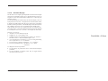
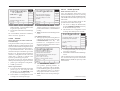
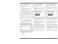
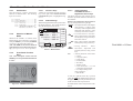
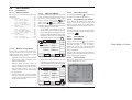
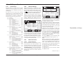
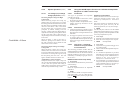
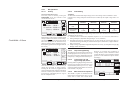
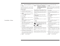
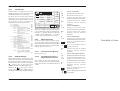
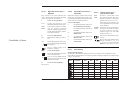
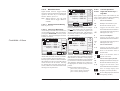
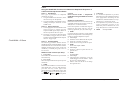
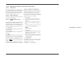
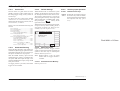
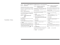
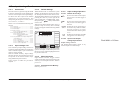
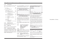
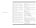
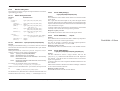
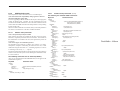
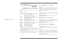
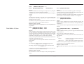
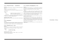
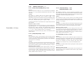
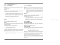
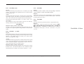
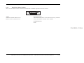
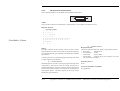
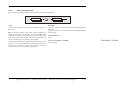
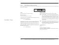
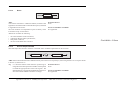
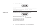
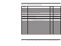
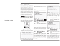
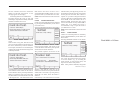
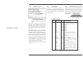
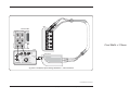
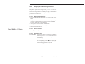
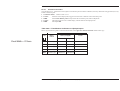
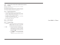
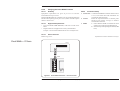
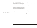
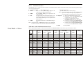
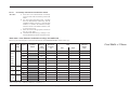
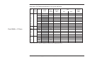
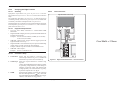
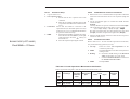
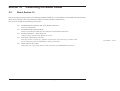
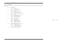
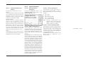
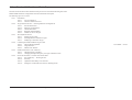
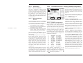
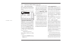
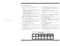
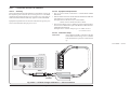
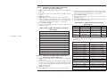
4.5.3.2
UUT Triggers
The trigger can be routed via any head (except
9550), but a standard SMA to BNC coaxial
cable can be used instead, to save the cost of an
extra head. The reason for establishing five
channels is to permit use of four signal heads to
carry a full range of signals, plus an extra
channel to accommodate the trigger input, if
necessary. When a cable is fitted instead of a
head, it cannot carry the full range of signals.
Pressing the 'TRIGGER CHANNEL' soft key
provides a screen which permits a user to
assign a channel to trigger outputs:
As the screen shows, as yet no channel has
OFF
CHANNEL
CHANNEL
CHANNEL
CHANNEL
CHANNEL
Final Width = 215mm
TRIGGER
CH 1
SIGNAL CH1 5ØΩ
TRIGGER NONE
>
>
>
>
>
1
2
3
4
5
9530 1.1Ghz 150ps
9530 1.1GHz 150ps
9510 1.1GHz 500ps
No Head
No Head
O/P Amplitude = 2Ø.ØØØ mVpk-pk
Frequency = 1.ØØØØ kHz
TODAY'S DATE
EXIT
TRIGGER
CH 3
TRIGGER
CH 4
TRIGGER
CH 5
TRIGGER
RATIO
CABLE
SELECT
been allocated to triggers. This is confirmed
by the legend in the top central box and the
right side screen keys.
On the screen, the 'TRIGGER CHANNEL' label
has changed to 'SIGNAL CHANNEL', and
pressing this will revert to the previous screen
of para 4.5.3.1. so this key toggles between
the signal and trigger selection screens.
Pressing the 'EXIT' key will revert back to the
standard DC/Square screen of para 4.5.2.
Note that in the bottom right corner of the
screen, the expected load selection label has
disappeared, because as yet no trigger channel
has been selected. The label will be reinstated
if an active head is chosen to carry the trigger,
but if a cable is used a trigger load of 50Ω will
always be expected.
4.5-2
OFF
TRIGGER
NONE
TIME
SIGNAL
CHANNEL
TRIGGER
CH 2
4.5.3.3
Trigger Channel Selection
Any of the channels can be selected for trigger,
so long as it is not already allocated as a signal
channel. In the screen of para 4.5.3.2, the top
central box shows Channel 1 as the signal
channel, and unavailable for trigger.
Attempting to use an occupied channel will
result in a 'bleep' and an error message.
If it is necessary to use an occupied channel for
triggers, its allocation as a signal channel must
be de-selected. Similarly, a channel already
occupied as a trigger channel cannot also be
used as a signal channel. The first use to be
allocated to a channel is dominant, and must be
first de-selected to change its use.
Pressing an unoccupied channel key will
highlight the key's label and change the legend
in the top central box. For instance, pressing
the 'TRIGGER CH 3' key has the following
effect:
SIGNAL
TRIGGER
CHANNEL
CHANNEL
CHANNEL
CHANNEL
CHANNEL
>
>
>
>
>
1
2
3
4
5
TRIGGER
CH 1
CH1 5ØΩ
CH3 5ØΩ
9530 1.1Ghz 150ps
9530 1.1GHz 150ps
9510 1.1GHz 500ps
No Head
No Head
O/P Amplitude = 2Ø.ØØØ mVpk-pk
Frequency = 1.ØØØØ kHz
TODAY'S DATE
EXIT
TIME
SIGNAL
CHANNEL
TRIGGER
RATIO
CABLE
SELECT
TRIGGER
CH 2
TRIGGER
CH 3
TRIGGER
CH 4
TRIGGER
CH 5
TRIGGER
NONE
LOAD
5ØΩ 1MΩ
The expected load value can be changed from
50Ω to 1MΩ using the bottom left corner
toggle key.
4.5.3.4
Cable Selection
If it is intended to use a cable instead of a full
head to convey the trigger, then a channel with
no head fitted must be selected. In this case, for
example, pressing the 'TRIGGER CH 5' key has
the following effect:
Section 4: Using the Model 9500B — DC/Square Function
OFF
SIGNAL
TRIGGER
CHANNEL
CHANNEL
CHANNEL
CHANNEL
CHANNEL
>
>
>
>
>
1
2
3
4
5
TRIGGER
CH 1
CH1 5ØΩ
CH5 5ØΩ
9530 1.1Ghz 150ps
9530 1.1GHz 150ps
9510 1.1GHz 500ps
No Head
No Head
O/P Amplitude = 2Ø.ØØØ mVpk-pk
Frequency = 1.ØØØØ kHz
TODAY'S DATE
EXIT
TRIGGER
CH 3
TRIGGER
CH 4
TRIGGER
CH 5
TRIGGER
NONE
TIME
SIGNAL
CHANNEL
TRIGGER
CH 2
TRIGGER
RATIO
CABLE
SELECT
LOAD
5ØΩ 1MΩ
This channel must be allocated as a 'cable'
channel; accessed by pressing the 'CABLE
SELECT' key. A new screen is presented:
OFF
SIGNAL
TRIGGER
CHANNEL
CHANNEL
CHANNEL
CHANNEL
CHANNEL
1
2
3
4
5
>
>
>
>
>
CH1 5ØΩ
CH5 5ØΩ
9530 1.1Ghz 150ps
9530 1.1GHz 150ps
9510 1.1GHz 500ps
No Head
No Head
O/P Amplitude = 2Ø.ØØØ mVpk-pk
Frequency = 1.ØØØØ kHz
TODAY'S DATE
CABLE
CH 1
CABLE
CH 2
CABLE
CH 3
CABLE
CH 4
CABLE
CH 5
TIME
EXIT
Pressing the 'CABLE CH 5 ' key has the
following effect:
OFF
SIGNAL
TRIGGER
CHANNEL
CHANNEL
CHANNEL
CHANNEL
CHANNEL
1
2
3
4
5
>
>
>
>
>
CH1 5ØΩ
CH5 5ØΩ
9530 1.1Ghz 150ps
9530 1.1GHz 150ps
9510 1.1GHz 500ps
No Head
Trigger Cable
O/P Amplitude = 2Ø.ØØØ mVpk-pk
Frequency = 1.ØØØØ kHz
TODAY'S DATE
CABLE
CH 1
CABLE
CH 2
CABLE
CH 3
CABLE
CH 4
CABLE
CH 5
TIME
EXIT
Having made the selection, pressing 'EXIT'
returns to the trigger selection screen:
Descriptions assume 9500B/1100