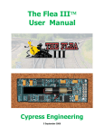
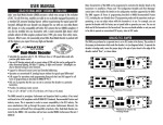
1
GAUGEMASTER
PRODIGY ADVANCE
--- WIRELESS --DCC03 USER MANUAL
Version 1.1 2009
What’s in the Box
Please check the contents are correct and free from damage, contact us
directly if you are in doubt
TABLEOFCONTENTS
1 Getting Started
Introduction
DCC Basic Background
Specifications and Features
System Menu Summary Chart
2 Operation
Quick Start
Connecting to Your Layout
Running a Loco
Controlling Accessory Functions
Recalling Locos
Saving Locos
Deleting Locos
Emergency Stopping
Speed Steps
Yard Mode On/Off
Fast Clock
Overload and Short Circuit
Cab Setup
Setting Cab Addresses
Setting the Total Number of Operational Cabs (Cab #1)
Adding More Than 3 Cabs
Setting Last Cab Allowed to Program Locos on the Main Track (Cab #1)
Setting Last Cab Allowed to Program on the Program Track (Cab #1)
Programming Decoders
Programming Loco on the Program Track
Programming Locos on the Main Track
Reading Loco’s Decoder Values on the Program Track
Configuration Variables – CVs
Most Commonly Used CVs
A Word About CV #29
Consisting
Advanced Consisting
Programming Advanced Consists
Running Advanced Consists
Clearing Advanced Consists
Universal (Old-Style) Consisting
Programming Universal (Old-Style) Consists
Running Universal (Old-Style) Consists
Clearing Universal (Old-Style) Consists
Fast Clock
Setting Fast Clock (Cab #1)
Setting Time (Cab #1)
Setting Time Rate (ratio) (Cab #1)
Setting AM/PM 24hr Time (Cab #1)
Accessory Decoders
Selecting Accessory Decoders
Accessory Routes
Setting Accessory Decoder Routes (Cab #1)
Running Accessory Routes
Clearing Accessory Routes
3 Trouble Shooting
General Trouble Shooting
Checklist for General Problems
Special Trouble Shooting
Contact Details
Getting Started
Introduction
Note Although there are Quick-start instructions on the back of the Cab/ Handheld, please read
these instructions thoroughly to better understand and enjoy your Prodigy Wireless DCC
system.
Your Prodigy Wireless system consists of a receiver base unit, a wireless handheld transmitter, fourrechargeable, 600mAh NiMH AAA batteries, and a short cord for recharging the wireless handheld.
For best operation, the receiver base unit should not be placed under the layout in a “tangle of wires” or
where scenery mesh screening may interfere with the radio transmissions.
The wireless handheld comes complete with on-board rechargeable batteries. The battery level should
be checked prior to using the handheld for the first time. Best operation is accomplished with fully
charged batteries. 5.5 volts is maximum voltage, and the handheld should be recharged anytime the
indicator reads 4 volts or below. There is a power switch on the right side of the handheld. The handheld
should be switched off when not in use to conserve battery life, and when recharging the on-board
batteries. You can use the handheld while recharging the batteries; however, this will increase the
charge time. The handheld has the same cable connection on the bottom as the tethered handhelds. To
recharge the batteries, simply plug the supplied short cable into the bottom of the handheld, and the
other end of the cable into the cab jack on your base unit. If you wish, you can substitute four AAA nonrechargeable alkaline batteries for use. Normal charge time with the handheld powered off will be
approx. 5 hours. If you change the supplied rechargeable batteries with rechargeable batteries with a
higher mAH rating, both the operating time and the charging time will increase.
Caution do not plug the handheld(s) into the base unit if you installed no rechargeable alkaline
batteries. Non-rechargeable alkaline batteries are throwaway and are not designed to be
recharged. Do not mix alkaline and rechargeable batteries together, and do not attempt to
recharge alkaline batteries inside the handheld.
You can do everything with this wireless handheld that you can do with its “wired” cousins: program on a
program track; or program on the main; acquire and run all locos; set up consists & routes; and access
accessory decoders. Button layout is similar to other MRC Prodigy handhelds, with the addition of three
new buttons:
PROG CV ON MAIN: This button lets you automatically go into CV programming of the locomotive you
are presently operating without having to press the program button, PROG, and ENTER numerous
times to reach this feature. You can enter this programming mode, change the decoder’s parameters,
and exit the program mode anytime you want and as many times as you want.
SAVE: This button is used to save the last five locos you were operating, or up to any five locos you
want to use in your next operating session.
Note Just turning off the wireless handheld power switch does not automatically save your
locomotives in the recall stack for your next operating session.
BAT VOLTAGE: This is your battery voltage indicator button. Just press it to monitor the voltage level
present in the on-board batteries; the display will show bV and the voltage level. 5.5 volts is maximum
voltage, and the handheld should be recharged anytime the indicator reads 4 volts or below.
Note The Prodigy Wireless does not support NON-decoder equipped or analog locos.
Specifications and Features
Input: 15-16 volts DC, 3.5 Amps. It comes with a universal switching power supply (good for USA and
Europe)
Output: DCC signal with 14.5 V amplitude, for HO and N scales
Maximum Current: 3.5 Amps
Note Although you can draw more than 3.5 amps for short periods of time, it is not recommended
Maximum number of Cabs: Use up to 32 Cabs
Address Capability: 2-digit (1-127) or 4-digit (1-9,999)
Speed Steps: 14/28/128
Accessory Functions: 29 (F0-F28)
Advanced and Universal Consisting
Program Loco on Program Track
Program Loco on Main Track
Read Loco on Program Track
Frequency: 433 MHz
FCC ID: BTQ170495
System Menu Summary Chart
Most functions are initiated by pressing their associated keys. However, there are ten functions initiated
by pressing the SYS key followed by a numeric key (0-9). The following table summarizes these ten
functions and the information about each function is found in the manual.
Keys Function
SYS + 0 Clear routes
SYS + 1 Set time
SYS + 2 Set time ratio
SYS + 3 Yard on/off
SYS + 4 Set time mode: AM/PM/military
SYS + 5 Set routes
SYS + 6 View your Cab address
SYS + 7 Set last Cab allowed to program locos on the Main Track
SYS + 8 Set last Cab allowed to program locos on the Program Track
SYS + 9 Set total number of operational Cabs
Quick Start
Connecting to Your Layout
Follow the diagram to connect the Command Station (base unit) to your layout.
1. Using a small flat-bladed screwdriver, attach two wires from the Main Track layout to the terminals
marked Main Track and two wires from the Program Track to the terminals marked Program Track.
2. Plug the power supply into the base unit.
3. Plug the AC line cord into a wall outlet.
4. Charge the batteries in the handheld, if needed.
5. Turn power switch on the handheld to the “On” position.
6. Double check all wiring, the power light should be on and you are ready to run your decoder
equipped locos.
Running a Loco
To run a loco, you have to first know its address. Most decoders you purchase have the factory default
address #3. Read your decoder and/or loco manual for your decoder address.
To select a loco, press the LOCO key. Using the numeric keypad (0 - 9), enter the loco address. Press
ENTER. You have just acquired the loco.
The Cab will automatically remember the loco address for later recall.
Use the DIRECTION key to set the loco’s direction. Turn the THROTTLE knob slowly to increase the
loco’s speed. The selected loco, or current loco, will begin moving. You can also tap the +1 or -1 to
adjust the loco’s speed. Do not hold the -1 key, since this is also the DEL key and will delete the loco.
To toggle the headlight (F0) on or off, press 0.
Note A blinking loco address indicates that another Cab is also controlling that loco. This is just a
reminder and does not affect your control of the loco. However, since two Cabs are trying to control the
same loco simultaneously, the loco may not act as you expect. One operator will have to relinquish
control of the loco by deleting the loco from his Cab for proper operation.
Controlling Accessory Functions
To control accessory functions F1 - F9, press 1 - 9. To control F10 - F28, press SHIFT, then input the
two digit function number. Only functions up to F12 will show in the display, F13 to F28 will be
activated but will not be displayed on the screen.
The left LCD display shows that the current loco is 3802 running in reverse at a speed of 102. Its
accessory functions F1 and F11 are on.
Recalling Locos
To call up previous locos stored in the memory, press RECALL. You can recall up to 25 locos.
Saving Locos
To save the last five locos in use for the next operating session, press SAVE before turning off the
handhelds power switch. Before switching off the power switch on the handheld, recall back to the five
locos you wish to use in your next session, making sure all functions are off and the throttle is set to
zero. After you have reset your five locos, press SAVE. Then turn off the power switch on the handheld
and then shut down the power to your DCC system and layout.
Tip Use the DELETE button to remove any unused locos from the stack before saving your favorite five.
Note Although the Cab can recall up to 25 locos for operation, if you “power off” the Cab from the base
unit, it will only retain the last five locos previously saved.
Make sure to press SAVE before powering off.
Deleting Locos
The Cab can store up to 25 locos. If you select a new loco when the Cab is full, the new loco will replace
the current loco. The current loco will be lost. To prevent this, we recommend you recall unused locos
and delete them by pressing and holding DEL for 2 seconds.
Emergency Stopping
For emergency stopping of the current loco, press STOP. Pressing and holding STOP for 2 seconds will
stop the Main Track output. The 2 lights on the base unit will blink. To restore the Main Track output,
press and hold STOP for 2 seconds again.
Speed Steps
Speed steps are incremental steps the loco takes to go from 0 to top speed. There is three speed steps:
14, 28 and 128. The higher the speed steps setting, the higher the number of different speeds on which
the loco can operate. When you enter a new loco address (an address that has not been stored in the
Cab’s memory), Prodigy Wireless will set 28 speed steps as the default setting for that address. In order
to operate your loco properly, you may need to change the speed steps setting to match the decoder’s
speed steps. To select other speed steps settings, press SPD STEP repeatedly until you see your
desired speed steps setting. Then press ENTER. The selected speed steps setting will apply only to that
address.
Note Use of the speed step button will not alter the speed step originally programmed into the decoder.
It only matches the throttle to the decoder.
Yard Mode On/Off
To toggle the Yard Mode feature on or off, press SYS and 3. In standard throttle mode, the throttle only
controls loco speed. When the Yard Mode feature is on (“Yard” displayed on LCD), the yard throttle will
control both the speed and direction of the loco. Let’s explain how to use the Yard throttle. When the
loco is traveling forward, turning the yard throttle clockwise will increase the loco’s speed. Turning
counterclockwise will decrease its speed until 0. Continuing turning counterclockwise will reverse the
loco’s direction. Continuing turning counterclockwise will increase the loco’s speed in the reverse.
Turning clockwise will decrease its speed in the reverse until 0. Continuing turning clockwise will reverse
the loco’s direction and set it forward.
Fast Clock
To view the fast clock, press TIME. The time will replace the address display on the LCD. You can still
run the current loco while the time is displayed. To return to the loco address display, press TIME again.
The time information is stored in the base unit and transmitted to the Cab. Each Cab displays the same
time. The left LCD display shows time of 8:02AM. The current loco is moving forward at a speed of 102.
Overload and Short Circuit
The base unit is rated at 3.5 amps. It is up to you to note how many locos and accessories can be run
on the layout at the same time without triggering the circuit protector. If there is an overload or short
circuit, the base unit will stop Main Track output for 2 seconds then resume. Please remove the overload
or short circuit for proper operation. When operating larger layouts with numerous locos and accessories
being operated at the same time you may need a DCC power booster.
Cab Setup
Setting Cab Addresses
You can use up to 32 Cabs with the Prodigy Wireless. Each Cab must have a unique address. Any Cab
you purchase has the factory default address #1. Cab #1 is the Master Cab that can perform all
functions. Any additionally purchased Cabs are also Master Cabs and must have their addresses
changed from #1 to unique addresses.
To view your Cab address, press SYS and 6. The current Cab address will momentarily display. If you
wish to change it, enter a new address (1-32) followed by ENTER. Otherwise, press ENTER to exit. Do
not duplicate Cab addresses.
Setting the Total Number of Operational Cabs (Master Cab Only)
The more Cabs in use at one time, the slower the system response is from Cab to loco because the
base unit can communicate with only one Cab at a time. Setting the total number of operational Cabs
will speed up your Cab’s response time.
1. Make sure your Cab is the Master Cab (Cab #1).
Only the Master Cab (Cab #1) can set the number of Cabs allowed to operate on the DCC layout.
2. Press SYS and 9.
3. Using 0 - 9, enter the address of the last operational Cab. Press ENTER.
Example If you use 10 Cabs and program the Cab addresses #1 - #10, pressing SYS, 9, 10, and
ENTER will set the last operational Cab number to 10. The base unit will not spend time trying to
communicate to Cabs #11 - #32.
If you use 3 Cabs and program the Cab addresses #1 - #3, pressing SYS, 9, 3, and ENTER will set the
last operational Cab number to 3. The base unit will only communicate to Cabs #1 - #3. You will have a
really fast response time.
Adding More Cabs
The base unit of your Prodigy Wireless system has one Cab Jack that is used for charging the batteries
in the handheld(s) or for connection of one tethered Cab. If you need to use more tethered Cabs or you
want to install the Cab Jacks around your layout, you will need an Extension Plate. The wireless base
unit is able to power six tethered Cabs. If more tethered Cabs are needed, for every five Cabs you need
a special extension plate with a built in power supply Please contact us for more information.
Note The extension plates are not needed if you only use wireless Cabs.
Setting Last Cab Allowed to Program Locos on the Main Track (Master Cab Only)
This feature prevents “novice” operators on your railroad from mistakenly reprogramming everything on
the layout.
1. Make sure your Cab is the Master Cab.
2. Press SYS and 7.
3. Using 0 - 9, enter the number of the last Cab allowed to program on the Main Track. Press ENTER.
Example If you press the SYS, 7, 3 and ENTER. Cab #4 and above cannot program on the Main Track.
Setting Last Cab Allowed to Program on the Program Track (Master Cab Only)
1. Make sure your Cab is the Master Cab.
2. Press SYS and 8.
3. Using 0 - 9, enter the number of the last Cab allowed to program on the Program Track. Press
ENTER.
Example If you press SYS, 8, 2, and ENTER, Cab #3 and above cannot program on the Program track.
Programming Decoders
The Prodigy Wireless allows you to easily program most NMRA compatible decoders. It guides you step
by step through the programming process. No hexadecimal numbers are needed, to program decoders
with this system. The Prodigy Wireless allows you to program decoders on a separate Program Track or
on the Main Track layout, all without affecting any other locos operating on the Main Track.
Decoder Terminology
Note Before you start programming, please familiarize yourself with the following terminology.
Loco Address: The address is the number assigned to a decoder to identify the decoder.
Start Voltage: This is the voltage required to start the loco’s motor and overcome its weight and friction
to make it begin to move. You can program your loco with a start voltage so that it will begin to move as
soon as the throttle is turned.
Top Voltage: The top voltage (top speed) is the voltage (speed) at full throttle.
Acceleration Rate: This rate simulates the drag of a heavy load as the loco speeds up so when you
increase the speed setting, the loco will gradually increase its speed.
Deceleration Rate: This rate simulates the drag of a heavy load as the loco slows down so when you
decrease the speed setting, the loco will gradually decrease its speed.
Programming Loco on the Program Track
1. Make sure your Cab is allowed to program on the Program Track.
2. Place the loco on the Program Track. Press PROG to select “Prog Prog Track”. Press ENTER.
3. First, “Adr” will flash, prompting you to program the loco address. Using 0 - 9, enter the loco address
followed by ENTER, or press ENTER to skip.
Note For the beginner or if you want to only program the loco address, you can stop right here.
Put the loco back on the Main Track. Select the loco by pressing LOCO then enter the loco address and
press ENTER. Now you can run the loco.
4. Next, “SV” will flash, prompting you to program the Start Voltage. Input data and then press ENTER.
5. Next, “Acc” will flash, prompting you to program the acceleration rate. Input data and then press
ENTER.
6. Next, “dEc” will flash, prompting you to program the deceleration rate. Input data and then press
ENTER.
7. Next, “TV” will flash, prompting you to program the Top Voltage. Input data then press ENTER.
8. Finally, “CV#” will flash, prompting you to program a CV (Configuration Variable).
At this point, you have already finished most of the decoder programming.
You can stop programming here by pressing ENTER.
9. If you want to program a CV, enter a CV number. Press ENTER. Then enter CV data. Press ENTER.
“CV#” will flash again, prompting you to program another CV. To skip, press ENTER.
Note Programming a CV with incorrect data can cause a decoder malfunction.
Read your decoder manual carefully before programming a CV
Programming Locos on the Main Track
Programming on the Main Track can save you the effort of moving a loco to the Program Track for
programming. However, you have to know the loco address in order to program on the Main Track.
Otherwise you have to program the loco on the Program Track. Not all decoders support the
Program on Main feature. Please read your decoder’s manual to check whether the decoder supports
this feature.
1. Make sure your Cab is allowed to program on the Main Track
2. To program on the Main Track, press PROG to select “Prog Main Track”.
Press ENTER. The current loco address will flash, prompting you to program the current loco.
3. To program the current loco, press ENTER; to program another loco, enter its address and press
ENTER.
4. The rest of the programming procedures are the same as the Programming on Program Track
procedures (see above). We recommend you bring the loco to a stop before programming because if
the moving loco has a bad pickup, it may fail to receive the program command, causing a malfunction.
Reading Loco’s Decoder Values on the Program Track
The Prodigy Wireless DCC system gives you the ability to read back CV values of a decoder equipped
loco on the Program Track. This feature is useful if you do not remember the decoder address or what
CV values your decoder has. Not all decoders support this feature. Please read your decoder’s manual
to check whether it supports this feature.
1. Place the loco on the Program Track.
2. Press PROG to select “rEAd Prog Track” then press ENTER.
3. First, “Adr” will flash, prompting you to read the loco address. Press ENTER to read or press SHIFT to
skip to the next item. It may take several seconds to retrieve the address. If the decoder does not
support read back feature, you will receive an “Err” (Error message).
4. Next, “SV” will flash, prompting you to read the Start Voltage. Press
ENTER to read or SHIFT to skip.
5. Next, “Acc” will flash, prompting you to read the acceleration rate. Press ENTER to read or SHIFT to
skip.
6. Next, “dEc” will flash, prompting you to read the deceleration rate. Press ENTER to read or SHIFT to
skip.
7. Next, “TV” will flash, prompting you to read the Top Voltage. Press ENTER to read or SHIFT to skip.
8. Finally, “CV#” will flash, prompting you to read a CV. To read a CV, enter a CV number and press
ENTER. After reading a CV, press ENTER. “CV#” will flash again, prompting you to read another CV. To
end the read process, press ENTER.
More about Decoder Read Back
Not all decoders support the read back feature. Although Prodigy Wireless has read back functions, it
may still fail to read back the decoders. This does not mean that your Prodigy Wireless is defective. No
DCC system in the world is able to read all decoders 100%. This will not affect the operation of the
decoder because you are always able to program your decoder.
Configuration Variables – CVs
Configuration Variables, also known as CVs, receive and hold entered data that allow the decoder to be
tailored to a specific loco or accessory. Some CVs are also called registers. The Prodigy Wireless DCC
system allows you to perform most basic programming without having to concern yourself with CVs or
registers. Of course, if you want to program CVs to custom tailor your decoders or select certain
functions, the Prodigy Wireless has this capability.
Most Commonly Used CVs
The CVs listed on the chart below are contained in almost all decoders, with additional CVs for extra
functions – sound or light – in more specialized decoders. See the decoder manufacturer’s instruction
manual for a list of CVs contained in that specific decoder and what values to enter for those CVs.
A Word About CV #29
CV29 is the most important CV of the decoder. Improperly programming the CV29 may cause decoder
malfunction. We do not recommend you program CV29 yourself because the unit will take care of it for
you in most cases. When you program your decoder’s address with Prodigy Wireless, it will
automatically program CV29. If you want to reverse the loco’s polarity or set 14 speed steps, you have
to reprogram CV29 after programming the loco’s address. Please use the following table to reprogram
CV29.
More About Programming Locomotive Address on the Program Track or Main Track
To program a locomotive address involves programming a series of CVs such as CV1, CV17, CV18,
CV19 and CV29. This can be somewhat complicated. For most decoders, Prodigy Wireless
automatically handles this for you when programming the loco address. However, it may fail to program
some old decoders and some new sound decoders made by QSI®. It does not mean that you cannot
program these decoders. It only means you cannot use the Prodigy Wireless’s easy address
programming feature. For QSI® decoders please refer to your decoder’s manual and use CV
programming to program the loco address.
Prodigy Wireless' default setting CV29 = 2 CV29 = 34
Change polarity only CV29 = 3 CV29 = 35
Change to 14 speed steps only CV29 = 0 CV29 = 32
Change polarity & 14 speed steps CV29 = 1 CV29 = 33
CV # Register # Function
1 1 Short address
2 2 Start voltage
3 3 Acceleration rate (momentum)
4 4 Deceleration rate (momentum)
5 --- Top voltage
6 --- Mid voltage
7 --- Manufacturer version #
8 --- Manufacturer ID #
17 --- Extended address - upper & lower bytes, 4 digit addresses
18 --- Extended address - upper & lower bytes, 4 digit addresses
19 --- Advance consist
29 5 Configuration data #1
Note If you want to program a CV or a group of CVs for the current locomotive you are running on the
Main Track, press CV and enter the CV number and the data value.
For some old decoders, you have to skip the Addr programming and use the CV program mode to
program CV29 with a value of 2 and CV1 with a short address (1-127). Detailed steps are as follows:
1. Press Prog to select Prog Prog Track
2. Press Enter six times until CV# displays on the screen
3. To select CV29, press 29 and Enter
4. CV data displays. Press 2 and Enter
5. CV# displays again. Select CV1 by pressing 1 then press Enter
6. CV data displays. Press the loco address (1-127) and then Enter
Consisting
Sometimes more than one loco is needed to haul heavy loads. These grouped locos are known as a
multiple unit or a consist. The Prodigy Wireless DCC system allows you to build consists quickly and
easily. There are two types of consisting methods, Advanced Consisting and Universal or Old Style
Consisting.
Advanced Consisting
You can only apply Advanced Consisting to a mobile decoder that has CV19 to support this feature.
When you program a loco into an Advanced Consist, you actually program the consist number into the
decoder’s CV19, which will override the decoder’s original address. Therefore, the loco will no longer
respond to commands addressed to its original address, but rather only to commands addressed to the
consist number. All decoders in the consist will receive the command addressed to the consist number
at the same time and act as one until you clear the consist. The base unit does not hold the consist
information. With Advanced Consists, always remember to clear the consist when you are finished or
the locos will still run as part of the consist next time you use them.
Programming Advanced Consists
1. Press CONSIST until “Cons SET” flashes in the LCD display. Then press ENTER.
2. “Cons #” will display, prompting you to enter a consist number. Enter a consist number (a short
address 1-127) followed by ENTER.
Note Write down the consist number. You will need it later to clear the Advanced Consist.
3. “Add Loco” will display, prompting you to add a loco into the consist group. Enter the address of a
loco you want to add. Press DIRECTION if you want the loco’s direction reversed (forward is the default
setting). Then press ENTER.
4. “Add Loco” will display again, prompting you to add another loco into the consist group. You can add
as many locos into the consist as you would like. To end programming, press ENTER.
Running Advanced Consists
Running Advanced Consist is just like running a single loco.
After setting up your consist group, use the consist number to run the consist.
1. Press the LOCO key. Make sure “Loco” appears on the LCD. If not, press the LOCO key again. Enter
the consist number and press ENTER.
2. Turn the throttle and all the locos in the consist will start moving together. To control an individual
loco’s accessory functions use either the consist number or the loco’s original address. Read your
decoder’s manual to find how to control the accessory functions.
Clearing Advanced Consists
1. Press CONSIST until “Cons cLr” flashes in the display. Then press ENTER.
2. “Cons#” will display, prompting you to input the consist number. Enter number of the consist you want
to clear and press ENTER.
Once you clear the consist, each loco will respond immediately to its original speed command.
Note If you forget the consist number, each loco’s address in the consist must be reprogrammed on the
Program Track, or program CV19 to zero, in each loco.
Universal (Old-Style) Consisting
This feature allows you to use older decoders that do not have CV19 to support Advanced Consisting. In
this type of consisting, the base unit stores all the information of the consisting locos and makes them
run as a single loco. When you adjust the speed of the lead loco, the base unit distributes the speed
setting to all the original loco addresses in the consist by sending the speed command to each individual
loco. Although the consist acts as one loco, there is a slight time lag between the locos you may not be
able to detect.
Locos consisted in this fashion will revert to their original addresses and direction settings when
removed from the layout. If they are removed from the layout and placed back onto the layout during the
same session, they will remain consisted. They will not be “consisted” if removed to another layout.
The Prodigy Wireless DCC system allows only ONE Universal Consist at a time regardless of how many
Cabs are in use. One Universal Consist per system, not per Cab. Once programmed, the base unit will
remember the consist group until you clear it. Turning off the base unit power will not clear it.
Programming Universal (Old-Style) Consists
1. Press CONSIST until “oLd SET” flashes in the display. Then press ENTER.
2. “LEAd Loc” will flash, prompting you to enter the address of the lead loco. Enter the lead loco’s
address. Press DIRECTION if you want the loco’s direction reversed (forward is default setting) and
press ENTER.
3. “Add Loco” will flash, prompting you to add another loco into the consist group. Enter a loco address.
Press DIRECTION if you want the loco’s direction reversed (forward is default setting) and press
ENTER.
4. “Add Loco” will flash again, prompting you to add another loco into the consist. You can control up to
4 locos total (including the lead loco) in a Universal Consist. To end programming, press ENTER.
Running Universal (Old-Style) Consists
Note Running a Universal Consist is different from running a single loco.
After setting up your consist group, use the lead loco’s address to run the consist.
1. Press CONSIST then LOCO. Make sure “Cons” appears on the LCD display.
2. Enter the address of the lead loco and press ENTER.
3. Turn the throttle and all the locos in the consist will start moving together.
4. To control accessory functions, use each loco’s original address.
Note When running a Universal Consist, LCD shows “Cons.” When running an Advance Consist, LCD
shows “Loco.”
Clearing Universal (Old-Style) Consists
To clear a consist, press CONSIST until “Cons oLd cLr” flashes in the display. Then press ENTER.
Turning off the power on the base unit will not clear the consist.
Once you clear the consist, each loco will immediately respond to its original speed command.
Note always clear a Universal (Old-Style) Consist when you are finished with it.
Fast Clock
Setting Fast Clock (Master Cab only)
Only the Master Cab (Cab #1) can program the time, time ratio, and AM/ PM or (24 hr) time. The time
settings entered by the Master Cab are stored in the Prodigy Wireless DCC system base unit memory.
The settings will remain unchanged until you reprogram them. The time is sent to all Cabs operating on
the layout so railroad schedules can be maintained.
Setting Time (Master Cab only):
1. Make sure your Cab is the Master Cab.
2. Press SYS and 1. The current time will be momentarily displayed.
3. Enter the new time. Press ENTER.
Setting Time Rate (ratio) (Master Cab only):
The time rate is how many real seconds are in one fast clock minute.
Example Rate 1 means that one real second equals one fast clock minute, or 60 times as fast as real
time. Rate 30 means 30 real seconds equal one fast clock minute, or twice as fast as real time. Rate 60
means 60 real seconds equal one fast clock minute, or real time.
1. Make sure your Cab is the Master Cab.
2. Press SYS and 2. The current rate will be displayed for a second.
3. Enter the new ratio. Press ENTER.
Setting AM/PM or 24hr Time (Master Cab only):
1. Make sure your Cab is the Master Cab.
2. Press SYS and 4. Either “AM”, “PM” or nothing (military) will display on the LCD.
3. Repeat step 2 above to select the desired setting.
Accessory Decoders
The Prodigy Wireless will operate most NMRA compatible accessory decoders.
Selecting Accessory Decoders
1. Press ACCY. Using 0 - 9, enter the accessory decoder address. Press ENTER.
2. “1or2” will display reminding you to press only 1 or 2 to control the accessory. Press 1 to turn the
accessory on and 2 to turn it off. You can keep pressing 1 or 2 until you are done with accessory.
3. Press ENTER to escape accessory operation.
Accessory Routes
Grouping of turnouts (or accessories) can be consisted to form a route.
The Prodigy Wireless DCC system allows up to 31 routes and up to 8 accessories in each route. Please
do not set a route number higher than 31, nor add more than 8 accessories into one route.
Setting Accessory Decoder Routes (Master Cab only)
1. Press SYS and 5.
2. “Route SET” appears in display. Press ENTER.
3. Enter route number (1 – 31). Press ENTER.
4. “Add Accy #” will display. Using 0 - 9, enter an accessory address (1 to 255).
If you want this accessory (turnout points) to move in a direction opposite its normally programmed
direction (reverse polarity), use DIRECTION to set its direction. Press ENTER.
5. “Add Accy #” will display again, prompting you to add another accessory into the route. Repeat above
steps to enter up to 8 accessories into one route.
6. When finished setting up your route, press ENTER.
Running Accessory Routes
1. Press ROUTE. Enter the Route number you wish to run. Press ENTER.
2. “1or2” will display reminding you to press only 1 or 2 to select the routes.
Clearing Accessory Routes (Master Cab only)
1. Press SYS and 0. Then press ENTER.
2. Enter the route number. Then press ENTER.
General Trouble Shooting
It takes the Command Station, the decoders and your layout to make the DCC system work. This
Trouble Shooting Section has been arranged in a manner easiest for you to find the cause of your
problem. Please go through this section in the exact order it appears because each following set of
instructions assumes that the preceding set has been tested and that component of the DCC system
found not defective.
1. Plug in the power supply of the base unit. The pilot light should turn on.
If not, make sure the power supply is securely plugged into the base unit and into a working AC wall
outlet. Then unplug the power, wait 3 seconds and plug back in. If power light still does not turn on, send
the unit in for repair.
2. Check the Main Track output.
Place an analog loco or test light on the Main Track. The loco should buzz or the test light should light. If
not, check all connections and make sure the rear green plug is securely plugged in. Make sure the
screws on the green plug are tightened on the wire and not on the wire cover (insulator). If the analog
loco still does not buzz or the test light does not light, send the unit in for repair. It is better to use a
V.O.M (multi-meter) on the A.C. scale to check for track power, as DCC track power is A.C., not D.C.
3. LCD does not display anything.
The Cab LCD should display the current loco when the power is on. If not, check the battery voltage
level. If recharging the batteries does not help, send unit in for repair.
4. Check the communication between the base unit and the Cab.
Press 2. F2 should momentarily display on the LCD and the Link light should blink. If not, set the Cab to
be the Master Cab (Cab #1) by pressing SYS, 6, 1, and ENTER. Make sure there is no other Master
Cab in the system and try again. If there is still no communication, send the unit in for repair. If there is
communication, you may have the wrong Cab setup. Read the Cab Setup section.
5. Your loco may have a pickup problem.
You should periodically clean your track and your loco’s wheels. Oxide coating or dirt on either the track
or loco’s wheels often causes intermittent and jerky operation.
If you pass the above steps, your Command Station and Cabs are fine. The problem may lie in
the decoder.
6. Your decoder may have lost its memory or is in Advanced Consist mode (CV19 is not 0).
Reprogram the loco address and try again.
7. Your decoder may have too much momentum. Program the loco with zero acceleration and
deceleration rates.
8. The base unit may have a Universal Consist controlling your decoder.
Clear the old consist by pressing CONSIST until “Cons oLd cLr” flashes in the display. Then press
ENTER.
9. The current loco speed command may not match the decoder’s speed steps.
Reprogram your decoder’s address. When you program the decoder with Prodigy Wireless it will
automatically set the decoder’s speed steps to 28/128. Select 28 or 128 speed steps on the base unit
and then try to run the loco.
10. Check the decoder wiring and make sure everything is correctly installed.
11. Remove the decoder and test it on a decoder tester to make sure the decoder is fine.
12. If the decoder is fine, check the loco to make sure the loco is fine before installing the
decoder.
Checklist for General Problems
1. Clean your layout and the loco’s wheels.
2. Check the layout’s wiring.
3. Reprogram loco address and other data.
4. Check battery voltage level.
5. Reset the base unit by unplugging power supply.
6. Check loco for proper decoder installation.
7. Check wiring from the base unit to your layout.
8. Check for short circuits and/or stray objects lying across track rails.
9. Make sure the Link light flashes when you press F2.
Special Trouble Shooting
Base unit power light is on but Cab does not display anything on the LCD display
1. Check the Cab battery voltage level.
2. Replace the batteries, if needed.
3. Try another Cab.
The loco’s headlight turns itself off
When you press 0 to turn on the loco’s headlight, the base unit will send the command to the decoder to
turn on the loco’s headlight. The base unit will not continuously send the accessory command to the
decoder like the speed command. When the loco hits a dirty track and loses its power, it will reset and
lose the accessory command. You should clean the track and the loco’s wheel to improve the loco’s
pickup.
During operation all locos stop responding
Unplug the power supply, wait 3 seconds and turn the power back on. If all the locos start to run and the
system shuts down again, you may have too many locos and accessories connected to track power.
Remove some locos and try again.
Your loco doesn’t work while other locos work
The decoder may have lost its memory. Reprogram loco address.
Your Cab doesn’t work while other Cabs work
Make sure each Cab address is unique. Make sure your Cab address is an operational address. Check
battery voltage. If the Cab still does not work, it may be a defective Cab.
Your Cab operates locos but cannot program on the Program Track
1. If the Link light does not flash when you enter a data and press ENTER, it may have been limited by
the Master Cab and is not allowed to program on the Program Track.
2. If the Link light flashes when you enter a data and press ENTER, then test the Program Track output.
To test, place an analog loco on the Program Track. During the programming process, the Link light
should be on and the analog loco should buzz. If the Link light is on and the analog loco does not buzz,
it is a defective Program Track output.
Your Cab operates locos but cannot program on the Main Track
The Master Cab may have limited it.
Your Cab operates locos but cannot program an Advanced Consist
The Master Cab may have limited it. Your Cab must be able to program on the Main Track to set an
Advanced Consist.
Our Prodigy Advance products carry a 1 YEAR GUARANTEE subject to the usual conditions
Your statutory rights are not affected
If you believe your unit is faulty, please telephone us in the first instance. We will
advise you of your best course of action. If it involves sending anything back, please
send it to the address below via insured post and packed securely.
Gaugemaster Controls Ltd, Gaugemaster House, Ford Road, Arundel, West Sussex BN18 OBN
Tel. No: 01903 884321 Fax. No: 01903 884377 Email: [email protected]
Web: www.gaugemaster.com
Registered in England. Reg. No: 2714470
The LCD main display icons are used in all operation to display both numbers
and symbols
Function icons are displayed when operating loco functions
FWD / REV and SPEED icons display the loco speed and direction of travel
The LAMP icon (F0) illuminates when the loco lights are activated
The LAST CAB icon is used in the system setting and the TIME RATE icon is
displayed when operating the (fast clock) time mode
The LOCO and CONS icons are displayed when operating and programming
locomotives and consists (DBL HEAD)
The MAIN / PROG / TRACK and DATA icons are displayed in programming
and (READ) modes, the SFT (shift) icon is used in function selection and
when selecting in READ mode
The table below can be used to list loco address and special