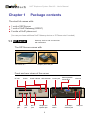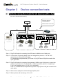
1
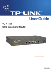
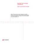
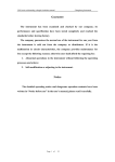
VoIP
Easy-to-use VoIP telephone
OnSIP VoIP Start Kit
User’s manual
Allwin Tech.Co.,LTD 2007 All rights reserved.
Quick guide to the manual
Thank you for purchasing AllWin Tech’s VoIP Telephone Start Kit.
The start kit is designed to provide you with the basic VoIP equipment
required to set up your own network telecommunication environment
within the shortest possible time.
After you have unpacked the package, please refer to the list of items
included in the package to make sure that no parts/accessories are
missing. Follow the instructions provided in the quick start guide and
connect all devices to the hub accordingly. All devices come ready
with virtual IP addresses preconfigured in factory settings, and simply
connect all adapters to a power socket, then start dialing and perform
system tests.
After the system tests have been completed, you can set up the devices
in different cities or countries depending on your needs. First, please
refer to Chapter 3 on configuring the IP address of the SIP Server, then
refer to Chapters 4 and 5 to configure the VoIP Gateway and IP Phone
sets according to different connected types, then register with the SIP
Server.
When you have completed the installation and configuration, you can
start using the starter kit to take advantage of free on-net calling or
international calls/calls to mobile phones with your ITSP account.
You can also configure the system with accounts at different
ITSP; please check with your ITSP for the relevant settings and
configurations.
Note: You may purchase additional IP Phone sets and VoIP Gateways
from AllWin Tech depending on your needs. Be sure to use optional
hardware of All Tech with the start kit to ensure the system’s normal
operation.For topics regarding VoIP Phone software, please refer to
Chapter 7 of the manual on registering free VoIP Pone software to your
own VoIP network.
Since we are unable to confirm if the specifications of software/
hardware produced by other VoIP product manufacturer conform to the
standard communication protocols, AllWin Tech does not guarantee
that any third party hardware will work normally with the start kit.
1.1 SIP Server and accessories with instructions
1.2 VoIP Gateway device and accessories with instructions
1.3 IP Phone sets and accessories with instructions
Chapter 2 Device connection tests
2.1 Connecting each device to the hub
2.2 Dialing test
Chapter 3 SIP Server configuration
3.1 IP configurations
3.2 Changing administrator’s account name and password
3.3 Basic function configurations
3.3.1 Account management
3.3.2 Overview of accounts online
3.3.3 Access call log
3.3.4 Monitoring On call status
3.3.5 Authorization rules
3.3.6 Group routing configurations
3.3.7 Backup/Restore to default settings
Chapter 4 VoIP Gateway configuration
4.1 Configuring network connected type
4.1.1 Connected with static IP
4.1.2 Connected with DHCP
4.1.3 Connected with PPPoE
4.2 Register to SIP Server
4.3 Regarding dial routing
4.4 Configuring basic functions
4.4.1 Automatic forwarding for incoming calls
4.4.2 Forwarding when the line is busy
4.4.3 Forwarding when incoming calls are left unanswered
4.4.4 Modifying configuration for your number
4.4.5 Using the VoIP Gateway for dialing to the local public telecommunication system
4.4.6 Backup/Restore to default settings
4.5 Backup/Restore to default settings
Chapter 5 Configuring IP Phone Handset
5.1 Configuring network connection
5.1.1 Connected with static IP
Table of Contents
Chapter 1 Package contents
Table of Contents
5.1.2 Connected with DHCP
5.1.3 Connected with PPPoE
5.2 Register to SIP Server
5.3 Regarding dial routing
5.4 Configuring basic functions
5.4.1 Automatic forwarding for incoming calls
5.4.2 Forwarding when the line is busy
5.4.3 Forwarding when incoming calls are left unanswered
5.4.4 Modifying configuration for your number
5.5 Backup/Restore to default settings
5.6 Modifying configurations for the phone set LCD panel
5.6.1 Check IP address
5.6.2 Modify IP address
5.6.3 Change ring tone for incoming call
Chapter 6 Using free VoIP software on the system
6.1 Configuring X-Lite
6.2 Configuring SJ Phone
Chapter 7 Instructions on using the system
7.1 Making VoIP calls
7.2 Configuring your ITSP account
7.3 Dialing directions
VoIP Telephone System Start Kit - User's Manual
Chapter 1
Package contents
The start kit comes with:
1 unit of SIP Server
1 unit of VoIP Gateway (G322C)
2 units of VoIP phone set
(You can purchase additional VoIP Gateway device or IP Phone sets if needed)
1.1 SIP Server
Gateway device and accessories
with instructions
The SIP Server comes with
SIP Server X 1
Adapter (12V/1.6A) X 1
Front and rear views of the server
CF slot
USB
port
Power
USB
port
Power indicator HDD indicator
Mic-in
jack
Headphone/
speaker jack
Power jack
Power
switch
PS/2 keyboard/
mouse jack
10/100Mps
network jack
VGA out
USB port
VoIP Telephone System Start Kit - User's Manual
1.2 VoIP Gateway device (2FXS+2FXO)
Gateway device and
accessories with instructions
The G322C Gateway device comes with
G300C Gateway device X 1
Adapter (12V/1.6A) X 1
RJ-45 100CM network cable X 1
RJ-11 1-1 telephone cables X 4
Front and rear views of the gateway device
LAN
WAN
FXS
FXO
Power jack
FXS: c onnects to a normal phone or
PBX central office line.
FXO: c onnects to a PSTN line or
PBX extension line.
OneInGate G322C product specifications
1. S upport up to a maximum of 4 ports of VoIP calls
simultaneously.
2. Support both H.323 and SIP protocols simultaneously.
3. S u p p o r t u p t o a m a x i m u m o f 4 G K / S I P S e r v e r
simultaneously.
4. Support both point-to-point and GK/Proxy Server platform
routing communications.
5. Built-in DHCP Server functionalities.
6. Support Static and dynamic IP from DHCP and PPPoE.
7. Support Multiple dialing plan/ Call hunting group.
8. Come with three 10/100 Mbps RJ-45 (UTP) LAN ports
(automatic detection)
9. Come with one 10/100 Mbps RJ-45 (UTP) WAN port (automatic
detection)
10.LED indicator to display various status such as PHONE, LINE,
POWER, STATUS, READY, WAN and LAN.
11.Support APS (Auto Provision Server)
12.Support various audio compression formats including G.723.1,
G.829A, G.711 and so forth.
13.Web configuration interface available.
14.WAN IP configure can be programmed by IVR via phone sets.
15.Support QoS and G.168 echo canceller.
VoIP Telephone System Start Kit - User's Manual
1.3 IP202 VoIP handset
Phone set and accessories with
instructions
The IP202 VoIP phone set comes with
IP Phone X 1
(with 1 PSTN port)
Coil cord for the
receiver X 1
RJ-45 100CM
network cable X 1
Adapter (9V/1.3A) X 1
Description of function buttons on the phone set panel
Access
Phone Book
Confirm/
Cancel
Scroll up/down
Check instant
messages
Redial
MESSAGE
Forwarding
settings
CONF
CALLS
Hold
MENU
Call log
Transfer
Main menu
selections
Volume
adjustment
Speaker
phone
Speed dial
buttons
Connection ports/jacks
Power jack
WAN
LAN
PSTN jack
VoIP Telephone System Start Kit - User's Manual
Description of various functions on the phone set panel
Item
Name
Description
1
CALLS
Shows unanswered calls, calls made, calls answered,
forwarded calls along with option to delete the call log.
2
FORWARD
Configures the phone set’s forwarding functions, including
forwarding, forwarding when the line is busy, forwarding when
unanswered, etc.
3
MENU
4
MESSAGE
Shows information such as instant messages or the number of
unanswered calls
5
M1~M6
Speed dial buttons; a total of six numbers can be assigned to
these buttons
6
PHONE BOOK
Accesses Phone Book
7
V
Confirm selection
8
X
Delete or cancel
9
▲
Page up
10
▼
Page down
11
+
Increase volume
12
–
Decrease volume
13
REDIAL
Redial last number called
14
HOLD
Puts a call on hold
15
TRANSFER
Transfer a call
READY (LED)
Stays on when registration of a server is successful; flashes
when registration is unsuccessful.
CALL
FORWARD(LED)
Stays on when any forwarding function is configured
successfully; stays off otherwise.
MSG(LED)
Flashes when you have an incoming message or unanswered
call; stays off otherwise.
INUSE(LED)
Stays on when a user is on the line; stays off otherwise.
Accesses the main function menu for the VoIP phone set,
including:
1. View:
1 Network Link
2 Ping Test
3 Device Status
4 Call by URL
2. Configure
1 Network
2 Time zone
3 Provision
4 Set SIP
5 Modify Password
3. General Setting
1 VoIP Ring Melody
2 Line Ring Melody
Ring Volume
VoIP Telephone System Start Kit - User's Manual
Chapter 2
Device connection tests
OnSIP VoIP Start Kit Quick Installation
2.1 Perform connection tests for all devices with a hub
Test all devices with a HUB
(Hub is not included in this start kit)
(HUB optional)
Follow this diagram to
Internet
connect all devices.
Default numbers are 101~104
HUB
RJ-45
RJ-45
Gateway
172.16.70.103
2FXS
LAN
WAN
DC9V
DC9V
WAN
SIP Server
WAN
LAN
Power
LINE
WAN
L4
2FXO
L3
L2
L1
DC12V
LINE
LAN
Power
RJ-11 cable
172.16.70.100
Power
IP Phone
IP Phone
101
102
Phone
Phone
172.16.70.101
172.16.70.102
104
103
PSTN Line
Step 1:Plug RJ-45 cable for connecting from SIP server's WAN to one of Hub ports.
Step 2:Connect both IP phone's WANs, which are assigned as phone no. "101" & "102",
respectively, to Hub with RJ-45 cables.
For abbreviation/comprehension, [IP-Phone-101] & [IP-Phone-102] will be used in this
quick guide later.
Step 3:Plug RJ-45 cable for connecting from gateway's WAN to one of Hub ports; connect two
phones to gateway's Line 3 & 4 with RJ-11 cables; by default, phone no. of gateway's
L3 & L4 are assigned to be "103" & "104", individually.
Later on, for abbreviation/comprehension,[Phone-103] & [Phone-104] will be used in this
quick guide.
Step 4:Make sure all equipment are fed with appropriate power.
Step 5:Make a phone call test among 101 to 104.
For more detailed information, please refer to OnSIP VoIP Start Kit User Manual.
VoIP Telephone System Start Kit - User's Manual
2.2 VoIP call testing
212
213
After you have set up your
VoIP network as shown in the
previous section, you will be
able to make VoIP calls between
phone sets with the 101~104
prefixes. If the cables have been
connected properly, you should
be able to make VoIP calls with
the phone sets.
Use any phone set
and call other number
inside on this network.
The 103 and 104 phone
sets are connected to
the Gateway;Normal
phone sets are not
included in the start kit
215
214
1. When connections between devices are normal, the displays on 101 and 102
phone sets should show SIP:101 and SIP:102 respectively. This means both
phone sets are registered on the SIP Server and ready to make and receive
calls.
2. Please pick up the receiver of any phone set (101~104) and call another number
in the same network (101~104) to see if the connection gets through.
3. Testing forwarding functions and 3-way conference calls:
When you have connected 101 to 102 in an on-net call, pressing the “Transfer”
button or the “CONF” button will put 102 on hold. User on 102 will hear the onhold music playing on the receiver.To forward the call to 103, the user on 101
will press 103 while the call is still on hold. Once the call is forwarded to 103, the
user on 103 will be connected to 101 first. When the user on 101 hangs up the
phone, user on 102 (which was put on hold) will be connected to user on 103.
This is how you would forward a call during an on-going connection.
Similar to the previous example, pressing the “Transfer” button (or the “CONF”
button) will connect 101 to 103 while putting 102 on hold. By pressing the CONF
button on 101, you can start a three-way conference among 101, 102 and 103.
4. If you encounter no problems while performing these tests, this means you can
now setup the devices for specific territories or countries and configure them by
referring to the directions provided in this manual.
VoIP Telephone System Start Kit - User's Manual
Chapter 3
SIP Server configuration
3.1 Configuring IP address
Connect your SIP Server appliance and
your PC to the hub with network cables.
HUB
First, modify your PC’s IP address so that
it is within the same domain as your SIP
Server’s default IP address.
Proceed through the following path to
configure your PC’s TCP:IP: (using
Windows XP as an example)
Start → Control Panel → Network and
Dial-up Connection → LAN Connection
Property → TCP/IP Property → Select
Obtain IP Address Automatically →
Confirm”.
Please input configurations as shown in
the image on the left:
IP address: 172.16.70.200
Subnet mask: 255.255.0.0
Press OK when you are done.
When you have finished the configuration, go to your IE browser and enter the SIP
Server’s default IP address of 172.16.70.100. You will be taken to a log in page similar
to the one shown in the image.
Enter the default user
name and password
User name:admin
Password:password
VoIP Telephone System Start Kit - User's Manual
Click on Open All to display all
control lists
Click on Network to access
the options as shown in the
following image
Enter information such as your static IP address and press “Confirm to edit”
when you have finished. The system will change its IP address and the screen
may not respond for roughly 10 seconds. Close the browser when an error
page is shown on your screen.
Since configurations such as IP address have been changed, you would have
to modify your PC’s TCP/IP settings to make sure it is consistent with the IP
address you have configured on your SIP Server.
Open a new IE browser and enter the new IP address you have modified in the
URL bar.
If you are uncertain about information such as your static IP address, please
contact your ISP provider.
VoIP Telephone System Start Kit - User's Manual
3.2 Changing administrator’s account name and password
Please change your administrator account name and password immediately
after you have setup your system to prevent your appliance from being
hacked into which may result in data damages.Here’s how to change your
administrator account name and password:
First, log in with the default account name (admin) and
password (password)
Click here
When you are taken to this page, click on Edit
You will now be in the profile modification page; enter your new account
name and password.
Fill in your new login name
Fill in your new password
Confirm your new password
Be sure to fill out the field for E-mail
After making the relevant changes, press Confirm to Submit for the changes to take effect. You will then
be taken to the login prompt; log in with your new account name and password, click on Reload at the
bottom left hand corner of the page to complete the process.
Please be sure to memorize or write down your new administrator account name and password.Should
you forget your account name or password, you will have to send the appliance back to AllWin Tech to
restore it to the default configuration and you will be subject to service charges.
VoIP Telephone System Start Kit - User's Manual
3.3 Basic function configurations
3.3.1 Account management
(1) Adding new Clients ID
Click on Client under Administrators
Click on <<Add>> on the upper right hand corner of the screen to enter the Add
Client screen as shown below.
Be sure to fill out the field for E-mail
ID: The VoIP prefix for the system is between 101~104; please fill in any other number
beginning with 1.
Name: The name entered here will be shown in Status – Client for easy identification of users.
Password: Enter password for your VoIP Gateway or IP Phone sets you have registered on the
SIP Server.
Confirm Password: enter the password you have just entered once more.
After all the relevant fields have been filled,
press Confirm to submit.
After you have added all the new
accounts, be sure to press the “Reload”
button at the bottom left hand corner of
the screen for the newly added Client
IDs to take effect.
10
VoIP Telephone System Start Kit - User's Manual
(2) Editing and deleting Clients ID
Click here to access the delete client page.
Check the boxes for
clients you wish to delete
Click on Edit to access the edit client page
Enter the updated
client information on
the corresponding
fields
To delete Client accounts, check the delete boxes for client
accounts you wish to delete or update the device before pressing
Confirm to Submit. After you have finished editing or deleting
client IDs, be sure to press the Reload button for your actions to
take effect.
11
VoIP Telephone System Start Kit - User's Manual
3.3.2 Overview of accounts online
Click on “Client” under Status to see all the registered users that are currently online.
When you have too many clients registered, you can use this
function to search for individual clients directly.
• Last Refresh: the time when the last refresh was performed
• ID: client accounts registered on the SIP Server; account names preceded
• Name: the name of clients registered on the SIP Server; allows easy identification.
• IP: shows clients’ IP addresses
The IP address shown on the top row represents clients’ real external IP
T
he IP address shown on the bottom row represents clients’ internal IP
(VIRTUAL IP).
• First time: indicates the time when clients first registered in the Server
• Last time: indicates the time when clients last registered in the Server
• Unregister: disconnects the client that have been logged into the server; simply check
the Unregister boxes for entrying in the Registry ID to unregister them and
press “Confirm to Unregister”.
• Refresh: refreshes the page.
• Unregister All: d
isconnects all clients who are logged into the server; simply click
on the “Unregister All” button.
12
VoIP Telephone System Start Kit - User's Manual
3.3.3 Access call log
Click on "CDR" under "Log" will allow you to see the call log; you can see all
records of call sessions made by any user within a particular time frame.
Caller ID: allows you to search for a particular caller ID by specifying the dates
and pressing Search. The system will show records that meet the criteria you have
provided.
• Caller: caller’s number and IP address.
• Answer: time when a call begins.
• Release: time when a call has been terminated.
• Called: recipients’ number and IP address.
•D
uration: if it shows “0”, this means that the connection for the call has not been
established successfully. Possible reasons include, the other end of the line is
busy or no one was available to answer the call. Refer to the reason provided
under “Reason” to determine the cause.
• Reason: why a call has been interrupted.
13
VoIP Telephone System Start Kit - User's Manual
3.3.4 Monitoring On call status
You can see how many users are currently making
VoIP calls through the server by clicking on “on Call”
under Status.
Access the following page to see:
・Caller: caller’s ID name and IP address.
・Called: number dialed and corresponding IP address.
・Answer: call out time.
・Duration(s): duration of a call (in seconds); if –1 is shown, this means the call did
not go through.
・Disconnect: disconnects clients that are in the middle of their connections; select
the callers to be disconnected by checking the boxes and press “Confirm to edit”.
・Disconnect All: disconnects all clients; simply click on “Disconnect All ”.
・Refresh: refreshes the page.
14
VoIP Telephone System Start Kit - User's Manual
3.3.5 Authorization rules
Click on Rules under System to configure the
authorization method for users login the SIP Server.
Access the following page to see:
・Mode:
1. Non: no authorization required; all client accounts can login.
2. ID: examines only client ID.
3. ID and password: clients may only login by entering the correct ID and Password
・Black Lists:
1. P
ress <<Edit>> to add or edit IPs in the black lists; press “Confirm to submit”
when you have completed the changes.
Activation of client ID and Password can be done by clicking
on Clients under Administrators; click on Edit to make
modifications.
When you make any changes, the “Remember to Reload”
reminder will appear. Be sure to press “Reload” for the
changes to take effect.
15
VoIP Telephone System Start Kit - User's Manual
3.3.6 Group routing configurations
With the system’s default configuration, you can dial 9 on your IP Phone set to
connect to a PSTN line through the VoIP Gateway’s first FXO port. Your call will be
made from the Gateway device to the local PSTN line to save international calling
charges. Relevant configurations on your SIP Server:
1. Click on Rules under System to access the rule configuration page.
2. Click on Group Route at the top to configure group routing
3. The default setting for the SIP Server in the start kit will take any calls made
beginning with 9 from a VoIP device (Gateway or IP Phone) that has been
registered on the SIP Server and forward it to the device registered at the VoIP
Gateway with the 103 ID.
2.
1.
3.
In addition, the VoIP Gateway will forward all calls made beginning with 9 to the
PSTN line connected to it’s first FXO port for call-in routing by default (refer to the
first point made in Chapter 4.3.1 on call-in routing).
Please avoid making changes to these default settings unless you are very familiar
with configuring the system for other needs, as this may cause the system to
malfunction.
16
VoIP Telephone System Start Kit - User's Manual
3.3.7 Backup/Restore to default settings
You can backup or restore Server related
configurations by using System Backup/Restore.
The files backed up with this function are only
limited to DataBase files; programs and CDR
reports will not be backed up this way.
(1) Backup
Select the data you wish to back up and press the “Backup” button. Files backed up will
appear in the “Backup Log” above. The backed up files are stored on the Server end.
You can choose from three options in the “Backup Add” field:
1. All: backs up all system data excluding CDR reports.
2. OnSIP : all data under “Basic” and “Rules”.
3. OnSIP User&Level&Clients: all data under “User”, “Level” and “Clients”.
If you wish to save the backed up files to another location, please click on “Download”
under “Backup Log”.
Another way to backup your files is by storing the files on a USB storage device.
If the device is connected to a USB storage device, simply press “USB Backup” to
perform backup.
17
VoIP Telephone System Start Kit - User's Manual
(2) Restore
There are two ways to restore files. The first is to click on Restore under
“Backup Log” if your files are stored on the Server end.
If your files are stored on the local end, please go to “Restore” and specify
where the files are being stored before pressing the “Restore” button.
Reminder: We strongly recommend that you back up your configuration files regularly.
AllWin Tech will not be held responsible for any damage caused by data loss/damages
in the course of the server’s operation.
18
VoIP Telephone System Start Kit - User's Manual
Chapter 4
VoIP GATEWAY configurations
4.1 Configuring network connection
You can use Windows’ built-in Web management interface to manage your VoIP
Gateway. To do so, connect a PC to the VoIP Gateway through its LAN port.
Since the VoIP Gateway is preset to activate DHCP server, please configure your
PC’s TCP/IP settings to “Obtain IP address automatically” in order for the VoIP
Gateway to obtain the right IP address. The VoIP Gateway’s default IP address
is 192.168.22.1; it will also assign a 192.168.22.x IP address to the PC that is
connected to its LAN port.
To configure your PC’s TCP/IP settings, go through the following paths (with Windows
XP as an example):
Start → Control Panel → Network and Dial-up Connection → LAN Connection Property
→ TCP/IP Property → elect Obtain IP Address Automatically → Confirm”.
To access the interface, start the IE browser on
your PC and enter http://192.168.22.1 in the
URL bar, as shown in the image on the left:
You will then be prompted to enter a user name
and password.
The default user name is “voip” and the
password is “1234”.
You must enter the correct user name and
password to access the interface.
You will be taken
to this Gateway
management interface
when you have
successfully logged in
as the administrator.
If you are not used
to using the English
interface, you can
change the interface to
Chinese.
19
VoIP Telephone System Start Kit - User's Manual
First, go to System setup and
choose WAN.
Then click on “Connected type”.
You will then be taken to the following screen. Please choose settings according to your
network environment.
The following section will cover brief descriptions for the three most commonly used
network connection types: Dynamic IP address / Static IP address / PPPoE.
4.1.1 Connected with dynamic IP
Choose this connection type if
you are using a DHCP server
or an IP sharer in your network
environment. There’s no need
to configure anything; simply
press OK.
Unless you are required to
make changes to the settings
due to specific needs, do not
modify any other settings here
to prevent the device from
malfunctioning.
20
VoIP Telephone System Start Kit - User's Manual
4.1.2 Connected with static IP
Choose this connection type if
your ISP provides you with a
static IP address for network
connection.
Please enter the required
information provided by your
ISP and press OK.
IP address assigned by your ISP:
enter the IP address provided by your ISP.
Unless you are required to
make changes to the settings
due to specific needs, do not
modify any other settings here
to prevent the device from
malfunctioning.
Subnet Mask:
enter the Subnet Mask provided by your ISP.
ISP Gateway Address:
enter the ISP Gateway address provided by your ISP.
4.1.3 Connected with PPPoE
Choose this connection type if
you have subscribed to typical
ADSL broadband services.
User Name
Enter your user name provided
by your ISP
Password
Enter your password provided
by your ISP
Please retype your password
Re-enter your password
Press OK when you are done
21
VoIP Telephone System Start Kit - User's Manual
4.2 Register to SIP Server
The VoIP Gateway’s two FXS ports are assigned to 103 & 104 by default. After you
have finished configuring your VoIP gateway connections, the next step is to modify
the VoIP gateway’s SIP Proxy URL. Here’s how to do it:
First, go to VoIP Setup and choose
Register Server.
Click on Server #1.
172.16.70.100 is SIP Server’s factory default virtual IP address. It is set up for you to
test your devices in a hub environment. When you want to setup the VoIP Gateway for a
different network environment, you need to configure the connection type (as covered in
the previous section) and change the IP address of the SIP Server. The IP address that
needs to be changed here is the SIP Server IP address you have modified in Chapter 3.
When you have changed the IP address, click on Modify.
If your IP Phone set or VoIP Gateway device is setup in Mainland China or certain Southeast Asian
countries, VoIP connections may be blocked. To get around this add the prefix “sip3” in front of the IP
address you have entered in the SIP Proxy URL field: (i.e. sip3:172.16.70.100)
22
VoIP Telephone System Start Kit - User's Manual
Click on Register Status to see
if the device is connected to the
SIP Server normally.
The indicator for Server
#1 in the RSI (Register
Server) should be green
if connection is normal;
if it turns red, this means
there has been an error
in the connection.
4.3 Regarding dial routing
“Call in” and “Call out” routing are the protocols for receiving and dialing out, and must be
configured on the VoIP Gateway in order for the device to detect the devices on both ends
to establish a connection. The following section will cover the default Call in and Call out
configurations.
4.3.1 Call in:
1. When you dial a number beginning with 9, you will be connected to the PSTN line
through the VoIP Gateway’s first FXO port.
2. When you dial 103, you will be connected to the normal phone set that’s been
connected to the VoIP Gateway’s third FXS port.
3. When you dial 104, you will be connected to the normal phone set that’s been
connected to the VoIP Gateway’s fourth FXS port.
23
VoIP Telephone System Start Kit - User's Manual
4.3.2 Call out:
1. IP-IVR:
Please refer to the documentation provided in the CD-ROM for details on configuring the
VoIP Gateway’s network functionalities with voice commands.
2. On net call:
Calls within the network; 3 digit numbers starting with one dialed will be connected
to registered server 1. If you dial 102, the device will send the number 102 to the SIP
Server, which will connect to the registered 102 phone set to connect both ends.
3. Outbound-call:
If you pick up the receiver and dial 9, you will be connected to the SIP server through
the first FXO port of the Gateway to make a call on the PSTN line.
4. International:
To route international calls, you dial the number beginning with 00. The minimum
number of digits you have to dial for an international number is 10 and the maximum
number of digits you can dial is 20. The number “3” in the strip field means that 3 digits
will be filtered. “00” (which includes the prefix) will be added in front the number you dial
and it will be sent through registered server 2.
5. TW-Mobile:
To route calls made to cell phones in Taiwan, you should dial the number beginning with
09 and the total number of digits you have to dial is fixed at 10. The number “1” in the
strip field means that 1 digit will be filtered. “00886” (which includes the prefix) will be
added in front of the number you dial and it will be sent through registered server 2.
6. TW-PSTN:
To route long distance/local calls in Taiwan, you should dial the number beginning with 0
and the total number of digits you have to dial is fixed at 9 or 10. The number “1” in the
strip field means that 1 digit will be filtered. “00886” (which includes the prefix) will be
added in front of the number you dial and it will be sent through registered server 2.
24
VoIP Telephone System Start Kit - User's Manual
4.4 Configuring basic functions
4.4.1 Automatic forwarding for incoming calls
You can configure your system to forward all incoming calls made to Phone set A to
Phone set B at the VoIP Gateway management interface. Here’s how to do it:
Select Forwarding
Choose Routing
Setup under VoIP
Setup
You will then be taken to the following screen. Enter the client name for the calls to be
forwarded to (the example used is “jack”; you can enter any name) and click Add to create a
new name in the Forwarding list.
jack
Next, in the “Always” field, enter the number you wish the calls to be forwarded (example
used is 101”) and press Modify
25
VoIP Telephone System Start Kit - User's Manual
Now select VoIP Call
In under VoIP Setup.
You will be taken to a screen as shown in the image above. Notice that 103 has
been assigned to the Gateway’s third FXS port and 104 to the fourth FXS port. Fill
in the client name you entered previously (in this case, jack) in the Forward field
in the second row and press Modify. The system will now automatically forward
all incoming calls on 103 to 101 (recall that we have configured calls to be always
forwarded to jack on 101).
If you filled in the client name (jack) in the Forward field in the third row instead,
all incoming calls on 104 will be automatically forwarded to 101.
26
VoIP Telephone System Start Kit - User's Manual
4.4.2 Forwarding when the line is busy
You can configure your system to forward all incoming calls made to Phone set A
to Phone set B when A is busy at the VoIP Gateway management interface. Here’s
how to do it:
Select Forwarding.
Choose Routing
Setup under VoIP
Setup
You will then be taken to the following screen. Enter the client name for the calls to be forwarded
to (the example used is “jack”; you can enter any name) and click Add to create a new name in
the Forwarding list.
jack
Next, in the “OnBusy” field, enter the number you wish the calls to be forwarded
(example used is 101”) and press Modify
101
27
VoIP Telephone System Start Kit - User's Manual
Now select VoIP Call
In under VoIP Setup.
You will be taken to a screen as shown in the image above. Notice that 103 has
been assigned to the Gateway’s third FXS port and 104 to the fourth FXS port. Fill
in the client name you entered previously (in this case, jack) in the Forward field in
the second row and press Modify. The system will now forward all incoming calls
on 103 automatically to 101 if 103 is connecting to another line or busy (recall that
we have configured calls to be always forwarded to jack on 101).
If you filled in the client name (jack) in the Forward field in the third row instead,
all incoming calls on 104 will be automatically forwarded to 101 when 104 is busy.
28
VoIP Telephone System Start Kit - User's Manual
4.4.3 Forwarding when incoming calls are left unanswered
You can configure your system to forward all incoming calls made to Phone set A
to Phone set B when calls are left unanswered at the VoIP Gateway management
interface. Here’s how to do it:
Select Forwarding.
Choose Routing
Setup under VoIP
Setup
You will then be taken to the following screen. Enter the client name for the calls to be
forwarded to (the example used is “jack”; you can enter any name) and click Add to create a
new name in the Forwarding list.
jack
Now specify the number for the calls to be forwarded to in the “NoAnswer” field (the example
used is 101). Next, specify the waiting time (in seconds) for the phone set (you can set it to
any time; in this example, we will use 30 seconds) and press Modify.
101
29
VoIP Telephone System Start Kit - User's Manual
Now select VoIP Call
In under VoIP Setup.
You will be taken to a screen as shown in the image above. Notice that 103 has
been assigned to the Gateway’s third FXS port and 104 to the fourth FXS port. Fill
in the client name you entered previously (in this case, jack) in the Forward field
in the second row and press Modify. The system will now forward all incoming
calls on 103 automatically to 101 if incoming calls are left unanswered for over 30
seconds (recall that we have configured calls to be always forwarded to jack on
101).
If you filled in the client name (jack) in the Forward field in the third row instead,
all incoming calls on 104 will be automatically forwarded to 101 when incoming
calls on 104 are left unanswered for more than 30 seconds.
30
VoIP Telephone System Start Kit - User's Manual
4.4.4 Modify configuration for your number
Step 1:
The default numbers for the two FXS ports on the VoIP Gateway device have been set
to 103~104 and the VoIP call numbers have been configured with three digit numbers
that begin with “1”.You can change the number to any combination between the range of
105~199 (101~104 are already in use). Here’s how to change the number:
168
Now select VoIP
Call In under VoIP
Setup.
Change the number appearing in AreaCode
to the desired number. As an example, we will
change the number from 103 to 168. Press
Modify.
Enter the SIP Server IP address you have modified
here.
Select Server #1.
168
Change the number appearing in “Number” to
the number of your preference. As an example,
we will change it from 103 to 168. Please
provide the Account Name and Password, and
then press Modify.
31
VoIP Telephone System Start Kit - User's Manual
Step 2:
Login your SIP Server. Please refer to Chapter 3 for directions on how to do so.
Click on Client under
Administrator.
Select Add
to create a
new client.
For ID, please enter the number you modified previously in the Gateway
management interface (the example used is 168) and fill out the other fields
as you see fit. Please note that the Name and Password must be consistent
with what you entered in Step 1 (the E-mail field must be filled in). When you
have entered the required information, press “Confirm to submit”.
Press Reload for
the changes to
take effect.
For the number that was modified (the example used is 103), you can delete it by
checking the delete box at the end of the line on the Clients page and pressing the
“Confirm to submit” button.
32
VoIP Telephone System Start Kit - User's Manual
4.4.5 C
onnect to Gateway FXO for dialing to the local public
telecommunication system
The factory default for the VoIP Gateway device has its first FXO port set to 9; by picking up
the receiver on either IP Phone (101) or (102) and pressing 9, you will be connected to the
device’s first FXO port. The rate for local calls/calls made to cell phones through the VoIP
Gateway will be calculated based on the local rate where the Gateway device has been
setup.
For instance, if you setup your IP Phone set (101) in the US and your VoIP Gateway device
in Taiwan, by dialing 9 on your IP Phone set (101) before calling a number in Taiwan (local
line or cell phone number), your call will be charged at the local rate instead of international
rate. This setup will allow you to save a significant amount of money spent on international
calls.
Here’s how to configure the system to dial with other prefixes:
Select VoIP Call In
under VoIP Setup.
Change the AreaCode from 9 to the number of your choice (if you change it to a
two-digit or three-digit number, please be sure to change the value in the Strip field
to 2 or 3 accordingly) and press Modify.
33
VoIP Telephone System Start Kit - User's Manual
4.4.6 Backup/Restore to default settings
You can backup or restore configuration parameters here. It is strongly recommended
that you backup your data when you have finished installation or updating the
system in case you need to restore your settings later on. Before you backup/restore
configurations, please perform
first.
Select
Configurations.
Click on Backup/
Restore.
To backup parameter configurations, select "Download setting backup file" and
specify the name of the file and where it should be stored.
To restore or load the settings, click on Browse; a pop-up window will appear to
prompt you for the file path. Select the file and press Restore. The system will then
upload your configuration file.
After you have performed Restore, you
will be taken to the screen as shown
in the image. Select Reboot directly to
reactivate your VoIP Gateway for the
new configurations to take effect.
Attention:
Do not press Save Modification before
Reboot; this may cause an error when
the data is restored.
If you wish configure the system to its default settings after making changes to its
parameters, you can use the CD-ROM included in the start kit to restore the factory
default settings.
34
VoIP Telephone System Start Kit - User's Manual
Chapter 5
Configuring IP Phone set
5.1 Configuring network connection
You can use Windows’ built-in Web management interface to manage your IP Phone
set.To do so, connect a PC to the IP Phone set through its LAN port.Since the IP Phone
set is preset to activate the DHCP server, please configure your PC’s TCP/IP settings to
“Obtain IP address automatically” in order for the IP Phone DHCP to obtain the right IP
address.
The IP Phone set’s default IP address is 192.168.22.1; it will also assign a 192.168.22.x
IP address to the PC that is connected to its LAN port.
To configure your PC’s TCP/IP settings, go through the following paths (with Windows
2000 as an example):
Start → Control Panel → Network and Dial-up Connection → LAN Connection Property
→ TCP/IP Property → elect Obtain IP Address Automatically → Confirm”.
To access the interface, start an IE browser on
your PC and enter http://192.168.22.1 in the
URL bar, as shown in the image on the left:
You will then be prompted to enter a user name
and password.
The default user name is “voip” and the
password is “1234”.
You must enter the correct user name and
password to access the interface.
You will be taken
to this Gateway
management interface
when you have
successfully logged in
as the administrator.
35
VoIP Telephone System Start Kit - User's Manual
First, go to System setup and
choose WAN.
Then click on “Connected type”.
You will then be taken to the following screen. Please choose settings according to your
network environment
The following section will cover a brief description of the three most commonly used network
connection types: Dynamic IP address / Static IP address / PPPoE.
5.1.1 Connected with dynamic IP
Choose this connection type
if you are using a DHCP
server or an IP sharer in
your network environment.
There’s no need to configure
anything; simply press OK.
Unless you are required to
make changes to the settings
due to specific needs, do not
modify any other settings
here to prevent the appliance
from malfunctioning.
36
VoIP Telephone System Start Kit - User's Manual
5.1.2 Connected with static IP
Choose this connection type if
your ISP provides you with a
static IP address for network
connection.
Please enter the required
information provided by your
ISP and press OK.
Unless you are required to
make changes to the settings
due to specific needs, do not
modify any other settings here
to prevent the device from
malfunctioning.
IP address assigned by your ISP:
enter the IP address provided by your ISP.
Subnet Mask:
enter the Subnet Mask provided by your ISP.
ISP Gateway Address:
enter the Gateway Address provided by your ISP.
5.1.3 Connected with PPPoE
Choose this connection type if you
have subscribed to typical ADSL
broadband services.
User Name
Enter your user name provided by
your ISP
Password
Enter your password provided by
your ISP
Please retype your password
Re-enter your password
Press OK when you are done.
37
VoIP Telephone System Start Kit - User's Manual
5.2 Register to SIP Server
The start kit comes with four users pre-registered; the user names and numbers
101 & 102 are assigned to IP Phone sets. After you have finished configuring your
IP Phone connections, the next step is to modify the IP Phone’s SIP Proxy URL.
Here’s how to do it:
First, go to VoIP Setup and choose
Register Server.
Click on Server #1.
The SIP Server’s factory default virtual IP address is 172.16.70.100. It is meant for you
to test your devices in a hub environment. When you want to setup the IP Phone in a
different network environment, you need to configure the connection type (as covered in
the previous section) and change the IP address of the SIP Server. The IP address that
needs to be changed here is the SIP Server IP address you modified in Chapter 3.
When you have changed the IP address, click on Modify.
If your IP Phone set device is setup in Mainland China or certain Southeast Asian countries, VoIP
connection may be blocked. The way to get around this is to add the prefix “sip3” in front of the IP
address you have entered in the SIP Proxy URL field: (i.e. sip3:172.16.70.100).
38
VoIP Telephone System Start Kit - User's Manual
Click on Register Status to see
if the device is connected to the
SIP Server normally.
The indicator for Server
#1 in the RSI (Register
Server) should be green
if connection is normal;
if it turns red, this means
there is an error in the
connection.
5.3 Regarding dial routing
“Call in” and “Call out” routing are the protocols for receiving and dialing out, and must
be configured on the IP Phone set in order for the device to detect the devices on both
ends to establish a connection. The following section will cover the default Call in and
Call out configurations.
4.3.1 Call out:
39
VoIP Telephone System Start Kit - User's Manual
1. On net call:
Calls within the network; 3 digit numbers starting with one dialed will be connected
to registered server 1.If you dial 102, the divice will send the number 102 to the SIP
Server, which will connect to the registered 102 phone set so that both ends are
connected.
2. Outbound-call:
If you pick up the receiver and dial 9, you will be connected to the SIP server
through the first FXO port of the VoIP Gateway to make a call on the PSTN line.
3. International:
To route international calls, you should dial the number beginning with 00. The
minimum number of digits you can dial for an international number is 10 and the
maximum number of digits you can dial is 20. The number “3” in the strip field
means that 3 digits will be filtered. “00” (which includes the prefix) will be added in
front the number you dial and it will be sent through registered server 2.
4. TW-Mobile:
To route calls made to cell phones in Taiwan, you should dial the number beginning
with 09 and the total number of digits you have to dial is fixed at 10. The number “1”
in the strip field means that 1 digit will be filtered. “00886” (which includes the prefix)
will be added in front of the number you dial and it will be sent through registered
server 2.
5. TW-PSTN:
To route long distance/local calls in Taiwan, you should dial the number beginning
with 0 and the total number of digits you have to dial is fixed at 9 or 10. The number
“1” in the strip field means that 1 digit will be filtered. “00886” (which includes the
prefix) will be added in front of the number you dial and it will be sent through
registered server 2.
6. If your IP Phone set is connected to a local line, press *; the number you are
calling will be routed through the Line port to the PSTN line.
40
VoIP Telephone System Start Kit - User's Manual
5.4 Configuring basic functions
5.4.1 Automatic forwarding for incoming calls
You can configure your system to forward all incoming calls made to Phone set A to
Phone set B at the IP Phone set management interface. Here’s how to do it:
As an example, let’s configure the forwarding function on IP Phone set 102.
Select Forwarding.
Choose Routing
Setup under VoIP
Setup
You will be taken to a screen as shown in the image above. Check the Always box and
specify the number you wish the calls to be forwarded to. Let’s use 101 in this example
and press Modify.
When you finished the configuration, all incoming calls for 102 will now be automatically
forwarded to 101.
41
VoIP Telephone System Start Kit - User's Manual
5.4.2 Forwarding when the line is busy
You can configure your system to forward all incoming calls made to Phone set A to
Phone set B at the IP Phone set management interface. Here’s how to do it:
As an example, let’s configure forwarding function on IP Phone set 102.
Choose Routing
Setup under VoIP
Setup
Select Forwarding.
You will be taken to a screen as shown in the image above. Check the OnBusy box
and specify the number you wish the calls to be forwarded to. Let’s use 101 in this
example and press Modify.
When you finished the configuration, incoming calls made to 102 when the line is
busy or connected to another line will be forwarded to 101.
42
VoIP Telephone System Start Kit - User's Manual
5.4.3 Forwarding when incoming calls are left unanswered
You can configure your system to forward all incoming calls made to Phone set A to
Phone set B when calls are left unanswered after a specific amount of time at the IP
Phone set management interface. Here’s how to do it:
As an example, let’s configure forwarding function on IP Phone set 102.
Select Forwarding.
Choose Routing
Setup under VoIP
Setup
You will be taken to a screen as shown in the image above. Check the No Answer
box and specify the number you wish the calls to be forwarded to (let’s use 101 in
this example). You can also specify the waiting time for unanswered calls. Press
Modify when you have finished.
When you finished the configuration, incoming calls made to 102 will be forwarded
to 101 when they are left unanswered for over 20 seconds.
43
VoIP Telephone System Start Kit - User's Manual
5.4.4 Modifying configuration for your number
Step 1:
The IP Phone device comes with default numbers 101 and 102. The VoIP call numbers
have been configured to three digit numbers that begin with “1”You can change the
number to any combination between the range of 105~199 (101~104 are already in
use). Here’s how to change the number:
Select Server
#1 under
Register
Status.
Change the number appearing in “Number” to the
number of your preference. As an example, we
will change it from 102 to 168. Please provide the
Account Name and Password, then press Modify.
Step 2:
Login your SIP Server. Please refer to Chapter 3 for directions on how to do
so.
Click on Client under
Administrator.
Select Add to create
a new client.
44
VoIP Telephone System Start Kit - User's Manual
For ID, please enter the number you modified previously in the Gateway
management interface (the example used is 168) and fill out the other fields
as you see fit. Please note that the Name and Password must be consistent
with what you entered in Step 1 (the E-mail field must be filled in). When you
have entered the required information, press “Confirm to submit”.
Press Reload for
the changes to
take effect.
For the number that was modified (the example used is 102), you can
delete it by checking the delete box at the end of the line on the Clients
page and pressing the “Confirm to submit” button.
45
VoIP Telephone System Start Kit - User's Manual
5.5 Backup/Restore to default settings
You can backup or restore configuration parameters here. It is strongly recommended
that you backup your data when you have finished installation or updating the
system in case you need to restore your settings later on. Before you backup/restore
configurations, please perform
first.
Click on Backup/
Restore.
Select
Configurations.
To backup parameter configurations, select Download setting to backup file and
specify the name of the file and where it should be stored.
To restore or load the settings, click on Browse; a pop-up window will appear to
prompt you for the file path. Select the file and press Restore. The system will then
upload your configuration file.
After you have performed Restore, you
will be taken to the screen as shown
in the image. Select Reboot directly to
reactivate your VoIP Gateway for the
new configurations to take effect.
Attention:
Do not press Save Modification before
Reboot; this may cause an error when
the data is restored.
If you wish configure the system to its default settings after making changes to its
parameters, you can use the CD-ROM included in the start kit to restore the factory
default settings.
46
VoIP Telephone System Start Kit - User's Manual
5.6 Modifying configurations for the handset panel
Apart from using the software interface to configure the system, you can also check
the phone set’s status and make changes to the configuration directly through the
panel buttons. The following section will cover three of the more commonly used
features. For detailed information and directions, please refer to your IP Phone
manual.
5.6.1 Check IP address
SIP : 101
06/20 14:06
The LCD panel on the IP Phone set should look like the
image on the left when it is on stand-by. The number
of the phone set is shown on the first row, and the date
and time are shown on the second row.
View
< |OK|Cancel| >
By pressing the Menu button, you will enter into View
mode.
Network Link
< |OK|Cancel| >
Press the OK button to show Network Link options.
Network Mode
< Fixed IP >
Press the OK button once more to show Network Mode
options.
IP Address
172.16.70.101
Press Scroll Down button and the IP address of the
phone set will be shown.
47
VoIP Telephone System Start Kit - User's Manual
5.6.2 Modify IP address
SIP : 101
06/20 14:06
The LCD panel on the IP Phone set should look like the
image on the left when it is on stand-by.
Configure
< |OK|Cancel| >
Press the Menu button to access the View mode; Scroll
down to Configure (as shown in the image).
Password Input
Press OK, then enter your password (as shown in the
image). The default password is 1234.
Network
< |OK|Cancel| >
Press OK, and “Network” will be shown in the LCD panel
(as shown in the image).
DHCP
< |OK|Cancel| >
Press OK again, and you will be taken to “DHCP” (as
shown in the image). Press the Scroll Down button
again.
Fixed IP
< |OK|Cancel| >
Press OK, and you will be taken to “Fixed IP” (as shown
in the image).
48
VoIP Telephone System Start Kit - User's Manual
IP Address :
< |OK|Cancel| >
Press OK, and “IP Address” will be shown in the LCD
panel (as shown in the image).
IP Address :
172.16.70.101
Press OK, and “IP Address” will be shown in the LCD
panel (as shown in the image).Press the Cancel button
to delete the current IP address. To input “.”, press "*"
IP Address : *
< |OK|Cancel| >
After you have made changes, an asterisk will appear
after IP Address. This means that the IP address for the
phone set has been changed.
Save Modify? *
< |OK|Cancel| >
Scroll down to Save Modify (as shown in the image);
press OK to save the settings.
49
VoIP Telephone System Start Kit - User's Manual
5.6.3 Change ring tone for incoming calls
SIP : 101
06/20 14:06
The LCD panel on the IP Phone set should look like the
image on the left when it is on stand-by.
Setting
< |OK|Cancel| >
Press the Menu button to access the View mode; Scroll
down to Setting (as shown in the image).
VoIP Ring Melody
< |OK|Cancel| >
Press OK, and you can now select the ring tones for
your VoIP or PSTN (if your IP Phone set is connected to
one) line.
VoIP Ring Melody
4
Press OK again and use the scroll buttons to select
the ring tone of your choice (as shown in the image).
Press OK when you have made your selection and the
changes will be saved.
For detailed configuration directions, please refer to the IP Phone set’s manual
under advanced settings.
50
VoIP Telephone System Start Kit - User's Manual
Chapter 6: Using free VoIP software on
the system
After you have finished setting up your VoIP system with the devices included in the
starter kit, you can also register other VoIP software on the SIP Server to establish
connections with other devices on the network.
You can download free telephone software on the Internet and add it to your VoIP
system. We recommend using X-Lite (version 3.0) and SJ phone (V.160). Here’s
how to configure them for your system:
6.1 Configuring X-Lite
Download X-Lite 3.0 from http://www.counterpath.com (property rights belong to CounterPath
Solutions Inc.) After installation has been completed, a software dashboard (as shown in the image)
will appear on your desktop.
Create a new account (as an example, both the account
name and password will be set to 109) and enter the IP
address of your SIP Server for Domain/Proxy (172.16.70.100
is the default virtual IP; please enter the IP address you have
specified for your SIP Server)
Click here to begin configuration
OnSIP VoIP Start Kit Quick Installation
Test all devices with a HUB
(HUB optional)
Follow this diagram to
Internet
connect all devices.
Default numbers are 101~104
HUB
RJ-45
RJ-45
Gateway
172.16.70.103
2FXS
LAN
WAN
DC9V
SIP Server
WAN
DC9V
WAN
LAN
Power
LINE
WAN
LAN
L4
2FXO
L3
L2
L1
DC12V
LINE
Power
RJ-11 cable
172.16.70.100
Power
IP Phone
IP Phone
101
102
Phone
Phone
172.16.70.101
172.16.70.102
104
103
PSTN Line
Step 1:Plug RJ-45 cable for connecting from SIP server's WAN to one of Hub ports.
Step 2:Connect both IP phone's WANs, which are assigned as phone no. "101" & "102",
respectively, to Hub with RJ-45 cables.
For abbreviation/comprehension, [IP-Phone-101] & [IP-Phone-102] will be used in this
quick guide later.
Step 3:Plug RJ-45 cable for connecting from gateway's WAN to one of Hub ports; connect two
phones to gateway's Line 3 & 4 with RJ-11 cables; by default, phone no. of gateway's
L3 & L4 are assigned to be "103" & "104", individually.
Later on, for abbreviation/comprehension,[Phone-103] & [Phone-104] will be used in this
quick guide.
Step 4:Make sure all equipment are fed with appropriate power.
Step 5:Make a phone call test among 101 to 104.
For more detailed information, please refer to OnSIP VoIP Start Kit User Manual.
When finished, click OK.
When you have finished the configurations, run your SIP server interface to create a new account.
Please refer to Chapter 3.2.1 on how to create a new account. Note that the account name and
password must be the same with what you used here in order to ensure successful registration on
your Server.
51
VoIP Telephone System Start Kit - User's Manual
6.2 Configuring SJ Phone
Download SJ Phone v1.60 from http://www.sjlabs.com (property rights belong to SJ Labs Inc). After
installation has been completed, a software dashboard (as shown in the image) will appear on your
desktop
Create a new OnSIP profile
Click here to begin
configuration
Enter the IP address of your SIP
Server. 172.16.70.100 is the
default virtual IP address assigned
to the server. Please enter the
IP address you specified for your
SIP Server.
Press OK when you have
finished entering the required
information. You will be taken to
the following screen where you
will be prompted to enter an
account name and password.
Enter an account name and
password (in this example,
109 is used for both)
When you have finished the configurations, run your SIP server interface to create a new account.
Please refer to Chapter 3.2.1 on how to create a new account. Note that the account name and
password must be the same with what you used here in order to ensure successful registration on
your Server.
52
VoIP Telephone System Start Kit - User's Manual
Chapter 7
Directions for an actual setup
7.1 Making on-net calls
The following scenario is an example of how you can use the start kit.
For example, you have a company with its headquarter based in Taiwan and a
branch in both the US and Australia. What you can do is setup your SIP Server and
VoIP Gateway devices in Taiwan headquarter; assigned a static IP address for the
SIP Server (refer to Chapter 3.1 on configuring IP address for your SIP Server), and
also setup the VoIP Gateway (refer to Chapter 4.1.1 on configuring connections)
which is assigned a dynamic IP address by DHCP server.
At your US branch, you setup an IP Phone set (101). There’s a static IP available
at the LAN of your US branch office, so you can configure it accordingly (refer to
Chapter 5.1.2 for details).
At your Australian branch, you can setup another IP Phone set (102). Your office
in Australia is subscribed to ADSL connection (PPPoE). Refer to Chapter 5.1.2 for
details.
After configuring all devices and registering them on your SIP Server, you will be
able to make VoIP calls without paying any fees.
PPPoE dialing
Static IP
213
212
Internet
Static IP
SIP
Server
DHCP dynamic IP
214
215
53
Normal phone sets
103 and 104
VoIP Telephone System Start Kit - User's Manual
7.2 Configuring your ITSP account
The start kit is designed for the charge-saving system services offered by ITSP in
order for you to make international/long distance/cell phone calls at a lower cost.
Please go over the following section.
Registering your ITSP Server on your VoIP system
Configuration for your ITSP accounts on your VoIP Gateway
device and IP Phone set is the same; refer to Chapter 4.1 or 5.1 on
accessing the VoIP device management interface:
By default, the server is configured to assign the first account
registered to Server #1. You can use Server #2 to configure your ITSP
Server information. We will use Server #2 in this case an example.
Click on the circled area shown on the image.
Enter the configuration page for Server#2
1.
2.
3.
4.
Fill in the relevant account information provided by your ITSP in fields 2~4 in the
image.
1. Be sure to check the box to “Enable SIP Proxy”.
2. Enter SIP Proxy URL (i.e. 10.11.12.13).
3. Specify the UDP communication port (i.e. 6050).
4. Enter your account information provided by your ITSP for the “Number” and
“Account” fields (unless otherwise specified by your ITSP, most ITSPs assign
their numbers to be the same as their accounts). Enter your password.
54
VoIP Telephone System Start Kit - User's Manual
Go to Register Status to see if the device has been
registered successfully.
The indicator for Server #2 in the
RS2 (Register Server) should be
green if the connection is normal; if
it turns red, this means there is an
error in the connection.
Please check with your ITSP regarding their call-in and call-out rules for dial
routing. This information should be provided by your ITSP. If you are unsure about
any of these configurations, please contact your ISTP for relevant information.
7.3 Dialing directions
VoIP calls: simply dial 101, 102, 103 or 104 directly from your phone sets
Local calls: if your IP Phone set is connected to a PSTN line, simply press * on the
phone set to switch the phone from VoIP to PSTN before dialing the
number you wish to call. For an IP Phone set connected to the VoIP
Gateway device, please dial 9 before the number you are calling.
Local long distance calls: D
ial as you would to make a call from a cell phone in
Taiwan
International calls: dial as you normally would to make an international call
Calls to cell phones in Taiwan: dial as you would normally do to make an
international call
Gateway to PSTN calls: using the network environment diagram on p.53, if your IP
Phone set is setup in the US and your Gateway device is setup in Taipei; simply dial
9 first on your IP phone set to connect to Taipei’s PSTN line through the first FXO
port of the VoIP Gateway device installed in Taipei and dial the number you wish to
call. The call will be made from the Gateway device, which means local rates will
apply, saving you from paying expensive international rates.
55